WO2024127558A1 - 電磁式燃料噴射弁 - Google Patents
電磁式燃料噴射弁 Download PDFInfo
- Publication number
- WO2024127558A1 WO2024127558A1 PCT/JP2022/046064 JP2022046064W WO2024127558A1 WO 2024127558 A1 WO2024127558 A1 WO 2024127558A1 JP 2022046064 W JP2022046064 W JP 2022046064W WO 2024127558 A1 WO2024127558 A1 WO 2024127558A1
- Authority
- WO
- WIPO (PCT)
- Prior art keywords
- valve
- lift amount
- fuel injection
- return spring
- overshoot
- Prior art date
- Legal status (The legal status is an assumption and is not a legal conclusion. Google has not performed a legal analysis and makes no representation as to the accuracy of the status listed.)
- Ceased
Links
Images




Classifications
-
- F—MECHANICAL ENGINEERING; LIGHTING; HEATING; WEAPONS; BLASTING
- F02—COMBUSTION ENGINES; HOT-GAS OR COMBUSTION-PRODUCT ENGINE PLANTS
- F02M—SUPPLYING COMBUSTION ENGINES IN GENERAL WITH COMBUSTIBLE MIXTURES OR CONSTITUENTS THEREOF
- F02M51/00—Fuel-injection apparatus characterised by being operated electrically
- F02M51/06—Injectors peculiar thereto with means directly operating the valve needle
-
- F—MECHANICAL ENGINEERING; LIGHTING; HEATING; WEAPONS; BLASTING
- F02—COMBUSTION ENGINES; HOT-GAS OR COMBUSTION-PRODUCT ENGINE PLANTS
- F02M—SUPPLYING COMBUSTION ENGINES IN GENERAL WITH COMBUSTIBLE MIXTURES OR CONSTITUENTS THEREOF
- F02M61/00—Fuel-injectors not provided for in groups F02M39/00 - F02M57/00 or F02M67/00
- F02M61/04—Fuel-injectors not provided for in groups F02M39/00 - F02M57/00 or F02M67/00 having valves, e.g. having a plurality of valves in series
- F02M61/10—Other injectors with elongated valve bodies, i.e. of needle-valve type
Definitions
- the present invention relates to an electromagnetic fuel injection valve suitable for a direct injection injector that employs a hammering mechanism.
- valve disc and the opening stopper overshoot due to their inertia.
- the compressive deformation of the return spring increases, causing a further overshoot return due to the repulsive force of the return spring.
- the valve disc that has made the overshoot return is then settled into the opening position when the movable core is pulled back again by the fixed core.
- the object of the present invention is to suppress overshoot and overshoot return in an electromagnetic fuel injection valve. Another object of the present invention is to reduce the fluid pressure acting on the valve body as much as possible.
- the electromagnetic fuel injection valve of the present invention comprises: a valve housing having a fuel injection hole and a valve seat; a valve body that is lifted from a valve-closing position in contact with the valve seat to a valve-open position in response to excitation of a coil to enable injection of fuel from the fuel injection hole; a return spring for returning the valve body to the valve closing position,
- a lift of the valve body to the valve open position is achieved by stabilizing an overshoot and an overshoot return that occur upon the lift
- the return spring is an unequal pitch coil spring having a small pitch portion and a large pitch portion
- the small pitch section is characterized in that it exhibits a fully compressed state when the lift amount of the valve body is equal to or greater than a first lift amount which is smaller than the valve opening lift amount corresponding to the valve open position, and the large pitch section acts when the lift amount is equal to or greater than a second lift amount which is equal to or less than 1/2 of the valve opening lift amount.
- valve disc when the coil is not energized, the valve disc is positioned in a closed position by the return spring. When the coil is energized, the valve disc is lifted to an open position. This lift is achieved by settling the overshoot and overshoot return that occurs during the lift.
- the lift amount of the valve disc increases, and until it reaches the first lift amount, the small pitch section of the return spring, which has a small spring constant, functions to quickly increase the lift amount.
- the small pitch section becomes fully compressed and stops functioning.
- the large pitch section which has a large spring constant, comes into play.
- the small pitch section can be made to function until the lift amount reaches the first lift amount, and then the large pitch section can be made to function immediately.
- the large pitch section which has a large spring constant, suppresses an increase in the lift amount of the valve body even before overshoot occurs. Therefore, overshoot and overshoot return can be effectively suppressed.
- the spring constant of the large pitch section may be seven times or more the spring constant of the small pitch section.
- the pressing force of the large pitch section which is seven times or more the pressing force of the small pitch section, can more effectively suppress overshoot and overshoot return, and more effectively reduce the variation in the flow rate.
- the large pitch portion may be located upstream of the return spring. This allows fuel supplied from the upstream side toward the inside of the return spring to flow more quickly to the outside of the return spring through the large pitch interval of the upstream large pitch portion. This more effectively reduces the fluid pressure applied to the valve body, making it possible to more effectively improve the maximum operating fuel pressure of the electromagnetic fuel injection valve.
- FIG. 1 is a cross-sectional view of an electromagnetic fuel injection valve according to a first embodiment of the present invention.
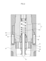
- FIG. 2 is an enlarged cross-sectional view of a portion of FIG. 1 in a closed state of the valve.
- FIG. 2 is an enlarged cross-sectional view of a portion of FIG. 1 in an open state.
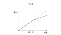
- 1 is a graph showing the relationship between load and deflection in a return spring with an uneven pitch.
- 4 is a graph showing the relationship between the number of turns and the spring constant of a return spring.
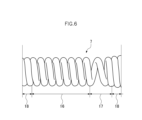
- FIG. 2 is a front view showing a specific example of a return spring used in the electromagnetic fuel injection valve of FIG. 1 .
- 4 is a graph showing a change in the lift amount of a valve body with respect to time when the electromagnetic fuel injection valve of FIG. 1 is in an open state.
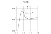
- FIG. 7B is an enlarged view of a portion of the graph in FIG. 7A.
- Fig. 1 shows an electromagnetic fuel injection valve according to one embodiment of the present invention.
- this electromagnetic fuel injection valve 1 comprises a valve housing 4 in which a fuel nozzle 2 (fuel injection hole) and a valve seat 3 are formed, a valve body 6 that enables fuel injection from the fuel nozzle 2 by lifting it from a closed position in contact with the valve seat 3 to an open position in response to excitation of a coil 5, and a return spring 7 that returns the valve body 6 to the closed position in contact with the valve seat 3.
- the lift of the valve body 6 to the open position is achieved by settling the overshoot and overshoot return that occur during the lift.
- the valve body 6 is composed of a rod 9 connected to a valve portion 8 that cooperates with the valve seat 3.
- the electromagnetic fuel injection valve 1 also includes a hollow fixed core 10 connected to the upstream end of the valve housing 4, a movable core 12 that faces an attraction surface 11 of the fixed core 10 and is slidably fitted onto the rod 9, and a valve-opening stopper 13 that is fixed to the rod 9 and comes into contact with the movable core 12 that is attracted to the attraction surface 11 when the coil 5 is energized, thereby opening the valve body 6.
- valve-closing stopper 14 is fixed to the rod 9 closer to the valve seat 3 than the valve-opening stopper 13.
- An auxiliary spring 15 is provided between the valve-opening stopper 13 and the movable core 12 to exert a spring force that moves the movable core 12 away from the valve-opening stopper 13 and into contact with the valve-closing stopper 14 when the coil 5 is not energized.
- the small pitch section 16 is in a fully compressed state when the lift amount of the valve body 6 is equal to or greater than a first lift amount that is smaller than the valve opening lift amount corresponding to the open valve position, and the large pitch section 17 is in operation when the lift amount is equal to or greater than a second lift amount that is equal to or less than half the valve opening lift amount.
- Figure 4 shows the relationship between load and deflection in such an unequal pitch return spring 7. As shown by the graph curve in Figure 4, when the load applied to the return spring 7 is equal to or less than the load L1 corresponding to the first lift amount at which the small pitch section 16 is fully compressed, only the small pitch section 16, which has a small spring constant, deflects, so the amount of deflection relative to the change in load is large.
- the load L2 corresponding to the second lift amount at which the large pitch section 17 functions is equal to or less than the load L1
- the large pitch section 17 which has a large spring constant, bends, so the amount of bending relative to the change in load becomes small. Therefore, the functions of the small pitch section 16 and the large pitch section 17 can be used in a continuous manner before and after the load L1.
- Figure 6 shows a more specific example of a return spring 7 configured by selecting the number of turns of the small pitch section 16 and the large pitch section 17 based on the relationship between the number of turns and spring constant in Figure 5.
- the small pitch section 16 of this return spring 7 is configured with 7.5 turns, with a spring constant of 20.57 N/mm and a pitch of 0.9985.
- the large pitch section 17 is configured with 1 turn, with a spring constant of 154.3 N/mm.
- the seat turns 18 on both sides of the return spring 7 are configured with 2 turns.
- the spring constant of the large pitch section 17 is more than seven times that of the small pitch section.
- the valve body 6 and the opening stopper 13 overshoot due to their inertia, but the overshooting stops when the closing stopper 14 integrated with the valve body 6 collides with the movable core 12.
- the opening stopper 13 moves away from the movable core 12 by an amount equal to the overshoot of the valve body 6, increasing the compressive deformation of the return spring 7, so that the repulsive force of the return spring 7 also suppresses the overshooting of the valve body 6.
- the repulsive force of the return spring 7 returns the valve opening stopper 13 to a position where it abuts against the movable core 12, which is in contact with the suction surface 11, and the valve body 6 is held in the specified open position.
- the biasing force of the auxiliary spring 15 is smaller than the biasing force of the return spring 7 which biases the valve body 6 in the valve closing direction, so the auxiliary spring 15 does not interfere with the attraction of the fixed core 10 to the movable core 12 and the abutment of the valve opening stopper 13 against the movable core 12 by the return spring 7 when the coil 5 is energized, and does not hinder the opening of the valve body 6 to the specified position.
- the impact force that the movable core 12 imparts to the suction surface 11 is divided into the impact force when only the movable core 12 first collides with the suction surface 11 and the impact force when the closing side stopper 14 subsequently collides with the movable core 12, so that the energy of each collision is relatively small, preventing wear at the contact points between the suction surface 11 and the movable core 12 and keeping collision noise low.
- the return spring 7 is deformed more than the amount of compressive deformation that occurs during normal valve opening, so that the return spring 7 absorbs the collision energy of the closing side stopper 14 with the movable core 12 and reduces the impact force.
- valve body 6 When the valve body 6 first sits on the valve seat 3, it bounces back due to the impact of the seating. However, the movable core 12, which descends with some delay, comes into contact with the closing stopper 14 fixed to the bouncing valve body 6, minimizing the amount of bouncing back of the valve body 6.
- valve body 6 When the rebound of the valve body 6 is suppressed, the valve body 6 is held in a closed state by the repulsive force of the return spring 7, stopping fuel injection, and the movable core 12 is held in contact with the closing side stopper 14 by the repulsive force of the auxiliary spring 15.
- the impact force that the valve disc 6 exerts on the valve seat 3 during the valve closing process is divided into the impact force when only the valve disc 6 first sits on the valve seat 3, and the impact force when the movable core 12 then collides with the closing stopper 14, so the collision energy of each is relatively small. Also, when the valve disc 6 first sits on the valve seat 3, it bounces off due to the seating impact, and then sits on the valve seat 3 again and exerts an impact, but the closing stroke of the valve disc 6 after bouncing off is much smaller than the closing stroke of the valve disc 6 from the normal open position, so the impact force on the valve seat 3 is very small. This prevents wear on the seating parts of the valve section 8 and the valve seat 3, and keeps seating noise low.
- Figure 7A shows the change in lift amount of the valve body 6 over time when the electromagnetic fuel injection valve 1 is in an open state as described above.
- Figure 7B shows an enlarged view of the rectangular box in Figure 7A.
- graph curve A shows the change in lift amount when the return spring 7 of this embodiment in Figure 6 is used.
- graph curve B shows the change in lift amount when a return spring with 7.5 turns, a spring constant of 20.57 N/mm, and a uniform pitch of 1.215 is used instead of the return spring 7.
- valve-opening stopper 13 When the valve is opened, the movable core 12 collides with the valve-opening stopper 13 in response to the passage of current through the coil 5. As shown in Figures 7A and 7B, the movable core 12 pushes up the valve-opening stopper 13 against the force of the return spring 7, increasing the lift of the valve body 6. When the movable core 12 reaches the valve-opening lift (valve-open position) at which it collides with the fixed core 10, the valve body 6 and the valve-opening stopper 13 leave the movable core 12 due to inertia, and move further upstream, taking the valve-closing stopper 14 with them, into an overshoot.
- the large pitch section 17 effectively suppresses overshoot and overshoot return when the valve is opened, stabilizing the operation of the valve body 6 and reducing variation in the flow rate.
- the spring constant of the large pitch section 17 is more than seven times that of the small pitch section 16, so that the appropriate pressing force of the large pitch section 17 can more effectively suppress overshoot and overshoot return, and further effectively reduce the variation in the flow rate.
- the large pitch section 17 is provided on the upstream side of the return spring, the fuel supplied to the inside of the return spring 7 can be circulated to the outside of the return spring 7 more quickly. This makes it possible to more effectively reduce the fluid pressure applied to the valve body 6 and more effectively improve the maximum operating fuel pressure of the electromagnetic fuel injection valve 1.
- the present invention is not limited to this.
- a hammering mechanism in which the movable core 12 is caused to collide with the valve-opening stopper 13 against the biasing force of the auxiliary spring 15 (hammering), and then the valve body 6 together with the valve-opening stopper 13 is pushed up to the valve-opening side against the biasing force of the return spring 7.
- hammering may be omitted and the valve body 6 may be directly pushed up to the valve-opening side by the movable core 12 against the biasing force of the return spring 7.
- SYMBOLS 1...electromagnetic fuel injection valve, 2...fuel nozzle, 3...valve seat, 4...valve housing, 5...coil, 6...valve body, 7...return spring, 8...valve portion, 9...rod, 10...fixed core, 11...suction surface, 12...movable core, 13...valve opening side stopper, 14...valve closing side stopper, 15...auxiliary spring, 16...small pitch portion, 17...large pitch portion, 18...seat turn, 19...fuel supply tube, 20...retainer, 21...hollow portion, 22...flat portion, 23...through hole, 24...flat portion, A, B...graph curves.
Landscapes
- Engineering & Computer Science (AREA)
- Chemical & Material Sciences (AREA)
- Combustion & Propulsion (AREA)
- Mechanical Engineering (AREA)
- General Engineering & Computer Science (AREA)
- Fuel-Injection Apparatus (AREA)
Priority Applications (2)
| Application Number | Priority Date | Filing Date | Title |
|---|---|---|---|
| PCT/JP2022/046064 WO2024127558A1 (ja) | 2022-12-14 | 2022-12-14 | 電磁式燃料噴射弁 |
| JP2024564043A JP7777243B2 (ja) | 2022-12-14 | 2022-12-14 | 電磁式燃料噴射弁 |
Applications Claiming Priority (1)
| Application Number | Priority Date | Filing Date | Title |
|---|---|---|---|
| PCT/JP2022/046064 WO2024127558A1 (ja) | 2022-12-14 | 2022-12-14 | 電磁式燃料噴射弁 |
Publications (1)
| Publication Number | Publication Date |
|---|---|
| WO2024127558A1 true WO2024127558A1 (ja) | 2024-06-20 |
Family
ID=91484594
Family Applications (1)
| Application Number | Title | Priority Date | Filing Date |
|---|---|---|---|
| PCT/JP2022/046064 Ceased WO2024127558A1 (ja) | 2022-12-14 | 2022-12-14 | 電磁式燃料噴射弁 |
Country Status (2)
| Country | Link |
|---|---|
| JP (1) | JP7777243B2 (https=) |
| WO (1) | WO2024127558A1 (https=) |
Citations (5)
| Publication number | Priority date | Publication date | Assignee | Title |
|---|---|---|---|---|
| JPS63118376U (https=) * | 1987-01-27 | 1988-07-30 | ||
| JPH1030518A (ja) * | 1996-07-12 | 1998-02-03 | Zexel Corp | 電磁式燃料噴射弁 |
| JP2004169730A (ja) * | 2002-11-18 | 2004-06-17 | Isuzu Motors Ltd | 圧縮コイルばね |
| JP2010190178A (ja) * | 2009-02-20 | 2010-09-02 | Denso Corp | 燃料噴射装置 |
| JP2013096255A (ja) * | 2011-10-28 | 2013-05-20 | Toyota Motor Corp | 圧力制御装置および燃料供給装置 |
Family Cites Families (1)
| Publication number | Priority date | Publication date | Assignee | Title |
|---|---|---|---|---|
| JP6232144B2 (ja) | 2014-09-18 | 2017-11-15 | 日立オートモティブシステムズ株式会社 | 燃料噴射弁 |
-
2022
- 2022-12-14 JP JP2024564043A patent/JP7777243B2/ja active Active
- 2022-12-14 WO PCT/JP2022/046064 patent/WO2024127558A1/ja not_active Ceased
Patent Citations (5)
| Publication number | Priority date | Publication date | Assignee | Title |
|---|---|---|---|---|
| JPS63118376U (https=) * | 1987-01-27 | 1988-07-30 | ||
| JPH1030518A (ja) * | 1996-07-12 | 1998-02-03 | Zexel Corp | 電磁式燃料噴射弁 |
| JP2004169730A (ja) * | 2002-11-18 | 2004-06-17 | Isuzu Motors Ltd | 圧縮コイルばね |
| JP2010190178A (ja) * | 2009-02-20 | 2010-09-02 | Denso Corp | 燃料噴射装置 |
| JP2013096255A (ja) * | 2011-10-28 | 2013-05-20 | Toyota Motor Corp | 圧力制御装置および燃料供給装置 |
Also Published As
| Publication number | Publication date |
|---|---|
| JPWO2024127558A1 (https=) | 2024-06-20 |
| JP7777243B2 (ja) | 2025-11-27 |
Similar Documents
| Publication | Publication Date | Title |
|---|---|---|
| CN101725445B (zh) | 电磁式燃料喷射阀 | |
| US8857743B2 (en) | Fuel injection valve | |
| KR100347430B1 (ko) | 충돌완화된아마츄어와니들밸브조립체 | |
| CN104508291B (zh) | 电磁式燃料喷射阀 | |
| US7163162B2 (en) | Fuel-injection valve | |
| US8128009B2 (en) | Fuel injection valve | |
| EP2336544A1 (en) | Anti-bounce mechanism for fuel injectors | |
| US7156368B2 (en) | Solenoid actuated flow controller valve | |
| CN106894927B (zh) | 电磁式燃料喷射阀 | |
| KR20140032453A (ko) | 유체 분사용 분사기 | |
| CN112539125B (zh) | 电磁式燃料喷射阀 | |
| JP2004519609A (ja) | 内燃機関の噴射弁を制御するための電磁弁 | |
| US6811138B2 (en) | Magnetic valve for controlling an injection valve of an internal combustion engine | |
| JP7777243B2 (ja) | 電磁式燃料噴射弁 | |
| GB2341893A (en) | Two-stage electromagnetically actuated fuel injector for i.c. engines | |
| US20260117732A1 (en) | Electromagnetic fuel injection valve | |
| EP1063419A2 (en) | Fuel injection valve | |
| CN114635819B (zh) | 一种实现多次喷射稳定的高压共轨喷油器高速电磁阀 | |
| JP4078165B2 (ja) | 燃料噴射弁 | |
| JP7728450B2 (ja) | 燃料噴射弁及びオリフィス部材 | |
| JP6640763B2 (ja) | 燃料噴射装置 | |
| WO2025069435A1 (ja) | 電磁弁駆動装置 | |
| JPH0567880U (ja) | 流体制御用ソレノイド弁 | |
| JP4464372B2 (ja) | 燃料噴射弁 | |
| JP2010190181A (ja) | 燃料噴射弁 |
Legal Events
| Date | Code | Title | Description |
|---|---|---|---|
| 121 | Ep: the epo has been informed by wipo that ep was designated in this application |
Ref document number: 22968469 Country of ref document: EP Kind code of ref document: A1 |
|
| WWE | Wipo information: entry into national phase |
Ref document number: 2024564043 Country of ref document: JP |
|
| WWE | Wipo information: entry into national phase |
Ref document number: 18872522 Country of ref document: US |
|
| NENP | Non-entry into the national phase |
Ref country code: DE |
|
| 122 | Ep: pct application non-entry in european phase |
Ref document number: 22968469 Country of ref document: EP Kind code of ref document: A1 |