WO2024127447A1 - 室外機、および冷凍サイクル装置 - Google Patents
室外機、および冷凍サイクル装置 Download PDFInfo
- Publication number
- WO2024127447A1 WO2024127447A1 PCT/JP2022/045594 JP2022045594W WO2024127447A1 WO 2024127447 A1 WO2024127447 A1 WO 2024127447A1 JP 2022045594 W JP2022045594 W JP 2022045594W WO 2024127447 A1 WO2024127447 A1 WO 2024127447A1
- Authority
- WO
- WIPO (PCT)
- Prior art keywords
- holes
- opening area
- rotation axis
- frame portion
- total opening
- Prior art date
- Legal status (The legal status is an assumption and is not a legal conclusion. Google has not performed a legal analysis and makes no representation as to the accuracy of the status listed.)
- Ceased
Links
Images




Classifications
-
- F—MECHANICAL ENGINEERING; LIGHTING; HEATING; WEAPONS; BLASTING
- F24—HEATING; RANGES; VENTILATING
- F24F—AIR-CONDITIONING; AIR-HUMIDIFICATION; VENTILATION; USE OF AIR CURRENTS FOR SCREENING
- F24F1/00—Room units for air-conditioning, e.g. separate or self-contained units or units receiving primary air from a central station
- F24F1/06—Separate outdoor units, e.g. outdoor unit to be linked to a separate room comprising a compressor and a heat exchanger
- F24F1/56—Casing or covers of separate outdoor units, e.g. fan guards
Definitions
- This disclosure relates to an outdoor unit and a refrigeration cycle device.
- Patent Document 1 describes an outdoor unit for an air conditioner as such an outdoor unit.
- the air sent from the blower fan is blown out of the housing from an outlet formed in the outdoor unit's housing while spreading radially outward from the axis of rotation of the blower fan.
- the air blown out from the lower vertical part of the outlet hits the installation surface on which the outdoor unit is installed, so frictional force is generated between the blown air and the installation surface.
- the air blown out from the upper vertical part of the outlet does not hit the installation surface. Therefore, the ventilation resistance experienced by the air blown out from the lower part of the outlet is greater than the ventilation resistance experienced by the air blown out from the upper part of the outlet.
- the flow rate of the air blown out from the upper part of the outlet is likely to be greater than the flow rate of the air blown out from the lower part of the outlet, and the flow velocity of the air blown out from the upper part of the outlet is likely to be greater than the flow velocity of the air blown out from the lower part of the outlet. Therefore, there was a problem that the noise generated when the air blown out from the upper part of the outlet passes through the through hole formed in the fan grill is likely to be large.
- one of the objectives of this disclosure is to provide an outdoor unit having a structure that can prevent noise from increasing, and a refrigeration cycle device equipped with such an outdoor unit.
- One aspect of the outdoor unit according to the present disclosure is an outdoor unit for a refrigeration cycle device, comprising a housing having an air outlet, a blower fan having rotors arranged inside the housing facing the air outlet, and a fan grill having a plurality of through holes and covering the air outlet from the outside of the housing, wherein the total opening area of the through holes formed in a lower portion of the fan grill located vertically below the axis of rotation of the rotors is greater than the total opening area of the through holes formed in an upper portion of the fan grill located vertically above the axis of rotation.
- One embodiment of the refrigeration cycle device disclosed herein includes the outdoor unit and indoor unit described above.
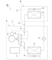
- FIG. 1 is a schematic diagram showing a general configuration of a refrigeration cycle device in a first embodiment.
- FIG. FIG. 2 is a perspective view showing the outdoor unit according to the first embodiment.
- FIG. 2 is a front view of the outdoor unit according to the first embodiment.
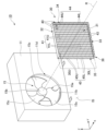
- FIG. 2 is an exploded perspective view showing the outdoor unit according to the first embodiment.
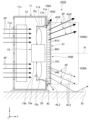
- FIG. 4 is a cross-sectional view showing the outdoor unit in the first embodiment, taken along line VV in FIG.
- FIG. 11 is a perspective view showing a fan grill in a second embodiment.
- FIG. 11 is a perspective view showing a fan grill in a third embodiment.
- FIG. 13 is a perspective view showing a fan grill in a fourth embodiment.
- FIG. 13 is a perspective view showing a fan grill in a fifth embodiment.
- FIG. 23 is a perspective view showing a fan grill in a sixth embodiment.
- FIG. 23 is a front view of the outdoor unit in the seventh embodiment.
- FIG. 23 is a front view of the outdoor unit in embodiment 8.
- FIG. 13 is a perspective view showing a fan grill in a ninth embodiment.
- FIG. 4 is a cross-sectional view showing an outdoor unit of a comparative example.
- the drawings also show the X-axis, Y-axis, and Z-axis as appropriate.
- the X-axis shows one of the horizontal directions.
- the Y-axis shows the other of the horizontal directions.
- the Z-axis shows the vertical direction.
- the horizontal direction along the X-axis is called the "front-rear direction X”
- the horizontal direction along the Y-axis is called the "left-right direction Y”
- the vertical direction along the Z-axis is called the "vertical direction Z”.
- the front-rear direction X, the left-right direction Y, and the vertical direction Z are mutually perpendicular directions.
- the side of the vertical direction Z toward which the Z-axis arrow points (+Z side) is the upper side
- the opposite side of the vertical direction Z to the side toward which the Z-axis arrow points (-Z side) is the lower side
- the side of the front-rear direction X toward which the X-axis arrow points (+X side) is the front side
- the opposite side of the front-rear direction X to the side toward which the X-axis arrow points (-X side) is the rear side.
- the left-right direction Y is the left-right direction when the outdoor unit in each of the following embodiments is viewed from the front (+X side).
- the side toward which the Y-axis arrow points in the left-right direction Y (+Y side) is the right side
- the side opposite to the side toward which the Y-axis arrow points in the left-right direction Y (-Y side) is the left side
- FIG. 1 is a schematic diagram showing a schematic configuration of a refrigeration cycle apparatus 100 in the first embodiment.
- the refrigeration cycle apparatus 100 is an apparatus that utilizes a refrigeration cycle in which a refrigerant 19 circulates.
- the refrigeration cycle apparatus 100 is an air conditioner.
- the refrigeration cycle apparatus 100 includes an outdoor unit 10, an indoor unit 20, and a circulation path section 18.
- the outdoor unit 10 is disposed outdoors.
- the indoor unit 20 is disposed indoors.
- the outdoor unit 10 and the indoor unit 20 are connected to each other by the circulation path section 18 in which the refrigerant 19 circulates.
- the outdoor unit 10 and the indoor unit 20 are heat exchange units that exchange heat with air.
- the refrigeration cycle device 100 can adjust the temperature of the air in the room by exchanging heat between the refrigerant 19 flowing in the circulation path section 18 and the air in the room in which the indoor unit 20 is located.
- the refrigerant 19 include fluorine-based refrigerants or hydrocarbon-based refrigerants that have a low global warming potential (GWP).
- the outdoor unit 10 comprises a housing 11, a compressor 12, a heat exchanger 13, a flow control valve 14, a blower fan 15, a four-way valve 16, and a control unit 17.
- the housing 11 contains the compressor 12, the heat exchanger 13, the flow control valve 14, the blower fan 15, the four-way valve 16, and the control unit 17.
- the compressor 12, heat exchanger 13, flow rate control valve 14, and four-way valve 16 are provided in a portion of the circulation path 18 that is located inside the housing 11.
- the compressor 12, heat exchanger 13, flow rate control valve 14, and four-way valve 16 are connected by a portion of the circulation path 18 that is located inside the housing 11.
- the four-way valve 16 is provided in a portion of the circulation path section 18 that is connected to the discharge side of the compressor 12.
- the four-way valve 16 can reverse the direction of the refrigerant 19 flowing through the circulation path section 18 by switching a portion of the path of the circulation path section 18.
- the path connected by the four-way valve 16 is the path shown by the solid line on the four-way valve 16 in FIG. 1
- the refrigerant 19 flows through the circulation path section 18 in the direction shown by the solid arrow in FIG. 1.
- the path connected by the four-way valve 16 is the path shown by the dashed line on the four-way valve 16 in FIG. 1, the refrigerant 19 flows through the circulation path section 18 in the direction shown by the dashed arrow in FIG. 1.
- the indoor unit 20 comprises a housing 21, a heat exchanger 22, and a blower fan 23.
- the housing 21 houses the heat exchanger 22 and the blower fan 23 inside.
- the indoor unit 20 is capable of cooling operation to cool the air in the room in which the indoor unit 20 is located, and heating operation to warm the air in the room in which the indoor unit 20 is located.
- the refrigerant 19 flowing in the circulation path 18 flows in the direction shown by the solid arrow in Figure 1.
- the refrigerant 19 flowing in the circulation path 18 circulates through the compressor 12, the heat exchanger 13 of the outdoor unit 10, the flow control valve 14, and the heat exchanger 22 of the indoor unit 20, in that order, before returning to the compressor 12.
- the heat exchanger 13 in the outdoor unit 10 functions as a condenser
- the heat exchanger 22 in the indoor unit 20 functions as an evaporator.
- the refrigerant 19 flowing in the circulation path portion 18 flows in the direction shown by the dashed line in Figure 1.
- the refrigerant 19 flowing in the circulation path portion 18 circulates through the compressor 12, the heat exchanger 22 of the indoor unit 20, the flow control valve 14, and the heat exchanger 13 of the outdoor unit 10, in that order, before returning to the compressor 12.
- the heat exchanger 13 in the outdoor unit 10 functions as an evaporator
- the heat exchanger 22 in the indoor unit 20 functions as a condenser.
- Figure 2 is a perspective view of the outdoor unit 10.
- Figure 3 is a view of the outdoor unit 10 as seen from the front side (+X side).
- Figure 4 is an exploded perspective view of the outdoor unit 10.
- Figure 5 is a cross-sectional view of the outdoor unit 10, taken along the line V-V in Figure 3.
- the housing 11 of the outdoor unit 10 is a generally rectangular box shape that is long in the left-right direction Y.
- the housing 11 is installed on an installation surface IS.
- the installation surface IS is not particularly limited, and may be, for example, the ground, the floor of a building rooftop, the floor of a veranda, or the floor of a balcony.
- the housing 11 has an air outlet 11b from which air AF is blown out.
- the air outlet 11b is formed in a wall portion located on the front side (+X side) of the housing 11.
- the outdoor unit 10 in embodiment 1 is a side-blowing type outdoor unit in which the air AF outlet 11b is formed in the front wall portion of the housing 11.
- the air outlet 11b penetrates the wall portion located on the front side of the housing 11 in the front-rear direction X and opens forward.
- the air outlet 11b is circular with the rotation axis R, which will be described later, as its center.
- the front surface of the housing 11 in which the air outlet 11b is formed is, for example, perpendicular to the installation surface IS.
- the housing 11 has a housing main body 11c in the shape of a substantially rectangular box, and a bellmouth 11d attached to the housing main body 11c.
- the bellmouth 11d is a member that guides the air AF blown forward (+X direction) from the blower fan 15.
- the bellmouth 11d is also called a shroud.
- the bellmouth 11d is cylindrical and surrounds the rotor 15a of the blower fan 15, which will be described later, and opens on both sides in the front-rear direction X. More specifically, the bellmouth 11d is substantially cylindrical and centered on the rotation axis R, which will be described later.
- the inner and outer diameters of the front part of the bellmouth 11d increase toward the front.
- the front end of the bellmouth 11d is located in a hole 11e formed in the front wall of the housing main body 11c. In the first embodiment, the front end of the bellmouth 11d is an air outlet 11b formed in the housing 11.
- the blower fan 15 is a propeller fan.
- the blower fan 15 is located in front of the heat exchanger 13 (+X direction).
- the blower fan 15 has rotors 15a that can rotate around a rotation axis R that extends in the front-rear direction X.
- the rotors 15a are rotated around the rotation axis R by a motor (not shown).
- the rotation axis R is a virtual axis that extends in the front-rear direction X. That is, in the first embodiment, the axial direction of the rotation axis R is the front-rear direction X.
- the radial direction centered on the rotation axis R may be simply referred to as the "radial direction”
- the circumferential direction around the rotation axis R may be simply referred to as the "circumferential direction”.
- the rotor 15a is disposed facing the air outlet 11b inside the housing 11. When viewed from the front (+X direction), the entire rotor 15a is located inside the inner edge of the air outlet 11b. The rotor 15a is located behind the air outlet 11b (-X direction).
- the rotor 15a has a base 15b fixed to the shaft of a motor (not shown) and multiple blades 15c protruding radially outward from the base 15b.
- the multiple blades 15c are arranged at intervals in the circumferential direction. In the first embodiment, three blades 15c are provided.
- the air AF sucked into the housing 11 by the rotor 15a passes through the heat exchanger 13 and the rotor 15a, and is blown out to the front of the housing 11 from the air outlet 11b.
- the suction ports 11a are arranged in a grid pattern, for example.
- the outdoor unit 10 is equipped with a fan grill 30 that covers the air outlet 11b from outside the housing 11.
- the fan grill 30 is a member provided to prevent human hands from touching the rotor 15a.
- the fan grill 30 is attached to the housing 11.
- the fan grill 30 is fixed to the housing 11, for example, by screws.
- the fan grill 30 may also be attached to the housing 11, for example, by locking claws.
- the fan grill 30 is rectangular when viewed in the front-rear direction X, having a pair of sides extending in the left-right direction Y and a pair of sides extending in the vertical direction Z. More specifically, the fan grill 30 is substantially square when viewed in the front-rear direction X. In the first embodiment, the fan grill 30 is thin in the front-rear direction X and substantially box-shaped, opening on the rear side (-X side). The fan grill 30 covers the entire air outlet 11b from the front (+X side). In the first embodiment, the center CL1 of the fan grill 30 in the vertical direction Z is located at the same position as the rotation axis R in the vertical direction Z.
- the fan grill 30 has a facing portion 31 and an outer frame portion 36.
- the facing portion 31 is disposed facing the air outlet 11b in the axial direction of the rotation axis R, i.e., in the front-rear direction X.
- the facing portion 31 is located in front of the air outlet 11b (+X direction).
- the rotation axis R passes through the facing portion 31.
- the facing portion 31 is rectangular when viewed in the front-rear direction X, having a pair of sides extending in the left-right direction Y and a pair of sides extending in the vertical direction Z.
- the outer peripheral edge portion of the facing portion 31 is located radially outward from the air outlet 11b.
- the dimension of the facing portion 31 in the left-right direction Y is larger than the dimension of the air outlet 11b in the left-right direction Y, i.e., the inner diameter of the air outlet 11b.
- the dimension of the facing portion 31 in the vertical direction Z is larger than the dimension of the air outlet 11b in the vertical direction Z, i.e., the inner diameter of the air outlet 11b.
- the outer frame portion 36 protrudes from the outer peripheral edge of the facing portion 31 toward the housing 11.
- the outer frame portion 36 is a rectangular frame that protrudes rearward (in the -X direction) from the outer peripheral edge of the facing portion 31.
- the rear end of the outer frame portion 36 is fixed to the front wall of the housing 11.
- the outer frame portion 36 has a fixing portion that is fixed to the housing 11 by screws.
- the outer frame portion 36 has an upper frame portion 32, a lower frame portion 33, and a pair of side frame portions 34, 35.
- the upper frame portion 32 is a portion of the outer frame portion 36 located above in the vertical direction Z.
- the upper frame portion 32 is located above the rotation axis R in the vertical direction Z.
- the lower frame portion 33 is a portion of the outer frame portion 36 located below in the vertical direction Z.
- the lower frame portion 33 is located below the rotation axis R in the vertical direction Z.
- the upper frame portion 32 and the lower frame portion 33 extend in the axial direction of the rotation axis R, i.e., in a direction intersecting the vertical direction Z when viewed in the front-rear direction X. More specifically, the upper frame portion 32 and the lower frame portion 33 extend in the left-right direction Y.
- the upper frame portion 32 and the lower frame portion 33 are disposed opposite each other with a gap in between in the vertical direction Z.
- the upper frame portion 32 is plate-shaped with a plate surface facing the vertical direction Z.
- the pair of side frame portions 34, 35 are portions located in the left-right direction Y perpendicular to both the vertical direction Z and the axial direction of the rotation axis R, i.e., the front-rear direction X.
- the pair of side frame portions 34, 35 extend in the vertical direction Z.
- the pair of side frame portions 34, 35 are arranged opposite each other with a gap in between in the left-right direction Y.
- the side frame portion 34 is a portion located on the right side (+Y side) of the outer frame portion 36.
- the side frame portion 35 is a portion located on the left side (-Y side) of the outer frame portion 36.
- the side frame portion 34 connects the right end of the upper frame portion 32 to the right end of the lower frame portion 33.
- the side frame portion 35 connects the left end of the upper frame portion 32 to the left end of the lower frame portion 33.
- the fan grill 30 has a plurality of through holes 40.
- Each through hole 40 penetrates the portion of the fan grill 30 in which the through hole 40 is formed.
- At least one through hole 40 is formed in each of the facing portion 31 and the outer frame portion 36.
- the plurality of through holes 40 includes a through hole 41 formed in the facing portion 31, a through hole 43 formed in the lower frame portion 33 of the outer frame portion 36, a through hole 44 formed in the side frame portion 34 of the outer frame portion 36, and a through hole 45 formed in the side frame portion 35 of the outer frame portion 36.
- Each of the through holes 41, 43, 44, and 45 is formed in a plurality of numbers.
- the upper frame portion 32 does not have a through hole 40.
- through holes 40 when the through holes are not particularly distinguished, they are collectively referred to as "through holes 40".
- the multiple through holes 41 formed in the opposing portion 31 penetrate the opposing portion 31 in the front-rear direction X.
- the multiple through holes 41 are arranged in a matrix. More specifically, multiple rows of the multiple through holes 41 aligned in the left-right direction Y are aligned in multiple rows in the vertical direction Z.
- each through hole 41 is a rectangular hole that is long in the left-right direction Y.
- the shapes of the through holes 41 are the same as each other.
- the opening areas of the through holes 41 are the same as each other.
- the multiple through holes 41 include a lower through hole 41L located below the rotation axis R in the vertical direction Z, and an upper through hole 41U located above the rotation axis R in the vertical direction Z.
- a plurality of lower through holes 41L and upper through holes 41U are formed.
- the number of lower through holes 41L and the number of upper through holes 41U are the same.
- the total opening area of the lower through holes 41L and the total opening area of the upper through holes 41U are the same.
- the total opening area of a certain through hole refers to the opening area of the one through hole when there is one through hole, and refers to the total area obtained by adding up the opening areas of the plurality of through holes when there are a plurality of through holes. That is, for example, the total opening area of the lower through hole 41L is the total area obtained by adding up the opening areas of the plurality of lower through holes 41L. Also, the "opening area of a certain through hole” refers to the area of a certain through hole when viewed in the penetrating direction of the certain through hole.
- the opening area of the through hole 41 formed in the opposing portion 31 is the area of the through hole 41 when viewed in the front-rear direction X in which the through hole 41 penetrates the opposing portion 31.
- the "penetrating direction of a certain through hole” refers to, for example, a direction perpendicular to a virtual plane along the opening edge of a certain through hole.
- the multiple through holes 43 formed in the lower frame portion 33 penetrate the lower frame portion 33 in the vertical direction Z.
- the multiple through holes 43 are arranged side by side in the left-right direction Y.
- each through hole 43 is a rectangular hole that is long in the front-rear direction X.
- the shapes of each through hole 43 are the same.
- the opening areas of each through hole 43 are the same.
- the number of through holes 43 is less than the number of through holes 41 formed in the opposing portion 31.
- the multiple through holes 44 formed in the side frame portion 34 penetrate the side frame portion 34 in the left-right direction Y.
- the multiple through holes 44 are arranged side by side in the vertical direction Z.
- each through hole 44 is a rectangular hole that is long in the front-rear direction X.
- the shapes of each through hole 44 are the same.
- the opening areas of each through hole 44 are the same.
- the number of through holes 44 is less than the number of through holes 41 formed in the opposing portion 31.
- the multiple through holes 44 include a lower through hole 44L located below the rotation axis R in the vertical direction Z, and an upper through hole 44U located above the rotation axis R in the vertical direction Z.
- a plurality of lower through holes 44L and upper through holes 44U are formed.
- the number of lower through holes 44L and the number of upper through holes 44U are the same.
- the total opening area of the lower through holes 44L and the total opening area of the upper through holes 44U are the same.
- the multiple through holes 45 formed in the side frame portion 35 penetrate the side frame portion 35 in the left-right direction Y.
- the multiple through holes 45 are arranged side by side in the vertical direction Z.
- each through hole 45 is a rectangular hole that is long in the front-rear direction X.
- the shapes of each through hole 45 are the same.
- the opening areas of each through hole 45 are the same.
- the number of through holes 45 is less than the number of through holes 41 formed in the opposing portion 31.
- the multiple through holes 45 include a lower through hole 45L located below the rotation axis R in the vertical direction Z, and an upper through hole 45U located above the rotation axis R in the vertical direction Z.
- a plurality of lower through holes 45L and a plurality of upper through holes 45U are formed.
- the number of lower through holes 45L and the number of upper through holes 45U are the same.
- the total opening area of the lower through holes 45L and the total opening area of the upper through holes 45U are the same.
- the shape and opening area of the through holes 45 formed in the side frame portion 35 are the same as the shape and opening area of the through holes 44 formed in the side frame portion 34.
- the number of through holes 45 is the same as the number of through holes 44.
- the number of lower through holes 45L is the same as the number of lower through holes 44L.
- the number of upper through holes 45U is the same as the number of upper through holes 44U.
- the total opening area of the lower through holes 45L is the same as the total opening area of the lower through holes 44L.
- the total opening area of the upper through holes 45U is the same as the total opening area of the upper through holes 44U.
- each through hole 41 formed in the opposing portion 31, the opening area of each through hole 43 formed in the lower frame portion 33, the opening area of each through hole 44 formed in the side frame portion 34, and the opening area of each through hole 45 formed in the side frame portion 35 may be the same as or different from each other.
- the total opening area of the through holes 40 formed in the lower portion 30L of the fan grill 30 located below the rotation axis R in the vertical direction Z is greater than the total opening area of the through holes 40 formed in the upper portion 30U of the fan grill 30 located above the rotation axis R in the vertical direction Z.
- the lower portion 30L is the portion of the fan grill 30 located below the rotation axis R in the vertical direction Z.
- the lower portion 30L has a portion of the opposing portion 31 located below the rotation axis R, a portion of the pair of side frame portions 34, 35 located below the rotation axis R, and a lower frame portion 33.
- the through holes 40 formed in the lower portion 30L include lower through holes 41L, 44L, 45L and a through hole 43 formed in the lower frame portion 33.
- the total opening area of the through holes 40 formed in the lower portion 30L is the sum of the total opening area of the lower through holes 41L, the total opening area of the lower through holes 44L, the total opening area of the lower through holes 45L, and the total opening area of the through holes 43.
- the upper portion 30U is a portion of the fan grill 30 located above the rotation axis R in the vertical direction Z.
- the upper portion 30U has a portion of the opposing portion 31 located above the rotation axis R, a portion of the pair of side frame portions 34, 35 located above the rotation axis R, and an upper frame portion 32.
- the through holes 40 formed in the upper portion 30U include upper through holes 41U, 44U, and 45U.
- the total opening area of the through holes 40 formed in the upper portion 30U is the sum of the total opening area of the upper through holes 41U, the total opening area of the upper through holes 44U, and the total opening area of the upper through holes 45U.
- no through holes 40 are formed in the upper frame 32 of the upper part 30U.
- through holes 40 are formed in the lower frame 33 of the lower part 30L.
- the total opening area of the through holes 40 formed in the upper part 30U is smaller than the total opening area of the through holes 40 formed in the lower part 30L by the amount that the through holes 40 are not formed in the upper frame 32.
- the difference between the total opening area of the through holes 40 formed in the lower part 30L and the total opening area of the through holes 40 formed in the upper part 30U is equal to the total opening area of the through holes 43 formed in the lower frame 33.
- the total opening area of the through holes 40 formed in the portion of the outer frame 36 located below the rotation axis R in the vertical direction Z is larger than the total opening area of the through holes 40 formed in the portion of the outer frame 36 located above the rotation axis R in the vertical direction Z.
- the total opening area of the through holes 40 formed in the portion of the outer frame 36 located below the rotation axis R in the vertical direction Z is the sum of the total opening area of the through holes 43 formed in the lower frame 33, the total opening area of the lower through holes 44L formed in the side frame 34, and the total opening area of the lower through holes 45L formed in the side frame 35.
- the total opening area of the through holes 40 formed in the portion of the outer frame 36 located above the rotation axis R in the vertical direction Z is the sum of the total opening area of the upper through holes 44U formed in the side frame 34 and the total opening area of the upper through holes 45U formed in the side frame 35.
- the fan grill 30 may be made of resin or metal. If the fan grill 30 is made of resin, it is made by a molding method using a mold, such as injection molding. If the fan grill 30 in the first embodiment is made of metal, for example, the parts of the fan grill 30 except for the upper frame part 32 are made of metal wire. In this case, for example, the metal wire is arranged in a lattice pattern, and through holes 40 are formed between adjacent wire parts with a gap between them.
- the cross-sectional shape of the metal wire forming the fan grill 30 is not particularly limited, and may be circular or elliptical.
- the portion shown as the line dividing the through holes 40 in each figure is formed of metal wire.
- the inside of a rectangular frame made of wire may be divided into a lattice shape by a plurality of bars made of wire extending in the vertical direction Z and bars made of wire extending in the left-right direction Y, forming the opposing portion 31 in which a plurality of through holes 41 are formed.
- the fan grill 30 of embodiment 1 is made of metal, for example, the upper frame portion 32 of the fan grill 30 is made of sheet metal.
- FIG. 14 is a cross-sectional view showing an outdoor unit 1010 of a comparative example.
- the outdoor unit 1010 of the comparative example has a fan grill 1030 with a different configuration from the fan grill 30 of the first embodiment.
- through holes 1042 are formed in the upper frame portion 1032 of the fan grill 1030.
- the total opening area of the through holes 1042 formed in the upper frame portion 1032 is the same as the total opening area of the through holes 43 formed in the lower frame portion 33.
- the total opening area of the lower portion 1030L of the fan grill 1030 located below the rotation axis R in the vertical direction Z is the same as the total opening area of the upper portion 1030U of the fan grill 1030 located above the rotation axis R in the vertical direction Z.
- the air AF that is sucked into the housing 11 by the blower fan 15 and then blown out from the outlet 11b includes lower air AL2 blown out from the lower part of the outlet 11b and upper air AU2 blown out from the upper part of the outlet 11b.
- the air AF blown out from the blower fan 15 flows forward (in the +X direction) while spreading outward in the radial direction due to the centrifugal force it receives when it is blown out from the blower fan 15.
- the lower air AL2 After being blown out from the air outlet 11b, the lower air AL2 passes through the through-holes 40 formed in the lower part 1030L of the fan grill 1030.
- the lower air AL2 is blown out obliquely in a direction that positions it downward as it moves toward the front side (+X side). At least a portion of the lower air AL2 hits the installation surface IS on which the outdoor unit 1010 is installed, and is subjected to a frictional force generated between the installation surface IS.
- the upper air AU2 After being blown out from the air outlet 11b, the upper air AU2 passes through the through-hole 40 formed in the upper part 1030U of the fan grill 1030.
- the upper air AU2 is blown out obliquely in a direction that is located upward as it moves toward the front side (+X side).
- the upper air AU2 does not hit the installation surface IS. Therefore, the ventilation resistance experienced by the upper air AU2 is smaller than the ventilation resistance experienced by the lower air AL2.
- the air AF blown out from the blower fan 15 is biased upward, and the flow rate of the upper air AU2 is likely to be greater than the flow rate of the lower air AL2.
- the flow velocity of the upper air AU2 is likely to be greater than the flow velocity of the lower air AL2. Therefore, the flow velocity of the upper air AU2 is likely to be excessively large, and the noise generated when the upper air AU2 passes through the through-hole 40 of the fan grill 1030 is likely to be large. In addition, the loss of the upper air AU2 that occurs when passing through the through hole 40 tends to increase, and the blowing efficiency of the blower fan 15 tends to decrease.
- the total opening area of the through holes 40 formed in the lower portion 30L of the fan grill 30 located below the rotation axis R of the rotor 15a in the vertical direction Z is larger than the total opening area of the through holes 40 formed in the upper portion 30U of the fan grill 30 located above the rotation axis R in the vertical direction Z. Therefore, the ventilation resistance experienced by the air AF when passing through the lower portion 30L of the fan grill 30 located below the rotation axis R can be made smaller than the ventilation resistance experienced by the air AF when passing through the upper portion 30U of the fan grill 30 located above the rotation axis R.
- the noise generated when the air AF passes through the through holes 40 formed in the fan grill 30 can be prevented from increasing.
- the loss of the air AF generated when passing through the through holes 40 formed in the fan grill 30 can be prevented from increasing. This prevents the power consumption of the blower fan 15 from increasing, and prevents the blowing efficiency of the blower fan 15 from decreasing.
- the lower air AL1 includes air AF passing through the lower through hole 41L formed in the opposing portion 31, air AF passing through the through hole 43 formed in the lower frame portion 33, and air AF passing through the lower through holes 44L, 45L formed in the pair of side frame portions 34, 35.
- the upper air AU1 includes air AF passing through the upper through hole 41U formed in the opposing portion 31, and air AF passing through the upper through holes 44U, 45U formed in the pair of side frame portions 34, 35.
- the total opening area of the through holes 40 formed in the lower part 30L is made larger than the total opening area of the through holes 40 formed in the upper part 30U so that the sum of the ventilation resistance that the lower air AL1 receives from the fan grill 30 and the ventilation resistance that the lower air AL1 receives from the installation surface IS is equivalent to the ventilation resistance that the upper air AU1 receives from the fan grill 30.
- This makes it possible to make the flow rate of the upper air AU1 and the flow rate of the lower air AL1 equivalent, and to make the flow speed of the upper air AU1 and the flow speed of the lower air AL1 equivalent. Therefore, it is possible to more appropriately prevent the noise generated when the air AF passes through the through holes 40 formed in the fan grill 30 from increasing. In addition, it is possible to more appropriately prevent the power consumption of the blower fan 15 from increasing, and it is possible to more appropriately prevent the blower fan 15 from decreasing in blowing efficiency.
- the fan grill 30 has a facing portion 31 arranged facing the air outlet 11b in the axial direction of the rotation axis R, and an outer frame portion 36 protruding from the outer peripheral edge of the facing portion 31 toward the housing 11. At least one through hole 40 is formed in each of the facing portion 31 and the outer frame portion 36. Therefore, the air AF can pass through the through holes 40 formed in each of the facing portion 31 and the outer frame portion 36. This makes it easier for the air AF to pass through the fan grill 30, and makes it easier to reduce the overall ventilation resistance experienced by the air AF blown out from the air outlet 11b. Therefore, it is possible to further suppress a decrease in the blowing efficiency of the blower fan 15.
- the total opening area of the through holes 40 formed in the portion of the outer frame 36 located below the rotation axis R in the vertical direction Z is larger than the total opening area of the through holes 40 formed in the portion of the outer frame 36 located above the rotation axis R in the vertical direction Z. Therefore, without changing the total opening area of the through holes 40 above and below the facing portion 31, the total opening area of the through holes 40 formed in the lower portion 30L can be made larger than the total opening area of the through holes 40 formed in the upper portion 30U. This allows the shape and size of the through holes 40 formed in the facing portion 31 to be the same regardless of the position in the vertical direction Z. Therefore, it is possible to prevent the design of the facing portion 31 from being deteriorated, and to prevent the design of the fan grill 30 from being deteriorated when viewed from the front (+X direction).
- At least one through hole 40 is formed in the lower frame portion 33 located on the lower side of the outer frame portion 36 in the vertical direction Z.
- No through hole 40 is formed in the upper frame portion 32 located on the upper side of the outer frame portion 36 in the vertical direction Z. Therefore, the total opening area of the through holes 40 formed in the lower portion 30L can be easily made larger than the total opening area of the through holes 40 formed in the upper portion 30U by the amount of the through holes 43 formed in the lower frame portion 33.
- the lower frame portion 33 is particularly difficult to see from the outside among the outer frame portions 36, even if the upper frame portion 32 and the lower frame portion 33 have different appearances, it is difficult to affect the design of the fan grill 30. Therefore, it is possible to further suppress a deterioration in the design of the fan grill 30.
- Embodiment 2. 6 is a perspective view showing a fan grill 230 in embodiment 2.
- the same components as those in the above-described embodiment are denoted by the same reference numerals as appropriate, and description thereof may be omitted.
- the upper frame portion 232 of the outer frame portion 236 has through holes 242 formed therein.
- the through holes 242 penetrate the upper frame portion 232 in the vertical direction Z.
- the through holes 242 are rectangular holes that are long in the front-rear direction X.
- a plurality of the through holes 242 are formed at intervals in the left-right direction Y.
- the shapes of the through holes 242 are the same as each other.
- the opening areas of the through holes 242 are the same as each other.
- the opening area of the through holes 242 is smaller than the opening area of the through holes 43 formed in the lower frame portion 33.
- the number of the through holes 242 is smaller than the number of the through holes 43 formed in the lower frame portion 33.
- the total opening area of the through holes 242 is smaller than the total opening area of the through holes 43.
- the total opening area of the through holes 43 formed in the lower frame portion 33 is larger than the total opening area of the through holes 242 formed in the upper frame portion 232.
- the rest of the configuration of the upper frame portion 232 is similar to the rest of the configuration of the upper frame portion 32 in embodiment 1.
- the rest of the configuration of the outer frame portion 236 is similar to the rest of the configuration of the outer frame portion 36 in embodiment 1.
- the rest of the configuration of the fan grill 230 is similar to the rest of the configuration of the fan grill 30 in embodiment 1.
- At least one through hole 40 is formed in each of the lower frame portion 33 located on the lower side of the outer frame portion 236 in the vertical direction Z and the upper frame portion 232 located on the upper side of the outer frame portion 236 in the vertical direction Z.
- the total opening area of the through holes 43 formed in the lower frame portion 33 is larger than the total opening area of the through holes 242 formed in the upper frame portion 232. This makes it possible to make the total opening area of the through holes 40 formed in the lower portion 230L of the fan grill 230 located below the rotation axis R in the vertical direction Z larger than the total opening area of the through holes 40 formed in the upper portion 230U of the fan grill 230 located above the rotation axis R in the vertical direction Z.
- through holes 242 are formed in the upper frame portion 232, which prevents rainwater and the like from accumulating on the upper frame portion 232.
- Embodiment 3. 7 is a perspective view showing a fan grill 330 in embodiment 3.
- the same components as those in the above-described embodiments are denoted by the same reference numerals as appropriate, and description thereof may be omitted.
- the upper frame portion 332 of the outer frame portion 336 has through holes 342 formed therein.
- the through holes 342 penetrate the upper frame portion 332 in the vertical direction Z.
- the through holes 342 are rectangular holes that are long in the front-rear direction X.
- a plurality of the through holes 342 are formed in the left-right direction Y.
- the shapes of the through holes 342 are the same as each other.
- the opening areas of the through holes 342 are the same as each other.
- the opening area of the through holes 342 is the same as the opening area of the through holes 43 formed in the lower frame portion 33.
- the number of the through holes 342 is the same as the number of the through holes 43 formed in the lower frame portion 33.
- the total opening area of the through holes 342 is the same as the total opening area of the through holes 43.
- the entire fan grill 330, including the upper frame portion 332 is made of metal wire.
- the lines between adjacent through holes 342 in the upper frame portion 332 shown in FIG. 7 are formed of wire.
- the through holes 341 formed in the facing portion 331 include a plurality of lower through holes 341L and a plurality of upper through holes 341U.
- the lower through holes 341L are through holes 341 formed in a portion of the facing portion 331 that is located below the rotation axis R.
- the upper through holes 341U are through holes 341 formed in a portion of the facing portion 331 that is located above the rotation axis R.
- the lower through holes 341L and the upper through holes 341U are rectangular holes that are long in the left-right direction Y.
- the lower through holes 341L are arranged in a matrix in the portion of the opposing portion 331 located below the rotation axis R. More specifically, the lower through holes 341L are arranged in a matrix in a row in the left-right direction Y.
- the upper through holes 341U are arranged in a matrix in the portion of the opposing portion 331 located above the rotation axis R. More specifically, the upper through holes 341U are arranged in a row in the left-right direction Y.
- the number of rows in which the lower through holes 341L are arranged in the vertical direction Z is less than the number of rows in which the upper through holes 341U are arranged in the vertical direction Z.
- Each row of the lower through holes 341L is arranged below two rows of upper through holes 341U adjacent to each other in the left-right direction Y.
- the number of the lower through holes 341L is less than the number of the upper through holes 341U.
- the number of the lower through holes 341L is half the number of the upper through holes 341U.
- the dimension of the lower through hole 341L in the left-right direction Y is larger than the dimension of the upper through hole 341U in the left-right direction Y.
- the dimension of the lower through hole 341L in the left-right direction Y is approximately twice the dimension of the upper through hole 341U in the left-right direction Y.
- the dimension of the lower through hole 341L in the vertical direction Z is the same as the dimension of the upper through hole 341U in the vertical direction Z.
- the opening area of the lower through hole 341L is larger than the opening area of the upper through hole 341U.
- the opening area of the lower through hole 341L is more than twice the opening area of the upper through hole 341U.
- the total opening area of the lower through hole 341L is larger than the total opening area of the upper through hole 341U.
- the dimensions and opening area of the upper through hole 341U are the same as those of the upper through hole 41U in embodiment 1.
- each lower through hole 341L is larger than the opening area of any through hole 40 formed in the upper portion 330U of the fan grill 330 located above the rotation axis R.
- the opening area of at least one of the through holes 40 formed in the lower portion 330L of the fan grill 330 located below the rotation axis R is larger than the opening area of the through hole 40 formed in the upper portion 330U.
- the opposing portion 331 in the lower portion 330L is made by reducing the number of wires extending in the vertical direction Z by half compared to the opposing portion 331 in the upper portion 330U.
- the rest of the configuration of the outer frame portion 336 is the same as the rest of the configuration of the outer frame portion 36 in embodiment 1.
- the rest of the configuration of the fan grill 330 is the same as the rest of the configuration of the fan grill 30 in embodiment 1.
- the total opening area of the through holes 341 formed in the portion of the facing portion 331 located below the rotation axis R in the vertical direction Z is larger than the total opening area of the through holes 341 formed in the portion of the facing portion 331 located above the rotation axis R in the vertical direction Z.
- the facing portion 331 is more likely to have a larger area in which the through holes 40 are formed than the outer frame portion 336. Therefore, by making the total opening area of the through holes 40 different between the top and bottom of the opposing portion 331, it is easy to suitably make the total opening area of the through holes 40 formed in the lower portion 330L larger than the total opening area of the through holes 40 formed in the upper portion 330U.
- the opening area of at least one of the through holes 40 formed in the lower portion 330L is larger than the opening area of the through holes 40 formed in the upper portion 330U. Therefore, it is easy to make the total opening area of the through holes 40 formed in the lower portion 330L larger than the total opening area of the through holes 40 formed in the upper portion 330U.
- Embodiment 4. 8 is a perspective view showing a fan grill 430 in the embodiment 4.
- the same components as those in the above-mentioned embodiments are denoted by the same reference numerals as appropriate, and the description thereof may be omitted.
- the through holes 444 formed in the side frame portion 434 of the outer frame portion 436 include a plurality of lower through holes 444L and a plurality of upper through holes 444U.
- the lower through holes 444L are through holes 444 formed in a portion of the side frame portion 434 located below the rotation axis R.
- the upper through holes 444U are through holes 444 formed in a portion of the side frame portion 434 located above the rotation axis R.
- the lower through holes 444L and the upper through holes 444U are rectangular holes that are long in the left-right direction Y.
- the lower through holes 444L are arranged side by side in the vertical direction Z.
- the upper through holes 444U are located above the lower through holes 444L and arranged side by side in the vertical direction Z.
- the number of the lower through holes 444L is less than the number of the upper through holes 444U. In embodiment 4, the number of lower through holes 444L is half the number of upper through holes 444U.
- the vertical Z dimension of the lower through hole 444L is larger than the vertical Z dimension of the upper through hole 444U.
- the vertical Z dimension of the lower through hole 444L is approximately twice the vertical Z dimension of the upper through hole 444U.
- the front-to-rear X dimension of the lower through hole 444L is the same as the front-to-rear X dimension of the upper through hole 444U.
- the opening area of the lower through hole 444L is larger than the opening area of the upper through hole 444U.
- the opening area of the lower through hole 444L is more than twice the opening area of the upper through hole 444U.
- the dimensions and opening area of the upper through hole 444U are similar to those of the upper through hole 44U in embodiment 1.
- the through holes 445 formed in the side frame portion 435 include a plurality of lower through holes 445L and a plurality of upper through holes 445U.
- the lower through holes 445L are through holes 445 formed in a portion of the side frame portion 435 that is located below the rotation axis R.
- the upper through holes 445U are through holes 445 formed in a portion of the side frame portion 435 that is located above the rotation axis R.
- the lower through holes 445L and the upper through holes 445U are similar to the lower through holes 444L and the upper through holes 444U formed in the side frame portion 434, respectively, except that they are formed in the side frame portion 435.
- the total opening area of the lower through holes 444L is greater than the total opening area of the upper through holes 444U.
- the total opening area of the lower through holes 445L is greater than the total opening area of the upper through holes 445U.
- the total opening area of the through holes 40 formed in the portions of the side frame portions 434, 435 located below the rotation axis R in the vertical direction Z is greater than the total opening area of the through holes 40 formed in the portions of the side frame portions 434, 435 located above the rotation axis R in the vertical direction Z.
- each of the lower through holes 444L, 445L is larger than the opening area of any of the through holes 40 formed in the upper portion 430U of the fan grill 430 located above the rotation axis R.
- the opening area of at least one of the through holes 40 formed in the lower portion 430L of the fan grill 430 located below the rotation axis R is larger than the opening area of the through hole 40 formed in the upper portion 430U.
- the upper frame portion of the outer frame portion 436 in embodiment 4 is the upper frame portion 332 in embodiment 3.
- the other configurations of the outer frame portion 436 are the same as the other configurations of the outer frame portion 36 in embodiment 1.
- the other configurations of the fan grill 430 are the same as the other configurations of the fan grill 30 in embodiment 1.
- the total opening area of the through holes 40 formed in the side frame parts 434, 435 located below the rotation axis R in the vertical direction Z is larger than the total opening area of the through holes 40 formed in the side frame parts 434, 435 located above the rotation axis R in the vertical direction Z.
- This makes it possible to make the total opening area of the through holes 40 formed in the lower part 430L of the fan grill 430 located below the rotation axis R in the vertical direction Z larger than the total opening area of the through holes 40 formed in the upper part 430U of the fan grill 430 located above the rotation axis R in the vertical direction Z. Therefore, it is possible to suppress the flow velocity of the upper air AU1 passing through the through holes 40 formed in the upper part 430U from increasing, and to suppress the increase in noise generated when the air AF passes through the through holes 40 formed in the fan grill 430.
- Embodiment 5. 9 is a perspective view showing a fan grill 530 in embodiment 5.
- the same components as those in the above-described embodiments are denoted by the same reference numerals as appropriate, and description thereof may be omitted.
- the opposing portion is the opposing portion 331 of embodiment 3
- the upper frame portion of the outer frame portion 536 is the upper frame portion 332 of embodiment 3
- the pair of side frame portions of the outer frame portion 536 are the pair of side frame portions 434, 435 of embodiment 4.
- the opening area of the through holes 543 formed in the lower frame portion 533 is larger than the opening area of the through holes 43 formed in the lower frame portion 33 of embodiment 1.
- the through holes 543 are rectangular holes that are long in the left-right direction Y. Multiple through holes 543 are arranged side by side in the left-right direction Y. The number of through holes 543 is smaller than the number of through holes 342. In embodiment 5, the number of through holes 543 is half the number of through holes 342.
- the dimension of the through hole 543 in the left-right direction Y is larger than the dimension of the through hole 342 formed in the upper frame portion 332 in the left-right direction Y.
- the dimension of the through hole 543 in the left-right direction Y is approximately twice the dimension of the through hole 342 in the left-right direction Y.
- the dimension of the through hole 543 in the front-rear direction X is the same as the dimension of the through hole 342 in the front-rear direction X.
- the opening area of the through hole 543 is larger than the opening area of the through hole 342.
- the opening area of the through hole 543 is more than twice the opening area of the through hole 342.
- the total opening area of the through holes 543 is larger than the total opening area of the through holes 342.
- the opening area of the through hole 543 is larger than the opening area of any of the through holes 40 formed in the upper portion 530U of the fan grill 530 located above the rotation axis R.
- the rest of the configuration of the outer frame portion 536 is similar to the rest of the configuration of the outer frame portion 36 in embodiment 1.
- the rest of the configuration of the fan grill 530 is similar to the rest of the configuration of the fan grill 30 in embodiment 1.
- the total opening area of the through holes 40 formed in the lower portion 530L located below the rotation axis R of the fan grill 530 is larger than the total opening area of the through holes 40 formed in the upper portion 530U.
- the total opening area of the through holes 543 formed in the lower frame portion 533 of the lower portion 530L is larger than the total opening area of the through holes 342 formed in the upper frame portion 332 of the upper portion 530U. Therefore, the total opening area of the through holes 40 formed in the lower portion 530L can be more suitably made larger than the total opening area of the through holes 40 formed in the upper portion 530U.
- the flow velocity of the upper air AU1 passing through the through holes 40 formed in the upper portion 530U can be more suitably prevented from increasing, and the noise generated when the air AF passes through the through holes 40 formed in the fan grill 530 can be more suitably prevented from increasing.
- Embodiment 6. 10 is a perspective view showing a fan grill 630 in embodiment 6.
- the same components as those in the above-described embodiments are appropriately denoted by the same reference numerals, and the description thereof may be omitted.
- the fan grill 630 of the sixth embodiment has a handle portion 637.
- the handle portion 637 is located above the rotation axis R in the vertical direction Z.
- the handle portion 637 is formed at the upper left corner of the fan grill 630.
- the handle portion 637 is formed across the upper left corner of the facing portion 631, the left end of the upper frame portion 632, and the upper end of the side frame portion 635.
- the handle portion 637 does not have a through hole 40.
- the handle portion 637 is a substantially rectangular parallelepiped that is long in the left-right direction Y.
- the handle portion 637 has a recess 637a that is recessed from the front side (+X side) surface of the handle portion 637 to the rear side (-X side). An operator who attaches or detaches the fan grill 630 can grasp the handle portion 637 by inserting his or her fingers into the recess 637a.
- the opposing portion 631 has the same configuration as the opposing portion 31 of the first embodiment, except that the multiple upper through holes 41U located at the upper left corner are not formed due to the provision of a handle portion 637.
- the multiple through holes 41 formed in the opposing portion 631 have the same shape and opening area.
- the number of lower through holes 41L formed in the portion of the opposing portion 631 located below the rotation axis R is greater than the number of upper through holes 41U formed in the portion of the opposing portion 631 located above the rotation axis R.
- the upper frame portion 632 of the outer frame portion 636 has the same configuration as the upper frame portion 332 of embodiment 3, except that a handle portion 637 is provided and therefore the multiple through holes 342 located at the left end are not formed.
- the lower frame portion of the outer frame portion 636 is the lower frame portion 33 of embodiment 1.
- the through holes 43 formed in the lower frame portion 33 and the through holes 342 formed in the upper frame portion 632 have the same shape and opening area.
- the number of through holes 43 formed in the lower frame portion 33 is greater than the number of through holes 342 formed in the upper frame portion 632.
- the side frame portion 635 of the outer frame portion 636 has the same configuration as the side frame portion 35 of the first embodiment, except that the handle portion 637 is provided and therefore the multiple upper through holes 45U located at the upper end are not formed.
- the multiple through holes 45 formed in the side frame portion 635 have the same shape and opening area.
- the number of lower through holes 45L formed in the portion of the side frame portion 635 located below the rotation axis R is greater than the number of upper through holes 45U formed in the portion of the side frame portion 635 located above the rotation axis R.
- the number of through holes 40 formed in the lower portion 630L of the fan grill 630 located below the rotation axis R in the vertical direction Z is greater than the number of through holes 40 formed in the upper portion 630U of the fan grill 630 located above the rotation axis R in the vertical direction Z.
- the total opening area of the through holes 40 formed in the lower portion 630L is greater than the total opening area of the through holes 40 formed in the upper portion 630U.
- the rest of the configuration of the outer frame portion 636 is similar to the rest of the configuration of the outer frame portion 36 in embodiment 1.
- the rest of the configuration of the fan grill 630 is similar to the rest of the configuration of the fan grill 30 in embodiment 1.
- the number of through holes 40 formed in the lower portion 630L is greater than the number of through holes 40 formed in the upper portion 630U. Therefore, even if the opening area of each through hole 40 formed in the lower portion 630L is the same as that of each through hole 40 formed in the upper portion 630U, the total opening area of the through holes 40 formed in the lower portion 630L can be greater than the total opening area of the through holes 40 formed in the upper portion 630U. This makes it easier to form multiple through holes 40 in each portion of the fan grill 630 with the same shape and opening area, and prevents the structure of the fan grill 630 from becoming complicated. In addition, the design of the fan grill 630 can be further prevented from being deteriorated.
- the fan grill 630 has a handle portion 637.
- the handle portion 637 is located above the rotation axis R in the vertical direction Z. Therefore, the handle portion 637 can reduce the number of through holes 40 formed in the upper portion 630U. This makes it easy to make the number of through holes 40 formed in the lower portion 630L greater than the number of through holes 40 formed in the upper portion 630U.
- the fan grill 630 may have other parts in the upper portion 630U in which no through holes 40 are formed, instead of or in addition to the handle portion 637. Even in this case, the number of through holes 40 formed in the upper portion 630U can be reduced by the other parts, and the number of through holes 40 formed in the lower portion 630L can be easily made greater than the number of through holes 40 formed in the upper portion 630U.
- Embodiment 7. 11 is a view of the outdoor unit 710 in embodiment 7 as seen from the front side (+X side).
- the same components as those in the above-mentioned embodiments are appropriately denoted by the same reference numerals and description thereof may be omitted.
- the center CL2 in the vertical direction Z of the fan grill 730 is located below the rotation axis R in the vertical direction Z.
- the dimension in the vertical direction Z of the lower portion 730L of the fan grill 730 located below the rotation axis R is larger than the dimension in the vertical direction Z of the upper portion 730U of the fan grill 730 located above the rotation axis R.
- the number of through holes 40 formed in the lower portion 730L is greater than the number of through holes 40 formed in the upper portion 730U.
- the total opening area of the through holes 40 formed in the lower portion 730L is greater than the total opening area of the through holes 40 formed in the upper portion 730U.
- the total opening area of the through holes 40 formed in the portion of the fan grill 730 located below the center CL2 in the vertical direction Z is the same as the total opening area of the through holes 40 formed in the portion of the fan grill 730 located above the center CL2 in the vertical direction Z.
- the fan grill 730 has a shape similar to that of the fan grill 1030 of the comparative example, for example.
- the rest of the configuration of the fan grill 730 is similar to the rest of the configuration of the fan grill 30 in embodiment 1.
- the rest of the configuration of the outdoor unit 710 is similar to the rest of the configuration of the outdoor unit 10 in embodiment 1.
- the center CL2 in the vertical direction Z of the fan grill 730 is located below the rotation axis R in the vertical direction Z. Therefore, even if the total opening area of the through holes 40 formed in the portion of the fan grill 730 located below the center CL2 in the vertical direction Z and the total opening area of the through holes 40 formed in the portion of the fan grill 730 located above the center CL2 in the vertical direction Z are the same, the total opening area of the through holes 40 formed in the lower portion 730L located below the rotation axis R can be made larger than the total opening area of the through holes 40 formed in the upper portion 730U located above the rotation axis R.
- Embodiment 8. 12 is a view of the outdoor unit 810 in embodiment 8 as seen from the front side (+X side).
- the same components as those in the above-mentioned embodiments are appropriately denoted by the same reference numerals and description thereof may be omitted.
- the fan grill 830 has a circular shape centered on the rotation axis R when viewed in the front-rear direction X.
- the outer diameter of the fan grill 830 is larger than the inner diameter of the air outlet 11b.
- the outer peripheral edge of the fan grill 830 is located radially outward from the inner edge of the air outlet 11b.
- the opening area of each of the multiple lower through holes 841L formed in the portion of the opposing portion 831 of the fan grill 830 located below the rotation axis R is larger than the opening area of each of the multiple upper through holes 841U formed in the portion of the opposing portion 831 located above the rotation axis R.
- the total opening area of the lower through holes 841L formed in the portion of the opposing portion 831 located below the rotation axis R is larger than the total opening area of the upper through holes 841U formed in the portion of the opposing portion 831 located above the rotation axis R.
- the total opening area of the through holes 40 formed in the lower portion 830L of the fan grill 830 located below the rotation axis R is larger than the total opening area of the through holes 40 formed in the upper portion 830U of the fan grill 830 located above the rotation axis R.
- the outer frame portion 836 of the fan grill 830 is annular and centered on the rotation axis R.
- the total opening area of the through holes 40 formed in the portion of the outer frame portion 836 located below the rotation axis R and the total opening area of the through holes 40 formed in the portion of the outer frame portion 836 located above the rotation axis R are, for example, the same as each other. Note that the total opening area of the through holes 40 formed in the portion of the outer frame portion 836 located below the rotation axis R may be larger than the total opening area of the through holes 40 formed in the portion of the outer frame portion 836 located above the rotation axis R.
- the rest of the configuration of the fan grill 830 is the same as the rest of the configuration of the fan grill 30 in embodiment 1.
- the rest of the configuration of the outdoor unit 810 is the same as the rest of the configuration of the outdoor unit 10 in embodiment 1.
- the total opening area of the through holes 40 formed in the lower portion 830L of the fan grill 830 which is circular when viewed in the front-rear direction X, is larger than the total opening area of the through holes 40 formed in the upper portion 830U of the fan grill 830. Therefore, as in each of the above-mentioned embodiments, it is possible to prevent the flow velocity of the upper air AU1 passing through the through holes 40 formed in the upper portion 830U from increasing, and it is possible to prevent the noise generated when the air AF passes through the through holes 40 formed in the fan grill 830 from increasing.
- the multiple through holes 40 formed in the facing portion 831 are formed in a lattice pattern by bars extending in the vertical direction Z and bars extending in the left-right direction Y, but this is not limited to this. If the fan grill 830 is circular when viewed in the front-rear direction X, the multiple through holes 40 may be formed in the facing portion 831 by multiple annular bars and multiple bars extending radially outward from the center of the fan grill 830.
- the circumferential distance between the radial bars formed in the portion of the facing portion 831 located below the rotation axis R may be wider than the circumferential distance between the radial bars formed in the portion of the facing portion 831 located above the rotation axis R, so that the total opening area of the through holes 40 formed in the lower portion 830L may be larger than the total opening area of the through holes 40 formed in the upper portion 830U.
- the center of the circular fan grill 830 when viewed in the front-rear direction X may be shifted downward from the rotation axis R.
- the total opening area of the through holes 40 formed in the lower portion 830L can be made even larger than the total opening area of the through holes 40 formed in the upper portion 830U.
- Embodiment 9. 13 is a perspective view showing a fan grill 930 in embodiment 9.
- the same components as those in the above-described embodiments are denoted by the same reference numerals as appropriate, and description thereof may be omitted.
- the opposing portion is the opposing portion 331 of embodiment 3, and the upper frame portion of the outer frame portion 936 is the upper frame portion 32 of embodiment 1.
- the lower frame portion 933 and the side frame portions 934, 935 do not have through holes 40 formed therein.
- the lower frame portion 933 is plate-shaped with its plate surface facing the vertical direction Z and extending in the left-right direction Y.
- the side frame portions 934, 935 are plate-shaped with its plate surface facing the left-right direction Y and extending in the vertical direction Z.
- the side frame portion 934 connects the right end of the upper frame portion 32 to the right end of the lower frame portion 933.
- the side frame portion 935 connects the left end of the upper frame portion 32 to the left end of the lower frame portion 933.
- the outer frame portion 936 is formed into a substantially square frame shape by the upper frame portion 32, the lower frame portion 933, and the side frame portions 934 and 935.
- the outer frame portion 936 does not have a through hole 40.
- the through hole 40 is formed only in the facing portion 331.
- the total opening area of the through holes 341 formed in the portion of the facing portion 331 located below the rotation axis R in the vertical direction Z is larger than the total opening area of the through holes 341 formed in the portion of the facing portion 331 located above the rotation axis R in the vertical direction Z.
- the total opening area of the through holes 40 formed in the lower portion 930L of the fan grill 930 is larger than the total opening area of the through holes 40 formed in the upper portion 930U of the fan grill 930.
- the flow velocity of the upper air AU1 passing through the through holes 40 formed in the upper portion 930U can be suppressed from increasing, and the noise generated when the air AF passes through the through holes 40 formed in the fan grill 930 can be suppressed from increasing.
- the outer frame portion 936 does not have through holes 40 formed therein. Therefore, the outer frame portion 936 can be made easier than when the through holes 40 are formed in the outer frame portion 936. Furthermore, the strength of the outer frame portion 936 can be improved compared to when the through holes 40 are formed in the outer frame portion 936.
- the shape of the fan grill is not particularly limited. When viewed in the axial direction of the rotation axis, the fan grill may be elliptical or may be a polygonal shape other than a rectangle. If the outer frame portion of the fan grill has a lower frame portion and an upper frame portion, the lower frame portion and the upper frame portion may extend in a direction that intersects with the vertical direction when viewed in the axial direction of the rotation axis, and may extend in a direction inclined with respect to the left-right direction Y in the above-mentioned embodiment.
- the number of through holes formed in the fan grill is not particularly limited as long as it is two or more.
- the shape of the through hole is not particularly limited, and may be a circle, an ellipse, or a polygon other than a rectangle.
- the through hole formed in the fan grill may be any part through which air can pass, for example, a part of the inner edge of the through hole may be interrupted and open to the edge of the fan grill.
- the through holes may be formed in any manner in the lower and upper parts as long as the total opening area of the through holes formed in the lower part of the fan grill is larger than the total opening area of the through holes formed in the upper part of the fan grill.
- the through holes may not be formed in the outer frame part, but may be formed only in the opposing part of the fan grill.
- the number of through holes formed in the lower part of the fan grill and the number of through holes formed in the upper part of the fan grill are not particularly limited as long as they are one or more.
- the number of through holes formed in the lower part of the fan grill may be greater than the number of through holes formed in the upper part of the fan grill, and the opening area of the through holes formed in the lower part of the fan grill may be greater than the opening area of the through holes formed in the upper part of the fan grill.
- the vertical center of the fan grill may be positioned in any way relative to the rotation axis of the rotor in the blower fan.
- the vertical center of the fan grill may be positioned vertically below the rotation axis.
- the vertical center of the fan grill may be positioned vertically above the rotation axis of the rotor.
- the refrigeration cycle device may be any device that utilizes a refrigeration cycle in which a refrigerant circulates, and is not limited to air conditioners.
- the refrigeration cycle device may also be a heat pump water heater, etc.
Landscapes
- Engineering & Computer Science (AREA)
- Chemical & Material Sciences (AREA)
- Combustion & Propulsion (AREA)
- Mechanical Engineering (AREA)
- General Engineering & Computer Science (AREA)
- Other Air-Conditioning Systems (AREA)
Priority Applications (2)
| Application Number | Priority Date | Filing Date | Title |
|---|---|---|---|
| JP2023544438A JPWO2024127447A1 (https=) | 2022-12-12 | 2022-12-12 | |
| PCT/JP2022/045594 WO2024127447A1 (ja) | 2022-12-12 | 2022-12-12 | 室外機、および冷凍サイクル装置 |
Applications Claiming Priority (1)
| Application Number | Priority Date | Filing Date | Title |
|---|---|---|---|
| PCT/JP2022/045594 WO2024127447A1 (ja) | 2022-12-12 | 2022-12-12 | 室外機、および冷凍サイクル装置 |
Publications (1)
| Publication Number | Publication Date |
|---|---|
| WO2024127447A1 true WO2024127447A1 (ja) | 2024-06-20 |
Family
ID=91484510
Family Applications (1)
| Application Number | Title | Priority Date | Filing Date |
|---|---|---|---|
| PCT/JP2022/045594 Ceased WO2024127447A1 (ja) | 2022-12-12 | 2022-12-12 | 室外機、および冷凍サイクル装置 |
Country Status (2)
| Country | Link |
|---|---|
| JP (1) | JPWO2024127447A1 (https=) |
| WO (1) | WO2024127447A1 (https=) |
Citations (2)
| Publication number | Priority date | Publication date | Assignee | Title |
|---|---|---|---|---|
| JP2013011435A (ja) * | 2011-06-01 | 2013-01-17 | Daikin Industries Ltd | 空気調和装置の室外機 |
| JP2013139926A (ja) * | 2011-12-28 | 2013-07-18 | Daikin Industries Ltd | 冷凍装置の室外ユニット |
Family Cites Families (8)
| Publication number | Priority date | Publication date | Assignee | Title |
|---|---|---|---|---|
| JPS61172973U (https=) * | 1985-04-15 | 1986-10-27 | ||
| JPH09189435A (ja) * | 1996-01-08 | 1997-07-22 | Sanyo Electric Co Ltd | 空気調和機 |
| JP3459344B2 (ja) * | 1997-10-02 | 2003-10-20 | ダイキン工業株式会社 | 空気調和機用室外機 |
| JP2002194510A (ja) * | 2000-12-28 | 2002-07-10 | Kurimoto Ltd | 中間熱媒体を使用する流動層熱交換機用部材 |
| JP4380744B2 (ja) * | 2007-07-12 | 2009-12-09 | ダイキン工業株式会社 | 送風ユニット |
| JP2010181116A (ja) * | 2009-02-09 | 2010-08-19 | Panasonic Corp | 空気調和機 |
| JP5289278B2 (ja) * | 2009-10-30 | 2013-09-11 | 三菱電機株式会社 | 空気調和機の室外機およびこれを備えた空気調和機 |
| EP4227588B1 (en) * | 2020-10-05 | 2024-09-11 | Mitsubishi Electric Corporation | Outdoor unit for air conditioner |
-
2022
- 2022-12-12 WO PCT/JP2022/045594 patent/WO2024127447A1/ja not_active Ceased
- 2022-12-12 JP JP2023544438A patent/JPWO2024127447A1/ja active Pending
Patent Citations (2)
| Publication number | Priority date | Publication date | Assignee | Title |
|---|---|---|---|---|
| JP2013011435A (ja) * | 2011-06-01 | 2013-01-17 | Daikin Industries Ltd | 空気調和装置の室外機 |
| JP2013139926A (ja) * | 2011-12-28 | 2013-07-18 | Daikin Industries Ltd | 冷凍装置の室外ユニット |
Also Published As
| Publication number | Publication date |
|---|---|
| JPWO2024127447A1 (https=) | 2024-06-20 |
Similar Documents
| Publication | Publication Date | Title |
|---|---|---|
| JP6141292B2 (ja) | 空気調和機、及び空気調和機の設置構成 | |
| KR102531649B1 (ko) | 공기조화기 | |
| CN105209831B (zh) | 装饰板和具备该装饰板的空调机的室内机组 | |
| JP5518013B2 (ja) | 空気調和機の室内機、及びこの室内機を備えた空気調和機 | |
| KR20110085646A (ko) | 송풍장치 및 이를 구비하는 실외기 | |
| CN105247292B (zh) | 装饰板和具备该装饰板的空调机的室内机组 | |
| CN204629732U (zh) | 空调器室内机和具有其的空调器 | |
| JP2010078274A (ja) | 床置型空気調和機の室内機 | |
| US20070256816A1 (en) | Air Conditioner | |
| CN110662923A (zh) | 吊顶式空气调节设备用空气引导件及具备其的吊顶式空气调节设备 | |
| JP5641089B2 (ja) | 化粧パネル及びそれを備えた空気調和機の室内ユニット | |
| WO2024127447A1 (ja) | 室外機、および冷凍サイクル装置 | |
| KR20180037514A (ko) | 공기조화기 | |
| JP2013194960A (ja) | 冷凍装置の室外機 | |
| JP5574841B2 (ja) | ターボファンおよびそれを用いた空気調和機 | |
| JP5803974B2 (ja) | 化粧パネル及びそれを備えた空気調和機の室内ユニット | |
| KR101622400B1 (ko) | 공기조화기의 실외기 | |
| EP4269884B1 (en) | Air conditioner | |
| WO2018029878A1 (ja) | 室内機および空気調和機 | |
| KR20170074378A (ko) | 공기조화기의 실외기 | |
| KR100628145B1 (ko) | 공기조화기의 실외기 | |
| WO2024232067A1 (ja) | 室外機、および冷凍サイクル装置 | |
| JP2002250535A (ja) | 空調用室内ユニットおよびその空調用室内ユニットを備えた空気調和機 | |
| JP2007051790A (ja) | 空調用室内機 | |
| KR101419944B1 (ko) | 공기 조화기의 실내기 |
Legal Events
| Date | Code | Title | Description |
|---|---|---|---|
| WWE | Wipo information: entry into national phase |
Ref document number: 2023544438 Country of ref document: JP |
|
| 121 | Ep: the epo has been informed by wipo that ep was designated in this application |
Ref document number: 22968359 Country of ref document: EP Kind code of ref document: A1 |
|
| NENP | Non-entry into the national phase |
Ref country code: DE |
|
| 122 | Ep: pct application non-entry in european phase |
Ref document number: 22968359 Country of ref document: EP Kind code of ref document: A1 |