WO2024122371A1 - 電波センサの設定支援装置、電波センサの設定支援方法、及びコンピュータプログラム - Google Patents
電波センサの設定支援装置、電波センサの設定支援方法、及びコンピュータプログラム Download PDFInfo
- Publication number
- WO2024122371A1 WO2024122371A1 PCT/JP2023/042285 JP2023042285W WO2024122371A1 WO 2024122371 A1 WO2024122371 A1 WO 2024122371A1 JP 2023042285 W JP2023042285 W JP 2023042285W WO 2024122371 A1 WO2024122371 A1 WO 2024122371A1
- Authority
- WO
- WIPO (PCT)
- Prior art keywords
- radio wave
- wave sensor
- coordinate space
- setting
- detection area
- Prior art date
- Legal status (The legal status is an assumption and is not a legal conclusion. Google has not performed a legal analysis and makes no representation as to the accuracy of the status listed.)
- Ceased
Links
Images




Classifications
-
- G—PHYSICS
- G01—MEASURING; TESTING
- G01S—RADIO DIRECTION-FINDING; RADIO NAVIGATION; DETERMINING DISTANCE OR VELOCITY BY USE OF RADIO WAVES; LOCATING OR PRESENCE-DETECTING BY USE OF THE REFLECTION OR RERADIATION OF RADIO WAVES; ANALOGOUS ARRANGEMENTS USING OTHER WAVES
- G01S13/00—Systems using the reflection or reradiation of radio waves, e.g. radar systems; Analogous systems using reflection or reradiation of waves whose nature or wavelength is irrelevant or unspecified
- G01S13/66—Radar-tracking systems; Analogous systems
-
- G—PHYSICS
- G01—MEASURING; TESTING
- G01S—RADIO DIRECTION-FINDING; RADIO NAVIGATION; DETERMINING DISTANCE OR VELOCITY BY USE OF RADIO WAVES; LOCATING OR PRESENCE-DETECTING BY USE OF THE REFLECTION OR RERADIATION OF RADIO WAVES; ANALOGOUS ARRANGEMENTS USING OTHER WAVES
- G01S13/00—Systems using the reflection or reradiation of radio waves, e.g. radar systems; Analogous systems using reflection or reradiation of waves whose nature or wavelength is irrelevant or unspecified
- G01S13/88—Radar or analogous systems specially adapted for specific applications
- G01S13/91—Radar or analogous systems specially adapted for specific applications for traffic control
-
- G—PHYSICS
- G01—MEASURING; TESTING
- G01S—RADIO DIRECTION-FINDING; RADIO NAVIGATION; DETERMINING DISTANCE OR VELOCITY BY USE OF RADIO WAVES; LOCATING OR PRESENCE-DETECTING BY USE OF THE REFLECTION OR RERADIATION OF RADIO WAVES; ANALOGOUS ARRANGEMENTS USING OTHER WAVES
- G01S7/00—Details of systems according to groups G01S13/00, G01S15/00, G01S17/00
- G01S7/02—Details of systems according to groups G01S13/00, G01S15/00, G01S17/00 of systems according to group G01S13/00
- G01S7/04—Display arrangements
- G01S7/06—Cathode-ray tube displays or other two dimensional or three-dimensional displays
-
- G—PHYSICS
- G08—SIGNALLING
- G08G—TRAFFIC CONTROL SYSTEMS
- G08G1/00—Traffic control systems for road vehicles
- G08G1/07—Controlling traffic signals
- G08G1/08—Controlling traffic signals according to detected number or speed of vehicles
Definitions
- This disclosure relates to a radio wave sensor configuration support device, a radio wave sensor configuration support method, and a computer program.
- radio wave sensors are installed in positions where they can detect objects such as vehicles and pedestrians on roads or intersections.
- Such infrastructure (road facility) radio wave sensors are used, for example, to measure the traffic volume of vehicles traveling on roads and to detect pedestrians on crosswalks.
- detection area the area to be detected
- the roadway, lanes, crosswalks, and sidewalks the coordinate system of the radio wave sensor
- a radio wave sensor setting assistance device includes an acquisition unit that acquires the detection results of an object moving across a crosswalk detected by a radio wave sensor, a display control unit that causes a display device to display the movement trajectory of the object in a coordinate space previously set in the radio wave sensor based on the detection results, a designation unit that receives from a user the designation of the position in the coordinate space of a definition point that defines a detection area corresponding to the crosswalk based on the movement trajectory displayed on the display device, and a setting unit that sets the detection area in the coordinate space by placing the definition point at the designated position in the coordinate space.
- a radio wave sensor setting support method includes the steps of: acquiring a detection result of an object moving on a crosswalk detected by a radio wave sensor; displaying, on a display device, a movement trajectory of the object in a coordinate space preset in the radio wave sensor based on the detection result; receiving, from a user, a designation of a position in the coordinate space of a definition point that defines a detection area corresponding to the crosswalk based on the movement trajectory displayed on the display device; and setting the detection area in the coordinate space by placing the definition point at the designated position in the coordinate space.
- a computer program is a computer program for assisting in the setting of a radio wave sensor that detects objects on a crosswalk, and causes a computer to execute the steps of: acquiring a detection result of an object moving on a crosswalk detected by the radio wave sensor; displaying, on a display device, a movement trajectory of the object in a coordinate space preset in the radio wave sensor based on the detection result; accepting, from a user, a designation of a position in the coordinate space of a definition point that defines a detection area corresponding to the crosswalk based on the movement trajectory displayed on the display device; and setting the detection area in the coordinate space by placing the definition point at the designated position in the coordinate space.
- FIG. 1 is a diagram illustrating an example of use of an infrastructure radio wave sensor according to an embodiment.
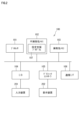
- FIG. 2 is a block diagram illustrating an example of a hardware configuration of the setting assistance device according to the embodiment.
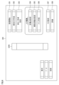
- FIG. 3 is a functional block diagram illustrating an example of functions of the setting assistance device according to the embodiment.
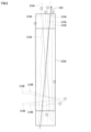
- FIG. 4 is a diagram showing an example of the setting screen.
- FIG. 5 is a diagram showing an example of a display of a movement trajectory.
- FIG. 6 is a diagram for explaining an example of selection of a movement trajectory.
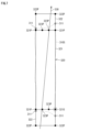
- FIG. 7 is a diagram showing an example of candidate positions of the definition point.
- FIG. 8 is a diagram for explaining the position adjustment of the definition point.
- FIG. 9 is a diagram for explaining the position adjustment of the auxiliary definition point.
- FIG. 1 is a diagram illustrating an example of use of an infrastructure radio wave sensor according to an embodiment.
- FIG. 2 is a block diagram illustrating an example of a hardware configuration of the setting assistance device according to the embodiment
- FIG. 10 is a diagram showing an example of a set detection area.
- FIG. 11 is a diagram for explaining an example of creating a central waiting area.
- FIG. 12 is a diagram showing an example of the created central waiting area.
- FIG. 13 is a flowchart illustrating an example of a setting support operation of an infrastructure radio wave sensor by the setting support device according to the embodiment.
- FIG. 14 is a diagram showing an example of the evaluation screen.
- the radio wave sensor setting support device includes an acquisition unit that acquires the detection results of an object moving across a crosswalk detected by the radio wave sensor, a display control unit that causes a display device to display the movement trajectory of the object in a coordinate space previously set in the radio wave sensor based on the detection results, a designation unit that receives from a user designation of a position in the coordinate space of a definition point that defines a detection area corresponding to the crosswalk based on the movement trajectory displayed on the display device, and a setting unit that sets the detection area in the coordinate space by placing the definition point at the designated position in the coordinate space. This makes it possible to support the user in setting the detection area of the crosswalk in the radio wave sensor.
- the display control unit causes the display device to display the multiple movement trajectories of the multiple objects
- the setting assistance device further includes a selection unit that selects one or more of the multiple movement trajectories displayed on the display device
- the designation unit may receive from the user a designation of the position of the definition point in the coordinate space based on the one or more movement trajectories selected by the selection unit. This allows the user to designate the position of the definition point based on one movement trajectory selected from the multiple movement trajectories.
- the selection unit may receive designation of the one or more movement trajectories from the user, and select the one or more designated movement trajectories. This allows the user to designate one movement trajectory that can be used to set a detection area from among the multiple movement trajectories.
- the selection unit may select one or more of the plurality of movement trajectories based on the movement patterns of the plurality of objects in each of the plurality of movement trajectories. This makes it possible to select a movement trajectory having a specific movement pattern from the plurality of movement trajectories, and to use the selected movement trajectory for setting a detection area.
- the selection unit may select one or more of the multiple movement trajectories based on the radio wave irradiation direction of the radio wave sensor and the direction of each of the multiple movement trajectories. This makes it possible to select a movement trajectory that faces a specific direction with respect to the radio wave irradiation direction from among the multiple movement trajectories, and to use the selected movement trajectory for setting a detection area.
- the display control unit may display the one or more movement trajectories selected by the selection unit and the movement trajectories not selected by the selection unit in different modes. This allows the user to distinguish the selected movement trajectory from other movement trajectories.
- the setting assistance device may further include a determination unit that determines candidate positions in the coordinate space of the definition point based on the movement trajectory and displays the candidate positions on the display device. This allows the user to specify the position of the definition point using the displayed candidate positions.
- the determination unit may determine the candidate positions based on a moving average value of the object's position over time on the movement trajectory. This makes it possible to suppress the influence of errors in the movement trajectory and determine appropriate candidate positions.
- the setting unit may place a plurality of the definition points at a plurality of positions specified in the coordinate space, and set the detection area as a polygon having the plurality of definition points as vertices. This allows the user to set an appropriate detection area by specifying the positions of the definition points.
- the display control unit may display the movement trajectory by superimposing it on an initial area, which is a detection area that is set in advance in the coordinate space. This allows the user to grasp the position of the movement trajectory relative to the detection area that is set in advance.
- the method of supporting radio wave sensor setting includes the steps of acquiring a detection result of an object moving on a crosswalk detected by a radio wave sensor, displaying on a display device a movement trajectory of the object in a coordinate space preset in the radio wave sensor based on the detection result, receiving from a user a designation of a position in the coordinate space of a definition point that defines a detection area corresponding to the crosswalk based on the movement trajectory displayed on the display device, and setting the detection area in the coordinate space by placing the definition point at the designated position in the coordinate space.
- a computer program is a computer program for assisting in the setting of a radio wave sensor that detects objects on a crosswalk, and causes a computer to execute the following steps: acquiring a detection result of an object moving on a crosswalk detected by the radio wave sensor; displaying on a display device a movement trajectory of the object in a coordinate space preset in the radio wave sensor based on the detection result; accepting from a user a designation of a position in the coordinate space of a definition point that defines a detection area corresponding to the crosswalk based on the movement trajectory displayed on the display device; and setting the detection area in the coordinate space by placing the definition point at the designated position in the coordinate space.
- a part or all of the radio wave sensor setting support device can be configured as a semiconductor integrated circuit.
- a system can be configured that includes a part of the radio wave sensor setting support device.
- An infrastructure radio wave sensor 10 is a radio wave radar for monitoring traffic.
- the infrastructure radio wave sensor 10 detects pedestrians on a pedestrian crossing 20.
- the infrastructure radio wave sensor 10 is, for example, a millimeter wave radar.
- the infrastructure radio wave sensor 10 is attached to a structure 50 provided on a road.
- the structure 50 has a height of several meters.
- the infrastructure radio wave sensor 10 is installed at a height of several meters above the ground.
- the structure 50 includes, for example, a pole 51 and an arm 52 provided near the upper end of the pole 51.
- the infrastructure radio wave sensor 10 is attached to the arm 52.
- the infrastructure radio wave sensor 10 detects objects (e.g., pedestrians, bicycles) on the crosswalk 20 by emitting radio waves (millimeter waves) onto the crosswalk 20 and receiving the reflected waves. More specifically, the infrastructure radio wave sensor 10 can detect the distance from the infrastructure radio wave sensor 10 to an object on the crosswalk 20, the speed of the object, and the horizontal angle (azimuth angle) of the object's location relative to the radio wave emission axis.
- objects e.g., pedestrians, bicycles
- radio waves millimeter waves
- the infrastructure radio wave sensor 10 can detect the distance from the infrastructure radio wave sensor 10 to an object on the crosswalk 20, the speed of the object, and the horizontal angle (azimuth angle) of the object's location relative to the radio wave emission axis.
- the infrastructure radio wave sensor 10 is set with a detection area 30, which is a range on the road for detecting objects.
- the detection area 30 is a part of the radio wave irradiation range 40 of the infrastructure radio wave sensor 10.
- the radio wave irradiation range 40 covers the detection area 30.
- the radio wave irradiation range 40 is a range in which an object reflects the radio waves irradiated by the infrastructure radio wave sensor 10 and the infrastructure radio wave sensor 10 can detect the object by the reflected waves from the object.
- the radio wave irradiation range 40 does not have to include a range in which the infrastructure radio wave sensor 10 cannot detect an object even if it can irradiate radio waves.
- the radio wave irradiation range 40 is not limited to this, and may be the entire range in which the infrastructure radio wave sensor 10 can irradiate radio waves.
- a coordinate space for detecting objects is set in the infrastructure radio wave sensor 10.
- the unique coordinate system set in the infrastructure radio wave sensor 10 is also referred to as the "unique coordinate system.”
- the unique coordinate system is an orthogonal coordinate system with an origin at a point on the ground vertically below the infrastructure radio wave sensor 10, and two mutually orthogonal horizontal axes as the X-axis and Y-axis.
- the Y-axis is the intersection line between the ground and a vertical plane including the radio wave irradiation axis of the infrastructure radio wave sensor 10 (the normal direction of the radio wave irradiation surface of the infrastructure radio wave sensor 10).
- the X-axis is an axis perpendicular to the Y-axis.
- the X-axis is an axis parallel to the ground.
- the setting assistance device assists the user (operator) in setting the detection area 30 in the unique coordinate space of the infrastructure radio wave sensor 10.
- the setting support device 100 is used by a user who sets the detection area 30 of the infrastructure radio wave sensor 10.
- the setting support device 100 includes a processor 101, a non-volatile memory 102, a volatile memory 103, an input/output interface (I/O) 104, a graphics controller 105, and a communication interface (communication I/F) 106.
- the setting support device 100 further includes an input device 201 and a display device 202. At least one of the input device 201 and the display device 202 may be an external device connected to the setting support device 100.
- the volatile memory 103 is, for example, a semiconductor memory such as SRAM (Static Random Access Memory) or DRAM (Dynamic Random Access Memory).
- the non-volatile memory 102 is, for example, a flash memory, a hard disk, or a ROM (Read Only Memory).
- the non-volatile memory 102 stores a setting assistance program 107, which is a computer program, and data used to execute the setting assistance program 107. Each function of the setting assistance device 100 is realized by the setting assistance program 107 being executed by the processor 101.
- the setting assistance program 107 can be stored in a recording medium such as a flash memory, a ROM, or a CD-ROM.
- the processor 101 uses the setting assistance program 107 to assist the user in setting the detection area 30 of the infrastructure radio wave sensor 10.
- the processor 101 is, for example, a CPU (Central Processing Unit). However, the processor 101 is not limited to a CPU.
- the processor 101 may be a GPU (Graphics Processing Unit).
- the processor 101 may be, for example, an ASIC (Application Specific Integrated Circuit), or a programmable logic device such as a gate array or FPGA (Field Programmable Gate Array). In this case, the ASIC or programmable logic device is configured to be capable of executing processing similar to that of the setting assistance program 107.
- the input device 201 includes a keyboard and a pointing device such as a mouse.
- the input device 201 may be a capacitive or pressure-sensitive touch pad overlaid on the screen of the display device 202.
- the input device 201 is used to input data to the setting assistance device 100.
- the input/output interface 104 is connected to the input device 201.
- the input/output interface 104 accepts input data from the input device 201 and provides the accepted data to the processor 101.
- the display device 202 includes, for example, a liquid crystal panel or an OEL (organic electroluminescence) panel.
- the display device 202 can display text or graphic information.
- the graphics controller 105 is connected to the display device 202 and controls the display on the display device 202.
- the graphics controller 105 includes, for example, a GPU and a VRAM (Video RAM), stores data to be displayed on the display device 202 in the VRAM, periodically reads one frame of video data from the VRAM, and generates a video signal. The generated video signal is output to the display device 202, and an image is displayed on the display device 202.
- the function of the graphics controller 105 may be included in the processor 101. A portion of the area of the volatile memory 103 may be used as the VRAM.
- the communication I/F 106 can communicate with an external device.
- the communication I/F 106 is connected to the infrastructure radio wave sensor 10 by a communication cable and can communicate with the infrastructure radio wave sensor 10.
- the communication I/F 106 is a wireless communication interface and may be able to communicate with the infrastructure radio wave sensor 10 wirelessly.
- the communication I/F 106 may be able to communicate with the infrastructure radio wave sensor 10 via a wide area communication network.
- the setting assistance device 100 functions as an acquisition unit 110, a display control unit 111, a selection unit 112, a determination unit 113, a designation unit 114, and a setting unit 115.
- the infrastructure radio wave sensor 10 can be set to two operating modes: a setting mode and an operation mode.
- the setting mode is an operating mode for setting a detection area 30 in the infrastructure radio wave sensor 10.
- the operation mode is an operating mode for detecting objects for traffic monitoring after the detection area 30 has been set.
- the infrastructure radio wave sensor 10 When setting the detection area 30, the infrastructure radio wave sensor 10 is started in the setting mode.
- the setting assistance device 100 communicates with the infrastructure radio wave sensor 10 operating in the setting mode and sets the detection area 30.
- the setting assistance device 100 can display a setting screen for setting the detection area 30. See FIG. 4.
- the setting screen 300 includes a start receiving button 301, a create detection area button 302, a height/angle setting button 303, a set definition point button 304, an auxiliary set definition point button 305, a create mesh button 306, a set mask button 307, and an evaluate button 308.
- the start receiving button 301 is a button for starting to receive detection results from the infrastructure radio wave sensor 10.
- the detection results are transmitted from the infrastructure radio wave sensor 10, and the setting assistance device 100 receives the detection results.
- the detection area creation button 302 is a button for creating initial data for the detection area 30.
- the initial data for the detection area 30 may be created at a predetermined position and size in the unique coordinate space, or may be created based on the detection results of the infrastructure radio wave sensor 10.
- the height/angle setting button 303 is a button for setting the installation height from the ground of the infrastructure radio wave sensor 10 and the radio wave irradiation direction.
- the installation height from the ground of the infrastructure radio wave sensor 10 and the radio wave irradiation direction can be input.
- the user can set the installation height and radio wave irradiation direction by inputting the installation height from the ground of the infrastructure radio wave sensor 10 and the radio wave irradiation direction into the setting support device 100 using the input device 201.
- the acquisition unit 110 acquires the detection results of an object moving on the crosswalk from the infrastructure radio wave sensor 10 that is set to the setting mode. That is, the acquisition unit 110 acquires the detection results by receiving them from the infrastructure radio wave sensor 10.
- the display control unit 111 causes the display device 202 to display the movement trajectory of the object in the unique coordinate space based on the detection results acquired by the acquisition unit 110.
- FIG. 5 is a diagram showing an example of the movement trajectory display.
- the movement trajectory 310A extending in the longitudinal direction of the crosswalk (the direction perpendicular to the roadway on which the crosswalk is provided) is, for example, the movement trajectory of a pedestrian or bicycle (hereinafter also referred to as a "crosser") crossing the crosswalk.
- the movement trajectory 310B extending in the width direction of the crosswalk (the direction of the roadway on which the crosswalk is provided) is, for example, the movement trajectory of a vehicle traveling on the roadway.
- the infrastructure radio wave sensor 10 outputs detection results at predetermined time intervals.
- the detection result includes object position information and time information of object detection.
- the display control unit 111 draws the position of the detected object as a point in a unique coordinate space in real time.
- movement trajectories 310A, 310B are formed by a collection of points indicating the position of the same object at each time.
- the display control unit 111 may display the movement trajectories 310A, 310B as lines by connecting points arranged in chronological order with a line.
- the display control unit 111 may display the most recent object detection position using a different graphic than the points or lines that make up the movement trajectory. In the example of FIG. 5, the most recent object detection position is shown using a circular mark. This allows the user to recognize the object's current position.
- the infrastructure radio wave sensor 10 identifies the detected objects and assigns identification information to each object. In other words, the infrastructure radio wave sensor 10 identifies, among the objects detected this time, those that are the same as the object detected last time, based on the position and direction of movement of each object detected last time and the position and direction of movement of each object detected this time. This allows the infrastructure radio wave sensor 10 to track the detected objects.
- the detection result may include identification information of the object.
- the display control unit 111 may display the movement trajectories 310A and 310B as lines by connecting the positions of objects with the same identification information in chronological order with a line.
- the setting assistance device 100 may store the detection results received in advance from the infrastructure radio wave sensor 10 in the non-volatile memory 102, and the acquisition unit 110 may acquire the detection results by reading out the stored detection results. In this way, even if the infrastructure radio wave sensor 10 and the setting assistance device 100 are in a state where they cannot communicate with each other, the user can determine the position, angle, shape, and size of the detection area 30 in the unique coordinate space using the setting assistance device 100, and when the infrastructure radio wave sensor 10 and the setting assistance device 100 are in a state where they can communicate with each other, the determined detection area 30 can be set in the infrastructure radio wave sensor 10.
- the display control unit 111 calculates the moving average value of the position of the same object over a predetermined period of time (e.g., 3 seconds). Specifically, the display control unit 111 saves the positions of objects with the same identification information output from the infrastructure radio wave sensor 10, and sequentially calculates the average value of the positions over the past 3 seconds from the multiple saved positions. The display control unit 111 may display the movement trajectories 310A, 310B by drawing the calculated moving average value of the positions as points.
- a predetermined period of time e.g. 3 seconds
- the movement trajectories 310A and 310B are displayed superimposed on the initial area 320A, which is an initially set detection area. This allows the user to confirm the position, angle, and size of the initial area 320A relative to the movement trajectories 310A and 310B.
- the initial area 320A may be set with a longitudinal direction that is a predetermined direction relative to the radio wave irradiation direction.
- the setting screen 300 may display an arrow 330 indicating the direction of radio wave irradiation, superimposed on the movement trajectories 310A and 310B.
- the designation unit 114 receives from the user the designation of the position in the unique coordinate space of the definition point that defines the detection area 320 based on the movement trajectory of the object displayed on the display device 202.
- the selection unit 112 selects one or more of the movement trajectories of the multiple objects displayed on the display device 202.
- the designation unit 114 can receive, from the user, a designation of the position of the definition point in the inherent coordinate space based on the movement trajectory selected by the selection unit 112.
- the definition point setting button 304 is a button for setting the position of the definition point.
- the position of the definition point in the detection area 320 can be set. For example, when the initial area 320A is displayed, clicking the definition point setting button 304 makes it possible to set the position of the definition point in the initial area 320A. In this state, the user can specify the position of the definition point by using the input device 201.
- the selection unit 112 can accept designation of one or more of the movement trajectories of multiple objects from a user, and select the designated one or more movement trajectories.
- a worker walks in a specific pattern on a crosswalk.
- the worker walks along the outer edge of the crosswalk and stops at the four corners of the crosswalk for a certain period of time (several seconds).
- the movement trajectory of such a worker is rectangular in shape. The user can recognize a movement trajectory that has the same shape as the worker's walking pattern as the movement trajectory of the worker, and select the movement trajectory by clicking on the movement trajectory.
- the selected movement trajectory 310S is displayed in a manner different from the other movement trajectories (non-selected movement trajectories) 310A, 310B.
- the movement trajectory 310S is displayed in a color different from the other movement trajectories 310A, 310B.
- the movement trajectory 310S is displayed with a line type or line thickness different from the movement trajectories 310A, 310B. This allows the user to visually distinguish between the movement trajectory 310S and the movement trajectories 310A, 310B.
- the selection unit 112 may display the most recent object detection position on the movement trajectory 310S using a different graphic than the most recent object detection positions on the movement trajectories 310A and 310B.
- the most recent object detection position on the movement trajectory 310S is shown using a black circular mark
- the most recent object detection positions on the movement trajectories 310A and 310B are shown using a white circular mark.
- the selection unit 112 may display the identification information of the object near the movement trajectory 310S.
- the movement trajectory with the identification information (ID) "10" and the movement trajectory with the ID "20" are selected.
- the selection unit 112 may select one or more of the movement trajectories of the multiple objects based on the movement patterns of the objects in each of the movement trajectories 310A, 310B of the multiple objects. As described above, the worker moves across the crosswalk in a specific pattern. The movement pattern of the worker is registered in advance in the setting assistance device 100, and the selection unit 112 can select a movement trajectory that matches the registered movement pattern from among the movement patterns of the objects detected by the infrastructure radio wave sensor 10.
- the selection unit 112 can select one or more of the movement trajectories of multiple objects based on the radio wave irradiation direction of the infrastructure radio wave sensor 10 and the direction of the movement trajectory. For example, the direction in which the worker walks is registered in advance in the setting assistance device 100, and the selection unit 112 can select a movement trajectory whose movement direction matches the registered movement direction from among the movement trajectories of objects detected by the infrastructure radio wave sensor 10.
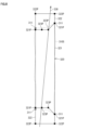
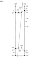
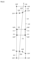
- the determination unit 113 determines candidate positions in the inherent coordinate space of the definition point based on the movement trajectory, and displays the determined candidate positions on the display device 202. See FIG. 7. In the example of FIG. 7, in order to simplify the figure, only the selected movement trajectory 310S is shown, and the unselected movement trajectories 310A and 310B are omitted.
- the detection area 320 includes a zebra area 321, which is a pedestrian crossing area, and a waiting area 322 where pedestrians wait for the traffic light to turn on.
- the waiting areas 322 are provided on both sides of the detection area 320 in the longitudinal direction.
- the definition points 321P are the four vertices of the rectangular zebra area 321.
- the definition points 321P are movable. For example, the user can select the definition point 321P as the target to be moved by clicking on it.
- the definition point 321S selected as the target to be moved is displayed in a different manner from the other definition points (unselected definition points) 321P. In the example of FIG. 7, a dashed frame is drawn around the definition point 321S selected as the target to be moved.
- the user can change the position of definition point 321S by dragging definition point 321S selected as the target to be moved. By adjusting the position of definition point 321S, the user can adjust the position, shape, and size of zebra area 321.
- a worker walks along the outer edge of a crosswalk and stops at each of the four corners for a certain period of time. That is, the worker stops for a certain period of time (for example, five seconds) at one vertex of a rectangular crosswalk, for example, one vertex on the left side of the crosswalk, and then walks along the left edge of the crosswalk toward the opposite bank. When the worker reaches the left vertex of the crosswalk on the opposite bank, he stops for a certain period of time. After that, the worker walks from left to right along the edge of the crosswalk, along the boundary between the crosswalk (roadway) and the sidewalk. When the worker reaches the vertex on the right side of the crosswalk, he stops for a certain period of time.
- a certain period of time for example, five seconds
- the worker then walks along the right edge of the crosswalk, toward the opposite bank. When the worker reaches the vertex on the right side of the crosswalk, he stops for a certain period of time. After that, the worker walks from right to left along the edge of the crosswalk, along the boundary between the crosswalk (roadway) and the sidewalk.
- the determination unit 113 determines the point where the worker stops for a certain period of time as the candidate position.
- the candidate position 311 is shown as a hatched circular mark.
- the determination unit 113 can determine the candidate position 311 based on the moving average value of the object's position over time on the movement trajectory 310S.
- the determination unit 113 can calculate the moving average value of the object's position with a time width equal to the stopping time at a stopping position when a worker walks across a crosswalk in a specific pattern. That is, if the walking pattern of the work vehicle includes stopping for five seconds at each of the four vertices of the crosswalk, the determination unit 113 can set the time width of the moving average value to five seconds. This makes it possible to accurately identify the positions of the four vertices of the crosswalk.
- the candidate positions do not have to be points on the movement trajectory.
- a walking pattern in which the user walks a specified distance (e.g., 50 cm) inside the outer edge of the crosswalk can be registered in advance in the setting assistance device 100.
- the outer edge of the crosswalk is located a specified distance outside the movement trajectory.
- the determination unit 113 can set the outer edge line of the crosswalk outside the movement trajectory by the pre-registered offset amount, and determine the four vertices of the set outer edge line as the candidate positions 311.
- the user can click on the candidate position 311 to specify it as the position to which the definition point 321S is to be moved.
- the specification unit 114 accepts the specification of the candidate position 311 by the user.
- the setting unit 115 sets the detection area 320 in the inherent coordinate space by placing definition points 321S at the specified candidate positions 311 in the inherent coordinate space.
- the setting unit 115 can place multiple definition points 321P at each of the multiple candidate positions 311 specified in the inherent coordinate space, and create the detection area 320 as a polygon with the multiple definition points 321P as vertices.
- the user can select definition point 321S as the target to be moved, and specify candidate position 311 as the position to which definition point 321S should be moved.
- Setting unit 115 changes the position of selected definition point 321S to the specified candidate position 311. As a result, the position of definition point 321S after the change is set to the apex of the crosswalk.
- the position of the definition point 321P at the bottom right of the detection area 320 in FIG. 7 has been changed to the candidate position 311 at the bottom right of the movement trajectory 310S.
- the position of the definition point 321P at the top right of the detection area 320 has been changed to the candidate position 311 at the top right of the movement trajectory 310S.
- the user can change the position of the definition point 321P at the bottom left of the detection area 320 to the candidate position 311 at the bottom left of the movement trajectory 310S.
- the user can change the position of the definition point 321P at the top left of the detection area 320 to the candidate position 311 at the top left of the movement trajectory 310S.
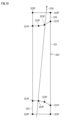
- the detection area 320 includes auxiliary definition points 322P and 323P.
- the auxiliary definition point 322P is a point for defining the waiting area 322
- the auxiliary definition point 323P is a point for defining the shape of the zebra area 321 in detail.
- the corners of the sidewalk may be formed in an arc shape.
- both ends of the crosswalk are curved in an arc shape.
- Auxiliary definition point 323P is placed between definition points 321P at both ends on the boundary between zebra area 321 and waiting area 322.
- Auxiliary definition point 323P is used to make zebra area 321 conform to the shape of such a crosswalk.
- the waiting area 322 is provided by extending a predetermined length in the longitudinal direction from the zebra area 321. Auxiliary definition points 322P are placed at two vertices of the waiting area 322 away from the zebra area 321. The waiting area 322 is defined by two auxiliary definition points 322P and two definition points 321P at both ends of the boundary line between the waiting area 322 and the zebra area 321.
- the auxiliary definition point setting button 305 is a button for setting the positions of the auxiliary definition points 322P, 323P. Once adjustment of the positions of the four definition points 321P is complete, the user can click the auxiliary definition point setting button 305. This makes it possible to set the positions of the auxiliary definition points 322P, 323P. In this state, the user can specify the positions of the auxiliary definition points 322P, 323P by using the input device 201.
- the setting unit 115 can adjust the positions of the auxiliary definition points 322P and 323P. This adjusts the shapes of the zebra area 321 and the waiting area 322.
- the auxiliary definition point 323P can be moved.
- the user can select the auxiliary definition point 323P as the one to be moved by clicking on it.
- the auxiliary definition point 323S selected as the one to be moved is displayed in a different manner from the other auxiliary definition points (unasselected auxiliary definition points) 323P.
- a dashed frame is drawn around the auxiliary definition point 323S selected as the one to be moved.
- the user can change the position of the auxiliary definition point 323S by dragging the auxiliary definition point 323S selected as the target to be moved.
- the user can adjust the position of the auxiliary definition point 323S to match the curved movement trajectory.
- the auxiliary definition point 322P can also be moved.
- the user can select the auxiliary definition point 322P as the one to be moved by clicking on it.
- the auxiliary definition point 322P selected as the one to be moved is displayed in a different manner from the other auxiliary definition points (unasselected auxiliary definition points) 322P.
- a dashed frame is drawn around the auxiliary definition point 323P selected as the one to be moved.
- the user can change the position of the auxiliary definition point 322S by dragging the auxiliary definition point 322S selected as the target to be moved.
- the user can adjust the position of the auxiliary definition point 322S and adjust the position, size, and shape of the waiting area 322.
- Some crosswalks have a median strip.
- the median strip is a safety zone and also a waiting area for pedestrians waiting for the traffic light to turn on.
- the setting assistance device 100 can create an area in the detection area 320 that corresponds to the median strip (hereinafter also referred to as the "central waiting area") in the unique coordinate space.
- a worker walks in a specific pattern in the median strip.
- the worker walks along the outer edge of the median strip and stops at the four corners of the median strip for a certain period of time (several seconds).
- Such a worker's movement trajectory 312 has a rectangular shape. The user can recognize a movement trajectory 312 that has the same shape as the worker's walking pattern as the worker's movement trajectory, and select the movement trajectory 312 by clicking on the movement trajectory 312.
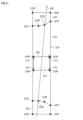
- the setting assistance device 100 can initially set the central waiting area and superimpose the initially set central waiting area 324 on the movement trajectory 312.
- Auxiliary definition points 324P are placed at multiple vertices of the central waiting area 324.
- the auxiliary definition points 324P are points used to define the central waiting area 324.
- the designation unit 114 accepts, from the user, a designation of the position of the auxiliary definition point 324P in the inherent coordinate space based on the movement trajectory 312 of the object displayed on the display device 202.
- the designation unit 114 can accept, from the user, a designation of the position of the auxiliary definition point 324P in the inherent coordinate space based on the movement trajectory 312 selected by the selection unit 112.
- the determination unit 113 determines a candidate position in the inherent coordinate space of the auxiliary definition point 324P based on the movement trajectory, and displays the determined candidate position on the display device 202.
- the selected movement trajectory 312 is shown, and the unselected movement trajectories are omitted.
- the auxiliary definition point 324P can be moved.
- the user can select the auxiliary definition point 324P as the one to be moved by clicking on it.
- the auxiliary definition point 324S selected as the one to be moved is displayed in a different manner from the other definition points (unselected definition points) 324P. For example, a dashed frame is drawn around the auxiliary definition point 324S selected as the one to be moved.
- the user can change the position of the auxiliary definition point 324S by dragging the auxiliary definition point 324S selected as the target to be moved. By adjusting the position of the auxiliary definition point 324S, the user can adjust the position, shape, and size of the central waiting area 324.
- a worker walks along the outer edge of a median strip and stops at each of the four corners for a certain period of time.
- the determination unit 113 determines the point where the worker stopped for the certain period of time as a candidate position.
- the candidate position 313 is shown as a hatched circular mark.
- the determination unit 113 can determine the candidate position 313 based on the moving average value of the object's position over time on the movement trajectory 310S.
- the determination unit 113 can calculate the moving average value of the object's position with a time width equal to the stopping time at a stopping position when a worker walks in a specific pattern on the median strip. That is, if the walking pattern of the work vehicle includes stopping for five seconds at each of the four vertices of the median strip, the determination unit 113 can set the time width of the moving average value to five seconds. This makes it possible to accurately identify the positions of the four vertices of the median strip.
- the user can click on the candidate position 313 to specify it as the position to which the auxiliary definition point 324S is to be moved.
- the specification unit 114 accepts the specification of the candidate position 313 by the user.
- the setting unit 115 sets the central waiting area 324 in the inherent coordinate space by placing auxiliary definition points 324S at the specified candidate positions 313 in the inherent coordinate space.
- the setting unit 115 can place multiple auxiliary definition points 324P at each of the multiple candidate positions 313 specified in the inherent coordinate space, and create the central waiting area 324 as a polygon with the multiple auxiliary definition points 324P as vertices.
- auxiliary definition point 324S as the target to be moved, and specify candidate position 313 as the position to which auxiliary definition point 324S should be moved.
- the setting unit 115 changes the position of the selected auxiliary definition point 324S to the specified candidate position 313.
- the position of auxiliary definition point 324S is set to the apex of the median strip.
- the central waiting area 324 can be created to match the actual position, shape, and size of the median strip.
- the mesh creation button 306 is a button for displaying the detection area 320 in a mesh.
- the setting screen 300 switches to a mesh display of the detection area 320.
- the detection area 320 is divided into a grid of rectangular areas of a specific size.
- each rectangular area is color-coded according to the number of passing objects, the average speed of the passing objects, or the moving direction of the passing objects.
- the user can use the mesh display to evaluate whether the created detection area 320 is appropriate.
- the mask setting button 307 is a button for creating a mask area that is excluded from detection targets. Stationary objects such as traffic light poles and objects that are constantly detected such as plants can cause erroneous detection of pedestrians crossing the road.
- the setting screen 300 transitions to a state in which a mask area can be created. In this state, the user can place a mask area in the unique coordinate space at the position of an object that is constantly detected.
- the evaluation button 308 is a button for the user to evaluate the created detection area 320.
- the setting screen 300 transitions to an evaluation screen where the detection area 320 can be evaluated.
- the detection result is received from the infrastructure radio wave sensor 10, and the object's movement trajectory is superimposed on the detection area 320 on the evaluation screen.
- the user visually checks the crossing state of the pedestrian at the actual crosswalk, and compares it with the movement trajectory and the detection area 320 displayed on the display device 202 to evaluate whether the detection area 320 has been created correctly.
- the user can input an instruction to execute the setting of the infrastructure radio wave sensor 10 using the created detection area 320.
- the user inputs an instruction to execute the setting, information on the detection area 320 is transmitted to the infrastructure radio wave sensor 10, and the detection area 320 is set in the infrastructure radio wave sensor 10.
- the setting mode is completed.
- the infrastructure radio wave sensor 10 is started in the operation mode and detects objects using the set detection area 320.
- the processor 101 of the setting assistance device 100 displays the setting screen 300 on the display device 202 and starts the infrastructure radio wave sensor 10 in setting mode (step S101).
- the detection results are transmitted from the infrastructure radio wave sensor 10.
- the setting assistance device 100 receives the detection results transmitted from the infrastructure radio wave sensor 10 (step S102).
- the processor 101 When the user clicks the detection area creation button 302, the processor 101 initializes the detection area 320 (step S103).
- the setting assistance device 100 enters a state in which the installation height and installation angle (radio wave irradiation direction) of the infrastructure radio wave sensor 10 can be input.
- the processor 101 receives input from the user of the installation height and radio wave irradiation direction of the infrastructure radio wave sensor 10, and sets the input installation height and radio wave irradiation direction (step S104).
- Object movement trajectories 310A and 310B are displayed on the setting screen 300.
- the processor 101 selects one or more of the movement trajectories 310A and 310B (step S105).
- the processor 101 may select the movement trajectory clicked by the user, may select a movement trajectory that matches a specific pattern registered in advance, or may select a movement trajectory based on the radio wave irradiation method.
- the processor 101 determines candidate positions of the definition point from the selected movement trajectory (step S106).
- the user specifies a candidate location by clicking on the candidate location.
- the processor 101 accepts the candidate location specification from the user (step S107).
- the user selects a definition point by clicking on the definition point.
- the processor 101 accepts the selection of the definition point 321P from the user (step S108).
- the processor 101 changes the position of the selected definition point 321S to the specified candidate position 311 (step S109).
- the processor 101 determines whether the positions of all four definition points 321P have been determined (step S110). If there are any definition points 321P whose positions have not been determined (NO in step S110), the processor 101 returns to step S107. This allows the positions of the remaining definition points 321P to be determined.
- the processor 101 adjusts the positions of the auxiliary definition points 322P, 323P, and 324P (step S111).
- the positions of the auxiliary definition points 322P, 323P, and 324P are adjusted by user operation.
- the position of the auxiliary definition point 324P in the central waiting area 324 may be adjusted to a candidate position determined from the movement trajectory of the worker in the central median strip.
- the processor 101 displays the created detection area 320 on the display device 202 so that the user can confirm and evaluate the detection area 320. For example, when the user clicks the mesh creation button 306, the processor 101 displays the detection area 320 as a mesh, and when the user clicks the evaluation button 308, the processor 101 displays the detection area 320 superimposed on the object's movement trajectory. The user confirms the created detection area 320 on the screen and evaluates the detection area 320 (step S112).
- the user If the user approves of the created detection area 320, the user inputs an instruction to execute the setting of the detection area 320 in the infrastructure radio wave sensor 10.
- the processor 101 receives the instruction to execute the setting from the user, it transmits data of the detection area 320 to the infrastructure radio wave sensor 10 and sets the detection area in the infrastructure radio wave sensor 10 (step S113). This ends the setting support operation of the infrastructure radio wave sensor.
- the setting of the infrastructure radio wave sensor can be achieved with less manpower and shorter working hours.
- the position, shape, etc. of the road around the crosswalk may be displayed on an evaluation screen for evaluating the created detection area 320.
- FIG. 14 is a diagram showing an example of the evaluation screen.
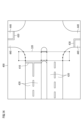
- the setting assistance device 100 can estimate the positions of the stop line 410 and the lane 420 on the roadway intersecting the crosswalk from the movement trajectory of the vehicle, and superimpose the estimated stop line 410 and the lane 420 on the detection area 320 on the evaluation screen 400.
- the setting assistance device 100 may estimate the positions of the stop line 430 and the lane 440 on the roadway parallel to the crosswalk from the movement trajectory of the vehicle, and display the estimated stop line 430 and the lane 440. This allows the position of the detection area 320 to be evaluated more accurately.
- the definition points 321P are the four vertices of the zebra area 321, but this is not limited to this.
- the definition points may be points that are a predetermined length inside or outside from the vertices of the zebra area of a polygon (particularly a rectangle) in at least one of the longitudinal and width directions of the detection area 320.
- the definition points may be vertices of the detection area 320 (i.e., an area including the zebra area 321 and the waiting area 322), or points that are a predetermined length inside or outside from the vertices of the detection area 320 in at least one of the longitudinal and width directions of the detection area 320.
- the definition points do not have to be determined based on the vertices of the zebra area 321 or the detection area 320.
- the definition points may be the midpoints of each side of the zebra area 321 or the detection area 320, or points that are a predetermined length inside or outside from each midpoint in at least one of the longitudinal and width directions of the detection area 320. In this way, any point that can define the detection area 320 can be used as the definition point, as long as it has an arbitrary positional relationship with respect to the detection area 320.
Landscapes
- Engineering & Computer Science (AREA)
- Radar, Positioning & Navigation (AREA)
- Remote Sensing (AREA)
- Physics & Mathematics (AREA)
- General Physics & Mathematics (AREA)
- Computer Networks & Wireless Communication (AREA)
- Electromagnetism (AREA)
- Traffic Control Systems (AREA)
Priority Applications (1)
| Application Number | Priority Date | Filing Date | Title |
|---|---|---|---|
| JP2024562687A JPWO2024122371A1 (cg-RX-API-DMAC7.html) | 2022-12-05 | 2023-11-27 |
Applications Claiming Priority (2)
| Application Number | Priority Date | Filing Date | Title |
|---|---|---|---|
| JP2022-194311 | 2022-12-05 | ||
| JP2022194311 | 2022-12-05 |
Publications (1)
| Publication Number | Publication Date |
|---|---|
| WO2024122371A1 true WO2024122371A1 (ja) | 2024-06-13 |
Family
ID=91379245
Family Applications (1)
| Application Number | Title | Priority Date | Filing Date |
|---|---|---|---|
| PCT/JP2023/042285 Ceased WO2024122371A1 (ja) | 2022-12-05 | 2023-11-27 | 電波センサの設定支援装置、電波センサの設定支援方法、及びコンピュータプログラム |
Country Status (2)
| Country | Link |
|---|---|
| JP (1) | JPWO2024122371A1 (cg-RX-API-DMAC7.html) |
| WO (1) | WO2024122371A1 (cg-RX-API-DMAC7.html) |
Cited By (2)
| Publication number | Priority date | Publication date | Assignee | Title |
|---|---|---|---|---|
| WO2026028665A1 (ja) * | 2024-07-30 | 2026-02-05 | 住友電気工業株式会社 | 電波センサの設定支援装置、電波センサの設定支援方法、及びコンピュータプログラム |
| WO2026053775A1 (ja) * | 2024-09-03 | 2026-03-12 | 住友電気工業株式会社 | 電波センサ、電波センサの設定支援方法、及びコンピュータプログラム |
Citations (4)
| Publication number | Priority date | Publication date | Assignee | Title |
|---|---|---|---|---|
| JP2016003938A (ja) * | 2014-06-17 | 2016-01-12 | 住友電気工業株式会社 | 電波センサ、検知方法および検知プログラム |
| JP2016116137A (ja) * | 2014-12-16 | 2016-06-23 | キヤノン株式会社 | 画像処理装置、画像処理方法、及び、プログラム |
| JP2017090078A (ja) * | 2015-11-04 | 2017-05-25 | 住友電気工業株式会社 | 電波センサ、検知方法および検知プログラム |
| JP2020155089A (ja) * | 2019-03-12 | 2020-09-24 | グローリー株式会社 | エリア設定支援装置、エリア設定支援方法及びエリア設定支援プログラム |
-
2023
- 2023-11-27 WO PCT/JP2023/042285 patent/WO2024122371A1/ja not_active Ceased
- 2023-11-27 JP JP2024562687A patent/JPWO2024122371A1/ja active Pending
Patent Citations (4)
| Publication number | Priority date | Publication date | Assignee | Title |
|---|---|---|---|---|
| JP2016003938A (ja) * | 2014-06-17 | 2016-01-12 | 住友電気工業株式会社 | 電波センサ、検知方法および検知プログラム |
| JP2016116137A (ja) * | 2014-12-16 | 2016-06-23 | キヤノン株式会社 | 画像処理装置、画像処理方法、及び、プログラム |
| JP2017090078A (ja) * | 2015-11-04 | 2017-05-25 | 住友電気工業株式会社 | 電波センサ、検知方法および検知プログラム |
| JP2020155089A (ja) * | 2019-03-12 | 2020-09-24 | グローリー株式会社 | エリア設定支援装置、エリア設定支援方法及びエリア設定支援プログラム |
Cited By (2)
| Publication number | Priority date | Publication date | Assignee | Title |
|---|---|---|---|---|
| WO2026028665A1 (ja) * | 2024-07-30 | 2026-02-05 | 住友電気工業株式会社 | 電波センサの設定支援装置、電波センサの設定支援方法、及びコンピュータプログラム |
| WO2026053775A1 (ja) * | 2024-09-03 | 2026-03-12 | 住友電気工業株式会社 | 電波センサ、電波センサの設定支援方法、及びコンピュータプログラム |
Also Published As
| Publication number | Publication date |
|---|---|
| JPWO2024122371A1 (cg-RX-API-DMAC7.html) | 2024-06-13 |
Similar Documents
| Publication | Publication Date | Title |
|---|---|---|
| KR101843866B1 (ko) | 라이다 데이터를 이용하여 도로 영역과 차선을 검출하는 방법 및 그 시스템 | |
| JP7283005B2 (ja) | 点群データ処理方法および点群データ処理装置 | |
| CN111402387B (zh) | 从用于导航自主车辆的高清晰度地图的点云中移除短时点 | |
| KR101294956B1 (ko) | 지도 데이터 베이스 생성 시스템 | |
| US12601836B2 (en) | Radio-wave sensor installation assistance device, computer program, and radio-wave sensor installation position determination method | |
| US11940557B2 (en) | Object detection device, object detection system, and object detection method | |
| JP2022532695A (ja) | 画像分析に基づく車両ナビゲーションのためのシステム及び方法 | |
| JP4356573B2 (ja) | レーダの設置情報の確認画面と調整画面の表示方法 | |
| CN107111742A (zh) | 在导航中对车道限制和施工区域的识别和预测 | |
| US20240192312A1 (en) | Display device, computer program, and setting method | |
| CN113085899A (zh) | 视野盲区预警方法、装置、设备及存储介质 | |
| US12597341B2 (en) | Installation support device for radio wave sensor, computer program, method of determining installation position of radio wave sensor, and method of supporting installation of radio wave sensor | |
| KR20190056775A (ko) | 차량의 객체 인식 장치 및 방법 | |
| CN112988922A (zh) | 感知地图构建方法、装置、计算机设备和存储介质 | |
| CN113071522A (zh) | 无人驾驶车辆的控制方法及控制装置、无人驾驶车辆 | |
| KR102568111B1 (ko) | 도로 경계 추출 장치 및 방법 | |
| JPWO2024122371A5 (cg-RX-API-DMAC7.html) | ||
| CN114905506A (zh) | 一种基于视觉感知和空间认知神经机制的机器人导航系统 | |
| US20250095482A1 (en) | Display apparatus and non-transitory computer-readable storage medium storing a computer program | |
| WO2026028665A1 (ja) | 電波センサの設定支援装置、電波センサの設定支援方法、及びコンピュータプログラム | |
| WO2025018074A1 (ja) | 電波センサの設定支援装置、電波センサの設定支援方法、及びコンピュータプログラム | |
| JP2023033928A (ja) | 処理装置、インフラ電波センサ、設定システム、インフラ電波センサの設定方法、及びコンピュータプログラム | |
| WO2025254021A1 (ja) | 電波センサの設定支援装置、電波センサの設定支援方法、及びコンピュータプログラム | |
| CN121540170B (zh) | 一种融合激光雷达与相机语义的导盲机器人路径规划方法及系统 | |
| WO2025254019A1 (ja) | 設定支援装置、設定支援方法、およびコンピュータプログラム |
Legal Events
| Date | Code | Title | Description |
|---|---|---|---|
| 121 | Ep: the epo has been informed by wipo that ep was designated in this application |
Ref document number: 23900488 Country of ref document: EP Kind code of ref document: A1 |
|
| WWE | Wipo information: entry into national phase |
Ref document number: 2024562687 Country of ref document: JP |
|
| NENP | Non-entry into the national phase |
Ref country code: DE |
|
| 122 | Ep: pct application non-entry in european phase |
Ref document number: 23900488 Country of ref document: EP Kind code of ref document: A1 |