WO2024122291A1 - 電池モジュール、および、電池スタック - Google Patents
電池モジュール、および、電池スタック Download PDFInfo
- Publication number
- WO2024122291A1 WO2024122291A1 PCT/JP2023/041107 JP2023041107W WO2024122291A1 WO 2024122291 A1 WO2024122291 A1 WO 2024122291A1 JP 2023041107 W JP2023041107 W JP 2023041107W WO 2024122291 A1 WO2024122291 A1 WO 2024122291A1
- Authority
- WO
- WIPO (PCT)
- Prior art keywords
- wall
- battery cell
- battery
- target
- side wall
- Prior art date
- Legal status (The legal status is an assumption and is not a legal conclusion. Google has not performed a legal analysis and makes no representation as to the accuracy of the status listed.)
- Ceased
Links
Images










Classifications
-
- H—ELECTRICITY
- H01—ELECTRIC ELEMENTS
- H01M—PROCESSES OR MEANS, e.g. BATTERIES, FOR THE DIRECT CONVERSION OF CHEMICAL ENERGY INTO ELECTRICAL ENERGY
- H01M50/00—Constructional details or processes of manufacture of the non-active parts of electrochemical cells other than fuel cells, e.g. hybrid cells
- H01M50/20—Mountings; Secondary casings or frames; Racks, modules or packs; Suspension devices; Shock absorbers; Transport or carrying devices; Holders
- H01M50/204—Racks, modules or packs for multiple batteries or multiple cells
- H01M50/207—Racks, modules or packs for multiple batteries or multiple cells characterised by their shape
- H01M50/209—Racks, modules or packs for multiple batteries or multiple cells characterised by their shape adapted for prismatic or rectangular cells
-
- H—ELECTRICITY
- H01—ELECTRIC ELEMENTS
- H01M—PROCESSES OR MEANS, e.g. BATTERIES, FOR THE DIRECT CONVERSION OF CHEMICAL ENERGY INTO ELECTRICAL ENERGY
- H01M10/00—Secondary cells; Manufacture thereof
- H01M10/60—Heating or cooling; Temperature control
- H01M10/64—Heating or cooling; Temperature control characterised by the shape of the cells
- H01M10/647—Prismatic or flat cells, e.g. pouch cells
-
- H—ELECTRICITY
- H01—ELECTRIC ELEMENTS
- H01M—PROCESSES OR MEANS, e.g. BATTERIES, FOR THE DIRECT CONVERSION OF CHEMICAL ENERGY INTO ELECTRICAL ENERGY
- H01M50/00—Constructional details or processes of manufacture of the non-active parts of electrochemical cells other than fuel cells, e.g. hybrid cells
- H01M50/20—Mountings; Secondary casings or frames; Racks, modules or packs; Suspension devices; Shock absorbers; Transport or carrying devices; Holders
- H01M50/218—Mountings; Secondary casings or frames; Racks, modules or packs; Suspension devices; Shock absorbers; Transport or carrying devices; Holders characterised by the material
- H01M50/22—Mountings; Secondary casings or frames; Racks, modules or packs; Suspension devices; Shock absorbers; Transport or carrying devices; Holders characterised by the material of the casings or racks
- H01M50/222—Inorganic material
- H01M50/224—Metals
-
- H—ELECTRICITY
- H01—ELECTRIC ELEMENTS
- H01M—PROCESSES OR MEANS, e.g. BATTERIES, FOR THE DIRECT CONVERSION OF CHEMICAL ENERGY INTO ELECTRICAL ENERGY
- H01M50/00—Constructional details or processes of manufacture of the non-active parts of electrochemical cells other than fuel cells, e.g. hybrid cells
- H01M50/20—Mountings; Secondary casings or frames; Racks, modules or packs; Suspension devices; Shock absorbers; Transport or carrying devices; Holders
- H01M50/244—Secondary casings; Racks; Suspension devices; Carrying devices; Holders characterised by their mounting method
-
- H—ELECTRICITY
- H01—ELECTRIC ELEMENTS
- H01M—PROCESSES OR MEANS, e.g. BATTERIES, FOR THE DIRECT CONVERSION OF CHEMICAL ENERGY INTO ELECTRICAL ENERGY
- H01M50/00—Constructional details or processes of manufacture of the non-active parts of electrochemical cells other than fuel cells, e.g. hybrid cells
- H01M50/20—Mountings; Secondary casings or frames; Racks, modules or packs; Suspension devices; Shock absorbers; Transport or carrying devices; Holders
- H01M50/249—Mountings; Secondary casings or frames; Racks, modules or packs; Suspension devices; Shock absorbers; Transport or carrying devices; Holders specially adapted for aircraft or vehicles, e.g. cars or trains
-
- H—ELECTRICITY
- H01—ELECTRIC ELEMENTS
- H01M—PROCESSES OR MEANS, e.g. BATTERIES, FOR THE DIRECT CONVERSION OF CHEMICAL ENERGY INTO ELECTRICAL ENERGY
- H01M50/00—Constructional details or processes of manufacture of the non-active parts of electrochemical cells other than fuel cells, e.g. hybrid cells
- H01M50/20—Mountings; Secondary casings or frames; Racks, modules or packs; Suspension devices; Shock absorbers; Transport or carrying devices; Holders
- H01M50/262—Mountings; Secondary casings or frames; Racks, modules or packs; Suspension devices; Shock absorbers; Transport or carrying devices; Holders with fastening means, e.g. locks
- H01M50/264—Mountings; Secondary casings or frames; Racks, modules or packs; Suspension devices; Shock absorbers; Transport or carrying devices; Holders with fastening means, e.g. locks for cells or batteries, e.g. straps, tie rods or peripheral frames
-
- H—ELECTRICITY
- H01—ELECTRIC ELEMENTS
- H01M—PROCESSES OR MEANS, e.g. BATTERIES, FOR THE DIRECT CONVERSION OF CHEMICAL ENERGY INTO ELECTRICAL ENERGY
- H01M50/00—Constructional details or processes of manufacture of the non-active parts of electrochemical cells other than fuel cells, e.g. hybrid cells
- H01M50/20—Mountings; Secondary casings or frames; Racks, modules or packs; Suspension devices; Shock absorbers; Transport or carrying devices; Holders
- H01M50/289—Mountings; Secondary casings or frames; Racks, modules or packs; Suspension devices; Shock absorbers; Transport or carrying devices; Holders characterised by spacing elements or positioning means within frames, racks or packs
-
- H—ELECTRICITY
- H01—ELECTRIC ELEMENTS
- H01M—PROCESSES OR MEANS, e.g. BATTERIES, FOR THE DIRECT CONVERSION OF CHEMICAL ENERGY INTO ELECTRICAL ENERGY
- H01M50/00—Constructional details or processes of manufacture of the non-active parts of electrochemical cells other than fuel cells, e.g. hybrid cells
- H01M50/30—Arrangements for facilitating escape of gases
- H01M50/35—Gas exhaust passages comprising elongated, tortuous or labyrinth-shaped exhaust passages
- H01M50/358—External gas exhaust passages located on the battery cover or case
-
- H—ELECTRICITY
- H01—ELECTRIC ELEMENTS
- H01M—PROCESSES OR MEANS, e.g. BATTERIES, FOR THE DIRECT CONVERSION OF CHEMICAL ENERGY INTO ELECTRICAL ENERGY
- H01M50/00—Constructional details or processes of manufacture of the non-active parts of electrochemical cells other than fuel cells, e.g. hybrid cells
- H01M50/50—Current conducting connections for cells or batteries
- H01M50/502—Interconnectors for connecting terminals of adjacent batteries; Interconnectors for connecting cells outside a battery casing
- H01M50/507—Interconnectors for connecting terminals of adjacent batteries; Interconnectors for connecting cells outside a battery casing comprising an arrangement of two or more busbars within a container structure, e.g. busbar modules
-
- H—ELECTRICITY
- H01—ELECTRIC ELEMENTS
- H01M—PROCESSES OR MEANS, e.g. BATTERIES, FOR THE DIRECT CONVERSION OF CHEMICAL ENERGY INTO ELECTRICAL ENERGY
- H01M2220/00—Batteries for particular applications
- H01M2220/20—Batteries in motive systems, e.g. vehicle, ship, plane
-
- Y—GENERAL TAGGING OF NEW TECHNOLOGICAL DEVELOPMENTS; GENERAL TAGGING OF CROSS-SECTIONAL TECHNOLOGIES SPANNING OVER SEVERAL SECTIONS OF THE IPC; TECHNICAL SUBJECTS COVERED BY FORMER USPC CROSS-REFERENCE ART COLLECTIONS [XRACs] AND DIGESTS
- Y02—TECHNOLOGIES OR APPLICATIONS FOR MITIGATION OR ADAPTATION AGAINST CLIMATE CHANGE
- Y02E—REDUCTION OF GREENHOUSE GAS [GHG] EMISSIONS, RELATED TO ENERGY GENERATION, TRANSMISSION OR DISTRIBUTION
- Y02E60/00—Enabling technologies; Technologies with a potential or indirect contribution to GHG emissions mitigation
- Y02E60/10—Energy storage using batteries
Definitions
- the disclosures herein relate to battery modules.
- Patent Document 1 describes a battery stack comprising multiple battery cells and a resin frame.
- a resin frame is disposed between adjacent battery cells.
- the resin frame comprises a main body and side walls provided at both longitudinal ends of the main body and projecting from the side ends of the main body.
- One of the side walls is provided with a lip portion facing the other side wall. The lip portion urges the battery cells towards the other side of the side wall.
- the side walls extend in one direction along the longitudinal end of the battery cell.
- the side walls provided with a lip portion extend in one direction along the longitudinal end of the battery cell, at a distance from the battery cell in the longitudinal direction by the amount of the lip portion.
- the size of the plastic frame has increased by the amount of the lip portion.
- the objective of this disclosure is to provide a battery module and a battery stack that have a holding structure that limits increases in size.
- a battery module includes: A rectangular battery cell that is flat in the thickness direction; a frame for holding the battery cells;
- the frame is a plate-shaped main body wall overlapping the battery cell in a thickness direction; a pair of opposing walls provided at both ends of the main body wall in a direction different from the thickness direction and extending in the thickness direction so as to face the battery cells; a biasing portion that is provided on an inner surface of at least one of the pair of opposing walls and extends toward the battery cell to bias the battery cell;
- the target wall on which the urging portion is provided has a recessed portion that is locally recessed so as to move away from the battery cell at the location where the urging portion is provided.
- the area where the biasing portion is provided is locally recessed away from the battery cell, preventing the frame from increasing in size. It is now possible to provide a battery module with a frame that prevents an increase in size.
- a battery stack includes: a plurality of battery modules each including a rectangular battery cell that is flat in a thickness direction and a frame that holds the battery cell, the battery module being stacked in a thickness direction; A bus bar electrically connected to the plurality of battery cells; a bus bar retaining wall that retains the bus bar;
- the frame is a plate-shaped main body wall overlapping the battery cell in a thickness direction; a pair of opposing walls provided at both ends of the main body wall in a direction different from the thickness direction and extending in the thickness direction so as to face the battery cells; a biasing portion that is provided on an inner surface of at least one of the pair of opposing walls and extends toward the battery cell to bias the battery cell;
- the target wall on which the urging portion is provided has a recessed portion that is locally recessed so as to move away from the battery cell at the location where the urging portion is provided.
- the area where the biasing portion is provided is locally recessed away from the battery cell, which helps prevent the frame from increasing in size. It is now possible to provide a battery stack with a frame that keeps the size of the frame from increasing.
- FIG. 2 is a plan view of the battery stack of the first embodiment.
- FIG. 2 is a plan view of the battery stack of FIG. 1 with a bus bar case removed.
- FIG. 2 is a cross-sectional view of the battery stack of the first embodiment.
- FIG. 2 is a perspective view of a battery module according to the first embodiment.
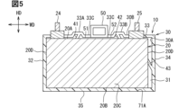
- FIG. 2 is a cross-sectional view of the battery module of the first embodiment.
- FIG. 4 is an enlarged schematic view of a biasing portion.
- 7 is a cross-sectional view of the battery module taken along line VII-VII shown in FIG. 6.
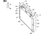
- FIG. 13 is a perspective view of a battery module according to a second embodiment.
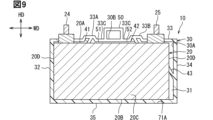
- FIG. 6 is a cross-sectional view of a battery module according to a second embodiment.
- FIG. 11 is a cross-sectional view of a battery module according to a third embodiment.
- FIG. 11 is a cross-sectional view of a battery module according to a third embodiment.
- FIG. 13 is a cross-sectional view of a battery module according to a fourth embodiment.
- FIG. 13 is a cross-sectional view of a battery module according to a fifth embodiment.
- FIG. 13 is a cross-sectional view of a battery module according to a sixth embodiment.
- FIG. 13 is a cross-sectional view of a battery module according to a seventh embodiment.
- FIG. 2 is a schematic diagram showing an example of an embodiment of a recessed portion.
- FIG. 2 is a schematic diagram showing an example of an embodiment of a recessed portion.
- FIG. 2 is a schematic diagram showing an example of an embodiment of a recessed portion.
- FIG. 2 is a schematic diagram showing an example of an embodiment of a recessed portion.
- FIG. 2 is a schematic diagram showing an example of an embodiment of a recessed portion.
- FIG. 2 is a schematic diagram showing an example of an embodiment of a recessed portion.
- 5A and 5B are schematic diagrams illustrating an example of an embodiment of a biasing portion.
- 5A and 5B are schematic diagrams illustrating an example of an embodiment of a biasing portion.
- 5A and 5B are schematic diagrams illustrating an example of an embodiment of a biasing portion.
- 5A and 5B are schematic diagrams illustrating an example of an embodiment of a biasing portion.
- 5A and 5B are schematic diagrams illustrating an example of an embodiment of a biasing portion.
- 5A and 5B are schematic diagrams illustrating an example of an embodiment of a biasing portion.
- 5A and 5B are schematic diagrams illustrating an example of an embodiment of a biasing portion.
- FIG. 1 show schematic configurations of the battery stack 100.
- Figures 4 to 7 show schematic configurations of the battery module 10.
- the battery stack 100 of the embodiment is applied to an electric vehicle such as an electric vehicle or a plug-in hybrid vehicle.
- the electric vehicle may be simply referred to as a vehicle.
- the width direction of the battery cell 20 may be referred to as the width direction WD.
- the height direction of the battery cell 20 may be referred to as the height direction HD.
- the thickness direction of the battery cell 20 may be referred to as the thickness direction TD.
- the width direction WD, height direction HD, and thickness direction TD are mutually orthogonal.
- the width direction WD may be simply referred to as "WD”.
- the height direction HD may be simply referred to as "HD”.
- the thickness direction TD may be simply referred to as "TD”.
- Figure 1 is a plan view of the battery stack 100 of the first embodiment.
- Figure 2 is a plan view of the battery stack 100 of Figure 1 with the bus bar case 90 removed. Note that the dashed line in Figure 1 is shown in the same position in Figure 2.
- Figure 3 is a cross-sectional view of the battery stack 100 of the first embodiment.
- Figure 4 is a perspective view of the battery module 10 of the first embodiment.
- Figure 5 is a cross-sectional view of the battery module 10 of the first embodiment.
- Figure 6 is a schematic diagram in which the biasing portion 40 is enlarged.
- Figure 7 is a cross-sectional view of the battery module 10 along the line VII-VII shown in Figure 5.
- FIG. 1 shows a battery stack 100.
- a plurality of battery stacks 100 are mounted on a vehicle.
- the plurality of battery stacks 100 are connected in series or in parallel by a wire harness or the like. This constitutes an on-board power supply.
- the on-board power supply serves to supply power to an electrical load of the vehicle. Note that the on-board power supply may be constituted by a single battery stack 100.
- the battery stack 100 and the vehicle's smoke exhaust hose 110 are arranged side by side.
- the smoke exhaust hose 110 extends to the outside of the vehicle. Gas generated from the multiple battery cells 20 flows into this smoke exhaust hose 110. The gas is then exhausted to the outside from the smoke exhaust hose 110.
- the on-board power supply can be located appropriately in, for example, the space under the front seats, the space under the rear seats, or the space between the rear seats and the trunk.
- the battery stack 100 has a plurality of battery modules 10, a busbar module 60, and a battery case 70.
- the battery module 10 has battery cells 20 and a resin frame 30.
- the battery cells 20 are held by the resin frame 30.
- the resin frame 30 is formed using an electrically insulating material such as resin.
- the resin frame 30 has a frame structure capable of holding the battery cells 20. Details of the resin frame 30 will be explained later.
- the battery stack 100 is made up of a plurality of stacked battery cells 20.
- the plurality of battery cells 20 are stored in the battery case 70 in a stacked state in the thickness direction TD.
- Battery case 70 has a case bottom wall 71 and case side walls 72. Case bottom wall 71 and case side walls 72 are integrally connected. Case bottom wall 71 and case side walls 72 are formed of an electrically insulating resin material. Case bottom wall 71 has a thin flat shape with a thickness in the height direction HD. Case bottom wall 71 has an inner bottom surface 71A spaced apart from each other in the height direction HD and an outer bottom surface on the back side thereof. Case side walls 72 stand upright in the height direction HD from inner bottom surface 71A. Case side walls 72 extend along the edge of inner bottom surface 71A and form a ring shape in the circumferential direction around the height direction HD. Case bottom wall 71 and case side walls 72 form the storage space of battery case 70.
- Multiple battery modules 10 are stored in the storage space of a battery case 70.
- the battery case 70 is box-shaped with an opening in the height direction HD. Multiple battery modules 10 are stored in the battery case 70 so that the electrode surface 20A of each battery cell 20 corresponds to the opening side.
- the battery cells 20 are stacked in the thickness direction TD so that the main surfaces 20C overlap each other.
- the battery cells 20 have positive terminals 24 and negative terminals 25 that protrude in the height direction HD at both ends in the width direction WD.
- the battery cells 20 are stacked in the width direction WD so that the positive terminals 24 and negative terminals 25 are arranged alternately.
- a busbar module 60 is arranged so as to cover the electrode surfaces 20A of the multiple battery cells 20.
- the busbar module 60 has multiple busbars 80 that electrically connect the positive electrode terminals 24 and the negative electrode terminals 25, and a busbar case 90 that holds the multiple busbars 80.
- the busbars 80 are plate materials made of a metal with good conductivity, such as copper.
- the busbars 80 electrically connect the positive electrode terminals 24 and negative electrode terminals 25 of adjacent battery cells 20 in the thickness direction TD. This electrically connects the multiple battery cells 20 in series.
- the busbar case 90 is formed using an electrically insulating material such as resin.
- the busbar case 90 is attached to the battery case 70, for example, so as to cover the electrode surfaces 20A of the multiple battery cells 20.
- the busbar case 90 is provided from one end of the battery case 70 to the other in the thickness direction TD so as to hold the multiple busbars 80.
- the busbar case 90 is provided with through holes 94 for passing the electrode terminals 24, 25 in the height direction HD.
- the positive terminal 24 and the negative terminal 25 may be collectively referred to as the electrode terminals 24, 25.
- the electrode terminals 24, 25 pass through the through holes 94.
- the busbar 80 is electrically and mechanically connected to the electrode terminals 24, 25 that pass through the through holes 94.
- the plurality of battery cells 20 are secondary batteries.
- Examples of secondary batteries that can be used for the battery cells 20 include lithium ion secondary batteries, nickel-metal hydride secondary batteries, and organic radical batteries. These secondary batteries generate electromotive voltage through chemical reactions.
- the battery cell 20 has a power generating element and a metal case that houses the power generating element.
- the battery cell 20 has a flattened rectangular shape in the thickness direction TD.
- the metal case has an electrode surface 20A and a bottom surface 20B aligned in the height direction HD, two main surfaces 20C aligned in the thickness direction TD, and two side surfaces 20D aligned in the width direction WD.
- the electrode surface 20A is sometimes referred to as the top surface. Of the six surfaces of the metal case, the two main surfaces 20C have a larger area than the other four surfaces.
- the battery cell 20 has these six surfaces. That is, the battery cell 20 has an electrode surface 20A and a bottom surface 20B aligned in the height direction HD, two main surfaces 20C aligned in the thickness direction TD, and two side surfaces 20D aligned in the width direction WD.
- a positive electrode terminal 24 and a negative electrode terminal 25 are formed on the electrode surface 20A.
- the positive electrode terminal 24 and the negative electrode terminal 25 are aligned and spaced apart in the width direction WD.
- the positive electrode terminal 24 is located on one of the two side surfaces 20D.
- the negative electrode terminal 25 is located on the other of the two side surfaces 20D.
- a plurality of battery cells 20 are stored in the battery case 70 in a stacked state in the thickness direction TD.
- the resin frames 30 are disposed between the stacked battery cells 20.
- the battery cells 20 and the resin frames 30 are arranged alternately.
- the resin frames 30 are formed, for example, from a resin member having electrical insulation properties, and are disposed between adjacent battery cells 20 as insulating members.
- the resin frame 30 comprises a main body wall 31, a top wall 33 and a bottom wall 35 spaced apart in the height direction HD, and a left side wall 32 and a right side wall 34 spaced apart in the width direction WD.
- the top wall 33 is provided at the top end of the main body wall 31 in the height direction HD.
- the bottom wall 35 is provided at the bottom end of the main body wall 31 in the height direction HD.
- the left side wall 32 is provided at the left end of the main body wall 31 in the width direction WD.
- the right side wall 34 is provided at the right end of the main body wall 31 in the width direction WD.
- the battery cells 20 are held by the resin frame 30.
- the top wall 33 and bottom wall 35 face the battery cells 20 in the height direction HD.
- the left side wall 32 and right side wall 34 face the battery cells 20 in the width direction WD.
- the top wall 33 and bottom wall 35 may be collectively referred to as the first opposing wall.
- the left side wall 32 and right side wall 34 may be collectively referred to as the second opposing wall.
- the resin frame 30 has a main body wall 31, a first opposing wall, and a second opposing wall.
- the first opposing wall has a top wall 33 and a bottom wall 35.
- the second opposing wall has a left side wall 32 and a right side wall 34.
- the top wall 33 may be referred to as the first side wall for convenience.
- the bottom wall 35 may be referred to as the second side wall for convenience.
- the right side wall 34 may be referred to as the third side wall for convenience.
- the left side wall 32 may be referred to as the fourth side wall for convenience.
- the resin frame 30 may be referred to as having a main body wall 31, a first side wall, a second side wall, a third side wall, and a fourth side wall.
- the main body wall 31 is in the shape of a rectangular plate.
- the main body wall 31 faces the main surface 20C of the battery cell 20 in the thickness direction TD.
- the main surface 20C of the battery cell 20 is the surface of the flat battery cell 20 that has the largest area.
- the main body wall 31 is arranged so as to be sandwiched between adjacent battery cells 20 in the thickness direction TD.
- the side walls 32, 34 are located outside the side surface 20D of the battery cell 20.
- the left side wall 32 and the right side wall 34 may be collectively referred to as the side walls 32, 34.
- the side walls 32, 34 extend on both sides in the thickness direction TD from the edge of the main body wall 31.
- the side walls 32, 34 face the side surface 20D in the width direction WD.
- the side walls 32, 34 are provided so as to protrude on both sides in the thickness direction TD from both ends of the main body wall 31 in the width direction WD.
- the resin frame 30 has an I-shaped cross section when viewed from the height direction HD.
- the side walls 32, 34 regulate the displacement of the battery cell 20 in the width direction WD.
- the top wall 33 is located higher than the electrode surface 20A of the battery cell 20.
- the top wall 33 extends in the width direction WD to connect the left side wall 32 and the right side wall 34.
- the top wall 33 also extends on both sides in the thickness direction TD from the edges of the body wall 31 in the width direction WD, and faces parts of the electrode surfaces 20A of the battery cells 20.
- the top wall 33 is provided so as to protrude on both sides in the thickness direction TD from the ends of the body wall 31 in the width direction WD.
- the top wall 33 faces each electrode surface 20A of an adjacent battery cell 20.
- the top wall 33 restricts the upward displacement of the battery cell 20.
- the bottom wall 35 is located lower than the lower surface 20B of the battery cell 20.
- the bottom wall 35 extends from the edges of the main body wall 31 on both sides in the thickness direction TD, and faces a part of the lower surface 20B.
- the bottom wall 35 is provided so as to protrude from the lower end of the main body wall 31 on both sides in the thickness direction TD.
- the bottom wall 35 faces each lower surface 20B of an adjacent battery cell 20. The bottom wall 35 restricts downward displacement of the battery cell 20.
- the resin frame 30 houses adjacent battery cells 20, surrounding the electrode surface 20A, the side surface 20D, and the bottom surface 20B.
- the battery cells 20 are held by the resin frame 30.
- the battery cells 20 are held in the resin frame 30 to form a battery module 10.
- the resin frame 30 prevents the battery cells 20 from shifting in position in the width direction WD and the height direction HD.
- the resin frame 30 also supports the battery cells 20 stacked in the thickness direction TD.
- the resin frame 30 includes a biasing portion 40.
- the biasing portion 40 includes a first biasing portion 41, a second biasing portion 42, and a third biasing portion 43.
- the first biasing portion 41 and the second biasing portion 42 are provided on the inner surface 30A of the top wall 33.
- the first biasing portion 41 and the second biasing portion 42 are provided on the inner surface 30A of the top wall 33, separated in the width direction WD.
- the first biasing portion 41 and the second biasing portion 42 are arranged symmetrically with respect to the center of the width direction WD of the battery cell 20.
- the third biasing portion 43 is provided on the inner surface 30A of the right side wall 34. Other embodiments regarding the arrangement of the biasing portion 40 will be described later.
- the top wall 33 and the right side wall 34 are sometimes referred to as target walls because they are walls on which the biasing portion 40 is provided.
- the first urging portion 41 and the second urging portion 42 are sometimes referred to as a first target urging portion because they are provided on the top wall 33, which is one of the target walls.
- the third urging portion 43 is sometimes referred to as a second target urging portion because it is provided on the right side wall 34, which is another of the target walls.
- the first urging portion 41 and the second urging portion 42 extend in the height direction HD toward the bottom wall 35 so as to move away from the inner surface 30A of the top wall 33.
- the first urging portion 41 and the second urging portion 42 extend in the height direction HD toward the electrode surface 20A so as to move away from the inner surface 30A of the top wall 33.
- the first urging portion 41 and the second urging portion 42 extend so as to move away from each other in the width direction WD as they move away from the inner surface 30A of the top wall 33.
- the first urging portion 41 and the second urging portion 42 are substantially trapezoidal when viewed from the direction of the arrow shown in FIG. 6.
- the shapes of the first urging portion 41 and the second urging portion 42 are not limited to this. Other embodiments regarding the shapes of the first urging portion 41 and the second urging portion 42 will be described later.
- the tip of the first biasing portion 41 and the tip of the second biasing portion 42 are in contact with the electrode surface 20A.
- the first biasing portion 41 and the second biasing portion 42 bias the battery cell 20 toward the bottom wall 35.
- the lower surface 20B of the battery cell 20 is pressed against the inner surface 30A of the bottom wall 35.
- the lower surface 20B abuts against the inner surface 30A of the bottom wall 35, determining the position of the battery cell 20 in the height direction HD, so the inner surface 30A of the bottom wall 35 is sometimes referred to as a reference surface with respect to the height direction HD.
- the top wall 33 described so far is a portion that connects the left side wall 32 and the right side wall 34, which are spaced apart in the width direction WD.
- the portions where the first and second urging portions 41 and 42 are formed are offset in a manner that moves locally away from the bottom wall 35 in the height direction HD.
- the portions where the first and second urging portions 41 and 42 are formed are recessed locally in the height direction HD and move away from the bottom wall 35.
- the root portion of the first urging portion 41 and the root portion of the second urging portion 42 are surrounded by a part of the top wall 33.
- the locally recessed portion in the top wall 33 where the first urging portion 41 is formed may be referred to as the first recessed portion 33A.
- the locally recessed portion in the top wall 33 where the second urging portion 42 is formed may be referred to as the second recessed portion 33B.
- the portion of the top wall 33 that continues to the first recessed portion 33A and/or the second recessed portion 33B may be referred to as the top wall extension portion 33C.
- the top wall 33 has a first recessed portion 33A, a second recessed portion 33B, and a top wall extension portion 33C.
- the left side wall 32 and one end of the first recessed portion 33A are connected by the top wall extension portion 33C.
- the other end of the first recessed portion 33A and one end of the second recessed portion 33B are connected by the top wall extension portion 33C.
- the other end of the second recessed portion 33B is connected to the right side wall 34 and the top wall extension portion 33C.
- the first recessed portion 33A and the second recessed portion 33B have the same shape, as an example.
- the shapes of the first recessed portion 33A and the second recessed portion 33B are not limited to being the same shape.
- the section modulus of the first recessed portion 33A is higher than the section modulus of the top wall extension portion 33C.
- the rigidity of the first recessed portion 33A is higher than the rigidity of the top wall extension portion 33C.
- the first recessed portion 33A is less likely to deform in the height direction HD than the top wall extension portion 33C.
- the section modulus of the second recessed portion 33B is higher than the section modulus of the top wall extension portion 33C.
- the rigidity of the second recessed portion 33B is higher than the rigidity of the top wall extension portion 33C.
- the second recessed portion 33B is less likely to deform in the height direction HD than the top wall extension portion 33C.
- the third urging portion 43 extends in the width direction WD toward the left side wall 32 so as to move away from the inner surface 30A of the right side wall 34.
- the third urging portion 43 extends in the width direction WD toward the side surface 20D so as to move away from the inner surface 30A of the right side wall 34, and the third urging portion 43 extends so as to approach the electrode surface 20A as it moves away from the inner surface 30A of the right side wall 34 in the width direction WD.
- the third urging portion 43 also has a substantially trapezoidal shape similar to the first urging portion 41 and the second urging portion 42. Note that the shape of the third urging portion 43 is not limited to this. Another embodiment regarding the shape of the third urging portion 43 will be described later.
- the tip of the third biasing portion 43 is in contact with the side surface 20D of the battery cell 20.
- the third biasing portion 43 biases the battery cell 20 toward the left side wall 32.
- the side surface 20D is pressed against the inner surface 30A of the left side wall 32.
- the side surface 20D is in contact with the inner surface 30A of the left side wall 32. Since the position of the battery cell 20 in the width direction WD is determined by the side surface 20D abutting against the inner surface 30A of the left side wall 32, the inner surface 30A of the left side wall 32 is sometimes referred to as a reference surface with respect to the width direction WD.
- a positive electrode terminal 24 and a negative electrode terminal 25 are provided on the electrode surface 20A of the battery cell 20, protruding from the electrode surface 20A in the height direction HD.
- the positive electrode terminal 24 and the negative electrode terminal 25 are provided near one of the two main surfaces 20C on the electrode surface 20A.
- a portion of the top wall 33 on one of the two main surfaces 20C is cut out so as to avoid the positive electrode terminal 24 and the negative electrode terminal 25.
- the positive electrode terminal 24 and the negative electrode terminal 25 are provided in a cutout 36 cut out from the top wall 33.
- a first recess 33A and a second recess 33B are provided in a portion of the top wall 33 on the other main surface 20C side aligned with the cutout 36.
- the positive electrode terminal 24 and the negative electrode terminal 25 are exposed from the notch 36 in the top wall 33.
- the positive electrode terminal 24 and the negative electrode terminal 25 are equidistant from the electrode surface 20A.
- the first recess 33A and the second recess 33B have the same shape.
- the first recess 33A and the second recess 33B are equidistant from the top wall extension 33C.
- the protruding tip ends of the positive electrode terminal 24 and the negative electrode terminal 25 are located farther from the electrode surface 20A than the protruding tip ends of the first recess 33A and the second recess 33B.
- the first recessed portion 33A and the second recessed portion 33B are provided between the positive electrode terminal 24 and the negative electrode terminal 25 in the width direction WD.
- a curved portion is generated at the end because the metal case is generally manufactured by drawing. If the first recessed portion 33A and/or the second recessed portion 33B are provided at the curved portion, it becomes difficult to apply the desired biasing force from the first biasing portion 41 and/or the second biasing portion 42 to the battery cell 20.
- the first recessed portion 33A and the second recessed portion 33B are provided between the positive electrode terminal 24 and the negative electrode terminal 25 in the width direction WD.
- the battery cell 20 also has a safety valve 27 that is set to rupture when the internal pressure becomes abnormal.
- the safety valve 27 is provided on the electrode surface 20A between the positive electrode terminal 24 and the negative electrode terminal 25.
- the safety valve 27 is configured, for example, by attaching a thin metal film to a hole that opens on the end face of the metal case of the battery cell 20 to close it. In this case, when the internal pressure of the battery cell 20 becomes abnormal, the metal film ruptures. Then, the hole in the metal case is opened, and the gas inside the battery cell 20 is released to the outside of the metal case. This reduces the internal cell pressure, making it possible to prevent the battery cell 20 from exploding.
- the top wall 33 also includes a smoke exhaust duct 50.
- the smoke exhaust duct 50 is provided on the outer surface 30B of the top wall 33.
- the smoke exhaust duct 50 extends in a U-shape away from the top wall 33.
- One end and the other end of the smoke exhaust duct 50 are connected to the outer surface 30B of the top wall 33.
- the end of the smoke exhaust duct 50 that is away from the top wall 33 is provided farther from the top wall 33 than the protruding tips of the first recessed portion 33A and the second recessed portion 33B.
- the smoke exhaust duct 50 is arranged alongside the safety valve 27 in the thickness direction TD.
- the smoke exhaust duct 50 extends away from the main surface 20C of the battery cell 20 in the thickness direction TD.
- the length of the smoke exhaust duct 50 in the thickness direction TD is longer than the length in the thickness direction TD of the portion of the top wall 33 where the smoke exhaust duct 50 is provided.
- the smoke exhaust duct 50 extends in the thickness direction TD away from the main body wall 31.
- the smoke exhaust duct 50 overlaps with the safety valve 27 of the adjacent battery module 10 in the height direction HD.
- the battery modules 10 are stacked in the thickness direction TD, so that the smoke exhaust duct 50 extends in a tunnel-like manner in the thickness direction TD.
- the smoke exhaust ducts 50 stacked in the thickness direction TD cover the safety valve 27 of each battery cell 20.
- gas generated from the battery cells 20 is passed through the internal space of multiple smoke exhaust ducts 50 that are connected in a tunnel-like manner in the thickness direction TD.
- the internal space of the smoke exhaust hose 110 is connected to the internal space of the smoke exhaust duct 50 of the battery module 10 provided at the end of the thickness direction TD. With this, even if gas is exhausted from the safety valve 27, the gas is exhausted to the outside through the internal space of the smoke exhaust duct 50 and the internal space of the smoke exhaust hose 110.
- the smoke exhaust duct 50 is provided in a portion between the first recessed portion 33A and the second recessed portion 33B in the ceiling wall extension portion 33C.
- the smoke exhaust duct 50 and the first recessed portion 33A are connected in the width direction WD via a part of the ceiling wall extension portion 33C.
- the smoke exhaust duct 50 and the second recessed portion 33B are connected in the width direction WD via a part of the ceiling wall extension portion 33C.
- a small gap is generated between the ceiling wall extension portion 33C between the smoke exhaust duct 50 and the first recessed portion 33A and the electrode surface 20A. This gap may be referred to as the first gap 51.
- a small gap is generated between the ceiling wall extension portion 33C between the smoke exhaust duct 50 and the second recessed portion 33B and the electrode surface 20A.
- This gap may be referred to as the second gap 52.
- the first gap 51 and the second gap 52 are narrow enough to suppress the passage of gas discharged from the safety valve 27.
- the busbar case 90 is attached to, for example, the battery case 70 so as to cover the electrode surfaces 20A of the multiple battery cells 20.
- the busbar case 90 is provided from one end of the battery case 70 to the other end in the thickness direction TD so as to hold the multiple busbars 80.
- the busbar case 90 has a first busbar holding wall 91, a second busbar holding wall 92, and a busbar holding connecting wall 93 that connects the first busbar holding wall 91 and the second busbar holding wall 92.
- the first busbar holding wall 91 holds the busbar 80 that is electrically connected to the electrode terminals 24, 25 provided at one end in the width direction WD.
- the second busbar holding wall 92 holds the busbar 80 that is electrically connected to the electrode terminals 24, 25 provided at the other end in the width direction WD.
- the first busbar holding wall 91 and the second busbar holding wall 92 are provided with through holes 94 through which the electrode terminals 24, 25 pass.
- the first busbar retaining wall 91 and the second busbar retaining wall 92 are provided closer to the top wall 33 in the height direction HD than the busbar retaining connecting wall 93.
- the busbar retaining connecting wall 93 extends in a U-shape away from the first busbar retaining wall 91 and the second busbar retaining wall 92 in the height direction HD.
- the busbar retaining connecting wall 93 is provided farther from the top wall 33 in the height direction HD than the first recessed portion 33A, the second recessed portion 33B, the top wall extension portion 33C, and the smoke exhaust duct 50.
- the first busbar holding wall 91 and the second busbar holding wall 92 are provided farther away from the top wall 33 than the first recessed portion 33A and the second recessed portion 33B.
- the busbar 80 is connected to the electrode terminals 24, 25 with the first busbar holding wall 91 and the second busbar holding wall 92 fixing the busbar 80 from the electrode surface 20A side.
- the first busbar holding wall 91 is provided closer to the left side wall 32 than the first recessed portion 33A.
- the first busbar holding wall 91 and the first recessed portion 33A do not overlap.
- the second busbar holding wall 92 is provided closer to the right side wall 34 than the second recessed portion 33B.
- the second busbar holding wall 92 and the first recessed portion 33A do not overlap.
- the battery module 10 has battery cells 20 and a resin frame 30.
- the battery cells 20 are held by the resin frame 30.
- the resin frame 30 includes a main body wall 31, a left side wall 32 and a right side wall 34 spaced apart in the width direction WD, a top wall 33 and a bottom wall 35 spaced apart in the height direction HD, and a biasing portion 40.
- the top wall 33 is located higher than the electrode surface 20A.
- the top wall 33 extends in the width direction WD to connect the left side wall 32 and the right side wall 34.
- the biasing portion 40 includes a first biasing portion 41, a second biasing portion 42, and a third biasing portion 43.
- the first biasing portion 41 and the second biasing portion 42 are provided on the inner surface 30A of the top wall 33.
- the third biasing portion 43 is provided on the inner surface 30A of the right side wall 34.
- the first and second urging portions 41 and 42 extend in the height direction HD toward the electrode surface 20A, away from the inner surface 30A of the top wall 33.
- the tips of the first and second urging portions 41 and 42 are in contact with the electrode surface 20A.
- the first and second urging portions 41 and 42 urge the battery cell 20 toward the bottom wall 35.
- the formation portions of the first and second urging portions 41 and 42 extend locally recessed in the height direction HD, away from the bottom wall 35.
- the roots of the first and second urging portions 41 and 42 are locally surrounded by a part of the top wall 33.
- the third urging portion 43 extends in the width direction WD toward the side surface 20D, away from the inner surface 30A of the right side wall 34.
- the tip of the third urging portion 43 is in contact with the side surface 20D of the battery cell 20.
- the third urging portion 43 urges the battery cell 20 toward the left side wall 32.
- the portion where the third urging portion 43 is formed extends locally recessed in the width direction WD, away from the right side wall 34.
- the root portion of the third urging portion 43 is locally surrounded by a part of the right side wall 34.
- the section modulus of the first recessed portion 33A surrounding the base portion of the first biasing portion 41 and the section modulus of the second recessed portion 33B surrounding the base portion of the second biasing portion 42 are higher than the section modulus of the top wall extension portion 33C.
- the rigidity of the first recessed portion 33A and the second recessed portion 33B is higher than the rigidity of the top wall extension portion 33C.
- the first recessed portion 33A and the second recessed portion 33B are less likely to deform in the height direction HD than the top wall extension portion 33C.
- the first and second biasing portions 41 and 42 bias the battery cell 20 toward the bottom wall 35.
- a reaction force is generated from the battery cell 20 to the first and second biasing portions 41 and 42.
- this reaction force may cause the first and second recessed portions 33A and 33B to deform so as to move away from the battery cell 20.
- the rigidity of the first recessed portion 33A and the second recessed portion 33B is greater than the rigidity of the top wall extension portion 33C, so that the first recessed portion 33A and the second recessed portion 33B are prevented from deforming away from the battery cell 20.
- the accompanying increase in size of the resin frame 30 is prevented.
- Positive electrode terminal 24 and negative electrode terminal 25 are provided on electrode surface 20A. Part of top wall 33 is cut out to avoid positive electrode terminal 24 and negative electrode terminal 25. Positive electrode terminal 24 and negative electrode terminal 25 are provided in cutout 36. First recess 33A and second recess 33B are provided in the top wall 33 in a position aligned with cutout 36. First recess 33A and second recess 33B protrude away from top wall extension 33C.
- the protruding tip portions of the positive electrode terminal 24 and the negative electrode terminal 25 are located farther from the electrode surface 20A than the protruding tip portions of the first recessed portion 33A and the second recessed portion 33B. This makes it easier to prevent the first recessed portion 33A and the second recessed portion 33B from deforming beyond the positive electrode terminal 24 and the negative electrode terminal 25, even if the first recessed portion 33A and the second recessed portion 33B are deformed away from the electrode surface 20A due to a reaction force. This prevents the size of the resin frame 30 from increasing more than necessary.
- the smoke exhaust duct 50 is provided between the first recessed portion 33A and the second recessed portion 33B in the width direction WD.
- the smoke exhaust duct 50 is provided at a portion of the top wall extension portion 33C that connects the first recessed portion 33A and the second recessed portion 33B.
- the first recessed portion 33A and the second recessed portion 33B protrude away from the top wall extension portion 33C.
- the smoke exhaust duct 50 extends in a U-shape away from the top wall 33.
- the tip of the smoke exhaust duct 50 that is away from the top wall 33 is provided farther from the top wall 33 than the protruding tips of the first recessed portion 33A and the second recessed portion 33B. This makes it easier to prevent the first recessed portion 33A and the second recessed portion 33B from being deformed beyond the smoke exhaust duct 50 due to a reaction force.
- the size of the resin frame 30 is prevented from increasing more than necessary.
- the battery modules 10 are stacked in the thickness direction TD, so that the smoke exhaust duct 50 extends in a tunnel-like manner in the thickness direction TD.
- the smoke exhaust duct 50 stacked in the thickness direction TD covers the safety valve 27 of each battery cell 20.
- the gap between the portion between the first recess 33A and the smoke exhaust duct 50 in the top wall extension 33C and the electrode surface 20A may be referred to as the first gap 51.
- the gap between the portion between the second recess 33B and the smoke exhaust duct 50 in the top wall extension 33C and the electrode surface 20A may be referred to as the second gap 52.
- the first gap 51 and the second gap 52 are narrow enough to prevent the passage of gas discharged from the safety valve 27. This prevents gas from flowing into a portion other than the internal space of the smoke exhaust duct 50 through the gap between the top wall extension 33C and the electrode surface 20A.
- the tip of the first urging portion 41 and the tip of the second urging portion 42 are in contact with the electrode surface 20A of the battery cell 20.
- the first urging portion 41 and the second urging portion 42 urge the battery cell 20 toward the bottom wall 35.
- the lower surface 20B of the battery cell 20 is pressed against the inner surface 30A of the bottom wall 35.
- the lower surface 20B abuts against the inner surface 30A of the bottom wall 35, determining the position of the battery cell 20 in the height direction HD.
- the tip of the third urging portion 43 is in contact with the side surface 20D of the battery cell 20.
- the third biasing portion 43 biases the battery cell 20 towards the left side wall 32.
- the side surface 20D is pressed against the inner surface 30A of the left side wall 32.
- the side surface 20D is in contact with the inner surface 30A of the left side wall 32.
- the side surface 20D abuts against the inner surface 30A of the left side wall 32, thereby defining the position of the battery cell 20 in the width direction WD. This defines the positions of the battery cell 20 in the width direction WD and height direction HD.
- the first and second urging portions 41 and 42 extend in the height direction HD toward the electrode surface 20A, moving away from the inner surface 30A of the top wall 33.
- the first and second urging portions 41 and 42 extend away from each other in the width direction WD.
- the third urging portion 43 extends in the width direction WD toward the side surface 20D, moving away from the inner surface 30A of the right side wall 34.
- the third urging portion 43 extends closer to the electrode surface 20A as it moves away from the inner surface 30A of the right side wall 34 in the width direction WD. This makes it easier to prevent the battery cell 20 from shifting in position in the height direction HD and the width direction WD.
- the position of the battery cell 20 is specified.
- the busbar case 90 has a first busbar retaining wall 91, a second busbar retaining wall 92, and a busbar retaining connecting wall 93.
- the first busbar retaining wall 91 and the second busbar retaining wall 92 are provided closer to the top wall 33 in the height direction HD than the busbar retaining connecting wall 93.
- the first busbar retaining wall 91 and the second busbar retaining wall 92 are provided farther away from the top wall 33 than the first recessed portion 33A and the second recessed portion 33B.
- the first busbar retaining wall 91 is provided closer to the left side wall 32 than the first recessed portion 33A.
- the first busbar retaining wall 91 and the first recessed portion 33A do not overlap.
- the second busbar retaining wall 92 is provided closer to the right side wall 34 than the second recessed portion 33B.
- the second busbar retaining wall 92 and the second recessed portion 33B do not overlap. This makes it easier to prevent the first busbar retaining wall 91 and the second busbar retaining wall 92 from coming into contact with and pushing up the first recessed portion 33A and the second recessed portion 33B, even if they are deformed away from the top wall 33 by a reaction force. This prevents the size of the battery stack 100 from increasing more than necessary.
- Second Embodiment Fig. 8 is a perspective view of the battery module 10 of the second embodiment.
- Figs. 9 and 10 are cross-sectional views of the battery module 10 of the second embodiment.
- the battery module 10 of the first embodiment a configuration in which the smoke exhaust duct 50 extends away from one of the main surfaces 20C of the battery cells 20 in the thickness direction TD has been described.
- the battery stack 100 of the first embodiment a configuration in which the smoke exhaust duct 50 overlaps with the safety valve 27 of the adjacent battery module 10 in the height direction HD has been described.
- the configuration of the battery module 10 and the battery stack 100 is not limited to this.
- the smoke exhaust duct 50 extends away from another one of the main surfaces 20C of the battery cells 20 in the thickness direction TD. In the battery module 10 and battery stack 100 of the second embodiment, in one battery module 10, the smoke exhaust duct 50 overlaps with the safety valve 27 in the height direction HD. This also provides the same effect as the first embodiment.
- Third Embodiment 10 and 11 are cross-sectional views of a battery module 10 of the third embodiment.
- the resin frame 30 does not include side walls 32, 34.
- the resin frame 30 in the third embodiment includes a main body wall 31, a top wall 33, a bottom wall 35, a first biasing portion 41, a second biasing portion 42, and a smoke exhaust duct 50.
- the first biasing portion 41 and the second biasing portion 42 are provided in the top wall 33.
- the first recessed portion 33A and the second recessed portion 33B are provided in the top wall 33.
- the top wall 33 extends along the electrode surface 20A.
- the bottom wall 35 extends along at least a part of the lower surface 20B.
- Fourth Embodiment 12 is a cross-sectional view of the battery module 10 of the fourth embodiment.
- the resin frame 30 does not include the side walls 32 and 34.
- the resin frame 30 in the fourth embodiment includes a main body wall 31, a top wall 33, a bottom wall 35, a first urging portion 41, a second urging portion 42, and a smoke exhaust duct 50.
- the first urging portion 41 is provided on the top wall 33.
- the second urging portion 42 is provided on the bottom wall 35.
- a first recessed portion 33A is provided on the top wall 33 so as to surround the root portion of the first urging portion 41.
- a second recessed portion 33B is provided on the bottom wall 35 so as to surround the root portion of the second urging portion 42.
- the second recessed portion 33B extends locally in the height direction HD so as to be recessed away from the top wall 33.
- the resin frame 30 does not include a top wall 33 and a bottom wall 35.
- the resin frame 30 in the fifth embodiment includes a main body wall 31, a left side wall 32, a right side wall 34, a third urging portion 43, and a fourth urging portion 44.
- the third urging portion 43 is provided on the right side wall 34.
- the fourth urging portion 44 is provided on the opposing wall 32.
- the right side wall 34 is offset in the middle of extending from the top wall 33 toward the bottom wall 35, in a manner that moves it away from the left side wall 32 locally in the width direction WD at the formation site of the third urging portion 43.
- the right side wall 34 extends in the middle of extending from the top wall 33 toward the bottom wall 35, and the formation site of the third urging portion 43 extends in a recessed manner so as to move it away from the left side wall 32 locally in the width direction WD.
- the root portion of the third urging portion 43 is surrounded by a part of the right side wall 34.
- the part of the right side wall 34 surrounding the root portion of the third urging portion 43 may be referred to as the third recessed portion 34A.
- the part of the right side wall 34 connected to the third recessed portion 34A may be referred to as the right side extension portion 34B.
- the right side wall 34 has the third recessed portion 34A and the right side extension portion 34B.
- the top wall 33 and one end of the third recessed portion 34A are connected by a part of the right side extension portion 34B.
- the other end of the third recessed portion 34A and the bottom wall 35 are connected by a part of the right side extension portion 34B.
- the third recessed portion 34A is bent so as to surround the root portion of the third urging portion 43, the section modulus of the third recessed portion 34A is higher than the section modulus of the right side extension portion 34B.
- the rigidity of the third recessed portion 34A is higher than the rigidity of the right-side extension portion 34B.
- the third recessed portion 34A is less likely to deform in the width direction WD than the right-side extension portion 34B. This also provides the same effect as the first embodiment.
- the portion where the fourth urging portion 44 is formed is offset in a manner that moves locally away from the right side wall 34 in the width direction WD.
- the portion where the fourth urging portion 44 is formed is recessed locally in the width direction WD so as to move away from the right side wall 34.
- the base of the fourth biasing portion 44 is surrounded by a part of the left side wall 32.
- the locally recessed portion where the fourth biasing portion 44 is formed in the left side wall 32 may be referred to as the fourth recessed portion 32A.
- the portion of the left side wall 32 that is connected to the fourth recessed portion 32A may be referred to as the left side extension portion 32B.
- the left side wall 32 has the fourth recessed portion 32A and the left side extension portion 32B.
- the top wall 33 and one end of the fourth recessed portion 32A are connected by a part of the left side extension portion 32B.
- the other end of the fourth recessed portion 32A and the bottom wall 35 are connected by a part of the left side extension portion 32B.
- the fourth recess 32A is bent so as to surround the base of the fourth biasing portion 44, the section modulus of the fourth recess 32A is higher than the section modulus of the left side extension 32B.
- the rigidity of the fourth recess 32A is higher than the rigidity of the left side extension 32B.
- the fourth recess 32A is less likely to deform in the width direction WD than the left side extension 32B. This also provides the same effect as the first embodiment.
- Sixth Embodiment 14 is a cross-sectional view of a battery module 10 of the sixth embodiment.
- the resin frame 30 in the sixth embodiment includes a main body wall 31, a left side wall 32, a top wall 33, a right side wall 34, a bottom wall 35, a first urging portion 41, a second urging portion 42, and a fourth urging portion 44.
- the battery module 10 of the sixth embodiment does not include a third urging portion 43.
- the first urging portion 41 is provided on the top wall 33.
- the second urging portion 42 is provided on the bottom wall 35.
- the fourth urging portion 44 is provided on the left side wall 32.
- the recessed portions corresponding to the urging portions 40 are recessed and extend so as to be locally away from the opposing wall. This also provides the same effect as the first embodiment.
- Seventh Embodiment 15 is a cross-sectional view of a battery module 10 according to the seventh embodiment.
- the resin frame 30 according to the seventh embodiment includes a main body wall 31, a left side wall 32, a top wall 33, a right side wall 34, a bottom wall 35, a first urging portion 41, a second urging portion 42, a third urging portion 43, and a fourth urging portion 44.
- the first urging portion 41 and the second urging portion 42 are provided on the top wall 33.
- the third urging portion 43 is provided on the right side wall 34.
- the fourth urging portion 44 is provided on the left side wall 32.
- the recessed portions corresponding to the urging portions 40 extend in a recessed manner so as to be locally away from the opposing wall. This also produces the same effect.
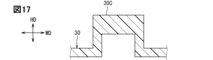
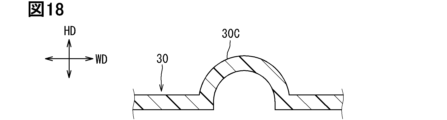
- the first recessed portion 33A, the second recessed portion 33B, the third recessed portion 34A, and the fourth recessed portion 32A may be collectively referred to as the recessed portion 30C.
- FIGS. 16 to 20 show another embodiment of the recessed portion 30C.
- the recessed portion 30C may be U-shaped at a substantially right angle.
- the thickness of the portion where the biasing portion 40 is formed in the recessed portion 30C may be locally thick.
- the recessed portion 30C may be U-shaped in a curved shape.
- the recessed portion 30C may be U-shaped with a substantially right-angled corner at one end and curved in a curved shape.
- the recessed portion 30C may be V-shaped.
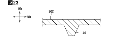
- FIGS. 21 to 26 show different embodiments of the biasing portion 40.
- the biasing portion 40 may have a rib shape extending in one direction.
- the biasing portion 40 may have a rib shape with a pointed tip. The pointed tip of the biasing portion 40 may be crushed as shown in FIG. 23 when pressed against the battery cell 20.
- the biasing portion 40 may have a rib shape extending in one direction while bending.
- the biasing portion 40 may have multiple rib shapes extending in one direction. As shown in FIG. 26, the multiple rib shapes may have different lengths.
- the battery cell includes electrode terminals (24, 25) and an electrode surface (20A) on which the electrode terminals are provided,
- the target wall is provided to face the electrode surface in a height direction (HD),
- a notch (36) is formed in the target wall to expose the electrode terminal;
- the target wall further includes a tunnel-shaped exhaust duct (50) extending away from the electrode surface and penetrating in the thickness direction to exhaust gas discharged from the battery cell, A battery module according to Technical Idea 3, wherein an end of the smoke exhaust duct is located farther from the electrode surface than the recess in the height direction.
- the frame has two pairs of the opposing walls, A first pair of opposing walls (33, 35) is provided at both ends of the main body wall in the height direction, A second pair of opposing walls (32, 34) is provided at both ends of the main body wall in the width direction (WD) of the battery cell, the first opposing wall includes a first side wall (33) that faces the electrode surface in the height direction as one of the target walls, a first target biasing portion (41, 42) that extends from the first side wall toward the electrode surface and biases the battery cell in a direction away from the first side wall in the height direction, and a second side wall (35) against which the battery cell is pressed by the first target biasing portion;
- the battery module described in any one of technical ideas 3 to 5, wherein the second opposing wall is another of the target walls and comprises a third side wall (34) that faces the side surface (20D) of the battery cell in the width direction, a second target biasing portion (43) that extends from the third side wall toward the battery cell and biases
- the first target biasing portion includes two first target biasing portions,
- the first side wall has an inner surface on which two first target biasing portions are provided, the two first target biasing portions being spaced apart from each other in the width direction.
- the second target biasing portion is provided,
- the second target biasing portion is provided on the inner surface of the third side wall,
- the frame is A plate-shaped main body wall (31) overlapping the battery cell in the thickness direction; a pair of opposing walls (32, 33, 34, 35) provided at both ends of the main body wall in a direction different from the thickness direction and extending in the thickness direction so as to face the battery cells; a biasing portion (41, 42, 43) provided on an inner surface (30A) of at least one of the pair of opposing walls and extending toward the battery cell to bias the battery cell, A battery stack, wherein one of the pair of opposing walls, the target wall on which the biasing portion is provided, has a recessed portion (32A, 33A, 33B, 34A
- the battery cell includes electrode terminals (24, 25) and an electrode surface (20A) on which the electrode terminals are provided,
- the target wall is provided to face the electrode surface in a height direction (HD)
- a notch (36) is formed in the target wall to expose the electrode terminal; the electrode terminal is exposed from the notch and extends farther from the electrode surface than the recessed portion; the recessed portion and the electrode terminal are spaced apart from each other in a width direction (WD) of the battery cell, the bus bar is connected to the electrode terminal in a state where the bus bar is fixed from the electrode surface side by the bus bar holding wall,
- the battery stack according to Technical Idea 9, wherein the bus bar holding wall and the recessed portion do not overlap with each other in the height direction.
Landscapes
- Chemical & Material Sciences (AREA)
- Chemical Kinetics & Catalysis (AREA)
- Electrochemistry (AREA)
- General Chemical & Material Sciences (AREA)
- Engineering & Computer Science (AREA)
- Aviation & Aerospace Engineering (AREA)
- Inorganic Chemistry (AREA)
- Manufacturing & Machinery (AREA)
- Battery Mounting, Suspending (AREA)
- Gas Exhaust Devices For Batteries (AREA)
- Connection Of Batteries Or Terminals (AREA)
Priority Applications (1)
| Application Number | Priority Date | Filing Date | Title |
|---|---|---|---|
| DE112023005096.1T DE112023005096T5 (de) | 2022-12-07 | 2023-11-15 | Batteriemodul und Batteriestapel |
Applications Claiming Priority (2)
| Application Number | Priority Date | Filing Date | Title |
|---|---|---|---|
| JP2022-195907 | 2022-12-07 | ||
| JP2022195907A JP7740219B2 (ja) | 2022-12-07 | 2022-12-07 | 電池モジュール、および、電池スタック |
Publications (1)
| Publication Number | Publication Date |
|---|---|
| WO2024122291A1 true WO2024122291A1 (ja) | 2024-06-13 |
Family
ID=91379121
Family Applications (1)
| Application Number | Title | Priority Date | Filing Date |
|---|---|---|---|
| PCT/JP2023/041107 Ceased WO2024122291A1 (ja) | 2022-12-07 | 2023-11-15 | 電池モジュール、および、電池スタック |
Country Status (3)
| Country | Link |
|---|---|
| JP (1) | JP7740219B2 (https=) |
| DE (1) | DE112023005096T5 (https=) |
| WO (1) | WO2024122291A1 (https=) |
Cited By (1)
| Publication number | Priority date | Publication date | Assignee | Title |
|---|---|---|---|---|
| EP4704231A1 (en) * | 2024-08-29 | 2026-03-04 | Prime Planet Energy & Solutions, Inc. | Battery assembly and battery pack |
Citations (5)
| Publication number | Priority date | Publication date | Assignee | Title |
|---|---|---|---|---|
| JP2012248482A (ja) * | 2011-05-30 | 2012-12-13 | Toshiba Corp | 二次電池装置 |
| JP2013242967A (ja) * | 2012-05-17 | 2013-12-05 | Denso Corp | 組電池 |
| JP2015201289A (ja) * | 2014-04-07 | 2015-11-12 | 株式会社Gsユアサ | 蓄電装置 |
| JP2018185924A (ja) * | 2017-04-25 | 2018-11-22 | 株式会社豊田自動織機 | 電池モジュール |
| JP2019145459A (ja) * | 2018-02-23 | 2019-08-29 | 株式会社東芝 | 組電池 |
-
2022
- 2022-12-07 JP JP2022195907A patent/JP7740219B2/ja active Active
-
2023
- 2023-11-15 WO PCT/JP2023/041107 patent/WO2024122291A1/ja not_active Ceased
- 2023-11-15 DE DE112023005096.1T patent/DE112023005096T5/de active Pending
Patent Citations (5)
| Publication number | Priority date | Publication date | Assignee | Title |
|---|---|---|---|---|
| JP2012248482A (ja) * | 2011-05-30 | 2012-12-13 | Toshiba Corp | 二次電池装置 |
| JP2013242967A (ja) * | 2012-05-17 | 2013-12-05 | Denso Corp | 組電池 |
| JP2015201289A (ja) * | 2014-04-07 | 2015-11-12 | 株式会社Gsユアサ | 蓄電装置 |
| JP2018185924A (ja) * | 2017-04-25 | 2018-11-22 | 株式会社豊田自動織機 | 電池モジュール |
| JP2019145459A (ja) * | 2018-02-23 | 2019-08-29 | 株式会社東芝 | 組電池 |
Cited By (1)
| Publication number | Priority date | Publication date | Assignee | Title |
|---|---|---|---|---|
| EP4704231A1 (en) * | 2024-08-29 | 2026-03-04 | Prime Planet Energy & Solutions, Inc. | Battery assembly and battery pack |
Also Published As
| Publication number | Publication date |
|---|---|
| JP2024082152A (ja) | 2024-06-19 |
| DE112023005096T5 (de) | 2025-10-23 |
| JP7740219B2 (ja) | 2025-09-17 |
Similar Documents
| Publication | Publication Date | Title |
|---|---|---|
| JP7852633B2 (ja) | 蓄電装置 | |
| JP7484178B2 (ja) | 蓄電装置 | |
| JP2019021593A (ja) | 電線配索構造及びバスバモジュール | |
| CN103703586A (zh) | 汇流条壳体、蓄电装置和车辆 | |
| JP7194337B2 (ja) | 密閉型電池 | |
| US11600889B2 (en) | Energy storage device | |
| JP7605204B2 (ja) | 蓄電設備 | |
| WO2024122291A1 (ja) | 電池モジュール、および、電池スタック | |
| JP7589444B2 (ja) | 蓄電装置 | |
| US10938014B2 (en) | Battery wiring module | |
| WO2023223961A1 (ja) | 蓄電装置 | |
| JP2019102258A (ja) | 蓄電素子 | |
| JP7725827B2 (ja) | 蓄電装置 | |
| WO2023013466A1 (ja) | 蓄電装置 | |
| WO2021187114A1 (ja) | 蓄電装置 | |
| WO2024185893A1 (ja) | 蓄電装置 | |
| JP7658065B2 (ja) | 蓄電装置 | |
| JP2024021469A (ja) | 蓄電装置 | |
| JP2023136719A (ja) | 蓄電装置 | |
| JP7753711B2 (ja) | 蓄電装置 | |
| JP7780413B2 (ja) | 電池モジュール | |
| JP7516809B2 (ja) | 蓄電装置 | |
| JP7528482B2 (ja) | 蓄電素子 | |
| WO2024101198A1 (ja) | 蓄電装置 | |
| WO2024101199A1 (ja) | 蓄電装置 |
Legal Events
| Date | Code | Title | Description |
|---|---|---|---|
| 121 | Ep: the epo has been informed by wipo that ep was designated in this application |
Ref document number: 23900412 Country of ref document: EP Kind code of ref document: A1 |
|
| WWE | Wipo information: entry into national phase |
Ref document number: 202517040802 Country of ref document: IN |
|
| WWP | Wipo information: published in national office |
Ref document number: 202517040802 Country of ref document: IN |
|
| WWE | Wipo information: entry into national phase |
Ref document number: 112023005096 Country of ref document: DE |
|
| WWP | Wipo information: published in national office |
Ref document number: 112023005096 Country of ref document: DE |
|
| 122 | Ep: pct application non-entry in european phase |
Ref document number: 23900412 Country of ref document: EP Kind code of ref document: A1 |