WO2024117110A1 - モータの故障検出装置及びモータの故障検出方法 - Google Patents
モータの故障検出装置及びモータの故障検出方法 Download PDFInfo
- Publication number
- WO2024117110A1 WO2024117110A1 PCT/JP2023/042482 JP2023042482W WO2024117110A1 WO 2024117110 A1 WO2024117110 A1 WO 2024117110A1 JP 2023042482 W JP2023042482 W JP 2023042482W WO 2024117110 A1 WO2024117110 A1 WO 2024117110A1
- Authority
- WO
- WIPO (PCT)
- Prior art keywords
- motor
- magnetic sensors
- misalignment
- detection unit
- fault
- Prior art date
- Legal status (The legal status is an assumption and is not a legal conclusion. Google has not performed a legal analysis and makes no representation as to the accuracy of the status listed.)
- Ceased
Links
Images






Classifications
-
- G—PHYSICS
- G01—MEASURING; TESTING
- G01B—MEASURING LENGTH, THICKNESS OR SIMILAR LINEAR DIMENSIONS; MEASURING ANGLES; MEASURING AREAS; MEASURING IRREGULARITIES OF SURFACES OR CONTOURS
- G01B7/00—Measuring arrangements characterised by the use of electric or magnetic techniques
-
- G—PHYSICS
- G01—MEASURING; TESTING
- G01R—MEASURING ELECTRIC VARIABLES; MEASURING MAGNETIC VARIABLES
- G01R31/00—Arrangements for testing electric properties; Arrangements for locating electric faults; Arrangements for electrical testing characterised by what is being tested not provided for elsewhere
-
- G—PHYSICS
- G01—MEASURING; TESTING
- G01R—MEASURING ELECTRIC VARIABLES; MEASURING MAGNETIC VARIABLES
- G01R31/00—Arrangements for testing electric properties; Arrangements for locating electric faults; Arrangements for electrical testing characterised by what is being tested not provided for elsewhere
- G01R31/34—Testing dynamo-electric machines
-
- G—PHYSICS
- G01—MEASURING; TESTING
- G01R—MEASURING ELECTRIC VARIABLES; MEASURING MAGNETIC VARIABLES
- G01R33/00—Arrangements or instruments for measuring magnetic variables
- G01R33/02—Measuring direction or magnitude of magnetic fields or magnetic flux
-
- H—ELECTRICITY
- H02—GENERATION; CONVERSION OR DISTRIBUTION OF ELECTRIC POWER
- H02K—DYNAMO-ELECTRIC MACHINES
- H02K11/00—Structural association of dynamo-electric machines with electric components or with devices for shielding, monitoring or protection
- H02K11/20—Structural association of dynamo-electric machines with electric components or with devices for shielding, monitoring or protection for measuring, monitoring, testing, protecting or switching
- H02K11/21—Devices for sensing speed or position, or actuated thereby
- H02K11/215—Magnetic effect devices, e.g. Hall-effect or magneto-resistive elements
Definitions
- This disclosure relates to a motor fault detection device and a motor fault detection method.
- a motor that has a sensor unit that includes a flat magnet attached to the rotating shaft and multiple magnetic sensors such as Hall elements that are arranged opposite the magnet and detect changes in the magnetic field caused by switching between the north and south poles of the magnet.
- the multiple magnetic sensors in this sensor unit are arranged at equal intervals on a circumference surrounding the rotating shaft, and each output a signal in response to changes in the magnetic field. The rotation speed, etc. can be calculated based on these signals.
- a first hall element group and a second hall element group are arranged in a sensor unit, and axis misalignment is detected based on the signals of the first hall element group and the second hall element group.
- This disclosure provides a technique that simplifies the detection of shaft misalignment in a brushless DC motor.
- a motor fault detection device includes an axis deviation detection unit that detects magnetism from a magnet that rotates with the motor's rotating shaft and detects an axis deviation, which is a deviation between the center of a circle passing through the multiple magnetic sensors and the rotating shaft, based on signals from the multiple magnetic sensors from a sensor unit including multiple magnetic sensors arranged along a circumference, and a fault detection unit that detects a fault in the motor based on the detected axis deviation.
- FIG. 1 is a diagram illustrating an example of the configuration of a motor module according to an embodiment.
- FIG. 2A is a diagram illustrating an example of the configuration of a motor according to an embodiment.
- FIG. 2B is a diagram illustrating an example of the configuration of a motor according to an embodiment.
- FIG. 3A is a diagram illustrating an example of the configuration of a sensor unit according to an embodiment.
- FIG. 3B is a diagram illustrating an example of the configuration of the sensor unit according to the embodiment.
- FIG. 4 is a diagram illustrating an example of the configuration of a failure detection device according to the embodiment.
- FIG. 5 is a diagram illustrating an example of a signal of the magnetic sensor according to the embodiment.
- FIG. 6A is a diagram illustrating an example of an arrangement of magnetic sensors and sector intervals according to the embodiment.
- FIG. 6B is a diagram illustrating an example of the arrangement of the magnetic sensors and the sector interval according to the embodiment.
- FIG. 7 is a diagram showing an example of a sector interval according to the embodiment.
- FIG. 8A is a diagram illustrating an example of detection of axis misalignment according to the first embodiment.
- FIG. 8B is a diagram illustrating another example of detection of axis misalignment according to the first embodiment.
- FIG. 9 is a diagram illustrating an example of a failure detection method according to the embodiment.
- FIG. 10A is a diagram showing an example of a sector interval according to the second embodiment.
- FIG. 10B is a diagram showing an example of a sector interval according to the second embodiment.
- Motor module 1 is a diagram showing an example of the configuration of a motor module according to an embodiment. As shown in the figure, a motor module 1 according to the embodiment includes a motor 2, an inverter circuit 3, and a control circuit 4.
- Motor 2 is a three-phase brushless DC motor. This motor 2 includes a stator 23, a rotor 22, and magnetic sensors 31 to 33.
- the rotor 22 is fixed to the rotating shaft 21 and rotates. Permanent magnets are arranged in this rotor 22.
- the rotor 22 in the figure shows a four-pole rotor.
- the stator 23 is disposed around the rotor 22 and generates a magnetic field to rotate the rotor 22.
- Three field coils 24 are disposed on the stator 23 at equal intervals in the circumferential direction.
- the magnetic sensors 31 to 33 detect the rotation angle (electrical angle) of the rotating shaft 21. These magnetic sensors 31 to 33 detect the rotation angle of the rotating shaft 21 by detecting changes in the magnetic field of the rotor 22, etc.
- a magnetic sensor using a Hall element, etc. can be used for the magnetic sensors 31, etc.
- the magnetic sensors 31, etc. can be arranged according to the number of phases of the motor 2.
- the inverter circuit 3 is a circuit that drives the motor 2. This inverter circuit 3 converts DC voltage to AC voltage and outputs the converted AC voltage to the motor 2.
- the inverter circuit 3 can be configured with a three-phase (U-phase, V-phase, and W-phase) bridge circuit.
- the inverter circuit 3 in the figure shows an example in which IGBTs (Insulated Gate Bipolar Transistors) are used as switching elements.
- the control circuit 4 controls the rotation of the motor 2. This control circuit 4 controls the rotation of the motor 2 by controlling the on/off state of the switch elements that make up the inverter circuit 3. The control circuit 4 outputs drive signals for the switch elements that make up the inverter circuit 3. The control circuit 4 also detects the rotation angle of the rotating shaft 21 based on signals from the magnetic sensor 31, etc., and generates drive signals for the above-mentioned switch elements.
- [Motor configuration] 2A and 2B are diagrams showing an example of the configuration of a motor according to an embodiment.
- the figures show an example of the configuration of a motor 2, and an example of the arrangement of a magnetic sensor 31 and the like. Note that the stator 23 is omitted in the figures.
- the sensor unit 30 in the figures is formed by a substrate on which the magnetic sensor 31 and the like are arranged.
- FIG. 2A shows an example in which the sensor unit 30 is disposed inside the housing 20.
- the magnetic sensor 31 and the like of the sensor unit 30 in the figure detect changes in the magnetic field of the rotor 22.
- FIG. 2B shows an example in which the sensor unit 30 is disposed outside the housing 20.
- the motor 2 in the figure is equipped with a sensor magnet 40.
- This sensor magnet 40 can be composed of a magnet fixed to the end of the rotating shaft 21.
- the sensor magnet 40 rotates together with the rotating shaft 21.
- the sensor unit 30 in the figure is disposed close to the sensor magnet 40.
- the magnetic sensor 31 etc. in the figure detect changes in the magnetic field of the sensor magnet 40.
- FIG. 3A is a diagram showing a configuration example of a sensor unit according to an embodiment.
- the figure shows a configuration example of a sensor unit 30.
- the figure shows a rotor 22 and a rotating shaft 21 in a schematic manner.
- the rotor 22 in the figure is assumed to have two poles.
- the two-dot chain line of the rotor 22 in the figure indicates the boundary between the magnetic poles.
- the description will be given assuming a two-pole rotor 22.
- the motor fault detection device according to the present disclosure can also be applied to a multi-pole rotor 22.
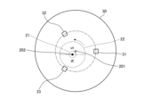
- the sensor unit 30 in the figure includes magnetic sensors 31, 32, and 33.
- the magnetic sensors 31 to 33 are disposed equidistant from the center 202 of the rotating shaft 21 and are disposed along a circumference (indicated by a dashed line in the figure) surrounding the center 202 of the rotating shaft 21.
- the magnetic sensors 31 to 33 can also be disposed at equal intervals.
- the open circles in the figure represent the centers 201 of the magnetic sensors 31 to 33. This center 201 corresponds to the center of a circle that passes through the magnetic sensors 31 to 33. In a normal motor 2, the centers 201 of the magnetic sensors 31 etc. coincide with the center 202 of the rotating shaft 21.
- FIG. 3B is a diagram showing an example of the configuration of a sensor unit according to an embodiment.
- This figure shows an example in which the center 201 of the magnetic sensors 31 etc. does not coincide with the center 202 of the rotating shaft 21.
- a deviation occurs in the position of the center 201 of the magnetic sensors 31 etc. and the center 202 (black circle) of the rotating shaft 21.
- This deviation between the center 201 of the magnetic sensors 31 etc. and the center 202 of the rotating shaft 21 is called axial deviation.
- the motor failure detection device disclosed herein detects this axial deviation and detects a failure in the motor 2.
- FIG. 4 is a diagram showing a configuration example of a fault detection device according to an embodiment.
- the figure is a block diagram showing a configuration example of a fault detection device 100.
- the fault detection device 100 includes an axis deviation detection unit 110, a fault detection unit 120, and a communication unit 130. Note that the figure further shows a sensor unit 30 in which magnetic sensors 31 to 33 are arranged.
- the shaft misalignment detection unit 110 detects shaft misalignment based on the signals from the magnetic sensors 31 to 33. This shaft misalignment detection unit 110 outputs the detected shaft misalignment to the fault detection unit 120. Details of shaft misalignment detection will be described later.
- the fault detection unit 120 detects faults in the motor 2 based on the shaft misalignment detected by the shaft misalignment detection unit 110. This fault detection unit 120 outputs the detection result to the communication unit 130. Details of fault detection will be described later.
- the communication unit 130 transmits the results of the detection of a fault in the motor 2 to an external device.
- the communication unit 130 can transmit information on whether or not the motor 2 is faulty.
- FIG. 5 is a diagram showing an example of a signal of a magnetic sensor according to the embodiment.
- the figure shows an example of a signal of a magnetic sensor.
- the magnetic sensor 31 etc. outputs a binarized signal according to a magnetic field.
- the part of this signal with a value of 1 represents the north pole, and the part with a value of 0 represents the south pole.
- Magnetic sensor 31", “magnetic sensor 32" and “magnetic sensor 33” in the figure show the waveforms of the signals of the magnetic sensors 31, 32 and 33, respectively.
- the rotation angle of the rotating shaft 21 can be divided into 60° electrical angles. These divided sections are called sectors.
- “Sector” in the figure shows a number that identifies the sector.
- Rotation angle” in the figure shows the rotation angle of the rotating shaft 21 in electrical angle. ⁇ 0 to ⁇ 5 of this rotation angle show the angle of division of the sector.
- FIG. 6A is a diagram showing an example in which the center 201 of the magnetic sensor 31 etc. and the center 202 of the rotation shaft 21 coincide with each other.
- the sector interval is an electrical angle of 60°.
- the sector interval in the case in which the center 201 of the magnetic sensor 31 etc. and the center 202 of the rotation shaft 21 coincide with each other is referred to as the reference sector interval.
- FIG. 6B shows an example in which the center 201 of the magnetic sensor 31 etc. and the center 202 of the rotation shaft 21 do not coincide, and shows a case in which an axial misalignment occurs. As shown in the figure, the axial misalignment causes variation in the sector spacing.
- the sector interval L i is calculated by ⁇ i - ⁇ i-1 .
- the upper diagram in the figure shows the sector interval when the center 201 of the magnetic sensor 31 etc. and the center 202 of the rotation shaft 21 coincide with each other.
- Each sector interval is an electrical angle of 60°.
- the lower diagram in the figure shows an example of the sector interval when an axis misalignment occurs. The axis misalignment can be detected by detecting the difference between this sector interval L i ' and the reference sector interval.
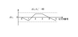
- FIG. 8A is a diagram showing an example of detection of an axis misalignment according to the first embodiment.
- the figure is a graph showing the difference ⁇ L i between the sector interval L i ' and the reference sector interval of 60° electrical angle.
- the vertical axis shows ⁇ L i
- the horizontal axis shows the sector number.
- the figure shows ⁇ L i calculated based on the sector interval in the lower diagram of FIG. 7.
- the axis misalignment detection unit 110 calculates the difference ⁇ L i in the figure based on the signals of the magnetic sensors 31 to 33, and detects this difference as the axis misalignment. When the axis misalignment is large, the malfunction becomes noticeable.
- the malfunction detection unit 120 can detect a malfunction of the motor 2 when the axis misalignment output from the axis misalignment detection unit 110 exceeds a predetermined threshold.
- the fault detection unit 120 can also detect a fault based on the number of differences ⁇ L i that exceed a threshold value.
- FIG. 8B is a diagram showing another example of detection of axis misalignment according to the first embodiment.
- the figure is a graph showing an integrated value ⁇ i of the difference ⁇ L i .
- the vertical axis shows the integrated value ⁇ i
- the horizontal axis shows the sector number.
- the figure shows an integrated value ⁇ i calculated based on the difference ⁇ L i in FIG. 8A.
- This integrated value ⁇ i indicates an angle deviation from the original ⁇ i.
- the axis misalignment detection unit 110 calculates the integrated value ⁇ i in the figure based on the signals of the magnetic sensors 31 to 33, and detects this integrated value as an axis misalignment.
- the failure detection unit 120 compares the integrated value with a predetermined threshold value to determine that the motor 2 in which the sensor unit 30 is arranged is faulty.
- the dashed line in the figure shows the threshold value.
- FIG. 9 is a diagram showing an example of a fault detection method according to the embodiment.
- the figure is a flow chart showing an example of a procedure of fault detection processing in the fault detection device 100.
- the fault detection device 100 is connected to the magnetic sensors 31 to 33 to acquire sensor signals (step S101).
- the axis deviation detection unit 110 detects the axis deviation based on the signals of the magnetic sensors 31 to 33 (step S102). This can be performed by calculating the difference ⁇ L i or the integrated value ⁇ i .
- the fault detection unit 120 detects a fault in the motor 2 based on the axis deviation (step S103).
- the above procedure allows the fault of the motor 2 to be detected.
- the fault can be detected in the manufacturing process of the motor 2.
- the fault can also be detected in the inspection process of the used motor 2.
- the fault detection device 100 disclosed herein can detect shaft misalignment based on the signals of the magnetic sensors 31 to 33, and can detect a fault in the motor 2 based on the detected shaft misalignment. This makes it easy to detect a fault in the motor 2.
- Second embodiment In the first embodiment described above, the axis shift is detected based on the difference in the sector intervals, whereas in the second embodiment of the present disclosure, the amount of axis shift is directly calculated from the sector intervals, which is different from the first embodiment.
- FIGS. 10A and 10B are diagrams showing an example of a sector interval according to the second embodiment.
- Fig. 10A shows the sector interval when the center 201 of the magnetic sensor 31 and the center 202 of the rotation shaft 21 coincide with each other.
- Fig. 10B shows the sector interval when an axis misalignment occurs.
- the distance between the sensor 31 and the center 201 is represented by r.
- the coordinates of the magnetic sensors 31 to 33 are also shown in the figure. In the figure, the position of the magnetic sensor 31 is assumed to be the reference position.
- the center 201 of the axially misaligned magnetic sensor 31 etc. can be expressed as (tx, ty).
- angle ⁇ a corresponds to ⁇ 0 ' and ⁇ 3 '
- angle ⁇ b corresponds to ⁇ 2 ' and ⁇ 5 '
- angle ⁇ c corresponds to ⁇ 1 ' and ⁇ 4 '.
- tx r ⁇ (1/2 ⁇ (( ⁇ 3)/(tan( ⁇ c ⁇ a) ⁇ tan( ⁇ b ⁇ a))))) (1)
- ty -r ⁇ (( ⁇ 3)/2) ⁇ (tan( ⁇ c ⁇ a)+tan( ⁇ b ⁇ a))/(tan( ⁇ c ⁇ a) ⁇ tan( ⁇ b ⁇ a)) ...
- the mechanical angles ⁇ a, ⁇ b, and ⁇ c of the magnetic sensors 31 etc. can be expressed as follows using the mechanical angle errors ⁇ a, ⁇ b, and ⁇ c.
- the mechanical angle errors ⁇ a, ⁇ b, and ⁇ c can be considered to be sufficiently small.
- the axis misalignment detection unit 110 of the second embodiment can calculate the axis misalignment based on any one of the above-mentioned formulas (1), (2), (3), and (4).
- the amount of axis misalignment can be calculated based on the following formula. ⁇ ((tx) 2 + (ty) 2 )
- the calculated amount of axis misalignment exceeds a threshold value set as an allowable amount of axis misalignment, it can be detected as an axis misalignment.
- the case where the motor 2 is a two-pole motor has been described so far, the case where the motor 2 is a multi-pole motor can also be considered in the same manner. If the number of pole pairs is N, the sector divisions exist from ⁇ 0 to ⁇ 6N-1 .
- the mechanical angles ⁇ a, ⁇ b, and ⁇ c can be expressed as follows, for example, using one detection angle.
- the configuration of the fault detection device 100 is the same as that of the fault detection device 100 of the first embodiment, so a description thereof will be omitted.
- the fault detection device 100 of the second embodiment of the present disclosure can directly calculate and detect the amount of axis misalignment from the sector interval. By detecting a fault in the motor 2 based on the detected axis misalignment, it is possible to easily detect a fault in the motor 2.
- each device described in this specification may be realized using software, hardware, or a combination of software and hardware.
- the programs constituting the software are stored in advance, for example, in a storage medium (non-transitory media) provided inside or outside each device. Then, each program is loaded into RAM, for example, when executed by a computer, and executed by a processor such as a CPU.
- the motor fault detection device 100 includes an axis misalignment detection unit 110 and a fault detection unit 120.
- the axis misalignment detection unit 110 detects magnetism from a magnet rotating together with the rotating shaft of the motor 2, and detects axis misalignment, which is a deviation between the center of a circle passing through the plurality of magnetic sensors and the rotating shaft, based on signals from the plurality of magnetic sensors from a sensor unit 30 including a plurality of magnetic sensors 31 to 33 arranged along a circumference.
- the fault detection unit 120 detects a fault in the motor 2 based on the detected axis misalignment. This makes it possible to detect axis misalignment from the signals from the magnetic sensors 31 to 33, making it easy to detect axis misalignment.
Landscapes
- Physics & Mathematics (AREA)
- General Physics & Mathematics (AREA)
- Engineering & Computer Science (AREA)
- Microelectronics & Electronic Packaging (AREA)
- Power Engineering (AREA)
- Condensed Matter Physics & Semiconductors (AREA)
Priority Applications (1)
| Application Number | Priority Date | Filing Date | Title |
|---|---|---|---|
| JP2024561496A JPWO2024117110A1 (https=) | 2022-11-30 | 2023-11-28 |
Applications Claiming Priority (2)
| Application Number | Priority Date | Filing Date | Title |
|---|---|---|---|
| JP2022191559 | 2022-11-30 | ||
| JP2022-191559 | 2022-11-30 |
Publications (1)
| Publication Number | Publication Date |
|---|---|
| WO2024117110A1 true WO2024117110A1 (ja) | 2024-06-06 |
Family
ID=91323796
Family Applications (1)
| Application Number | Title | Priority Date | Filing Date |
|---|---|---|---|
| PCT/JP2023/042482 Ceased WO2024117110A1 (ja) | 2022-11-30 | 2023-11-28 | モータの故障検出装置及びモータの故障検出方法 |
Country Status (2)
| Country | Link |
|---|---|
| JP (1) | JPWO2024117110A1 (https=) |
| WO (1) | WO2024117110A1 (https=) |
Cited By (2)
| Publication number | Priority date | Publication date | Assignee | Title |
|---|---|---|---|---|
| CN119469055A (zh) * | 2024-11-12 | 2025-02-18 | 浙江大学 | 一种磁悬浮泵转子空间姿态的检测方法和装置 |
| CN120008458A (zh) * | 2025-04-22 | 2025-05-16 | 吉林大学 | 一种识别转子偏心故障的自供电检测传感器及方法 |
Citations (6)
| Publication number | Priority date | Publication date | Assignee | Title |
|---|---|---|---|---|
| JPH01316511A (ja) * | 1988-06-16 | 1989-12-21 | Hitachi Ltd | 立軸回転電機の偏心監視装置 |
| JPH0421384A (ja) * | 1990-05-14 | 1992-01-24 | Yamaha Corp | モータ組み込み型ロータリエンコーダ |
| JP2005283165A (ja) * | 2004-03-26 | 2005-10-13 | Minebea Co Ltd | バリアブルリラクタンスレゾルバとそれを用いた回転角度センサ |
| WO2021059838A1 (ja) * | 2019-09-27 | 2021-04-01 | 日本電産株式会社 | 回転電機および診断装置 |
| KR102266447B1 (ko) * | 2019-12-30 | 2021-06-16 | 고려대학교 산학협력단 | 전동기, 전동기 고장 진단 장치 및 방법 |
| JP2022162813A (ja) * | 2021-04-13 | 2022-10-25 | 株式会社東芝 | 回転電機の異常検知装置および回転電機の異常検知方法 |
Family Cites Families (1)
| Publication number | Priority date | Publication date | Assignee | Title |
|---|---|---|---|---|
| CN103946673B (zh) * | 2011-11-24 | 2016-08-24 | 丰田自动车株式会社 | 旋转角检测装置以及具有旋转角检测装置的电动动力转向装置 |
-
2023
- 2023-11-28 JP JP2024561496A patent/JPWO2024117110A1/ja active Pending
- 2023-11-28 WO PCT/JP2023/042482 patent/WO2024117110A1/ja not_active Ceased
Patent Citations (6)
| Publication number | Priority date | Publication date | Assignee | Title |
|---|---|---|---|---|
| JPH01316511A (ja) * | 1988-06-16 | 1989-12-21 | Hitachi Ltd | 立軸回転電機の偏心監視装置 |
| JPH0421384A (ja) * | 1990-05-14 | 1992-01-24 | Yamaha Corp | モータ組み込み型ロータリエンコーダ |
| JP2005283165A (ja) * | 2004-03-26 | 2005-10-13 | Minebea Co Ltd | バリアブルリラクタンスレゾルバとそれを用いた回転角度センサ |
| WO2021059838A1 (ja) * | 2019-09-27 | 2021-04-01 | 日本電産株式会社 | 回転電機および診断装置 |
| KR102266447B1 (ko) * | 2019-12-30 | 2021-06-16 | 고려대학교 산학협력단 | 전동기, 전동기 고장 진단 장치 및 방법 |
| JP2022162813A (ja) * | 2021-04-13 | 2022-10-25 | 株式会社東芝 | 回転電機の異常検知装置および回転電機の異常検知方法 |
Cited By (2)
| Publication number | Priority date | Publication date | Assignee | Title |
|---|---|---|---|---|
| CN119469055A (zh) * | 2024-11-12 | 2025-02-18 | 浙江大学 | 一种磁悬浮泵转子空间姿态的检测方法和装置 |
| CN120008458A (zh) * | 2025-04-22 | 2025-05-16 | 吉林大学 | 一种识别转子偏心故障的自供电检测传感器及方法 |
Also Published As
| Publication number | Publication date |
|---|---|
| JPWO2024117110A1 (https=) | 2024-06-06 |
Similar Documents
| Publication | Publication Date | Title |
|---|---|---|
| WO2024117110A1 (ja) | モータの故障検出装置及びモータの故障検出方法 | |
| JP3909474B2 (ja) | 回転位置検出器および回転位置検出器付きモータ | |
| US9431939B2 (en) | Electric motor or generator | |
| US11228263B2 (en) | Motor control apparatus and motor control apparatus control method | |
| JP2003009500A (ja) | 3相環状コイル式永久磁石型回転電機 | |
| CN109905058B (zh) | 电机控制方法 | |
| JP2013504990A (ja) | 電気機械の作動のための方法および駆動装置 | |
| WO2013044440A1 (zh) | 一种伺服电机和伺服控制系统 | |
| JP6186824B2 (ja) | ブラシレスモータの制御装置、ブラシレスモータの電気角推定方法、および記憶媒体 | |
| JP2020502984A (ja) | 相転流におけるホール効果センサ信号オフセット補正 | |
| WO2020031942A1 (ja) | 位置推定方法、モータ制御装置およびモータシステム | |
| EP3340445B1 (en) | Electric motor | |
| WO2025110405A1 (ko) | 모터의 센서-리스 제어기동시간 저감을 위한 베이스섹터 각도 조정 방법 및 그 장치 | |
| JP7291104B2 (ja) | 3相ブラシレスモーター及び3相ブラシレスモーターの回転位置検出方法 | |
| JPWO2017195435A1 (ja) | モータモジュール、モータステップ動作制御システム、およびモータ制御装置 | |
| JP4926492B2 (ja) | モータ制御装置 | |
| JP6406114B2 (ja) | ブラシレスモータ | |
| US10812004B2 (en) | Motor system including reluctance motor | |
| JP3933108B2 (ja) | 電動駆動制御装置、電動駆動制御方法及びそのプログラム | |
| JP4027721B2 (ja) | ブラシレスモータの速度制御装置 | |
| CN112544034B (zh) | 位置推断方法、马达控制装置以及马达系统 | |
| US11050326B2 (en) | Reluctance motor and motor system including reluctance motor | |
| WO2020031943A1 (ja) | 位置推定方法、モータ制御装置およびモータシステム | |
| JP6619382B2 (ja) | モータ駆動制御装置及びモータ駆動制御装置の制御方法 | |
| WO2020031937A1 (ja) | 位置推定方法、モータ制御装置およびモータシステム |
Legal Events
| Date | Code | Title | Description |
|---|---|---|---|
| 121 | Ep: the epo has been informed by wipo that ep was designated in this application |
Ref document number: 23897758 Country of ref document: EP Kind code of ref document: A1 |
|
| WWE | Wipo information: entry into national phase |
Ref document number: 2024561496 Country of ref document: JP |
|
| NENP | Non-entry into the national phase |
Ref country code: DE |
|
| 122 | Ep: pct application non-entry in european phase |
Ref document number: 23897758 Country of ref document: EP Kind code of ref document: A1 |