WO2024116963A1 - ガスタービンの運転方法 - Google Patents
ガスタービンの運転方法 Download PDFInfo
- Publication number
- WO2024116963A1 WO2024116963A1 PCT/JP2023/041777 JP2023041777W WO2024116963A1 WO 2024116963 A1 WO2024116963 A1 WO 2024116963A1 JP 2023041777 W JP2023041777 W JP 2023041777W WO 2024116963 A1 WO2024116963 A1 WO 2024116963A1
- Authority
- WO
- WIPO (PCT)
- Prior art keywords
- hydrogen
- mixing ratio
- hydrogen mixing
- ratio
- fuel
- Prior art date
- Legal status (The legal status is an assumption and is not a legal conclusion. Google has not performed a legal analysis and makes no representation as to the accuracy of the status listed.)
- Ceased
Links
Images






Classifications
-
- F—MECHANICAL ENGINEERING; LIGHTING; HEATING; WEAPONS; BLASTING
- F02—COMBUSTION ENGINES; HOT-GAS OR COMBUSTION-PRODUCT ENGINE PLANTS
- F02C—GAS-TURBINE PLANTS; AIR INTAKES FOR JET-PROPULSION PLANTS; CONTROLLING FUEL SUPPLY IN AIR-BREATHING JET-PROPULSION PLANTS
- F02C3/00—Gas-turbine plants characterised by the use of combustion products as the working fluid
- F02C3/20—Gas-turbine plants characterised by the use of combustion products as the working fluid using a special fuel, oxidant, or dilution fluid to generate the combustion products
- F02C3/22—Gas-turbine plants characterised by the use of combustion products as the working fluid using a special fuel, oxidant, or dilution fluid to generate the combustion products the fuel or oxidant being gaseous at standard temperature and pressure
-
- F—MECHANICAL ENGINEERING; LIGHTING; HEATING; WEAPONS; BLASTING
- F02—COMBUSTION ENGINES; HOT-GAS OR COMBUSTION-PRODUCT ENGINE PLANTS
- F02C—GAS-TURBINE PLANTS; AIR INTAKES FOR JET-PROPULSION PLANTS; CONTROLLING FUEL SUPPLY IN AIR-BREATHING JET-PROPULSION PLANTS
- F02C7/00—Features, components parts, details or accessories, not provided for in, or of interest apart form groups F02C1/00 - F02C6/00; Air intakes for jet-propulsion plants
- F02C7/22—Fuel supply systems
-
- F—MECHANICAL ENGINEERING; LIGHTING; HEATING; WEAPONS; BLASTING
- F02—COMBUSTION ENGINES; HOT-GAS OR COMBUSTION-PRODUCT ENGINE PLANTS
- F02C—GAS-TURBINE PLANTS; AIR INTAKES FOR JET-PROPULSION PLANTS; CONTROLLING FUEL SUPPLY IN AIR-BREATHING JET-PROPULSION PLANTS
- F02C9/00—Controlling gas-turbine plants; Controlling fuel supply in air- breathing jet-propulsion plants
- F02C9/26—Control of fuel supply
- F02C9/40—Control of fuel supply specially adapted to the use of a special fuel or a plurality of fuels
-
- F—MECHANICAL ENGINEERING; LIGHTING; HEATING; WEAPONS; BLASTING
- F05—INDEXING SCHEMES RELATING TO ENGINES OR PUMPS IN VARIOUS SUBCLASSES OF CLASSES F01-F04
- F05D—INDEXING SCHEME FOR ASPECTS RELATING TO NON-POSITIVE-DISPLACEMENT MACHINES OR ENGINES, GAS-TURBINES OR JET-PROPULSION PLANTS
- F05D2220/00—Application
- F05D2220/30—Application in turbines
- F05D2220/32—Application in turbines in gas turbines
Definitions
- the present disclosure relates to a method of operating a gas turbine.
- This application claims priority based on Japanese Patent Application No. 2022-192566, filed with the Japan Patent Office on December 1, 2022, the contents of which are incorporated herein by reference.
- At least one embodiment of the present disclosure aims to increase the hydrogen co-firing rate while suppressing flame backflow, etc., during gas turbine operation.
- a method of operating a gas turbine comprising: A method for operating a gas turbine having a combustor that has a main nozzle and a pilot nozzle and can use hydrogen and a fuel other than hydrogen as fuel, comprising the steps of: The ratio of the hydrogen mixing ratio of the fuel injected from the pilot nozzle to the hydrogen mixing ratio of the fuel injected from the main nozzle is a second ratio during high hydrogen mixing ratio operation in which the hydrogen mixing ratio is higher than that during low hydrogen mixing ratio operation, which is larger than a first ratio during low hydrogen mixing ratio operation.
- FIG. 1 is a schematic diagram illustrating a gas turbine according to some embodiments.
- 1 is a cross-sectional view of a combustor according to some embodiments.
- 1 is a cross-sectional view illustrating a main portion of a combustor according to some embodiments.
- 2 is a diagram illustrating an arrangement of fuel injectors in a combustor according to some embodiments, viewed from the downstream side to the upstream side along an axial direction of the combustor;
- FIG. FIG. 2 is a schematic diagram of a fuel supply system for a combustor according to some embodiments.
- 1 is a graph showing an example of the relationship between the hydrogen mixing ratio of each combustion burner and the hydrogen mixing ratio of the entire combustor during rated operation.
- FIG. 1 is a graph showing an example of the relationship between the hydrogen mixing ratio of each combustion burner and the hydrogen mixing ratio of the entire combustor during rated operation.
- FIG. 1 is a graph showing an example of the relationship between the
- FIG. 6B is a graph showing an example of the relationship between the ratio of the hydrogen mixing ratio in the pilot combustion burner to the hydrogen mixing ratio in the main combustion burner and the hydrogen mixing ratio in the entire combustor, when the hydrogen mixing ratios of each combustion burner and the hydrogen mixing ratio in the entire combustor have the relationship shown in FIG. 6A .
- 13 is a graph showing another example of the relationship between the hydrogen mixing ratio of each combustion burner and the hydrogen mixing ratio of the entire combustor during rated operation.
- FIG. 7B is a graph showing an example of the relationship between the ratio of the hydrogen mixing ratio in the pilot combustion burner to the hydrogen mixing ratio in the main combustion burner and the hydrogen mixing ratio in the entire combustor, when the hydrogen mixing ratios of each combustion burner and the hydrogen mixing ratio in the entire combustor have the relationship shown in FIG. 7A .
- 13 is a graph showing yet another example of the relationship between the hydrogen mixing ratio of each combustion burner and the hydrogen mixing ratio of the entire combustor during rated operation.
- FIG. 8B is a graph showing an example of the relationship between the ratio of the hydrogen mixing ratio in the pilot combustion burner to the hydrogen mixing ratio in the main combustion burner and the hydrogen mixing ratio in the entire combustor, when the hydrogen mixing ratios of each combustion burner and the hydrogen mixing ratio in the entire combustor have the relationship shown in FIG. 8A .
- 1 is a graph showing an example of the relationship between the hydrogen mixing ratio of each combustion burner and the hydrogen mixing ratio of the entire combustor during partial load operation.
- 9B is a graph showing an example of the relationship between the ratio of the hydrogen mixing ratio in the pilot combustion burner to the hydrogen mixing ratio in the main combustion burner and the hydrogen mixing ratio in the entire combustor, when the hydrogen mixing ratios of each combustion burner and the hydrogen mixing ratio in the entire combustor have the relationship shown in FIG. 9A .
- expressions indicating that things are in an equal state such as “identical,””equal,” and “homogeneous,” not only indicate a state of strict equality, but also indicate a state in which there is a tolerance or a difference to the extent that the same function is obtained.
- expressions describing shapes such as a rectangular shape or a cylindrical shape do not only refer to rectangular shapes, cylindrical shapes, etc. in the strict geometric sense, but also refer to shapes that include uneven portions, chamfered portions, etc., to the extent that the same effect is obtained.
- the expressions “comprise,””include,””have,””includes,” or “have” of one element are not exclusive expressions excluding the presence of other elements.
- FIG. 1 is a schematic configuration diagram showing a gas turbine 1 according to some embodiments.
- a gas turbine which is an example of an application of a gas turbine operation method according to some embodiments, will be described with reference to FIG.
- a gas turbine 1 operated by a gas turbine operating method includes a compressor 2 for generating compressed air as an oxidant, a gas turbine combustor 4 for generating combustion gas using the compressed air and fuel, and a turbine 6 configured to be rotationally driven by the combustion gas.
- a generator (not shown) is connected to the turbine 6, and power is generated by the rotational energy of the turbine 6.
- the gas turbine combustor 4 is also simply referred to as the combustor 4.
- a compressor 2 includes a compressor casing 10, an air intake 12 provided on the inlet side of the compressor casing 10 for taking in air, a rotor 8 provided to penetrate both the compressor casing 10 and a turbine casing 22 described later, and various blades arranged in the compressor casing 10.
- the various blades include an inlet guide vane 14 provided on the air intake 12 side, a plurality of stator vanes 16 fixed on the compressor casing 10 side, and a plurality of rotor blades 18 planted on the rotor 8 so as to be arranged alternately with respect to the stator vanes 16.
- the compressor 2 may include other components such as an unillustrated bleed chamber.
- air taken in from the air intake 12 is compressed by passing through the plurality of stator vanes 16 and the plurality of rotor blades 18 to become high-temperature, high-pressure compressed air.
- the high-temperature, high-pressure compressed air is then sent from the compressor 2 to a downstream combustor 4.
- the combustor 4 is disposed within the casing 20. As shown in FIG. 1, a plurality of combustors 4 may be disposed within the casing 20 in an annular shape centered around the rotor 8. The combustor 4 is supplied with fuel and compressed air generated by the compressor 2, and the fuel is combusted to generate combustion gas, which is the working fluid of the turbine 6. The combustion gas is then sent from the combustor 4 to the downstream turbine 6.
- An example configuration of the combustor 4 according to some embodiments will be described later.
- the turbine 6 includes a turbine casing 22 and various blades arranged in the turbine casing 22.
- the various blades include a plurality of stator vanes 24 fixed to the turbine casing 22 side and a plurality of moving blades 26 implanted in the rotor 8 so as to be arranged alternately with respect to the stator vanes 24.
- the turbine 6 may include other components such as outlet guide vanes.
- the rotor 8 is driven to rotate by the combustion gas passing through the plurality of stator vanes 24 and the plurality of moving blades 26. This drives a generator connected to the rotor 8.
- An exhaust chamber 30 is connected to the downstream side of the turbine casing 22 via an exhaust casing 28. The combustion gas after driving the turbine 6 is exhausted to the outside via the exhaust casing 28 and the exhaust chamber 30.
- FIG. 2 is a cross-sectional view showing the combustor 4 according to some embodiments.
- Fig. 3 is a cross-sectional view showing a main part of the combustor 4 according to some embodiments.
- Fig. 4 is a diagram showing a schematic arrangement of each fuel injector when the combustor 4 according to some embodiments is viewed from the downstream side to the upstream side along the axial direction of the combustor 4. 2, 3 and 4, configurations of the combustor 4 according to some embodiments will be described.
- each combustor 4 includes a combustor liner 46 provided in a combustor chamber 40 defined by a casing 20, and a main combustion burner 60 and a pilot combustion burner 50, which are fuel injectors respectively arranged within the combustor liner 46.
- the combustor 4 further includes an outer casing 45 provided on the outer circumferential side of an inner casing 47 of the combustor liner 46 inside the casing 20.
- An air passage 43 through which compressed air flows is formed on the outer circumferential side of the inner casing 47 and on the inner circumferential side of the outer casing 45.
- the combustor 4 may include other components such as a bypass pipe (not shown) for bypassing the combustion gas.
- the combustor liner 46 has an inner cylinder 47 disposed around the pilot combustion burner 50 and the multiple main combustion burners 60, and a transition piece 48 connected to the tip of the inner cylinder 47. That is, the combustor liner 46 corresponds to a combustion section in which the fuel F injected from the main combustion burner 60 and the pilot combustion burner 50 is combusted. 3 and 4, the pilot combustion burner 50 is disposed along the central axis of the combustor liner 46. A plurality of main combustion burners 60 are disposed spaced apart from each other and aligned in the circumferential direction so as to surround the outer periphery of the pilot combustion burner 50.
- the pilot combustion burner 50 has a pilot nozzle 54 connected to a fuel port 52, a pilot burner cylinder 56 arranged to surround the pilot nozzle 54, and a plurality of swirlers (swirl plates) 58 provided on the outer periphery of the pilot nozzle 54.
- the pilot nozzle 54 extends in an axial direction Da about the combustor axis Ac.
- the upstream side in the direction of the axial direction Da which is the direction in which the combustor axis Ac extends, is defined as the upstream side
- the downstream side in the direction of the combustion gas flow is defined as the downstream side.
- the combustor axis Ac is also the burner axis of the pilot combustion burner 50.
- the downstream end of the pilot nozzle 54 is formed with an injection hole (not shown) for injecting fuel F.
- a plurality of swivel plates 58 are provided upstream of the position where the injection hole is formed in the pilot nozzle 54. Each swivel plate 58 is for swirling the compressed air around the combustor axis Ac. Each swivel plate 58 extends in a direction including a radial component from the outer periphery of the pilot nozzle 54 and is close to the inner periphery of the pilot burner tube 56.
- the pilot burner tube 56 has a main body portion 56a located on the outer periphery of the pilot nozzle 54 and a cone portion 56b connected to the downstream side of the main body portion 56a and gradually expanding in diameter toward the downstream side.
- the plurality of swivel plates 58 are close to the inner periphery of the main body portion 56a in the pilot burner tube 56.
- the pilot nozzle 54 has a water flow path (not shown) for suppressing the flame temperature to suppress NOx and the metal temperature of the cone portion 56b, and is configured to be able to inject water.
- the main combustion burner 60 has a main nozzle 64 connected to a fuel port 62, a main burner tube 66 arranged to surround the main nozzle 64, an extension tube 65 connecting the main burner tube 66 to the combustor liner 46 (e.g., the inner tube 47), and a swirler (swirl plate) 70 provided on the outer periphery of the main nozzle 64.
- a swirler swirl plate
- the main nozzle 64 is a rod-shaped nozzle extending in the axial direction Da centered on the burner axis Ab, which is parallel to the combustor axis Ac. Since the burner axis Ab of the main combustion burner 60 is parallel to the combustor axis Ac, the axial direction Da relative to the combustor axis Ac and the axial direction Da relative to the burner axis Ab are in the same direction. Furthermore, the upstream side of the axial direction Da relative to the combustor axis Ac is the upstream side of the axial direction Da relative to the burner axis Ab, and the downstream side of the axial direction Da relative to the combustor axis Ac is the downstream side of the axial direction Da relative to the burner axis Ab.
- Injection holes for injecting fuel F are formed in the middle of the main nozzle 64 in the axial direction Da.
- a number of swivel plates 70 are provided near the positions where the injection holes are formed in the main nozzle 64.
- Each swivel plate 70 is for swirling the compressed air around the burner axis Ab.
- Each swivel plate 70 extends from the outer periphery of the main nozzle 64 in a direction that includes a radial component, and is close to the inner circumferential surface of the main burner cylinder 66.
- the main burner cylinder 66 is located on the outer periphery of the main nozzle 64.
- the compressed air generated by the compressor 2 is supplied from the casing inlet 40a into the combustor casing 40, and then flows from the combustor casing 40 through the air passage 43 into the pilot burner tube 56 and the multiple main burner tubes 66.
- pilot combustion burner 50 fuel F injected from a pilot nozzle 54 is ejected together with compressed air from the downstream end of a pilot burner tube 56. This fuel F undergoes diffusion combustion or premixed combustion in the combustor liner 46. That is, the pilot fired burner 50 shown in Figures 2, 3 and 4 is a diffusion or premixed firing type fuel injector.
- the main combustion burner 60 In the main combustion burner 60, compressed air and fuel F injected from the main nozzle 64 are mixed in a main burner cylinder 66 to form a premixed gas PM. In the main combustion burner 60, the premixed gas PM is injected from the downstream end of the extension tube 65. The fuel F in this premixed gas PM is premixed and combusted in the combustor liner 46. That is, the main combustion burner 60 shown in Figures 2, 3 and 4 is a premixed combustion type fuel injector.
- an injection hole for injecting fuel F may be formed in the swivel plate 70, and fuel F may be injected from here into the main burner tube 66.
- the part corresponding to the rod-shaped main nozzle 64 described above forms a hub rod, and the main nozzle is formed by having this hub rod and multiple swivel plates 70. Fuel F is supplied from the outside into the hub rod, and fuel F is supplied from this hub rod to the swivel plates 70.
- the combustor 4 is configured to be able to use, for example, natural gas as in a conventional combustor, and also to use hydrogen as the fuel F.
- natural gas as the fuel F will be referred to as natural gas fuel FN, or simply as natural gas.
- hydrogen as the fuel F will be referred to as hydrogen fuel FH, or simply as hydrogen.
- natural gas fuel FN, hydrogen fuel FH, and mixed fuel FM of natural gas fuel FN and hydrogen fuel FH will be referred to as fuel F when there is no need to particularly distinguish between them or when these fuels are referred to collectively.
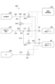
- Fig. 5 is a diagram showing an outline of a supply system 200 of fuel F to the combustor 4 according to some embodiments.
- the gas turbine 1 includes the supply system 200 of fuel F shown in Fig. 5.
- the supply system 200 of fuel F shown in Fig. 5 includes a first supply line 211 for supplying natural gas fuel FN to the main combustion burner 60, a second supply line 212 for supplying natural gas fuel FN to the pilot combustion burner 50, a third supply line 221 for supplying hydrogen fuel FH to the main combustion burner 60 and the pilot combustion burner 50, and a fourth supply line 222 for supplying hydrogen fuel FH to the pilot combustion burner 50.
- the natural gas fuel FN is supplied from a supply source 201 of the natural gas fuel FN via a natural gas supply line 210.
- the first supply line 211 and the second supply line 212 branch off at a branch point 231.
- the first supply line 211 is provided with a first adjustment valve 241 for adjusting the amount of fuel F supplied to the main combustion burner 60.
- the downstream end of the first supply line 211 is connected to a fuel port 62 to which a main nozzle 64 of the main combustion burner 60 is connected.
- the second supply line 212 is provided with a second control valve 242 for adjusting the amount of fuel F supplied to the pilot combustion burner 50.
- the downstream end of the second supply line 212 is connected to a fuel port 52 to which a pilot nozzle 54 of the pilot combustion burner 50 is connected.
- the hydrogen fuel FH is supplied from a supply source 202 of the hydrogen fuel FH via a hydrogen supply line 220.
- the third supply line 221 and the fourth supply line 222 branch off at a branch point 232.
- the third supply line 221 is provided with a third adjustment valve 243 for adjusting the supply amount of hydrogen fuel FH to the main combustion burner 60 and the pilot combustion burner 50.
- the downstream end of the third supply line 221 is connected to the natural gas supply line 210 at a junction 233 upstream of a branching portion 231 in the natural gas supply line 210. That is, the third adjustment valve 243 is an adjustment valve for adjusting the amount of hydrogen fuel FH added to the natural gas fuel FN flowing through the natural gas supply line 210 .
- the fourth supply line 222 is provided with a fourth adjustment valve 244 for adjusting the amount of hydrogen fuel FH supplied to the pilot combustion burner 50.
- the downstream end of the fourth supply line 222 is connected to the second supply line 212 at a junction 234 downstream of the second adjustment valve 242 in the second supply line 212.
- the fourth control valve 244 is a control valve that can adjust the amount of hydrogen fuel FH added to the natural gas fuel FN or the mixed fuel FM of the natural gas fuel FN and the hydrogen fuel FH flowing through the second supply line 212.
- the second control valve 242 and opening the fourth control valve 244 only the hydrogen fuel FH can be supplied to the pilot combustion burner 50.
- the opening degrees of the first control valve 241, the second control valve 242, the third control valve 243, and the fourth control valve 244 can be adjusted to adjust the hydrogen mixing ratio (calorie ratio), which is the ratio of hydrogen fuel FH in the fuel F injected in the main combustion burner 60 and the pilot combustion burner 50.
- the hydrogen mixing ratio calorie ratio
- the first control valve 241, the second control valve 242, the third control valve 243, and the fourth control valve 244 are controlled by a controller configured to be able to control each of these control valves.
- the controller is realized by the combustion control device 140 of the gas turbine 1.
- Each processing function of the combustion control device 140 is configured as software (computer program) and executed by a computer, but is not limited to this and may be configured as hardware.
- the gas turbine 1 includes a water supply line 215 for supplying cooling water to the pilot combustion burner 50. Although detailed description will be omitted, supplying cooling water suppresses the flame temperature that increases when the hydrogen mixing ratio in the pilot combustion burner 50 is increased, thereby suppressing the generation of NOx and suppressing the metal temperature of the cone portion 56b of the pilot combustion burner 50. Cooling water may be supplied to the pilot-fired burner 50 from a water source 205 via a water supply line 215 .
- the water supply line 215 is provided with a water supply amount adjustment valve 251 for adjusting the amount of water supplied to the pilot combustion burner 50. Although a detailed description will be omitted, the water supply amount adjustment valve 251 is controlled by the combustion control device 140.
- the main combustion burner 60 is a premixed combustion type fuel injector and the pilot combustion burner 50 is a diffusion or premixed combustion type fuel injector.
- a diffusion combustion type fuel injector has a lower risk of flashback than a premixed combustion type fuel injector, and therefore, in the embodiment shown in Figures 2, 3 and 4, the pilot combustion burner 50 is a fuel injector with a lower risk of flashback than the main combustion burner 60.
- a fuel injector when a fuel injector is surrounded by other fuel injectors, the surrounded fuel injector has a lower risk of flashback than a surrounding fuel injector. 2, 3 and 4, a plurality of main combustion burners 60 are arranged around the pilot combustion burner 50. Therefore, if the main combustion burner 60 and the pilot combustion burner 50 have the same fuel injector structure, as in the case where both the main combustion burner 60 and the pilot combustion burner 50 are diffusion combustion type or premixed combustion type fuel injectors in the embodiments shown in Fig. 2, 3 and 4, the pilot combustion burner 50 becomes a fuel injector with a smaller risk of flashback than the main combustion burner 60.
- the gas turbine 1 is operated as follows, taking these factors into consideration.
- the upper limit Crpmax of the hydrogen mixing ratio Crp in the pilot combustion burner 50 is set to be larger than the upper limit Crmmax of the hydrogen mixing ratio Crm in the main combustion burner 60. This makes it possible to increase the maximum value Cromax of the hydrogen mixing ratio Cro in the entire combustor 4 while suppressing flashback.
- the hydrogen co-firing ratio is controlled as follows.
- the hydrogen mixing ratio Cro in the entire combustor 4 is the ratio of the total hydrogen fuel FH to the total fuel F injected from the multiple main combustion burners 60 and the pilot combustion burner 50 in one combustor, expressed in terms of a calorie ratio.
- FIG. 6A is a graph showing an example of the relationship between the hydrogen mixing ratios Crm, Crp of each combustion burner and the hydrogen mixing ratio Cro of the entire combustor 4 during rated operation.
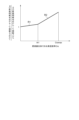
- FIG. 6B is a graph showing an example of the relationship between the ratio (Crp/Crm) of the hydrogen mixing ratio Crp in the pilot combustion burner 50 to the hydrogen mixing ratio Crm in the main combustion burner 60 and the hydrogen mixing ratio Cro in the entire combustor 4, when the hydrogen mixing ratios Crm, Crp of each combustion burner and the hydrogen mixing ratio Cro in the entire combustor 4 have the relationship shown in FIG. 6A.
- FIG. 6A is a graph showing an example of the relationship between the hydrogen mixing ratios Crm, Crp of each combustion burner and the hydrogen mixing ratio Cro of the entire combustor 4 during rated operation.
- FIG. 6B is a graph showing an example of the relationship between the ratio (Crp/Crm) of the hydrogen mixing ratio Crp in the pilot combustion burner 50 to the hydrogen mixing ratio Crm in
- FIG. 7A is a graph showing another example of the relationship between the hydrogen mixing ratios Crm, Crp of the combustion burners and the hydrogen mixing ratio Cro of the entire combustor 4 during rated operation.
- FIG. 7B is a graph showing an example of the relationship between the ratio (Crp/Crm) of the hydrogen mixing ratio Crp in the pilot combustion burner 50 to the hydrogen mixing ratio Crm in the main combustion burner 60 and the hydrogen mixing ratio Cro in the entire combustor 4, when the hydrogen mixing ratios Crm, Crp of each combustion burner and the hydrogen mixing ratio Cro in the entire combustor 4 have the relationship shown in FIG. 7A.
- FIG. 7A is a graph showing another example of the relationship between the hydrogen mixing ratios Crm, Crp of the combustion burners and the hydrogen mixing ratio Cro of the entire combustor 4 during rated operation.
- FIG. 7B is a graph showing an example of the relationship between the ratio (Crp/Crm) of the hydrogen mixing ratio Crp in the pilot combustion burner 50 to the hydrogen mixing ratio Cr
- FIG. 8A is a graph showing yet another example of the relationship between the hydrogen mixing ratios Crm, Crp of the combustion burners and the hydrogen mixing ratio Cro of the entire combustor 4 during rated operation.
- FIG. 8B is a graph showing an example of the relationship between the ratio (Crp/Crm) of the hydrogen mixing ratio Crp in the pilot combustion burner 50 to the hydrogen mixing ratio Crm in the main combustion burner 60 and the hydrogen mixing ratio Cro in the entire combustor 4, when the hydrogen mixing ratios Crm, Crp of each combustion burner and the hydrogen mixing ratio Cro in the entire combustor 4 have the relationship shown in FIG. 8A.
- FIG. 8A is a graph showing yet another example of the relationship between the hydrogen mixing ratios Crm, Crp of the combustion burners and the hydrogen mixing ratio Cro of the entire combustor 4 during rated operation.
- FIG. 8B is a graph showing an example of the relationship between the ratio (Crp/Crm) of the hydrogen mixing ratio Crp in the pilot combustion burner 50 to the hydrogen mixing
- FIG. 9A is a graph showing an example of the relationship between the hydrogen mixing ratios Crm, Crp of each combustion burner and the hydrogen mixing ratio Cro of the entire combustor 4 during partial load operation.
- FIG. 9B is a graph showing an example of the relationship between the ratio (Crp/Crm) of the hydrogen mixing ratio Crp in the pilot combustion burner 50 to the hydrogen mixing ratio Crm in the main combustion burner 60 and the hydrogen mixing ratio Cro in the entire combustor 4, when the hydrogen mixing ratios Crm, Crp of each combustion burner and the hydrogen mixing ratio Cro in the entire combustor 4 have the relationship shown in FIG. 9A.
- the hydrogen mixing ratios Crm, Crp of each combustion burner may be gradually increased while maintaining the same value as the hydrogen mixing ratio Cro of the entire combustor 4 increases.
- Such changes in the hydrogen mixing ratios Crm, Crp of each combustion burner can be achieved, for example, by gradually opening the third adjustment valve 243, which adjusts the amount of hydrogen fuel FH supplied to the main combustion burner 60 and the pilot combustion burner 50, while keeping the fourth adjustment valve 244, which adjusts the amount of hydrogen fuel FH supplied to the pilot combustion burner 50 shown in Figure 5, closed.
- the combustion control device 140 may send a control signal to the third control valve 243 so that the third control valve 243 operates in this manner.
- the hydrogen combustion ratio Crp of the pilot combustion burner 50 may be gradually increased to increase the hydrogen combustion ratio Cro of the entire combustor 4.
- the hydrogen combustion ratio Crp of the pilot combustion burner 50 may be gradually increased to increase the hydrogen combustion ratio Cro of the entire combustor 4.
- Such a transition of the hydrogen mixing ratios Crm, Crp of each combustion burner can be achieved, for example, by gradually closing the second control valve 242 of the second supply line 212 and gradually opening the fourth control valve 244 while keeping the opening degree of the third control valve 243 shown in FIG. 5 fixed. Additionally, the combustion control device 140 may send control signals to the second and fourth control valves 242, 244 to cause them to operate in this manner.
- the upper limit Crpmax of the hydrogen mixing ratio Crp in the pilot combustion burner 50 may be 100% as shown in FIG. 6A and in FIGS. 7A, 8A, and 9A described below.
- the hydrogen combustion ratio Cro in the entire combustor 4 is at the value th1 or the value th3 described below.
- the hydrogen combustion ratio Cro is equal to or less than the value th1 or the value th3, this is called low hydrogen combustion ratio operation, and when the hydrogen combustion ratio Cro exceeds the value th1 or the value th3, this is called high hydrogen combustion ratio operation.
- the above ratio (Crp/Crm) during low hydrogen fuel ratio operation is referred to as the first ratio R1
- the above ratio (Crp/Crm) during high hydrogen fuel ratio operation is referred to as the second ratio R2.
- the fourth control valve 244 for adjusting the supply amount of hydrogen fuel FH to the pilot combustion burner 50 is kept closed until the hydrogen mixing ratio Crm in the main combustion burner 60 reaches the upper limit value Crmmax.
- the fourth control valve 244 may start to be opened before the hydrogen mixing ratio Crm in the main combustion burner 60 reaches the upper limit value Crmmax.
- 7A and 7B is an example of a case where, in the process of increasing the hydrogen mixing ratio Cro in the entire combustor 4, the fourth control valve 244 starts to be opened when the hydrogen mixing ratio Crm in the main combustion burner 60 reaches a value th2 which is smaller than the value th1 (th2 ⁇ th1).
- the hydrogen mixing ratio Crp in the pilot combustion burner 50 is greater than the hydrogen mixing ratio Crm in the main combustion burner 60 until the hydrogen mixing ratio Cro in the entire combustor 4 reaches a value th1, and the difference between the two gradually increases as the hydrogen mixing ratio Cro in the entire combustor 4 increases.
- the hydrogen mixing ratio Crm in the main combustion burner 60 becomes the upper limit value Crmmax, and the hydrogen mixing ratio Crp in the pilot combustion burner 50 gradually increases. That is, in the example shown in FIG. 7A, in the process of increasing the hydrogen mixing ratio Cro in the entire combustor 4, after the hydrogen mixing ratio Cro in the entire combustor 4 reaches the value th1, for example, while keeping the opening of the third control valve 243 shown in FIG. 5 fixed, the second control valve 242 of the second supply line 212 may be gradually closed and the fourth control valve 244 may be gradually opened.
- the fourth control valve 244 for adjusting the supply amount of hydrogen fuel FH to the pilot combustion burner 50 is kept closed until the hydrogen mixing ratio Cro in the entire combustor 4 reaches the value th2.
- the fourth control valve 244 may be started to be opened at the same time as the third control valve 243 is started to be opened.
- the example shown in Figures 8A and 8B is an example of a case where the third control valve 243 and the fourth control valve 244 are started to be opened at the same time in the process of increasing the hydrogen mixing ratio Cro in the entire combustor 4.
- the hydrogen combustion ratio Crp in the pilot combustion burner 50 is greater than the hydrogen combustion ratio Crm in the main combustion burner 60 until the hydrogen combustion ratio Cro in the entire combustor 4 reaches a value th1, and the difference between the two gradually increases as the hydrogen combustion ratio Cro in the entire combustor 4 increases.
- the upper limit value Crpmax of the hydrogen mixing ratio Crp in the pilot combustion burner 50 is 100% during rated operation as shown in FIGS. 6A, 7A, and 8A, so there is no room to increase the upper limit value Crpmax of the hydrogen mixing ratio Crp in the pilot combustion burner 50.
- the upper limit value Crmmax of the hydrogen mixing ratio Crm in the main combustion burner 60 during partial load operation is made larger than that during rated operation, so that the maximum value Cromax of the hydrogen mixing ratio Cro in the entire combustor 4 during partial load operation is made larger than that during rated operation.
- the upper limit Crmmax of the hydrogen mixing ratio Crm in the main combustion burner 60 during partial load operation is made larger than that during rated operation.
- the hydrogen mixing ratios Crm, Crp of each combustion burner may be set to gradually increase while maintaining the same value as the hydrogen mixing ratio Cro of the entire combustor 4 increases.
- the hydrogen mixing ratio Crp of the pilot combustion burner 50 may be gradually increased to increase the hydrogen mixing ratio Cro of the entire combustor 4. That is, during high hydrogen mixing ratio operation in which the hydrogen mixing ratio is higher than during low hydrogen mixing ratio operation, the hydrogen mixing ratio Crp of the pilot combustion burner 50 may be gradually increased to increase the hydrogen mixing ratio Cro of the entire combustor 4. In the example shown in FIG.
- the second control valve 242 in the second supply line 212 may be gradually closed and the fourth control valve 244 may be gradually opened.
- the hydrogen mixing ratios Crm, Crp of each combustion burner when the hydrogen mixing ratios Crm, Crp of each combustion burner are changed, as shown in FIG. 9B , when the value of the hydrogen mixing ratio Cro is equal to or less than the value th3 (during low hydrogen mixing ratio operation), the ratio (Crp/Crm) of the hydrogen mixing ratio Crp in the pilot combustion burner 50 to the hydrogen mixing ratio Crm in the main combustion burner 60 becomes 1.
- the hydrogen mixing ratios Crm, Crp of each combustion burner are changed, as shown in FIG. 9B, when the hydrogen mixing ratio Cro exceeds the value th3 (during high hydrogen mixing ratio operation), the ratio (Crp/Crm) exceeds 1 and gradually increases as the hydrogen mixing ratio Cro increases.
- the upper limit value Crmmax of the hydrogen mixing ratio Crm in the main combustion burner 60 may be set to be larger as the combustion gas temperature T1T at the inlet of the gas turbine becomes lower.
- a method for operating a gas turbine is a method for operating a gas turbine 1 including a combustor 4 having a main nozzle 64 and a pilot nozzle 54, and capable of using hydrogen and a fuel other than hydrogen as fuel.
- the ratio (Crp/Crm) of the hydrogen combustion ratio Crp of the fuel F injected from the pilot nozzle 54 to the hydrogen combustion ratio Crm of the fuel F injected from the main nozzle 64 is larger in a second ratio R2 during high hydrogen combustion ratio operation in which the hydrogen combustion ratio Cro in the entire combustor 4 is higher than in low hydrogen combustion ratio operation, compared to a first ratio R1 during low hydrogen combustion ratio operation.
- the risk of backfire can be reduced by making the hydrogen mixing ratio Crp of the fuel F injected from the pilot combustion burner 50 higher than the hydrogen mixing ratio Crm of the fuel F injected from the main combustion burner 60.
- the gas turbine when the pilot combustion burner 50 is less likely to cause flashback than the main combustion burner 60, the gas turbine can be operated at a high hydrogen mixing ratio Cro while suppressing flashback.
- the second ratio R2 may be increased as the hydrogen mixing ratio of the fuel F supplied to the combustor 4 (the hydrogen mixing ratio Cro in the entire combustor 4) increases.
- the hydrogen mixing ratio Crm of the main combustion burner 60 is suppressed to suppress flashback, while the hydrogen mixing ratio Crp of the pilot combustion burner 50 is increased, thereby making it possible to increase the hydrogen mixing ratio Cro of the entire combustor 4.
- the hydrogen mixing ratio Crp of the fuel F injected from the pilot combustion burner 50 increases as the hydrogen mixing ratio of the fuel F supplied to the combustor 4 (the hydrogen mixing ratio Cro in the entire combustor 4) increases.
- the hydrogen mixing ratio Crp of the pilot combustion burner 50 by increasing the hydrogen mixing ratio Crp of the pilot combustion burner 50, it is possible to increase the hydrogen mixing ratio Cro in the entire combustor 4 while suppressing flashback.
- the rate of increase in the hydrogen mixing ratio Crp of the fuel F injected from the pilot combustion burner 50 relative to the rate of increase in the hydrogen mixing ratio of the fuel F supplied to the combustor 4 may be greater than the rate of increase in the hydrogen mixing ratio Crm of the fuel F injected from the main combustion burner 60 relative to the rate of increase in the hydrogen mixing ratio of the fuel F supplied to the combustor 4 (the hydrogen mixing ratio Cro in the entire combustor 4).
- the hydrogen mixing ratio Crm of the fuel F injected from the main combustion burner 60 may be a constant value regardless of the hydrogen mixing ratio of the fuel F supplied to the combustor 4 (the hydrogen mixing ratio Cro in the entire combustor 4).
- the hydrogen mixing ratio Crm of the main combustion burner 60 is kept constant to suppress flashback, while the hydrogen mixing ratio Crp of the pilot combustion burner 50 is increased, making it possible to increase the hydrogen mixing ratio Cro of the entire combustor 4.
- the upper limit value Crpmax of the hydrogen mixing ratio Crp of the fuel F injected from the pilot combustion burner 50 may be 100%.
- the hydrogen mixing ratio Crp of the pilot combustion burner 50 can be set to 100% while suppressing flashback in the combustor 4, and the hydrogen mixing ratio Cor in the entire combustor 4 can be increased.
- the first ratio R1 may be 1 during at least a portion of the low hydrogen co-firing ratio operation.
- the hydrogen mixing ratio Crm of the fuel F injected from the main combustion burner 60 and the hydrogen mixing ratio Crp of the fuel F injected from the pilot combustion burner 50 are equal, so that the supply system 200 for the fuel F to the main combustion burner 60 and the pilot combustion burner 50 can be shared as shown in FIG. 5, and therefore the supply system 200 for the fuel F can be simplified.
- the upper limit Crmmax of the hydrogen mixing ratio Crm of the fuel F injected from the main combustion burner 60 is preferably greater during partial load operation of the gas turbine 1 than during rated operation.
- the maximum value Cromax of the hydrogen mixing ratio Cro in the entire combustor 4 during partial load operation can be made larger than that during rated operation.
- the upper limit Crmmax of the hydrogen mixing ratio Crm of the main combustion burner 60 during partial load operation can be made larger than that during rated operation, so that the maximum value Cromax of the total hydrogen mixing ratio (hydrogen mixing ratio Cro in the entire combustor 4) during partial load operation can be made larger than that during rated operation.
- the hydrogen mixing ratio Cro in the entire combustor 4 can be increased.
- the combustor 4 may include a main combustion burner 60 having a main nozzle 64 and a pilot combustion burner 50 having a pilot nozzle 54.
- the main combustion burner 60 may be a premixed combustion type burner
- the pilot combustion burner 50 may be a diffusion combustion type burner.
- the pilot combustion burner 50 may have a water flow path and be configured to inject water. This makes it possible to suppress the flame temperature, thereby suppressing NOx and the metal temperature of the pilot combustion burner 50 (cone portion 56b).
- the present disclosure is not limited to the above-described embodiments, and includes modifications to the above-described embodiments and appropriate combinations of these modifications.
- the ratio (Crp/Crm) of the hydrogen mixing ratio Crp in the pilot combustion burner 50 to the hydrogen mixing ratio Crm in the main combustion burner 60 may be less than 1.
- a method of operating a gas turbine 1 is a method of operating a gas turbine 1 including a combustor 4 having a main nozzle 64 and a pilot nozzle 54, and capable of using hydrogen and a fuel other than hydrogen as fuel.
- a ratio (Crp/Crm) of the hydrogen mixing ratio (Crp) of the fuel F injected from the pilot nozzle 54 to the hydrogen mixing ratio (Crm) of the fuel F injected from the main nozzle 64 is greater in a second ratio R2 during high hydrogen mixing ratio operation in which the hydrogen mixing ratio (Cro) is higher than in low hydrogen mixing ratio operation, compared to a first ratio R1 during low hydrogen mixing ratio operation.
- the risk of flashback can be reduced by making the hydrogen mixing ratio (Crp) of the fuel F injected from the pilot nozzle 54 higher than the hydrogen mixing ratio (Crm) of the fuel F injected from the main nozzle 64.
- the pilot nozzle 54 is less likely to cause flame backflow than the main nozzle 64, it is possible to operate at a high hydrogen co-firing ratio (Cro) while suppressing backfire.
- the second ratio R2 may be increased as the hydrogen mixing ratio (Cro) of the fuel F supplied to the combustor 4 increases.
- the hydrogen combustion ratio (Crm) of the main nozzle 64 is suppressed to suppress flashback, while the hydrogen combustion ratio (Crp) of the pilot nozzle 54 is increased, thereby increasing the hydrogen combustion ratio Cro of the entire combustor 4.
- the hydrogen mixing ratio (Crp) of the fuel F injected from the pilot nozzle 54 may be increased as the hydrogen mixing ratio (Cro) of the fuel F supplied to the combustor 4 increases.
- the hydrogen combustion ratio (Crp) of the pilot nozzle 54 can be increased to suppress flashback while increasing the hydrogen combustion ratio Cro in the entire combustor 4.
- the rate of increase in the hydrogen mixing ratio (Crp) of the fuel F injected from the pilot nozzle 54 relative to the rate of increase in the hydrogen mixing ratio (Cro) of the fuel F supplied to the combustor 4 may be greater than the rate of increase in the hydrogen mixing ratio (Crm) of the fuel F injected from the main nozzle 64 relative to the rate of increase in the hydrogen mixing ratio (Cro) of the fuel F supplied to the combustor 4.
- the hydrogen combustion ratio (Crm) of the main nozzle 64 is suppressed to suppress flashback, while the hydrogen combustion ratio (Crp) of the pilot nozzle 54 is increased, thereby increasing the hydrogen combustion ratio Cro of the entire combustor 4.
- the hydrogen mixing ratio (Crm) of the fuel F injected from the main nozzle 64 may be a constant value regardless of the hydrogen mixing ratio (Cro) of the fuel F supplied to the combustor 4.
- the hydrogen combustion ratio (Crm) of the main nozzle 64 is kept constant to suppress flashback, while the hydrogen combustion ratio (Crp) of the pilot nozzle 54 is increased, thereby making it possible to increase the hydrogen combustion ratio Cro of the entire combustor 4.
- the upper limit of the hydrogen mixing ratio (Crp) of the fuel F injected from the pilot nozzle 54 may be 100%.
- the first ratio R1 may be 1 during at least a portion of the low hydrogen co-firing ratio operation.
- the hydrogen mixing ratio (Crm) of the fuel F injected from the main nozzle 64 is equal to the hydrogen mixing ratio (Crp) of the fuel F injected from the pilot nozzle 54, so the fuel F supply system 200 for the main nozzle 64 and the pilot nozzle 54 can be shared, and the fuel F supply system 200 can be simplified.
- the upper limit (Crmmax) of the hydrogen mixing ratio (Crm) of the fuel F injected from the main nozzle 64 may be greater during partial load operation of the gas turbine 1 than during rated operation.
- the risk of backfiring of the hydrogen fuel FH is smaller during partial load operation of the gas turbine 1 than during rated operation, so the maximum value Cromax of the hydrogen mixing ratio Cro in the entire combustor 4 during partial load operation can be made larger than during rated operation.
- the maximum value (Cromax) of the total hydrogen mixing ratio (Cro) during partial load operation can be made larger than during rated operation.
- the combustor 4 may include a main combustion burner 60 having a main nozzle 64 and a pilot combustion burner 50 having a pilot nozzle 54.
- the main combustion burner 60 may be a premixed combustion type burner
- the pilot combustion burner 50 may be a diffusion combustion type burner.
- the upper limit (Crpmax) of the hydrogen mixing ratio (Crp) of the pilot combustion burner 50 can be increased, and the total hydrogen mixing ratio (Cro) can be increased.
- the pilot nozzle 54 may have a water flow path and be configured to be able to inject water.
Landscapes
- Engineering & Computer Science (AREA)
- Chemical & Material Sciences (AREA)
- Combustion & Propulsion (AREA)
- Mechanical Engineering (AREA)
- General Engineering & Computer Science (AREA)
Priority Applications (4)
| Application Number | Priority Date | Filing Date | Title |
|---|---|---|---|
| DE112023004066.4T DE112023004066T5 (de) | 2022-12-01 | 2023-11-21 | Betriebsverfahren für gasturbine |
| JP2024561407A JP7780037B2 (ja) | 2022-12-01 | 2023-11-21 | ガスタービンの運転方法 |
| CN202380078560.6A CN120187942A (zh) | 2022-12-01 | 2023-11-21 | 燃气轮机的运行方法 |
| KR1020257016695A KR20250090344A (ko) | 2022-12-01 | 2023-11-21 | 가스 터빈의 운전 방법 |
Applications Claiming Priority (2)
| Application Number | Priority Date | Filing Date | Title |
|---|---|---|---|
| JP2022192566 | 2022-12-01 | ||
| JP2022-192566 | 2022-12-01 |
Publications (1)
| Publication Number | Publication Date |
|---|---|
| WO2024116963A1 true WO2024116963A1 (ja) | 2024-06-06 |
Family
ID=91323960
Family Applications (1)
| Application Number | Title | Priority Date | Filing Date |
|---|---|---|---|
| PCT/JP2023/041777 Ceased WO2024116963A1 (ja) | 2022-12-01 | 2023-11-21 | ガスタービンの運転方法 |
Country Status (5)
| Country | Link |
|---|---|
| JP (1) | JP7780037B2 (https=) |
| KR (1) | KR20250090344A (https=) |
| CN (1) | CN120187942A (https=) |
| DE (1) | DE112023004066T5 (https=) |
| WO (1) | WO2024116963A1 (https=) |
Citations (3)
| Publication number | Priority date | Publication date | Assignee | Title |
|---|---|---|---|---|
| JP2011075174A (ja) * | 2009-09-30 | 2011-04-14 | Hitachi Ltd | 水素含有燃料対応燃焼器および、その低NOx運転方法 |
| WO2022149540A1 (ja) * | 2021-01-08 | 2022-07-14 | 三菱重工業株式会社 | ガスタービン燃焼器及びガスタービン |
| WO2023140183A1 (ja) * | 2022-01-20 | 2023-07-27 | 三菱重工業株式会社 | ガスタービン燃焼器の制御方法及びガスタービン燃焼器の制御装置 |
Family Cites Families (2)
| Publication number | Priority date | Publication date | Assignee | Title |
|---|---|---|---|---|
| JP7149909B2 (ja) | 2019-09-17 | 2022-10-07 | 三菱重工業株式会社 | ガスタービン燃焼器 |
| US11306661B1 (en) | 2020-12-04 | 2022-04-19 | General Electric Company | Methods and apparatus to operate a gas turbine engine with hydrogen gas |
-
2023
- 2023-11-21 JP JP2024561407A patent/JP7780037B2/ja active Active
- 2023-11-21 CN CN202380078560.6A patent/CN120187942A/zh active Pending
- 2023-11-21 KR KR1020257016695A patent/KR20250090344A/ko active Pending
- 2023-11-21 WO PCT/JP2023/041777 patent/WO2024116963A1/ja not_active Ceased
- 2023-11-21 DE DE112023004066.4T patent/DE112023004066T5/de active Pending
Patent Citations (3)
| Publication number | Priority date | Publication date | Assignee | Title |
|---|---|---|---|---|
| JP2011075174A (ja) * | 2009-09-30 | 2011-04-14 | Hitachi Ltd | 水素含有燃料対応燃焼器および、その低NOx運転方法 |
| WO2022149540A1 (ja) * | 2021-01-08 | 2022-07-14 | 三菱重工業株式会社 | ガスタービン燃焼器及びガスタービン |
| WO2023140183A1 (ja) * | 2022-01-20 | 2023-07-27 | 三菱重工業株式会社 | ガスタービン燃焼器の制御方法及びガスタービン燃焼器の制御装置 |
Also Published As
| Publication number | Publication date |
|---|---|
| JPWO2024116963A1 (https=) | 2024-06-06 |
| DE112023004066T5 (de) | 2025-07-17 |
| JP7780037B2 (ja) | 2025-12-03 |
| CN120187942A (zh) | 2025-06-20 |
| KR20250090344A (ko) | 2025-06-19 |
Similar Documents
| Publication | Publication Date | Title |
|---|---|---|
| US7673454B2 (en) | Combustor of gas turbine and combustion control method for gas turbine | |
| US10865989B2 (en) | Combustor arrangement having arranged in an upstream to downstream flow sequence a radial swirler, pre-chamber with a convergent portion and a combustion chamber | |
| CN107110506B (zh) | 烧嘴、燃烧器以及燃气轮机 | |
| KR101792453B1 (ko) | 가스 터빈 연소기, 가스 터빈, 제어 장치 및 제어 방법 | |
| CN206113000U (zh) | 用于燃气涡轮发动机的燃烧器的燃料喷嘴 | |
| JP6626743B2 (ja) | 燃焼装置及びガスタービン | |
| CN110878948B (zh) | 燃气轮机轴向分级燃烧室及其控制方法 | |
| CN110220213A (zh) | 用于燃气涡轮发动机的燃料喷射器组件 | |
| JP2014132214A (ja) | 燃焼器に燃料を供給する燃料噴射器 | |
| JP2006336995A (ja) | ガスタービンの燃焼器 | |
| EP2943725A1 (en) | Lean-rich axial stage combustion in a can-annular gas turbine engine | |
| CN102809176A (zh) | 气动力燃料喷嘴 | |
| US20140352312A1 (en) | Injector for introducing a fuel-air mixture into a combustion chamber | |
| KR102322596B1 (ko) | 연소기용 노즐 어셈블리 및 이를 포함하는 가스터빈 연소기 | |
| RU2570480C2 (ru) | Способ смешивания разбавляющего воздуха в системе последовательного сгорания газовой турбины | |
| US9322336B2 (en) | Fuel nozzle for gas turbine | |
| US20170009994A1 (en) | Combustor | |
| CN115127123A (zh) | 径向分级燃烧室、燃气轮机发电系统和燃烧调控的方法 | |
| WO2022149540A1 (ja) | ガスタービン燃焼器及びガスタービン | |
| JP2023110852A (ja) | 燃焼器用ノズル、燃焼器およびこれを含むガスタービン | |
| CN115875693A (zh) | 燃气轮机头部一体化燃烧室和燃气轮机发电系统 | |
| CN115989383A (zh) | 用于燃气涡轮机的燃烧器 | |
| JP7780037B2 (ja) | ガスタービンの運転方法 | |
| JP7285623B2 (ja) | ガスタービン燃焼器及びそれを備えるガスタービン、並びに、ガスタービン燃焼器の燃焼振動抑制方法 | |
| JP7408908B2 (ja) | 燃焼器用ノズル、燃焼器およびこれを含むガスタービン |
Legal Events
| Date | Code | Title | Description |
|---|---|---|---|
| 121 | Ep: the epo has been informed by wipo that ep was designated in this application |
Ref document number: 23897611 Country of ref document: EP Kind code of ref document: A1 |
|
| WWE | Wipo information: entry into national phase |
Ref document number: 2024561407 Country of ref document: JP |
|
| WWE | Wipo information: entry into national phase |
Ref document number: 202380078560.6 Country of ref document: CN |
|
| ENP | Entry into the national phase |
Ref document number: 20257016695 Country of ref document: KR Kind code of ref document: A |
|
| WWE | Wipo information: entry into national phase |
Ref document number: 112023004066 Country of ref document: DE |
|
| WWP | Wipo information: published in national office |
Ref document number: 1020257016695 Country of ref document: KR |
|
| WWP | Wipo information: published in national office |
Ref document number: 202380078560.6 Country of ref document: CN |
|
| WWP | Wipo information: published in national office |
Ref document number: 112023004066 Country of ref document: DE |
|
| 122 | Ep: pct application non-entry in european phase |
Ref document number: 23897611 Country of ref document: EP Kind code of ref document: A1 |