WO2024116936A1 - 情報処理装置及び新生児の体重の推定方法 - Google Patents
情報処理装置及び新生児の体重の推定方法 Download PDFInfo
- Publication number
- WO2024116936A1 WO2024116936A1 PCT/JP2023/041637 JP2023041637W WO2024116936A1 WO 2024116936 A1 WO2024116936 A1 WO 2024116936A1 JP 2023041637 W JP2023041637 W JP 2023041637W WO 2024116936 A1 WO2024116936 A1 WO 2024116936A1
- Authority
- WO
- WIPO (PCT)
- Prior art keywords
- model
- image
- target
- subject
- head
- Prior art date
- Legal status (The legal status is an assumption and is not a legal conclusion. Google has not performed a legal analysis and makes no representation as to the accuracy of the status listed.)
- Ceased
Links
Images






Classifications
-
- A—HUMAN NECESSITIES
- A61—MEDICAL OR VETERINARY SCIENCE; HYGIENE
- A61B—DIAGNOSIS; SURGERY; IDENTIFICATION
- A61B5/00—Measuring for diagnostic purposes; Identification of persons
- A61B5/103—Measuring devices for testing the shape, pattern, colour, size or movement of the body or parts thereof, for diagnostic purposes
- A61B5/107—Measuring physical dimensions, e.g. size of the entire body or parts thereof
-
- G—PHYSICS
- G06—COMPUTING OR CALCULATING; COUNTING
- G06T—IMAGE DATA PROCESSING OR GENERATION, IN GENERAL
- G06T7/00—Image analysis
- G06T7/60—Analysis of geometric attributes
- G06T7/62—Analysis of geometric attributes of area, perimeter, diameter or volume
Definitions
- the present invention relates to an information processing device and a method for estimating the weight of a newborn baby.
- Patent Document 1 discloses a technology for measuring the heart rate of a newborn inside an incubator. For some newborns (particularly premature babies), the act of touching to obtain biometric information may be considered an invasive procedure. The technology of Patent Document 1 has the advantage that the heart rate can be measured without touching the newborn, thereby reducing the number of invasive procedures.
- Patent Document 1 depending on the type of biometric information, it is necessary to touch the newborn to measure it. For example, when measuring weight, it is necessary to touch the newborn.
- the present invention aims to make it possible to measure biometric information without touching the object, which in conventional technology requires touching the object to measure it.
- the information processing device of the present invention comprises an acquisition unit that acquires image information showing a three-dimensional image of an object lying on a flat surface captured from above, a recognition unit that recognizes an object image representing the object among the objects displayed in the three-dimensional image, and an estimation unit that uses the object image to estimate the shape of the object, including the missing lower part in the object image, assuming that the object is in contact with the flat surface at its bottom, and calculates the object's physical information using the estimated object shape.
- biometric information that previously required touching the subject to measure can now be measured without touching the subject.
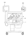
- FIG. 2 is a diagram for explaining each component of the information processing system.
- FIG. 2 is a diagram illustrating the hardware configuration of a computer.
- FIG. 2 is a functional block diagram of the information processing system.
- FIG. 11 is a diagram for explaining a specific example of a target image.
- FIG. 11 is another diagram for explaining a specific example of the target image.
- FIG. 2 is a diagram for explaining a configuration for generating an object model.
- FIG. 11 is a diagram for explaining head size approximation processing, etc.
- 11A and 11B are diagrams for explaining a head model deformation process.
- 11A and 11B are diagrams for explaining a torso model transformation process.
- FIG. 11 is a diagram for explaining a target model according to the second embodiment.
- 13A and 13B are diagrams for explaining ellipse app
- FIG. 1 is a diagram for explaining each component of the information processing system 1.
- the information processing system 1 of this embodiment includes a computer 100 and a depth camera 200. The above components are connected so that they can communicate with each other.
- an incubator is used as the computer 100.
- a mat is provided inside the incubator.
- a newborn baby hereinafter "subject S” lies on the upper surface of the mat (hereinafter "flat surface A").
- Flat surface A is a plane with an approximately rectangular outer edge.
- the depth camera 200 generates a three-dimensional image (distance image) that includes depth information indicating the distance to the subject.
- the three-dimensional image may be a point cloud image captured using LIDAR (Light Detection and Ranging, Laser Imaging Detection and Ranging) technology.
- LIDAR Light Detection and Ranging, Laser Imaging Detection and Ranging
- the weight or height of the subject S is estimated by the computer 100 by capturing an image of the subject S with the depth camera 200.
- image information Dg of a three-dimensional image showing the target S is transmitted to the computer 100.
- the computer 100 uses the image information Dg received from the depth camera 200 to generate a target model M showing the shape (size) of the photographed target S (see FIG. 6 described below).
- the volume of the target model M described above is estimated as the volume of the photographed target S, and the weight of the target S is estimated by multiplying the estimated result by the density.
- the height of the target model M is estimated as the height of the photographed target S.
- an incubator is used as the computer 100, but the computer 100 may be configured separately from the incubator.
- the depth camera 200 may also have the functions of the computer 100.
- the incubator may also be equipped with the depth camera 200.
- the image information Dg is transmitted from the depth camera 200 to the computer 100 via wireless communication
- the image information D may be transmitted via wired communication.
- FIG. 2 is a diagram showing the hardware configuration of this embodiment.
- the computer 100 includes a CPU (Central Processing Unit) 101, a ROM (Read Only Memory) 102, a RAM (Random access memory) 103, a monitor 104, a memory 105, and a communication unit 106.
- CPU Central Processing Unit
- ROM Read Only Memory
- RAM Random access memory
- the ROM 102 of the computer 100 stores various data including programs in a non-volatile manner.
- the CPU 101 executes the programs to realize various functions (such as the estimation unit 13) described below.
- the RAM 103 temporarily stores, for example, various information referenced by the CPU 101 when executing the programs.
- the monitor 104 displays various information. For example, the monitor 104 displays the biological information of the subject S in an incubator.
- the memory 105 stores various types of information in a non-volatile manner.
- a flash memory can be used as the memory 105.
- the memory 105 stores information necessary for estimating the weight and height of the target S. Specifically, information indicating a head model Mh, a torso model Mb, an arm model Ma, and a leg model Ml for generating a target model M described below is stored in the memory 105.
- the communication unit 106 receives various types of information from an external device. For example, image information Dg transmitted from the depth camera 200 is received by the communication unit 106.
- FIG. 3 is a functional block diagram of the information processing system 1 in this embodiment.
- the information processing system 1 includes an information processing device 10 and an image capturing device 20.
- the above-mentioned computer 100 functions as the information processing device 10 by executing a program
- the depth camera 200 functions as the image capturing device 20.
- image information Dg indicating the captured three-dimensional image G is transmitted from the image capturing device 20 to the information processing device 10.
- the information processing device 10 includes an acquisition unit 11, a recognition unit 12, an estimation unit 13, a memory unit 14, a calculation unit 15, and a measurement unit 16.
- the acquisition unit 11 acquires image information Dg indicating a three-dimensional image G obtained by photographing an object S lying on a flat surface A from above. Specifically, the acquisition unit 11 acquires the image information Dg from the photographing device 20.
- the three-dimensional image G obtained by photographing an object S lying on a flat surface A from above includes a flat image Ga representing the flat surface A in addition to an object image Gs representing the object S (see FIG. 5).
- the recognition unit 12 recognizes a target image Gs representing a target S among the objects displayed in the three-dimensional image. Specifically, the recognition unit 12 separately recognizes the target image Gs representing the target S and the flat image Ga representing the flat surface A.
- a technique for recognizing each object in the three-dimensional image G for example, a segmentation technique is preferably adopted. AI (Artificial Intelligence) technology may be adopted for the above segmentation.
- each object in the three-dimensional image G is segmented using a trained FCN (Fully Convolutional Network) (for example, the technology described in JP 2022-29169 A may be adopted).
- FCN Fast Convolutional Network
- the estimation unit 13 estimates the volume of the target S using the target image Gs. Let us assume that a target image Gs that represents the entire target S (both the upper and lower parts) has been captured. In this case, the volume of the target S approximately matches the volume of the target image Gs. Therefore, the volume of the target image Gs that represents the entire target S can be estimated as the volume of the target S.
- this embodiment employs a configuration that can estimate the volume of the target S with high accuracy even from a target image Gs in which the lower portion of the target S is missing.
- the estimation unit 13 of this embodiment assumes that the bottom side of the target S is in contact with the flat surface A, and estimates the volume of the target S, including the bottom portion missing in the target image Gs, using the target image Gs.
- the storage unit 14 stores model information indicating the shape of each model (such as head model Mh) representing each part (such as the head) of the target S (see FIG. 6 described below).
- the model information in this embodiment is image information indicating a head model Mh that is a model of the head of the target S, image information indicating a torso model Mb that is a model of the torso of the target S, image information indicating an arm model Ma that is a model of the arms of the target S, and image information indicating a leg model Ml that is a model of the legs of the target S.
- the estimation unit 13 uses the target image Gs to deform the shape of each model (Mh, Mb, Ma, Ml) so that the shape approximates the shape of the part of the target S to which the model corresponds.
- the estimation unit 13 also uses each model after deformation to generate a target model M that indicates the overall shape of the target S.
- the estimation unit 13 estimates the volume of the target model M as the volume of the target S.
- the estimation unit 13 deforms the shapes of the head model Mh and torso model Mb of the models, the estimation unit 13 deforms the shapes of the models assuming that the target S is in contact with the flat surface A on the underside. Specifically, the estimation unit 13 identifies a reference plane Fa that passes through the flat image Ga (see FIG. 5). The estimation unit 13 also deforms the models (Mh, Mb) based on the distance from the target image Gs to the reference plane Fa (Lhz in FIG. 8(b)) (see FIGS. 7(a)(b), 8(a)-(c), and 9(a)(b)), and estimates the volume of the target S using the deformed models. The above configuration will be described in detail later.
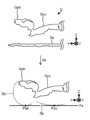
- FIG. 4 is a diagram for explaining a specific example of the configuration up to the generation of the target image Gs.
- a mat is provided inside the incubator so that the flat surface A is approximately parallel to the horizontal direction.
- the vertical direction may be referred to as the "z-axis direction” below.
- the longitudinal direction of the flat surface A may be referred to as the "x-axis direction” and the width direction of the flat surface A may be referred to as the "y-axis direction”.
- the x-y plane is approximately parallel to the horizontal direction. Note that in this embodiment, it is assumed that the target S lies on the flat surface A with the top of the head facing the x-axis direction, as shown in FIG. 4.
- a newborn baby lying on a flat surface A is photographed as a target S by the photographing device 20 (depth camera 200).
- the target S is photographed from above (in the direction of arrow d).
- the flat surface A is photographed in addition to the target S.
- image information Dg indicating the three-dimensional image G is transmitted to the information processing device 10 (Sa1 in Figure 4).
- the center of Figure 4 shows a simulated three-dimensional image G captured by the imaging device 20.
- the direction in the three-dimensional image space corresponding to the z-axis direction (vertical direction) may be referred to as the "Z-axis direction”.
- the direction corresponding to the x-axis direction may be referred to as the "X-axis direction”
- the direction corresponding to the y-axis direction may be referred to as the "Y-axis direction”.
- the three-dimensional image G indicated by the image information Dg includes a target image Gs and a flat image Ga.
- the target image Gs represents the target S
- the flat image Ga represents the flat surface A. Note that, for the sake of explanation, the target image Gs and the flat image Ga are shown in different colors in Figure 4 (the same applies to Figure 5 described below).
- the information processing device 10 recognizes each image of the three-dimensional image G, including the target image Gs and the flat image Ga, using segmentation technology (Sa2 in FIG. 4). For example, the target image Gs and the flat image Ga are recognized as images showing separate objects.
- the lower part of Figure 4 shows an excerpt of the target image Gs from the three-dimensional image G.
- the target image Gs includes a head image Gsh, a chest image Gsc, a waist image Gsw, an arm image Gsa, and a leg image Gsl.
- the head image Gsh represents the head of the target S.
- the chest image Gsc represents the chest of the torso of the target S from the neck to the navel
- the waist image Gsw represents the torso of the target S from the navel to the legs
- the arm image Gsa represents the arms of the target S
- the leg image Gsl represents the legs of the target S.
- Each of the above images is recognized as an image showing a separate object using segmentation techniques.
- FIG. 5 is a diagram for explaining the reference plane Fa.
- the reference plane Fa is a plane that passes through the flat surface A, and is used when estimating the volume of the target S.
- FIG. 5 shows a simulated diagram of a three-dimensional image G (target image Gs, flat image Ga). In the specific example of FIG. 5, it is assumed that the three-dimensional image G is viewed in the X-axis direction. Note that in FIG. 5, the head image Gsh and chest image Gsc are selected from the target image Gs and the other images (such as the arm image Gsa) are omitted.
- the specific example in FIG. 5 like the specific example in FIG. 4 described above, assumes that subject S lying on flat surface A is photographed from above.
- the subject image Gs includes an image showing the upper part of subject S, but does not include (is missing) the lower part of subject S.
- the specific example in FIG. 5 assumes that subject S (newborn baby) is lying on his back on flat surface A.
- the head image Gsh of subject image Gs represents the face side (eyes, nose, mouth) of subject S, but does not include the back side of subject S's head.
- the chest image Gsc of subject image Gs represents the abdominal side (chest, navel) of subject S, but does not include the back side of subject S.
- the information processing device 10 of this embodiment identifies a reference plane Fa from a flat image Ga (Sb in FIG. 5).
- the flat image Ga is a point cloud image.
- the reference plane Fa is calculated by plane approximation using the least squares method. That is, the plane that minimizes the sum of the squares of the distances from each point that constitutes the flat image Ga is identified as the reference plane Fa.
- Figure 5 shows a conceptual diagram of the reference plane Fa.
- the flat image Ga is perpendicular to the Z-axis direction (vertical direction). Therefore, the reference plane Fa is also perpendicular to the Z-axis direction.
- the flat image Ga is also parallel to the X-Y plane (horizontal direction). Therefore, the reference plane Fa is also parallel to the X-Y plane.
- the lower portion of the subject image Gs is missing.
- the lower portion (Sh, Sb) of the subject S missing from the subject image Gs is indicated by dashed lines.
- the back of the head Sh missing from the head image Gsh and the back Sb missing from the chest image Gsc of the subject image Gs are indicated by dashed lines.
- the lower end Pah of the back of the head Sh of subject S typically touches the flat surface A. That is, the lower end Pah of the back of the head Sh of subject S is missing from the target image Gs, but the point in the three-dimensional image space corresponding to the lower end Pah is located on the reference plane Fa.
- the lower end Pac of the back Sb of subject S typically touches the flat surface A. That is, the lower end Pac of the back Sb of subject S is missing from the target image Gs, but the point in the three-dimensional image space corresponding to the lower end Pac is located on the reference plane Fa.
- FIG. 6 is a diagram for explaining a specific example of each process for generating the target model M.
- the target model M represents the overall shape of the target S.
- the information processing device 10 generates the target model M from the captured target image Gs, and estimates the volume of the target model M as the volume of the target S.
- model information indicating a head model Mh, a torso model Mb, an arm model Ma, and a leg model Ml is stored in advance in the storage unit 14 of the information processing device 10.
- the torso model Mb is configured to include a chest model Mc and a waist model Mw.
- the head model Mh (before deformation) stored in the memory unit 14 represents the average shape of the head of the subject S.
- the torso model Mb stored in the memory unit 14 represents the average shape of the torso of the subject S
- the waist model Mw stored in the memory unit 14 represents the average shape of the waist of the subject S
- the arm model Ma stored in the memory unit 14 represents the average shape of the arms of the subject S
- the leg model Ml stored in the memory unit 14 represents the average shape of the legs of the subject S.
- the information processing device 10 When the information processing device 10 acquires a target image Gs from the photographing device 20, it extracts a head image Gsh from the target image Gs. The information processing device 10 then executes a head size approximation process (S1 in FIG. 6) using the head image Gs and the head model Mh. In the head size approximation process, the rough shape (size) of the head model Mh is determined (see FIG. 7(a) described below). After executing the head size approximation process, the information processing device 10 then executes a head model rotation process (S2 in FIG. 6). In the head model rotation process, the orientation of the head model Mh is rotated (adjusted) in accordance with the orientation of the head image Gh (see FIG. 7(b)).
- the information processing device 10 executes a head model deformation process (S3 in FIG. 6).
- the shape of the head model Mh is deformed so as to approximate the shape of the head of the target S (to the size of the head of the target S) assuming that the target S is in contact with the flat surface A on the underside (see FIGS. 8(a) to (c) described later).
- the information processing device 10 executes a torso image rotation process (S4 in FIG. 7).
- the torso image rotation process the orientation of the torso model Mb and the orientation of the torso image Gb are aligned.
- the torso model Mb is oriented in the X-axis direction beforehand.
- the torso image rotation process the torso image Gb is rotated so that it faces the X-axis direction.
- the torso image Gb is a point cloud image.
- the information processing device 10 uses principal component analysis to identify the orientation of the torso image Gb, and rotates the torso image Gb so that it is parallel to the X-axis direction.
- a configuration for adjusting the orientation of a point cloud image for example, the configuration described in JP 2014-44078 A can be adopted.
- the information processing device 10 executes a torso model deformation process (S5 in FIG. 6).
- a torso model deformation process As will be described in detail later, in the torso model deformation process, the shape of the torso model Mb is deformed so as to approximate the shape of the torso of the target S, assuming that the target S is in contact with the flat surface A on the underside (see FIGS. 9(a) and (b) described later).
- the information processing device 10 performs arm model deformation processing (S6 in FIG. 6) to deform the shape of the arm model Ma so as to approximate the shape of the arm of the subject S.
- the above-mentioned arm image Gsa includes an image representing the area from the shoulder to the elbow of the subject S (hereinafter referred to as the "first arm image Gsa1”) and an image representing the area from the elbow to the fingertips (hereinafter referred to as the "second arm image Gsa2").
- Each of the above images is distinguished by segmentation technology.
- the arm model Ma includes a first arm model Ma1 representing the area from the shoulder to the elbow and a second arm model Ma2 representing the area from the elbow to the fingertips.
- the information processing device 10 deforms the first arm model Ma1 using the first arm image Gsa1. Similarly, in the arm model deformation process, the information processing device 10 deforms the second arm model Ma2 using the second arm image Gsa2.
- the target image Gs includes an arm image Ga representing the right arm of the target S and an arm image Ga representing the left arm.
- the arm model Ma includes an arm model Ma representing the right arm of the target S and an arm model Ma representing the left arm.
- the arm model Ma representing the right arm is deformed using the arm image Ga representing the right arm.
- the arm model Ma representing the left arm is deformed using the arm image Ga representing the left arm.
- a specific example of the arm model deformation process will be described later as a modified example.
- the information processing device 10 performs leg model deformation processing (S7 in FIG. 6) to deform the shape of the leg model Ml so that it approximates the shape of the leg of the target S.
- the leg image Gsl described above includes an image representing the leg of the target S from the base to the knee (hereinafter referred to as the "first leg image Gsl1") and an image representing the leg from the knee to the toes (hereinafter referred to as the "second leg image Gsl2").
- Each of the above images is distinguished by segmentation technology.
- the leg model Ml includes the first leg model Ml1 representing the thigh of the target S and the second leg model Ml2 representing the part from the knee to the toes.
- the information processing device 10 deforms the first leg model Ml1 using the first leg image Gsl1. Similarly, in the leg model deformation process, the information processing device 10 deforms the second leg model Ml2 using the second leg image Gsl2.
- the target image Gs includes a leg image Gsl representing the right leg of the target S and a leg image Gsl representing the left leg.
- the leg model Ml includes a leg model Ml representing the right leg of the target S and a leg model Ml representing the left leg.
- the leg model Ml representing the right leg is deformed using the leg image Gsl representing the right leg.
- the leg model Ml representing the left leg is deformed using the leg image Gsl representing the left leg.
- a specific example of the leg model deformation process will be described later as a modified example.
- the head model Mh, torso model Mb (chest model Mc, waist model Mw), arm model Ma and arm model Ml stored in the memory unit 14 are deformed according to the captured target image Gs.
- the information processing device 10 generates the target model M by appropriately combining each model after deformation.
- the above target model M approximates the actual shape of the target S.
- FIG. 7(a) is a diagram for explaining the details of the head size approximation process (S1 in FIG. 6).
- the rough size of the head model Mh is determined.
- the head image Gsh is approximated as a sphere by the least squares method using the point cloud that constitutes the head image Gsh.
- the diameter d1 of the spherically approximated head image Gsh is determined.
- the head model Mh before deformation is approximated as a sphere, and the diameter d2 of the spherically approximated head model Mh is determined.
- the information processing device 10 also uses the ratio Rd to change the size of the head model Mh. Specifically, the head model Mh before deformation is multiplied by the ratio Rd. According to the above head size approximation process, the size of the head model Mh becomes closer to the actual head size of the target S. However, in this embodiment, by executing a head model deformation process (see Figure 8) in addition to the head size approximation process, the shape of the head model Mh is deformed to closely approximate the shape of the head of the target S with high accuracy.
- FIG. 7(b) is a diagram for explaining the details of the head model rotation process (S2 in FIG. 6).
- the orientation of the head model Mh is rotated (adjusted) according to the orientation of the head image Gh. Specifically, if the coordinates of an arbitrary point in the head image Gh (hereinafter “target point Ps") are (xi, yi, zi), and the coordinates of a point in the head model Mh that corresponds to the target point Ps (hereinafter "corresponding point Pm”) (representing the same part of the target S) are (xi', yi', zi'), the information processing device 10 calculates the following rotational movement transformation formula (r, t).
- the information processing device 10 substitutes a combination of a specific target point Ps and a corresponding point Pm corresponding to the target point Ps.
- a specific target point Ps and a corresponding point Pm corresponding to the target point Ps have been conventionally known.
- the technique described in JP 2022-128652 A can be adopted.
- the information processing device 10 detects the right eye Ps1, left eye Ps2, nose Ps3, mouth Ps4, and left ear Ps5 of the target S in the head image Gs as target points Ps.
- the information processing device 10 detects the right eye Pm1, left eye Pm2, nose Pm3, mouth Pm4, and left ear Pm5 in the head model Mh as target points Pm.
- the information processing device 10 calculates elements r and t by substituting multiple sets of combinations of the target point Ps and the corresponding point Pm, and determines the rotational movement transformation equation. Specifically, the total number of elements r to be calculated (9) and the number of elements t (3) is 12. Furthermore, by substituting one set of the target point Ps and the corresponding point Pm, three linear equations containing the elements r and t as coefficients are obtained. In this embodiment, 15 linear equations are obtained by substituting the above-mentioned five sets of combinations of the target point Ps and the corresponding point Pm, and elements r and t are determined using some of the linear equations.
- the information processing device 10 uses a rotational movement transformation formula to move the corresponding point Pm of the head model Mh to the target point Ps of the target image Gs. In other words, the information processing device 10 rotates the orientation of the head model Mh to the orientation of the head image Gsh.
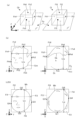
- FIGS. 8(a) to 8(c) are diagrams for explaining the details of the head model deformation process.
- the head model deformation process deforms the shape of the head model Mh so that it closely approximates the shape of the head of the subject S with high accuracy.
- FIG. 8(a) is a diagram for explaining the reference box Ch and the adjustment box Ci.
- the reference box Ch is generated according to the size of the target image Gs.
- the adjustment box Ci is generated according to the size of the head model Mh immediately before the head model deformation process is executed.
- the ratio Rhi between the size of the reference box Ch and the size of the adjustment box Ci is calculated, and the head model Mh is deformed (enlarged or reduced) according to the ratio Rhi.
- the reference box body Ch is a rectangular parallelepiped and is composed of a bottom surface Fh1, side surfaces Fh2 to Fh5, and a top surface Fh6.
- each surface Fh of the reference box body Ch is parallel to either the X-Y plane, the X-Z plane, or the Y-Z plane.
- the bottom surface Fh1 and top surface Fh6 are parallel to the X-Y plane
- side surfaces Fh2 and Fh5 are parallel to the Y-Z plane
- side surfaces Fh3 and Fh4 are parallel to the X-Z plane.
- the adjustment box Ci is a rectangular parallelepiped and is composed of a bottom surface Fi1, side surfaces Fi2 to Fi5, and a top surface Fi6.
- each surface Fi is parallel to either the X-Y plane, the X-Z plane, or the Y-Z plane.
- the bottom surface Fi1 and the top surface Fi6 are parallel to the X-Y plane
- the side surfaces Fi2 and Fi5 are parallel to the Y-Z plane
- the side surfaces Fi3 and Fi4 are parallel to the X-Z plane.
- FIG. 8(b) is a diagram for explaining the configuration for generating the reference box body Ch.
- the left part of FIG. 8(b) shows a conceptual diagram of the reference box body Ch as viewed from the Z-axis direction (top).
- the reference box body Ch is generated so that it can store the head image Gsh.
- FIG. 8(b) shows the head image Gsh stored in the reference box body Ch.
- the side Fh2 of the reference box body Ch passes through the point Ph2 where the X coordinate of the head image Gsh is maximum.
- the side Fh5 of the reference box body Ch passes through the point Ph5 where the X coordinate of the head image Gsh is minimum.
- the side Fh3 of the reference box body Ch passes through the point Ph3 where the Y coordinate of the head image Gsh is maximum
- the side Fh4 passes through the point Ph4 where the Y coordinate of the head image Gsh is minimum.
- each side surface Fh (2 to 5) of the reference box body Ch is generated so as to surround the head image Gsh on all four sides when viewed from the Z-axis direction.
- the right side of Figure 8(b) shows a conceptual diagram of the head image Gsh when viewed from the X-axis direction.
- the top surface Fh6 of the reference box body Ch passes through point Ph6 of the head image Gsh where the Z coordinate is maximum.
- each of the side surfaces Fh (2 to 5) and top surface Fh6 of the reference box body Ch is generated so as to be in contact with the target image Gh.
- the head image Gsh does not include the lower part of the target S
- the point (bottom end) where the Z coordinate of the head image Gsh is the minimum is different from the actual bottom end (Pah) of the target S. Therefore, if the bottom surface Fh1 of the reference box body Ch were generated at the point in the target image Gsh where the Z coordinate is the minimum, it may not be possible to deform the shape of the head model Mh to closely approximate the shape of the target S with high accuracy. In these cases, there is the inconvenience that the volume and height of the target S cannot be estimated with high accuracy.
- the applicant has focused on the fact that the lower end Pah of the subject S lying on the flat surface A is located on the flat surface A.
- FIG. 8(b) the lower part Sh of the head of the subject S that is missing from the head image Gs is shown by a dashed line.
- the reference plane Fa is generated at a position corresponding to the flat surface A. Therefore, even if the lower part Sh of the subject S is not included in the head image Gs, it can be assumed that the point corresponding to the lower end Pah of the lower part Sh in the three-dimensional image space is on the reference plane Fa.
- this embodiment employs a configuration in which the bottom surface Fh1 of the reference box body Ch is located on the reference surface Fa.
- the above configuration is a configuration in which the lower part Sh of the target S is assumed to be in contact with the flat surface A at its lower end Pah, and the volume of the target S including the lower part Sh that is missing in the target image Gs is estimated using the target image Gs.
- FIG. 8(c) is a diagram for explaining the configuration for generating the adjustment box Ci.
- FIG. 8(c) shows a conceptual diagram of the adjustment box Ci as viewed from the Z-axis direction (top).
- the adjustment box Ci is generated so that it can accommodate the head model Mh.
- the top surface Fi6 of the adjustment box Ci passes through the point Qi6 of the head model Mh where the Z coordinate is maximum.
- the side surface Fi2 of the adjustment box Ci passes through the point Qi2 of the head model Mh where the X coordinate is maximum, and the side surface Fi5 of the adjustment box Ci passes through the point Qi5 of the head model Mh where the X coordinate is minimum.
- the side surface Fi3 of the adjustment box Ci passes through the point Pi3 of the head model Mh where the Y coordinate is maximum, and the side surface Fi4 passes through the point Pi4 of the head model Mh where the Y coordinate is minimum.
- the head model Mh represents the entire target S including the lower part.
- the bottom surface Fi1 of the adjustment box Ci passes through the point Qi1 of the head model Mh where the Z coordinate is minimum.
- the information processing device 10 After determining the ratios Rhix, Rhiy, and Rhiz (sometimes collectively referred to as "ratio Rhi"), the information processing device 10 deforms (enlarges or reduces) the head model Mh using the ratio Rhi. Specifically, the information processing device 10 multiplies the head model Mh by Rhix in the X-axis direction, by Rhiy in the Y-axis direction, and by Rhiz in the Z-axis direction. According to the above head model deformation process, even if the lower part of the subject S is not photographed, the reference box body Ch is generated assuming that the lower end Pah of the subject S is in contact with the flat surface A, making it easier to approximate the shape of the head model Mh to the shape of the head of the subject S with high accuracy.
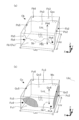
- FIGS. 9(a) and 9(b) are diagrams for explaining the details of the torso model deformation process.
- the shape of the torso model Mb is deformed using the reference box Cb and the adjustment box Cc, similar to the head model deformation process described above.
- the subject S in this embodiment is assumed to be a newborn, and newborns often wear disposable diapers.
- the waist image Gw in the torso image Gb will have a large area that represents the disposable diaper covering the waist of the newborn.
- the reference box body Cb in this embodiment is generated based on the chest image Gc in the torso image Gb.
- FIG. 9(a) is a diagram for explaining the reference box Cb.
- the reference box Cb is a rectangular parallelepiped and is generated so that it can store the chest image Gc.
- the reference box Cb is composed of a bottom surface Fb1, side surfaces Fb2 to Fb5, and a top surface Fb6.
- each of the above surfaces Fb (1 to 6) is parallel to either the X-Y plane, the X-Z plane, or the Y-Z plane.
- the bottom surface Fb1 and the top surface Fb6 are parallel to the X-Y plane
- the side surfaces Fb2 and Fb5 are parallel to the Y-Z plane
- the side surfaces Fb3 and Fb4 are parallel to the X-Z plane.
- the top surface Fb6 is in contact with point Pb6 in the chest image Gc, where the Z coordinate is maximum.
- the side surface Fb2 is in contact with point Pb2 in the chest image Gc, where the X coordinate is minimum
- the side surface Fb5 is in contact with point Pb5 in the chest image Gc, where the X coordinate is maximum.
- the side surface Fb4 is in contact with point Pb4 in the chest image Gc, where the Y coordinate is minimum
- the side surface Fb3 is in contact with point Pb3 in the chest image Gc, where the Y coordinate is maximum.
- a reference box body Cb is generated assuming that the lower end Pac of the subject S's chest is located on flat surface A (similar to the reference box body Ch shown in Figure 8(b) above).
- the lower portion Sc of the chest of the subject S is missing from the chest image Gc.
- the bottom surface Fb1 of the reference box body Cb is generated on the reference plane Fa (flat surface A) where the actual lower end portion Pac of the chest is located.
- FIG. 9(b) is a diagram for explaining the adjustment box Cc.
- the adjustment box Cc is a rectangular parallelepiped and is generated so that it can house the chest model Mc.
- the adjustment box Cc is composed of a bottom surface Fc1, side surfaces Fc2 to Fc5, and a top surface Fc6.
- each of the above surfaces Fc (1 to 6) is parallel to either the X-Y plane, the X-Z plane, or the Y-Z plane.
- the top surface Fc6 and the bottom surface Fc1 are parallel to the X-Y plane
- the side surfaces Fc2 and Fc5 are parallel to the Y-Z plane
- the side surfaces Fc3 and Fc4 are parallel to the X-Z plane.
- the top face Fc6 is in contact with the point Qc6 of the chest model Mc where the Z coordinate is maximum.
- the side face Fc2 is in contact with the point Qc2 of the chest model Mc where the X coordinate is minimum
- the side face Fc5 is in contact with the point Qc5 of the chest model Mc where the X coordinate is maximum.
- the side face Fc3 is in contact with the point Qc3 of the chest model Mc where the Y coordinate is maximum
- the side face Fc4 is in contact with the point Qc4 of the chest model Mc where the Y coordinate is minimum.
- the chest model Mc represents the overall shape of the target S including the lower part. Taking the above into consideration, the bottom face Fc1 of the adjustment box Cc passes through the lower end Qc1 of the chest model Mc where the Z coordinate is minimum.
- the information processing device 10 After determining the ratios Rbcx, Rbcy, and Rbcz (sometimes collectively referred to as "ratio Rbc"), the information processing device 10 deforms (enlarges and reduces) the torso model Mb (chest model Mc+waist model Mw) based on the ratio Rbc. Specifically, the information processing device 10 multiplies the torso model Mb by Rbcx in the X-axis direction, by Rbcy in the Y-axis direction, and by Rbcz in the Z-axis direction.
- the shape of the torso model Mb can be deformed to closely approximate the shape of the torso of the subject S with high accuracy by generating a reference box body Cb assuming that the lower end Pac of the chest of the subject S is in contact with the flat surface A.
- FIG. 10(a) is a diagram for explaining the volume estimation process.
- the volume estimation process the volume of the target S is estimated.
- the head model deformation process see FIGS. 8(a)-(c)
- torso model deformation process see FIGS. 9(a) and (b)
- arm model deformation process and leg model deformation process are used to deform the head model Mh, torso model Mb, arm model Ma, and leg model Ml so as to approximate the shapes of each part of the target S.
- the target model M is generated by combining each model after the above deformations.
- FIG. 10(a) shows a mock-up of the target model M.
- each cross section Mp shown in FIG. 10(a) is obtained by cutting the target model M parallel to the Y-Z plane while shifting the position in the X-axis direction.
- FIG. 10(a) shows two adjacent cross sections Mp. As shown in FIG. 10(a), adjacent cross sections Mp are separated by a "distance ⁇ x" in the X-axis direction. The distance ⁇ x is sufficiently small compared to the size of the target image Gs. When the distance ⁇ x is sufficiently small, the volume V of the target model M is calculated (approximated) by the following equation 2. Note that "An” in equation 2 means the area of the n-th cross section Mp from the tip of the target model M in the X-axis direction. Also, "N” in equation 2 means the total number of cross sections Mp.
- the shape (size) of the target model M is similar to the shape of the actual target S. Therefore, the volume V of the target model M calculated in the volume estimation process can be estimated as the volume of the actual target S.
- the information processing device 10 multiplies the volume V of the target model M by the average density D to calculate the weight W of the target S.
- FIG. 10(b) is a diagram for explaining the height estimation process.
- the height of the target model M is calculated, and the calculation result is estimated as the height of the target S.
- the information processing device 10 detects predetermined feature points in the target model M in the height estimation process.
- point Pa corresponding to the top of the head of the target S point Pb corresponding to the shoulder joint, point Pc corresponding to the hip joint, point Pd corresponding to the knee joint, and point Pe corresponding to the ankle are detected in the target model M.
- the technology described in Japanese Patent No. 6868875 can be adopted.
- the information processing device 10 When the information processing device 10 detects feature points in the target model M, it calculates the horizontal distance Lab from point Pa corresponding to the top of the head to point Pb corresponding to the shoulder joint. In addition, the information processing device 10 calculates the horizontal distance Lbc from point Pb corresponding to the shoulder joint to point Pc corresponding to the hip joint, the distance Lcd from point Pc corresponding to the hip joint to point Pd corresponding to the knee joint, and the distance Lde from point Pd corresponding to the knee joint to point Pe corresponding to the ankle.
- the information processing device 10 calculates the sum of the distances Lab, Lbc, Lcd, and Lde as the height H of the target model M.
- the height H of the target model M described above is estimated as the height of the target S represented by the target model M.
- the height estimation process can be modified as appropriate.
- the feature points detected from the target model M are not limited to the above examples, as long as they can measure the height of the target model M.
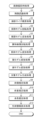
- FIG. 11 is a flowchart of the image capture processing executed by the information processing device 10.
- the image capture device 20 transmits image information Dg indicating the three-dimensional image G (including the target image Gs) to the information processing device 10.
- the information processing device 10 executes the image capture processing, for example, when it acquires (receives) the image information Dg.
- the trigger for executing the image capture processing can be changed as appropriate.
- the information processing device 10 executes an image recognition process (S0).
- image recognition process each object (including the target S) depicted in the three-dimensional image G indicated by the image information Dg is recognized.
- the information processing device 10 executes a head size approximation process (S1).
- head size approximation process the rough shape (size) of the head model Mh is determined (see FIG. 7(a) above).
- the information processing device 10 also executes a head model rotation process. In the head model rotation process, the orientation of the head model Mh is rotated (adjusted) in accordance with the orientation of the head image Gh (see FIG. 7(b) above).
- the information processing device 10 executes the head model deformation process (S3).
- the shape of the head model Mh is deformed so as to closely approximate the shape of the head of the subject S with high accuracy (see Figures 8(a) to (c) above).
- the information processing device 10 also executes a torso image rotation process (S4).
- the torso image rotation process the torso image Gsb is rotated so as to be parallel to the X-axis direction.
- the information processing device 10 executes a torso model deformation process (S5).
- the shape of the torso model Mb is deformed so as to closely approximate the shape of the torso of the target S with high accuracy (see Figures 9(a) and (b) above).
- the information processing device 10 executes an arm model deformation process (S6) to deform the shape of the arm model Ma so that it approximates the shape of the arm of the subject S.
- the information processing device 10 also executes a leg model deformation process (S7) to deform the shape of the leg model Ml so that it approximates the shape of the leg of the subject S.
- a target model M is generated by combining a head model Mh deformed in the most recent head model deformation process, a torso model Mb deformed in the torso model deformation process, an arm model Ma deformed in the arm model deformation process, and a leg model Ml deformed in the leg model deformation process.
- the information processing device 10 executes a volume estimation process (S9).
- the volume estimation process the volume of the object model M generated in the most recent object model generation process is calculated (see FIG. 10(a) above).
- the information processing device 10 executes a weight estimation process (S10).
- the weight estimation process the information processing device 10 multiplies the volume of the object model M calculated in the most recent volume estimation process by the average density, and stores the calculation result as the weight W of the object S.
- the information processing device 10 executes a height estimation process (S11).
- the height estimation process the height of the target model M generated in the most recent target model generation process is measured, and the measurement result is stored as the height H of the target S (see FIG. 10(b) above).
- the information processing device 10 executes a biometric information display process (S12).
- the weight W of the target S calculated in the most recent weight estimation process and the height H of the target S calculated in the height estimation process are displayed, for example, on the monitor 104 of the incubator.
- the information processing device 10 ends the image capture process.
- Medical procedures in which a medical tube is inserted into a subject have been known for some time.
- one such medical procedure is the insertion of a gastric tube into a subject (including patients and newborns) who cannot orally ingest food.
- the gastric tube is inserted through the nostril, passes through the esophagus, and reaches the inside of the stomach.
- the appropriate length of the gastric tube varies for each subject. Therefore, traditionally, the appropriate length of the gastric tube has been estimated as the sum of the length from the ear hole to the space between the eyebrows on the subject's surface and the length from the navel to the middle of the xiphoid process.
- the second embodiment aims to make it possible to estimate the appropriate length of a medical tube (e.g., a gastric tube) to be inserted into the object without touching the object.
- a medical tube e.g., a gastric tube
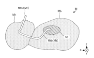
- FIG. 12 is a conceptual diagram of the head model Mh and torso model Mb of the second embodiment. For the sake of explanation, the head model Mh and torso model Mb are shown in combination in FIG. 12. FIG. 12 is also a cross-sectional view of the head model Mh and torso model Mb cut horizontally on the X-Z plane.
- a target image Gs (three-dimensional image) representing the target S is captured by the imaging device 20.
- the head model Mh, torso model Mb, arm model Ma and leg model Ml are deformed based on the target image Gs to generate the target model M.
- the volume of the target model M is estimated as the volume of the target S.
- the weight of the target S is calculated from the estimated volume.
- the height of the target model M is estimated as the height of the target S.
- the target model M in the second embodiment is configured to include a tube model Mt (Mth, Mtb).
- the tube model Mt represents a medical tube of an appropriate length to be inserted into the target S represented by the combination of the head model Mh and the torso model Mb.
- the tube model Mt represents the shape of a gastric tube (an example of a medical tube) when inserted into the target S.
- the gastric tube when inserted into the target S bends in the path from the nostril through the esophagus to the stomach.
- the tube model Mt bends in the same way as the gastric tube when inserted into the target S.
- the tube model Mt is provided in a region of the combination of the head model Mh and the torso model Mb that corresponds to the medical tube inserted into the subject S.
- the tube model Mt representing a gastric tube is located in a region that corresponds to the path from the nostril of the subject S through the esophagus to the inside of the stomach.
- Figure 12 shows the region St that corresponds to the stomach of the subject S.
- the end of the tube model Mt on the torso model Mb side is located inside the region St.
- the tube model Mt includes a first tube model Mth provided inside the head model Mh and a second tube model Mtb provided inside the torso model Mb.
- a head model deformation process (see FIGS. 8(a) to (c)) is executed, and the head model Mh is deformed to the size of the head of the target S.
- the first tube model Mth is deformed as an image integrated with the head model Mh.
- a torso model deformation process see FIGS.
- the torso model Mb is deformed to the size of the torso of the target S.
- the second tube model Mtb is deformed as an image integrated with the torso model Mb.
- a target model M that approximates the shape of the target S is generated.
- the target model M also includes a tube model Mt (a combination of a first tube model Mth and a second tube model Mtb) that is deformed (stretched) to the length to be inserted into the target S. Therefore, by calculating the length of the tube model Mt in the target model M, the length of the medical tube to be inserted into the target S can be determined.
- the weight of the target S is estimated by generating the target model M and multiplying the volume of the target model M by the average density.
- the configuration for estimating the weight of the target S is not limited to the above example.
- a target model M is generated in the same manner as in the first embodiment described above. Furthermore, in the third embodiment, the length of a specific portion of the target model M is identified as an explanatory variable X for estimating the weight of the target S.
- the explanatory variable X is the length of a specific portion of the target model M that has a causal relationship with the weight of the target S.
- n+1 (n is a positive integer) explanatory variables (X0, X1, X2, X3...Xn) are identified. For example, the body length, chest circumference, chest width, chest length, leg length, hand length, etc. of the target model M are identified as explanatory variables X.
- the information processing device 10 after identifying each explanatory variable X, calculates (estimates) the weight W of the subject S by substituting the explanatory variable X into the following equation 3.
- the coefficients k0 to kn in equation 3 are determined, for example, by multiple regression analysis.
- the method of determining the coefficients k0 to kn is not limited to multiple regression analysis.
- the target model M may include a tube model Mt.
- the configuration for estimating the weight W of the target S using explanatory variables is not limited to the above example.
- a machine learning model trained by machine learning using teacher data of the explanatory variables X and the weight W may be used.
- a machine learning model multiple decision tree models
- the weight W of the target S is determined (estimated).
- the arm model deformation process can be modified as appropriate.
- the arm image Gsa includes a first arm image Gsa1 representing the area from the shoulder to the elbow of the subject S, and a second arm image Gsa2 representing the area from the elbow to the fingertips.
- the arm model Ma includes a first arm model Ma1 representing the area from the shoulder to the elbow of the subject S, and a second arm model Ma2 representing the area from the elbow to the fingertips.
- the information processing device 10 approximates the first arm image Gsa1 to a cylinder. Specifically, the information processing device 10 identifies the orientation of the first arm image Gsa1 (hereinafter, "direction vector V") by principal component analysis. The information processing device 10 uses the least squares method to generate a cylinder (hereinafter, "cylinder Cg") whose center line is parallel to the direction vector V and whose side surface approximately overlaps with the first arm image Gsa1.
- cylinder Cg cylinder whose center line is parallel to the direction vector V and whose side surface approximately overlaps with the first arm image Gsa1.
- the information processing device 10 generates a cylinder (hereinafter "cylinder Cm") that is similar to the first arm model Ma1 in a similar manner to the method of generating the cylinder Cg from the first arm image Gsa1.
- the information processing device 10 calculates the ratio "Rg/Rm” by dividing the diameter Rg (thickness) of the bottom surface of the cylinder Cg by the diameter Rm of the bottom surface of the cylinder Cm, and enlarges or reduces the thickness of the first arm model Ma1 according to the ratio "Rg/Rm".
- the information processing device 10 also calculates the ratio "Tg/Tm" by dividing the height Tg (length) of the cylinder Cg by the height Tm of the cylinder Cm, and enlarges or reduces the length of the first arm model Ma1 according to the ratio "Tg/Tm".
- the shape of the first arm model Ma1 is deformed so as to approximate the shape of the upper arm of the subject S.
- the shape of the second arm model Ma2 is deformed using the second arm image Gsa2.
- the leg model deformation process can be modified as appropriate.
- the leg image Gsl includes a first leg image Gsl1 representing the leg from the base to the knee, and a second leg image Gsl2 representing the leg from the knee to the toes.
- Each of the above images is distinguished by segmentation technology.
- the leg model Ml includes a first leg model Ml1 representing the thigh of the subject S, and a second leg model Ml2 representing the part from the knee to the toes.
- the information processing device 10 uses the first leg image Gsl1 to deform the shape of the first leg model Ml1 in a manner similar to the manner in which the shape of the first arm model Ma1 in the above-mentioned modified example (1) was deformed. With the above configuration, the shape of the first leg model Ml1 is deformed so as to approximate the shape of the thigh of the target S. Furthermore, the information processing device 10 uses the second leg image Gsl2 to deform the shape of the second leg model Ml2 in a manner similar to the manner in which the shape of the first arm model Ma1 was deformed. With the above configuration, the shape of the second leg model Ml2 is deformed so as to approximate the shape of the leg from the knee to the toes of the target S.
- the method of determining the reference plane Fa can be changed as appropriate.
- a configuration in which the imaging device 20 is fixed to an incubator is conceivable.
- the distance from the imaging device 20 to the flat surface A is constant, and the reference plane Fa through which the flat image Ga passes is common regardless of the three-dimensional image G.
- the reference plane Fa can be stored in advance in the information processing device 10. Therefore, there is an advantage in that the process for identifying the reference plane Fa from the flat image Ga can be omitted.
- the head size approximation process estimates the shape (size) of the head of the target S by approximating the head image Gsh as a sphere.
- the head image Gsh is approximated as an elliptical sphere.
- FIGS. 13(a) and 13(b) are diagrams for explaining a modified example in which the head image Gsh can be approximated by an ellipse.
- each cross section of the head image Gsh cut parallel to the Z-X plane and at equal intervals in the Y-axis direction is approximated by an ellipse.
- the model Mh is then deformed (enlarged or reduced) to the size of the image generated by superimposing the approximated ellipses.
- FIG. 13(a) shows the head image Gsh before it is approximated by an ellipse.
- the reference plane Fa flat plane A
- the shape of the head of the subject S missing from the head image Gsh is shown by a dashed line.
- subject S newborn baby
- subject S inside an incubator may have medical tubes attached.
- part of the head is occluded by subject S's hand (arm) or tube, and the occluded part is missing from the head image Gsh.
- the head image Gsh below the arm image Gsa is missing.
- the arm image Gsa may be recognized as part of the head image Gsh.
- the present modified example has a configuration that suppresses the above inconveniences. The above configuration will be described in detail below.
- the ellipse with a larger evaluation value V i can be estimated to be more similar to the actual shape of the head of the target S.
- a case is assumed in which an equation E i of an ellipse is obtained by combining points Pa1 to Pa6 in the head image Gsh, and an equation E i of another ellipse is obtained by combining points Pb1 to Pb6.
- FIG. 13(a) a case is assumed in which an equation E i of an ellipse is obtained by combining points Pa1 to Pa6 in the head image Gsh, and an equation E i of another ellipse is obtained by combining points Pb1 to Pb6.
- the evaluation value Vi of n ellipses is calculated, and the ellipse with the largest evaluation value Vi is estimated to be the ellipse that represents the actual shape of the head of the target S.
- FIG. 13B is a flowchart of the ellipse approximation process.
- the ellipse approximation process determines an equation E i of an ellipse that approximates the shape of the head of the target S. Specifically, when the ellipse approximation process is started, the information processing device 10 randomly determines six points P in the target image Gs (S101), and calculates an equation E i of an ellipse that passes through each of the points P (S102). The information processing device 10 also obtains the number of points on the target image Gs i that are located on the ellipse of the equation E i as an evaluation value V i (S103).
- the information processing device 10 determines whether or not the evaluation values V i of n ellipses have been obtained (S104). If the number of ellipses for which the evaluation values V i have been obtained is less than n (S104: No), the information processing device 10 repeatedly executes the above-mentioned steps S101 to S104. On the other hand, if the number of ellipses for which the evaluation value V i has been calculated reaches n (S104: Yes), the information processing device 10 stores the equation E i of the ellipse having the maximum evaluation value V i among the n ellipses (S105) and terminates the ellipse approximation process.
- the length of the radius of the ellipse obtained by the ellipse approximation process should be half the length from the reference plane Fa to the vertex of the target image Gs (Lc in FIG. 13(a)). Therefore, the difference (error) between the length of the radius of the ellipse obtained by the ellipse approximation process and the length Lc may be calculated, and if the difference exceeds a predetermined threshold, an error may be determined. If an error is determined, the ellipse approximation process may be executed again. Also, the inclination of the ellipse may be calculated from the equation Ei , and the orientation of the ellipse may be adjusted according to the calculation result.
- the estimated information of the target S is not limited to weight and height.
- the information processing device 10 (measurement unit 16) may be configured to estimate the head circumference, chest circumference, waist circumference, arm thickness, and leg thickness of the target S.
- the information processing device 10 may be configured to measure the head circumference, chest circumference, waist circumference, arm thickness, and leg thickness of the generated target model M, and estimate each measurement result as the head circumference, chest circumference, waist circumference, arm thickness, and leg thickness of the target S.
- the information processing device (10) of this aspect includes an acquisition unit (11) that acquires image information (Dg) showing a three-dimensional image (G) of a target (S) lying on a flat surface (A) taken from above, a recognition unit (12) that recognizes a target image (Gs) that represents the target among the objects displayed in the three-dimensional image, and an estimation unit (13) that estimates the shape of the target, including the lower part missing in the target image, by using the target image, assuming that the lower part of the target is in contact with the flat surface, and calculates the physical information (volume, weight, height, etc.) of the target using the estimated shape of the target.
- Dg image information showing a three-dimensional image (G) of a target (S) lying on a flat surface (A) taken from above
- a recognition unit (12) that recognizes a target image (Gs) that represents the target among the objects displayed in the three-dimensional image
- an estimation unit (13) that estimates the shape of the target, including the lower part missing in the target image, by
- the physical information of the target can be estimated without touching the target.
- the physical information of the target can be estimated with high accuracy. Note that "estimating the shape of the target" in the present invention is sufficient as long as the physical information of the target S can be calculated, and is not limited to estimating the shape of the target S in detail.
- the information processing device of this aspect includes a storage unit (14) that stores model information indicating the shape of a target model (such as a head model), a recognition unit recognizes a flat image (Ga) that represents a flat surface (A) in a three-dimensional image, and an estimation unit identifies a reference surface (Fa) that passes through the flat image, and deforms the model according to the ratio of the distance (Lhz, Lbz) from a target point (Ph6 in FIG. 8(b), Pb6 in FIG.
- a storage unit (14) that stores model information indicating the shape of a target model (such as a head model), a recognition unit recognizes a flat image (Ga) that represents a flat surface (A) in a three-dimensional image, and an estimation unit identifies a reference surface (Fa) that passes through the flat image, and deforms the model according to the ratio of the distance (Lhz, Lbz) from a target point (Ph6 in FIG. 8(b), Pb
- the information processing device calculates the weight of the subject as physical information, and can estimate the weight of the subject without touching the subject.
- the information processing device calculates the height of the target as physical information, and can estimate the height of the target without touching the target.
- the model includes a tube model (Mt) representing a medical tube (e.g., a gastric tube) inserted into a target, and the estimation unit is capable of deforming the model and the tube model together when deforming models other than the tube model (head model Mh, chest model Mb). According to this aspect, it is possible to estimate the optimal length of the medical tube without touching the target.
- Mt tube model representing a medical tube
- the estimation unit is capable of deforming the model and the tube model together when deforming models other than the tube model (head model Mh, chest model Mb).
- the information processing device (10) of this embodiment includes an acquisition unit (11) for acquiring image information (Dg) showing a three-dimensional image (G) of a subject (S) lying on a flat surface (A) taken from above, a recognition unit (12) for recognizing a subject image (Gs) showing the subject and a flat image (Ga) showing the flat surface among the images showing each object displayed in the three-dimensional image, a storage unit (14) for storing model information showing the shape of the subject model, and an estimation unit (13) for estimating the subject's weight, and the estimation unit specifies a reference plane passing through the flat image, deforms the model according to the ratio of the distance in the vertical axis direction from a subject point in the subject image to the reference plane and the distance in the vertical axis direction from a corresponding point in the model corresponding to the subject point to the lower end of the model, specifies the length of a predetermined part of the deformed model as an explanatory variable for estimating the subject's weight, and estimates
- the method for estimating the weight of a newborn includes the steps of taking a three-dimensional image of the newborn, estimating the shape of the newborn from the three-dimensional image by a computer (S1 to S9 in FIG. 11), and estimating the weight of the newborn from the estimated shape by a computer (S10 in FIG. 11).
- a computer S1 to S9 in FIG. 11
- a computer S10 in FIG. 11
- the act of touching the newborn to measure physical information with a weighing scale can be considered an invasive act.
- the weight of the newborn is estimated without touching the newborn, which has the advantage of reducing the number of invasive acts.
- 10 information processing device
- 11 acquisition unit
- 12 recognition unit
- 13 estimation unit
- 14 storage unit
- 15 calculation unit
- 16 measurement unit
- 20 imaging device.
Landscapes
- Health & Medical Sciences (AREA)
- Physics & Mathematics (AREA)
- Engineering & Computer Science (AREA)
- Life Sciences & Earth Sciences (AREA)
- Biomedical Technology (AREA)
- Heart & Thoracic Surgery (AREA)
- General Physics & Mathematics (AREA)
- Dentistry (AREA)
- Oral & Maxillofacial Surgery (AREA)
- Computer Vision & Pattern Recognition (AREA)
- Biophysics (AREA)
- Pathology (AREA)
- Geometry (AREA)
- Theoretical Computer Science (AREA)
- Medical Informatics (AREA)
- Molecular Biology (AREA)
- Surgery (AREA)
- Animal Behavior & Ethology (AREA)
- General Health & Medical Sciences (AREA)
- Public Health (AREA)
- Veterinary Medicine (AREA)
- Image Processing (AREA)
- Measurement Of The Respiration, Hearing Ability, Form, And Blood Characteristics Of Living Organisms (AREA)
- Image Analysis (AREA)
Priority Applications (2)
| Application Number | Priority Date | Filing Date | Title |
|---|---|---|---|
| JP2024561393A JP7756972B2 (ja) | 2022-12-01 | 2023-11-20 | 情報処理装置及び新生児の体重の推定方法 |
| JP2025122203A JP2025142234A (ja) | 2022-12-01 | 2025-07-22 | 情報処理装置、情報処理方法及びプログラム |
Applications Claiming Priority (2)
| Application Number | Priority Date | Filing Date | Title |
|---|---|---|---|
| JP2022192854 | 2022-12-01 | ||
| JP2022-192854 | 2022-12-01 |
Publications (1)
| Publication Number | Publication Date |
|---|---|
| WO2024116936A1 true WO2024116936A1 (ja) | 2024-06-06 |
Family
ID=91323730
Family Applications (1)
| Application Number | Title | Priority Date | Filing Date |
|---|---|---|---|
| PCT/JP2023/041637 Ceased WO2024116936A1 (ja) | 2022-12-01 | 2023-11-20 | 情報処理装置及び新生児の体重の推定方法 |
Country Status (2)
| Country | Link |
|---|---|
| JP (2) | JP7756972B2 (https=) |
| WO (1) | WO2024116936A1 (https=) |
Citations (5)
| Publication number | Priority date | Publication date | Assignee | Title |
|---|---|---|---|---|
| WO2020111269A1 (ja) * | 2018-11-30 | 2020-06-04 | Arithmer株式会社 | 寸法データ算出装置、製品製造装置、情報処理装置、及びシルエット画像生成装置、端末装置 |
| JP2020181400A (ja) * | 2019-04-25 | 2020-11-05 | キヤノン株式会社 | 画像処理装置、撮像装置、制御方法、プログラム及び記録媒体 |
| WO2020260631A1 (en) * | 2019-06-26 | 2020-12-30 | Viking Genetics Fmba | Weight determination of an animal based on 3d imaging |
| WO2021084677A1 (ja) * | 2019-10-31 | 2021-05-06 | 日本電気株式会社 | 画像処理装置、画像処理方法及び画像処理プログラムが格納された非一時的なコンピュータ可読媒体 |
| JP2022059493A (ja) * | 2020-10-01 | 2022-04-13 | 株式会社Preferred Networks | モデル生成方法、モデル生成装置、画像処理方法及び画像処理装置 |
Family Cites Families (3)
| Publication number | Priority date | Publication date | Assignee | Title |
|---|---|---|---|---|
| JP3738291B2 (ja) * | 2003-06-09 | 2006-01-25 | 住友大阪セメント株式会社 | 三次元形状測定装置 |
| FR3099360B1 (fr) * | 2019-07-29 | 2023-06-30 | Thales Sa | Simulation amelioree du deploiement d'une endoprothese en temps reel |
| US11727828B2 (en) * | 2020-02-19 | 2023-08-15 | Arizona Board Of Regents On Behalf Of The University Of Arizona | Virtual reality environment adapted to model the mammalian airway for intubation and airway management training |
-
2023
- 2023-11-20 WO PCT/JP2023/041637 patent/WO2024116936A1/ja not_active Ceased
- 2023-11-20 JP JP2024561393A patent/JP7756972B2/ja active Active
-
2025
- 2025-07-22 JP JP2025122203A patent/JP2025142234A/ja active Pending
Patent Citations (5)
| Publication number | Priority date | Publication date | Assignee | Title |
|---|---|---|---|---|
| WO2020111269A1 (ja) * | 2018-11-30 | 2020-06-04 | Arithmer株式会社 | 寸法データ算出装置、製品製造装置、情報処理装置、及びシルエット画像生成装置、端末装置 |
| JP2020181400A (ja) * | 2019-04-25 | 2020-11-05 | キヤノン株式会社 | 画像処理装置、撮像装置、制御方法、プログラム及び記録媒体 |
| WO2020260631A1 (en) * | 2019-06-26 | 2020-12-30 | Viking Genetics Fmba | Weight determination of an animal based on 3d imaging |
| WO2021084677A1 (ja) * | 2019-10-31 | 2021-05-06 | 日本電気株式会社 | 画像処理装置、画像処理方法及び画像処理プログラムが格納された非一時的なコンピュータ可読媒体 |
| JP2022059493A (ja) * | 2020-10-01 | 2022-04-13 | 株式会社Preferred Networks | モデル生成方法、モデル生成装置、画像処理方法及び画像処理装置 |
Also Published As
| Publication number | Publication date |
|---|---|
| JP7756972B2 (ja) | 2025-10-21 |
| JP2025142234A (ja) | 2025-09-30 |
| JPWO2024116936A1 (https=) | 2024-06-06 |
Similar Documents
| Publication | Publication Date | Title |
|---|---|---|
| CN109008944B (zh) | 视线计测装置、rom及视线计测方法 | |
| US7862172B2 (en) | Gaze direction measuring method and gaze direction measuring device | |
| KR101930652B1 (ko) | 보행 해석 시스템 및 기록 매체에 기록된 컴퓨터 프로그램 | |
| JPWO2008007781A1 (ja) | 視線方向検出装置および視線方向検出方法 | |
| US20120310075A1 (en) | Medical measurement system and method | |
| JP7756393B2 (ja) | 姿勢自動評価装置、姿勢自動評価方法及び姿勢自動評価プログラム | |
| JP7030317B2 (ja) | 瞳孔検出装置及び瞳孔検出方法 | |
| KR20140003265A (ko) | 인체관절 움직임 각도의 측정방법 | |
| JP7283841B2 (ja) | 視線計測装置 | |
| WO2021084687A1 (ja) | 画像処理装置、画像処理方法及び画像処理プログラムが格納された非一時的なコンピュータ可読媒体 | |
| WO2020261403A1 (ja) | 身長推定装置、身長推定方法及びプログラムが格納された非一時的なコンピュータ可読媒体 | |
| CN116363759A (zh) | 一种基于3d骨骼点的人体坐姿检测方法 | |
| US20240257392A1 (en) | Fall Detection and Prevention System for Alzheimer's, Dementia, and Diabetes | |
| JP7756972B2 (ja) | 情報処理装置及び新生児の体重の推定方法 | |
| CN116348909A (zh) | 姿势检测装置、姿势检测方法及睡相判定方法 | |
| KR101788960B1 (ko) | 관절 가동성 자동측정장치 및 이를 이용한 관절 가동성 자동측정방법 | |
| CN117115922A (zh) | 坐位体前屈评测方法、系统、电子设备和存储介质 | |
| JPWO2024116936A5 (https=) | ||
| JP2011118767A (ja) | 表情モニタリング方法および表情モニタリング装置 | |
| KR102456055B1 (ko) | 반복 운동의 동작 훈련을 위한 정량적 자세 분석 및 평가 장치 및 방법 | |
| JP7620372B1 (ja) | 運動評価装置、運動評価方法、及び運動評価プログラム | |
| US11263780B2 (en) | Apparatus, method, and program with verification of detected position information using additional physical characteristic points | |
| JPWO2016159255A1 (ja) | 口領域検出装置及び口領域検出方法 | |
| JPWO2024166600A5 (ja) | 学習モデル生成装置、学習モデル生成方法、及びプログラム | |
| CN119600677B (zh) | 一种体态检测方法、存储介质、装置及终端设备 |
Legal Events
| Date | Code | Title | Description |
|---|---|---|---|
| 121 | Ep: the epo has been informed by wipo that ep was designated in this application |
Ref document number: 23897584 Country of ref document: EP Kind code of ref document: A1 |
|
| DPE1 | Request for preliminary examination filed after expiration of 19th month from priority date (pct application filed from 20040101) | ||
| WWE | Wipo information: entry into national phase |
Ref document number: 2024561393 Country of ref document: JP |
|
| NENP | Non-entry into the national phase |
Ref country code: DE |
|
| 122 | Ep: pct application non-entry in european phase |
Ref document number: 23897584 Country of ref document: EP Kind code of ref document: A1 |