WO2024111506A1 - 固体電解コンデンサ - Google Patents
固体電解コンデンサ Download PDFInfo
- Publication number
- WO2024111506A1 WO2024111506A1 PCT/JP2023/041322 JP2023041322W WO2024111506A1 WO 2024111506 A1 WO2024111506 A1 WO 2024111506A1 JP 2023041322 W JP2023041322 W JP 2023041322W WO 2024111506 A1 WO2024111506 A1 WO 2024111506A1
- Authority
- WO
- WIPO (PCT)
- Prior art keywords
- layer
- solid electrolyte
- electrolytic capacitor
- polymer
- solid electrolytic
- Prior art date
- Legal status (The legal status is an assumption and is not a legal conclusion. Google has not performed a legal analysis and makes no representation as to the accuracy of the status listed.)
- Ceased
Links
Images
Classifications
-
- H—ELECTRICITY
- H01—ELECTRIC ELEMENTS
- H01G—CAPACITORS; CAPACITORS, RECTIFIERS, DETECTORS, SWITCHING DEVICES, LIGHT-SENSITIVE OR TEMPERATURE-SENSITIVE DEVICES OF THE ELECTROLYTIC TYPE
- H01G9/00—Electrolytic capacitors, rectifiers, detectors, switching devices, light-sensitive or temperature-sensitive devices; Processes of their manufacture
- H01G9/15—Solid electrolytic capacitors
-
- H—ELECTRICITY
- H01—ELECTRIC ELEMENTS
- H01G—CAPACITORS; CAPACITORS, RECTIFIERS, DETECTORS, SWITCHING DEVICES, LIGHT-SENSITIVE OR TEMPERATURE-SENSITIVE DEVICES OF THE ELECTROLYTIC TYPE
- H01G9/00—Electrolytic capacitors, rectifiers, detectors, switching devices, light-sensitive or temperature-sensitive devices; Processes of their manufacture
-
- H—ELECTRICITY
- H01—ELECTRIC ELEMENTS
- H01G—CAPACITORS; CAPACITORS, RECTIFIERS, DETECTORS, SWITCHING DEVICES, LIGHT-SENSITIVE OR TEMPERATURE-SENSITIVE DEVICES OF THE ELECTROLYTIC TYPE
- H01G9/00—Electrolytic capacitors, rectifiers, detectors, switching devices, light-sensitive or temperature-sensitive devices; Processes of their manufacture
- H01G9/0029—Processes of manufacture
- H01G9/0036—Formation of the solid electrolyte layer
-
- H—ELECTRICITY
- H01—ELECTRIC ELEMENTS
- H01G—CAPACITORS; CAPACITORS, RECTIFIERS, DETECTORS, SWITCHING DEVICES, LIGHT-SENSITIVE OR TEMPERATURE-SENSITIVE DEVICES OF THE ELECTROLYTIC TYPE
- H01G9/00—Electrolytic capacitors, rectifiers, detectors, switching devices, light-sensitive or temperature-sensitive devices; Processes of their manufacture
- H01G9/004—Details
- H01G9/022—Electrolytes; Absorbents
- H01G9/025—Solid electrolytes
-
- H—ELECTRICITY
- H01—ELECTRIC ELEMENTS
- H01G—CAPACITORS; CAPACITORS, RECTIFIERS, DETECTORS, SWITCHING DEVICES, LIGHT-SENSITIVE OR TEMPERATURE-SENSITIVE DEVICES OF THE ELECTROLYTIC TYPE
- H01G9/00—Electrolytic capacitors, rectifiers, detectors, switching devices, light-sensitive or temperature-sensitive devices; Processes of their manufacture
- H01G9/004—Details
- H01G9/022—Electrolytes; Absorbents
- H01G9/025—Solid electrolytes
- H01G9/028—Organic semiconducting electrolytes, e.g. TCNQ
-
- H—ELECTRICITY
- H01—ELECTRIC ELEMENTS
- H01G—CAPACITORS; CAPACITORS, RECTIFIERS, DETECTORS, SWITCHING DEVICES, LIGHT-SENSITIVE OR TEMPERATURE-SENSITIVE DEVICES OF THE ELECTROLYTIC TYPE
- H01G9/00—Electrolytic capacitors, rectifiers, detectors, switching devices, light-sensitive or temperature-sensitive devices; Processes of their manufacture
- H01G9/004—Details
- H01G9/04—Electrodes or formation of dielectric layers thereon
- H01G9/042—Electrodes or formation of dielectric layers thereon characterised by the material
- H01G9/045—Electrodes or formation of dielectric layers thereon characterised by the material based on aluminium
-
- H—ELECTRICITY
- H01—ELECTRIC ELEMENTS
- H01G—CAPACITORS; CAPACITORS, RECTIFIERS, DETECTORS, SWITCHING DEVICES, LIGHT-SENSITIVE OR TEMPERATURE-SENSITIVE DEVICES OF THE ELECTROLYTIC TYPE
- H01G9/00—Electrolytic capacitors, rectifiers, detectors, switching devices, light-sensitive or temperature-sensitive devices; Processes of their manufacture
- H01G9/004—Details
- H01G9/07—Dielectric layers
-
- H—ELECTRICITY
- H01—ELECTRIC ELEMENTS
- H01G—CAPACITORS; CAPACITORS, RECTIFIERS, DETECTORS, SWITCHING DEVICES, LIGHT-SENSITIVE OR TEMPERATURE-SENSITIVE DEVICES OF THE ELECTROLYTIC TYPE
- H01G9/00—Electrolytic capacitors, rectifiers, detectors, switching devices, light-sensitive or temperature-sensitive devices; Processes of their manufacture
- H01G9/26—Structural combinations of electrolytic capacitors, rectifiers, detectors, switching devices, light-sensitive or temperature-sensitive devices with each other
Definitions
- This disclosure relates to solid electrolytic capacitors.
- a solid electrolytic capacitor comprises a solid electrolytic capacitor element, a resin exterior body or case that seals the solid electrolytic capacitor element, and an external electrode that is electrically connected to the solid electrolytic capacitor element.
- the solid electrolytic capacitor element comprises, for example, an anode body, a dielectric layer formed on the surface of the anode body, and a cathode portion that covers at least a portion of the dielectric layer.
- the cathode portion includes a conductive polymer (e.g., a conjugated polymer and a dopant) that covers at least a portion of the dielectric layer.
- the conductive polymer is also referred to as a solid electrolyte.
- Solid electrolytes can be formed using in situ polymerization, such as chemical polymerization or electrolytic polymerization. However, from the viewpoint of being able to easily form solid electrolytes, a method that uses a liquid dispersion containing a conjugated polymer and a dopant is often used to form solid electrolytes.
- Patent Document 1 proposes a method for manufacturing an electrolytic capacitor, which includes a step of impregnating an anode body having a dielectric film formed on its surface with a first dispersion solution containing particles of a first conductive polymer and a first solvent, and then impregnating the anode body with a second dispersion solution containing particles of a second conductive polymer and a second solvent, the pH of the first dispersion solution being closer to 7 than the pH of the second dispersion solution.
- the capacitor element includes an anode foil including a porous portion at least on the surface, a dielectric layer covering at least a portion of the anode foil, and a solid electrolyte layer covering at least a portion of the dielectric layer.
- the solid electrolyte layer includes a first polymer component including a conjugated polymer and a second polymer component including a polymer anion. In the Raman spectrum of the surface layer of the solid electrolyte layer, a peak specific to the first polymer component is observed. When the rated voltage of the solid electrolytic capacitor is Rv (V), the average thickness T of the dielectric layer is 2.50 ⁇ Rv (nm) or more.
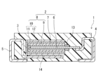
- FIG. 1 is a schematic cross-sectional view of a solid electrolytic capacitor according to an embodiment of the present disclosure.
- a solid electrolytic capacitor includes at least one capacitor element.
- the capacitor element includes an anode foil including a porous portion at least on the surface, a dielectric layer covering at least a portion of the anode foil, and a solid electrolyte layer covering at least a portion of the dielectric layer.
- the solid electrolyte layer includes a first polymer component including a conjugated polymer, and a second polymer component including a polymer anion.
- a peak specific to the first polymer component is observed.
- the average thickness T of the dielectric layer is 2.50 x Rv (unit: nm) or more.
- the solid electrolyte layer may contain sulfur (S) elements, and the anode foil may contain aluminum (Al) elements.
- the solid electrolyte layer has a first portion filled in the voids of the porous portion in the anode foil having a dielectric layer, and a second portion disposed outside the anode foil from the main surface of the anode foil having a dielectric layer.
- the abundance ratio of S elements in the porous portion may be 0.5% or more when the abundance ratio of Al elements in the porous portion is set to 100%. In this case, the decrease in capacity when charging and discharging is repeated can be further suppressed.
- the S element is mainly derived from the conjugated polymer and dopant that constitute the solid electrolyte.
- polythiophene-based conjugated polymers contain S elements in thiophene rings, and dopants contain S elements derived from anionic groups such as sulfo groups.
- anode foils containing Al elements are mainly made of aluminum or aluminum alloys, and the dielectric layer is made of aluminum oxide. Therefore, a relatively large abundance ratio of S elements compared to the abundance ratio of Al elements in the porous portion means that the proportion of solid electrolyte contained in the porous portion is relatively large (in other words, the filling rate of the solid electrolyte in the voids of the porous portion is high).
- the relatively high S element content in the porous portion as described above can be obtained, for example, by forming a dielectric layer on the surface of an anode foil that contains Al and at least a porous portion on the surface, immersing the anode foil having the obtained dielectric layer on its surface in a polymerization solution containing a precursor of a conjugated polymer and a polymer anion containing an S element, and electropolymerizing the anode foil at a relatively low polymerization potential in a three-electrode system.
- the polymerization of the precursor of the conjugated polymer gradually progresses in the presence of a polymer anion that is relatively stable as a dopant, and a conductive polymer in which the conjugated polymer and the polymer anion interact with each other is generated, forming a dense solid electrolyte. Since the precursor and the polymer anion are dissolved in the polymerization solution, they easily penetrate deep into the fine voids in the porous portion. Therefore, polymerization easily progresses not only near the opening of the voids but also in the deep parts of the voids. Therefore, it is believed that a high filling rate of the solid electrolyte in the voids can be obtained.
- the polymerization of the precursor of the conjugated polymer proceeds while interacting with the polymer anion, and in addition, the conjugated polymer formed is easily oriented with high precision.
- the polymer anion is relatively uniformly dispersed, and a relatively high doping rate is easily obtained.
- the solid electrolyte in the first portion has high conductivity, and dedoping or deterioration of the conjugated polymer is unlikely to occur even if the charge and discharge are repeated.
- the abundance ratio of the S element in the porous portion is low, for example, less than 0.5%. This is thought to be because, as described above, even when a liquid dispersion is used, the filling rate of the solid electrolyte in the porous portion is low.
- Three-electrode electropolymerization is carried out using three electrodes: an anode foil with a dielectric layer formed on its surface, a counter electrode, and a reference electrode.
- a reference electrode allows precise control of the anode potential without being affected by changes in the natural potential of the counter electrode.
- the electropolymerization reaction is controlled more precisely than in the case of the two-electrode type, which uses an anode foil and a counter electrode.
- the polymerization potential is within a specified range, it is believed that the polymer chains grow slowly while interacting with the polymer anions.
- the orientation of the formed conjugated polymer is improved, and the dispersion of the polymer anions is also improved, resulting in a more uniform and denser solid electrolyte being formed with a high filling rate in the voids of the porous portion.
- the high dispersion of the polymer anions makes it easier to obtain a relatively high doping rate, making it easier to increase the conductivity of the solid electrolyte itself.
- the average thickness T of the dielectric layer may be 3.5 ⁇ Rv (nm) or less. In this case, a higher capacitance is obtained.
- the rated voltage Rv of the solid electrolytic capacitor may be 12 V or more. According to the present disclosure, a solid electrolytic capacitor capable of withstanding high voltage applications with such a high rated voltage can be obtained.
- the conjugated polymer may contain a monomer unit corresponding to a thiophene compound.
- the electropolymerization can be easily carried out even in the presence of a polymer anion containing an S element, which is more advantageous in increasing the charging rate of the conductive polymer in the voids of the porous portion.
- the peak specific to the first polymer component may include a first peak observed in a wave number range of 1200 cm ⁇ 1 or more and 1600 cm ⁇ 1 or less.
- the first peak is attributed to the C ⁇ C stretching vibration of a thiophene ring in a monomer unit corresponding to a thiophene compound.
- the first peak is clearly observed, which indicates that segregation of the polymer anion is suppressed.
- the conjugated polymer and the polymer anion are highly dispersed, thereby obtaining higher charge/discharge characteristics.
- the first polymer component may contain at least a monomer unit corresponding to a 3,4-ethylenedioxythiophene compound as a monomer unit corresponding to a thiophene compound. In this case, higher conductivity of the solid electrolyte layer is easily obtained, and higher charge/discharge characteristics can be ensured.
- the weight-average molecular weight Mw of the polymer anion may be 100 or more and 500,000 or less. In this case, it is easy to obtain higher dispersibility of the polymer anion and a relatively high doping rate in the first portion, which is advantageous in ensuring higher conductivity of the solid electrolyte layer. In addition, it is easy to obtain high stability of the dopant and the solid electrolyte.
- the polymer anion may contain a monomer unit corresponding to an organic sulfonic acid compound. Even when such a polymer anion is used, the solid electrolyte can be highly filled in the porous portion, making it easier to obtain high conductivity in the solid electrolyte layer and to maintain a relatively high capacity even after repeated charging and discharging.
- the peak specific to the first polymer component may include a first peak observed in a wave number range of 1200 cm ⁇ 1 or more and 1600 cm ⁇ 1 or less.
- the polymer anion may include a monomer unit corresponding to an aromatic sulfonic acid compound.
- a second peak specific to the second polymer component observed in a wave number range of 800 cm ⁇ 1 or more and 1100 cm ⁇ 1 or less may be observed.
- the ratio of the intensity I p1 of the first peak specific to the first polymer component to the intensity I p2 of the second peak specific to the second polymer component may be 2 or more.
- the I p1 /I p2 ratio is in such a range, the orientation and crystallinity of the conjugated polymer in the first portion are relatively high. Therefore, it is easy to ensure high conductivity of the solid electrolyte in the first portion.
- the solid electrolytic capacitor may include multiple capacitor elements stacked together. In this case, a higher capacity can be obtained, and the high filling rate of the solid electrolyte in the voids of the porous portion allows the high capacity to be maintained even after repeated charging and discharging.
- the solid electrolytic capacitor of the present disclosure will be described in more detail below, including the above configurations (1) to (12). At least one selected from the components described below can be arbitrarily combined with at least one of the above configurations (1) to (12) of the solid electrolytic capacitor of the present disclosure, as long as such combination is technically possible.
- a solid electrolytic capacitor includes one or more capacitor elements.
- the capacitor element includes an anode foil, a dielectric layer covering at least a portion of the anode foil, and a cathode portion covering at least a portion of the dielectric layer.
- the cathode portion includes a solid electrolyte layer covering at least a portion of the dielectric layer.
- the anode foil included in the capacitor element may include a valve metal, an alloy containing a valve metal, a compound containing a valve metal, etc.
- the anode foil may include one of these materials, or may include a combination of two or more of them.
- the valve metal include aluminum (Al), tantalum, niobium, and titanium.
- the anode foil may include at least aluminum.
- the anode foil may include aluminum metal, an aluminum alloy, or both.
- the anode foil includes a porous portion at least on the surface.
- the porous portion includes many fine voids.
- the porous portion gives the anode foil at least a finely uneven shape on the surface, increasing the surface area and providing a high capacity.
- the porous portion can be formed, for example, by roughening the surface of the metal foil.
- the anode foil may have, for example, a core portion and a porous portion formed on both surfaces of the core portion and continuous with the core portion.
- the porous portion is the outer portion of the roughened metal foil, and the remaining portion, which is the inner portion of the metal foil, is the core portion.
- the porous portion may be formed in a part of the surface layer of the anode foil, or may be formed in the entire surface layer.
- the anode foil has a first end and a second end opposite the first end.
- the solid electrolyte layer is formed on the second end of the anode foil via a dielectric layer.
- the second end of the anode foil where the cathode part including the solid electrolyte layer is formed is sometimes called the cathode forming part.
- the anode foil has, for example, a porous part at least on the surface of the cathode forming part.
- the first end of the anode foil where the cathode part is not formed is sometimes called the anode lead part.
- the anode lead part is used, for example, for electrical connection with an external electrode on the anode side.
- An anode lead terminal may be connected to the anode lead part.
- the direction from the first end to the second end when the anode foil is flat is sometimes referred to as the length direction of the anode foil.
- the direction from the first end to the second end is a direction parallel to the straight line connecting the center of the end face of the first end and the center of the end face of the second end. This direction is sometimes referred to as the length direction of the anode foil or capacitor element.
- the solid electrolyte layer includes a first polymer component including a conjugated polymer and a second polymer component including a polymer anion, and is divided into a first portion filled in voids of a porous portion in an anode foil having a dielectric layer and a second portion disposed outside the anode foil with respect to a main surface of the anode foil having the dielectric layer.
- the abundance ratio of S element in the porous portion may be 0.5% or more, 0.65% or more, or 0.7% or more when the abundance ratio of Al element is 100%.
- the porous portion is highly filled with a highly conductive solid electrolyte, so that the deterioration of the solid electrolyte during repeated charging and discharging is suppressed, the contact between the first portion or the porous portion and the second portion can be maintained, and the decrease in capacity can be suppressed.
- the resistance of the first portion can be kept low from the initial stage, the initial ESR can be kept low, and a relatively high initial capacity can be secured.
- the abundance ratio of S element is, for example, 5% or less. The abundance ratio of each element is determined by element mapping using EPMA of the cross section of the porous portion.
- the EPMA analysis is performed using a sample in which a cross section of the porous part of the capacitor element where the cathode part containing the solid electrolyte is formed is exposed and a platinum film is formed.
- element mapping is performed from the difference in wavelength of characteristic X-rays by EPMA for a 5 ⁇ m wide area including the bottom of the porous part from the main surface of the anode foil (in other words, an area of the entire thickness of the porous part on one side of the anode foil ⁇ 5 ⁇ m wide), and the net strength of the contained elements is measured.
- the net strength is the value obtained by removing the background (noise) from the actual measured value of each element.
- the ratio (%) of the net strength of the S element when the net strength of the Al element is 100% is calculated.
- the ratio (%) of the net strength of the S element is calculated for multiple areas (e.g., five areas), the average value is calculated, and the ratio (%) of the S element when the ratio of the Al element in the porous part is 100% is calculated.
- the analytical sample can be prepared, for example, by the following procedure. First, the solid electrolytic capacitor is embedded in a curable resin, and the curable resin is cured. At a predetermined position in the length direction of the capacitor element, the cured product obtained above is wet-polished or dry-polished so that a cross section perpendicular to the length direction of the capacitor element and parallel to the thickness direction is exposed. The exposed cross section is smoothed by ion milling.
- a platinum film having a thickness of 1 nm to 2 nm is formed on the smoothed cross section by sputtering platinum (Pt) using a sputtering device.
- the cross section is a cross section at a position 0 to 0.05 from the end on the second end side of the region where the solid electrolyte is formed, when the length of the region where the solid electrolyte is formed in the direction parallel to the length direction of the capacitor element is 1.
- the solid electrolyte of the first portion is formed by electrolytic polymerization (particularly, three-electrode electrolytic polymerization).
- the first portion may include a first polymer component corresponding to a conjugated polymer and a second polymer component corresponding to a polymer anion containing an S element.
- Conjugated polymers corresponding to the first polymer component include known conjugated polymers used in solid electrolytic capacitors, such as ⁇ -conjugated polymers.
- Conjugated polymers include, for example, polymers having a basic skeleton of polypyrrole, polythiophene, polyaniline, polyfuran, polyacetylene, polyphenylene, polyphenylenevinylene, polyacene, and polythiophenevinylene.
- the above polymers need only contain at least one type of monomer unit that constitutes the basic skeleton.
- Monomer units also include monomer units having a substituent.
- the above polymers also include homopolymers and copolymers of two or more types of monomers.
- polythiophenes include PEDOT.
- the solid electrolyte containing a first polymer component and a second polymer component containing a polymer anion can be highly filled into fine recesses on the surface of the dielectric layer with each polymer component more uniformly dispersed.
- the first polymer component may contain an S element.
- the conjugated polymer constituting such a first polymer component contains, for example, a monomer unit corresponding to a thiophene compound.
- a thiophene compound When a thiophene compound is used as a precursor, the electropolymerization can be easily carried out even in the presence of a polymer anion containing an S element by adjusting the electropolymerization conditions, which is more advantageous in increasing the ratio of the S element in the first portion.
- Examples of thiophene compounds include compounds that have a thiophene ring and can form a repeating structure of the corresponding monomer unit.
- the thiophene compound can be linked at the 2-position and the 5-position of the thiophene ring to form a repeating structure of the monomer unit.
- the thiophene compound may have a substituent at least at the 3rd and 4th positions of the thiophene ring.
- the substituent at the 3rd position and the substituent at the 4th position may be linked to form a ring condensed to the thiophene ring.
- Examples of the thiophene compound include thiophenes and alkylenedioxythiophene compounds (C 2-4 alkylenedioxythiophene compounds such as ethylenedioxythiophene compounds) that may have a substituent at least at the 3rd and 4th positions.
- the alkylenedioxythiophene compounds also include those that have a substituent in the alkylene group portion.
- substituents include, but are not limited to, alkyl groups (e.g., C 1-4 alkyl groups such as methyl and ethyl groups), alkoxy groups (e.g., C 1-4 alkoxy groups such as methoxy and ethoxy groups), hydroxy groups, hydroxyalkyl groups (e.g., hydroxy C 1-4 alkyl groups such as hydroxymethyl groups), etc.
- alkyl groups e.g., C 1-4 alkyl groups such as methyl and ethyl groups
- alkoxy groups e.g., C 1-4 alkoxy groups such as methoxy and ethoxy groups
- hydroxy groups e.g., hydroxyalkyl groups (e.g., hydroxy C 1-4 alkyl groups such as hydroxymethyl groups), etc.
- the respective substituents may be the same or different.
- a conjugated polymer such as PEDOT containing at least a monomer unit corresponding to a 3,4-ethylenedioxythiophene compound (such as 3,4-ethylenedioxythiophene (EDOT)) may be used.
- a conjugated polymer containing at least a monomer unit corresponding to EDOT may contain only a monomer unit corresponding to EDOT, or may contain, in addition to the monomer unit, a monomer unit corresponding to a thiophene compound other than EDOT.
- the weight average molecular weight (Mw) of the conjugated polymer is not particularly limited, but is, for example, 1,000 or more and 1,000,000 or less.
- the weight average molecular weight (Mw) is a value calculated in terms of polystyrene measured by gel permeation chromatography (GPC). GPC is usually measured using a polystyrene gel column and water/methanol (volume ratio 8/2) as the mobile phase.
- the first portion may contain a second polymer component corresponding to a polymer anion containing an S element as a dopant.
- An example of the polymer anion constituting the second polymer component is a polymer having a plurality of sulfo groups.
- the polymer anion may have other anionic groups (e.g., carboxy groups) in addition to the sulfo groups.
- the anionic groups of the dopant may be contained in a free form, an anion form, or a salt form, or may be contained in a form bound to or interacting with the conjugated polymer.
- anionic groups sulfo groups, carboxy groups, etc.
- the polymer anion may include a monomer unit M1 corresponding to an organic sulfonic acid compound.
- the organic sulfonic acid compound may be any of aliphatic, alicyclic, aromatic and heterocyclic.
- the polymer anion may be a homopolymer including only the monomer unit M1 , or a copolymer including the monomer unit M1 and other monomer units.
- polymer anion having a sulfo group is a polymer type polysulfonic acid.
- polymer anions include polyvinyl sulfonic acid, polystyrene sulfonic acid (including copolymers and substituted products having a substituent), polyallyl sulfonic acid, polyacrylic sulfonic acid, polymethacrylic sulfonic acid, poly(2-acrylamido-2-methylpropane sulfonic acid), polyisoprene sulfonic acid, polyester sulfonic acid (such as aromatic polyester sulfonic acid), and phenolsulfonic acid novolac resin.
- the polymer anion is not limited to these specific examples.
- the solid electrolyte may contain one type of polymer anion or a combination of two or more types.
- the polymer anion has an aromatic ring
- high heat resistance is obtained, so that even when the solid electrolytic capacitor is exposed to high temperatures, de-doping is suppressed and high conductivity of the solid electrolyte layer can be maintained.
- the capacitor element disclosed herein even when a polymer anion having an aromatic ring is used, segregation of the polymer anion in the surface layer and the first portion of the solid electrolyte layer is suppressed, and a more uniform dispersion state of each of the first polymer component and the second polymer component in the solid electrolyte layer can be ensured. Such an excellent dispersion state can be confirmed by Raman spectroscopy.
- polymer anion having an aromatic ring examples include polymer anions having an aromatic ring among those containing a monomer unit M1 corresponding to an organic sulfonic acid compound.
- a polymer anion it is preferable to use at least a monomer unit (sometimes referred to as a monomer unit M2 ) corresponding to an aromatic sulfonic acid compound as the monomer unit M1 .
- a polymer anion examples include, but are not limited to, polystyrene sulfonic acid (including copolymers and substitutes having a substituent), aromatic polyester sulfonic acid, and phenolsulfonic acid novolac resin among the above-mentioned polymer anions.
- the Mw of the polymer anion is, for example, 100 or more and 500,000 or less.
- the Mw of the polymer anion constituting the first portion is preferably 100,000 or less, and more preferably 1,000 or more and 100,000 or less, or 10,000 or more and 100,000 or less.
- the Mw of the polymer anion is in such a range, it is easy to obtain higher dispersibility of the polymer anion and a relatively high doping rate in the first portion, which is advantageous in ensuring higher conductivity.
- the amount of dopant contained in the solid electrolyte is, for example, 10 parts by mass or more and 1,000 parts by mass or less, and may be 20 parts by mass or more and 500 parts by mass or less, relative to 100 parts by mass of the conjugated polymer. From the viewpoint of facilitating higher dispersibility of the polymer anion and a relatively high doping rate, it may be 50 parts by mass or more and 200 parts by mass or less.
- the first portion can be formed by electrolytically polymerizing the precursor of the conjugated polymer in the presence of a dopant on the surface of the dielectric layer in a three-electrode manner.
- electrolytic polymerization is performed while immersing the cathode forming portion of the anode foil on which the dielectric layer is formed in a liquid composition (polymerization liquid) containing the precursor of the conjugated polymer and the dopant.
- the dopant can be doped at a relatively high doping rate, and the high conductivity of the first portion can be ensured, and the conjugated polymer can be energetically stabilized. Therefore, the deterioration of the solid electrolyte of the first portion can be suppressed, and even if charging and discharging are repeated, the peeling from the second portion is suppressed, so that the high conductivity of the entire solid electrolyte layer can be obtained and a high capacity can be ensured.
- Conjugated polymer precursors include raw material monomers for conjugated polymers, and oligomers and prepolymers in which multiple molecular chains of raw material monomers are linked together.
- One type of precursor may be used, or two or more types may be used in combination. From the viewpoint of facilitating the achievement of higher orientation of the conjugated polymer, it is preferable to use at least one type (particularly a monomer) selected from the group consisting of monomers and oligomers as the precursor.
- Liquid compositions usually contain a solvent.
- the solvent include water, an organic solvent, and a mixture of water and an organic solvent (such as a water-soluble organic solvent).
- the liquid composition may contain an oxidizing agent as necessary.
- the oxidizing agent may be applied to the anode foil before or after the liquid composition is brought into contact with the anode foil on which the dielectric layer is formed.
- oxidizing agents include compounds capable of generating Fe3 + (such as ferric sulfate), persulfates (such as sodium persulfate and ammonium persulfate), and hydrogen peroxide.
- the oxidizing agents may be used alone or in combination of two or more.
- the three-electrode electrolytic polymerization is carried out in a state where an anode foil, a counter electrode, and a reference electrode are immersed in the liquid composition.
- the counter electrode may be, but is not limited to, a Ti electrode.
- the reference electrode is preferably a silver/silver chloride electrode (Ag/Ag + ).
- the voltage (polymerization voltage) applied to the anode foil is, for example, 0.6 V or more and 1.5 V or less.
- the polymerization voltage is preferably more than 0.9 V and 1.2 V or less (or 1.1 V or less), and may be 1 V or more and 1.2 V or less (or 1.1 V or less).
- the polymer chains of the conjugated polymer can be grown in a state in which the dopant is highly dispersed, and the solid electrolyte can be highly filled in the voids.
- the polymerization can be allowed to proceed slowly, the orientation and crystallinity of the conjugated polymer can be further increased, a relatively high doping rate can be obtained, and a relatively high conductivity can be easily ensured.
- the polymerization voltage is the potential of the anode foil relative to the reference electrode (silver/silver chloride electrode (Ag/Ag + )).
- a power supply (such as a power supply tape) is electrically connected to the anode lead, and a voltage is applied to the anode foil through the power supply.
- the potential of the anode foil is the potential of the power supply electrically connected to the anode foil.
- the temperature at which electrolytic polymerization is performed is, for example, 5°C or higher and 60°C or lower, and may be 15°C or higher and 35°C or lower.
- a precoat layer may be formed on the surface of the dielectric layer.
- the precoat layer includes, for example, a conductive material.
- the precoat layer may be formed using a liquid dispersion including a conductive polymer (such as a conjugated polymer and a dopant).
- the liquid dispersion used to form the precoat layer has a smaller particle size and a lower concentration of the conductive polymer than the liquid dispersion used to form the solid electrolyte constituting the cathode part.
- the average primary particle size of the conductive polymer particles contained in the liquid dispersion for the precoat layer is, for example, 100 nm or less, and may be 60 nm or less.
- the dry solid content concentration of the liquid dispersion is, for example, 1.2 mass% or less.
- the average primary particle size of the conductive polymer particles is usually 200 nm or more, and the dry solid content concentration is 2 mass% or more.
- the conjugated polymer of the precoat layer and the conjugated polymer formed by electrolytic polymerization may be the same type or different types.
- the dopant in the precoat layer and the dopant used in the electrolytic polymerization may be the same or different.
- the first portion is formed by electrolytic polymerization, even if the precoat layer is formed using a liquid dispersion, the polymerization liquid can be sufficiently permeated into the fine voids, and the first portion can be formed with a high filling rate.
- the second part may be different from the first part in at least one of the composition and film quality of the solid electrolyte, or both the composition and film quality may be the same.
- the first part may be the first layer
- the second part may be the second layer.
- the first layer and the second layer may be different in at least one of the composition and film quality, or both the composition and film quality may be the same.
- the second part may also be composed of multiple layers. At least two layers of the multiple layers may be different in at least one of the composition and film quality, or both may be the same.
- the solid electrolyte of the second part is formed by electrolytic polymerization (particularly three-electrode electrolytic polymerization) similar to the case of the first part.
- electrolytic polymerization particularly three-electrode electrolytic polymerization
- a peak specific to the first polymer component is observed in the Raman spectrum of the surface layer of the solid electrolyte layer, and high crystallinity and high orientation of the conjugated polymer are obtained.
- the dopant is highly dispersed throughout the solid electrolyte of the second part, making it easier to ensure high conductivity and suppress deterioration of the solid electrolyte.
- the conjugated polymer contained in the second part may be selected from the conjugated polymers described for the first part, for example.
- the Mw of the conjugated polymer may be selected from the range described for the first part.
- the dopant at least one selected from the group consisting of the polymer anions and anions described for the first part may be used.
- the anions include, but are not limited to, sulfate ions, nitrate ions, phosphate ions, borate ions, organic sulfonate ions, and carboxylate ions.
- dopants that generate sulfonate ions include p-toluenesulfonic acid and naphthalenesulfonic acid. From the viewpoint of obtaining higher stability, it is preferable to use a polymer anion.
- the Mw of the polymer anion may be selected from the ranges described for the first portion.
- the Mw of the polymer anion can be determined for a sample taken from a capacitor element or a solid electrolytic capacitor. More specifically, GPC measurement can be performed using a sample taken in the following procedure. First, a cured product obtained in the same procedure as the measurement sample for the Raman spectrum measurement described below is polished or cross-section polished to expose the solid electrolyte layer. The solid electrolyte is scraped off from the solid electrolyte layer, and the polymer anion is extracted with hot water at 80°C to 100°C. The extract is concentrated to obtain a sample for measurement.
- the amount of dopant contained in the solid electrolyte may be, for example, 10 parts by mass or more and 1000 parts by mass or less, 20 parts by mass or more and 500 parts by mass or less, or 50 parts by mass or more and 200 parts by mass or less, relative to 100 parts by mass of the conjugated polymer.
- the polymerization voltage for the electrolytic polymerization when forming the second portion may be within the range described for the first portion, or may be 0.6 V or more and 1.5 V or less, or 0.7 V or more and 1.2 V or less.
- a first peak specific to the first polymer component is observed in the Raman spectrum of the surface layer of the solid electrolyte layer.
- the solid electrolyte shows high crystallinity due to the high orientation of the conjugated polymer.
- the conjugated polymer is in an energetically stabilized state. Therefore, the surface layer shows a characteristic Raman spectrum in which the above-mentioned first peak is observed.
- a second peak specific to the second polymer component is also observed.
- the conjugated polymer contains a monomer unit corresponding to a thiophene compound
- a first peak is observed in the wave number range of 1200 cm -1 to 1600 cm -1 in the Raman spectrum of the surface layer of the solid electrolyte layer.
- the polymer anion contains a monomer unit corresponding to an aromatic sulfonic acid compound
- a second peak is observed in the Raman spectrum of the surface layer in the wave number range of 800 cm -1 to 1100 cm -1 .
- the second peak is attributed to the C-S stretching vibration between the aromatic ring and the S element of the sulfo group in the monomer unit corresponding to the aromatic sulfonic acid compound.
- the wave number at the position of the first peak is, for example, 1400 cm -1 to 1450 cm -1 , and may be 1410 cm -1 to 1435 cm -1 .
- the wave number at the position of the second peak is, for example, 900 cm -1 or more and 1050 cm -1 or less, and may be 950 cm -1 or more and 1050 cm -1 .
- the Raman spectrum of the surface layer of the solid electrolyte layer formed using a liquid dispersion does not show the above characteristic peaks. This is thought to be because the observation of Raman scattered light is hindered by the fluorescence emission.
- polymerization proceeds in the liquid phase, so it is thought that in the resulting conductive polymer particles, the high molecular weight polymer anions are more likely to segregate to the surface than in the precursor of the conjugated polymer.
- the ratio of the intensity I p1 of the first peak specific to the first polymer component (conjugated polymer) to the intensity I p2 of the second peak specific to the second polymer component (polymer anion): I p1 /I p2 may be 2 or more, 3 or more, or 4 or more.
- the orientation and crystallinity of the conjugated polymer in the surface layer of the solid electrolyte layer are relatively high. In this case, it can be said that the orientation and crystallinity of the conjugated polymer in the second part are also relatively high.
- the I p1 /I p2 ratio may be 5 or more or 5.5 or more.
- the I p1 /I p2 ratio is, for example, 10 or less.
- the I p1 /I p2 ratio is preferably 7 or less.
- the I p1 /I p2 ratio is, for example, 2 or more and 10 or less (or 7 or less), and may be 4 or more and 10 or less (or 7 or less). In these numerical ranges, the lower limit may be replaced with the above value.
- the intensity of each peak corresponds to the peak height obtained by subtracting the background height from the height of each peak.
- the orientation and crystallinity of the conjugated polymer can be obtained even in the solid electrolyte formed in the voids of the porous portion, and high conductivity can be ensured. Therefore, a Raman spectrum similar to that of the surface layer of the solid electrolyte layer is observed in the first portion.
- the ratio I p1 /I p2 of the intensity of the first peak to the intensity I p2 of the second peak can be selected from the above range of I p1 / I p2 in the Raman spectrum of the surface layer.
- a peak specific to the first polymer component may be observed in the wave number range of 2750 cm -1 to 3000 cm -1 .
- the third peak has a smaller peak height than the first peak, but can be clearly observed because it is not inhibited by the fluorescence emission of the segregated polymer anion.
- the wave number range in which the third peak is observed may be 2800 cm -1 to 3000 cm -1 or 2800 cm -1 to 2900 cm -1 .
- the third peak is observed in the wave number range of 2800 cm -1 to 2900 cm -1 .
- the Raman spectrum of the surface layer and the first portion of the solid electrolyte layer is measured under the following conditions for the solid electrolyte present in the cross section at a specified position of the solid electrolytic capacitor or capacitor element.
- the surface layer of the solid electrolyte layer refers to the portion from the surface of the solid electrolyte layer to a depth of 100 nm.
- the Raman spectrum of the first portion is measured for the solid electrolyte present in the voids of the porous portion.
- Raman spectrometer NanoPhoton RamanFORCE PAV Diffraction grating: 600 gr/cm Measurement wave number range: 0 cm -1 or more and 2500 cm -1 or less Temperature: 25°C
- the wavelength of the irradiated laser light, the laser power density, and the exposure time are determined according to the type of the conjugated polymer. For example, when the conjugated polymer is PEDOT, the wavelength of the irradiated laser light is 784.73 nm, the laser power density is 870 W/ cm2 , and the exposure time is 60 seconds.
- the solid electrolytic capacitor is embedded in a curable resin, and the curable resin is cured.
- the cured product is polished or cross-section polished to expose a cross section perpendicular to the length direction of the capacitor element and parallel to the thickness direction.
- the cross section is taken at a position 0 to 0.05 from the end (end on the second end side) of the region where the solid electrolyte is formed on the opposite side to the anode lead-out portion, where the length of the region where the solid electrolyte is formed in the direction parallel to the length direction of the capacitor element is taken as 1. In this way, a sample for measurement is obtained.
- the Raman spectrum is measured for an 8 ⁇ m x 8 ⁇ m region of the solid electrolyte (first portion) formed in the pits on the surface of the porous portion.
- the intensities of the first and second peaks are obtained by averaging the measured values for 12 8 ⁇ m x 8 ⁇ m regions of the first portion formed in the pits of the porous portion.
- Each of the first and second parts may further include at least one selected from the group consisting of known additives and known conductive materials other than conductive polymers, as necessary.
- the conductive material may be at least one selected from the group consisting of conductive inorganic materials such as manganese dioxide, and TCNQ complex salts.
- Additives include known additives added to solid electrolytes (e.g., coupling agents, silane compounds), known conductive materials other than conductive polymers, and water-soluble polymers.
- Each of the first and second parts may contain one type of these additives, or may contain a combination of two or more types. When each part is composed of multiple layers, the additives contained in each layer may be the same or different.
- Each of the first and second parts may be a single layer or may be composed of multiple layers.
- the types, compositions, and contents of the conductive polymers, additives, etc. contained in each layer may be the same or different.
- a layer that enhances adhesion may be interposed between the dielectric layer and the solid electrolyte.
- the cathode extraction layer needs to include at least a first layer that is in contact with the solid electrolyte layer and covers at least a portion of the solid electrolyte layer, and may include the first layer and a second layer that covers at least a portion of the first layer.
- the first layer may be, for example, a layer containing conductive particles, metal foil, etc.
- the conductive particles may be, for example, at least one selected from conductive carbon and metal powder.
- the cathode lead layer may be composed of a layer containing conductive carbon (carbon layer) as the first layer and a layer containing metal powder or metal foil as the second layer. When metal foil is used as the first layer, the cathode lead layer may be composed of this metal foil.
- Examples of conductive carbon include graphite (artificial graphite, natural graphite, etc.).
- the layer containing metal powder as the second layer can be formed, for example, by laminating a composition containing metal powder on the surface of the first layer.
- a second layer can be, for example, a metal particle-containing layer formed using a paste containing metal powder and a resin binder.
- a thermoplastic resin can be used as the resin binder, it is preferable to use a thermosetting resin such as an imide resin or an epoxy resin.
- silver-containing particles can be used as the metal powder. Examples of silver-containing particles include silver particles and silver alloy particles.
- the second layer can contain one type of silver-containing particle or a combination of two or more types. The silver particles can contain a small amount of impurities.
- the type of metal is not particularly limited. It is preferable to use a valve metal (aluminum, tantalum, niobium, etc.) or an alloy containing a valve metal for the metal foil. If necessary, the surface of the metal foil may be roughened. The surface of the metal foil may be provided with a chemical conversion coating, or may be provided with a coating of a metal (heterogeneous metal) different from the metal constituting the metal foil or a nonmetal. Examples of heterogeneous metals and nonmetals include metals such as titanium and nonmetals such as carbon (conductive carbon, etc.).
- the coating of the dissimilar metal or nonmetal may be the first layer, and the metal foil may be the second layer.
- the cathode lead layer includes a metal particle-containing layer
- the entire cathode lead layer may be composed of the metal particle-containing layer
- the first layer may be composed of the metal particle-containing layer
- the second layer may be composed of the metal particle-containing layer.
- the cathode lead layer may include a first layer (carbon layer) containing conductive carbon and a second layer including a metal particle-containing layer covering at least a portion of the first layer.
- the cathode extraction layer is formed by a known method according to its layer structure.
- the first or second layer is formed by laminating the metal foil so as to cover at least a part of the solid electrolyte layer or the first layer.
- the first layer including conductive particles is formed, for example, by applying a conductive paste or liquid dispersion including conductive particles and, if necessary, a resin binder (water-soluble resin, curable resin, etc.) to the surface of the solid electrolyte layer.
- the second layer including metal powder is formed, for example, by applying a paste including metal powder and a resin binder to the surface of the first layer.
- a drying process, a heating process, etc. may be performed as necessary.
- a separator When a metal foil is used for the cathode extraction layer, a separator may be disposed between the metal foil and the anode foil.
- the separator is not particularly limited, and may be, for example, a nonwoven fabric containing fibers of cellulose, polyethylene terephthalate, vinylon, or polyamide (e.g., aliphatic polyamide, aromatic polyamide such as aramid).
- the solid electrolytic capacitor of the present disclosure has high charge and discharge characteristics, but also suppresses dielectric breakdown when a high voltage is applied, and exhibits excellent voltage resistance. Therefore, the solid electrolytic capacitor of the present disclosure is suitable for high voltage applications and can ensure a high safety factor for the rated voltage. For example, by setting the average thickness T of the dielectric layer to 2.50 x Rv (nm) or more, a safety factor of the rated voltage of 2 times or more can be ensured.
- the rated voltage Rv of the solid electrolytic capacitor may be 12V or more, or may be 16V or more.
- the solid electrolytic capacitor includes at least one capacitor element.
- the solid electrolytic capacitor may be of a wound type, and may be either a chip type or a stacked type.
- the solid electrolytic capacitor may include multiple stacked capacitor elements.
- the solid electrolytic capacitor may also include two or more wound capacitor elements. The configuration of the capacitor element may be selected depending on the type of solid electrolytic capacitor.
- one end of the cathode lead terminal is electrically connected to the cathode extraction layer.
- the cathode lead terminal is bonded to the cathode extraction layer, for example, by applying a conductive adhesive to the cathode extraction layer and bonding the terminal to the cathode extraction layer via the conductive adhesive.
- One end of the anode lead terminal is electrically connected to the anode foil.
- the other end of the anode lead terminal and the other end of the cathode lead terminal are each drawn out from the resin exterior body or case. The other end of each terminal exposed from the resin exterior body or case is used for solder connection to the board on which the solid electrolytic capacitor is to be mounted, etc.
- the capacitor element is sealed using a resin exterior body or case.
- the capacitor element and the resin material of the exterior body e.g., uncured thermosetting resin and filler
- the capacitor element and the resin material of the exterior body may be placed in a mold, and the capacitor element may be sealed in the resin exterior body by transfer molding, compression molding, or the like.
- the other end sides of the anode lead terminal and the cathode lead terminal connected to the anode lead drawn out from the capacitor element are each exposed from the mold.
- the capacitor element may be placed in a bottomed case such that the other end sides of the anode lead terminal and the cathode lead terminal are positioned on the opening side of the bottomed case, and the opening of the bottomed case may be sealed with a sealant to form a solid electrolytic capacitor.
- FIG. 1 is a cross-sectional view that shows a schematic structure of a solid electrolytic capacitor according to one embodiment of the present disclosure.
- solid electrolytic capacitor 1 includes a capacitor element 2, a resin outer casing 3 that seals capacitor element 2, and an anode lead terminal 4 and a cathode lead terminal 5, at least a portion of which is exposed to the outside of resin outer casing 3.
- the anode lead terminal 4 and the cathode lead terminal 5 can be made of a metal such as copper or a copper alloy.
- the resin outer casing 3 has an approximately rectangular parallelepiped outer shape
- solid electrolytic capacitor 1 also has an approximately rectangular parallelepiped outer shape.
- the capacitor element 2 comprises an anode foil 6 made of aluminum foil, a dielectric layer 7 covering the anode foil 6, and a cathode portion 8 covering the dielectric layer 7.
- the cathode portion 8 comprises a solid electrolyte layer 9 covering the dielectric layer 7, and a cathode lead layer 10 covering the solid electrolyte layer 9.
- the anode foil 6 has porous portions formed by etching or the like on both surface layers. In the Raman spectrum of the surface layer of the solid electrolyte layer 9, a peak specific to the first polymer component containing a conjugated polymer is observed.
- the average thickness T of the dielectric layer 7 is 2.50 ⁇ Rv (nm) or more.
- the anode foil 6 includes an area facing the cathode portion 8 and an area not facing the cathode portion 8.
- an insulating separation portion 13 is formed in a band-like shape covering the surface of the anode foil 6 in the portion adjacent to the cathode portion 8, and contact between the cathode portion 8 and the anode foil 6 is restricted.
- Another part of the area of the anode foil 6 not facing the cathode portion 8 is electrically connected to the anode lead terminal 4 by welding.
- the cathode lead terminal 5 is electrically connected to the cathode portion 8 via an adhesive layer 14 formed of a conductive adhesive.
- Solid electrolytic capacitor 1 shown in FIG. 1 solid electrolytic capacitors A1, A2 and R1 were fabricated in the following manner, and the characteristics thereof were evaluated.
- EDOT monomer and PSS (Mw: 100,000), a polymer anion, were dissolved in ion-exchanged water to prepare a mixed solution.
- Ferric sulfate (oxidant) dissolved in ion-exchanged water was added to the mixed solution while stirring it to prepare a polymerization solution.
- the obtained polymerization solution was used to carry out electrolytic polymerization in a three-electrode system. More specifically, the anode foil 6 on which the precoat layer was formed, the counter electrode, and the reference electrode (silver/silver chloride reference electrode) were immersed in the polymerization solution. A voltage was applied to the anode foil 6 so that the potential (polymerization voltage) of the anode foil 6 relative to the reference electrode was 1.0 V, and electrolytic polymerization was carried out at 25°C to form a solid electrolyte layer 9.
- a silver paste containing silver particles and a binder resin epoxy resin
- a binder resin epoxy resin
- the binder resin was cured by heating at 150-200°C for 10-60 minutes to form a second layer (metal particle-containing layer) 12.
- a cathode lead layer 10 composed of the first layer (carbon layer) 11 and the second layer (metal particle-containing layer) 12 was formed, and a cathode part 8 composed of the solid electrolyte layer 9 and the cathode lead layer 10 was formed.
- capacitor element 2 was produced.
- a resin outer casing 3 made of insulating resin was formed around the capacitor element 2 by molding. At this time, the other end of the anode lead terminal 4 and the other end of the cathode lead terminal 5 were pulled out from the resin outer casing 3.
- solid electrolytic capacitors 1 (A1, A2 and B1) with a rated voltage Rv of 20 V were completed. In the same manner as above, a total of 20 of each solid electrolytic capacitor were produced.
- Solid electrolyte layer 9 was formed in the following manner. Except for this, a solid electrolytic capacitor was fabricated in the same manner as in the case of solid electrolytic capacitor A1.
- the anode foil 6 with the dielectric layer 7 was immersed in a liquid dispersion containing a conductive polymer and dried at 120°C for 10 to 30 minutes. The process of immersion in the liquid dispersion and drying was repeated four more times to form a solid electrolyte layer 9.
- the solid electrolytic capacitor was charged at the rated voltage for 30 seconds, and discharged at the rated voltage for 30 seconds. More specifically, the first cycle of charge and discharge and the second cycle of charge and discharge were repeated in this order until 10,000 cycles were reached, according to the profile shown in Table 1 below. Thereafter, the capacitance was measured in a 20° C. environment in the same manner as in the case of the initial capacitance, and the average value (C 1 ) of the 20 solid electrolytic capacitors was calculated.
- the capacitance change rate ( ⁇ C) was calculated from the following formula.
- Capacitance change rate ( ⁇ C): (C 1 ⁇ C 0 )/C 0 ⁇ 100 (%)
- the capacitance change rate is a negative value, and the smaller it is, the more the capacity after repeated charging and discharging is reduced.
- Solid electrolytic capacitors A1 and A2 are examples, solid electrolytic capacitor R1 is a reference example, and solid electrolytic capacitor B1 is a comparative example.
- the initial capacitance C0 and initial ESR are shown as relative values when the value of solid electrolytic capacitor B1 is set to 100.
- solid electrolytic capacitor R1 the solid electrolyte layer is formed by three-electrode electrolytic polymerization, so a high initial capacity is obtained, and the rate of capacity change ⁇ C when charging and discharging is repeated is also kept low.
- the average thickness of the dielectric layer is 2.5 Rv or less, so the breakdown voltage is low.
- solid electrolytic capacitor B1 in which the solid electrolyte layer is formed using a liquid dispersion, the breakdown voltage is high, but the capacity drops significantly when charging and discharging is repeated.
- solid electrolytic capacitors A1 and A2 have a slightly lower initial capacity than solid electrolytic capacitor B1, but the capacity when charging and discharging is repeated is almost the same.
- solid electrolytic capacitors A1 and A2 have a higher breakdown voltage than solid electrolytic capacitor R1.
- solid electrolytic capacitor B1 In addition, in solid electrolytic capacitor B1, no characteristic peak is measured in the surface layer of the solid electrolyte layer, and therefore the Ip1 / Ip2 ratio cannot be obtained as in the case of portion 1. In solid electrolytic capacitors A1 and A2, segregation of polymer anions is suppressed in the surface layer of the solid electrolyte layer as in portion 1, and the Ip1 / Ip2 ratio is approximately the same as in portion 1.
- high voltage resistance can be obtained while maintaining high charge and discharge characteristics.
- the solid electrolytic capacitor of the present disclosure can stably obtain high capacity even after repeated charging and discharging, and has a relatively high dielectric breakdown voltage, so it can be used in a variety of applications that require high voltage resistance and reliability or long life.
- the applications of solid electrolytic capacitors are not limited to these.
- Solid electrolytic capacitor 2 Capacitor element 3: Resin exterior body 4: Anode lead terminal 5: Cathode lead terminal 6: Anode foil 7: Dielectric layer 8: Cathode part 9: Solid electrolyte layer 10: Cathode lead layer 11: First layer (carbon layer) 12: Second layer (metal particle-containing layer) 13: Separation layer 14: Adhesive layer
Landscapes
- Engineering & Computer Science (AREA)
- Power Engineering (AREA)
- Microelectronics & Electronic Packaging (AREA)
- Chemical & Material Sciences (AREA)
- Chemical Kinetics & Catalysis (AREA)
- Electrochemistry (AREA)
- Materials Engineering (AREA)
- Manufacturing & Machinery (AREA)
- Polyoxymethylene Polymers And Polymers With Carbon-To-Carbon Bonds (AREA)
- Fixed Capacitors And Capacitor Manufacturing Machines (AREA)
Priority Applications (3)
| Application Number | Priority Date | Filing Date | Title |
|---|---|---|---|
| CN202380080256.5A CN120226111A (zh) | 2022-11-25 | 2023-11-16 | 固体电解电容器 |
| JP2024560114A JPWO2024111506A1 (https=) | 2022-11-25 | 2023-11-16 | |
| US19/195,717 US20250259799A1 (en) | 2022-11-25 | 2025-04-30 | Solid electrolytic capacitor |
Applications Claiming Priority (2)
| Application Number | Priority Date | Filing Date | Title |
|---|---|---|---|
| JP2022188438 | 2022-11-25 | ||
| JP2022-188438 | 2022-11-25 |
Related Child Applications (1)
| Application Number | Title | Priority Date | Filing Date |
|---|---|---|---|
| US19/195,717 Continuation US20250259799A1 (en) | 2022-11-25 | 2025-04-30 | Solid electrolytic capacitor |
Publications (1)
| Publication Number | Publication Date |
|---|---|
| WO2024111506A1 true WO2024111506A1 (ja) | 2024-05-30 |
Family
ID=91195664
Family Applications (1)
| Application Number | Title | Priority Date | Filing Date |
|---|---|---|---|
| PCT/JP2023/041322 Ceased WO2024111506A1 (ja) | 2022-11-25 | 2023-11-16 | 固体電解コンデンサ |
Country Status (4)
| Country | Link |
|---|---|
| US (1) | US20250259799A1 (https=) |
| JP (1) | JPWO2024111506A1 (https=) |
| CN (1) | CN120226111A (https=) |
| WO (1) | WO2024111506A1 (https=) |
Citations (6)
| Publication number | Priority date | Publication date | Assignee | Title |
|---|---|---|---|---|
| JP2007180260A (ja) * | 2005-12-28 | 2007-07-12 | Showa Denko Kk | 固体電解コンデンサの製造方法 |
| JP2009508342A (ja) * | 2005-09-13 | 2009-02-26 | ハー.ツェー.スタルク ゲゼルシャフト ミット ベシュレンクテル ハフツング | 高公称電圧を有する電解質キャパシタを製造する方法 |
| JP2017216433A (ja) * | 2016-05-30 | 2017-12-07 | 日東電工株式会社 | 電解コンデンサ |
| WO2022024771A1 (ja) * | 2020-07-31 | 2022-02-03 | パナソニックIpマネジメント株式会社 | 固体電解コンデンサ素子および固体電解コンデンサ |
| WO2022085747A1 (ja) * | 2020-10-23 | 2022-04-28 | パナソニックIpマネジメント株式会社 | 固体電解コンデンサ素子および固体電解コンデンサ |
| WO2023145644A1 (ja) * | 2022-01-28 | 2023-08-03 | パナソニックIpマネジメント株式会社 | 固体電解コンデンサ素子および固体電解コンデンサ |
-
2023
- 2023-11-16 WO PCT/JP2023/041322 patent/WO2024111506A1/ja not_active Ceased
- 2023-11-16 CN CN202380080256.5A patent/CN120226111A/zh active Pending
- 2023-11-16 JP JP2024560114A patent/JPWO2024111506A1/ja active Pending
-
2025
- 2025-04-30 US US19/195,717 patent/US20250259799A1/en active Pending
Patent Citations (6)
| Publication number | Priority date | Publication date | Assignee | Title |
|---|---|---|---|---|
| JP2009508342A (ja) * | 2005-09-13 | 2009-02-26 | ハー.ツェー.スタルク ゲゼルシャフト ミット ベシュレンクテル ハフツング | 高公称電圧を有する電解質キャパシタを製造する方法 |
| JP2007180260A (ja) * | 2005-12-28 | 2007-07-12 | Showa Denko Kk | 固体電解コンデンサの製造方法 |
| JP2017216433A (ja) * | 2016-05-30 | 2017-12-07 | 日東電工株式会社 | 電解コンデンサ |
| WO2022024771A1 (ja) * | 2020-07-31 | 2022-02-03 | パナソニックIpマネジメント株式会社 | 固体電解コンデンサ素子および固体電解コンデンサ |
| WO2022085747A1 (ja) * | 2020-10-23 | 2022-04-28 | パナソニックIpマネジメント株式会社 | 固体電解コンデンサ素子および固体電解コンデンサ |
| WO2023145644A1 (ja) * | 2022-01-28 | 2023-08-03 | パナソニックIpマネジメント株式会社 | 固体電解コンデンサ素子および固体電解コンデンサ |
Also Published As
| Publication number | Publication date |
|---|---|
| US20250259799A1 (en) | 2025-08-14 |
| CN120226111A (zh) | 2025-06-27 |
| JPWO2024111506A1 (https=) | 2024-05-30 |
Similar Documents
| Publication | Publication Date | Title |
|---|---|---|
| US12183518B2 (en) | Electrolytic capacitor and method for production thereof | |
| KR101554049B1 (ko) | 고체 전해 콘덴서 및 그 제조방법 | |
| US10199176B2 (en) | Electrolytic capacitor and method for manufacturing same | |
| US20250118499A1 (en) | Solid electrolytic capacitor element and solid electrolytic capacitor | |
| JPWO2016136236A1 (ja) | 固体電解コンデンサ | |
| JP7108811B2 (ja) | 電解コンデンサおよびその製造方法 | |
| JP7752360B2 (ja) | 固体電解コンデンサ素子および固体電解コンデンサ | |
| US12354811B2 (en) | Solid electrolytic capacitor element and solid electrolytic capacitor | |
| US12354812B2 (en) | Solid electrolytic capacitor element and solid electrolytic capacitor | |
| JP7706094B2 (ja) | 電解コンデンサおよびその製造方法 | |
| WO2024203051A1 (ja) | 固体電解コンデンサ素子および固体電解コンデンサ | |
| WO2024111506A1 (ja) | 固体電解コンデンサ | |
| US20250201489A1 (en) | Solid electrolytic capacitor element, solid electrolytic capacitor, and method for manufacturing solid electrolytic capacitor element | |
| US12406814B2 (en) | Solid electrolytic capacitor element, solid electrolytic capacitor and method for producing same | |
| US10304634B2 (en) | Electrolytic capacitor | |
| WO2025177956A1 (ja) | 固体電解コンデンサ素子および固体電解コンデンサ | |
| WO2025205526A1 (ja) | 電解コンデンサおよびその製造方法 | |
| WO2025164210A1 (ja) | コンデンサ素子、固体電解コンデンサ、及び、コンデンサ素子の製造方法 | |
| WO2024203133A1 (ja) | 固体電解コンデンサ素子およびその製造方法、ならびに固体電解コンデンサ |
Legal Events
| Date | Code | Title | Description |
|---|---|---|---|
| 121 | Ep: the epo has been informed by wipo that ep was designated in this application |
Ref document number: 23894515 Country of ref document: EP Kind code of ref document: A1 |
|
| WWE | Wipo information: entry into national phase |
Ref document number: 2024560114 Country of ref document: JP |
|
| WWE | Wipo information: entry into national phase |
Ref document number: 202380080256.5 Country of ref document: CN |
|
| NENP | Non-entry into the national phase |
Ref country code: DE |
|
| WWP | Wipo information: published in national office |
Ref document number: 202380080256.5 Country of ref document: CN |
|
| 122 | Ep: pct application non-entry in european phase |
Ref document number: 23894515 Country of ref document: EP Kind code of ref document: A1 |