WO2024111365A1 - 二次電池用正極および二次電池 - Google Patents
二次電池用正極および二次電池 Download PDFInfo
- Publication number
- WO2024111365A1 WO2024111365A1 PCT/JP2023/039363 JP2023039363W WO2024111365A1 WO 2024111365 A1 WO2024111365 A1 WO 2024111365A1 JP 2023039363 W JP2023039363 W JP 2023039363W WO 2024111365 A1 WO2024111365 A1 WO 2024111365A1
- Authority
- WO
- WIPO (PCT)
- Prior art keywords
- positive electrode
- active material
- electrode active
- material layer
- secondary battery
- Prior art date
- Legal status (The legal status is an assumption and is not a legal conclusion. Google has not performed a legal analysis and makes no representation as to the accuracy of the status listed.)
- Ceased
Links
Images




Classifications
-
- H—ELECTRICITY
- H01—ELECTRIC ELEMENTS
- H01M—PROCESSES OR MEANS, e.g. BATTERIES, FOR THE DIRECT CONVERSION OF CHEMICAL ENERGY INTO ELECTRICAL ENERGY
- H01M4/00—Electrodes
- H01M4/02—Electrodes composed of, or comprising, active material
- H01M4/36—Selection of substances as active materials, active masses, active liquids
- H01M4/58—Selection of substances as active materials, active masses, active liquids of inorganic compounds other than oxides or hydroxides, e.g. sulfides, selenides, tellurides, halogenides or LiCoFy; of polyanionic structures, e.g. phosphates, silicates or borates
- H01M4/5825—Oxygenated metallic salts or polyanionic structures, e.g. borates, phosphates, silicates, olivines
-
- H—ELECTRICITY
- H01—ELECTRIC ELEMENTS
- H01M—PROCESSES OR MEANS, e.g. BATTERIES, FOR THE DIRECT CONVERSION OF CHEMICAL ENERGY INTO ELECTRICAL ENERGY
- H01M10/00—Secondary cells; Manufacture thereof
- H01M10/05—Accumulators with non-aqueous electrolyte
- H01M10/052—Li-accumulators
-
- H—ELECTRICITY
- H01—ELECTRIC ELEMENTS
- H01M—PROCESSES OR MEANS, e.g. BATTERIES, FOR THE DIRECT CONVERSION OF CHEMICAL ENERGY INTO ELECTRICAL ENERGY
- H01M10/00—Secondary cells; Manufacture thereof
- H01M10/05—Accumulators with non-aqueous electrolyte
- H01M10/052—Li-accumulators
- H01M10/0525—Rocking-chair batteries, i.e. batteries with lithium insertion or intercalation in both electrodes; Lithium-ion batteries
-
- H—ELECTRICITY
- H01—ELECTRIC ELEMENTS
- H01M—PROCESSES OR MEANS, e.g. BATTERIES, FOR THE DIRECT CONVERSION OF CHEMICAL ENERGY INTO ELECTRICAL ENERGY
- H01M10/00—Secondary cells; Manufacture thereof
- H01M10/05—Accumulators with non-aqueous electrolyte
- H01M10/056—Accumulators with non-aqueous electrolyte characterised by the materials used as electrolytes, e.g. mixed inorganic/organic electrolytes
- H01M10/0564—Accumulators with non-aqueous electrolyte characterised by the materials used as electrolytes, e.g. mixed inorganic/organic electrolytes the electrolyte being constituted of organic materials only
- H01M10/0566—Liquid materials
-
- H—ELECTRICITY
- H01—ELECTRIC ELEMENTS
- H01M—PROCESSES OR MEANS, e.g. BATTERIES, FOR THE DIRECT CONVERSION OF CHEMICAL ENERGY INTO ELECTRICAL ENERGY
- H01M4/00—Electrodes
- H01M4/02—Electrodes composed of, or comprising, active material
- H01M4/13—Electrodes for accumulators with non-aqueous electrolyte, e.g. for lithium-accumulators; Processes of manufacture thereof
- H01M4/136—Electrodes based on inorganic compounds other than oxides or hydroxides, e.g. sulfides, selenides, tellurides, halogenides or LiCoFy
-
- H—ELECTRICITY
- H01—ELECTRIC ELEMENTS
- H01M—PROCESSES OR MEANS, e.g. BATTERIES, FOR THE DIRECT CONVERSION OF CHEMICAL ENERGY INTO ELECTRICAL ENERGY
- H01M4/00—Electrodes
- H01M4/02—Electrodes composed of, or comprising, active material
- H01M4/13—Electrodes for accumulators with non-aqueous electrolyte, e.g. for lithium-accumulators; Processes of manufacture thereof
- H01M4/139—Processes of manufacture
- H01M4/1397—Processes of manufacture of electrodes based on inorganic compounds other than oxides or hydroxides, e.g. sulfides, selenides, tellurides, halogenides or LiCoFy
-
- H—ELECTRICITY
- H01—ELECTRIC ELEMENTS
- H01M—PROCESSES OR MEANS, e.g. BATTERIES, FOR THE DIRECT CONVERSION OF CHEMICAL ENERGY INTO ELECTRICAL ENERGY
- H01M4/00—Electrodes
- H01M4/02—Electrodes composed of, or comprising, active material
- H01M4/36—Selection of substances as active materials, active masses, active liquids
-
- H—ELECTRICITY
- H01—ELECTRIC ELEMENTS
- H01M—PROCESSES OR MEANS, e.g. BATTERIES, FOR THE DIRECT CONVERSION OF CHEMICAL ENERGY INTO ELECTRICAL ENERGY
- H01M4/00—Electrodes
- H01M4/02—Electrodes composed of, or comprising, active material
- H01M4/36—Selection of substances as active materials, active masses, active liquids
- H01M4/362—Composites
- H01M4/366—Composites as layered products
-
- H—ELECTRICITY
- H01—ELECTRIC ELEMENTS
- H01M—PROCESSES OR MEANS, e.g. BATTERIES, FOR THE DIRECT CONVERSION OF CHEMICAL ENERGY INTO ELECTRICAL ENERGY
- H01M4/00—Electrodes
- H01M4/02—Electrodes composed of, or comprising, active material
- H01M4/36—Selection of substances as active materials, active masses, active liquids
- H01M4/58—Selection of substances as active materials, active masses, active liquids of inorganic compounds other than oxides or hydroxides, e.g. sulfides, selenides, tellurides, halogenides or LiCoFy; of polyanionic structures, e.g. phosphates, silicates or borates
-
- H—ELECTRICITY
- H01—ELECTRIC ELEMENTS
- H01M—PROCESSES OR MEANS, e.g. BATTERIES, FOR THE DIRECT CONVERSION OF CHEMICAL ENERGY INTO ELECTRICAL ENERGY
- H01M4/00—Electrodes
- H01M4/02—Electrodes composed of, or comprising, active material
- H01M4/62—Selection of inactive substances as ingredients for active masses, e.g. binders, fillers
-
- H—ELECTRICITY
- H01—ELECTRIC ELEMENTS
- H01M—PROCESSES OR MEANS, e.g. BATTERIES, FOR THE DIRECT CONVERSION OF CHEMICAL ENERGY INTO ELECTRICAL ENERGY
- H01M4/00—Electrodes
- H01M4/02—Electrodes composed of, or comprising, active material
- H01M4/62—Selection of inactive substances as ingredients for active masses, e.g. binders, fillers
- H01M4/621—Binders
- H01M4/622—Binders being polymers
-
- H—ELECTRICITY
- H01—ELECTRIC ELEMENTS
- H01M—PROCESSES OR MEANS, e.g. BATTERIES, FOR THE DIRECT CONVERSION OF CHEMICAL ENERGY INTO ELECTRICAL ENERGY
- H01M4/00—Electrodes
- H01M4/02—Electrodes composed of, or comprising, active material
- H01M4/62—Selection of inactive substances as ingredients for active masses, e.g. binders, fillers
- H01M4/624—Electric conductive fillers
- H01M4/625—Carbon or graphite
-
- H—ELECTRICITY
- H01—ELECTRIC ELEMENTS
- H01M—PROCESSES OR MEANS, e.g. BATTERIES, FOR THE DIRECT CONVERSION OF CHEMICAL ENERGY INTO ELECTRICAL ENERGY
- H01M4/00—Electrodes
- H01M4/02—Electrodes composed of, or comprising, active material
- H01M2004/021—Physical characteristics, e.g. porosity, surface area
-
- H—ELECTRICITY
- H01—ELECTRIC ELEMENTS
- H01M—PROCESSES OR MEANS, e.g. BATTERIES, FOR THE DIRECT CONVERSION OF CHEMICAL ENERGY INTO ELECTRICAL ENERGY
- H01M4/00—Electrodes
- H01M4/02—Electrodes composed of, or comprising, active material
- H01M2004/026—Electrodes composed of, or comprising, active material characterised by the polarity
- H01M2004/028—Positive electrodes
-
- Y—GENERAL TAGGING OF NEW TECHNOLOGICAL DEVELOPMENTS; GENERAL TAGGING OF CROSS-SECTIONAL TECHNOLOGIES SPANNING OVER SEVERAL SECTIONS OF THE IPC; TECHNICAL SUBJECTS COVERED BY FORMER USPC CROSS-REFERENCE ART COLLECTIONS [XRACs] AND DIGESTS
- Y02—TECHNOLOGIES OR APPLICATIONS FOR MITIGATION OR ADAPTATION AGAINST CLIMATE CHANGE
- Y02E—REDUCTION OF GREENHOUSE GAS [GHG] EMISSIONS, RELATED TO ENERGY GENERATION, TRANSMISSION OR DISTRIBUTION
- Y02E60/00—Enabling technologies; Technologies with a potential or indirect contribution to GHG emissions mitigation
- Y02E60/10—Energy storage using batteries
Definitions
- This technology relates to positive electrodes for secondary batteries and secondary batteries.
- secondary batteries are being developed as a power source that is small, lightweight, and has a high energy density.
- These secondary batteries contain a positive electrode (positive electrode for secondary batteries) and a negative electrode as well as an electrolyte, and various studies are being conducted on the configuration of these secondary batteries.
- the positive electrode contains a positive electrode active material (lithium-containing metal phosphate compound having an olivine structure), a water-soluble thickener (carboxymethylcellulose), and a binder, and the average degree of polymerization of the carboxymethylcellulose is specified (see, for example, Patent Document 1).
- the positive electrode also contains a positive electrode active material (lithium iron phosphate-based material), a conductive agent (carbon black and graphite), a water-soluble thickener, and a binder (see, for example, Patent Document 2).
- the positive electrode for a secondary battery includes a positive electrode active material layer, which includes a plurality of positive electrode active material particles and a dispersant.
- Each of the plurality of positive electrode active material particles includes an olivine-type iron-containing phosphate compound, and the dispersant includes a carboxymethyl cellulose salt.
- the volume-based average particle size of the plurality of positive electrode active material particles is 0.6 ⁇ m or more, and the weight-average molecular weight of the dispersant in terms of polyethylene oxide/polyethylene glycol satisfies the relationship represented by formula (1).
- M is the weight average molecular weight of the dispersant in terms of polyethylene oxide/polyethylene glycol.
- D is the volume-based average particle size of the multiple positive electrode active material particles.
- the secondary battery of one embodiment of the present technology includes a positive electrode, a negative electrode, and an electrolyte, and the positive electrode has a configuration similar to that of the positive electrode for the secondary battery of one embodiment of the present technology described above.
- olivine-type iron-containing phosphate compound is a phosphate compound that has an olivine-type crystal structure and contains iron as a constituent element. The details of the composition of the olivine-type iron-containing phosphate compound will be described later.
- the "volume-based average particle size of the multiple positive electrode active material particles” is measured by analyzing the multiple positive electrode active material particles, and the "weight average molecular weight of the dispersant in terms of polyethylene oxide/polyethylene glycol” is measured by analyzing the dispersant. Details of the analysis procedure for the multiple positive electrode active material particles (measurement procedure for the average particle size) and the analysis procedure for the dispersant (measurement procedure for the weight average molecular weight) will be described later.
- the positive electrode active material layer contains a plurality of positive electrode active material particles and a dispersant, each of the plurality of positive electrode active material particles contains an olivine-type iron-containing phosphate compound, the dispersant contains a carboxymethyl cellulose salt, the plurality of positive electrode active material particles have a volume-based average particle size of 0.6 ⁇ m or more, and the dispersant has a weight-average molecular weight in terms of polyethylene oxide/polyethylene glycol that satisfies the relationship shown in formula (1), so that excellent battery characteristics can be obtained.
- FIG. 1 is a cross-sectional view illustrating a configuration of a positive electrode for a secondary battery according to an embodiment of the present technology.
- 1 is a cross-sectional view illustrating a configuration of a secondary battery according to an embodiment of the present technology.
- 3 is a cross-sectional view illustrating the configuration of the battery element illustrated in FIG. 2.
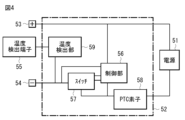
- FIG. 1 is a block diagram showing a configuration of an application example of a secondary battery.
- FIG. 2 is a cross-sectional view illustrating a configuration of a test secondary battery.
- 1 is a graph showing the correlation between the volume-based average particle size of a plurality of positive electrode active material particles and the weight-average molecular weight of a dispersant in terms of polyethylene oxide/polyethylene glycol.
- Positive electrode for secondary battery 1-1 Configuration 1-2. Operation 1-3. Manufacturing method 1-4. Action and effect 2. Secondary battery 2-1. Configuration 2-2. Operation 2-3. Manufacturing method 2-4. Action and effect 3. Modification 4. Uses of secondary battery
- Positive electrode for secondary batteries First, a positive electrode for a secondary battery (hereinafter simply referred to as a "positive electrode") according to an embodiment of the present technology will be described.
- the positive electrode described here is used in a secondary battery, which is an electrochemical device.
- the positive electrode may also be used in electrochemical devices other than secondary batteries. Examples of other electrochemical devices include primary batteries and capacitors.
- This positive electrode absorbs and releases electrode reactants when the electrochemical device is in operation (electrode reaction).
- the type of electrode reactant is not particularly limited, but specifically, it is a light metal such as an alkali metal or an alkaline earth metal.
- alkali metals include lithium, sodium, and potassium
- alkaline earth metals include beryllium, magnesium, and calcium.
- the electrode reactant is lithium.
- lithium is absorbed and released in an ionic state at the positive electrode during the electrode reaction.
- Fig. 1 shows a cross-sectional structure of a specific example of a positive electrode, a positive electrode 100.
- the positive electrode 100 includes a positive electrode current collector 100A and a positive electrode active material layer 100B.
- the positive electrode current collector 100A is a conductive support that supports the positive electrode active material layer 100B, and has a pair of surfaces (upper and lower surfaces) on which the positive electrode active material layer 100B is provided.
- the positive electrode current collector 100A contains a conductive material such as a metal material, and a specific example of the conductive material is aluminum.
- the positive electrode active material layer 100B is a layer that absorbs and releases lithium, and is provided on one surface (upper surface or lower surface) of the positive electrode current collector 100A. However, the positive electrode active material layer 100B may be provided on both surfaces (upper surface and lower surface) of the positive electrode current collector 100A.
- the positive electrode active material layer 100B contains a plurality of particulate positive electrode active materials (hereinafter referred to as "a plurality of positive electrode active material particles") that absorb and release lithium, and a dispersant. More specifically, the positive electrode active material layer 100B further contains a positive electrode binder and a positive electrode conductive agent.
- Each of the positive electrode active material particles contains one or more of the olivine-type iron-containing phosphate compounds, which, as described above, have an olivine-type crystal structure and contain iron as a constituent element.
- Each of the multiple positive electrode active material particles contains an olivine-type iron-containing phosphate compound because the crystal structure of the olivine-type iron-containing phosphate compound is strong and stable. This prevents oxygen from being released from the olivine-type iron-containing phosphate compound, so that a secondary battery using the positive electrode 100 can obtain a stable battery capacity and improve safety.
- the olivine-type iron-containing phosphate compound is a phosphate compound containing lithium and iron as constituent elements.
- the type of olivine-type iron-containing phosphate compound so long as it is a phosphate compound containing lithium and iron as constituent elements.
- the olivine-type iron-containing phosphate compound may further contain one or more metal elements (excluding iron) as constituent elements.
- the types of metal elements are not particularly limited, but specific examples include manganese, cobalt, nickel, titanium, chromium, vanadium, zinc, tin, tungsten, zirconium, magnesium, and aluminum.
- the sum of the iron content in the olivine-type iron-containing phosphate compound and the content of one or more metal elements in the olivine-type iron-containing phosphate compound is 100 molar parts.
- the iron content in the olivine-type iron-containing phosphate compound is not particularly limited, but is preferably 10 to 90 molar parts. This is because the electronic conductivity of the olivine-type iron-containing phosphate compound is sufficiently improved. This achieves both improved electronic conductivity of the multiple positive electrode active material particles and stabilization of the operating potential and battery capacity of a secondary battery using the positive electrode 100.
- the olivine-type iron-containing phosphate compound preferably contains one or more of the compounds represented by formula (10).
- y in formula (10) satisfies 0.1 ⁇ y ⁇ 0.9.
- olivine-type iron-containing phosphate compound examples include LiFePO 4 , LiFe 0.5 Mn 0.5 PO 4 , and LiFe 0.5 Co 0.5 PO 4 .
- the average particle size (volume-based average particle size) D of the multiple positive electrode active material particles is 0.6 ⁇ m or more.
- This average particle size D is the so-called median diameter D50.
- the average particle size D is 0.6 ⁇ m or more is that in the manufacturing process of the positive electrode 100 (preparation process of the positive electrode mixture slurry), a positive electrode mixture slurry having excellent dispersibility and excellent fluidity is prepared, and a positive electrode active material layer 100B having excellent flatness is formed.
- a positive electrode mixture slurry having excellent dispersibility and excellent fluidity is prepared, and a positive electrode active material layer 100B having excellent flatness is formed.
- the average particle size D is 23 ⁇ m or less. This is because a positive electrode mixture slurry having sufficiently excellent dispersibility and sufficiently excellent fluidity is prepared, and a positive electrode active material layer 100B having sufficiently excellent flatness is formed.
- the average particle size D is 4 ⁇ m to 15 ⁇ m or less. This is because the dispersibility and fluidity of the positive electrode mixture slurry are both improved, and the flatness of the positive electrode active material layer 100B is improved.
- a particle size measuring device is used to analyze multiple positive electrode active material particles, and the average particle size D is calculated.
- a laser diffraction/scattering type particle size distribution measuring device LA-960 manufactured by Horiba, Ltd. can be used.
- the positive electrode 100 is first introduced into an aqueous solvent to peel off the positive electrode active material layer 100B from the positive electrode current collector 100A.
- the type of aqueous solvent is not particularly limited, but specifically, it is pure water that can dissolve the positive electrode binder.
- the types of aqueous solvents described here are the same hereinafter.
- the positive electrode active material layer 100B is introduced into the aqueous solvent, and the aqueous solvent is stirred, and then filtered. As a result, the positive electrode binder and the dispersant are each dissolved and removed, and the solid content (multiple positive electrode active material particles and positive electrode conductive agent) is recovered.
- the solid content is added to the aqueous solvent, and the solid content in the aqueous solvent is centrifuged using a centrifuge. This separates the positive electrode active material particles from the positive electrode conductor, and the positive electrode active material particles are recovered. Finally, the positive electrode active material particles are analyzed using a particle size measuring device to measure the average particle size D.
- the positive electrode binder contains one or more of copolymers of acrylic acid ester and acrylonitrile, because decomposition of the positive electrode binder is suppressed even if the voltage of the secondary battery using the positive electrode 100 increases.
- the type of acrylic acid ester is not particularly limited, and may be one type or two or more types.
- specific examples of acrylic acid esters are methyl acrylate and ethyl acrylate, but other types are also acceptable.
- the amount of acrylonitrile copolymerized in the copolymer is not particularly limited, and may be set as desired.
- the amount of the positive electrode binder in the positive electrode active material layer 100B is not particularly limited, but is preferably 0.5% to 4% by weight. This is because it prevents the conductivity of the positive electrode 100 from decreasing.
- the content of the positive electrode binder in the positive electrode active material layer 100B is less than 0.5% by weight, the binding ability of the multiple positive electrode active material particles using the positive electrode binder will be insufficient. This may cause the positive electrode active material layer 100B to peel off from the positive electrode current collector 100A, resulting in a decrease in the conductivity of the positive electrode 100.
- the content of the positive electrode binder in the positive electrode active material layer 100B is greater than 4% by weight, the proportion of the low-conductivity component (positive electrode binder) contained in the positive electrode active material layer 100B increases, and the conductivity of the positive electrode 100 may decrease.
- the procedure for checking the content of the positive electrode binder in the positive electrode active material layer 100B is as follows.
- the positive electrode current collector 100A is peeled off from the positive electrode active material layer 100B, and the weight of the positive electrode active material layer 100B is measured.
- the positive electrode active material layer 100B is analyzed using thermogravimetric analysis (TGA) to calculate the weight of the positive electrode binder contained in the positive electrode active material layer 100B.
- TGA thermogravimetric analysis
- the thermal decomposition temperature of the positive electrode binder is about 300°C to 600°C
- the positive electrode active material layer 100B is heated at a heating rate of 1°C/min, and the weight of the positive electrode binder is calculated based on the weight reduction rate within the heating temperature range of about 300°C to 600°C.
- the content of the positive electrode binder in the positive electrode active material layer 100B is calculated based on the weight of the positive electrode active material layer 100B and the weight of the positive electrode binder.
- the positive electrode conductive agent contains one or more conductive materials such as a carbon material, a metal material, and a conductive polymer compound.
- the positive electrode conductive agent contains a carbon material. This is because the conductivity of the positive electrode active material layer 100B is sufficiently improved and the carbon material also functions as a positive electrode active material.
- Specific examples of carbon materials include graphite, carbon black, acetylene black, and ketjen black.
- the amount of the positive electrode conductive agent contained in the positive electrode active material layer 100B is not particularly limited, but is preferably 0.5% to 3% by weight. This is because the stability over time of the positive electrode mixture slurry is improved during the manufacturing process of the positive electrode 100, and the conductivity of the positive electrode 100 is sufficiently improved.
- the content of the positive electrode conductive agent in the positive electrode active material layer 100B is less than 0.5% by weight, the proportion of the conductive component (positive electrode binder) contained in the positive electrode active material layer 100B decreases, and the conductivity of the positive electrode 100 may decrease.
- the content of the positive electrode conductive agent in the positive electrode active material layer 100B is greater than 3% by weight, the fluidity of the positive electrode mixture slurry decreases during the manufacturing process of the positive electrode 100, and the stability of the positive electrode mixture slurry over time may decrease.
- the procedure for checking the content of the positive electrode conductive agent in the positive electrode active material layer 100B is as follows. The following describes the case where the positive electrode conductive agent is a carbon material.
- the positive electrode current collector 100A is peeled off from the positive electrode active material layer 100B, and then the weight of the positive electrode active material layer 100B is measured.
- the positive electrode active material layer 100B is immersed in an organic solvent to dissolve the positive electrode binder contained in the positive electrode active material layer 100B.
- organic solvent include one or more of N-methyl-2-pyrrolidone, dimethylformamide, and dimethylsulfoxide. The dissolved material is then filtered to recover the residue, which is then dried.
- the residue is immersed in an aqueous solvent to dissolve the dispersant contained in the residue.
- an aqueous solvent is water.
- the residue is then filtered to recover the residue, which is then dried.
- the residue is subjected to carbon analysis to calculate the weight of the carbon component (positive electrode conductive agent) contained in the residue.
- An analytical device for carbon analysis that can be used is the EMIA-920V2 carbon-sulfur analyzer (CS meter) manufactured by Horiba, Ltd.
- the content of the positive electrode conductive agent in the positive electrode active material layer 100B is calculated based on the weight of the positive electrode active material layer 100B and the weight of the positive electrode conductive agent.
- the dispersant is a material that improves the dispersibility of a plurality of positive electrode active material particles and the like when preparing a positive electrode mixture slurry in the manufacturing process of the positive electrode 100 .
- the dispersant contains one or more types of carboxymethyl cellulose salts. This is because it sufficiently improves the dispersibility and fluidity of the positive electrode mixture slurry during the manufacturing process of the positive electrode 100.
- carboxymethylcellulose salt is not particularly limited, but specific examples include carboxymethylcellulose alkali metal salts and carboxymethylcellulose alkaline earth metal salts. Specific examples of carboxymethylcellulose alkali metal salts include carboxymethylcellulose lithium, carboxymethylcellulose sodium, and carboxymethylcellulose potassium. Specific examples of carboxymethylcellulose alkaline earth metal salts include carboxymethylcellulose magnesium and carboxymethylcellulose calcium.
- the carboxymethylcellulose salt contains sodium carboxymethylcellulose, because this further improves the dispersibility and fluidity of the positive electrode mixture slurry.
- the weight average molecular weight M of the dispersant (weight average molecular weight calculated as polyethylene oxide (PEO)/polyethylene glycol (PEG)) satisfies the relationship expressed by formula (1).
- D is the average particle size D ( ⁇ m).
- the relationship shown in formula (1) will be referred to as the "optimum relationship.”
- M is the weight average molecular weight of the dispersant in terms of polyethylene oxide/polyethylene glycol.
- D is the volume-based average particle size of the multiple positive electrode active material particles.
- the weight average molecular weight M satisfies the optimum relationship because the weight average molecular weight M is optimized in relation to the average particle diameter D.
- the dispersant unintentionally functions as an agglomerant that cross-links and adsorbs the positive electrode active material particles to each other, and the aggregation of the positive electrode active material particles through the dispersant is suppressed.
- the positive electrode active material particles are sufficiently and uniformly dispersed, and a positive electrode mixture slurry having excellent dispersibility and excellent fluidity is prepared.
- the surface of the positive electrode active material layer 100B formed using the positive electrode mixture slurry is less prone to unevenness caused by coarse particles of the positive electrode active material, so that the positive electrode active material layer 100B has excellent flatness (coatability). As a result, a secondary battery with excellent battery characteristics is realized using the positive electrode 100.
- the dispersant is analyzed using a gel permeation chromatography (GPC) device to calculate the weight-average molecular weight M.
- GPC gel permeation chromatography
- the GPC device that can be used is the high-speed GPC device HLC-8320GPC manufactured by Tosoh Technosystems Corporation.
- the positive electrode current collector 100A is peeled off from the positive electrode active material layer 100B, and then the positive electrode active material layer 100B is immersed in an organic solvent to dissolve the positive electrode binder contained in the positive electrode active material layer 100B. Details regarding the organic solvent capable of dissolving the positive electrode binder are as described above. Next, the dissolved material is filtered to recover the residue, which is then dried.
- the residue is immersed in an aqueous solvent to dissolve the dispersant contained in the residue. Details regarding the aqueous solvent capable of dissolving the dispersant are as described above.
- the dissolved material is then filtered to recover the filtrate, which is then dried to recover the dispersant.
- the type of aqueous solvent is not particularly limited, but specifically, it is pure water, etc.
- a sample solution for analysis is prepared.
- the weight average molecular weight M is measured by analyzing the sample solution using a GPC device.
- the weight average molecular weight M is measured using a calibration curve (a cubic approximation curve using standard PEO/PEG from Agilent Technologies). As a result, the value of the weight average molecular weight M is converted into a PEO/PEG value.
- the amount of dispersant contained in the positive electrode active material layer 100B is not particularly limited, but is preferably 0.6% to 2% by weight. This is because the stability over time of the positive electrode mixture slurry is improved during the manufacturing process of the positive electrode 100, and the physical durability of the positive electrode active material layer 100B formed using the positive electrode mixture slurry is improved.
- the content of the dispersant in the positive electrode active material layer 100B is less than 0.6% by weight, the fluidity of the positive electrode mixture slurry decreases during the manufacturing process of the positive electrode 100, and the stability over time of the positive electrode mixture slurry may decrease.
- the positive electrode active material layer 100B formed using the positive electrode mixture slurry becomes excessively hard, and the physical durability of the positive electrode active material layer 100B may decrease. In this case, the positive electrode active material layer 100B may crack, and may also fall off the positive electrode current collector 100A.
- the procedure for checking the content of dispersant in the positive electrode active material layer 100B is as follows.
- the positive electrode current collector 100A is peeled off from the positive electrode active material layer 100B, and the weight of the positive electrode active material layer 100B is measured.
- the positive electrode active material layer 100B is analyzed using thermogravimetric analysis in a nitrogen atmosphere to calculate the weight of the dispersant contained in the positive electrode active material layer 100B.
- the thermal decomposition temperature of the dispersant is about 250°C
- the positive electrode active material layer 100B is heated at a heating rate of 1°C/min, and the weight of the dispersant is calculated based on the weight reduction rate within the heating temperature range of room temperature to about 250°C.
- the content of the dispersant in the positive electrode active material layer 100B is calculated based on the weight of the positive electrode active material layer 100B and the weight of the dispersant.
- the positive electrode 100 is manufactured by the procedure of one example of which is described below.
- a positive electrode active material particle containing an olivine-type iron-containing phosphate compound, a positive electrode binder, a positive electrode conductive agent, and a dispersant containing a carboxymethyl cellulose salt are mixed together to form a positive electrode mixture.
- the positive electrode mixture is added to the aqueous solvent to prepare a paste-like positive electrode mixture slurry.
- the type of aqueous solvent is not particularly limited, but specifically, as described above, it is pure water, etc.
- the positive electrode mixture slurry is applied to one side of the positive electrode current collector 100A to form the positive electrode active material layer 100B.
- the positive electrode active material layer 100B may be compression molded using a roll press or the like. In this case, the positive electrode active material layer 21B may be heated, or the compression molding may be repeated multiple times.
- the positive electrode active material layer 100B is formed on both sides of the positive electrode current collector 100A, completing the positive electrode 100.
- the positive electrode 100 contains a plurality of positive electrode active material particles (olivine-type iron-containing phosphate compound) and a dispersant (carboxymethyl cellulose salt), the average particle size D of the plurality of positive electrode active material particles is 0.6 ⁇ m or more, and the weight-average molecular weight M of the dispersant satisfies an appropriate relationship.
- positive electrode active material particles olivine-type iron-containing phosphate compound
- dispersant carboxymethyl cellulose salt
- the dispersant In the manufacturing process of the positive electrode 100 (preparation process of the positive electrode mixture slurry), the dispersant unintentionally functions as an agglomerant that cross-links and adsorbs the positive electrode active material particles to each other, and this prevents the positive electrode active material particles from agglomerating via the dispersant. This allows the positive electrode active material particles to be sufficiently and uniformly dispersed, thereby preparing a positive electrode mixture slurry with excellent dispersibility and excellent fluidity.
- the surface of the positive electrode active material layer 100B formed using the positive electrode mixture slurry is less likely to have irregularities due to coarse particles of the positive electrode active material, so that the positive electrode active material layer 100B has excellent flatness (coatability).
- the positive electrode active material layer 100B is formed well and stably using the positive electrode mixture slurry, so that a secondary battery with excellent battery characteristics can be realized using the positive electrode 100.
- the average particle size D is 23 ⁇ m, a positive electrode mixture slurry having sufficiently excellent dispersibility and sufficiently excellent fluidity is prepared, and a positive electrode active material layer 100B having sufficiently excellent flatness is formed, so that a greater effect can be obtained.
- the average particle size D is 4 ⁇ m to 15 ⁇ m, the dispersibility and fluidity of the positive electrode mixture slurry are both improved, and the flatness of the positive electrode active material layer 100B is improved, so that a high effect can be obtained.
- the content of the dispersant in the positive electrode active material layer 100B is 0.6% by weight to 2% by weight, the stability over time of the positive electrode mixture slurry in the manufacturing process of the positive electrode 100 is improved, and the physical durability of the positive electrode active material layer 100B formed using the positive electrode mixture slurry is also improved, so that a greater effect can be obtained.
- the olivine-type iron-containing phosphate compound further contains one or more metal elements (excluding iron) as constituent elements and the iron content in the olivine-type iron-containing phosphate compound is 10 to 90 parts by mole, the electronic conductivity of the olivine-type iron-containing phosphate compound is sufficiently improved, and a greater effect can be obtained.
- the carboxymethylcellulose salt contains sodium carboxymethylcellulose, the dispersibility and fluidity of the positive electrode mixture slurry are further improved, resulting in even greater effects.
- the positive electrode active material layer 100B further contains a positive electrode binder (a copolymer of acrylic acid ester and acrylonitrile) and the content of the positive electrode binder in the positive electrode active material layer 100B is 0.5% by weight to 4% by weight, the decrease in the conductivity of the positive electrode 100 is suppressed, and a greater effect can be obtained.
- a positive electrode binder a copolymer of acrylic acid ester and acrylonitrile
- the positive electrode active material layer 100B further contains a positive electrode conductive agent (carbon material) and the content of the positive electrode conductive agent in the positive electrode active material layer 100B is 0.5% by weight to 3% by weight, the stability over time of the positive electrode mixture slurry is improved in the manufacturing process of the positive electrode 100, and the conductivity of the positive electrode 100 is sufficiently improved, so that a higher effect can be obtained.
- a positive electrode conductive agent carbon material
- the secondary battery described here is a secondary battery that obtains battery capacity by utilizing the absorption and release of an electrode reactant, and is equipped with a positive electrode, a negative electrode, and an electrolyte.
- the electrode reactant is lithium.
- a secondary battery that obtains battery capacity by utilizing the absorption and release of lithium is a so-called lithium-ion secondary battery. In this lithium-ion secondary battery, lithium is absorbed and released in an ionic state.
- the charge capacity of the negative electrode is preferably greater than the discharge capacity of the positive electrode.
- the electrochemical capacity per unit area of the negative electrode is preferably greater than the electrochemical capacity per unit area of the positive electrode. This is to prevent lithium from being deposited on the surface of the negative electrode during charging.
- FIG. 2 shows a cross-sectional structure of a secondary battery
- FIG. 3 shows a cross-sectional structure of a battery element 20 shown in FIG.
- this secondary battery includes a battery can 11, a pair of insulating plates 12, 13, a battery element 20, a positive electrode lead 25, and a negative electrode lead 26.
- the secondary battery described here is a cylindrical secondary battery in which the battery element 20 is housed inside the cylindrical battery can 11.
- the battery can 11 is a storage member for storing the battery element 20 and the like.
- the battery can 11 has an open end and a closed other end, and thus has a hollow structure.
- the battery can 11 contains one or more types of metal materials such as iron, aluminum, iron alloys, and aluminum alloys.
- the surface of the battery can 11 may be plated with a metal material such as nickel.
- a battery lid 14, a safety valve mechanism 15, and a thermosensitive resistor (PTC element) 16 are crimped via a gasket 17 to the open end of the battery can 11. This causes the battery can 11 to be sealed by the battery lid 14.
- the battery lid 14 contains the same material as the material from which the battery can 11 is formed.
- the safety valve mechanism 15 and the PTC element 16 are provided on the inside of the battery lid 14, and the safety valve mechanism 15 is electrically connected to the battery lid 14 via the PTC element 16.
- the gasket 17 contains an insulating material, and the surface of the gasket 17 may be coated with asphalt or the like.
- the safety valve mechanism 15 When the internal pressure of the battery can 11 reaches a certain level due to an internal short circuit, external heating, or the like, the safety valve mechanism 15 reverses the disk plate 15A, cutting off the electrical connection between the battery cover 14 and the battery element 20. To prevent abnormal heat generation due to a large current, the electrical resistance of the PTC element 16 increases with increasing temperature.
- the insulating plates 12 and 13 are disposed so as to face each other with the battery element 20 interposed therebetween. As a result, the battery element 20 is sandwiched between the insulating plates 12 and 13.
- the battery element 20 is a power generating element including a positive electrode 21, a negative electrode 22, a separator 23, and an electrolyte (not shown).
- This battery element 20 is a so-called wound electrode body. That is, the positive electrode 21 and the negative electrode 22 are stacked on top of each other with a separator 23 interposed therebetween, and are wound while facing each other with the separator 23 interposed therebetween.
- a center pin 24 is inserted into a space 20S provided at the winding center of the battery element 20. However, the center pin 24 may be omitted.
- the positive electrode 21 has a configuration similar to that of the positive electrode 100 .
- the positive electrode 21 includes a positive electrode collector 21A and a positive electrode active material layer 21B.
- the configuration of the positive electrode collector 21A is similar to that of the positive electrode collector 100A, and the configuration of the positive electrode active material layer 21B is similar to that of the positive electrode active material layer 100B.
- the positive electrode active material layer 21B is provided on both sides of the positive electrode collector 21A.
- the negative electrode 22 includes a negative electrode current collector 22A and a negative electrode active material layer 22B.
- the negative electrode current collector 22A has a pair of surfaces on which the negative electrode active material layer 22B is provided.
- This negative electrode current collector 22A contains a conductive material such as a metal material, and a specific example of the conductive material is copper.
- the negative electrode active material layer 22B contains one or more types of negative electrode active materials that absorb and release lithium. However, the negative electrode active material layer 22B may further contain one or more types of other materials such as a negative electrode binder and a negative electrode conductor.
- the method of forming the negative electrode active material layer 22B is not particularly limited, but specifically includes one or more types of a coating method, a gas phase method, a liquid phase method, a thermal spraying method, and a baking method (sintering method).
- the negative electrode active material layer 22B is provided on both sides of the negative electrode current collector 22A, so the negative electrode 22 includes two negative electrode active material layers 22B.
- the negative electrode active material layer 22B is provided on only one side of the negative electrode current collector 22A on the side where the negative electrode 22 faces the positive electrode 21, the negative electrode 22 may include only one negative electrode active material layer 22B.
- the type of negative electrode active material is not particularly limited, but specific examples include carbon materials and metal-based materials, because they provide high energy density.
- carbon materials include graphitizable carbon, non-graphitizable carbon, and graphite (natural graphite and artificial graphite).
- the metal-based material is a material that contains one or more of metal elements and metalloid elements that can form an alloy with lithium as a constituent element, and specific examples of the metal elements and metalloid elements are silicon and tin.
- the metal-based material may be a simple substance, an alloy, a compound, a mixture of two or more of them, or a material containing two or more phases of them. However, since the simple substance may contain any amount of impurities, the purity of the simple substance is not necessarily limited to 100%.
- Specific examples of the metal-based material are TiSi 2 and SiO x (0 ⁇ x ⁇ 2, or 0.2 ⁇ x ⁇ 1.4).
- the negative electrode binder contains one or more of the following materials: synthetic rubber and polymeric compounds.
- synthetic rubber include styrene-butadiene rubber, fluororubber, and ethylene-propylene-diene.
- polymeric compounds include polyvinylidene fluoride, polyimide, and carboxymethyl cellulose.
- the negative electrode conductive agent contains one or more conductive materials such as carbon materials, metal materials, and conductive polymer compounds.
- conductive materials such as carbon materials, metal materials, and conductive polymer compounds.
- Specific examples of carbon materials include graphite, carbon black, acetylene black, and ketjen black.
- the separator 23 is an insulating porous film interposed between the positive electrode 21 and the negative electrode 22, and allows lithium ions to pass through while preventing contact (short circuit) between the positive electrode 21 and the negative electrode 22.
- the separator 23 contains a polymer compound such as polyethylene.
- the electrolytic solution is a liquid electrolyte, and is impregnated into each of the positive electrode 21, the negative electrode 22, and the separator 23.
- the electrolytic solution contains a solvent and an electrolyte salt.
- the solvent contains one or more types of non-aqueous solvents (organic solvents), and the electrolyte containing the non-aqueous solvent is a so-called non-aqueous electrolyte.
- the non-aqueous solvent is an ester or ether, more specifically a carbonate ester compound, a carboxylate ester compound, or a lactone compound. This is because it improves the dissociation of the electrolyte salt and the mobility of the ions.
- Carbonate compounds include cyclic carbonates and chain carbonates. Specific examples of cyclic carbonates include ethylene carbonate and propylene carbonate, while specific examples of chain carbonates include dimethyl carbonate, diethyl carbonate, and ethyl methyl carbonate.
- Carboxylic acid ester compounds include chain carboxylates.
- chain carboxylates include ethyl acetate, ethyl propionate, propyl propionate, and ethyl trimethylacetate.
- Lactone compounds include lactones. Specific examples of lactones include gamma-butyrolactone and gamma-valerolactone.
- the ethers may be 1,2-dimethoxyethane, tetrahydrofuran, 1,3-dioxolane, 1,4-dioxane, etc.
- Non-aqueous solvents include unsaturated cyclic carbonates, fluorinated cyclic carbonates, sulfonates, phosphates, acid anhydrides, nitrile compounds, and isocyanate compounds. This is because they improve the electrochemical stability of the electrolyte.
- unsaturated cyclic carbonates include vinylene carbonate, vinylethylene carbonate, and methyleneethylene carbonate.
- fluorinated cyclic carbonates include monofluoroethylene carbonate and difluoroethylene carbonate.
- sulfonic acid esters include propane sultone and propene sultone.
- phosphate esters include trimethyl phosphate and triethyl phosphate.
- acid anhydrides include succinic anhydride, 1,2-ethanedisulfonic anhydride, and 2-sulfobenzoic anhydride.
- nitrile compounds include succinonitrile.
- isocyanate compounds include hexamethylene diisocyanate.
- the electrolyte salt contains one or more types of light metal salts such as lithium salts.
- lithium salts include lithium hexafluorophosphate ( LiPF6 ), lithium tetrafluoroborate ( LiBF4 ), lithium trifluoromethanesulfonate ( LiCF3SO3 ), lithium bis(fluorosulfonyl)imide (LiN( FSO2 ) 2 ), lithium bis(trifluoromethanesulfonyl)imide (LiN( CF3SO2 ) 2 ), lithium tris(trifluoromethanesulfonyl)methide (LiC( CF3SO2 ) 3 ), lithium bis( oxalato )borate (LiB( C2O4 ) 2 ), lithium monofluorophosphate ( Li2PFO3 ), and lithium difluorophosphate ( LiPF2O2 ). This is because a high battery capacity can be obtained.
- LiPF6 lithium hexafluorophosphate
- LiBF4 lithium tetrafluoroborate
- the amount of electrolyte salt contained is not particularly limited, but is typically 0.3 mol/kg to 3.0 mol/kg relative to the solvent. This is because high ionic conductivity is obtained.
- the positive electrode lead 25 is connected to the positive electrode current collector 21A of the positive electrode 21, and contains a conductive material such as aluminum.
- the positive electrode lead 25 is electrically connected to the battery lid 14 via the safety valve mechanism 15.
- the negative electrode lead 26 is connected to the negative electrode current collector 22A of the negative electrode 22 and contains a conductive material such as nickel. This negative electrode lead 26 is electrically connected to the battery can 11.
- a secondary battery operates as follows when charging and discharging.
- lithium When charging, lithium is released from the positive electrode 21 in the battery element 20 and is absorbed in the negative electrode 22 via the electrolyte.
- lithium When discharging, lithium is released from the negative electrode 22 in the battery element 20 and is absorbed in the positive electrode 21 via the electrolyte.
- lithium is absorbed and released in an ionic state.
- the positive electrode 21 is produced by forming the positive electrode active material layers 21B on both sides of the positive electrode current collector 21A using a procedure similar to that for producing the positive electrode 100 described above.
- the negative electrode 22 is formed by the same procedure as the procedure for producing the positive electrode 21 described above. Specifically, first, a mixture (negative electrode mixture) in which a negative electrode active material, a negative electrode binder, and a negative electrode conductive agent are mixed together is poured into a solvent to prepare a paste-like negative electrode mixture slurry. Next, the negative electrode mixture slurry is applied to both sides of the negative electrode current collector 22A to form the negative electrode active material layer 22B. After this, the negative electrode active material layer 22B may be compression molded. As a result, the negative electrode active material layer 22B is formed on both sides of the negative electrode current collector 22A, and the negative electrode 22 is produced.
- electrolyte solution An electrolyte salt is added to a solvent, whereby the electrolyte salt is dispersed or dissolved in the solvent, and an electrolyte solution is prepared.
- a positive electrode lead 25 is connected to the positive electrode collector 21A of the positive electrode 21 by a joining method such as welding, and a negative electrode lead 26 is connected to the negative electrode collector 22A of the negative electrode 22 by a joining method such as welding.
- the positive electrode 21 and the negative electrode 22 are stacked on each other via the separator 23, and then the positive electrode 21, the negative electrode 22, and the separator 23 are wound to prepare a wound body (not shown) having a space 20S.
- This wound body has a configuration similar to that of the battery element 20, except that the positive electrode 21, the negative electrode 22, and the separator 23 are not impregnated with an electrolyte.
- a center pin 24 is inserted into the space 20S of the wound body.
- the positive electrode lead 25 is connected to the safety valve mechanism 15 using a joining method such as welding
- the negative electrode lead 26 is connected to the battery can 11 using a joining method such as welding.
- an electrolyte is injected into the battery can 11, thereby impregnating the wound body with the electrolyte.
- the positive electrode 21, the negative electrode 22, and the separator 23 are each impregnated with the electrolyte, and the battery element 20 is produced.
- the battery lid 14, safety valve mechanism 15, and PTC element 16 are housed inside the battery can 11, and then the battery can 11 is crimped via the gasket 17. This fixes the battery lid 14, safety valve mechanism 15, and PTC element 16 to the battery can 11, and the battery element 20 is sealed inside the battery can 11, thus assembling a secondary battery.
- the assembled secondary battery is charged and discharged.
- Various conditions such as the environmental temperature, the number of charge/discharge cycles (number of cycles), and the charge/discharge conditions can be set arbitrarily.
- a coating is formed on the surface of each of the positive electrode 21 and the negative electrode 22, and the state of the battery element 20 is electrochemically stabilized.
- the secondary battery is completed.
- the positive electrode 21 has a configuration similar to that of the positive electrode 100. Therefore, for the reasons described above, the positive electrode active material layer 21B is favorably and stably formed using the positive electrode mixture slurry, and therefore excellent battery characteristics can be obtained.
- the secondary battery is a lithium-ion secondary battery
- sufficient battery capacity can be stably obtained by utilizing the absorption and release of lithium, resulting in even greater effects.
- the other functions and effects of the secondary battery are the same as those of the positive electrode 100.
- a porous membrane separator 23 was used. However, although not specifically shown here, a laminated separator including a polymer compound layer may also be used.
- the laminated separator includes a porous membrane having a pair of surfaces, and a polymer compound layer provided on one or both surfaces of the porous membrane. This is because the adhesion of the separator to each of the positive electrode 21 and the negative electrode 22 is improved, thereby suppressing misalignment of the battery element 20 (misalignment of the positive electrode 21, the negative electrode 22, and the separator 23). This prevents the secondary battery from swelling even if a decomposition reaction of the electrolyte occurs.
- the polymer compound layer includes a polymer compound such as polyvinylidene fluoride. This is because polyvinylidene fluoride and the like have excellent physical strength and are electrochemically stable.
- one or both of the porous film and the polymer compound layer may contain a plurality of insulating particles.
- the plurality of insulating particles contain one or more types of insulating materials such as inorganic materials and resin materials.
- inorganic materials include aluminum oxide, aluminum nitride, boehmite, silicon oxide, titanium oxide, magnesium oxide, and zirconium oxide.
- resin materials include acrylic resin and styrene resin.
- a precursor solution containing a polymer compound and a solvent is prepared, and then the precursor solution is applied to one or both sides of a porous film.
- multiple insulating particles may be added to the precursor solution as necessary.
- the positive electrode 21 and the negative electrode 22 are stacked on top of each other with the separator 23 and the electrolyte layer in between, and the positive electrode 21, the negative electrode 22, the separator 23, and the electrolyte layer are wound.
- the electrolyte layer is interposed between the positive electrode 21 and the separator 23, and also between the negative electrode 22 and the separator 23.
- the electrolyte layer contains a polymer compound as well as an electrolyte solution, and the electrolyte solution is held by the polymer compound. This is because leakage of the electrolyte solution is prevented.
- the composition of the electrolyte solution is as described above.
- the polymer compound contains polyvinylidene fluoride and the like.
- the use (application example) of the secondary battery is not particularly limited.
- the secondary battery used as a power source may be a main power source or an auxiliary power source in electronic devices, electric vehicles, etc.
- the main power source is a power source that is used preferentially regardless of the presence or absence of other power sources.
- the auxiliary power source may be a power source used in place of the main power source, or a power source that is switched from the main power source.
- secondary batteries are as follows: Electronic devices such as video cameras, digital still cameras, mobile phones, laptop computers, headphone stereos, portable radios, and portable information terminals. Storage devices such as backup power sources and memory cards. Power tools such as electric drills and power saws. Battery packs installed in electronic devices. Medical electronic devices such as pacemakers and hearing aids. Electric vehicles such as electric cars (including hybrid cars). Power storage systems such as home or industrial battery systems that store power in preparation for emergencies. In these applications, one secondary battery may be used, or multiple secondary batteries may be used.
- the battery pack may use a single cell or a battery pack.
- the electric vehicle is a vehicle that runs on a secondary battery as a driving power source, and may be a hybrid vehicle that also has a driving source other than the secondary battery.
- a home power storage system it is possible to use home electrical appliances, etc., by using the power stored in the secondary battery, which is a power storage source.
- FIG. 4 shows the block diagram of a battery pack.
- the battery pack described here is a battery pack (a so-called soft pack) that uses one secondary battery, and is installed in electronic devices such as smartphones.
- this battery pack includes a power source 51 and a circuit board 52.
- This circuit board 52 is connected to the power source 51 and includes a positive terminal 53, a negative terminal 54, and a temperature detection terminal 55.
- the power source 51 includes one secondary battery.
- the positive electrode lead is connected to the positive electrode terminal 53
- the negative electrode lead is connected to the negative electrode terminal 54.
- This power source 51 can be connected to the outside via the positive electrode terminal 53 and the negative electrode terminal 54, and therefore can be charged and discharged.
- the circuit board 52 includes a control unit 56, a switch 57, a PTC element 58, and a temperature detection unit 59. However, the PTC element 58 may be omitted.
- the control unit 56 includes a central processing unit (CPU) and memory, and controls the operation of the entire battery pack. This control unit 56 detects and controls the usage state of the power source 51 as necessary.
- CPU central processing unit
- the control unit 56 turns off the switch 57 to prevent charging current from flowing through the current path of the power source 51.
- the overcharge detection voltage is not particularly limited, but is specifically 4.20V ⁇ 0.05V.
- the overdischarge detection voltage is not particularly limited, but is specifically 2.40V ⁇ 0.1V.
- Switch 57 includes a charge control switch, a discharge control switch, a charge diode, and a discharge diode, and switches between the presence and absence of a connection between power source 51 and an external device in response to an instruction from control unit 56.
- This switch 57 includes a field effect transistor (MOSFET) that uses a metal oxide semiconductor, and the charge and discharge current is detected based on the ON resistance of switch 57.
- MOSFET field effect transistor
- the temperature detection unit 59 includes a temperature detection element such as a thermistor. This temperature detection unit 59 measures the temperature of the power supply 51 using the temperature detection terminal 55, and outputs the temperature measurement result to the control unit 56. The temperature measurement result measured by the temperature detection unit 59 is used when the control unit 56 performs charge/discharge control in the event of abnormal heat generation, and when the control unit 56 performs correction processing when calculating the remaining capacity.
- FIG. 5 shows a cross-sectional structure of a test secondary battery, which is a so-called coin-type secondary battery (lithium ion secondary battery).
- this secondary battery includes a test electrode 61, a counter electrode 62, a separator 63, an exterior cup 64, an exterior can 65, a gasket 66, and an electrolyte (not shown).
- the test electrode 61 is housed in an exterior cup 64, and the counter electrode 62 is housed in an exterior can 65.
- the test electrode 61 and the counter electrode 62 are stacked together via a separator 63, and the test electrode 61, the counter electrode 62, and the separator 63 are each impregnated with an electrolyte.
- the exterior cup 64 and the exterior can 65 are crimped together via a gasket 66, so that the test electrode 61, the counter electrode 62, and the separator 63 are sealed by the exterior cup 64 and the exterior can 65.
- the coin-type secondary battery shown in Figure 5 was fabricated using the procedure described below.
- a positive electrode active material LiFePO 4 , which is an olivine-type iron-containing phosphate compound
- a positive electrode mixture was prepared by mixing 94 parts by mass of a positive electrode binder (a copolymer of acrylic acid ester and acrylonitrile (CAA), the copolymerization amount of acrylonitrile is 30% by weight), 3 parts by mass of a positive electrode conductive agent (carbon black (CB)), and 2 parts by mass of a dispersant (carboxymethylcellulose sodium (CMCNa) which is a carboxymethylcellulose salt).
- the positive electrode mixture was put into a solvent (pure water which is an aqueous solvent), and the solvent was stirred to prepare a paste-like positive electrode mixture slurry.
- the cathode mixture slurry was applied (amount applied: 22 mg/ cm2 ) to one side of the cathode current collector 21A (a strip-shaped aluminum foil having a thickness of 12 ⁇ m) using a coating device, and the cathode mixture slurry was then dried to form the cathode active material layer 21B.
- the cathode active material layer 21B was compression molded (volume density: 2.1 g/ cm3 ) using a roll press, and the cathode current collector 21A on which the cathode active material layer 21B was formed was punched out into a disk shape (diameter: 16.5 mm). In this way, the test electrode 61 was produced.
- An electrolyte salt lithium hexafluorophosphate ( LiPF6 )
- a solvent ethylene carbonate, which is a cyclic carbonate ester, and diethyl carbonate, which is a chain carbonate ester
- the content of the electrolyte salt in the electrolyte solution was 1 mol/kg relative to the solvent. In this way, the electrolyte solution was prepared.
- test electrode 61 was accommodated in the exterior cup 64, and the counter electrode 62 was accommodated in the exterior can 65.
- the test electrode 61 accommodated in the exterior cup 64 and the counter electrode 62 accommodated in the exterior can 65 were stacked together via a separator 63 (a microporous polyethylene film with a thickness of 20 ⁇ m and a diameter of 17.5 mm) impregnated with an electrolyte.
- the exterior cup 64 and the exterior can 65 were crimped together via a gasket 66.
- the test electrode 61 and the counter electrode 62 were enclosed in the exterior cup 64 and the exterior can 65, and thus a secondary battery was assembled.
- the positive electrode mixture slurry was squeegeeed on the surface of a grind gauge (a grain size measuring instrument (grind gauge) single groove grind meter manufactured by TP Giken Co., Ltd.), and the state of the positive electrode mixture slurry was visually observed to judge the coatability of the positive electrode mixture slurry. Specifically, a case where no linear scratches were generated in an area where the scale was 50 ⁇ m or more was judged as "A”, and a case where linear scratches were generated in an area where the scale was 50 ⁇ m or more was judged as "B".
- the fluidity of the positive electrode mixture slurry was determined by measuring the B-type viscosity of the positive electrode mixture slurry using a B-type viscometer (B-type viscometer TV-22 manufactured by Toki Sangyo Co., Ltd.). Specifically, the case where the change in the B-type viscosity of the positive electrode mixture slurry was less than 3 Pa ⁇ s was determined as "A", and the case where the change in the B-type viscosity of the positive electrode mixture slurry was 3 Pa ⁇ s or more was determined as "B".
- the battery was charged at a constant current of 0.2 C until the voltage reached 4.2 V, and then charged at a constant voltage of 4.2 V until the current reached 0.05 C.
- the battery was discharged at a constant current of 0.2 C until the voltage reached 3.0 V.
- 0.2 C is the current value at which the battery capacity (theoretical capacity) is fully discharged in 5 hours
- 0.05 C is the current value at which the battery capacity is fully discharged in 20 hours.
- the secondary battery was charged and discharged in the same environment to measure the discharge capacity (discharge capacity of the second cycle).
- the charge and discharge conditions were the same as those of the first cycle, except that the current during discharge was changed to 2C.
- 2C is the current value at which the battery capacity is fully discharged in 0.5 hours.
- Capacity retention rate (%) (Discharge capacity at 2nd cycle/Discharge capacity at 1st cycle) x 100.
- Fig. 6 shows the correlation between the average particle diameter D ( ⁇ m) and the weight average molecular weight M.
- D average particle diameter
- Fig. 6 shows the case where all three types of judgment results (coatability, fluidity, and capacity retention rate) were A is indicated by “ ⁇ "
- ⁇ the case where two of the three types of judgment results were A is indicated by " ⁇ ”
- X the case where all three types of judgment results were B is indicated by "X”.
- Examples 1 to 15 when two conditions were met (Examples 1 to 15), good results were obtained in two or more of the three types of evaluation results when the average particle size D was 23 ⁇ m or less. In this case, good results were obtained in all three types of evaluation results when the average particle size D was 4 ⁇ m to 15 ⁇ m (Examples 3 to 11).
- Examples 16 to 20> As shown in Table 3, secondary batteries were produced in the same manner as in Example 7, except that the content (wt %) of the dispersant in the positive electrode active material layer 21B was changed. Then, the physical properties of the positive electrode mixture slurry and the battery characteristics of the secondary batteries were evaluated.
- the dispersant content in the positive electrode active material layer 21B was examined and it was confirmed that the dispersant content in the positive electrode active material layer 21B was as shown in Table 3.
- Example 21 to 26 As shown in Table 4, secondary batteries were produced in the same manner as in Example 7, except that the content (wt %) of the positive electrode binder in the positive electrode active material layer 21B was changed. Then, the physical properties of the positive electrode mixture slurry and the battery characteristics of the secondary batteries were evaluated.
- the content of the positive electrode binder in the positive electrode active material layer 21B was checked, and it was confirmed that the content of the positive electrode binder in the positive electrode active material layer 21B was as shown in Table 4.
- Examples 27 to 31> As shown in Table 5, secondary batteries were produced in the same manner as in Example 7, except that the content (wt %) of the positive electrode conductive agent in the positive electrode active material layer 21B was changed. Then, the physical properties of the positive electrode mixture slurry and the battery characteristics of the secondary batteries were evaluated.
- the content of the positive electrode conductive agent in the positive electrode active material layer 21B was examined, and it was confirmed that the content of the positive electrode conductive agent in the positive electrode active material layer 21B was as shown in Table 5.
- the positive electrode active material layer 21B contains a plurality of positive electrode active material particles (olivine-type iron-containing phosphate compound) and a dispersant (carboxymethyl cellulose salt), the average particle diameter D of the plurality of positive electrode active material particles is 0.6 ⁇ m or more, and the weight-average molecular weight M of the dispersant satisfies the appropriate relationship, excellent coating properties and excellent flowability were obtained, and an excellent capacity retention rate was also obtained. Therefore, the coating properties and flow properties of the positive electrode mixture slurry were improved, and the charge and discharge properties of the secondary battery were also improved, resulting in excellent battery properties.
- the coating properties and flow properties of the positive electrode mixture slurry were improved, and the charge and discharge properties of the secondary battery were also improved, resulting in excellent battery properties.
- the battery structure of the secondary battery has been described as cylindrical and coin type.
- the battery structure of the secondary battery is not particularly limited, and may be a laminate film type, a square type, a button type, etc.
- the battery element has been described as having a wound structure.
- the structure of the battery element is not particularly limited, and may be a stacked type or a zigzag type.
- the positive and negative electrodes are stacked on top of each other, and in the zigzag type, the positive and negative electrodes are folded in a zigzag pattern.
- the electrode reactant is described as being lithium, the electrode reactant is not particularly limited. Specifically, as described above, the electrode reactant may be other alkali metals such as sodium and potassium, or alkaline earth metals such as beryllium, magnesium and calcium. In addition, the electrode reactant may be other light metals such as aluminum.
- the present technology can also be configured as follows. ⁇ 1> a positive electrode including a positive electrode active material layer; A negative electrode; An electrolyte;
- the positive electrode active material layer is A plurality of positive electrode active material particles;
- Each of the plurality of positive electrode active material particles contains an olivine-type iron-containing phosphate compound,
- the dispersant comprises a carboxymethyl cellulose salt,
- the volume-based average particle size of the plurality of positive electrode active material particles is 0.6 ⁇ m or more,
- the weight average molecular weight of the dispersant in terms of polyethylene oxide/polyethylene glycol satisfies the relationship represented by formula (1).
- Secondary battery M ⁇ 135106 ⁇ D+548936 ...
- M is the weight average molecular weight of the dispersant in terms of polyethylene oxide/polyethylene glycol.
- D is the volume-based average particle size of the multiple positive electrode active material particles.
- the volume-based average particle size of the plurality of positive electrode active material particles is 23 ⁇ m or less.
- ⁇ 3> The volume-based average particle size of the plurality of positive electrode active material particles is 4 ⁇ m or more and 15 ⁇ m or less.
- ⁇ 4> The content of the dispersant in the positive electrode active material layer is 0.6% by weight or more and 2% by weight or less. ⁇ 1> to ⁇ 3>.
- the olivine-type iron-containing phosphate compound further contains one or more transition metal elements (excluding iron) as constituent elements, the content of the iron is 10 parts by mol or more and 90 parts by mol or less, when the sum of the contents of the iron and the one or more transition metal elements in the olivine-type iron-containing phosphate compound is 100 parts by mol;
- the carboxymethylcellulose salt includes sodium carboxymethylcellulose.
- the positive electrode active material layer further contains a positive electrode binder,
- the positive electrode binder contains a copolymer of an acrylic acid ester and an acrylonitrile, The content of the positive electrode binder in the positive electrode active material layer is 0.5% by weight or more and 4% by weight or less.
- the positive electrode active material layer further contains a positive electrode conductive agent,
- the positive electrode conductive agent includes a carbon material, The content of the positive electrode conductive agent in the positive electrode active material layer is 0.5% by weight or more and 3% by weight or less.
- a positive electrode active material layer is included, The positive electrode active material layer is A plurality of positive electrode active material particles; A dispersant; Each of the plurality of positive electrode active material particles contains an olivine-type iron-containing phosphate compound, The dispersant comprises a carboxymethyl cellulose salt, The volume-based average particle size of the plurality of positive electrode active material particles is 0.6 ⁇ m or more, The weight average molecular weight of the dispersant in terms of polyethylene oxide/polyethylene glycol satisfies the relationship represented by formula (1).
Landscapes
- Chemical & Material Sciences (AREA)
- Chemical Kinetics & Catalysis (AREA)
- Electrochemistry (AREA)
- General Chemical & Material Sciences (AREA)
- Engineering & Computer Science (AREA)
- Inorganic Chemistry (AREA)
- Manufacturing & Machinery (AREA)
- Composite Materials (AREA)
- Materials Engineering (AREA)
- Crystallography & Structural Chemistry (AREA)
- Physics & Mathematics (AREA)
- Condensed Matter Physics & Semiconductors (AREA)
- General Physics & Mathematics (AREA)
- Battery Electrode And Active Subsutance (AREA)
Priority Applications (3)
| Application Number | Priority Date | Filing Date | Title |
|---|---|---|---|
| DE112023004903.3T DE112023004903T5 (de) | 2022-11-24 | 2023-11-01 | Positivelektrode für sekundärbatterie und sekundärbatterie |
| JP2024560038A JP7810285B2 (ja) | 2022-11-24 | 2023-11-01 | 二次電池用正極および二次電池 |
| US18/938,726 US20250062345A1 (en) | 2022-11-24 | 2024-11-06 | Positive electrode for secondary battery and secondary battery |
Applications Claiming Priority (2)
| Application Number | Priority Date | Filing Date | Title |
|---|---|---|---|
| JP2022187183 | 2022-11-24 | ||
| JP2022-187183 | 2022-11-24 |
Related Child Applications (1)
| Application Number | Title | Priority Date | Filing Date |
|---|---|---|---|
| US18/938,726 Continuation US20250062345A1 (en) | 2022-11-24 | 2024-11-06 | Positive electrode for secondary battery and secondary battery |
Publications (1)
| Publication Number | Publication Date |
|---|---|
| WO2024111365A1 true WO2024111365A1 (ja) | 2024-05-30 |
Family
ID=91195548
Family Applications (1)
| Application Number | Title | Priority Date | Filing Date |
|---|---|---|---|
| PCT/JP2023/039363 Ceased WO2024111365A1 (ja) | 2022-11-24 | 2023-11-01 | 二次電池用正極および二次電池 |
Country Status (4)
| Country | Link |
|---|---|
| US (1) | US20250062345A1 (https=) |
| JP (1) | JP7810285B2 (https=) |
| DE (1) | DE112023004903T5 (https=) |
| WO (1) | WO2024111365A1 (https=) |
Citations (4)
| Publication number | Priority date | Publication date | Assignee | Title |
|---|---|---|---|---|
| WO2020059802A1 (ja) * | 2018-09-19 | 2020-03-26 | 株式会社村田製作所 | 二次電池 |
| WO2020137523A1 (ja) * | 2018-12-26 | 2020-07-02 | 東亞合成株式会社 | 二次電池電極用バインダー及びその利用 |
| WO2020218049A1 (ja) * | 2019-04-26 | 2020-10-29 | 東亞合成株式会社 | 二次電池電極用バインダー及びその利用 |
| WO2021070738A1 (ja) * | 2019-10-11 | 2021-04-15 | 東亞合成株式会社 | 二次電池電極用バインダー、二次電池電極合剤層用組成物、二次電池電極及び二次電池 |
-
2023
- 2023-11-01 JP JP2024560038A patent/JP7810285B2/ja active Active
- 2023-11-01 WO PCT/JP2023/039363 patent/WO2024111365A1/ja not_active Ceased
- 2023-11-01 DE DE112023004903.3T patent/DE112023004903T5/de active Pending
-
2024
- 2024-11-06 US US18/938,726 patent/US20250062345A1/en active Pending
Patent Citations (4)
| Publication number | Priority date | Publication date | Assignee | Title |
|---|---|---|---|---|
| WO2020059802A1 (ja) * | 2018-09-19 | 2020-03-26 | 株式会社村田製作所 | 二次電池 |
| WO2020137523A1 (ja) * | 2018-12-26 | 2020-07-02 | 東亞合成株式会社 | 二次電池電極用バインダー及びその利用 |
| WO2020218049A1 (ja) * | 2019-04-26 | 2020-10-29 | 東亞合成株式会社 | 二次電池電極用バインダー及びその利用 |
| WO2021070738A1 (ja) * | 2019-10-11 | 2021-04-15 | 東亞合成株式会社 | 二次電池電極用バインダー、二次電池電極合剤層用組成物、二次電池電極及び二次電池 |
Also Published As
| Publication number | Publication date |
|---|---|
| US20250062345A1 (en) | 2025-02-20 |
| JP7810285B2 (ja) | 2026-02-03 |
| DE112023004903T5 (de) | 2025-09-04 |
| JPWO2024111365A1 (https=) | 2024-05-30 |
Similar Documents
| Publication | Publication Date | Title |
|---|---|---|
| US8105711B2 (en) | Nonaqueous electrolyte secondary battery | |
| JP5813800B2 (ja) | 非水電解質電池および電池パック | |
| CN111384399B (zh) | 用于锂金属电极的保护性涂层 | |
| KR101607024B1 (ko) | 리튬 이차전지 | |
| KR101946732B1 (ko) | 비수전해질 전지 및 배터리 시스템 | |
| CN103210531B (zh) | 电池用电极及其制造方法、非水电解质电池、电池包及活性物质 | |
| JP2009021134A (ja) | 非水電解質電池及び電池パック | |
| US20150263334A1 (en) | Non-aqueous electrolyte secondary battery | |
| JP2009134970A (ja) | 非水電解質電池 | |
| JP4512776B2 (ja) | リチウムイオン電池の容量向上用添加剤を含有する非水系電解液およびこれを用いたリチウムイオン電池 | |
| JP6812827B2 (ja) | 非水電解液およびそれを用いた非水電解液電池 | |
| US20150311534A1 (en) | Positive electrode for non-aqueous electrolyte secondary battery, and non-aqueous electrolyte secondary battery | |
| US20250259991A1 (en) | Positive electrode for secondary battery, and secondary battery | |
| JP2004273448A (ja) | 非水系電解液およびリチウム二次電池 | |
| JP5865951B2 (ja) | 非水電解質電池及び電池パック | |
| JP5863849B2 (ja) | 非水電解質電池および電池パック | |
| JP6147797B2 (ja) | 非水電解質電池および電池パック | |
| KR20030090919A (ko) | 전지 또는 콘덴서용 비수전해질의 조성물 | |
| JP7810285B2 (ja) | 二次電池用正極および二次電池 | |
| WO2018155582A1 (ja) | 非水電解質二次電池及び充電方法 | |
| JPWO2019193635A1 (ja) | 電極、非水電解質電池及び電池パック | |
| JP2025005812A (ja) | 二次電池 | |
| JP2019029088A (ja) | リチウムイオン二次電池用電解液およびリチウムイオン二次電池 | |
| JP2026031326A (ja) | リチウムイオン二次電池 | |
| WO2024070821A1 (ja) | 二次電池用電解液および二次電池 |
Legal Events
| Date | Code | Title | Description |
|---|---|---|---|
| 121 | Ep: the epo has been informed by wipo that ep was designated in this application |
Ref document number: 23894377 Country of ref document: EP Kind code of ref document: A1 |
|
| WWE | Wipo information: entry into national phase |
Ref document number: 2024560038 Country of ref document: JP |
|
| WWE | Wipo information: entry into national phase |
Ref document number: 112023004903 Country of ref document: DE |
|
| WWP | Wipo information: published in national office |
Ref document number: 112023004903 Country of ref document: DE |
|
| 122 | Ep: pct application non-entry in european phase |
Ref document number: 23894377 Country of ref document: EP Kind code of ref document: A1 |