WO2024106321A1 - 遮炎断熱積層体及びこれを用いた遮炎断熱構造体 - Google Patents
遮炎断熱積層体及びこれを用いた遮炎断熱構造体 Download PDFInfo
- Publication number
- WO2024106321A1 WO2024106321A1 PCT/JP2023/040510 JP2023040510W WO2024106321A1 WO 2024106321 A1 WO2024106321 A1 WO 2024106321A1 JP 2023040510 W JP2023040510 W JP 2023040510W WO 2024106321 A1 WO2024106321 A1 WO 2024106321A1
- Authority
- WO
- WIPO (PCT)
- Prior art keywords
- flame
- heat
- insulating
- shielding
- layer
- Prior art date
- Legal status (The legal status is an assumption and is not a legal conclusion. Google has not performed a legal analysis and makes no representation as to the accuracy of the status listed.)
- Ceased
Links
Images





Classifications
-
- H—ELECTRICITY
- H01—ELECTRIC ELEMENTS
- H01M—PROCESSES OR MEANS, e.g. BATTERIES, FOR THE DIRECT CONVERSION OF CHEMICAL ENERGY INTO ELECTRICAL ENERGY
- H01M10/00—Secondary cells; Manufacture thereof
- H01M10/60—Heating or cooling; Temperature control
- H01M10/65—Means for temperature control structurally associated with the cells
- H01M10/658—Means for temperature control structurally associated with the cells by thermal insulation or shielding
-
- B—PERFORMING OPERATIONS; TRANSPORTING
- B32—LAYERED PRODUCTS
- B32B—LAYERED PRODUCTS, i.e. PRODUCTS BUILT-UP OF STRATA OF FLAT OR NON-FLAT, e.g. CELLULAR OR HONEYCOMB, FORM
- B32B5/00—Layered products characterised by the non- homogeneity or physical structure, i.e. comprising a fibrous, filamentary, particulate or foam layer; Layered products characterised by having a layer differing constitutionally or physically in different parts
- B32B5/22—Layered products characterised by the non- homogeneity or physical structure, i.e. comprising a fibrous, filamentary, particulate or foam layer; Layered products characterised by having a layer differing constitutionally or physically in different parts characterised by the presence of two or more layers which are next to each other and are fibrous, filamentary, formed of particles or foamed
- B32B5/24—Layered products characterised by the non- homogeneity or physical structure, i.e. comprising a fibrous, filamentary, particulate or foam layer; Layered products characterised by having a layer differing constitutionally or physically in different parts characterised by the presence of two or more layers which are next to each other and are fibrous, filamentary, formed of particles or foamed one layer being a fibrous or filamentary layer
- B32B5/26—Layered products characterised by the non- homogeneity or physical structure, i.e. comprising a fibrous, filamentary, particulate or foam layer; Layered products characterised by having a layer differing constitutionally or physically in different parts characterised by the presence of two or more layers which are next to each other and are fibrous, filamentary, formed of particles or foamed one layer being a fibrous or filamentary layer another layer next to it also being fibrous or filamentary
- B32B5/275—Layered products characterised by the non- homogeneity or physical structure, i.e. comprising a fibrous, filamentary, particulate or foam layer; Layered products characterised by having a layer differing constitutionally or physically in different parts characterised by the presence of two or more layers which are next to each other and are fibrous, filamentary, formed of particles or foamed one layer being a fibrous or filamentary layer another layer next to it also being fibrous or filamentary characterised by one woven fabric layer next to a non-woven fabric layer
-
- B—PERFORMING OPERATIONS; TRANSPORTING
- B32—LAYERED PRODUCTS
- B32B—LAYERED PRODUCTS, i.e. PRODUCTS BUILT-UP OF STRATA OF FLAT OR NON-FLAT, e.g. CELLULAR OR HONEYCOMB, FORM
- B32B1/00—Layered products having a non-planar shape
-
- F—MECHANICAL ENGINEERING; LIGHTING; HEATING; WEAPONS; BLASTING
- F16—ENGINEERING ELEMENTS AND UNITS; GENERAL MEASURES FOR PRODUCING AND MAINTAINING EFFECTIVE FUNCTIONING OF MACHINES OR INSTALLATIONS; THERMAL INSULATION IN GENERAL
- F16L—PIPES; JOINTS OR FITTINGS FOR PIPES; SUPPORTS FOR PIPES, CABLES OR PROTECTIVE TUBING; MEANS FOR THERMAL INSULATION IN GENERAL
- F16L59/00—Thermal insulation in general
- F16L59/02—Shape or form of insulating materials, with or without coverings integral with the insulating materials
- F16L59/027—Bands, cords, strips or the like for helically winding around a cylindrical object
-
- F—MECHANICAL ENGINEERING; LIGHTING; HEATING; WEAPONS; BLASTING
- F16—ENGINEERING ELEMENTS AND UNITS; GENERAL MEASURES FOR PRODUCING AND MAINTAINING EFFECTIVE FUNCTIONING OF MACHINES OR INSTALLATIONS; THERMAL INSULATION IN GENERAL
- F16L—PIPES; JOINTS OR FITTINGS FOR PIPES; SUPPORTS FOR PIPES, CABLES OR PROTECTIVE TUBING; MEANS FOR THERMAL INSULATION IN GENERAL
- F16L59/00—Thermal insulation in general
- F16L59/02—Shape or form of insulating materials, with or without coverings integral with the insulating materials
- F16L59/028—Compositions for or methods of fixing a thermally insulating material
-
- F—MECHANICAL ENGINEERING; LIGHTING; HEATING; WEAPONS; BLASTING
- F16—ENGINEERING ELEMENTS AND UNITS; GENERAL MEASURES FOR PRODUCING AND MAINTAINING EFFECTIVE FUNCTIONING OF MACHINES OR INSTALLATIONS; THERMAL INSULATION IN GENERAL
- F16L—PIPES; JOINTS OR FITTINGS FOR PIPES; SUPPORTS FOR PIPES, CABLES OR PROTECTIVE TUBING; MEANS FOR THERMAL INSULATION IN GENERAL
- F16L59/00—Thermal insulation in general
- F16L59/02—Shape or form of insulating materials, with or without coverings integral with the insulating materials
- F16L59/029—Shape or form of insulating materials, with or without coverings integral with the insulating materials layered
-
- F—MECHANICAL ENGINEERING; LIGHTING; HEATING; WEAPONS; BLASTING
- F16—ENGINEERING ELEMENTS AND UNITS; GENERAL MEASURES FOR PRODUCING AND MAINTAINING EFFECTIVE FUNCTIONING OF MACHINES OR INSTALLATIONS; THERMAL INSULATION IN GENERAL
- F16L—PIPES; JOINTS OR FITTINGS FOR PIPES; SUPPORTS FOR PIPES, CABLES OR PROTECTIVE TUBING; MEANS FOR THERMAL INSULATION IN GENERAL
- F16L59/00—Thermal insulation in general
- F16L59/14—Arrangements for the insulation of pipes or pipe systems
- F16L59/145—Arrangements for the insulation of pipes or pipe systems providing fire-resistance
-
- B—PERFORMING OPERATIONS; TRANSPORTING
- B32—LAYERED PRODUCTS
- B32B—LAYERED PRODUCTS, i.e. PRODUCTS BUILT-UP OF STRATA OF FLAT OR NON-FLAT, e.g. CELLULAR OR HONEYCOMB, FORM
- B32B15/00—Layered products comprising a layer of metal
- B32B15/14—Layered products comprising a layer of metal next to a fibrous or filamentary layer
-
- B—PERFORMING OPERATIONS; TRANSPORTING
- B32—LAYERED PRODUCTS
- B32B—LAYERED PRODUCTS, i.e. PRODUCTS BUILT-UP OF STRATA OF FLAT OR NON-FLAT, e.g. CELLULAR OR HONEYCOMB, FORM
- B32B2250/00—Layers arrangement
- B32B2250/02—2 layers
-
- B—PERFORMING OPERATIONS; TRANSPORTING
- B32—LAYERED PRODUCTS
- B32B—LAYERED PRODUCTS, i.e. PRODUCTS BUILT-UP OF STRATA OF FLAT OR NON-FLAT, e.g. CELLULAR OR HONEYCOMB, FORM
- B32B2260/00—Layered product comprising an impregnated, embedded, or bonded layer wherein the layer comprises an impregnation, embedding, or binder material
- B32B2260/02—Composition of the impregnated, bonded or embedded layer
- B32B2260/021—Fibrous or filamentary layer
-
- B—PERFORMING OPERATIONS; TRANSPORTING
- B32—LAYERED PRODUCTS
- B32B—LAYERED PRODUCTS, i.e. PRODUCTS BUILT-UP OF STRATA OF FLAT OR NON-FLAT, e.g. CELLULAR OR HONEYCOMB, FORM
- B32B2260/00—Layered product comprising an impregnated, embedded, or bonded layer wherein the layer comprises an impregnation, embedding, or binder material
- B32B2260/04—Impregnation, embedding, or binder material
- B32B2260/046—Synthetic resin
-
- B—PERFORMING OPERATIONS; TRANSPORTING
- B32—LAYERED PRODUCTS
- B32B—LAYERED PRODUCTS, i.e. PRODUCTS BUILT-UP OF STRATA OF FLAT OR NON-FLAT, e.g. CELLULAR OR HONEYCOMB, FORM
- B32B2262/00—Composition or structural features of fibres which form a fibrous or filamentary layer or are present as additives
- B32B2262/02—Synthetic macromolecular fibres
- B32B2262/0276—Polyester fibres
- B32B2262/0284—Polyethylene terephthalate [PET] or polybutylene terephthalate [PBT]
-
- B—PERFORMING OPERATIONS; TRANSPORTING
- B32—LAYERED PRODUCTS
- B32B—LAYERED PRODUCTS, i.e. PRODUCTS BUILT-UP OF STRATA OF FLAT OR NON-FLAT, e.g. CELLULAR OR HONEYCOMB, FORM
- B32B2262/00—Composition or structural features of fibres which form a fibrous or filamentary layer or are present as additives
- B32B2262/10—Inorganic fibres
- B32B2262/101—Glass fibres
-
- B—PERFORMING OPERATIONS; TRANSPORTING
- B32—LAYERED PRODUCTS
- B32B—LAYERED PRODUCTS, i.e. PRODUCTS BUILT-UP OF STRATA OF FLAT OR NON-FLAT, e.g. CELLULAR OR HONEYCOMB, FORM
- B32B2262/00—Composition or structural features of fibres which form a fibrous or filamentary layer or are present as additives
- B32B2262/10—Inorganic fibres
- B32B2262/105—Ceramic fibres
-
- B—PERFORMING OPERATIONS; TRANSPORTING
- B32—LAYERED PRODUCTS
- B32B—LAYERED PRODUCTS, i.e. PRODUCTS BUILT-UP OF STRATA OF FLAT OR NON-FLAT, e.g. CELLULAR OR HONEYCOMB, FORM
- B32B2264/00—Composition or properties of particles which form a particulate layer or are present as additives
- B32B2264/10—Inorganic particles
- B32B2264/102—Oxide or hydroxide
- B32B2264/1021—Silica
-
- B—PERFORMING OPERATIONS; TRANSPORTING
- B32—LAYERED PRODUCTS
- B32B—LAYERED PRODUCTS, i.e. PRODUCTS BUILT-UP OF STRATA OF FLAT OR NON-FLAT, e.g. CELLULAR OR HONEYCOMB, FORM
- B32B2264/00—Composition or properties of particles which form a particulate layer or are present as additives
- B32B2264/30—Particles characterised by physical dimension
- B32B2264/303—Average diameter greater than 1µm
-
- B—PERFORMING OPERATIONS; TRANSPORTING
- B32—LAYERED PRODUCTS
- B32B—LAYERED PRODUCTS, i.e. PRODUCTS BUILT-UP OF STRATA OF FLAT OR NON-FLAT, e.g. CELLULAR OR HONEYCOMB, FORM
- B32B2264/00—Composition or properties of particles which form a particulate layer or are present as additives
- B32B2264/40—Pretreated particles
- B32B2264/402—Pretreated particles with organic substances
-
- B—PERFORMING OPERATIONS; TRANSPORTING
- B32—LAYERED PRODUCTS
- B32B—LAYERED PRODUCTS, i.e. PRODUCTS BUILT-UP OF STRATA OF FLAT OR NON-FLAT, e.g. CELLULAR OR HONEYCOMB, FORM
- B32B2305/00—Condition, form or state of the layers or laminate
- B32B2305/07—Parts immersed or impregnated in a matrix
- B32B2305/076—Prepregs
-
- B—PERFORMING OPERATIONS; TRANSPORTING
- B32—LAYERED PRODUCTS
- B32B—LAYERED PRODUCTS, i.e. PRODUCTS BUILT-UP OF STRATA OF FLAT OR NON-FLAT, e.g. CELLULAR OR HONEYCOMB, FORM
- B32B2305/00—Condition, form or state of the layers or laminate
- B32B2305/72—Cured, e.g. vulcanised, cross-linked
-
- B—PERFORMING OPERATIONS; TRANSPORTING
- B32—LAYERED PRODUCTS
- B32B—LAYERED PRODUCTS, i.e. PRODUCTS BUILT-UP OF STRATA OF FLAT OR NON-FLAT, e.g. CELLULAR OR HONEYCOMB, FORM
- B32B2307/00—Properties of the layers or laminate
- B32B2307/30—Properties of the layers or laminate having particular thermal properties
- B32B2307/304—Insulating
-
- B—PERFORMING OPERATIONS; TRANSPORTING
- B32—LAYERED PRODUCTS
- B32B—LAYERED PRODUCTS, i.e. PRODUCTS BUILT-UP OF STRATA OF FLAT OR NON-FLAT, e.g. CELLULAR OR HONEYCOMB, FORM
- B32B2307/00—Properties of the layers or laminate
- B32B2307/30—Properties of the layers or laminate having particular thermal properties
- B32B2307/306—Resistant to heat
-
- B—PERFORMING OPERATIONS; TRANSPORTING
- B32—LAYERED PRODUCTS
- B32B—LAYERED PRODUCTS, i.e. PRODUCTS BUILT-UP OF STRATA OF FLAT OR NON-FLAT, e.g. CELLULAR OR HONEYCOMB, FORM
- B32B2307/00—Properties of the layers or laminate
- B32B2307/30—Properties of the layers or laminate having particular thermal properties
- B32B2307/306—Resistant to heat
- B32B2307/3065—Flame resistant or retardant, fire resistant or retardant
-
- B—PERFORMING OPERATIONS; TRANSPORTING
- B32—LAYERED PRODUCTS
- B32B—LAYERED PRODUCTS, i.e. PRODUCTS BUILT-UP OF STRATA OF FLAT OR NON-FLAT, e.g. CELLULAR OR HONEYCOMB, FORM
- B32B2307/00—Properties of the layers or laminate
- B32B2307/70—Other properties
- B32B2307/732—Dimensional properties
- B32B2307/737—Dimensions, e.g. volume or area
- B32B2307/7375—Linear, e.g. length, distance or width
- B32B2307/7376—Thickness
-
- B—PERFORMING OPERATIONS; TRANSPORTING
- B32—LAYERED PRODUCTS
- B32B—LAYERED PRODUCTS, i.e. PRODUCTS BUILT-UP OF STRATA OF FLAT OR NON-FLAT, e.g. CELLULAR OR HONEYCOMB, FORM
- B32B5/00—Layered products characterised by the non- homogeneity or physical structure, i.e. comprising a fibrous, filamentary, particulate or foam layer; Layered products characterised by having a layer differing constitutionally or physically in different parts
- B32B5/22—Layered products characterised by the non- homogeneity or physical structure, i.e. comprising a fibrous, filamentary, particulate or foam layer; Layered products characterised by having a layer differing constitutionally or physically in different parts characterised by the presence of two or more layers which are next to each other and are fibrous, filamentary, formed of particles or foamed
- B32B5/24—Layered products characterised by the non- homogeneity or physical structure, i.e. comprising a fibrous, filamentary, particulate or foam layer; Layered products characterised by having a layer differing constitutionally or physically in different parts characterised by the presence of two or more layers which are next to each other and are fibrous, filamentary, formed of particles or foamed one layer being a fibrous or filamentary layer
- B32B5/26—Layered products characterised by the non- homogeneity or physical structure, i.e. comprising a fibrous, filamentary, particulate or foam layer; Layered products characterised by having a layer differing constitutionally or physically in different parts characterised by the presence of two or more layers which are next to each other and are fibrous, filamentary, formed of particles or foamed one layer being a fibrous or filamentary layer another layer next to it also being fibrous or filamentary
-
- H—ELECTRICITY
- H01—ELECTRIC ELEMENTS
- H01M—PROCESSES OR MEANS, e.g. BATTERIES, FOR THE DIRECT CONVERSION OF CHEMICAL ENERGY INTO ELECTRICAL ENERGY
- H01M10/00—Secondary cells; Manufacture thereof
- H01M10/60—Heating or cooling; Temperature control
- H01M10/64—Heating or cooling; Temperature control characterised by the shape of the cells
- H01M10/643—Cylindrical cells
-
- H—ELECTRICITY
- H01—ELECTRIC ELEMENTS
- H01M—PROCESSES OR MEANS, e.g. BATTERIES, FOR THE DIRECT CONVERSION OF CHEMICAL ENERGY INTO ELECTRICAL ENERGY
- H01M10/00—Secondary cells; Manufacture thereof
- H01M10/60—Heating or cooling; Temperature control
- H01M10/65—Means for temperature control structurally associated with the cells
- H01M10/655—Solid structures for heat exchange or heat conduction
- H01M10/6551—Surfaces specially adapted for heat dissipation or radiation, e.g. fins or coatings
-
- H—ELECTRICITY
- H01—ELECTRIC ELEMENTS
- H01M—PROCESSES OR MEANS, e.g. BATTERIES, FOR THE DIRECT CONVERSION OF CHEMICAL ENERGY INTO ELECTRICAL ENERGY
- H01M50/00—Constructional details or processes of manufacture of the non-active parts of electrochemical cells other than fuel cells, e.g. hybrid cells
- H01M50/20—Mountings; Secondary casings or frames; Racks, modules or packs; Suspension devices; Shock absorbers; Transport or carrying devices; Holders
- H01M50/271—Lids or covers for the racks or secondary casings
- H01M50/273—Lids or covers for the racks or secondary casings characterised by the material
-
- Y—GENERAL TAGGING OF NEW TECHNOLOGICAL DEVELOPMENTS; GENERAL TAGGING OF CROSS-SECTIONAL TECHNOLOGIES SPANNING OVER SEVERAL SECTIONS OF THE IPC; TECHNICAL SUBJECTS COVERED BY FORMER USPC CROSS-REFERENCE ART COLLECTIONS [XRACs] AND DIGESTS
- Y02—TECHNOLOGIES OR APPLICATIONS FOR MITIGATION OR ADAPTATION AGAINST CLIMATE CHANGE
- Y02E—REDUCTION OF GREENHOUSE GAS [GHG] EMISSIONS, RELATED TO ENERGY GENERATION, TRANSMISSION OR DISTRIBUTION
- Y02E60/00—Enabling technologies; Technologies with a potential or indirect contribution to GHG emissions mitigation
- Y02E60/10—Energy storage using batteries
Definitions
- the present invention relates to a sheet-like flame-retaining heat-insulating laminate that can be given and maintained in a three-dimensional shape and has excellent handleability, and a flame-retaining heat-insulating structure that uses the laminate and is shaped to have cylindrical shapes, irregularities, slits, bends, etc.
- thermal runaway suppression sheet which is placed between multiple stacked lithium-ion secondary batteries (battery cells) in battery modules used as a power source for the electric motors used to drive electric vehicles or hybrid vehicles driven by electric motors in recent years to suppress thermal runaway in the battery cells.
- Patent Document 1 proposes an inorganic fiber sheet in which inorganic particles (inorganic hollow particles or inorganic foam particles) are filled into the gaps between inorganic fibers as a heat insulating sheet for use in a battery pack in which multiple battery cells are fixed in a stacked state.
- inorganic fibers include magnesium silicate (sepiolite), rock wool, ceramic fiber, glass fiber, potassium titanate fiber, and calcium silicate.
- Patent Document 2 proposes a sheet made of a paper made of an insulating material having flame resistance, which contains two types of glass fibers having different diameters; a mixture of at least two types of particulate fillers selected from glass bubbles, kaolin clay, talc, mica, calcium carbonate, and alumina trihydrate; and an inorganic binder.
- Patent Document 2 also proposes attaching the insulating paper to one side of a housing that houses a stack (battery module) of multiple stacked batteries (Fig. 2). It also proposes laminating the insulating paper with inorganic fabric to increase its strength.
- insulating sheets there is a further demand for such insulating sheets to be given a specific shape, particularly a three-dimensional shape, to suit the application location.
- a sheet for example, in a battery module, there is a demand for a sheet to be applied to the top of a group of parallel batteries to suppress thermal runaway.
- the top of the battery group may have protrusions such as terminals or a stepped surface, so when applying to such locations, the shape of the sheet needs to fit the application location.
- insulating sheets made from paper as proposed above are flexible and have no stiffness, making it difficult to maintain the three-dimensional shape that has been given to them.
- JP 2019-148031 A proposes a method in which an inorganic binder such as colloidal silica is applied, sprayed or impregnated onto one side of a base material of inorganic fibers formed by entangling silica-based fibers, and then heated and pressurized into a predetermined shape to give it a predetermined three-dimensional shape.
- an inorganic binder such as colloidal silica
- Patent Document 4 proposes a method for producing a composite insulating material that is thin but has excellent insulating properties at high temperatures, by sandwiching inorganic particles that can exhibit insulating effects, such as silica aerogel, and silica-based short fibers with a fiber length of 0.5 to 5 mm between first and second base fabrics composed of silica-based fibers, and then heating and pressurizing the sandwiched material using a press that can give the material a predetermined shape.
- the silica-based fibers constituting the first and second base fabrics and the sandwiched silica-based short fibers are thermally fused under pressure, thereby producing a structure having a stable three-dimensional shape.
- a paper or sheet with excellent thermal insulation properties can be obtained by wet-molding a slurry to which inorganic fibers and, if desired, inorganic particles capable of exerting a thermal insulating effect have been added, but there is no disclosure of producing a three-dimensional molded body from the sheet. In addition, it is not possible to impart a three-dimensional shape by simple wet molding.
- Patent Documents 3 and 4 are capable of imparting a three-dimensional shape to an insulating material that is primarily made of inorganic fibers.
- the substrate used in Patent Document 3 is a needle mat that is thick, with a thickness of 3 to 10 mm.
- the insulating layer is sandwiched between two substrates, and the thickness of the insulating material disclosed in the examples is 8 mm, so some ingenuity is required to meet the demand for a thinner material.
- the insulating materials proposed in Patent Documents 3 and 4 require coating with an inorganic binder or sandwiching short fibers to give them a three-dimensional shape, and so they are not widely available as standalone insulating sheets that can be given a three-dimensional shape.
- the present invention was made in consideration of the above circumstances, and its purpose is to provide a sheet-like flame-shielding insulation material with excellent handling properties that can be given a three-dimensional shape, and a flame-shielding insulation structure given a three-dimensional shape.
- the flame-shielding heat insulating laminate of the present invention has the following embodiments.
- a moldable flame-proof heat-insulating laminate including at least a flame-proof heat-insulating layer and a prepreg layer, wherein the flame-proof heat-insulating layer is a sheet having a thickness of 0.1 to 3.0 mm in which inorganic fibers having a heat resistance temperature of 1000°C or higher are entangled in a random direction, and the prepreg layer is a prepreg sheet in which an inorganic fiber base fabric is impregnated with a semi-cured thermosetting resin.
- (11) The flame and heat insulating laminate according to any one of (1) to (10), wherein heat insulating inorganic particles are contained in the flame and heat insulating layer and/or the prepreg layer.
- the present invention is a flame-resistant heat-insulating structure in which the thermosetting resin of the prepreg layer contained in any one of the flame-resistant heat-insulating laminates (1) to (11) above is completely cured, and the flame-resistant heat-insulating structure is a three-dimensional structure having a recess that serves as a flow path for guiding the high-temperature liquid flowing out of the elements of the structure, the structure including a plurality of elements filled with high-temperature liquid and arranged in a predetermined direction, to an end of the structure.
- prepreg refers to a base fabric made of reinforcing fibers impregnated with a semi-cured thermosetting resin.
- inorganic fibers having a heat resistance temperature of 1000°C or higher means that the usable temperature is 1000°C or higher, and this depends on the specification, but in a normal specification, inorganic fibers having a glass transition point or softening point of 1000°C or higher correspond to "inorganic fibers having a heat resistance temperature of 1000°C or higher.”
- the flame-resistant heat-insulating laminate of the present invention can be distributed as a flexible sheet, and can be molded into a three-dimensional shape by the user using a mold that can give the desired shape.
- the resulting flame-resistant heat-insulating structure has the same flame-resistant heat-insulating function as conventional heat-insulating materials (heat-insulating sheets) made of inorganic substances.
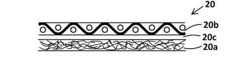
- FIG. 1 is a schematic diagram showing the configuration of one embodiment of a flame-blocking heat-insulating laminate.
- FIG. FIG. 2 is a schematic diagram showing the configuration of another embodiment of a flame-blocking and heat-insulating laminate.
- FIG. 2 is a schematic diagram showing the configuration of another embodiment of a flame-blocking heat-insulating laminate.
- FIG. 2 is a schematic diagram showing the configuration of another embodiment of a flame-blocking and heat-insulating laminate.
- FIG. 4 is a schematic diagram for explaining another embodiment of the flame-blocking heat-insulating laminate.
- FIG. 1 is a diagram showing an example of a flame-blocking and heat-insulating structure.
- FIG. 2 is a schematic diagram for explaining an example of use of the flame-blocking heat-insulating structure.
- FIG. 11A and 11B are diagrams showing another embodiment of the flame-blocking and heat-insulating structure.
- FIG. 2 is a schematic diagram for explaining an example of use of the flame-blocking heat-insulating structure.
- FIG. 2 is a schematic diagram for explaining an example of use of the flame-blocking and heat-insulating structure (battery cover).
- FIG. 11 is a diagram showing a state in which the battery cover shown in FIG. 10 is attached.
- FIG. 2 is a diagram for explaining a three-dimensional structure used in the evaluation test of three-dimensional moldability used in the examples.
- FIG. 2 is a diagram for explaining the evaluation method of molding stability employed in the examples.
- FIG. 2 is a diagram for explaining a flame test carried out in the examples.
- FIG. 1 is a diagram for explaining a heat insulation test 2 carried out in an example.
- the flame-shielding thermal insulation laminate of the present invention includes at least a flame-shielding thermal insulation layer and a prepreg layer, and corresponds to a semi-finished product for manufacturing a flame-shielding thermal insulation structure having a shape according to the application area. Users can manufacture a flame-shielding thermal insulation structure as a finished product having a planar shape with cuts such as slits, or a three-dimensional shape with a cylindrical shape, unevenness, bends, etc., by short-term heat treatment as necessary.
- the flame and heat insulating layer which is a component of the moldable flame and heat insulating laminate of the present invention, is a layer mainly composed of a fiber group formed by randomly entangled inorganic fibers having a heat resistance temperature of 1000°C or higher, and specifically contains the following components.
- the main component (inorganic fiber) constituting the flame-shielding heat-insulating layer is inorganic fiber with a heat resistance of 1000° C. or more.
- “Inorganic fibers with a heat resistance of 1000° C. or higher” refers to inorganic fibers with a glass transition point or softening point of 1000° C. or higher. Since the glass transition point is usually lower than the softening point, if the glass transition point is 1000° C. or higher, it can be said that the heat resistance is 1000° C. or higher. On the other hand, depending on the composition and type of inorganic fibers, the glass transition point may not be clearly indicated, and in the case of such inorganic fibers, it is sufficient that the softening point is 1000° C. or higher.
- the type of "inorganic fiber with a heat resistance of 1000°C or higher” needs to satisfy the above-mentioned requirement of "heat resistance of 1000°C or higher", and any of ceramic fiber, carbon fiber, silica fiber, metal fiber, biosoluble fiber, and high heat-resistant glass fiber can be used, and two or more of these inorganic fibers can be used in combination.
- the metal fibers include stainless steel fibers (which can withstand a heat of about 1400° C. depending on the type), etc.
- Metal fibers are superior in strength to other inorganic fibers.
- Carbon fibers are classified into polyacrylonitrile-based, pitch-based, and other carbon fibers depending on the raw material, but all of them have a graphite crystal structure in which six-membered carbon rings are stacked in layers, have a heat resistance of approximately 2000 to 2500°C, and are superior in terms of their light weight compared to other inorganic fibers.
- metal fibers and carbon fibers are conductive, it is preferable to use other inorganic fibers in applications requiring insulation.
- Ceramic fibers include alumina fibers (heat-resistant temperature: about 1300 to 1700° C.), mullite fibers (heat-resistant temperature: about 1400 to 1500° C.), alumina silicate fibers (silica:alumina (content) is 1:1 to 2:3, depending on the composition, usually heat-resistant temperature is about 1000 to 1200° C.), boron nitride fibers (heat-resistant temperature: about 2000 to 2400° C.), silicon carbide fibers (heat-resistant temperature: about 1200 to 1500° C.), zirconia fibers (heat-resistant temperature: about 2000 to 2200° C.), and crystalline silica fibers.
- Ceramic fibers have excellent corrosion resistance, they are preferably used in applications where there is a risk of exposure to chemicals, and alumina fibers are preferably used because of their high melting point and ease of availability. These ceramic fibers have excellent oxidation resistance and are therefore suitable for use as flame-shielding and heat-insulating layers in applications involving oxidizing atmospheres.
- Biosoluble fibers include alkaline earth silicate (AES) fibers (heat-resistant temperature approx. 1000°C) that contain 60-70% silica by weight and also contain alkali metals and alkaline earth metals in addition to silica. These are broadly classified as ceramic fibers, but are sometimes distinguished from the ceramic fibers mentioned above because they are biosoluble. Such biosoluble fibers have the property of being subject to rapid thermal shrinkage when exposed to flames, so they are preferably used in combination with other fibers in applications where exposure to high temperatures or flames is prolonged, or where flames are repeatedly exposed.
- AES alkaline earth silicate
- High heat-resistant glass fiber is glass fiber that has a silica content of 40-60% by weight and a high alumina content as another component, thereby increasing the heat resistance temperature.
- An example of this is T-glass (softening point 1050°C).
- amorphous fibers with a high silica content such as amorphous silica (SiO 2 ) content of 85% by weight or more, preferably 85% by weight or more, 90% by weight or more, or 93% by weight or more, can also be preferably used.
- Such high silica content fibers may have a heat resistance of 1000°C or more, regardless of the type of production method (e.g., acid treatment method, sol-gel method, etc.). They are distinguished from crystalline silica ceramic fibers in that they are amorphous.
- Amorphous silica fibers are insulating, so they can be used in applications where insulation is required, and from the viewpoint of production, they do not contain so-called shot, so they are preferable for applications in which the flame-shielding and heat-insulating layer surface is pressed against a material with low scratch resistance.
- the amorphous silica fiber used in the present invention is not particularly limited in terms of the manufacturing method, and may include silica fiber having hydroxyl groups at the ends and silica fiber that has been subjected to a calcination process.
- the hydroxyl groups can undergo a condensation reaction with each other at about 300 to 800°C, preferably about 350 to 700°C, to form new siloxane bonds (Si-O-Si bonds). They can also form hydrogen bonds with hydroxyl groups in matrix resins such as phenolic resins used in the prepreg layers described below, and can also contribute to increasing the bonding strength between the prepreg layers and the thermal insulation layer by undergoing dehydration condensation during the heat curing reaction.
- the water produced by dehydration condensation absorbs heat and evaporates, providing a cooling effect, so in applications aimed at preventing flaming due to thermal runaway in lithium-ion secondary batteries, it is preferable to use fibers with the hydroxyl groups remaining intact.
- silica fibers that contain hydroxyl groups may shrink due to heat. Therefore, in applications where exposure to high temperatures or flames is prolonged, or where the fibers are repeatedly exposed to flames, the rate of shrinkage due to heating can be reduced by first subjecting the fibers to heat treatment to reduce the amount of hydroxyl groups at the ends.
- silica fibers having hydroxyl groups at the ends examples include BELCOTEX® from BELCHEM GmbH.
- BELCOTEX® is an amorphous silica fiber made from silicic acid modified with alumina, and generally contains 90-97% by weight silica, about 3-9% by weight alumina, less than 0.5% by weight sodium oxide, and less than 0.5% by weight other components (ZrO 2 , TiO 2 , Li 2 O, K 2 O, CaO, MgO, SrO, BaO, Y 2 O 3 , La 2 O 3 , Fe 2 O 3 , and mixtures thereof).
- the softening point is in the range of 1050°C to 1200°C.
- Examples of the calcined silica fiber include the above-mentioned calcined BELCOTEX (registered trademark) and silica fiber available from recycled high-silica content glass fiber products.
- Silica fiber products which are mainly used for heat-resistant inorganic fiber products, are often used in applications where they are exposed to high heat or flames. In addition, during recycling, they are often subjected to high-temperature heating and crushing treatment in addition to chemical treatment. Silica fibers recovered from recycled products after such treatment can be used as fired silica fibers.
- the temperature of the heat treatment carried out in the recycling process varies depending on the type and material of the target recycled product, but is usually 350 to 700° C. in the case of recovering inorganic fibers.
- staple fibers having a fiber diameter of about 1 to 13 ⁇ m, preferably about 5 to 10 ⁇ m, and a length of 1 to 50 mm, preferably 3 to 40 mm, can be used.
- the flame and heat insulating laminate of the present invention is a laminate with a prepreg layer that is thermoformed, and therefore may contain staple fibers having a relatively long fiber length.
- Layered silicates are mainly composed of hydrous silicate minerals with a layered crystal structure, and have viscosity and plasticity. Specific examples include fibrous clay minerals such as sepiolite and attapulgite, and non-fibrous clay minerals such as kaolin minerals, halloysite, smectite, bentonite, vermiculite, talc, and mica.
- Fiber-like clay minerals are mineral powders whose particle shapes can be recognized under a microscope, such as fibrous, dendritic, needle-like, columnar, and rod-like.
- the aspect ratio which is the ratio of the width corresponding to the fiber diameter to the total length corresponding to the fiber length (total length/width), is 15 or more, preferably 50 or more, more preferably 100 or more, and 2000 or less, usually 1000 or less.
- Sepiolite and palygorskite are layered silicates classified as clay minerals having a fibrous morphology.
- the width equivalent to the fiber diameter is less than 0.1 ⁇ m, and the length (fiber length) that can be measured by microscopic observation is at most about 200 ⁇ m.
- the average primary particle size of these fibers is usually 10 ⁇ m to 100 ⁇ m, preferably 20 ⁇ m to 70 ⁇ m.
- the average particle size here means the particle size converted into a spherical particle size based on the end length projected two-dimensionally when the fiber has a curved or crimped fibrous form, and may be classified using a sieve based on the maximum particle size.
- Sepiolite's layered structure has a chain structure, is porous, has a large specific surface area, and has excellent adsorption properties. It is thixotropic, and becomes fibrous when crushed in a slurry using water as a dispersion medium. In addition, because it has excellent plasticity and flexibility, it can penetrate into the gaps between fibers, dry and solidify, and function as a binder between the fibers.
- Clay minerals (layered silicates) other than fibrous minerals include hydrous ferrosilicate minerals such as mica, kaolinite, smectite, montmorillonite, sericite, illite, glauconite, chlorite, and talc, or mixtures thereof. Of these, smectite, montmorillonite, bentonite, and mixtures thereof are preferably used.
- Bentonite is a natural clay mineral whose main component is montmorillonite.
- Smectite is a general term for a group of 2:1 type minerals, including montmorillonite, stevensite, and hectorite.
- Montmorillonite unit crystals are flat plate-like units consisting of tetrahedral sheets, octahedral sheets, and tetrahedral sheets, and multiple such unit crystals are stacked to form layers. Since it contains a large amount of water (for example, more than 10 times the amount of water in kaolin) between layers and can be peptized, it can penetrate into the gaps between fibers, and when it dries and solidifies, it forms a coating film and can function as a binder for these.
- the layered silicate described above exists as a powder having an average particle size of 300 ⁇ m or less, preferably 200 ⁇ m or less, more preferably 10 to 100 ⁇ m, in terms of circle equivalent diameter, before the slurry is prepared, but when mixed with water, it becomes viscous, adhesive, and plastic, and has the ability to form a self-coating film. Therefore, when the slurry is dried after being made into a paper, the clay can be solidified and coagulated in the gaps between the inorganic fibers. This is thought to suppress the elastic recovery of the flame-insulating heat-insulating layer after three-dimensional molding, and to improve the shape retention.
- the insulating material when the insulating material contains inorganic particles that impart heat insulation properties, which will be described later, the insulating material can also function as a binder between the inorganic fibers, increasing the cohesive force between the inorganic fibers and the insulating inorganic particles, thereby enabling the insulating inorganic particles to be stably held.
- the layered silicate minerals are preferably contained in an amount of 10 to 80 parts by weight, more preferably 20 to 70 parts by weight, and even more preferably 30 to 60 parts by weight, per 100 parts by weight of fiber. Since layered silicate minerals have poor flexibility in the absence of moisture, if the content in the flame-shielding heat-insulating layer becomes too high, the flexibility of the entire laminate is impaired, and it tends to become difficult to give it a three-dimensional shape.
- the flame and heat insulating layer may further contain an organic or inorganic binder.
- an organic or inorganic binder When the flame and heat insulating layer is produced by a papermaking method, the inclusion of any of these improves handling properties.
- organic binders examples include organic fibers having a fibrous form, powders, granules, and colloidal solutions of organic polymers.
- inorganic binders examples include water glass (sodium silicate), colloidal silica, and colloidal alumina.
- organic binders with a fibrous form examples include pulp fibers and thermoplastic resin fibers. These organic fibers become entangled with the inorganic fibers, which are the main components of the flame-resistant insulation layer, during the papermaking process, and soften and melt during heating and drying in the process of creating the flame-resistant insulation layer, allowing them to act as binders between the inorganic fibers.
- thermoplastic resins include polyester fibers, polypropylene fibers, polyethylene fibers, acrylic fibers, polyvinyl chloride fibers, vinylidene fibers, nylon fibers, vinylon fibers, polyvinyl alcohol-based fibers, etc.
- Thermoplastic resin fibers with a core-sheath structure using fibers with a low softening temperature in the surface layer may also be used. Since all of them have a softening point of about 120 to 200°C, they can melt and act as a binder in the drying process in the production of the flame-resistant insulation layer and the laminate production process, and when producing a flame-resistant insulation structure.
- thermoplastic resin fibers When using thermoplastic resin fibers as an organic binder, staple fibers with a fiber diameter of 3 ⁇ m to 50 ⁇ m, preferably 5 ⁇ m to 30 ⁇ m, and a fiber length of 1 to 20 mm, preferably 3 to 10 mm, are preferably used.
- the thermoplastic resin fibers must be homogeneously entangled with the inorganic fibers that form the main part of the flame-shielding heat-insulating layer, so it is preferable for them to have a length similar to that of the inorganic fibers.
- Organic binders having a form other than fiber include powdered or liquid polymers, such as latexes such as acrylic latex and (meth)acrylic latex; powdered thickening substances such as polyvinyl alcohol powder and starch; copolymers of styrene and butadiene, vinylpyridine, acrylonitrile, and copolymers of acrylonitrile and styrene.
- the organic binder should be contained in an amount sufficient to provide the flexibility required for the production of laminates and structures, or to mitigate the expansion and contraction of the sheets when the temperature rises during normal use.
- the organic binder if the content is too high, it can cause a decrease in the insulating properties of the finished flame-resistant thermal insulation structure.
- the organic components may oxidize to generate heat or generate decomposition gases.
- the above binders are contained in the dispersion at a solids concentration of 1 to 20% by weight, preferably 3 to 15% by weight, and more preferably 3 to 10% by weight.
- a solids concentration of 1 to 20% by weight, preferably 3 to 15% by weight, and more preferably 3 to 10% by weight.
- the flame-shielding heat-insulating layer may contain inorganic fibers with a heat-resistant temperature of less than 1000° C., so long as the inorganic fibers make up 10% by weight or less of the fiber components.
- inorganic fibers include general-purpose glass fibers (E glass, alkali glass, etc.), S glass fibers (heat-resistant temperature of about 800 to 900° C.), D glass fibers (heat-resistant temperature of about 700 to 800° C.), and rock wool (heat-resistant temperature of about 800° C.). Glass fibers with a heat resistance temperature of less than 1000° C. melt when exposed to flames, and therefore can play a role in compensating for thermal shrinkage when the main component fiber of the flame-shielding heat-insulating layer undergoes thermal shrinkage.
- the size (fiber length, fiber diameter) of these inorganic fibers is not particularly limited, but from the viewpoint of ease of entanglement with the main inorganic fiber, staple fibers with a fiber diameter of 1 to 13 ⁇ m, preferably 5 to 10 ⁇ m, and a length of 1 to 50 mm, preferably 3 to 40 mm, can be used.
- the flame-shielding heat-insulating layer is a sheet-like material having a thickness of 0.1 to 3 mm, preferably 0.1 to 2.0 mm, and more preferably 0.2 to 1 mm, in which inorganic fibers having a heat-resistant temperature of 1000° C. or higher are entangled in random directions and, if desired, the fibers are bound to each other with an organic or inorganic binder.
- a paper made by wet-processing a suspension containing the above-mentioned components is used.
- the components listed above i.e., the main components, inorganic fibers with a heat resistance of 1000°C or higher, layered silicate, and optionally an organic binder, are stirred and mixed in water, which is the dispersion medium, to prepare a slurry (suspension).
- the solids concentration of the slurry may be any concentration that allows the above components to be uniformly stirred and mixed. Specifically, the solids content is 0.01 to 10% by weight, preferably 0.05 to 3% by weight. In addition to the above, the solids content of the slurry may contain less than 15% by weight, preferably 10% by weight or less, and 5% by weight or less, of inorganic particles that impart heat insulation, as described below.
- the dispersion medium may be any medium capable of uniformly dissolving or dispersing the fibers and binder, and is preferably water.
- the dispersion medium may contain, as desired, aromatic hydrocarbons such as toluene, ethers such as tetrahydrofuran, ketones such as methyl ethyl ketone, alcohols such as isopropyl alcohol, N-methyl-2-pyrrolidone (NMP), dimethylacetamide, dimethylformamide, dimethylsulfoxide, etc.
- the slurry prepared above is papered using a paper machine, pressed to remove water, and then dried to obtain a sheet-like product.
- a papermaking machine a cylinder papermaking machine, a Fourdrinier papermaking machine, an inclined papermaking machine, an inclined short-wire papermaking machine, or a combination of these can be used.
- a cylinder papermaking machine, a Fourdrinier papermaking machine, a short-wire papermaking machine, an inclined papermaking machine, or a combination papermaking machine formed by combining the same or different types of papermaking machines from among these can also be used.
- various anionic, nonionic, cationic or amphoteric retention aids, drainage agents, dispersants, paper strength improvers and viscosity agents can be appropriately selected and added to the papermaking slurry as necessary within a range that does not impair the desired effects of the present invention.
- the drying temperature is at least the temperature at which the dispersion medium can evaporate, preferably at least 80°C, preferably at least 100°C, and is at most the decomposition temperature of the organic binder, preferably at most 120°C.
- the prepreg layer contained in the flame-shielding thermal insulation laminate of the present invention is a prepreg sheet in which an inorganic fiber base fabric is impregnated with a semi-cured thermosetting resin.
- the inorganic fibers constituting the base fabric are not particularly limited. Either inorganic fibers having a heat resistance of 1000° C. or higher that can be used in the flame-shielding heat-insulating layer or inorganic fibers having a heat resistance of less than 1000° C. may be used. From the viewpoint of availability, glass fiber and carbon fiber, which are inorganic reinforcing fibers generally used in prepregs, are preferably used. These are lightweight, easy to handle, and have excellent chemical resistance. The type of glass fiber is not limited, and E-glass fiber (glass transition point less than 800°C), which is a general-purpose glass, is preferably used from the viewpoint of cost. These base fabrics and fibers may be surface-treated as necessary to enhance adhesion with the thermosetting resin that is the matrix resin.
- the reinforcing fibers used in the base fabric are preferably continuous long fibers having a length of 10 mm or more, but may also be short fibers made by papermaking.
- the form of the base fabric is not particularly limited, and examples thereof include a fiber bundle made of a plurality of fibers, a woven or knitted fabric made by weaving or knitting fibers, a fiber sheet in which fibers are aligned in one direction, a nonwoven fabric or paper made by entangling fibers in random directions, or a combination of these.
- a woven fabric there is no limitation on the weaving method, and various woven fabrics such as plain weave, twill weave, and satin weave can be used.
- the thickness of the base fabric is usually 1 ⁇ m or more, 3 ⁇ m or more, 5 ⁇ m or more, or 10 ⁇ m or more, and usually 1000 ⁇ m or less, 800 ⁇ m or less, 500 ⁇ m or less, or 300 ⁇ m or less.
- the matrix resin contained in the prepreg layer is a monomer or oligomer of a phenolic resin, an epoxy resin, a polyimide resin, a melamine resin, a diallyl phthalate resin, etc., and is in a liquid or powder form.
- a thermosetting resin precursor When it is necessary to distinguish the matrix resin contained in the prepreg layer from a completely cured thermosetting resin, it is called a thermosetting resin precursor.
- phenolic resin examples include novolac type phenolic resin, resol type phenolic resin, aryl alkylene type phenolic resin, terpene modified phenolic resin, dicyclopentadiene type phenolic resin, etc.
- novolac type phenolic resin examples include phenol novolac resin, cresol novolac resin, bisphenol A novolac resin, etc.
- the epoxy resin examples include bisphenol type epoxy resins such as bisphenol A type epoxy resin, bisphenol F type epoxy resin, bisphenol S type epoxy resin, bisphenol E type epoxy resin, bisphenol M type epoxy resin, bisphenol P type epoxy resin, and bisphenol Z type epoxy resin, or derivatives thereof; novolac type epoxy resins such as phenol novolac type epoxy resin and cresol novolac type epoxy resin; aryl alkylene type epoxy resins such as biphenyl type epoxy resin and biphenyl aralkyl type epoxy resin; naphthalene type epoxy resin, anthracene type epoxy resin, phenoxy type epoxy resin, dicyclopentadiene type epoxy resin, norbornene type epoxy resin, adamantane type epoxy resin, and fluorene type epoxy resin. These may be used alone or in combination of two or more kinds.
- bisphenol type epoxy resins such as bisphenol A type epoxy resin, bisphenol F type epoxy resin, bisphenol S type epoxy resin, bisphenol E type epoxy resin, bisphenol M type epoxy resin, bisphenol P
- the precursor of the thermosetting resin is cured by a crosslinking reaction due to heating or in the presence of a curing agent, and therefore the matrix resin may contain a curing agent, a curing initiator, a reaction accelerator, etc., as necessary.
- the curing agent include phenolic resin curing agents, aliphatic amines, aromatic amines, dicyandiamide, dihydrazide compounds, and acid anhydrides.
- the curing accelerator examples include organic metal salts such as zinc naphthenate, cobalt naphthenate, tin octoate, and cobalt octoate; tertiary amines such as triethylamine and tributylamine; imidazoles, phenol compounds such as phenol, bisphenol A, and nonylphenol; organic acids such as acetic acid, benzoic acid, salicylic acid, and paratoluenesulfonic acid; phosphorus compounds such as triphenylphosphine and tritolylphosphine; and mixtures thereof.
- organic metal salts such as zinc naphthenate, cobalt naphthenate, tin octoate, and cobalt octoate
- tertiary amines such as triethylamine and tributylamine
- imidazoles phenol compounds such as phenol, bisphenol A, and nonylphenol
- organic acids such as acetic
- the weight (weight per unit area) of the base fabric of the prepreg layer is preferably 30 to 300 g/m 2 , more preferably 100 to 250 g/m 2 , and even more preferably 120 to 200 g/m 2.
- the resin content is appropriately selected depending on the type of resin and the type of base fabric, but is preferably 7 to 50% by weight, more preferably 10 to 30% by weight, and even more preferably 10 to 20% by weight.
- the amount of resin impregnated into the prepreg layer is preferably small from the viewpoint of heat insulation.
- the prepreg layer is formed by impregnating a reinforcing fiber base fabric with the matrix resin (thermosetting resin precursor).
- the impregnation method include a method of immersing the inorganic fiber base fabric in a liquid matrix resin solution or a dispersion of a matrix resin (solid), a method of applying the resin solution or dispersion to the fiber base fabric using various coaters, and a method of spraying the matrix resin (powder or liquid thermosetting resin precursor) onto the base fabric using a sprayer.
- a powder containing a resin component may be applied to a reinforcing fiber base fabric, and heated as necessary to melt at least a portion of the matrix resin, thereby impregnating the base fabric with the resin.
- the base fabric (or the fibers that make it up) can be heated until it is dry or semi-cured so that the matrix resin can be stably attached to the surface of the base fabric.
- the prepreg layer may be used in the manufacture of the laminate as a prepreg sheet produced alone, or a base fabric impregnated with the resin before being heated to a semi-cured state may be laminated on a layer constituting the laminate (e.g., a flame-resistant heat-insulating paper) and then heated to a semi-cured state.
- a laminate having a surface free of the matrix resin can be obtained by overlapping a prepreg sheet produced independently with a sheet made for a flame-blocking heat-insulating layer.
- the flame-shielding and thermal insulation laminate of the present invention may contain inorganic particles imparting thermal insulation properties in order to enhance thermal insulation.
- the inorganic particles imparting thermal insulation properties may be contained in either the flame-shielding and thermal insulation layer or the prepreg layer, or both.
- the inorganic particles having heat-insulating properties may be added to the slurry used in the wet papermaking process.
- thermosetting resin composition in which the heat insulating inorganic particles are contained as an inorganic filler in a liquid thermosetting resin precursor, or a dispersion in which the heat insulating inorganic particles are added to and mixed with a dispersion of a matrix resin is prepared, and the base fabric is immersed in the dispersion or coated on the base fabric.
- the inorganic particles that impart heat insulation include metal oxide aerogels such as silica aerogel, alumina aerogel, titania aerogel, zirconia aerogel, and celica aerogel, carbon aerogel, and porous or hollow inorganic particles such as porous particles formed by agglomeration of nanoparticles, glass bubbles, and shirasu balloons; and ceramic particles that can scatter radiant heat, such as titanium oxide, alumina, and silica that does not have a binder function (crystalline silica powder, amorphous silica, and the like).
- metal oxide aerogels such as silica aerogel, alumina aerogel, titania aerogel, zirconia aerogel, and celica aerogel, carbon aerogel, and porous or hollow inorganic particles such as porous particles formed by agglomeration of nanoparticles, glass bubbles, and shirasu balloons
- ceramic particles that can scatter radiant heat such as titanium oxide, alumina, and silica that does not have
- Ceramic particles capable of scattering radiant heat hollow or porous inorganic silica particles capable of obtaining an insulating effect by air and reducing weight
- silica particles having a long, tortuous air path capable of inhibiting thermal and electrical conductivity e.g., silica aerogel from CABOT Corporation, Carplex (registered trademark) from EVONIC Corporation, etc.
- Such silica particles include hydrophilic silica and hydrophobic silica, and either may be used.
- Porous silica particles such as silica aerogel are mesh-like aggregates (primary particles) of nano-sized silica particles (approximately 5 to 50 nm) that have nano-sized pores at a porosity of 70% by volume or more, preferably 80% by volume or more, and more preferably 90% by volume or more, and have an average primary particle diameter of 200 nm to 100 ⁇ m, preferably 1 ⁇ m to 80 ⁇ m.
- Such porous silica particles are manufactured by the sol-gel method, dry method (fumed silica), wet method (precipitated silica), etc., and the resulting particle diameter, aggregation state, and surface properties vary depending on the manufacturing method and manufacturing conditions.
- Aerogel particles within the above range can be obtained by pulverization. Aerogels with such a configuration can achieve a high level of insulation effect and can also be made lighter, as the numerous nano-sized pores can also hinder air convection.
- hydrophilic porous silica particles as the insulating inorganic particles is preferable because it is easy to mix homogeneously with other components when preparing a slurry in an aqueous medium.
- hydrophobic silica particles it is preferable to use them in a surface-treated state with a hydrophilic polymer dispersant such as cellulose nanofiber, PVA fiber, or starch, or a surfactant.
- a hydrophilic polymer dispersant such as cellulose nanofiber, PVA fiber, or starch, or a surfactant.
- the above-mentioned insulating inorganic particles can exist in a state where multiple types of fibers are entangled and held together, or in a state where they are dispersed in a matrix resin, so scattering of inorganic particle powder is suppressed even during processing steps such as cutting and punching.
- the flame and heat insulation laminate of the present invention is a sheet-like multilayer structure including the flame and heat insulation layer and the prepreg layer having the above-mentioned configuration.
- the flame-shielding thermal insulation laminate may be a laminate including only one flame-shielding thermal insulation layer and one prepreg layer, or a laminate including multiple layers of either one (preferably flame-shielding thermal insulation layers), or a laminate including an intervening layer between the flame-shielding thermal insulation layer and the prepreg layer, provided that at least one side is a flame-shielding thermal insulation layer.
- the flame-shielding heat insulating laminate may have a protective film laminated thereon as a surface layer. Examples of the intermediate layer include a graphite sheet and an adhesive layer.
- Representative structures of the flame-shielding heat-insulating laminate of the present invention include, for example, a two-layer structure 10 of a flame-shielding heat-insulating layer 10a and a prepreg layer 10b as shown in FIG. 1; a three-layer structure 20 in which a graphite sheet 20c is interposed as an intervening layer between a flame-shielding heat-insulating layer 20a and a prepreg layer 20b as shown in FIG. 2; a three-layer structure 30 in which both sides of a prepreg layer 30b are sandwiched between flame-shielding heat-insulating layers 30a as shown in FIG.
- FIG. 4(a) shows a laminate 40A in which the prepreg layer 40b is protected by a protective film 40d
- FIG. 4(b) shows a laminate 40B in which the flame-shielding heat-insulating layer 40a is protected by a protective film 40d
- the layers may be directly bonded together or may be laminated via an adhesive layer.
- Graphite sheet 20c refers to an expanded graphite sheet which can be formed into a sheet shape by rolling and molding expanded graphite, or a polymer-type expanded graphite sheet which can also be obtained by graphitizing a polymer film such as an aromatic polyimide sheet by heating it to a temperature of more than 2500°C under pressure in a reducing atmosphere.
- a graphite sheet (expanded graphite sheet) has high thermal conductivity in the planar direction but low thermal conductivity in the thickness direction. Therefore, by including a graphite sheet in a flame-shielding thermal insulation laminate, the flame-shielding and thermal insulation properties in the thickness direction of the sheet can be improved.
- the graphite sheet usually has a thickness of about 10 ⁇ m to 2 mm, although this depends on the manufacturing method. Due to limitations on the overall thickness of the flame-shielding thermal insulation laminate, it is preferable to use a sheet that is 1 mm or less, more preferably 0.5 mm or less, and even more preferably 10 ⁇ m to 200 ⁇ m (0.2 mm).
- the protective film 40d is laminated to protect the outer surface of either or both of the flame-shielding and heat-insulating layer and the prepreg layer. Since the semi-cured prepreg sheet has adhesive properties, it is preferable to protect it with a plastic film from the viewpoints of ease of handling and dust prevention. Furthermore, when the flame-shielding and heat-insulating layer contains inorganic particles that impart heat insulation, it is preferable to protect it with a plastic film from the viewpoints of preventing powdering of such particles and dust prevention.
- plastic film that can be used as the protective film
- plastic film typically, polyethylene film, polypropylene film, polyester film, polyamide film, etc. can be used.
- the thickness of the plastic film used as the protective film is typically 0.5 to 50 ⁇ m, and preferably about 1 to 30 ⁇ m. Such a protective film may be peeled off when used, or may be burned off early when used at high temperatures.
- the adhesive used may be either an organic binder or an inorganic binder.
- inorganic binders water glass, colloidal silica, etc. may be used.
- organic binders acrylic adhesives, etc. may be used.
- the flame-resistant heat-insulating laminate of the present invention can be produced, for example, by (i) laminating the films or sheets (e.g., flame-resistant heat-insulating paper, prepreg sheet, or graphite sheet) constituting each layer in order, and then bonding them by heating and pressing; (ii) applying an adhesive to a film or sheet (e.g., flame-resistant heat-insulating paper or prepreg sheet) as a substrate, and pasting the film or sheet to be laminated; (iii) laminating a base fabric of a prepreg layer on the flame-resistant heat-insulating paper, then applying a matrix resin of the prepreg layer and impregnating the base fabric, and then heating the matrix resin until it is in a semi-cured state.
- the method (i) is preferred. This makes it easy to produce a laminate having a flame-resistant heat-insulating layer surface where the matrix resin is not exposed.
- the flame-shielding heat insulating laminate having the above-mentioned structure is a flexible sheet, and although it depends on the laminate structure and the thickness of each layer constituting the sheet, it is usually 0.3 mm or more, preferably 0.5 mm or more, 0.8 mm or more, and usually 5 mm or less, preferably 3.5 mm or less, 3.0 mm or less, 2.5 mm or less, and can be 2 mm or less depending on the configuration of each layer and the laminate structure. It can be thinned to the desired thickness by applying pressure during curing. If it exceeds 5 mm, the flexibility decreases, making it difficult to give a three-dimensional shape, and the reduced flexibility also tends to make the handling and distribution of the product poor.
- the flame-resistant heat-insulating laminate of the present invention in addition to the flame-resistant effect based on the flame-resistant heat-insulating layer, can be formed or pressure-molded into a desired shape by secondary processing. It can be provided to users in the form of a sheet, which the users can then mold into a desired shape, or it can be marketed with a three-dimensional shape (three-dimensional structure).
- the flame-shielding heat insulating laminate of the present invention is usually provided as a sheet. Because it is flexible, it can be conveniently transported and distributed as a long strip wrapped around a spool or core. In other words, the flame-shielding heat insulating laminate of the present invention can be distributed as a semi-finished product, and the user can process and mold it into the desired shape depending on the application area to make a finished product.
- the flame barrier heat insulating structure of the present invention is formed by completely curing the thermosetting resin of the prepreg layer contained in the flame barrier heat insulating laminate of the present invention, thereby imparting and fixing a predetermined shape.
- the flame-shielding heat-insulating laminate of the present invention is soft and flexible, so it can be processed and molded in the same way as a general prepreg sheet.
- secondary processing such as perforation and cutting, and then heating and curing, a flame-shielding heat-insulating structure having an opening, a slit, or a desired two-dimensional shape can be manufactured.
- a flame-shielding heat-insulating structure having a three-dimensional shape such as a cylindrical shape, a bellows shape, a U-shaped cross section, or a folded U-shaped cross section can be manufactured.
- the heating conditions for fixing the shape (molding) are heating conditions that can completely cure the thermosetting resin used in the prepreg layer, and depend on the type of thermosetting resin. In the case of phenolic resin, heating is usually performed at about 160 to 280°C for about 30 seconds to 30 minutes. Heating may be performed under pressure as necessary. The pressure may be appropriately selected depending on the laminate to be used. In the case of a thin laminate that has already been pressed, the pressure required for imparting a shape may be applied, and the laminate may be thinned to a desired thickness by pressing.
- the flame-barrier heat-insulating structure of the present invention obtained in the manner described above can be given a three-dimensional shape based on the molding die, and there is almost no elastic recovery to the original shape after molding, making it excellent in moldability and shape stability.
- silica fibers having hydroxyl groups at their ends are used as the silica fibers contained in the flame-proof thermal insulation layer, the bonding strength with the flame-proof thermal insulation layer is increased by heat curing of the prepreg layer, and therefore the prepreg layer has excellent shape stability after being formed into a desired shape.
- the flame-insulating heat-insulating structure of the present invention obtained as described above comprises a flame-insulating heat-insulating layer and a fiber-reinforced resin layer (cured product of the prepreg layer).
- the flame and heat insulating layer corresponds to the flame and heat insulating layer of the flame and heat insulating laminate used as a raw material.
- the fiber reinforced resin layer is a cured product of the prepreg layer of the flame and heat insulating laminate, and corresponds to a cured product of the thermosetting resin contained in the prepreg layer.
- the flame-shielding heat insulating structure also contains the corresponding layer.
- the layer structure of the finished flame-insulating insulation structure corresponds to the layer structure of the flame-insulating insulation laminate used as the raw material, so that if the flame-insulating insulation laminate contains multiple flame-insulating insulation layers, the finished flame-insulating insulation structure will also contain multiple flame-insulating insulation layers.
- the flame-retaining insulation laminate contains a protective film, it is preferable to peel off the protective film before molding. If the finished flame-retaining insulation structure is to be marketed, the surface of the flame-retaining insulation structure may be protected with a protective film. In such cases, the protective film may be attached to the surface after molding.
- the thickness of the flame-resistant insulating structure can be made thinner than the thickness of the flame-resistant insulating laminate used as the raw material.
- the thickness of the flame-resistant insulating structure as a finished product can be set to the target thickness by adjusting the pressure applied during molding. Therefore, the thickness of the flame-resistant insulating structure depends on the thickness of the flame-resistant insulating laminate used, but is usually 0.5 to 5.0 mm, preferably 0.5 to 3.5 mm, more preferably 0.5 to 3 mm, and even more preferably 0.5 to 2.5 mm.
- the flame-insulating heat-insulating layer is used so as to abut against the portion requiring flame insulation.
- the flame-shielding heat-insulating layer does not burn or break even when exposed to flame for 10 minutes, so it can prevent the flame from spreading to the back side.
- the fibers that are the main component of the flame-shielding heat-insulating layer are powdered when exposed to flame for 10 minutes, making it difficult to maintain the shape.
- the flame-shielding heat-insulating structure of the present invention can maintain the intended shape by delaying the spread of flame to the fiber-reinforced resin layer, so that even if the flame-shielding heat-insulating layer is powdered by exposure to flame, it can still function as a flame-shielding heat-insulating layer.
- a flame-resistant insulation laminate with flame-resistant insulation layers on both sides can be used, as shown in Figure 3. If both sides are flame-resistant insulation layers, this is preferable because the second flame-resistant insulation layer can further prevent the spread of fire even if carbonization of the fiber-reinforced resin layer progresses.
- the flame-shielding heat-insulating structure of the present invention can be used as a partition between adjacent batteries in a battery pack in which multiple batteries are combined.
- silica fibers having hydroxyl groups as the constituent fibers of the flame-shielding heat-insulating layer, it is possible to delay the spread of fire to other batteries even if one battery included in the battery module experiences thermal runaway.
- Cylindrical flame-shielding heat-insulating structure For example, as shown in FIG. 5, a cylindrical flame-shielding heat-insulating laminate 2 in the form of a long strip is wound around a cylindrical core material 1, and then heated and cured to produce a cylindrical flame-shielding heat-insulating structure.
- a cylindrical flame-shielding heat-insulating structure can be used as a partition wall of a battery module in which a plurality of cylindrical batteries are arranged in parallel. With a predetermined number of cylindrical flame-shielding heat-insulating structures installed, a cylindrical battery can be set in each cylinder, which is also useful for improving the productivity of the battery module.
- the use of a partition wall made of a flame-shielding heat-insulating structure helps to suppress thermal runaway of the batteries in the battery module.
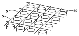
- the flame-shielding insulation structure 5 shown in Fig. 6 is a sheet-like flame-shielding insulation structure with multiple slits 5a formed therein by punching or the like. By fitting multiple flame-shielding insulation structures 5 together at the slits 5a, such a flame-shielding insulation structure 5 can be used as a thermal runaway suppression partition wall of a battery module equipped with cylindrical batteries 60, as shown in Fig. 7.
- the slitting may be carried out in the state of a semi-finished flame-shielding heat insulating laminate (sheet), or after heat curing.
- honeycomb-shaped fire-resistant heat-insulating structure The fire-resistant heat-insulating structure 6 shown in Fig. 8 is formed into a repeating shape having a substantially U-shaped cross section. By combining such fire-resistant heat-insulating structures 6 with an adhesive or by fitting slits, it is possible to manufacture a honeycomb-shaped fire-resistant heat-insulating structure as shown in Fig. 9, for example.
- a honeycomb-shaped flame-insulating and heat-insulating structure can be used as a partition wall having a thermal runaway suppression function in a battery module having a plurality of cylindrical batteries 60 arranged side by side, as shown in Fig. 9.
- using the honeycomb-shaped flame-insulating and heat-insulating structure as a partition wall of a battery module not only improves the productivity of the battery module, but also helps suppress thermal runaway of the batteries in the battery module.
- Battery cover for suppressing thermal runaway Figure 10 shows a flame-shielding heat-insulating structure that can be used as a battery module 100 in which a plurality of batteries 100a are arranged in parallel and stored/packaged in a housing 100b, and as a cover 70 that covers the upper surface of the battery of the battery module 100.
- a battery module 100 in which a plurality of batteries 100a are arranged in parallel and stored/packaged in a housing 100b, and as a cover 70 that covers the upper surface of the battery of the battery module 100.
- the high-temperature electrolyte may rain down on other batteries in the housing 100b, causing thermal runaway and ignition of the other batteries.
- the battery cover 70 can be used to prevent such ejected high-temperature liquid (debris) from raining down on the battery elements 100a in the same battery module 100.
- the battery cover 70 which is a flame-resistant heat-insulating structure, is produced, for example, by heating and pressurizing the two-layered flame-resistant heat-insulating laminate 10 shown in FIG. 1 using a mold, and then perforating it.
- the flame-resistant heat-insulating layer 10a is used so that it faces the battery.
- 71 is a groove formed along the stacking direction in which multiple batteries are stacked, and the groove 71 and dam 73, which become the liquid flow path, are molded to extend along the longitudinal direction, which is the direction of liquid flow, so as to become a flow path for high-temperature liquid.
- the bottom surface of the groove 71 i.e., the side that contacts the liquid flowing through the flow path, is the hardened product (thermosetting resin layer) of the prepreg layer 10b.
- a bank portion 74 is extended on the side of the battery cover 70 opposite the groove of the dam portion.
- Through holes 72, 72... are provided at a predetermined interval in the groove 71 of the battery cover 70, and are through holes through which the protrusions 101 of the battery 100a pass.
- the battery cover 70 is fixed to the top surface of the battery 100a by inserting the protruding terminals into the through holes 72.
- Figure 11 shows the battery cover 70 applied to a battery module 100 consisting of stacked prismatic batteries 100a.
- thermosetting resin layer or the flame-proof and heat-insulating layer contains insulating inorganic particles, this not only provides flame insulation, but also insulates against the thermal conduction of the debris' heat, thereby contributing to delaying the thermal conduction to batteries that make up the battery module 100 but are located away from the thermally runaway battery.
- the thermal runaway suppression battery cover 70 configured as described above is useful for preventing and avoiding heat transfer and fire spreading through the high-temperature liquid, particularly in the event of an ejection of high-temperature liquid, not only to batteries adjacent to the high-temperature liquid and the battery that has gone into thermal runaway, but also to batteries located farther away in the module.
- ⁇ The average value of ⁇ 1 and ⁇ 2 is less than 2°.
- ⁇ The average value of ⁇ 1 and ⁇ 2 is 2° to 5°.
- ⁇ The average value of ⁇ 1 and ⁇ 2 is 5° to 8° ⁇ : The average value of ⁇ 1 and ⁇ 2 is more than 8°
- Flame test flame retardancy
- the flame-blocking insulation structures were flame tested using a burner providing a flame temperature of 1000° C. in air.
- a sheet-like test sample 150 mm ⁇ 150 mm was stretched using metal clips as shown in FIG. 14, and one side of the sample piece was heated for 10 minutes by a burner flame fixed horizontally.
- the state of the flame on the surface opposite to the surface exposed to the flame (rear surface) and the state of the sheet after 10 minutes were observed and evaluated according to the following criteria.
- ⁇ No flame was observed on the back during the burner test, and the flame-blocking and heat-insulating layer remained after the test.
- Thermal insulation test 1 During the flame test, the temperature of the surface opposite the flame (back side) was measured. A calibration curve for the relationship between adiabatic temperature and thickness was created, and the measured temperatures were converted to temperatures for a thickness of 1.6 mm based on this. The converted temperatures are shown below.
- Thermal insulation test 2 15 a two-layer flame-shielding thermal insulation laminate (150 mm ⁇ 150 mm) 10 to be evaluated was placed on a hot plate (100 mm ⁇ 100 mm ⁇ thickness 10 mm) 11 heated to 700° C. so that the flame-shielding thermal insulation layer 10a was in contact with the hot plate. After maintaining this state for 3 minutes, the temperature of the upper surface of the prepreg layer 10b was measured with a temperature sensor.
- Glass fiber E-glass fiber (fiber diameter 9 ⁇ m, fiber length 3 to 6 mm) was used.
- Binder/Organic Fiber As the organic fiber binder, polyester fiber (fiber diameter 5-12 ⁇ m, fiber length 3-6 mm) or PVA fiber (fiber diameter 5-12 ⁇ m, fiber length 3-6 mm) was used.
- Inorganic Binder Snowtex 40 (colloidal silica in which spherical silica having an average particle size of 22 nm is dispersed) manufactured by Nissan Chemical Industries, Ltd. was used.
- Prepreg Layer The following prepreg sheet is made of E-glass fiber base fabric (plain weave fabric).
- ⁇ Prepreg sheet 1 (PR1) A prepreg sheet obtained by impregnating a base fabric with a resol type liquid phenolic resin (Shounol by Aica Kogyo Co., Ltd.). Glass fiber weight (basis weight) 200 g/m 2 , resin content 20 wt %, thickness 0.2 mm.
- Prepreg sheet 2 A resin composition was prepared by adding and mixing 30 parts by weight of silica aerogel (average particle size 30 ⁇ m) manufactured by CABOT Corporation as heat insulating inorganic particles to the liquid phenolic resin (precursor) used in prepreg sheet 1 per 100 parts by weight of the phenolic resin, and a base fabric was immersed in the composition and dried to prepare a prepreg sheet 2 having a thickness of 0.5 mm.
- Prepreg sheet 3 This is a prepreg sheet (thickness 0.2 mm) in which the content of the liquid phenolic resin (resol type) used in PR1 was reduced to 12 wt %.
- Each inorganic fiber paper was placed in a mold and heated and pressurized at 165°C for 5 minutes to produce a molded body with grooves as shown in Figure 12, and the three-dimensional moldability was evaluated.
- Flame-retaining heat-insulating laminate No. 4-6 The inorganic fiber paper (SF) and prepreg sheet (PR) prepared above were combined as shown in Table 2 and pressed at 120° C. for 10 seconds to prepare three-layer laminates (both sides of the prepreg layer were sandwiched between flame-shielding and heat-insulating layers) Nos. 4 to 6 having the thicknesses shown in Table 2. The obtained laminates were bonded to such an extent that they could not be peeled off by hand.
- the obtained sheet-shaped flame-resistant heat insulation laminates No. 4 to 6 were heated and pressed at 170°C for 10 minutes to produce molded bodies with grooves as shown in Figure 12, and their three-dimensional moldability was evaluated.
- the prepreg layer was completely cured to become a thermosetting resin layer (formation of GFRP), resulting in sheet-shaped flame-resistant heat insulation structures No. 4 to 6.
- Nos. 1 to 3 are cases where only the flame-shielding and heat-insulating paper was used. Although the paper has flame-shielding and heat-insulating properties, it was not possible to give the paper a stable shape by simply applying heat and pressure.
- Nos. 4 to 6 are examples of the flame-shielding heat-insulating laminate of the present invention. All of them could be molded in three dimensions.
- the flame-shielding heat-insulating structures corresponding to the finished products were able to exhibit flame-shielding properties in flame tests, and also ensured heat insulation properties comparable to those of the flame-shielding heat-insulating paper alone.
- a comparison of No. 2 and No. 3 shows that the inclusion of inorganic particles that impart heat insulation can further improve the insulation.
- a comparison of No. 5 and No. 6 shows that the inclusion of inorganic particles that impart heat insulation in the prepreg layer improves the insulation of the laminate, but the improvement is smaller than when inorganic particles that impart heat insulation are added to the flame-shielding insulation layer alone.
- a flame-shielding and heat-insulating layer (about 1.6 mm) was prepared in the same manner as in (A-2) above, except that the composition of the papermaking slurry was changed as shown in Table 3.
- Two types of prepreg layers (thickness 0.5 mm) were prepared, each having a glass fiber base fabric impregnated with phenol resin in an amount of 12% by weight or 20% by weight.
- flame-resistant and heat-insulating papers and prepreg sheets having different compositions were combined and pressed at 120° C. for 10 seconds to produce two-layered flame-resistant and heat-insulating laminates Nos. 11 to 20.
- the obtained flame-shielding and heat-insulating laminates No. 11 to 20 were hot-pressed (165°C, 5 minutes) to produce molded bodies as shown in Fig. 13(1), and the molding stability was evaluated. The results are shown in Table 3.
- the results of flame-shielding and heat-insulating structures No. 11 to 20 reveal the following: Increasing the matrix resin content of the prepreg layer can improve the molding stability (comparison between No. 11 and No. 12), but by including layered silicate (fibrous clay mineral) in the flame-shielding heat-insulating layer, the molding stability can be improved without increasing the matrix resin content of the prepreg layer (No. 13 to 20).
- layered silicate fibrous clay mineral
- the silica fiber containing hydroxyl groups had better molding stability than the silica fiber after heat treatment (comparison between No. 13 and No. 15, and between No. 14 and No. 16). This is thought to be because some of the hydroxyl groups contained in the silica fiber condensed with the matrix resin of the prepreg layer, increasing the bonding strength.
- Inorganic fiber paper for a flame-shielding heat-insulating layer having the composition shown in Table 4 was prepared.
- the prepared inorganic fiber paper was combined with a prepreg sheet (PR3) and pressed at 120°C for 10 seconds to prepare two-layered flame-shielding heat-insulating laminates No. 21 and 22, and the heat insulation and molding stability were evaluated based on the above evaluation test.
- the heat insulation test 2 was similarly performed on the flame-shielding heat-insulating layer alone used in No. 21. The results are also shown in Table 4.
- a comparison of No. 21 and No. 22 shows that when the flame-blocking insulation layer contains inorganic particles that provide thermal insulation, it is possible to obtain improved thermal insulation without impairing molding stability. Also, a comparison of No. 21 with the Reference Example shows that the presence of the prepreg layer reduces thermal insulation, but the inclusion of inorganic particles that provide thermal insulation reduced the temperature by about 40°C. It is believed that the inclusion of inorganic particles that provide thermal insulation in the flame-blocking insulation layer provides a higher thermal insulation effect than the inclusion of the prepreg layer.
- the flame-shielding heat insulating laminate of the present invention can be handled and distributed as a semi-finished sheet-like product, and users can mold it into a desired shape by applying heat and pressure, making it useful as a general-purpose flame-shielding heat insulating material.
- a flame-insulating and heat-insulating structure having a desired shape produced using the flame-insulating and heat-insulating laminate of the present invention has flame-insulating and heat-insulating properties similar to conventional flame-insulating and heat-insulating materials.
Landscapes
- Engineering & Computer Science (AREA)
- General Engineering & Computer Science (AREA)
- Mechanical Engineering (AREA)
- Textile Engineering (AREA)
- Manufacturing & Machinery (AREA)
- Chemical & Material Sciences (AREA)
- Chemical Kinetics & Catalysis (AREA)
- Electrochemistry (AREA)
- General Chemical & Material Sciences (AREA)
- Laminated Bodies (AREA)
Priority Applications (3)
| Application Number | Priority Date | Filing Date | Title |
|---|---|---|---|
| EP23891470.9A EP4582249A4 (en) | 2022-11-15 | 2023-11-10 | Flame-shielding heat-insulating laminate and flame-shielding heat-insulating structure using same |
| US19/115,845 US20260034765A1 (en) | 2022-11-15 | 2023-11-10 | Flame barrier insulating laminate and flame barrier insulating structure using the same |
| JP2024558822A JPWO2024106321A1 (https=) | 2022-11-15 | 2023-11-10 |
Applications Claiming Priority (2)
| Application Number | Priority Date | Filing Date | Title |
|---|---|---|---|
| JP2022182339 | 2022-11-15 | ||
| JP2022-182339 | 2022-11-15 |
Publications (1)
| Publication Number | Publication Date |
|---|---|
| WO2024106321A1 true WO2024106321A1 (ja) | 2024-05-23 |
Family
ID=91084646
Family Applications (1)
| Application Number | Title | Priority Date | Filing Date |
|---|---|---|---|
| PCT/JP2023/040510 Ceased WO2024106321A1 (ja) | 2022-11-15 | 2023-11-10 | 遮炎断熱積層体及びこれを用いた遮炎断熱構造体 |
Country Status (4)
| Country | Link |
|---|---|
| US (1) | US20260034765A1 (https=) |
| EP (1) | EP4582249A4 (https=) |
| JP (1) | JPWO2024106321A1 (https=) |
| WO (1) | WO2024106321A1 (https=) |
Cited By (3)
| Publication number | Priority date | Publication date | Assignee | Title |
|---|---|---|---|---|
| CN118927732A (zh) * | 2024-07-25 | 2024-11-12 | 南京工业大学 | 一种抑制电芯间热蔓延的陶瓷纤维防火板 |
| WO2026018738A1 (ja) * | 2024-07-19 | 2026-01-22 | イビデン株式会社 | 熱伝達抑制シート及び組電池 |
| WO2026083178A1 (en) * | 2024-10-14 | 2026-04-23 | 3M Innovative Properties Company | Pleated thermal insultative layer |
Citations (12)
| Publication number | Priority date | Publication date | Assignee | Title |
|---|---|---|---|---|
| JPH06328599A (ja) * | 1993-05-07 | 1994-11-29 | Ciba Geigy Ag | 高温1100℃燃焼貫通耐性複合サンドイッチパネル |
| US20180134002A1 (en) * | 2016-11-16 | 2018-05-17 | Tex Tech Industries, Inc. | Woven, nonwoven, and expandable graphite composite material |
| JP2018179010A (ja) * | 2017-04-03 | 2018-11-15 | 井前工業株式会社 | 耐火断熱シート |
| JP2019148031A (ja) | 2018-02-27 | 2019-09-05 | 井前工業株式会社 | 三次元形状成形体及びその製造方法 |
| WO2019187313A1 (ja) | 2018-03-30 | 2019-10-03 | 三洋電機株式会社 | 電源装置及びこの電源装置を備える電動車両及び蓄電装置 |
| WO2021095279A1 (ja) | 2019-11-15 | 2021-05-20 | 井前工業株式会社 | 複合型断熱材及びその製造方法 |
| JP2021096935A (ja) * | 2019-12-16 | 2021-06-24 | 三菱製紙株式会社 | 熱暴走抑制耐火シート |
| JP2021531631A (ja) | 2018-07-26 | 2021-11-18 | スリーエム イノベイティブ プロパティズ カンパニー | 電気自動車電池用途の耐炎性材料 |
| WO2022071141A1 (ja) * | 2020-09-29 | 2022-04-07 | 東レ株式会社 | 成形用基材およびそれを用いた成形品とその製造方法 |
| CN217562670U (zh) * | 2022-03-15 | 2022-10-11 | 浙江葆润应用材料有限公司 | 一种抗冲击隔热结构、电池组及电池包 |
| WO2022264661A1 (ja) * | 2021-06-17 | 2022-12-22 | ジャパンコンポジット株式会社 | 積層品 |
| WO2023157781A1 (ja) * | 2022-02-15 | 2023-08-24 | 井前工業株式会社 | 熱暴走抑制シート及びこれを用いた組電池及び組電池モジュール |
Family Cites Families (1)
| Publication number | Priority date | Publication date | Assignee | Title |
|---|---|---|---|---|
| KR20160077160A (ko) * | 2013-12-06 | 2016-07-01 | 미쯔비시 레이온 가부시끼가이샤 | 섬유 강화 열가소성 플라스틱을 이용한 적층 기재와 이것을 이용한 성형품의 제조 방법 |
-
2023
- 2023-11-10 JP JP2024558822A patent/JPWO2024106321A1/ja active Pending
- 2023-11-10 US US19/115,845 patent/US20260034765A1/en active Pending
- 2023-11-10 EP EP23891470.9A patent/EP4582249A4/en active Pending
- 2023-11-10 WO PCT/JP2023/040510 patent/WO2024106321A1/ja not_active Ceased
Patent Citations (12)
| Publication number | Priority date | Publication date | Assignee | Title |
|---|---|---|---|---|
| JPH06328599A (ja) * | 1993-05-07 | 1994-11-29 | Ciba Geigy Ag | 高温1100℃燃焼貫通耐性複合サンドイッチパネル |
| US20180134002A1 (en) * | 2016-11-16 | 2018-05-17 | Tex Tech Industries, Inc. | Woven, nonwoven, and expandable graphite composite material |
| JP2018179010A (ja) * | 2017-04-03 | 2018-11-15 | 井前工業株式会社 | 耐火断熱シート |
| JP2019148031A (ja) | 2018-02-27 | 2019-09-05 | 井前工業株式会社 | 三次元形状成形体及びその製造方法 |
| WO2019187313A1 (ja) | 2018-03-30 | 2019-10-03 | 三洋電機株式会社 | 電源装置及びこの電源装置を備える電動車両及び蓄電装置 |
| JP2021531631A (ja) | 2018-07-26 | 2021-11-18 | スリーエム イノベイティブ プロパティズ カンパニー | 電気自動車電池用途の耐炎性材料 |
| WO2021095279A1 (ja) | 2019-11-15 | 2021-05-20 | 井前工業株式会社 | 複合型断熱材及びその製造方法 |
| JP2021096935A (ja) * | 2019-12-16 | 2021-06-24 | 三菱製紙株式会社 | 熱暴走抑制耐火シート |
| WO2022071141A1 (ja) * | 2020-09-29 | 2022-04-07 | 東レ株式会社 | 成形用基材およびそれを用いた成形品とその製造方法 |
| WO2022264661A1 (ja) * | 2021-06-17 | 2022-12-22 | ジャパンコンポジット株式会社 | 積層品 |
| WO2023157781A1 (ja) * | 2022-02-15 | 2023-08-24 | 井前工業株式会社 | 熱暴走抑制シート及びこれを用いた組電池及び組電池モジュール |
| CN217562670U (zh) * | 2022-03-15 | 2022-10-11 | 浙江葆润应用材料有限公司 | 一种抗冲击隔热结构、电池组及电池包 |
Cited By (3)
| Publication number | Priority date | Publication date | Assignee | Title |
|---|---|---|---|---|
| WO2026018738A1 (ja) * | 2024-07-19 | 2026-01-22 | イビデン株式会社 | 熱伝達抑制シート及び組電池 |
| CN118927732A (zh) * | 2024-07-25 | 2024-11-12 | 南京工业大学 | 一种抑制电芯间热蔓延的陶瓷纤维防火板 |
| WO2026083178A1 (en) * | 2024-10-14 | 2026-04-23 | 3M Innovative Properties Company | Pleated thermal insultative layer |
Also Published As
| Publication number | Publication date |
|---|---|
| EP4582249A4 (en) | 2025-12-10 |
| EP4582249A1 (en) | 2025-07-09 |
| US20260034765A1 (en) | 2026-02-05 |
| JPWO2024106321A1 (https=) | 2024-05-23 |
Similar Documents
| Publication | Publication Date | Title |
|---|---|---|
| WO2024106321A1 (ja) | 遮炎断熱積層体及びこれを用いた遮炎断熱構造体 | |
| US20250316791A1 (en) | Thermal insulating/flame barrier sheet and battery pack and battery module package using the same | |
| JP2021531631A (ja) | 電気自動車電池用途の耐炎性材料 | |
| US20240250334A1 (en) | Thermal runaway suppression sheet and battery pack and/or battery module using the same | |
| JP2024103675A (ja) | シート状耐熱材および積層体 | |
| JP2024144134A (ja) | カバープロテクタ及びその製造方法、並びに電池モジュール | |
| JP7533183B2 (ja) | シート状耐熱材の製造方法および積層体 | |
| WO2023145883A1 (ja) | 防炎構造体及びその製造方法、並びに電池モジュール | |
| JP2023504272A (ja) | 電動ビークルの電池用途のための耐炎性材料 | |
| KR20240013196A (ko) | 연소 방지재, 그의 제조 방법, 적층체, 조전지 및 자동차 | |
| JP7533182B2 (ja) | シート状耐熱材の製造方法および積層体 | |
| CN115427630B (zh) | 阻燃纸 | |
| JP7513647B2 (ja) | 防炎材及びその製造方法、並びに電池モジュール | |
| WO2022270359A1 (ja) | 延焼防止材、組電池及び自動車 | |
| CN221352947U (zh) | 热传递抑制片以及电池组 | |
| CN121263564A (zh) | 柔性隔绝构件 | |
| WO2024142514A1 (ja) | 延焼防止材、積層体、組電池及び自動車 | |
| CN119343411A (zh) | 用于电动载具电池的热失控管理的膨胀片 | |
| WO2023182384A1 (ja) | 防炎構造体及びその製造方法、並びに電池モジュール | |
| JP2023170065A (ja) | 防炎シート及びその製造方法、並びに電池モジュール | |
| JP2023170683A (ja) | バスバー及び蓄電装置 | |
| CN222261203U (zh) | 保护盖罩以及电池模块 | |
| JP2026049685A (ja) | 積層型断熱・遮炎シート | |
| JP2024065516A (ja) | 断熱シート、組電池 | |
| JP2025022556A (ja) | 不燃紙又はシート |
Legal Events
| Date | Code | Title | Description |
|---|---|---|---|
| 121 | Ep: the epo has been informed by wipo that ep was designated in this application |
Ref document number: 23891470 Country of ref document: EP Kind code of ref document: A1 |
|
| WWE | Wipo information: entry into national phase |
Ref document number: 2024558822 Country of ref document: JP |
|
| WWE | Wipo information: entry into national phase |
Ref document number: 2023891470 Country of ref document: EP |
|
| ENP | Entry into the national phase |
Ref document number: 2023891470 Country of ref document: EP Effective date: 20250402 |
|
| NENP | Non-entry into the national phase |
Ref country code: DE |
|
| WWP | Wipo information: published in national office |
Ref document number: 2023891470 Country of ref document: EP |