WO2024101106A1 - 生体用電極 - Google Patents
生体用電極 Download PDFInfo
- Publication number
- WO2024101106A1 WO2024101106A1 PCT/JP2023/037841 JP2023037841W WO2024101106A1 WO 2024101106 A1 WO2024101106 A1 WO 2024101106A1 JP 2023037841 W JP2023037841 W JP 2023037841W WO 2024101106 A1 WO2024101106 A1 WO 2024101106A1
- Authority
- WO
- WIPO (PCT)
- Prior art keywords
- electrode
- tip
- center
- protrusions
- electrode protrusions
- Prior art date
- Legal status (The legal status is an assumption and is not a legal conclusion. Google has not performed a legal analysis and makes no representation as to the accuracy of the status listed.)
- Ceased
Links
Images





Classifications
-
- A—HUMAN NECESSITIES
- A61—MEDICAL OR VETERINARY SCIENCE; HYGIENE
- A61B—DIAGNOSIS; SURGERY; IDENTIFICATION
- A61B5/00—Measuring for diagnostic purposes; Identification of persons
- A61B5/24—Detecting, measuring or recording bioelectric or biomagnetic signals of the body or parts thereof
- A61B5/25—Bioelectric electrodes therefor
- A61B5/263—Bioelectric electrodes therefor characterised by the electrode materials
- A61B5/268—Bioelectric electrodes therefor characterised by the electrode materials containing conductive polymers, e.g. PEDOT:PSS polymers
-
- A—HUMAN NECESSITIES
- A61—MEDICAL OR VETERINARY SCIENCE; HYGIENE
- A61B—DIAGNOSIS; SURGERY; IDENTIFICATION
- A61B5/00—Measuring for diagnostic purposes; Identification of persons
- A61B5/24—Detecting, measuring or recording bioelectric or biomagnetic signals of the body or parts thereof
- A61B5/25—Bioelectric electrodes therefor
- A61B5/279—Bioelectric electrodes therefor specially adapted for particular uses
- A61B5/291—Bioelectric electrodes therefor specially adapted for particular uses for electroencephalography [EEG]
Definitions
- This disclosure relates to bioelectrodes.
- Bioelectrodes are known that are used to obtain bioinformation such as electroencephalograms, electrocardiograms, and electromyograms from changes in the electrical potential of a living body.
- bioelectrode described in Patent Document 1 can be given as an example of such a bioelectrode.
- the bioelectrode described in Patent Document 1 has a support member and multiple electrode members.
- the support member supports the multiple electrode members.
- the multiple electrode members are the parts that come into contact with the subject's body and protrude from the support member in a brush-like shape.
- the support member and the multiple electrode members are made of conductive rubber.
- the conductive rubber contains silicone rubber and silver powder.
- Biosignals related to brain waves and the like are weak signals of several tens of microvolts.
- large amounts of metal powder such as silver powder are used in the materials for bioelectrodes.
- the material becomes hard and the material costs increase.
- wearing the electrodes for a long period of time can cause pain. As a result, there is a risk that the desired measurement results will not be obtained.
- a biological electrode has a base having an installation surface, and a plurality of electrode protrusions that protrude from the installation surface, contain conductive particles and a rubber material, and contact a detection target to detect a biological signal, the plurality of electrode protrusions are arranged in a circle on the installation surface, the central axis of each of the plurality of electrode protrusions is inclined with respect to a normal line passing through the center of the installation surface, the center of the tip of each of the plurality of electrode protrusions is located radially outward from the center of the installation surface relative to the center of the base end, and each of the plurality of electrode protrusions is hollow.
- a bioelectrode has a base having an installation surface, and a plurality of electrode protrusions that protrude from the installation surface, contain conductive particles and a rubber material, and contact a detection target to detect a biosignal, the plurality of electrode protrusions are arranged in a circle on the installation surface, the central axis of each of the plurality of electrode protrusions is inclined with respect to a normal line passing through the center of the installation surface, the center of the tip of each of the plurality of electrode protrusions is located radially outward from the center of the installation surface, and each of the plurality of electrode protrusions has a hemispherical tip portion including the tip, and a split-cylindrical intermediate portion provided between the tip portion and the installation surface, the radially outer portion of the cylinder being cut along the normal line.
- the rigidity of the electrode protrusions can be reduced, reducing the risk of pain when the biomedical electrode is attached.
- the multiple electrode protrusions flexibly bend and spread outward when the biomedical electrode is attached, the contact area between the electrode protrusions and the subject's measurement site can be increased. This makes it possible to suppress a decrease in measurement accuracy.
- FIG. 2 is a side view of the biological electrode of the first embodiment.
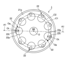
- FIG. 2 is a bottom view of the biological electrode of the first embodiment.
- 3 is a cross-sectional view taken along line A1-A1 in FIG. 2.
- 4 is an enlarged view of a portion of the electrode projections shown in FIG. 3.
- FIG. 11 is a cross-sectional view of a portion of an electrode member according to a second embodiment.
- FIG. 11 is a cross-sectional view of a portion of an electrode member according to a third embodiment.
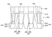
- FIG. 13 is a side view of an electrode member according to a fourth embodiment.
- FIG. 8 is a bottom view of the electrode member shown in FIG. 7 . 8 is a cross-sectional view of a portion of the electrode projections shown in FIG. 7 .
- FIG. 13 is a side view showing a modified example of a biological electrode.
- FIG. 1 is a side view of a biological electrode 1 of the first embodiment.
- Fig. 2 is a bottom view of the biological electrode 1 of the first embodiment.
- Fig. 3 is a cross-sectional view taken along the line A1-A1 in Fig. 2.
- the bioelectrode 1 shown in Figures 1, 2, and 3 is an electrode for detecting potential changes in a living body of a human or animal, etc., as a biosignal.
- the bioelectrode 1 is used in a state of contact with the surface of the living body to be detected.
- the bioelectrode 1 is electrically connected to a measuring device that generates bioinformation such as brain waves based on the biosignal from the bioelectrode 1.
- the living body to be detected may be referred to as the subject.
- the use of the bioelectrode 1 is not limited to measuring brain waves, but may be, for example, measuring bioinformation such as an electrocardiogram or electromyogram. Therefore, the part of the living body to which the bioelectrode 1 is contacted is not limited to the scalp, but may be, for example, an arm, leg, chest, or back, and does not have to be a part with hair. Furthermore, the use of the bioelectrode 1 is not limited to detecting biosignals, but may be, for example, providing electrical stimulation to the living body.
- the bioelectrode 1 comprises a support member 10, an electrode member 20, and a connector 30.
- the bioelectrode 1 extracts a biosignal from the subject via the connector 30 by contacting the tips 22t of the multiple electrode protrusions 22 of the electrode member 20 with the subject's body. Each part of the bioelectrode 1 will be described in order below.
- the support member 10 is a member that supports the electrode member 20.
- the support member 10 is made of an insulating material, i.e., a dielectric material.
- the insulating material include polymers such as silicone rubber, urethane rubber, fluororubber, and ethylene-propylene-diene terpolymer rubber. Ethylene-propylene-diene terpolymer rubber is EPDM. From the viewpoint of increasing the adhesion between the support member 10 and the electrode member 20, it is preferable that the insulating material is the same type of polymer as the polymer that constitutes the electrode member 20.
- the shape of the support member 10 is a disk shape.
- the support member 10 has a support surface 10a and a back surface 10b.
- the support surface 10a is a surface that supports the electrode member 20.
- the back surface 10b is a surface facing in the opposite direction to the support surface 10a.
- the support member 10 is formed with a through hole S0 and a plurality of first holes S1.
- Each of the through hole S0 and the plurality of first holes S1 is a hole that penetrates the support member 10 in the thickness direction, and opens on the support surface 10a and the back surface 10b, respectively.
- the through hole S0 is formed in the center of the support member 10 in a plan view.
- each first hole S1 is provided in one-to-one correspondence with a plurality of electrode protrusions 22 of the electrode member 20 described later.
- the width of each first hole S1 is constant throughout the entire area in the length direction.
- the cross-sectional shape of each first hole S1 is circular.
- planar shape of the support member 10 is circular in the example shown in FIG. 1, but is not limited to this and may be, for example, polygonal.
- the cross-sectional shapes of the through hole S0 and the first hole S1 are not limited to circular and may be, for example, polygonal, such as a square or pentagon.
- the support member 10 is provided as necessary, and may be omitted, or may be configured integrally with the electrode member 20.
- the electrode member 20 shown in FIG. 1 is a conductive member for contacting the surface of a living body.
- the electrode member 20 is made of a conductive elastic material.
- the elastic material includes a rubber material and conductive particles.
- the rubber material include silicone rubber, ethylene-propylene-diene terpolymer rubber, nitrile rubber, and urethane rubber. Among them, silicone rubber is preferably used as the rubber material from the viewpoint of biocompatibility.
- the conductive particles include carbon particles made of carbon black, carbon nanotubes, graphite, and the like, and metal particles made of metals such as silver and silver chloride, and metal compounds.
- the elastic material may include a fiber base material such as a nonwoven fabric or woven fabric made of a resin material or a carbon material, and may also include various additives.
- the electrode member 20 has a base 21 and a number of electrode protrusions 22.
- the base 21 and the number of electrode protrusions 22 may be formed of the same material or different materials.
- the base 21 is a portion of the electrode member 20 that supports multiple electrode protrusions 22.
- the base 21 is disk-shaped, and the outer shape of the base 21 in a plan view roughly matches the outer shape of the support member 10.
- the base 21 has an installation surface 21a and a surface 21b facing in the opposite direction to the installation surface 21a.
- the surface 21b facing in the opposite direction to the installation surface 21a is a surface that contacts the support surface 10a, and is joined to the support surface 10a by vulcanization adhesion or adhesive, etc.
- Multiple electrode protrusions 22 are installed on the installation surface 21a.
- a plurality of second holes S2 are formed in the base 21.
- the plurality of second holes S2 are holes that penetrate the support member 10 in the thickness direction, and open to the mounting surface 21a and the surface 21b facing in the opposite direction to the mounting surface 21a.
- the plurality of second holes S2 are provided in one-to-one correspondence with the plurality of electrode protrusions 22.
- the width of each second hole S2 is constant throughout the entire length.
- the cross-sectional shape of each second hole S2 is circular.
- planar shape of the base 21 is circular in the example shown in FIG. 1, but is not limited to this and may be, for example, polygonal.
- the planar shape of the base 21 may also be different from the planar shape of the support member 10.
- FIG. 4 is an enlarged view of a portion of the electrode protrusions 22 shown in FIG. 3.
- each of the electrode protrusions 22 is a protrusion protruding from the mounting surface 21a of the base 21.
- Each electrode protrusion 22 is formed of a single material, an elastic material having electrical conductivity, and functions as an electrode that contacts a detection target to detect a biosignal.
- Each electrode protrusion 22 is hollow and has an internal space S. The internal space S is connected to the second hole S2 of the base 21 described above. Since each electrode protrusion 22 is hollow, the amount of conductive particles can be reduced compared to when the electrode protrusions 22 are solid. Therefore, the rigidity of each electrode protrusion 22 can be reduced.
- the risk that the subject will feel pain when wearing the bioelectrode 1 can be reduced.
- the subject will not feel pain even if the bioelectrode 1 is worn for a long period of time.
- the amount of conductive particles can be reduced, material costs can be reduced.
- the multiple electrode protrusions 22 are arranged in a circle on the mounting surface 21a. More specifically, the multiple electrode protrusions 22 are arranged at equal angular intervals on a virtual circle C1 centered on the center O of the mounting surface 21a when viewed in the thickness direction of the base 21.
- the electrode protrusions 22 may not be arranged at equal angular intervals.
- a plurality of other electrode protrusions 22 may be arranged concentrically with the imaginary circle C1.
- the number of electrode protrusions 22 is nine in the example shown in FIG. 2, but is not limited to this and may be eight or less or ten or more. However, from the viewpoint of realizing stable contact between the living body and the electrode member 20, the number of electrode protrusions 22 is preferably three or more, and more preferably four or more.
- each electrode protrusion 22 has a base end 22p and a tip 22t.
- the base end 22p of each electrode protrusion 22 is connected to the base 21.
- the tip 22t of each electrode protrusion 22 contacts the surface of the living body.
- the circle connecting the base ends 22p of each electrode protrusion 22 is the aforementioned imaginary circle C1.
- the circle connecting the centers Op of the tips 22t of the electrode protrusions 22 is the imaginary circle C2.
- the imaginary circle C2 is located outside the imaginary circle C1. If the tip 22t is not a surface, the center Ot of the tip 22t coincides with the tip 22t.
- the center Ot of the tip 22t of each of the electrode protrusions 22 is located radially outward from the center O of the mounting surface 21a relative to the center Op of the base end 22p.
- the central axis O2 along the protruding direction of each electrode protrusion 22 is inclined with respect to the normal line O1 passing through the center O of the mounting surface 21a.
- the normal line O1 overlaps with the center line of the base 21. Due to this inclination, when the bioelectrode 1 is pressed against the subject, the multiple electrode protrusions 22 flexibly deform so as to spread radially outward from the tip 22t.
- each electrode protrusion 22 is hollow, so that when each electrode protrusion 22 deforms, each electrode protrusion 22 deforms so as to bend. Therefore, the contact area of each electrode protrusion 22 with the subject can be increased. This makes it possible to suppress a decrease in the measurement accuracy of the bioelectrode 1.
- the angle of inclination of the central axis O2 with respect to the normal O1 is not particularly limited, but from the viewpoint of ensuring good contact between the living body and the electrode member 20, it is preferably 10° or more, more preferably 10° or more and 45° or less, and even more preferably 10° or more and 30° or less. Note that this angle of inclination may be the same or different between the multiple electrode protrusions 22.
- each electrode protrusion 22 includes a tip 22t and has a convexly curved tip 220.
- the tip 220 is hemispherical in shape.
- the tip 220 of the electrode protrusion 22A has a convexly curved shape, which reduces the risk that the subject will feel pain when wearing the bioelectrode 1.
- the tip 220 of each electrode protrusion 22 is convexly curved in shape, the shape is not limited to this and can be any shape.
- each electrode protrusion 22 has a tapered shape. Therefore, the width W of each electrode protrusion 22 becomes smaller from the base end 22p to the tip 22t. Therefore, the width of the tip 220 is smaller than the width of the base end 22p. Since the width W of each electrode protrusion 22 becomes smaller from the base end 22p to the tip 22t, when the electrode member 20 is pressed against the subject, the electrode protrusions 22 are more likely to deform so as to spread radially outward, compared to when the width W is constant. Therefore, it is easier to increase the contact area of each electrode protrusion 22 with the subject. Furthermore, since the width W becomes smaller from the base end 22p to the tip 22t, the rigidity of the base end 22p and its vicinity can be maintained.
- the biological electrode 1 can be stably attached to the measurement site of the subject, and therefore, it is possible to suppress changes in the position of the measurement site.
- the width W of the electrode protrusion 22 may be constant from the base end 22p to the tip 22t.
- the thickness D between the inner wall surface and the outer wall surface of each electrode protrusion 22 is constant.
- a constant thickness D makes it easier to manufacture each electrode protrusion 22 than when the thickness D is not constant.
- the thickness D is not particularly limited, but from the viewpoint of ease of deformation, it is preferably 0.2 mm or more and 1.0 mm or less, and more preferably 0.4 mm or more and 0.6 mm or less.
- the thickness D may be the same or different between multiple electrode protrusions 22.
- the tip 220 of each electrode protrusion 22 does not have a hole that connects the internal space S to the outside. If a hole were formed in the tip 220, the rigidity of the tip 220 would be reduced more than necessary. As a result, when the tip 220 of each electrode protrusion 22 is pressed against the subject, the tip 220 is easily crushed. Therefore, there is a high possibility that only the tip 220 will be crushed without the area between the tip 220 and the base end 22p of each electrode protrusion 22 being deformed to bend. This makes it difficult to increase the contact area of each electrode protrusion 22 with the subject. In contrast, since the electrode protrusions 22 of this embodiment do not have such a hole, the multiple electrode protrusions 22 are easily deformed to spread radially outward, and therefore the contact area of each electrode protrusion 22 with the subject can be easily increased.
- each electrode protrusion 22 is circular. This reduces the risk of the subject feeling pain compared to when the cross-sectional shape of each electrode protrusion 22 is rectangular. Note that the cross-sectional shape of each electrode protrusion 22 is not limited to a circle, and may be a polygon such as a rectangle or a pentagon.
- the bus line B1 of each electrode protrusion 22 located farthest from the normal line O1 is parallel to the normal line O1.
- the bus line B2 of each electrode protrusion 22 located closest to the normal line O1 is inclined with respect to the normal line O1 so as to move away from the normal line O1 from the base end 22p to the tip end 22t.
- the height h of the electrode protrusion 22 is not particularly limited, but is preferably 6 mm or more and 15 mm or less. By having the height h within this range, the electrode protrusion 22 can be brought into good contact with the biological surface having hair. If the height h of the electrode protrusion 22 is too low, it may be difficult to maintain good contact of the electrode protrusion 22 with the biological surface having hair, depending on the condition of the subject's hair, etc. On the other hand, if the height h of the electrode protrusion 22 is too high, this is not preferable from the perspective of miniaturizing the biological electrode 1. Furthermore, when the electrode member 20 is molded using a mold, there is a tendency for releasability to deteriorate.
- the height h of the electrode protrusion 22 is the length from the base end 22p to the tip 22t of the electrode protrusion 22 in the thickness direction of the base 21, i.e., in the direction along the normal O1 of the installation surface 21a. From the viewpoint of ensuring good contact between the living body and the electrode member 20, it is preferable that the heights h of the multiple electrode protrusions 22 are equal to each other.
- the hardness of the material of each electrode protrusion 22, i.e., the conductive material including conductive particles and rubber material, is not particularly limited, but from the viewpoint of ease of deformation, it is preferable that the hardness be 40 degrees or more and 80 degrees or less on a type A durometer conforming to JIS K 6253.
- the connector 30 shown in FIG. 3 is a snap button type male connector, which is fitted into a female connector (not shown) that is electrically connected to a measuring device.
- the connector 30 has a first conductive member 31 and a second conductive member 32.
- the first conductive member 31 and the second conductive member 32 each have a flanged, bottomed cylindrical shape, and are made of a metal material such as stainless steel.
- the first conductive member 31 and the second conductive member 32 fit into each other.
- the first conductive member 31 has a first bottomed tubular portion 311 and a first flange portion 312.
- the first bottomed tubular portion 311 is substantially cylindrical with a bottom.
- the first flange portion 312 is connected to the open end of the first bottomed tubular portion 311.
- a portion of the first bottomed tubular portion 311 is inserted into the through hole S0 of the support member 10.
- the first flange portion 312 is in contact with the support surface 10a of the support member 10 and is flange-shaped extending radially outward from the open end of the first bottomed tubular portion 311.
- the second conductive member 32 has a second bottomed tubular portion 321 and a second flange portion 322.
- the second bottomed tubular portion 321 is substantially cylindrical with a bottom.
- the second flange portion 322 is connected to the open end of the second bottomed tubular portion 321.
- the inner diameter of the second bottomed tubular portion 321 is substantially equal to the outer diameter of the first bottomed tubular portion 311.
- the second bottomed tubular portion 321 is arranged to cover a part of the first bottomed tubular portion 311, and the first conductive member 31 and the second conductive member 32 are fitted together.
- the second flange portion 322 is in contact with the rear surface 10b of the support member 10 and is flange-shaped extending radially outward from the open end of the second bottomed tubular portion 321.
- the support member 10 is sandwiched between the first flange portion 312 and the second flange portion 322. This fixes the connector 30 to the support member 10.
- each electrode protrusion 22 is solid and formed from a single material containing conductive particles and rubber material, and the central axis O2 of each electrode protrusion 22 is inclined so as to expand radially relative to the normal line O1. This reduces the rigidity of each electrode protrusion 22, reducing the risk of feeling pain when wearing the biomedical electrode 1. Furthermore, since each electrode protrusion 22 flexes flexibly so as to expand outward when the biomedical electrode 1 is worn, the contact area between each electrode protrusion 22 and the measurement site of the subject can be increased. This makes it possible to suppress a decrease in measurement accuracy.
- FIG. 5 is a diagram showing a cross section of a portion of the electrode member 20A of the second embodiment. As shown in FIG. 5, the second embodiment is similar to the first embodiment except that the thickness between the inner wall surface and the outer wall surface of the electrode protrusion portion 22A of the electrode member 20A is not constant.
- the electrode protrusion 22A has a tip portion 220A and a thin portion 221.
- the tip portion 220A includes the tip 22t and is a convexly curved portion of the electrode protrusion 22A.
- the thin portion 221 is a portion of the electrode protrusion 22A located between the tip portion 220A and the installation surface 21a, and has a thickness D2 that is thinner than the thickness D1 of the tip portion 220A.
- each electrode protrusion 22A is likely to deform from near the center in the protruding direction of each electrode protrusion 22A. In other words, each electrode protrusion 22A is likely to bend while preventing crushing of the tip 220A. This makes it possible to increase the contact area of each electrode protrusion 22A with the subject. This improves measurement accuracy.
- Thickness D1 is not particularly limited, but from the viewpoint of suppressing crushing of the tip portion 220A, it is preferably 1 mm or more and 5 mm or less, and more preferably 2 mm or more and 3 mm or less.
- thickness D2 is not particularly limited, but from the viewpoint of ease of deformation, it is preferably 0.2 mm or more and 1.0 mm or less, and more preferably 0.4 mm or more and 0.6 mm or less. Note that thickness D1 and thickness D2 may be equal to or different from each other among the multiple electrode protrusion portions 22A.
- FIG. 6 is a diagram showing a cross section of a portion of an electrode member 20B of the third embodiment. As shown in FIG. 6, the third embodiment is similar to the first embodiment except that the thickness between the inner wall surface and the outer wall surface of the electrode protrusion portion 22B of the electrode member 20B is not constant.
- the electrode protrusion 22B has an inner portion 222 and an outer portion 223.
- the inner portion 222 is a portion located inside the circular truncated cone connecting the imaginary circles C1 and C2 shown in FIG. 2 described above.
- the outer portion 223 is a portion located outside the circular truncated cone.
- the inner portion 222 can also be said to be a portion located radially inward from an imaginary plane connecting the central axes O2 of the multiple electrode protrusions 22B shown in FIG. 6.
- the outer portion 223 can also be said to be a portion located radially outward from the imaginary plane.
- the thickness D4 of the outer portion 223 is thinner than the thickness D3 of the inner portion 222. Therefore, it is easier to reduce the rigidity of the outer portion 223 than the inner portion 222. Therefore, in this embodiment, compared to the first embodiment, when the electrode member 20B is pressed against the subject, the multiple electrode protrusions 22B are more likely to deform so as to spread radially outward. Therefore, it is easier to increase the contact area of each electrode protrusion 22B with the subject.
- Thickness D3 is not particularly limited, but from the viewpoint of increasing the rigidity of the inner portion 222 more than that of the outer portion 223, it is preferably 1 mm or more and 5 mm or less, and more preferably 2 mm or more and 3 mm or less.
- thickness D4 is not particularly limited, but from the viewpoint of ease of deformation, it is preferably 0.2 mm or more and 1.0 mm or less, and more preferably 0.4 mm or more and 0.6 mm or less. Note that thickness D3 and thickness D4 may be equal to or different from each other among the multiple electrode protrusions 22.
- FIG. 7 is a side view of the electrode member 20C of the fourth embodiment.
- FIG. 8 is a bottom view of the electrode member 20C shown in FIG. 7.
- FIG. 9 is a cross-sectional view of some of the electrode protrusions 22C shown in FIG. 7.
- the fourth embodiment is similar to the first embodiment except that some of the electrode protrusions 22C of the electrode member 20C are cut out.
- each electrode protrusion 22C has a tip portion 220 and an intermediate portion 225.
- the intermediate portion 225 is the portion of each electrode protrusion 22C between the tip portion 220 and the installation surface 21a.
- the shape of the intermediate portion 225 is a split cylinder shape in which the radially outer portion of a cylinder is cut along the normal line O1.
- the cross section of the intermediate portion 225 taken along the central axis O2 is an arc shape.
- the intermediate portion 225 is located radially inward of the imaginary circle C2.
- an opening 224 is provided on the side of each electrode protrusion 22C at a position away from the tip 22t.
- the opening 224 is provided radially outward from the normal line O1.
- the opening 224 is formed across the inner and outer wall surfaces of the electrode protrusion 22, and is a through hole that communicates with the internal space S.
- each electrode protrusion 22C is likely to deform from near the center in the protruding direction of each electrode protrusion 22C. Therefore, the contact area of each electrode protrusion 22C with the subject can be increased. This can improve the measurement accuracy.
- the opening area of the opening 224 is not particularly limited and can be any size.
- the opening areas of the multiple electrode protrusions 22C may be equal or different.
- the base 21C and each side of the support member 10 are cut out at positions corresponding to the openings 224. Furthermore, in this embodiment, the base 21C and the multiple electrode protrusions 22C are formed integrally. By integrating these, it is easier to form an electrode member 20C with the desired rigidity, for example, because the mold strength can be expected compared to when the multiple electrode protrusions 22C are formed separately from the base 21C. Furthermore, in this embodiment, as shown in FIG. 8, a part of the tip 220 of each electrode protrusion 22C is located radially outward from the base 21, but the entire tip 220 may overlap the base 21 when viewed in the direction along the normal line O1.
- Fig. 10 is a side view showing a modified bioelectrode 1D.
- the bus line B1 of each electrode protrusion 22D located farthest from the normal line O1 is inclined with respect to the normal line O1 so as to move away from the normal line O1 from the base end 22p to the tip 22t.
- the bus line B2 of each electrode protrusion 22D located closest to the normal line O1 is inclined with respect to the normal line O1 so as to move away from the normal line O1 from the base end 22p to the tip 22t.
- this bioelectrode 1D also allows each electrode protrusion 22D to flex and spread outward when the bioelectrode 1D is attached, thereby increasing the contact area between each electrode protrusion 22D and the subject's measurement site.
- the respective embodiments may be combined as appropriate.
- the electrode protrusion 22A of the second embodiment may be combined with the electrode protrusion 22B of the third embodiment.
- the thickness D1 of the tip portion 220A, the thickness D3 of the inner portion 222, and the thickness D4 of the outer portion 223 may become thinner in this order.
- the electrode protrusion 22A of the second embodiment may be combined with the electrode protrusion 22C of the fourth embodiment.
Landscapes
- Life Sciences & Earth Sciences (AREA)
- Health & Medical Sciences (AREA)
- Medical Informatics (AREA)
- Biophysics (AREA)
- Pathology (AREA)
- Engineering & Computer Science (AREA)
- Biomedical Technology (AREA)
- Heart & Thoracic Surgery (AREA)
- Physics & Mathematics (AREA)
- Molecular Biology (AREA)
- Surgery (AREA)
- Animal Behavior & Ethology (AREA)
- General Health & Medical Sciences (AREA)
- Public Health (AREA)
- Veterinary Medicine (AREA)
- Measurement And Recording Of Electrical Phenomena And Electrical Characteristics Of The Living Body (AREA)
Priority Applications (3)
| Application Number | Priority Date | Filing Date | Title |
|---|---|---|---|
| EP23888457.1A EP4616804A1 (en) | 2022-11-08 | 2023-10-19 | Bioelectrode |
| JP2024557278A JPWO2024101106A1 (https=) | 2022-11-08 | 2023-10-19 | |
| CN202380074049.9A CN120076759A (zh) | 2022-11-08 | 2023-10-19 | 生物电极 |
Applications Claiming Priority (2)
| Application Number | Priority Date | Filing Date | Title |
|---|---|---|---|
| JP2022178656 | 2022-11-08 | ||
| JP2022-178656 | 2022-11-08 |
Publications (1)
| Publication Number | Publication Date |
|---|---|
| WO2024101106A1 true WO2024101106A1 (ja) | 2024-05-16 |
Family
ID=91032761
Family Applications (1)
| Application Number | Title | Priority Date | Filing Date |
|---|---|---|---|
| PCT/JP2023/037841 Ceased WO2024101106A1 (ja) | 2022-11-08 | 2023-10-19 | 生体用電極 |
Country Status (4)
| Country | Link |
|---|---|
| EP (1) | EP4616804A1 (https=) |
| JP (1) | JPWO2024101106A1 (https=) |
| CN (1) | CN120076759A (https=) |
| WO (1) | WO2024101106A1 (https=) |
Citations (5)
| Publication number | Priority date | Publication date | Assignee | Title |
|---|---|---|---|---|
| WO2018230445A1 (ja) | 2017-06-16 | 2018-12-20 | Nok株式会社 | 生体電極 |
| JP2019072310A (ja) * | 2017-10-18 | 2019-05-16 | アルプスアルパイン株式会社 | 生体情報測定用電極、生体情報取得装置及び生体情報測定用電極の製造方法 |
| US20220233124A1 (en) * | 2014-01-28 | 2022-07-28 | Medibotics Llc | Dry EEG Electrode for Use on a Hair-Covered Portion of a Person's Head |
| WO2022176559A1 (ja) * | 2021-02-18 | 2022-08-25 | Nok株式会社 | 生体電極 |
| CN217723520U (zh) * | 2022-03-29 | 2022-11-04 | 深圳市擎源医疗器械有限公司 | 一种电极及监测装置 |
-
2023
- 2023-10-19 EP EP23888457.1A patent/EP4616804A1/en active Pending
- 2023-10-19 CN CN202380074049.9A patent/CN120076759A/zh active Pending
- 2023-10-19 JP JP2024557278A patent/JPWO2024101106A1/ja active Pending
- 2023-10-19 WO PCT/JP2023/037841 patent/WO2024101106A1/ja not_active Ceased
Patent Citations (5)
| Publication number | Priority date | Publication date | Assignee | Title |
|---|---|---|---|---|
| US20220233124A1 (en) * | 2014-01-28 | 2022-07-28 | Medibotics Llc | Dry EEG Electrode for Use on a Hair-Covered Portion of a Person's Head |
| WO2018230445A1 (ja) | 2017-06-16 | 2018-12-20 | Nok株式会社 | 生体電極 |
| JP2019072310A (ja) * | 2017-10-18 | 2019-05-16 | アルプスアルパイン株式会社 | 生体情報測定用電極、生体情報取得装置及び生体情報測定用電極の製造方法 |
| WO2022176559A1 (ja) * | 2021-02-18 | 2022-08-25 | Nok株式会社 | 生体電極 |
| CN217723520U (zh) * | 2022-03-29 | 2022-11-04 | 深圳市擎源医疗器械有限公司 | 一种电极及监测装置 |
Non-Patent Citations (1)
| Title |
|---|
| See also references of EP4616804A1 |
Also Published As
| Publication number | Publication date |
|---|---|
| CN120076759A (zh) | 2025-05-30 |
| EP4616804A1 (en) | 2025-09-17 |
| JPWO2024101106A1 (https=) | 2024-05-16 |
Similar Documents
| Publication | Publication Date | Title |
|---|---|---|
| KR100634546B1 (ko) | 생체신호 측정용 전극 | |
| US8862199B2 (en) | Electrode member and apparatus for measuring biosignal including the electrode member | |
| JP6500042B2 (ja) | 医療電極 | |
| JP2015510823A (ja) | トランスデューサの乾式適用のためのトランスデューサアセンブリ | |
| KR101785287B1 (ko) | 마이크로니들 전극 패치 및 이의 제조 방법 | |
| JP2020509915A (ja) | 生体信号検出システム | |
| EP4208095B1 (en) | Soft and dry electrode | |
| US20210297765A1 (en) | Eartip and a wearable device including an eartip | |
| KR101824968B1 (ko) | 장시간 부착 가능한 심전도 측정용 생체전극 | |
| WO2024101106A1 (ja) | 生体用電極 | |
| KR101237308B1 (ko) | 생체신호 측정용 다채널 전극 어셈블리 | |
| EP4101382B1 (en) | Bioelectrode | |
| EP4295770B1 (en) | Bioelectrode | |
| JP7826491B2 (ja) | 生体用電極 | |
| JP7173979B2 (ja) | 脳波検出用生体電極 | |
| CN217285805U (zh) | 电极 | |
| JP5913485B2 (ja) | 生体信号モニタシステム | |
| KR100855247B1 (ko) | 생체용 전극 및 이를 포함하는 생체신호 측정장치 | |
| JP7456230B2 (ja) | 生体用電極 | |
| US20230066856A1 (en) | Dry Electrode And Wearable Device | |
| US20260041352A1 (en) | Electrode member and bioelectric signal measuring electrode | |
| JP4536510B2 (ja) | 組織の生体電位を監視するための電極検出器 | |
| KR20250026945A (ko) | 생체신호 측정 장치 | |
| EP4670630A1 (en) | SET OF ELECTRODES FOR TRANSMITTING ELECTRICAL SIGNALS FROM ONE INDIVIDUAL TO ANOTHER | |
| EP3818924A1 (en) | Apparatus for measuring bio-signals |
Legal Events
| Date | Code | Title | Description |
|---|---|---|---|
| 121 | Ep: the epo has been informed by wipo that ep was designated in this application |
Ref document number: 23888457 Country of ref document: EP Kind code of ref document: A1 |
|
| WWE | Wipo information: entry into national phase |
Ref document number: 2024557278 Country of ref document: JP |
|
| WWE | Wipo information: entry into national phase |
Ref document number: 202380074049.9 Country of ref document: CN |
|
| WWP | Wipo information: published in national office |
Ref document number: 202380074049.9 Country of ref document: CN |
|
| WWE | Wipo information: entry into national phase |
Ref document number: 2023888457 Country of ref document: EP |
|
| NENP | Non-entry into the national phase |
Ref country code: DE |
|
| ENP | Entry into the national phase |
Ref document number: 2023888457 Country of ref document: EP Effective date: 20250610 |
|
| WWP | Wipo information: published in national office |
Ref document number: 2023888457 Country of ref document: EP |