WO2024101045A1 - 二酸化炭素還元電極用触媒層、カソード、イオン交換膜-電極接合体及び固体電解質形電解装置 - Google Patents
二酸化炭素還元電極用触媒層、カソード、イオン交換膜-電極接合体及び固体電解質形電解装置 Download PDFInfo
- Publication number
- WO2024101045A1 WO2024101045A1 PCT/JP2023/036307 JP2023036307W WO2024101045A1 WO 2024101045 A1 WO2024101045 A1 WO 2024101045A1 JP 2023036307 W JP2023036307 W JP 2023036307W WO 2024101045 A1 WO2024101045 A1 WO 2024101045A1
- Authority
- WO
- WIPO (PCT)
- Prior art keywords
- catalyst
- alkali metal
- cathode
- metal ions
- ions
- Prior art date
- Legal status (The legal status is an assumption and is not a legal conclusion. Google has not performed a legal analysis and makes no representation as to the accuracy of the status listed.)
- Ceased
Links
Images



Classifications
-
- C—CHEMISTRY; METALLURGY
- C25—ELECTROLYTIC OR ELECTROPHORETIC PROCESSES; APPARATUS THEREFOR
- C25B—ELECTROLYTIC OR ELECTROPHORETIC PROCESSES FOR THE PRODUCTION OF COMPOUNDS OR NON-METALS; APPARATUS THEREFOR
- C25B1/00—Electrolytic production of inorganic compounds or non-metals
- C25B1/01—Products
- C25B1/23—Carbon monoxide or syngas
-
- C—CHEMISTRY; METALLURGY
- C25—ELECTROLYTIC OR ELECTROPHORETIC PROCESSES; APPARATUS THEREFOR
- C25B—ELECTROLYTIC OR ELECTROPHORETIC PROCESSES FOR THE PRODUCTION OF COMPOUNDS OR NON-METALS; APPARATUS THEREFOR
- C25B11/00—Electrodes; Manufacture thereof not otherwise provided for
- C25B11/04—Electrodes; Manufacture thereof not otherwise provided for characterised by the material
- C25B11/051—Electrodes formed of electrocatalysts on a substrate or carrier
- C25B11/054—Electrodes comprising electrocatalysts supported on a carrier
-
- C—CHEMISTRY; METALLURGY
- C25—ELECTROLYTIC OR ELECTROPHORETIC PROCESSES; APPARATUS THEREFOR
- C25B—ELECTROLYTIC OR ELECTROPHORETIC PROCESSES FOR THE PRODUCTION OF COMPOUNDS OR NON-METALS; APPARATUS THEREFOR
- C25B11/00—Electrodes; Manufacture thereof not otherwise provided for
- C25B11/04—Electrodes; Manufacture thereof not otherwise provided for characterised by the material
- C25B11/051—Electrodes formed of electrocatalysts on a substrate or carrier
- C25B11/055—Electrodes formed of electrocatalysts on a substrate or carrier characterised by the substrate or carrier material
- C25B11/069—Electrodes formed of electrocatalysts on a substrate or carrier characterised by the substrate or carrier material consisting of at least one single element and at least one compound; consisting of two or more compounds
-
- C—CHEMISTRY; METALLURGY
- C25—ELECTROLYTIC OR ELECTROPHORETIC PROCESSES; APPARATUS THEREFOR
- C25B—ELECTROLYTIC OR ELECTROPHORETIC PROCESSES FOR THE PRODUCTION OF COMPOUNDS OR NON-METALS; APPARATUS THEREFOR
- C25B11/00—Electrodes; Manufacture thereof not otherwise provided for
- C25B11/04—Electrodes; Manufacture thereof not otherwise provided for characterised by the material
- C25B11/051—Electrodes formed of electrocatalysts on a substrate or carrier
- C25B11/073—Electrodes formed of electrocatalysts on a substrate or carrier characterised by the electrocatalyst material
- C25B11/091—Electrodes formed of electrocatalysts on a substrate or carrier characterised by the electrocatalyst material consisting of at least one catalytic element and at least one catalytic compound; consisting of two or more catalytic elements or catalytic compounds
Definitions
- the technology disclosed herein relates to a catalyst layer for a carbon dioxide reduction electrode, a cathode, an ion exchange membrane-electrode assembly, and a solid electrolyte electrolysis device.
- Carbon dioxide is emitted when energy is extracted from fossil fuels, etc.
- An increase in the concentration of carbon dioxide in the atmosphere is said to be one of the causes of global warming.
- Carbon dioxide is an extremely stable substance, so there have been few ways to utilize it in the past.
- carbon dioxide reduction devices have a gas diffusion layer that takes in carbon dioxide gas as the cathode, a catalyst layer that promotes the carbon dioxide reduction reaction, and are in contact with the electrolyte via an ion exchange membrane. Due to its structure, ion exchange membranes have the property of being permeable not only to ions but also to electrolytes. As a result, it is often observed that the electrolyte supplied to the anode permeates the ion exchange membrane, causing excess moisture inside the catalyst layer, or that the electrolyte precipitates as salt near the cathode and blocks the flow path. This phenomenon has adverse effects such as interfering with the supply of carbon dioxide to the cathode catalyst, and can cause a decrease in electrolysis performance such as current density and selectivity. This effect is particularly likely to occur at higher reaction temperatures.
- Non-Patent Documents 1 and 2 consider using pure water without an electrolyte.
- Non-Patent Document 3 proposes a system in which pure water and a concentrated electrolyte are alternately supplied to the cathode.
- Non-Patent Documents 1 and 2 report that when pure water is used without an electrolyte, the rate and selectivity of the carbon dioxide reduction reaction are significantly reduced. It is known that intermediates in carbon dioxide reduction reactions have relatively low stability, but can be sufficiently stabilized by temporarily forming bonds with alkali metal ions. The method disclosed in Non-Patent Document 3 seems to resolve the conflicting requirements of suppressing salt precipitation by not using alkali metal ions and stabilizing intermediates by using alkali metal ions, but this method has problems such as a decrease in the cell operation rate and insufficient stability due to the lack of a mechanism for retaining metal ions in the vicinity of the catalyst.
- the technology disclosed herein has been made in consideration of the above circumstances, and the objective of the technology disclosed herein is to provide a catalyst layer for a carbon dioxide reduction electrode, a cathode, an ion exchange membrane-electrode assembly, and a solid electrolyte electrolysis device that have high electrolysis efficiency in the carbon dioxide electrolytic reduction reaction.
- a catalyst layer for a carbon dioxide reduction electrode that contains a catalyst, alkali metal ions, and a polymer material capable of releasing the alkali metal ions.
- ⁇ 2> The catalyst layer for a carbon dioxide reduction electrode described in ⁇ 1>, in which the catalyst and the alkali metal ions are dispersed and integrated in a polymer material capable of releasing the alkali metal ions.
- the carbon dioxide reduction electrode catalyst layer according to ⁇ 1> comprising a reaction layer containing the catalyst, and a layer containing the alkali metal ions and a polymer material capable of releasing the alkali metal ions.
- a reaction layer containing the catalyst and a layer containing the alkali metal ions and a polymer material capable of releasing the alkali metal ions are integrally provided.
- the catalyst layer for a carbon dioxide reduction electrode according to any one of ⁇ 1> to ⁇ 6>, wherein the catalyst includes at least one selected from the group consisting of: catalyst A having a metal ion selected from the group consisting of copper ions, nickel ions, iron ions, cobalt ions, zinc ions, manganese ions, molybdenum ions, and aluminum ions, a nitrogen-containing compound, and a carbon-containing support; and inorganic fine particles selected from the group consisting of gold, silver, copper, nickel, iron, cobalt, zinc, chromium, palladium, tin, manganese, aluminum, indium, bismuth, molybdenum, and carbon nitride; or catalyst B having a metal selected from the group consisting of copper, nickel, iron, cobalt, zinc, manganese, molybdenum, and aluminum, or a metal complex in which a ligand is coordinated to the ion of the metal, and a carbon-containing support
- An ion exchange membrane-electrode assembly comprising the cathode according to ⁇ 8>, a solid electrolyte, and an anode.
- ⁇ 11> The cathode according to ⁇ 8>, an anode that constitutes a pair of electrodes together with the cathode; a solid electrolyte disposed between and in contact with the cathode and the anode; a voltage application unit that applies a voltage between the cathode and the anode.
- the solid electrolyte electrolysis device according to ⁇ 11> further comprising an electrolytic solution in contact with the anode, the electrolytic solution being pure water.
- ⁇ 13> The solid electrolyte electrolysis device according to ⁇ 11> or ⁇ 12>, wherein the solid electrolyte is an anion exchange membrane.
- the technology disclosed herein can provide a catalyst layer for a carbon dioxide reduction electrode, a cathode, an ion exchange membrane-electrode assembly, and a solid electrolyte electrolysis device that have high electrolysis efficiency in the carbon dioxide electrolytic reduction reaction.
- FIG. 2 is a schematic cross-sectional view of an ion-exchange membrane-electrode assembly preferably used in the present embodiment.
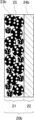
- FIG. 2 is a schematic cross-sectional view of a carbon dioxide reduction electrode catalyst layer suitably used in the present embodiment.
- FIG. 2 is a schematic cross-sectional view of a carbon dioxide reduction electrode catalyst layer suitably used in the present embodiment.
- FIG. 1 is a schematic diagram of a solid electrolyte electrolysis device suitably used in the present embodiment.
- the carbon dioxide reduction electrode catalyst layer according to the embodiment of the present disclosure contains a catalyst, alkali metal ions, and a polymer material capable of releasing alkali metal ions.
- the "catalyst layer for a carbon dioxide reduction electrode” may be simply referred to as the “catalyst layer.”
- the "polymer material capable of releasing alkali metal ions” may be simply referred to as the "polymer material according to an embodiment of the present disclosure.”
- an electrolyte particularly alkali metal ions as cationic species
- the ion exchange membrane allows the electrolyte to pass through, which can lead to problems such as excess moisture inside the catalyst layer and salt precipitation near the cathode, blocking the flow path.
- This phenomenon has adverse effects such as interfering with the supply of carbon dioxide to the cathode catalyst, making it easy to reduce the efficiency of electrolysis.
- the electrolyte is pure water, it reduces the stability of the intermediates in the carbon dioxide reduction reaction, making it easy to reduce the efficiency of electrolysis.
- the carbon dioxide reduction electrode catalyst layer according to the embodiment of the present disclosure has high electrolysis efficiency in the carbon dioxide electrolytic reduction reaction.
- the reason for this is unclear, it is believed that the coexistence of alkali metal ions and a polymer material capable of releasing alkali metal ions together with the catalyst in the catalyst layer stably supplies alkali metal ions to the intermediate generated in the carbon dioxide reduction reaction, thereby improving the electrolysis efficiency.
- the chemical interaction between the polymer material according to the embodiment of the present disclosure and the alkali metal ions inhibits the alkali metal ions from leaving the catalyst layer, thereby inhibiting their precipitation as salt near the cathode, thereby improving the electrolysis efficiency.
- the carbon dioxide reduction electrode catalyst layer according to the embodiment of the present disclosure is capable of controlling the concentration of alkali metal ions in the vicinity of the cathode to an extent that they do not precipitate as a salt while promoting the reduction reaction, and is therefore considered to be able to improve the electrolysis efficiency.
- the carbon dioxide reduction electrode catalyst layer, as well as the cathode, the ion exchange membrane-electrode assembly, and the solid electrolyte electrolysis device according to the embodiments of the present disclosure will be described in detail.
- FIG. 1 is a schematic cross-sectional view of an ion-exchange membrane-electrode assembly that is preferably used in this embodiment.
- FIG. 1 shows an ion-exchange membrane-electrode assembly 50 having a gas diffusion layer 10 , a carbon dioxide reduction electrode catalyst layer 20 , a solid electrolyte 30 , and an anode 40 .
- the catalyst layer 20 contains the catalyst 23 according to this embodiment, the alkali metal ions according to this embodiment, and the polymer material 24 according to this embodiment.
- the gas diffusion layer 10 and the catalyst layer 20 are combined to form the cathode according to this embodiment.
- carbon dioxide (CO 2 ) is supplied to a catalyst layer 20 through a gas diffusion layer 10, and carbon monoxide (CO) is produced by a reduction reaction.
- CO 2 carbon dioxide
- CO carbon monoxide
- the catalyst layer 20 according to the embodiment of the present disclosure may have a single-layer structure as shown in FIG. 2, or may have a laminated structure of two or more layers as shown in FIG.
- the catalyst layer 20a having a single layer structure shown in FIG. 2 contains a catalyst 23a according to this embodiment, an alkali metal ion according to this embodiment, and a polymer material 24a according to this embodiment.
- the catalyst layer 20b having a laminated structure shown in FIG. 3 has a reaction layer 21 containing the catalyst 23b according to this embodiment and a layer 22 (also referred to as a cation supply layer 22) containing the alkali metal ions according to this embodiment and the polymer material 24b according to this embodiment.
- the catalyst layer 20 contains a catalyst 23a, an alkali metal ion, and a polymer material 24 capable of releasing the alkali metal ion in the same layer. From the viewpoint of stably supplying alkali metal ions to the intermediate generated by the dioxidation-reduction reaction in the catalyst layer 20a, it is preferable that the catalyst 23a and the alkali metal ions are dispersed and integrated in a polymer material capable of releasing the alkali metal ions in the catalyst layer 20a.
- the alkali metal ions are unlikely to leave the catalyst layer due to chemical interaction between the polymer material according to this embodiment and the alkali metal ions, from the viewpoint of further suppressing the release of the alkali metal ions from the catalyst layer, it is preferable that a part of the polymer material according to this embodiment is substituted with an alkali metal ion.
- the alkali metal ions contained in the catalyst layer 20a and the polymer material 24a capable of releasing alkali metal ions are preferably polymer materials that are substituted with alkali metal ions and capable of releasing alkali metal ions.
- the alkali metal ions contained in the catalyst layer 20a and the polymer material 24a capable of releasing alkali metal ions will be described in detail later.
- the content of the catalyst 23a in the catalyst layer 20a is preferably 50 to 99 mass%, more preferably 75 to 97 mass%, and even more preferably 90 to 95 mass%, from the viewpoint of further improving the electrolytic activity and the CO2 reduction reaction rate.
- the content of the polymer material capable of releasing alkali metal ions in the catalyst layer 20a is preferably 1 to 50 mass%, more preferably 1 to 30 mass%, and even more preferably 2 to 20 mass%, from the viewpoint of further improving the electrolytic activity and the CO2 reduction reaction rate.
- the content of alkali metal ions in the catalyst layer 20a is preferably 0.01 to 20 mass%, more preferably 0.01 to 10 mass%, and further preferably 0.1 to 5 mass%.
- the content of alkali metal ions in the catalyst layer 20a can be measured by X-ray photoelectron spectroscopy.
- the catalyst layer 20 may have different components contained in different layers, such as a two-layer structure of a layer containing a catalyst and a layer containing alkali metal ions and a polymeric material capable of releasing alkali metal ions, or a three-layer structure of a layer containing a catalyst, a layer containing alkali metal ions, and a layer containing a polymeric material capable of releasing alkali metal ions, etc.
- two or more layers of the same layer may be laminated, such as a four-layer structure in which a layer containing a catalyst/a layer containing alkali metal ions and a polymeric material capable of releasing alkali metal ions are alternately laminated.
- FIG. 3 shows, as an example of a laminated structure, a catalyst layer 20b having a two-layer structure including a reaction layer 21 containing a catalyst 23b and a cation supply layer 22 containing alkali metal ions and a polymer material 24b capable of releasing alkali metal ions.
- the reaction layer 21 functions as a layer that promotes a carbon dioxide reduction reaction in the presence of the catalyst 23 b
- the cation supply layer 22 functions as a layer that supplies alkali metal ions to the reaction layer 21 .
- the catalyst layer having a laminated structure preferably has a reaction layer 21 containing a catalyst 23b and a layer 22 (cation supply layer 22) containing alkali metal ions and a polymer material 24b capable of releasing alkali metal ions, as shown in FIG. 3.
- a reaction layer 21 containing a catalyst 23b and a layer 22 (cation supply layer 22) containing alkali metal ions and a polymer material 24b capable of releasing alkali metal ions, as shown in FIG. 3.
- the reaction layer 21 and the cation supply layer 22 are provided integrally. In other words, it is preferable that the reaction layer 21 and the cation supply layer 22 are adjacent to each other. In addition, it is preferable that the catalyst layer 20 b be arranged so that the reaction layer 21 is adjacent to the gas diffusion layer 10 and the cation supply layer 22 is adjacent to the solid electrolyte 30 .
- the reaction layer 21 includes a catalyst 23b.
- the catalyst 23b may be the same as the catalyst 23a, and will be described in detail later.
- the catalyst 23b is dispersed in a dispersion medium 25.
- the dispersion medium 25 is not particularly limited as long as it is a medium capable of dispersing the catalyst 23b, and for example, an ionomer can be used. The details of the ionomer will be described later.
- the reaction layer 21 may or may not contain alkali metal ions, but since the catalyst layer 20b has the cation supply layer 22, the content of alkali metal ions in the reaction layer 21 can be 0 mass %.
- the content of the catalyst 23b in the reaction layer 21 is preferably 50 to 99 mass%, more preferably 75 to 97 mass%, and even more preferably 90 to 95 mass%, from the viewpoint of further improving the electrolytic activity and the reduction reaction rate of CO2.
- the content of the polymer material capable of releasing alkali metal ions in the cation supply layer 22 is preferably 5 to 99 mass%, more preferably 10 to 95 mass%, and even more preferably 20 to 95 mass%, from the viewpoint of further improving the electrolytic activity and the reduction reaction rate of CO2.
- the cation supply layer 22 preferably has a layer thickness of 0.005 to 0.5 mm.
- a layer thickness of 0.005 to 0.5 mm Each component contained in the catalyst layer will be described below. In the following description, the reference symbols in Figs. 1 to 3 will be omitted.
- Alkali metal ions examples include a lithium ion (Li + ), a sodium ion (Na + ), a potassium ion (K + ), a rubidium ion (Rb + ), and a cesium ion (Cs + ).
- the amount of ions supplied to the intermediate generated by carbon dioxide reduction reactivity varies depending on the adsorption force between the polymer material capable of releasing alkali metal ions and the alkali metal ions.
- the adsorption force for alkali metal ions increases in the order Li + ⁇ Na + ⁇ K + ⁇ Rb + .... It is preferable to control the adsorption force so that the amount of alkali metal ions supplied to the intermediate is sufficient while avoiding excessive supply, which would result in salt precipitation.
- the adsorptive strength differs depending on the combination of the alkali metal ion and the polymer material of this embodiment, but the alkali metal ion is preferably one or more selected from the group consisting of potassium ions, sodium ions, rubidium ions, and cesium ions, and more preferably one or more selected from the group consisting of potassium ions, rubidium ions, and cesium ions.
- the alkali metal ions may be used alone or in combination of two or more.
- Polymer material capable of releasing alkali metal ions As the polymer material capable of releasing alkali metal ions, an ionomer, a polymer gel, or the like can be used.
- the polymer material according to the present embodiment may be used alone or in combination of two or more.
- an ionomer can be used as a dispersion medium in the reaction layer in the catalyst layer having a laminated structure.
- the ionomer functions as a binder resin in a catalyst layer having a single layer structure or in a reaction layer in a catalyst layer having a laminated structure, and is a matrix resin (continuous phase) capable of dispersing and immobilizing the catalyst according to the present embodiment, and also has a function of transmitting ions generated by electrolysis and improving the efficiency of CO2 electrolysis.
- the ionomer is preferably conductive from the viewpoint of improving the transmission efficiency of ions generated by electrolysis, and is more preferably a polymer electrolyte.
- the polymer electrolyte is further preferably an ion exchange resin.
- the ion exchange resin may be a cation exchange resin or an anion exchange resin.
- Examples of the cation exchange resin include fluororesins having sulfonic groups and styrene-divinylbenzene copolymers having sulfonic groups. Commercially available products can also be used, such as Nafion (manufactured by Chemours), Aquivion (manufactured by Solvay Specialty Polymers), DIAION (manufactured by Mitsubishi Chemical Corporation), and Fumasep (manufactured by FUMATECH).
- Examples of anion exchange resins include resins having one or more ion exchange groups selected from the group consisting of quaternary ammonium groups, primary amino groups, secondary amino groups, and tertiary amino groups.
- Sustainion manufactured by Dioxide Materials
- Fumasep manufactured by FUMATECH
- PENTION manufactured by Xergy
- DURION manufactured by Xergy
- NEOSEPTA manufactured by Astom
- TOYOPEARL manufactured by Tosoh
- the anion exchange resin preferably has a basic site density in a dry state of 2.0 to 5.0 mmol/ cm3 , more preferably 2.5 mmol/ cm3 or more and less than 4.5 mmol/ cm3 , and even more preferably 2.9 mmol/ cm3 or more and less than 4.5 mmol/ cm3 .
- the basic site density of the anion exchange resin can be obtained from the signal integral value when 1 H NMR measurement is performed on the anion exchange resin.
- a dry state means that the anion exchange resin does not contain free water; for example, the anion exchange resin can be brought into a dry state by heating in a vacuum.
- Polymer gel From the viewpoint of encapsulating and releasing alkali metal ions and ensuring ionic conductivity, it is preferable to use a polymer gel that has water retention and hydrophilicity.
- polyacrylamide, agarose, starch, gelatin, etc. can be used as the polymer gel that has water retention and hydrophilicity.
- the polymer gel is preferably polyacrylamide, gelatin, and agarose, and more preferably polyacrylamide and agarose.
- the polymer material capable of releasing alkali metal ions preferably contains an ionomer, and more preferably contains a cation exchange resin, from the viewpoint of easily supplying alkali metal ions to the intermediate generated in the carbon dioxide reduction reaction and suppressing their release from the catalyst layer.
- the "alkali metal ions and the polymer material capable of releasing alkali metal ions” contains a cation exchange resin substituted with alkali metal ions.
- a cation exchange resin substituted with alkali metal ions.
- the method for substituting the alkali metal ions on the cation exchange resin is not particularly limited.
- a solution of a cation exchange resin dissolved in a solvent such as ethanol is applied onto a substrate, dried, and then the substrate is immersed in an aqueous solution of an inorganic salt such as a carbonate or hydrogen carbonate containing 0.01 to 5 mol/L of an alkali metal species.
- the aqueous solution of the inorganic salt in which the substrate is immersed is placed in a reduced pressure environment, and after removing any remaining air bubbles, the solution is allowed to stand for one hour or more, thereby performing metal ion replacement on the cation exchange resin.
- the polymer material capable of releasing alkali metal ions contained in the cation supply layer preferably contains a polymer gel
- the "alkali metal ions and the polymer material capable of releasing alkali metal ions” preferably contains a polymer gel containing an aqueous solution containing an alkali metal salt.
- the aqueous solution containing an alkali metal salt include aqueous solutions containing the same components as the electrolyte, and specific examples include aqueous solutions of KHCO3 , NaHCO3 , Cs2CO3 , etc.
- the dispersion medium contained in the reaction layer is preferably an ionomer, and the catalyst is preferably coated with the ionomer.
- the catalyst is preferably coated with the ionomer.
- the catalyst according to the embodiment of the present disclosure is not particularly limited as long as it is a catalyst that promotes a carbon dioxide reduction reaction.
- the catalyst preferably includes one or more selected from the group consisting of the following catalyst A and the following catalyst B.
- catalyst A has metal ions selected from the group consisting of copper ions, nickel ions, iron ions, cobalt ions, zinc ions, manganese ions, molybdenum ions, and aluminum ions, a nitrogen-containing compound, and a carbon-containing support.
- Catalyst B has inorganic fine particles selected from the group consisting of gold, silver, copper, nickel, iron, cobalt, zinc, chromium, palladium, tin, manganese, aluminum, indium, bismuth, molybdenum, and carbon nitride; or a metal complex in which a ligand is coordinated to an ion of a metal selected from the group consisting of copper, nickel, iron, cobalt, zinc, manganese, molybdenum, and aluminum, and a carbon-containing support.
- the component exhibiting catalytic activity in the reduction reaction of carbon dioxide is the above-mentioned metal ion, and in the technology of the present disclosure, a configuration having a metal ion coordinated to a nitrogen atom on a nitrogen-containing compound and a carbon-containing support is referred to as a "catalyst".
- the component that exhibits catalytic activity in the reduction reaction of carbon dioxide is the inorganic fine particles or the metal complex, but in the technology of the present disclosure, the inorganic fine particles or the metal complex are referred to as the "catalyst source", and a configuration having the catalyst source and the carbon-containing carrier is referred to as the "catalyst”.
- Catalyst source (metal ion) of catalyst A contains, as a catalyst source, metal ions selected from the group consisting of copper ions, nickel ions, iron ions, cobalt ions, zinc ions, manganese ions, molybdenum ions, and aluminum ions.
- the metal ions in this embodiment have the effect of producing at least carbon monoxide through a reduction reaction.
- the metal ion is preferably present in a monoatomic state and supported on the carbon-containing support according to the present embodiment.
- the catalyst source By making the catalyst source exist in a monoatomic state, activity can be increased.
- gold and silver are widely used as catalyst sources. However, since they are rare and expensive, it is preferable to use a catalyst in place of gold and silver in which ions of a metal other than gold and silver are coordinated to nitrogen atoms and supported on a carbon-containing monomer.
- the metal of the metal ion in this embodiment is selected from the group consisting of copper, nickel, iron, cobalt, zinc, manganese, molybdenum, and aluminum.
- the metal of the metal ion is preferably nickel, cobalt, iron, copper, zinc, or manganese, more preferably nickel, cobalt, iron, or copper, and further preferably nickel, cobalt, or iron.
- the catalyst A according to the present embodiment may contain only one type of metal ion, or may contain two or more types of metal ions.
- the content of metal ions in catalyst A is preferably less than 50 mass %.
- the content of metal ions coordinated to nitrogen atoms in catalyst A is more preferably 0.8 to 15 mass %, and further preferably 0.9 to 10 mass %.
- the active site density means the content (mass %) of metal ions coordinated to nitrogen atoms of the nitrogen-containing compound in the catalyst A.
- the content of metal ions coordinated to nitrogen atoms can be determined as follows.
- the content ratio of metal ions bound (coordinated) to nitrogen atoms and metal fine particles in catalyst A can be measured by X-ray absorption fine structure analysis (XAFS).
- XAFS X-ray absorption fine structure analysis
- XRF X-ray fluorescence analysis
- the content of metal ions coordinated to nitrogen atoms can be calculated from the results of XAFS and XRF measurements.
- the content of Ni ions coordinated to nitrogen atoms can be calculated by multiplying the total Ni content, including Ni metal and Ni ions, measured by XRF by the proportion of Ni ions in the total Ni determined by XAFS.
- the metal particles do not act as active sites, and the metal exists in the form of agglomerates.
- the nitrogen-containing compound contained in catalyst A is not particularly limited, and examples thereof include pentaethylenehexamine, tetraethylenepentamine, triethylenepentamine, diethylenetriamine, ethylenediamine, diethylamine, and the like. From the viewpoint of improving electrolytic activity, pentaethylenehexamine, tetraethylenepentamine, and triethylenepentamine are preferred, and pentaethylenehexamine and tetraethylenepentamine are more preferred.
- the content of the nitrogen-containing compound in the catalyst A according to this embodiment is preferably 5 to 75 mass %, more preferably 10 to 60 mass %, and even more preferably 20 to 50 mass %, from the viewpoint of improving the active site density.
- Catalyst source for catalyst B (inorganic fine particles, metal complex)
- the catalyst B according to this embodiment has inorganic fine particles or a metal complex as a catalyst source.
- the inorganic fine particles and the metal complex in this embodiment have the effect of producing at least carbon monoxide through a reduction reaction.
- the inorganic fine particles in this embodiment are inorganic fine particles selected from the group consisting of gold, silver, copper, nickel, iron, cobalt, zinc, chromium, palladium, tin, manganese, aluminum, indium, bismuth, molybdenum, and carbon nitride, and may be used alone or in combination of two or more.
- the material of the inorganic fine particles is preferably silver, gold, zinc, tin, copper and bismuth, more preferably silver, gold, copper and tin, and even more preferably silver, gold and copper.
- the average particle size of the inorganic fine particles as the catalyst source is preferably 65 nm or less, more preferably 60 nm or less, more preferably 50 nm or less, more preferably 40 nm or less, and more preferably 30 nm or less, from the viewpoint of the reaction rate of the carbon dioxide reduction reaction.
- the average particle size can be measured by photographic observation using a scanning electron microscope or the like.
- the metal complex in this embodiment is a metal complex in which a ligand is coordinated to a metal or an ion of the metal, and the metal here is selected from the group consisting of copper, nickel, iron, cobalt, zinc, manganese, molybdenum, and aluminum.
- the metal is preferably nickel, cobalt, iron, copper, zinc, or manganese, more preferably nickel, cobalt, iron, or copper, and further preferably nickel, cobalt, or iron.
- the metal complex may contain only one type of metal or ion of the metal, or may contain two or more types of metals.
- the type of the ligand is not particularly limited, and examples thereof include phthalocyanine complexes, porphyrin complexes, pyridine complexes, metal-supported covalent triazine structures, and metal organic structures. Among these, phthalocyanine complexes, porphyrin complexes, pyridine complexes, and metal-supported covalent triazine structures are preferred, phthalocyanine complexes, porphyrin complexes, and metal-supported covalent triazine structures are more preferred, and porphyrin complexes and metal-supported covalent triazine structures are even more preferred.
- the metal complex may contain only one type of ligand, or may contain two or more types.
- Carbon-containing support Catalyst A and Catalyst B each independently contain a carbon-containing support. Since carbon generally has electrical conductivity, the carbon-containing support according to this embodiment is an electrically conductive support.
- the carbon-containing support according to this embodiment is not limited as long as it is a conductive material that can be used as a gas diffusion layer in an electrode provided in an apparatus for reducing carbon dioxide, and examples of the carbon-containing support include carbon black (furnace black, acetylene black, ketjen black, medium thermal carbon black, etc.), activated carbon, graphite, carbon nanotubes, carbon nanofibers, carbon nanohorns, graphene nanoplatelets, nanoporous carbon, and the like. Among these, carbon black is preferred from the viewpoint of improving the active site density.
- the primary particle diameter of the carbon black is preferably 10 to 100 nm, and more preferably 10 to 50 nm.
- the primary particle diameter of the carbon black can be measured by a transmission electron microscope. From the same viewpoint, it is preferable that the secondary particle size (particle size of aggregates) of the carbon black is small, and it is preferable that the carbon black has a large amount of functional groups.
- the carbon black may be a commercially available product, and examples thereof include Vulcan (registered trademark) XC-72 (manufactured by Cabot Corporation) and BLACK PEARL 2000 (manufactured by Cabot Corporation).
- the catalysts according to this embodiment preferably have a particle size of 10 nm to 50 ⁇ m.
- the catalyst particle size is 50 ⁇ m or less, the active site density is increased, and the reduction reaction rate of CO 2 can be improved.
- the catalyst particle size is 10 nm or more, precipitation of electrolyte salt from the solid electrolyte can be suppressed, and the workability is excellent.
- the particle size of the catalyst is preferably 20 nm to 40 ⁇ m, and more preferably 30 nm to 20 ⁇ m.
- the particle size of the catalyst can be confirmed by a laser diffraction/scattering type particle size distribution measuring device.
- the method for producing the catalyst according to this embodiment is not particularly limited.
- the method for producing catalyst A may, for example, include a mixing step of mixing metal ions, a nitrogen-containing compound, and a carbon-containing support to obtain a mixture, and a calcination step of calcining the mixture to obtain a calcined product.
- the method for producing catalyst A may further include a washing step of washing the calcined product, a crushing step of crushing the calcined product, etc.
- catalyst B can be produced by supporting inorganic fine particles and a metal complex, which are catalyst sources, on a carbon-containing support by a known method such as vapor deposition, precipitation, adsorption, deposition, adhesion, welding, physical mixing, spraying, or the like.
- the cathode (negative electrode) according to this embodiment has the carbon dioxide reduction electrode catalyst layer according to this embodiment described above, and a gas diffusion layer.
- the cathode according to this embodiment has high electrolysis efficiency by virtue of being provided with the catalyst layer according to this embodiment.
- the gas diffusion layer includes, for example, carbon paper or nonwoven fabric, or a metal mesh, such as graphite carbon, glassy carbon, titanium, or SUS steel.
- the ion exchange membrane-electrode assembly according to this embodiment has the cathode according to the embodiment described above, a solid electrolyte, and an anode.
- the ion exchange membrane-electrode assembly according to this embodiment has a cathode including the catalyst layer according to this embodiment, and therefore has high electrolysis efficiency.
- the ion exchange membrane-electrode assembly has a solid electrolyte.
- the solid electrolyte may be a polymer membrane.
- the polymer may be any of various ionomers, and may be either a cation exchange resin or an anion exchange resin, but is preferably an anion exchange resin. That is, the solid electrolyte is preferably an anion exchange membrane.
- the solid electrolyte may be a commercially available product such as a cation exchange membrane or an anion exchange membrane.
- the base site density in a dry state is preferably 0.5 to 5.0 mmol/ cm3 , more preferably 2.5 mmol/ cm3 or more and less than 4.5 mmol/ cm3 , and even more preferably 2.9 mmol/ cm3 or more and less than 4.5 mmol/ cm3 .
- cation exchange membrane for example, strongly acidic cation exchange membranes in which sulfonic groups have been introduced into a fluororesin matrix, such as Nafion 117, Nafion 115, Nafion 212, and Nafion 350 (manufactured by Chemrous Corporation), and strongly acidic cation exchange membranes in which sulfonic groups have been introduced into a styrene-divinylbenzene copolymer matrix, such as NeoSepta CSE (manufactured by Astom Corporation), can be used.
- a fluororesin matrix such as Nafion 117, Nafion 115, Nafion 212, and Nafion 350
- NeoSepta CSE manufactured by Astom Corporation
- anion exchange membranes include anion exchange membranes having one or more ion exchange groups selected from the group consisting of quaternary ammonium groups, primary amino groups, secondary amino groups, and tertiary amino groups. Specific examples include Neocepta (registered trademark) ASE, AHA, ACS, AFX (manufactured by Astom Corporation), Selemion (registered trademark) AMVN, DSVN, AAV, ASVN, AHO (manufactured by Asahi Glass Co., Ltd.), etc.
- the reduction reaction of carbon dioxide at the cathode in this embodiment differs depending on the type of solid electrolyte.
- a cation exchange membrane is used as the solid electrolyte
- the reduction reactions shown in the following reaction formulas (1) and (2) occur
- an anion exchange membrane is used as the solid electrolyte
- the reduction reactions shown in the following reaction formulas (3) and (4) occur.
- the oxidation reaction at the anode varies depending on the type of solid electrolyte.
- a cation exchange membrane is used as the solid electrolyte
- the oxidation reaction shown in the following reaction formula (5) occurs
- an anion exchange membrane is used as the solid electrolyte
- the oxidation reaction shown in the following reaction formula (6) occurs.
- the anode is a gas diffusion electrode that includes a gas diffusion layer.
- the gas diffusion layer includes, for example, a metal mesh.
- the electrode material of the anode include Ir, IrO2 , Ru, RuO2 , Co, CoOx, Cu, CuOx, Fe, FeOx, FeOOH, FeMn, Ni, NiOx, NiOOH, NiCo, NiCe, NiC, NiFe, NiCeCoCe, NiLa, NiMoFe, NiSn, NiZn, SUS, Au, and Pt.
- the solid electrolyte electrolysis device includes the cathode according to the embodiment described above, an anode that constitutes a pair of electrodes together with the cathode, a solid electrolyte that is interposed between the cathode and the anode in contact with each other, and a voltage application unit that applies a voltage between the cathode and the anode.
- the solid electrolyte electrolysis device has a cathode (negative electrode) including the catalyst layer according to this embodiment, and therefore has high electrolysis efficiency.
- FIG. 4 is a schematic diagram of a solid electrolyte electrolysis device preferably used in this embodiment.
- FIG. 4 shows a solid electrolyte electrolysis device 800 having a cathode (negative electrode) 200 according to this embodiment, an anode (positive electrode) 400 constituting a pair of electrodes together with the cathode 200, a solid electrolyte 300 interposed in contact between the cathode 200 and the anode 400, and a voltage application unit 700 that applies a voltage between the cathode 200 and the anode 400.
- the solid electrolyte electrolysis device 800 shown in FIG. 4 further includes a cathode current collector 100 , an anode current collector 500 , and an electrolyte solution 600 .
- the cathode according to the present embodiment described above is used as the cathode 200.
- the solid electrolyte 300 is the same as the solid electrolyte 30 in Fig. 1, and the solid electrolyte 300 is preferably an anion exchange membrane.
- the anode 400 is the same as the anode 40 in Fig. 1.
- the details of the cathode 200, the solid electrolyte 300, and the anode 400 are as described above. In the following description, the reference numerals of each element other than the cathode 200, the solid electrolyte 300, and the anode 400 will be omitted.
- Examples of the cathode current collector include metal materials such as copper (Cu), nickel (Ni), stainless steel (SUS), nickel-plated steel, and brass, among which copper is preferred from the viewpoints of ease of processing and cost.
- examples of the shape of the cathode current collector include metal foil, metal plate, metal thin film, expanded metal, punched metal, and foamed metal.
- the cathode current collector may be provided with a gas supply hole for supplying a raw material gas containing carbon dioxide to the cathode and a gas recovery hole for recovering a generated gas containing carbon monoxide.
- the raw material gas can be uniformly and efficiently fed to the cathode and the generated gas (including unreacted raw material gas) can be discharged.
- the gas supply hole and the gas recovery hole may be provided independently of each other, either alone or in combination of two or more.
- the shape, location, size, etc. of the gas supply hole and the gas recovery hole are not limited and are appropriately set.
- the cathode current collector is permeable, the gas supply hole and the gas recovery hole are not necessarily required.
- the cathode current collector is not necessarily required.
- the anode current collector preferably has electrical conductivity to receive electrons from the anode and has rigidity to support the anode.
- the anode current collector can be made of a metal material such as titanium (Ti), copper (Cu), nickel (Ni), stainless steel (SUS), nickel-plated steel, or brass.
- the anode current collector may be provided with a gas flow path for feeding a raw material gas (H 2 O, etc.) to the anode.
- a raw material gas H 2 O, etc.
- the gas flow path in the anode current collector the raw material gas can be fed uniformly and efficiently to the anode.
- the number, shape, location, size, etc. of the gas flow path are not limited and may be set appropriately.
- the voltage application unit applies a voltage between the cathode and the anode by applying a voltage to the cathode current collector and the anode current collector. Since both current collectors are conductors, they supply electrons to the cathode and receive electrons from the anode.
- a control unit (not shown) may be electrically connected to the voltage application unit to apply an appropriate voltage.
- Examples of the electrolyte include pure water and an aqueous solution of an electrolyte.
- Examples of the aqueous solution of an electrolyte include an aqueous solution of a carbonate, an aqueous solution of a hydrogen carbonate (e.g., an aqueous solution of KHCO3 ), an aqueous solution of a sulfate, an aqueous solution of a borate, an aqueous solution of a sodium hydroxide, an aqueous solution of potassium hydroxide, and an aqueous solution of sodium chloride.
- the aqueous solution preferably has a pH of 5 or higher.
- the concentration of the electrolyte such as the carbonate or hydrogen carbonate in the electrolytic solution is preferably less than 0.1 mol/L.
- the solid electrolyte electrolysis device preferably has an electrolyte in contact with the anode, and the electrolyte is preferably pure water.
- reaction gas supply unit In the solid electrolyte electrolysis device according to this embodiment, a reaction gas supply unit (not shown) may be provided outside the solid electrolyte electrolysis device. That is, as long as the reaction gas CO 2 is supplied to the catalyst layer of the cathode, the reaction gas may be supplied from the reaction gas supply unit to the gas supply hole via a pipe (not shown), or the reaction gas may be sprayed onto the surface of the cathode current collector opposite to the contact surface with the cathode. From an environmental point of view, it is preferable to use factory exhaust gas discharged from a factory as the reaction gas.
- CO2 which is a reactant gas serving as a raw material
- a reactant gas supply unit not shown
- CO2 is supplied to the cathode, for example, through a gas supply hole provided in the cathode current collector.
- the CO2 supplied to the cathode comes into contact with the catalyst layer of the cathode, and when a cation exchange membrane is used as the solid electrolyte, the reduction reactions of the above-mentioned reaction formulas (1) and (2) occur, and when an anion exchange membrane is used as the solid electrolyte, the reduction reactions of the above-mentioned reaction formulas (3) and (4) occur, thereby producing a synthesis gas containing at least CO and H2 .
- the synthesis gas containing the generated CO and H2 is sent to a gas recovery device (not shown), for example, through a gas recovery hole provided in the cathode current collector, and is recovered in predetermined gas fractions.
- the obtained mixture was heated in an inert gas using a calcination furnace at 900° C. for 10 seconds or more and calcined. Thereafter, the product was washed with an aqueous sulfuric acid solution, and the solid matter was collected using a suction filter. Furthermore, the solid matter was vacuum dried at 60° C. overnight to obtain a catalyst powder (intermediate) supported with a Ni complex.
- the primary particle size of the carbon black was determined by laser diffraction particle size distribution measurement.
- 0.3 g of the obtained catalyst powder was placed in a pot together with 10 g of zirconia balls with a diameter of 0.5 mm and 10 mL of water, and pulverized for 20 minutes at a rotation speed of 800 rpm using a planetary ball mill device to recover a catalyst slurry.
- the slurry was washed again with an aqueous sulfuric acid solution, and the solid matter was recovered using a suction filter.
- the solid matter was vacuum-dried overnight at 60°C to obtain the final catalyst powder (catalyst A according to this embodiment).
- the cathode precursor was immersed in a 2 mol/L potassium bicarbonate aqueous solution. With the cathode precursor immersed, the aqueous solution was left to stand for 10 minutes in a vacuum chamber in a reduced pressure environment of 10 kPa (absolute pressure) to remove remaining air bubbles inside the cathode precursor. Thereafter, the solution was left to stand for 12 hours or more to perform metal ion substitution on the cation exchange resin, thereby obtaining a cathode (negative electrode) equipped with a single-layered catalyst layer containing the cation exchange resin substituted with alkali metal ions.
- the cathode has a coating film of the dispersion as a catalyst layer and carbon paper as a gas diffusion layer.
- Example 2 A solid electrolyte electrolytic device of Example 2 was manufactured in the same manner as in Example 1, except that the electrolyte was changed to a 0.01 mol/L KHCO3 aqueous solution.
- Example 3 A solid electrolyte electrolysis device of Example 3 was produced in the same manner as in Example 1, except that in the production of the solid electrolyte electrolysis device of Example 1, the cathode precursor was immersed in a 2 mol/L aqueous solution of rubidium carbonate instead of the aqueous solution of potassium hydrogen carbonate.
- Example 4 A solid electrolyte electrolytic device of Example 4 was manufactured in the same manner as in Example 1, except that the electrolyte was changed to a 0.1 mol/L KHCO3 aqueous solution.
- Comparative Example 1 A solid electrolyte electrolysis device of Comparative Example 1 was produced in the same manner as in Example 1, except that in the production of the solid electrolyte electrolysis device of Example 1, the cathode precursor was not substituted with an alkali metal ion, and the cathode precursor was used as a cathode.
- Comparative Example 2 A solid electrolyte electrolytic device of Comparative Example 2 was manufactured in the same manner as in Comparative Example 1, except that the electrolytic solution was a 0.01 mol/L KHCO3 aqueous solution.
- Example 5 [Catalyst Production] In a beaker, 100 mL of ethanol was mixed with 0.1 g of carbon black (carbon-containing carrier according to this embodiment) having a primary particle diameter of 30 nm, and the obtained ethanol dispersion was irradiated with ultrasonic waves for 10 minutes. Then, the dispersion was left to stand in a vacuum chamber in a reduced pressure environment of 10 kPa (absolute pressure) for 10 minutes. Then, 11.7 mL of 0.1 mol/L AgNO3 solution and 1 mL of 2.3 mol/L sodium phosphinate solution were mixed and stirred at 15 ° C for 16 hours to reduce silver nitrate.
- carbon black carbon-containing carrier according to this embodiment
- the obtained slurry was washed with distilled water, the solid matter was collected by a centrifuge, and the solid matter was vacuum dried at 60 ° C overnight to obtain a catalyst powder (catalyst B according to this embodiment) supported with Ag particles.
- the obtained catalyst was carbon black supporting Ag particles as a catalyst source, and the mass of the supported Ag particles was 40 parts by mass per 100 parts by mass of carbon black not supporting Ag particles.
- the primary particle size of the carbon black was determined by laser diffraction particle size distribution measurement.
- the cathode precursor was immersed in a 2 mol/L potassium bicarbonate aqueous solution. With the cathode precursor immersed, the aqueous solution was left to stand for 10 minutes in a vacuum chamber in a reduced pressure environment of 10 kPa (absolute pressure) to remove remaining air bubbles inside the cathode precursor. Thereafter, the solution was left to stand for 12 hours or more to perform metal ion substitution on the cation exchange resin, thereby obtaining a cathode (negative electrode) equipped with a single-layered catalyst layer containing the cation exchange resin substituted with alkali metal ions.
- the cathode has a coating film of the dispersion as a catalyst layer and carbon paper as a gas diffusion layer.
- Comparative Example 3 A solid electrolyte electrolysis device of Comparative Example 3 was produced in the same manner as in Example 5, except that in the production of the solid electrolyte electrolysis device of Example 5, the cathode precursor was not substituted with alkali metal ions, and the cathode precursor was used as the cathode.
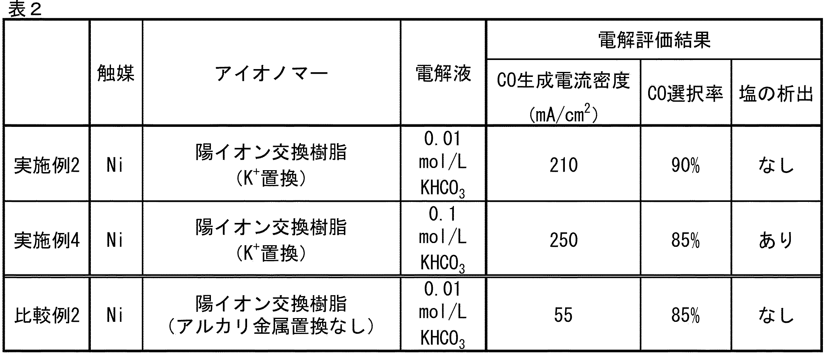
- Example 1 The results of the systems in which the catalyst species was Ni and the electrolyte was pure water (Example 1, Example 3, and Comparative Example 1) are shown in Table 1; the results of the systems in which the catalyst species was Ni and the electrolyte was an aqueous potassium hydrogen carbonate solution (Example 2, Example 4, and Comparative Example 2) are shown in Table 2; and the results of the systems in which the catalyst species was Ag and the electrolyte was pure water (Example 5 and Comparative Example 3) are shown in Table 3.
- Example 6 [Production of cathode] Potassium hydrogen carbonate was mixed into a 0.2 g/L aqueous agarose solution heated to 90° C. to a concentration of 0.5 mol/L, and then cooled to obtain a gel-like solid. The obtained solid was pulverized in an agate mortar and applied to the dispersion-coated film side surface of the cathode precursor produced in Example 1 in an amount of 50 mg/ cm2 to form a gel-coated film, which was used as the cathode.
- the cathode (negative electrode) has a cathode precursor dispersion coating film as a reaction layer in the catalyst layer, a gel coating film as a cation supply layer in the catalyst layer, and carbon paper as a gas diffusion layer.
- Example 7 A solid electrolyte electrolysis device of Example 7 was manufactured in the same manner as in Example 6, except that in the manufacturing process of the solid electrolyte electrolysis device of Example 6, potassium hydrogen carbonate was changed to sodium hydrogen carbonate in the formation of the gel coating film.
- Example 8 A solid electrolyte electrolysis device of Example 8 was manufactured in the same manner as in Example 6, except that in the manufacturing process of the solid electrolyte electrolysis device of Example 6, potassium hydrogen carbonate was replaced with cesium carbonate in the formation of the gel coating film.
- Comparative Example 4 A solid electrolyte electrolysis device of Comparative Example 4 was produced in the same manner as in Example 6, except that the potassium hydrogen carbonate salt used in forming the gel coating film was not mixed in.
- Example 9 [Production of cathode]
- 100 mL of ethanol was mixed with 0.1 g of carbon black (carbon-containing carrier according to this embodiment) having a primary particle diameter of 30 nm, and the obtained ethanol dispersion was irradiated with ultrasonic waves for 10 minutes. Then, the dispersion was left to stand in a vacuum chamber in a reduced pressure environment of 10 kPa (absolute pressure) for 10 minutes. Then, 11.7 mL of 0.1 mol/L AgNO3 solution and 1 mL of 2.3 mol/L sodium phosphinate solution were mixed and stirred at 15 ° C for 16 hours to reduce silver nitrate.
- carbon black carbon-containing carrier according to this embodiment
- the obtained slurry was washed with distilled water, the solid matter was collected by a centrifuge, and the solid matter was vacuum dried at 60 ° C overnight to obtain a catalyst powder (catalyst B according to this embodiment) supported with Ag particles.
- the obtained catalyst was carbon black supporting Ag particles as a catalyst source, and the mass of the supported Ag particles was 40 parts by mass per 100 parts by mass of carbon black not supporting Ag particles.
- the primary particle size of the carbon black was determined by laser diffraction particle size distribution measurement.
- Cesium carbonate was mixed into a 0.2 g/L aqueous agarose solution heated to 90° C. to a concentration of 0.5 mol/L, and then cooled to obtain a gel-like solid.
- the resulting solid was pulverized in an agate mortar and applied to the dispersion-coated film side surface of the produced cathode precursor in an amount of 50 mg/ cm2 to form a gel-coated film, which was used as the cathode.
- the cathode (negative electrode) has a cathode precursor dispersion coating film as a reaction layer in the catalyst layer, a gel coating film as a cation supply layer in the catalyst layer, and carbon paper as a gas diffusion layer.
- Comparative Example 5 A solid electrolyte electrolytic device of Comparative Example 5 was produced in the same manner as in Example 9, except that in the production process of the solid electrolyte electrolytic device of Example 9, cesium carbonate salt was not mixed in the formation of the gel coating film.
- CO2 gas discharged from a factory is used as a raw material for the solid electrolyte electrolysis device, and renewable energy such as a solar cell is used for the voltage application unit, thereby generating a synthesis gas containing at least CO and H2 in a desired generation ratio.
- the synthesis gas thus generated can be used to generate fuel base stocks, chemical raw materials, etc., by methods such as Fischer-Tropsch synthesis (FT synthesis) and methanation.
- FT synthesis Fischer-Tropsch synthesis
Landscapes
- Chemical & Material Sciences (AREA)
- Engineering & Computer Science (AREA)
- Chemical Kinetics & Catalysis (AREA)
- Electrochemistry (AREA)
- Materials Engineering (AREA)
- Metallurgy (AREA)
- Organic Chemistry (AREA)
- Inorganic Chemistry (AREA)
- Electrolytic Production Of Non-Metals, Compounds, Apparatuses Therefor (AREA)
- Catalysts (AREA)
- Electrodes For Compound Or Non-Metal Manufacture (AREA)
Abstract
Description
酸化炭素還元反応の中間体は、安定性が比較的低いものの、アルカリ金属イオンと一時的に結合形成することで十分安定化することが知られている。非特許文献3に開示された手法は、アルカリ金属イオンを用いないことによる塩の析出抑制と、アルカリ金属イオンを用いることによる中間体安定との相反する要求を解消しそうであるが、当該手法では、セルの稼働率が低下する他、金属イオンを触媒近傍に留める機構が無く安定性が不十分という課題があった
<4> 前記触媒を含む反応層と、前記アルカリ金属イオン及び前記アルカリ金属イオンを放出可能な高分子材を含む層とが一体に設けられる<3>に記載の二酸化炭素還元電極用触媒層。
<10> 前記固体電解質が、陰イオン交換膜である<9>に記載のイオン交換膜-電極接合体。
前記カソードと一対の電極を構成するアノードと、
前記カソードと前記アノードとの間に接触状態にて介在する固体電解質と、
前記カソードと前記アノードとの間に電圧を印加する電圧印加部と
を有する固体電解質形電解装置。
<12> 更に、前記アノードに接する電解液を有し、前記電解液が純水である<11>に記載の固体電解質形電解装置。
<13> 前記固体電解質が、陰イオン交換膜である<11>又は<12>に記載の固体電解質形電解装置。
また、本明細書に記載された数値範囲「下限値~上限値」は、特に断りのない限り、下限値以上、上限値以下であることを意味する。
本開示の実施形態に係る二酸化炭素還元電極用触媒層は、触媒と、アルカリ金属イオンと、アルカリ金属イオンを放出可能な高分子材とを含有する。
以下、「二酸化炭素還元電極用触媒層」を単に「触媒層」と称することがある。また、「アルカリ金属イオンを放出可能な高分子材」を単に「本開示の実施形態に係る高分子材」と称することがある。
かかる理由は定かでないが、触媒層が、触媒と共に、アルカリ金属イオン及びアルカリ金属イオンを放出可能な高分子材を共存させることで、二酸化炭素還元反応で生成する中間体に安定してアルカリ金属イオンを供給し、電解効率を向上することができると考えられる。また、本開示の実施形態に係る高分子材とアルカリ金属イオンとの化学的な相互作用により、アルカリ金属イオンが触媒層から離脱することを抑制するため、陰極近傍に塩として析出することを抑制し、電解効率を向上することができると考えられる。
以上のように、本開示の実施形態に係る二酸化炭素還元電極用触媒層は、還元反応を促進しつつ、塩として析出しない程度に、陰極近傍のアルカリ金属イオンの濃度を制御し得るために、電解効率を向上することができると考えられる。
以下、本開示の実施形態に係る二酸化炭素還元電極用触媒層、並びに、カソード、イオン交換膜-電極接合体及び固体電解質形電解装置について詳述する。
図1は、本実施形態で好適に用いられるイオン交換膜-電極接合体の模式断面図である。
図1には、ガス拡散層10と、二酸化炭素還元電極用触媒層20と、固体電解質30と、アノード40とを有するイオン交換膜-電極接合体50が示されている。
触媒層20は、本実施形態に係る触媒23と、本実施形態に係るアルカリ金属イオン及び本実施形態に係る高分子材24を含む。ガス拡散層10と触媒層20との組み合わせにより、本実施形態に係るカソード(陰極)が構成される。
図1に示されるように、ガス拡散層10を通じて二酸化炭素(CO2)が触媒層20に供給され、還元反応により一酸化炭素(CO)が生成する。
図2に示す単層構造の触媒層20aは、本実施形態に係る触媒23aと、本実施形態に係るアルカリ金属イオン及び本実施形態に係る高分子材24aを含む。
図3に示す積層構造の触媒層20bは、本実施形態に係る触媒23bを含む反応層21と本実施形態に係るアルカリ金属イオン及び本実施形態に係る高分子材24bを含む層22(カチオン供給層22とも称する)とを有する。
本開示の実施形態に係る触媒層20が単層構造である場合、触媒層20(触媒層20a)は、触媒23aと、アルカリ金属イオン及びアルカリ金属イオンを放出可能な高分子材24とを同一層内に含有する。
触媒層20a中の二酸化還元反応で生成する中間体にアルカリ金属イオンを安定して供給する観点から、触媒層20a中では、触媒23a及びアルカリ金属イオンが、アルカリ金属イオンを放出可能な高分子材中に分散され、一体となっていることが好ましい。
従って、触媒層20aに含まれるアルカリ金属イオン及びアルカリ金属イオンを放出可能な高分子材24aは、アルカリ金属イオンで置換され、アルカリ金属イオンを放出可能な高分子材であることが好ましい。
触媒層20aに含まれるアルカリ金属イオン及びアルカリ金属イオンを放出可能な高分子材24aの詳細は後述する。
なお、触媒層20a中のアルカリ金属イオンの含有量は、X線光電子分光により測定することができる。
本開示の実施形態に係る触媒層20が積層構造である場合、触媒層20は、例えば、触媒を含有する層と、アルカリ金属イオン及びアルカリ金属イオンを放出可能な高分子材を含有する層との2層構造;触媒を含有する層と、アルカリ金属イオンを含有する層と、アルカリ金属イオンを放出可能な高分子材を含有する層との3層構造等のように、層によって含有する成分を違えてもよい。また、触媒を含有する層/アルカリ金属イオン及びアルカリ金属イオンを放出可能な高分子材を含有する層を交互に積層した4層構造のように、同じ層を2層以上積層してもよい。
反応層21は、触媒23bの存在下、二酸化炭素還元反応を進める層として機能し、カチオン供給層22はアルカリ金属イオンを反応層21に供給する層として機能する。
カチオン供給層22からアルカリ金属イオンを反応層21に供給することで、二酸化還元反応において生成する中間体を安定化し、電解効率を向上することができる。
また、触媒層20bは、反応層21がガス拡散層10と隣接し、カチオン供給層22が固体電解質30と隣接することが好ましい。
反応層21において、触媒23bは、分散媒25中に分散されている。分散媒25は、触媒23bを分散可能な媒体であれば特に制限されず、例えば、アイオノマーを用いることができる。アイオノマーの詳細は後述する。
なお、反応層21は、アルカリ金属イオンを含んでも含まなくてもよいが、触媒層20bはカチオン供給層22を有するため、反応層21中のアルカリ金属イオンの含有量は0質量%とすることができる。
以下、触媒層に含まれる各成分について説明する。また、以下、図1~3の符号を省略して説明する。
アルカリ金属イオンは、リチウムイオン(Li+)、ナトリウムイオン(Na+)、カリウムイオン(K+)、ルビジウムイオン(Rb+)、セシウムイオン(Cs+)等が挙げられる。
アルカリ金属イオンを放出可能な高分子材とアルカリ金属イオンとの吸着力によって、二酸化炭素還元反応性で生成される中間体に供給されるイオンの量が変化する。具体的には、本実施形態に係る高分子材として陽イオン交換樹脂を用いた場合であって、イオン交換基がスルホン基の場合、そのアルカリ金属イオンに対する吸着力はLi+<Na+<K+<Rb+…の順で大きくなる。中間体へのアルカリ金属イオンの供給量が十分となる一方で供給過多となり塩の析出を招かないように、吸着力を制御することが好ましい。
吸着力はアルカリ金属イオンと本実施形態にかかる高分子材との組み合わせにより異なるが、アルカリ金属イオンは、カリウムイオン、ナトリウムイオン、ルビジウムイオン、及びセシウムイオンからなる群より選択される1つ以上であることが好ましく、カリウムイオン、ルビジウムイオン、及びセシウムイオンからなる群より選択される1つ以上であることがより好ましい。
アルカリ金属イオンは1種のみ用いてもよいし、2種以上を用いてもよい。
アルカリ金属イオンを放出可能な高分子材としては、アイオノマー、高分子ゲル等を用いることができる。
本実施形態に係る高分子材は1種のみ用いてもよいし、2種以上を用いてもよい。
また、積層構造の触媒層における反応層中の分散媒として、アイオノマーを用いることができる。
アイオノマーは、単層構造の触媒層中、又は積層構造の触媒層における反応層中において結着樹脂として機能し、本実施形態に係る触媒を分散し、固定化し得るマトリックス樹脂(連続相)であると共に、電解によって生じたイオンを伝達させ、CO2電解効率を向上させる機能も有する。また、アイオノマーは、電気分解によって生じたイオンの伝達効率を向上する観点から、導電性であることが好ましく、高分子電解質であることがより好ましい。高分子電解質はイオン交換樹脂であることが更に好ましい。イオン交換樹脂は、陽イオン交換樹脂であってもよいし、陰イオン交換樹脂であってもよい。
陰イオン交換樹脂としては、例えば、4級アンモニウム基、1級アミノ基、2級アミノ基、及び3級アミノ基からなる群より選択される1つ以上のイオン交換基を有する樹脂が挙げられる。市販品も用いることができ、例えば、Sustainion(Dioxide Materials社製)、Fumasep(FUMATECH社製)、PENTION(Xergy社製)、DURION(Xergy社製)、NEOSEPTA(アストム社製)、TOYOPEARL(東ソー社製)等が挙げられる。
陰イオン交換樹脂の塩基点密度は、陰イオン交換樹脂について1H NMR測定を行った際のシグナルの積分値から得ることができる。
また、陰イオン交換樹脂について、乾燥状態とは、陰イオン交換樹脂が自由水を含有していない状態であることを意味し、例えば、真空中において加熱することにより陰イオン交換樹脂を乾燥状態にすることができる。
高分子ゲルは、アルカリ金属イオンを内包および放出し、またイオン導電性を確保する観点から、含水性および親水性を有する高分子ゲルを用いることが好ましい。含水性および親水性を有する高分子ゲルとして、ポリアクリルアミド、アガロース、デンプン、ゼラチン等を用いることができる。中でも、高分子ゲルは、ポリアクリルアミド、ゼラチン、及びアガロースが好ましく、ポリアクリルアミド及びアガロースがより好ましい。
アルカリ金属イオンで置換された陽イオン交換樹脂を用いることで、電解反応中に同樹脂から触媒活性点にカチオンが供給され、二酸化炭素還元反応を促進し易い。
例えば、陽イオン交換樹脂をエタノール等の溶剤に溶解した溶液を基材上に塗布し、乾燥した後、0.01~5mol/Lのアルカリ金属種を含む炭酸塩又は炭酸水素塩等の無機塩水溶液中に基材を浸漬する。基材が浸漬された無機塩水溶液を減圧環境下に置き、残存気泡を除去した後に、1時間以上静置することで、陽イオン交換樹脂に対する金属イオン置換を実施することができる。
カチオン供給層中の本実施形態に係る高分子材として、高分子ゲルを用いることで、カチオン供給層から反応層へのアルカリ金属イオンの供給を円滑に行い、電解効率を向上することができる。
反応層に含まれる分散媒は、陽イオン交換樹脂であることがより好ましい。
本開示の実施形態に係る触媒は、二酸化炭素還元反応を促進する触媒であれば特に制限されないが、電解効率を向上する観点から、下記触媒A及び下記触媒Bからなる群より選択される1つ以上を含むことが好ましい。
ここで、触媒Aは、銅イオン、ニッケルイオン、鉄イオン、コバルトイオン、亜鉛イオン、マンガンイオン、モリブデンイオン、及びアルミニウムイオンからなる群より選ばれる金属イオンと、窒素含有化合物と、炭素含有担体とを有する。
触媒Bは、金、銀、銅、ニッケル、鉄、コバルト、亜鉛、クロム、パラジウム、スズ、マンガン、アルミニウム、インジウム、ビスマス、モリブデン、及び窒化炭素からなる群より選ばれる無機微粒子;または、銅、ニッケル、鉄、コバルト、亜鉛、マンガン、モリブデン、及びアルミニウムからなる群より選ばれる金属若しくは該金属のイオンに配位子が配位した金属錯体と、炭素含有担体を有する。
本開示の実施形態に係る触媒Bにおいて、二酸化炭素の還元反応の触媒作用を示す成分は、上記無機微粒子又は上記金属錯体であるが、本開示の技術においては、上記無機微粒子又は上記金属錯体を「触媒源」と称し、触媒源と上記炭素含有担体とを有する構成を「触媒」と称する。
本実施形態にかかる触媒Aは、触媒源として、銅イオン、ニッケルイオン、鉄イオン、コバルトイオン、亜鉛イオン、マンガンイオン、モリブデンイオン、及びアルミニウムイオンからなる群より選ばれる金属イオンを有する。
本実施形態における金属イオンは、還元反応により少なくとも一酸化炭素を生成する作用を有する。
CO2還元反応を進行させる場合、触媒源として金及び銀が広く使用されているが、それらは稀少であり、高価であることから、金及び銀に代わる触媒として、金及び銀以外の金属のイオンが窒素原子に配位されたことにより、炭素含有単体に担持された形態であることが好ましい。
以上の中でも、二酸化炭素還元反応の反応効率の観点から、金属イオンの金属は、ニッケル、コバルト、鉄、銅、亜鉛及びマンガンが好ましく、ニッケル、コバルト、鉄及び銅がより好ましく、ニッケル、コバルト及び鉄が更に好ましい。本実施形態に係る触媒Aは、金属イオンを1種のみ含んでいてもよいし、2種以上含んでいてもよい。
なお、本開示において、活性点密度とは、触媒A中の窒素含有化合物の窒素原子に配位された金属イオンの含有量(質量%)を意味する。
X線吸収微細構造解析(XAFS)により、触媒A中の窒素原子に結合した(配位された)金属イオン及び金属微粒子の含有量の割合を測定することができる。
また、窒素原子に配位された金属イオンと金属微粒子を含む触媒中の全金属含有量を、蛍光X線分析(XRF)により測定することができる。
XAFSの測定結果と、XRFの測定結果から、窒素原子に配位された金属イオンの含有量を算出することができる。
例えば、触媒源としてNiイオンを用いる場合、XRFにより測定されるNi金属とNiイオンを含む全Ni含有量に、XAFSで求められる全Ni中のNiイオンの割合を乗じることで、窒素原子に配位されたNiイオンの含有量を算出することができる。
なお、金属微粒子は、活性点とはならず、金属が凝集して存在する。
触媒Aが含む窒素含有化合物は特に制限されず、例えば、ペンタエチレンヘキサミン、テトラエチレンペンタミン、トリエチレンペンタミン、ジエチレントリアミン、エチレンジアミン、ジエチルアミン等が挙げられ、電解活性向上の観点から、ペンタエチレンヘキサミン、テトラエチレンペンタミン、及びトリエチレンペンタミンが好ましく、ペンタエチレンヘキサミン及びテトラエチレンペンタミンがより好ましい。
本実施形態に係る触媒A中の窒素含有化合物の含有量は、活性点密度を向上する観点から、5~75質量%であることが好ましく、10~60質量%であることがより好ましく、20~50質量%であることが更に好ましい。
本実施形態にかかる触媒Bは、触媒源として、無機微粒子又は金属錯体を有する。
本実施形態における無機微粒子及び金属錯体は、還元反応により少なくとも一酸化炭素を生成する作用を有する。
本実施形態における無機微粒子は、金、銀、銅、ニッケル、鉄、コバルト、亜鉛、クロム、パラジウム、スズ、マンガン、アルミニウム、インジウム、ビスマス、モリブデン、及び窒化炭素からなる群より選ばれる無機微粒子であり、1つのみ用いてもよいし、2つ以上を組み合わせて用いてもよい。
以上の中でも、二酸化炭素還元反応の反応効率の観点から、無機微粒子の材質は、銀、金、亜鉛、スズ、銅及びビスマスが好ましく、銀、金、銅及びスズがより好ましく、銀、金及び銅が更に好ましい。
前記平均粒径は、走査型電子顕微鏡等の写真観察等によって測定することができる。
本実施形態における金属錯体は、金属または該金属のイオンに配位子が配位した金属錯体であり、ここでの金属は、銅、ニッケル、鉄、コバルト、亜鉛、マンガン、モリブデン、及びアルミニウムからなる群より選ばれる。
以上の中でも、二酸化炭素還元反応の反応効率の観点から、金属は、ニッケル、コバルト、鉄、銅、亜鉛及びマンガンが好ましく、ニッケル、コバルト、鉄及び銅がより好ましく、ニッケル、コバルト及び鉄が更に好ましい。金属錯体は金属または該金属のイオンを1種のみ含んでいてもよいし、2種以上含んでいてもよい。
配位子の種類は特に制限されず、例えば、フタロシアニン錯体、ポルフィリン錯体、ピリジン錯体、金属担持共有結合性トリアジン構造体、金属有機構造体等が挙げられる。中でも、フタロシアニン錯体、ポルフィリン錯体、ピリジン錯体及び金属担持共有結合性トリアジン構造体が好ましく、フタロシアニン錯体、ポルフィリン錯体及び金属担持共有結合性トリアジン構造体がより好ましく、ポルフィリン錯体及び金属担持共有結合性トリアジン構造体が更に好ましい。金属錯体は配位子を1種のみ含んでいてもよいし、2種以上含んでいてもよい。
触媒A及び触媒Bは、それぞれ独立に、炭素含有担体を含有する。
炭素は、通常、導電性を有することから、本実施形態に係る炭素含有担体は導電性担体である。
本実施形態に係る炭素含有担体は、二酸化炭素を還元するための装置に備えられる電極におけるガス拡散層として用いることができる導電性材料であれば、制限はなく、カーボンブラック(ファーネスブラック、アセチレンブラック、ケッチェンブラック、ミディアムサーマルカーボンブラック等)、活性炭、黒鉛、カーボンナノチューブ、カーボンナノファイバー、カーボンナノホーン、グラフェンナノプレートレット、ナノポーラスカーボン等の炭素が挙げられ、中でも、活性点密度向上の観点から、カーボンブラックが好ましい。
同様の観点から、カーボンブラックの二次粒子径(凝集体の粒子径)は小さいことが好ましく、官能基量の多いカーボンブラックであることが好ましい。
カーボンブラックは市販品でもよく、例えば、Vulcan(登録商標) XC-72(キャボット製)、BLACKPEARL2000(キャボット社製)等が挙げられる。
触媒の粒子径が50μm以下であることで、活性点密度が高くなり、CO2の還元反応速度を向上することできる。また、触媒の粒子径が10nm以上であることで、固体電解質からの電解質の塩の析出を抑制することができ、また、作業性に優れる。
活性点密度をより向上する観点、また、単層構造の触媒層又は積層構造の触媒層における反応層中において、触媒がアイオノマー中に均一に分散し易くする観点から、触媒の粒子径は、20nm~40μmであることが好ましく、30nm~20μmであることがより好ましい。
触媒の粒子径は、レーザー回折/散乱式粒子径分布測定装置により確認することができる。
本実施形態に係る触媒の製造方法は特に制限されない。
触媒Aの製造方法は、例えば、金属イオン、窒素含有化合物、及び炭素含有担体を混合して混合物を得る混合工程と、得られた混合物を焼成して焼成物を得る焼成工程とを有する触媒の製造方法が挙げられる。触媒Aの製造方法は、更に、焼成物を洗浄する洗浄工程、焼成物を粉砕する粉砕工程等を有していてもよい。
また、触媒Bは、蒸着、析出、吸着、堆積、接着、溶接、物理混合、噴霧等の公知の方法により、触媒源である無機微粒子及び金属錯体を、炭素含有担体に担持させることで製造することができる。
本実施形態に係るカソード(陰極)は、既述の本実施形態に係る二酸化炭素還元電極用触媒層と、ガス拡散層とを有する。
本実施形態に係るカソード(陰極)は、本実施形態に係る触媒層を備えることで、電解効率が高い。
ガス拡散層は、例えば、カーボン紙若しくは不織布、又は金属メッシュを含む。例えば、グラファイトカーボン、ガラス状カーボン、チタン、SUS鋼等が挙られる。
本実施形態に係るイオン交換膜-電極接合体は、既述の本実施形態に係るカソードと、固体電解質と、アノードとを有する。
本実施形態に係るイオン交換膜-電極接合体は、本実施形態に係る触媒層を含むカソードを備えているため、電解効率が高い。
本実施形態に係るイオン交換膜-電極接合体は、固体電解質を有する。
固体電解質は、高分子膜を用いることができる。高分子は、種々のアイオノマーを用いることができ、陽イオン交換樹脂であってもよいし、陰イオン交換樹脂であってもよいが、陰イオン交換樹脂であることが好ましい。すなわち、固体電解質は、陰イオン交換膜であることが好ましい。
固体電解質は、陽イオン交換膜、又は陰イオン交換膜として市販されている製品を用いてもよい。
また、固体電解質に陰イオン交換膜を用いた場合には、塩基点密度が、乾燥状態で、0.5~5.0mmol/cm3であることが好ましく、2.5mmol/cm3以上、4.5mmol/cm3未満であることがより好ましく、2.9mmol/cm3以上、4.5mmol/cm3未満であることが更に好ましい。
陰イオン交換膜としては、例えば、4級アンモニウム基、1級アミノ基、2級アミノ基、及び3級アミノ基からなる群より選択される1つ以上のイオン交換基を有する陰イオン交換膜が挙げられる。具体的には、例えば、ネオセプタ(登録商標)ASE、AHA、ACS、AFX(アストム社製)、セレミオン(登録商標)AMVN、DSVN、AAV、ASVN、AHO(旭硝子社製)等が挙げられる。
2H++2e-→H2 (2)
H2O+CO2+2e-→CO+2OH- (3)
2H2O+2e-→H2+2OH- (4)
アノードでの酸化反応は、固体電解質の種類に応じて異なる。固体電解質として陽イオン交換膜を使用した場合には、下記反応式(5)の酸化反応が起き、固体電解質として陰イオン交換膜を使用した場合には、下記反応式(6)の酸化反応が起きる。
4OH-→O2+2H2O+4e- (6)
ガス拡散層は、例えば、金属メッシュを含む。アノードの電極材料には、例えば、Ir、IrO2、Ru、RuO2、Co、CoOx、Cu、CuOx、Fe、FeOx、FeOOH、FeMn、Ni、NiOx、NiOOH、NiCo、NiCe、NiC、NiFe、NiCeCoCe、NiLa、NiMoFe、NiSn、NiZn、SUS、Au、Ptを挙げることができる。
本実施形態に係る固体電解質形電解装置は、既述の本実施形態に係るカソードと、カソードと一対の電極を構成するアノードと、カソードとアノードとの間に接触状態にて介在する固体電解質と、カソードとアノードとの間に電圧を印加する電圧印加部とを有する。
本実施形態に係る固体電解質形電解装置は、本実施形態に係る触媒層を含むカソード(陰極)を備えているため、電解効率が高い。
図4には、本実施形態に係るカソード(陰極)200と、カソード200と一対の電極を構成するアノード(陽極)400と、カソード200とアノード400との間に接触状態にて介在する固体電解質300と、カソード200とアノード400との間に電圧を印加する電圧印加部700とを有する固体電解質形電解装置800が示されている。
図4に示す固体電解質形電解装置800は、更に、カソード集電板100と、アノード集電板500と、電解液600を有する。
既述の本実施形態に係るカソードが、カソード200として用いられる。また、固体電解質300は、図1における固体電解質30と同じであり、固体電解質300は陰イオン交換膜であることが好ましい。アノード400は、図1におけるアノード40と同じである。
カソード200と、固体電解質300と、アノード400の詳細は既述のとおりである。
以下、カソード200、固体電解質300及びアノード400以外の各要素について、符号を省略して説明する。
カソード集電板(陰極集電板)としては、例えば、銅(Cu)、ニッケル(Ni)、ステンレス鋼(SUS)、ニッケルメッキ鋼、真鍮等の金属材料が挙げられ、中でも加工し易さとコストの点から銅が好ましい。カソード集電板の形状は、材質が金属材料の場合は、例えば、金属箔、金属板、金属薄膜、エキスパンドメタル、パンチングメタル、発泡メタル等が挙げられる。
なお、カソードが電子を伝達する役割を備えている場合には、カソード集電板は必ずしも必要でない。
アノード集電板(陽極集電板)は、アノードからの電子を受け取るべく、電気伝導性を有すると共に、アノードを支持する剛性を備えていることが好ましい。かかる観点から、アノード集電板は、例えば、チタン(Ti)、銅(Cu)、ニッケル(Ni)、ステンレス鋼(SUS)、ニッケルメッキ鋼、真鍮等の金属材料を好適に用いることができる。
電圧印加部は、カソード集電板とアノード集電板に電圧を印加することを通じ、カソードとアノードとの間に電圧を印加する役割を担う。ここで、両集電板は導電体であるため、カソードに電子を供給する一方、アノードからの電子を受け取ることになる。また、電圧印加部には、適切な電圧を印加するために、図示しない制御部が電気的に接続されていてもよい。
電解液は、例えば、純水、電解質の水溶液等が挙げられ、電解質の水溶液は、炭酸塩水溶液、炭酸水素塩水溶液(例えば、KHCO3水溶液)、硫酸塩水溶液、ホウ酸塩水溶液、水酸化ナトリウム水溶液、水酸化カリウム水溶液、塩化ナトリウム水溶液等が挙げられる。
水溶液の液性はpH5以上であることが好ましい。
通常、電解液として純水を用いると、二酸化炭素還元反応で生成する中間体にアルカリ金属イオンを安定して供給することができないため、電解効率が低下する。しかし、本実施形態に係る固体電解質形電解装置には、本実施形態に係る触媒層が備えられているため、電解液として純水を用いても、二酸化炭素還元反応で生成する中間体にアルカリ金属イオンを安定して供給することができ、電解効率を高くすることができる。
塩の析出を抑制する観点から、電解液における上記炭酸塩、炭酸水素塩等の電解質の濃度は、0.1mol/L未満であることが好ましい。
また、アルカリ金属塩が陰極近傍に塩として析出することをより抑制する観点から、固体電解質形電解装置は、アノードに接する電解液を有し、電解液が純水であることが好ましい。
本実施形態に係る固体電解質形電解装置には、図示しない反応ガス供給部が、固体電解質形電解装置の外側に備えられていてもよい。すなわち、カソードが備える触媒層に反応ガスであるCO2が供給されればよく、図示しない配管などを介して反応ガス供給部からガス供給孔に反応ガスが供給されてもよいし、カソード集電板の、カソードとの接触面とは反対側の面に反応ガスが吹付けられるように設けられていてもよい。また、この反応ガスは、工場から排出される工場排出ガスを用いることが、環境面から好適である。
次に、本実施形態に係る固体電解質形電解装置を用いたCO生成方法について説明する。
まず、図示しない反応ガス供給部によって、原料としての反応ガスであるCO2が気相状態にて固体電解質形電解装置へ供給される。このとき、CO2は、例えば、カソード集電板に設けられたガス供給孔を介してカソードに供給される。
次に、カソードに供給されたCO2は、カソードが有する触媒層に接触することにより、固体電解質として陽イオン交換膜を使用した場合には、既述の反応式(1)及び反応式(2)の還元反応が起き、固体電解質として陰イオン交換膜を使用した場合には、既述の反応式(3)及び反応式(4)の還元反応が起きることで、COとH2を少なくとも含んだ合成ガスが生成される。
次に、生成されたCOとH2を含んだ合成ガスは、例えば、カソード集電板に設けられたガス回収孔を介して図示しないガス回収装置に送られ、所定のガス毎に回収されることとなる。
〔実施例1〕
[触媒の製造]
ビーカー内において、15mLのエタノールに、一次粒子径が30nmのカーボンブラック(本実施形態に係る炭素含有担体)0.4g、ペンタエチレンヘキサミン1.1mmol、塩化ニッケル(II)六水和物0.7mmolを混合し、エタノール分散液を得た。得られたエタノール分散液に超音波を10分間照射した後、エタノール分散液を加熱乾燥することによってエタノールを蒸発させ、混合物を得た。得られた混合物を、焼成炉を用いて不活性ガス中で、900℃で10秒以上加熱し、焼成した。その後、生成物を硫酸水溶液で洗浄し、吸引濾過器により固形物を回収した。更に、固形物を60℃で一晩真空乾燥し、Ni錯体が担持された触媒粉末(中間体)を得た。
なお、カーボンブラックの一次粒子径は、レーザー回折式粒度分布測定によって求めた。
得られた触媒粉末22mgをエタノールに分散し、分散液に対して、Chemours社製の「Nafion(登録商標)」(陽イオン交換樹脂)3mgをバインダーとして混合した。混合後、分散液に超音波照射を10分行い、10kPa(絶対圧)の減圧環境の真空室内に分散液を10分間静置した。スプレーコーターを用いて、カーボンペーパー(ガス拡散層)上に乾燥時担持量が2~3mg/cm2となるよう分散液を塗布し、陰極前駆体とした。
陰極前駆体を2mol/Lの炭酸水素カリウム水溶液中に浸漬した。陰極前駆体が浸漬された状態で、10kPa(絶対圧)の減圧環境の真空室内に水溶液を10分間静置して陰極前駆体内部の残存気泡を除去した。その後、12時間以上静置して陽イオン交換樹脂に対する金属イオン置換を実施し、アルカリ金属イオンで置換された陽イオン交換樹脂を含む単層構造の触媒層を備えたカソード(陰極)を得た。カソードは、分散液の塗布膜を触媒層、カーボンペーパーをガス拡散層として有する。
上述したカソードに、基材として芳香環を主鎖に有し、側鎖として第四級アンモニウム基が主鎖に結合しているフッ素系樹脂(塩基点密度は2.8mmol/cm3)を用いたイオン交換膜と、酸化イリジウムを担持したカーボン陽極(DioxideMaterials社製)とを貼り合わせ、イオン交換膜-電極接合体とした。
アノード(陽極)は電解液槽に接する構造とし、電解液は純水とした。
実施例1の固体電解質形電解装置の製造において、電解液を0.01mol/LのKHCO3水溶液とした他は実施例1と同様にして、実施例2の固体電解質形電解装置を製造した。
実施例1の固体電解質形電解装置の製造において、陰極前駆体を、炭酸水素カリウム水溶液に代えて、2mol/Lの炭酸ルビジウム水溶液に浸漬した他は実施例1と同様にして、実施例3の固体電解質形電解装置を製造した。
実施例1の固体電解質形電解装置の製造において、電解液を0.1mol/LのKHCO3水溶液とした他は実施例1と同様にして、実施例4の固体電解質形電解装置を製造した。
実施例1の固体電解質形電解装置の製造において、陰極前駆体についてアルカリ金属イオンの置換を行わず、陰極前駆体を陰極として用いた他は実施例1と同様にして、比較例1の固体電解質形電解装置を製造した。
比較例1の固体電解質形電解装置の製造において、電解液を0.01mol/LのKHCO3水溶液とした他は比較例1と同様にして、比較例2の固体電解質形電解装置を製造した。
[触媒の製造]
ビーカー内において、100mLのエタノールに、一次粒子径が30nmのカーボンブラック(本実施形態に係る炭素含有担体)0.1gを混合し、得られたエタノール分散液に超音波超音波を10分間照射した。その後、10kPa(絶対圧)の減圧環境の真空室内に分散液を10分間静置した。その後、0.1mol/LのAgNO3溶液11.7mLと2.3mol/Lのホスフィン酸ナトリウム溶液1mLを混合し、15℃で16時間の攪拌を行うことで硝酸銀を還元した。反応終了後、得られたスラリーを蒸留水で洗浄し、遠心分離機により固形物を回収し、固形物を60℃で一晩真空乾燥し、Ag粒子が担持された触媒粉末(本実施形態に係る触媒B)を得た。
得られた触媒は、Ag粒子を触媒源として担持するカーボンブラックであり、Ag粒子が担持されていないカーボンブラック100質量部に対し、担持されるAg粒子の質量が40質量部である。
なお、カーボンブラックの一次粒子径は、レーザー回折式粒度分布測定によって求めた。
得られた触媒粉末43mgをエタノールに分散し、分散液に対して、Chemours社製の「Nafion(登録商標)」(陽イオン交換樹脂)6mgをバインダーとして混合した。混合後、分散液に超音波照射を10分行い、10kPa(絶対圧)の減圧環境の真空室内に10分間暴露した。スプレーコーターを用いて、カーボンペーパー(ガス拡散層)上に乾燥時担持量が2~3mg/cm2となるよう分散液を塗布し、陰極前駆体とした。
陰極前駆体を2mol/Lの炭酸水素カリウム水溶液中に浸漬した。陰極前駆体が浸漬された状態で、10kPa(絶対圧)の減圧環境の真空室内に水溶液を10分間静置して陰極前駆体内部の残存気泡を除去した。その後、12時間以上静置して陽イオン交換樹脂に対する金属イオン置換を実施し、アルカリ金属イオンで置換された陽イオン交換樹脂を含む単層構造の触媒層を備えたカソード(陰極)を得た。カソードは、分散液の塗布膜を触媒層、カーボンペーパーをガス拡散層として有する。
上述したカソードに、基材として芳香環を主鎖に有し、側鎖として第四級アンモニウム基が主鎖に結合しているフッ素系樹脂(塩基点密度は2.8mmol/cm3)を用いたイオン交換膜と、酸化イリジウムを担持したカーボン陽極(DioxideMaterials社製)とを貼り合わせ、イオン交換膜-電極接合体とした。
アノード(陽極)は電解液槽に接する構造とし、電解液は純水とした。
実施例5の固体電解質形電解装置の製造において、陰極前駆体についてアルカリ金属イオンの置換を行わず、陰極前駆体を陰極として用いた他は実施例5と同様にして、比較例3固体電解質形電解装置を製造した。
実施例1~5及び比較例1~3の各固体電解質形電解装置を用いて、純CO2を陰極に供給し、90℃にセルを加温した条件下、陰極の印加電位を陽極に対して-2.6Vとして、CO2を電気分解し、COを生成する際のCO生成電流密度[mA/cm2]、CO選択率[%]を測定した。また、陰極近傍における塩の析出の有無を目視で確認した。
結果を表1~3に示す。
なお、触媒種がNiであり、電解液が純水である系(実施例1、実施例3、及び比較例1)の結果を表1に;触媒種がNiであり、電解液が炭酸水素カリウム水溶液である系(実施例2、実施例4、及び比較例2)の結果を表2に;触媒種がAgであり、電解液が純水である系(実施例5及び比較例3)の結果を表3に示した。

一方、K+又はRb+で置換した陽イオン交換樹脂を触媒層の「アルカリ金属イオン及びアルカリ金属イオンを放出可能な高分子材」として用いた場合(実施例1、3)では純水条件下でも有意なCO選択率が確認され、電解効率が高いことがわかる。

一方、K+で置換した陽イオン交換樹脂を触媒層の「アルカリ金属イオン及びアルカリ金属イオンを放出可能な高分子材」として用いた場合(実施例5)では、比較例3に比べCO選択率が高く、CO生成電流密度も高くなっており、電解効率が高いことがわかる。
〔実施例6〕
[陰極の製造]
90℃に加熱した0.2g/Lのアガロース水溶液中に、濃度が0.5mol/Lとなるよう炭酸水素カリウム塩を混合し、その後、冷却してゲル状の固形物を得た。得られた固形物をメノウ乳鉢で粉砕し、実施例1で製造した陰極前駆体の分散液塗布膜側表面に50mg/cm2の担持量で塗布してゲル塗布膜を形成し、カソード(陰極)とした。
カソード(陰極)は、陰極前駆体の分散液塗布膜が触媒層における反応層;ゲル塗布膜が触媒層におけるカチオン供給層;カーボンペーパーをガス拡散層として有する。
上述したカソードに、基材として芳香環を主鎖に有し、側鎖として第四級アンモニウム基が主鎖に結合しているフッ素系樹脂(塩基点密度は2.8mmol/cm3)を用いたイオン交換膜と、酸化イリジウムを担持したカーボン陽極(DioxideMaterials社製)とを貼り合わせ、イオン交換膜-電極接合体とした。
アノード(陽極)は電解液槽に接する構造とし、電解液は純水とした。
実施例6の固体電解質形電解装置の製造工程中、ゲル塗布膜形成において、炭酸水素カリウム塩を炭酸水素ナトリウム塩に変更した他は実施例6と同様にして、実施例7の固体電解質形電解装置を製造した。
実施例6の固体電解質形電解装置の製造工程中、ゲル塗布膜形成において、炭酸水素カリウム塩を炭酸セシウム塩に変更した他は実施例6と同様にして、実施例8の固体電解質形電解装置を製造した。
実施例6の固体電解質形電解装置の製造において、ゲル塗布膜形成に用いた炭酸水素カリウム塩を混合しなかった他は実施例6と同様にして、比較例4の固体電解質形電解装置を製造した。
[陰極の製造]
ビーカー内において、100mLのエタノールに、一次粒子径が30nmのカーボンブラック(本実施形態に係る炭素含有担体)0.1gを混合し、得られたエタノール分散液に超音波超音波を10分間照射した。その後、10kPa(絶対圧)の減圧環境の真空室内に分散液を10分間静置した。その後、0.1mol/LのAgNO3溶液11.7mLと2.3mol/Lのホスフィン酸ナトリウム溶液1mLを混合し、15℃で16時間の攪拌を行うことで硝酸銀を還元した。反応終了後、得られたスラリーを蒸留水で洗浄し、遠心分離機により固形物を回収し、固形物を60℃で一晩真空乾燥し、Ag粒子が担持された触媒粉末(本実施形態に係る触媒B)を得た。
得られた触媒は、Ag粒子を触媒源として担持するカーボンブラックであり、Ag粒子が担持されていないカーボンブラック100質量部に対し、担持されるAg粒子の質量が40質量部である。
なお、カーボンブラックの一次粒子径は、レーザー回折式粒度分布測定によって求めた。
カソード(陰極)は、陰極前駆体の分散液塗布膜が触媒層における反応層;ゲル塗布膜が触媒層におけるカチオン供給層;カーボンペーパーをガス拡散層として有する。
上述したカソードに、DioxideMaterials社製、商品名「X37-50 grade60」(ポリスチレンを主鎖とし、側鎖にイミダゾリウム系のイオン交換基を有するイオン交換膜)と、酸化イリジウムを担持したカーボン陽極(DioxideMaterials社製)とを貼り合わせ、イオン交換膜-電極接合体とした。
アノード(陽極)は電解液槽に接する構造とし、電解液は純水とした。
実施例9の固体電解質形電解装置の製造工程中、ゲル塗布膜形成において炭酸セシウム塩を混合しなかった他は実施例9と同様にして、比較例5の固体電解質形電解装置を製造した。
実施例6~9及び比較例4~5の各固体電解質形電解装置を用いて、純CO2を陰極に供給し、90℃にセルを加温した条件下、陰極の印加電位を陽極に対して-2.6Vとして、CO2を電気分解し、COを生成する際のCO生成電流密度[mA/cm2]、CO選択率[%]を測定した。また、陰極近傍における塩の析出の有無を目視で確認した。
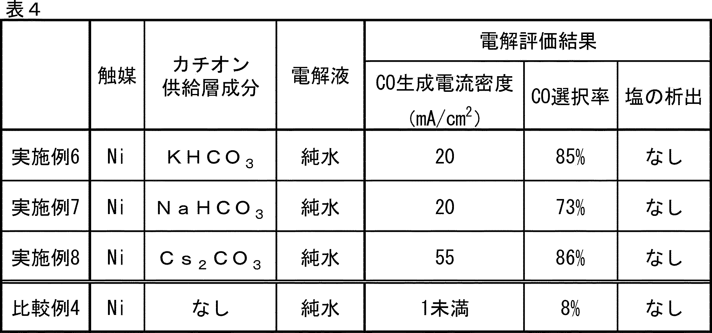
結果を表4~5に示す。
なお、触媒種がNiである系(実施例6~8及び比較例4)の結果を表4に;触媒種がAgである系(実施例9及び比較例5)の結果を表5に示した。

20 二酸化炭素還元電極用触媒層
21 反応層
22 アルカリ金属イオン及び高分子材を含む層(カチオン供給層)
23 触媒
24 アルカリ金属イオン及び高分子材
30 固体電解質(イオン交換膜)
40 アノード(陽極)
50 イオン交換膜-電極接合体
100 カソード集電板
200 カソード(陰極)
300 固体電解質(イオン交換膜)
400 アノード(陽極)
500 アノード集電板
600 電解液
700 電圧印加部
800 固体電解質形電解装置
Claims (13)
- 触媒と、アルカリ金属イオンと、前記アルカリ金属イオンを放出可能な高分子材とを含有する二酸化炭素還元電極用触媒層。
- 前記触媒及び前記アルカリ金属イオンが、前記アルカリ金属イオンを放出可能な高分子材中に分散され、一体となっている請求項1に記載の二酸化炭素還元電極用触媒層。
- 前記二酸化炭素還元電極用触媒層は、前記触媒を含む反応層と、前記アルカリ金属イオン及び前記アルカリ金属イオンを放出可能な高分子材を含む層とを有する請求項1に記載の二酸化炭素還元電極用触媒層。
- 前記触媒を含む反応層と、前記アルカリ金属イオン及び前記アルカリ金属イオンを放出可能な高分子材を含む層とが一体に設けられる請求項3に記載の二酸化炭素還元電極用触媒層。
- 前記アルカリ金属イオンを放出可能な高分子材は、陽イオン交換樹脂を含む請求項1又は2に記載の二酸化炭素還元電極用触媒層。
- 前記アルカリ金属イオンを放出可能な高分子材は、高分子ゲルを含む請求項1、3又は4のいずれか1項に記載の二酸化炭素還元電極用触媒層。
- 前記触媒が、銅イオン、ニッケルイオン、鉄イオン、コバルトイオン、亜鉛イオン、マンガンイオン、モリブデンイオン、及びアルミニウムイオンからなる群より選ばれる金属イオンと、窒素含有化合物と、炭素含有担体とを有する触媒A;及び、金、銀、銅、ニッケル、鉄、コバルト、亜鉛、クロム、パラジウム、スズ、マンガン、アルミニウム、インジウム、ビスマス、モリブデン、及び窒化炭素からなる群より選ばれる無機微粒子;または、銅、ニッケル、鉄、コバルト、亜鉛、マンガン、モリブデン、及びアルミニウムからなる群より選ばれる金属若しくは該金属のイオンに配位子が配位した金属錯体と、炭素含有担体とを有する触媒Bからなる群より選択される1つ以上を含む請求項1~6のいずれか1項に記載の二酸化炭素還元電極用触媒層。
- 請求項1~7のいずれか1項に記載の二酸化炭素還元電極用触媒層と、ガス拡散層とを有するカソード。
- 請求項8に記載のカソードと、固体電解質と、アノードとを有するイオン交換膜-電極接合体。
- 前記固体電解質が、陰イオン交換膜である請求項9に記載のイオン交換膜-電極接合体。
- 請求項8に記載のカソードと、
前記カソードと一対の電極を構成するアノードと、
前記カソードと前記アノードとの間に接触状態にて介在する固体電解質と、
前記カソードと前記アノードとの間に電圧を印加する電圧印加部と
を有する固体電解質形電解装置。 - 更に、前記アノードに接する電解液を有し、前記電解液が純水である請求項11に記載の固体電解質形電解装置。
- 前記固体電解質が、陰イオン交換膜である請求項11又は12に記載の固体電解質形電解装置。
Priority Applications (5)
| Application Number | Priority Date | Filing Date | Title |
|---|---|---|---|
| KR1020257015362A KR20250107183A (ko) | 2022-11-10 | 2023-10-05 | 이산화 탄소 환원 전극용 촉매층, 캐소드, 이온 교환막-전극 접합체 및 고체 전해질형 전해 장치 |
| JP2024557068A JPWO2024101045A1 (ja) | 2022-11-10 | 2023-10-05 | |
| AU2023376214A AU2023376214A1 (en) | 2022-11-10 | 2023-10-05 | Carbon dioxide reduction electrode catalyst layer, cathode, ion exchange membrane-electrode assembly and solid electrolyte electrolysis device |
| DE112023004691.3T DE112023004691T5 (de) | 2022-11-10 | 2023-10-05 | Kohlendioxid-reduktions-elektroden-katalysatorschicht, kathode, ionenaustausch-membran-elektroden-anordnung und fest-elektrolyt-elektrolyse-vorrichtung |
| CN202380078297.0A CN120187897A (zh) | 2022-11-10 | 2023-10-05 | 二氧化碳还原电极用催化剂层、阴极、离子交换膜-电极接合体和固体电解质型电解装置 |
Applications Claiming Priority (2)
| Application Number | Priority Date | Filing Date | Title |
|---|---|---|---|
| JP2022-180274 | 2022-11-10 | ||
| JP2022180274 | 2022-11-10 |
Publications (1)
| Publication Number | Publication Date |
|---|---|
| WO2024101045A1 true WO2024101045A1 (ja) | 2024-05-16 |
Family
ID=91032688
Family Applications (1)
| Application Number | Title | Priority Date | Filing Date |
|---|---|---|---|
| PCT/JP2023/036307 Ceased WO2024101045A1 (ja) | 2022-11-10 | 2023-10-05 | 二酸化炭素還元電極用触媒層、カソード、イオン交換膜-電極接合体及び固体電解質形電解装置 |
Country Status (7)
| Country | Link |
|---|---|
| JP (1) | JPWO2024101045A1 (ja) |
| KR (1) | KR20250107183A (ja) |
| CN (1) | CN120187897A (ja) |
| AU (1) | AU2023376214A1 (ja) |
| DE (1) | DE112023004691T5 (ja) |
| TW (1) | TW202419686A (ja) |
| WO (1) | WO2024101045A1 (ja) |
Cited By (1)
| Publication number | Priority date | Publication date | Assignee | Title |
|---|---|---|---|---|
| EP4711498A1 (en) * | 2024-09-13 | 2026-03-18 | Kabushiki Kaisha Toshiba | Membrane electrode assembly and electrochemical cell |
Citations (3)
| Publication number | Priority date | Publication date | Assignee | Title |
|---|---|---|---|---|
| CN111359651A (zh) * | 2020-04-26 | 2020-07-03 | 浙江大学 | 过渡金属-氮配位的碳凝胶电催化剂及其制备方法和应用 |
| JP2022510842A (ja) * | 2018-11-28 | 2022-01-28 | オプス-12 インコーポレイテッド | 電解槽および使用方法 |
| WO2022184905A2 (en) * | 2021-03-04 | 2022-09-09 | Totalenergies Onetech | Co2 electroreduction to multi-carbon products in strong acid |
-
2023
- 2023-10-05 KR KR1020257015362A patent/KR20250107183A/ko active Pending
- 2023-10-05 DE DE112023004691.3T patent/DE112023004691T5/de active Pending
- 2023-10-05 WO PCT/JP2023/036307 patent/WO2024101045A1/ja not_active Ceased
- 2023-10-05 JP JP2024557068A patent/JPWO2024101045A1/ja active Pending
- 2023-10-05 AU AU2023376214A patent/AU2023376214A1/en active Pending
- 2023-10-05 CN CN202380078297.0A patent/CN120187897A/zh active Pending
- 2023-10-06 TW TW112138475A patent/TW202419686A/zh unknown
Patent Citations (3)
| Publication number | Priority date | Publication date | Assignee | Title |
|---|---|---|---|---|
| JP2022510842A (ja) * | 2018-11-28 | 2022-01-28 | オプス-12 インコーポレイテッド | 電解槽および使用方法 |
| CN111359651A (zh) * | 2020-04-26 | 2020-07-03 | 浙江大学 | 过渡金属-氮配位的碳凝胶电催化剂及其制备方法和应用 |
| WO2022184905A2 (en) * | 2021-03-04 | 2022-09-09 | Totalenergies Onetech | Co2 electroreduction to multi-carbon products in strong acid |
Cited By (1)
| Publication number | Priority date | Publication date | Assignee | Title |
|---|---|---|---|---|
| EP4711498A1 (en) * | 2024-09-13 | 2026-03-18 | Kabushiki Kaisha Toshiba | Membrane electrode assembly and electrochemical cell |
Also Published As
| Publication number | Publication date |
|---|---|
| CN120187897A (zh) | 2025-06-20 |
| TW202419686A (zh) | 2024-05-16 |
| DE112023004691T5 (de) | 2025-08-21 |
| AU2023376214A1 (en) | 2025-06-05 |
| KR20250107183A (ko) | 2025-07-11 |
| JPWO2024101045A1 (ja) | 2024-05-16 |
Similar Documents
| Publication | Publication Date | Title |
|---|---|---|
| JP7819836B2 (ja) | 電解槽および使用方法 | |
| Abdelkader-Fernandez et al. | Oxygen evolution reaction electrocatalytic improvement in POM@ ZIF nanocomposites: a bidirectional synergistic effect | |
| Sarkar et al. | An overview on Pd-based electrocatalysts for the hydrogen evolution reaction | |
| Luo et al. | Trimetallic molybdate nanobelts as active and stable electrocatalysts for the oxygen evolution reaction | |
| Bhowmik et al. | CoFe layered double hydroxide supported on graphitic carbon nitrides: an efficient and durable bifunctional electrocatalyst for oxygen evolution and hydrogen evolution reactions | |
| Wei et al. | One-step synthesis of a self-supported copper phosphide nanobush for overall water splitting | |
| Xin et al. | Understanding Pt nanoparticle anchoring on graphene supports through surface functionalization | |
| Xia et al. | Multistep sulfur leaching for the development of a highly efficient and stable NiS x/Ni (OH) 2/NiOOH electrocatalyst for anion exchange membrane water electrolysis | |
| Samanta et al. | IrO2-Modified RuO2 nanowires/nitrogen-doped carbon composite for effective overall water splitting in all pH | |
| Wang et al. | A Comparative Study of Composition and Morphology Effect of Ni x Co1–x (OH) 2 on Oxygen Evolution/Reduction Reaction | |
| CN113493917A (zh) | 二氧化碳电解池用电极催化剂层、及具备其的电解池和二氧化碳电解用电解装置 | |
| CA3041625A1 (en) | Electrocatalyst composition comprising noble metal oxide supported on tin oxide | |
| Hu et al. | Synthesis of anti-poisoning spinel Mn–Co–C as cathode catalysts for low-temperature anion exchange membrane direct ammonia fuel cells | |
| CN115697553A (zh) | 具有不含铂族金属的自支撑析氧电极的阴离子交换膜电解槽 | |
| Yan et al. | Recent progress in electrocatalytic conversion of CO2 to valuable C2 products | |
| Salah et al. | Interface engineering induced by low Ru doping in Ni/Co@ NC derived from Ni-ZIF-67 for enhanced electrocatalytic overall water splitting | |
| JPWO2019240200A1 (ja) | 触媒及びその使用方法 | |
| Xie et al. | Elucidating the mechanism of oxygen evolution reaction on nanostructured copper-based catalysts | |
| Xiao et al. | Co–Fe–Se ultrathin nanosheet-fabricated microspheres for efficient electrocatalysis of hydrogen evolution | |
| US20250146145A1 (en) | Catalyst and production method for same, cathode, ion exchange membrane electrode assembly, and solid electrolyte electrolysis device | |
| Zhu et al. | Polyoxometalate-derived electrocatalysts enabling progress in hydrogen evolution reactions | |
| KR20250107183A (ko) | 이산화 탄소 환원 전극용 촉매층, 캐소드, 이온 교환막-전극 접합체 및 고체 전해질형 전해 장치 | |
| WO2024166617A1 (ja) | 触媒の製造方法、カソード、イオン交換膜-電極接合体及び固体電解質形電解装置 | |
| US20250154673A1 (en) | Additive for carbon dioxide reduction catalysts, catalyst layer, cathode, ion exchange membrane-electrode assembly and solid electrolyte electrolysis device | |
| WO2023163042A1 (ja) | 触媒、カソード、イオン交換膜-電極接合体及び固体電解質形電解装置 |
Legal Events
| Date | Code | Title | Description |
|---|---|---|---|
| 121 | Ep: the epo has been informed by wipo that ep was designated in this application |
Ref document number: 23888398 Country of ref document: EP Kind code of ref document: A1 |
|
| WWE | Wipo information: entry into national phase |
Ref document number: 2024557068 Country of ref document: JP |
|
| WWE | Wipo information: entry into national phase |
Ref document number: 202380078297.0 Country of ref document: CN |
|
| WWE | Wipo information: entry into national phase |
Ref document number: AU2023376214 Country of ref document: AU |
|
| WWE | Wipo information: entry into national phase |
Ref document number: 202547053952 Country of ref document: IN |
|
| ENP | Entry into the national phase |
Ref document number: 2023376214 Country of ref document: AU Date of ref document: 20231005 Kind code of ref document: A |
|
| WWE | Wipo information: entry into national phase |
Ref document number: 112023004691 Country of ref document: DE |
|
| WWP | Wipo information: published in national office |
Ref document number: 202547053952 Country of ref document: IN |
|
| WWP | Wipo information: published in national office |
Ref document number: 202380078297.0 Country of ref document: CN |
|
| WWP | Wipo information: published in national office |
Ref document number: 1020257015362 Country of ref document: KR |
|
| WWP | Wipo information: published in national office |
Ref document number: 112023004691 Country of ref document: DE |
|
| 122 | Ep: pct application non-entry in european phase |
Ref document number: 23888398 Country of ref document: EP Kind code of ref document: A1 |