WO2024096018A1 - 全固体二次電池及びその製造方法 - Google Patents
全固体二次電池及びその製造方法 Download PDFInfo
- Publication number
- WO2024096018A1 WO2024096018A1 PCT/JP2023/039312 JP2023039312W WO2024096018A1 WO 2024096018 A1 WO2024096018 A1 WO 2024096018A1 JP 2023039312 W JP2023039312 W JP 2023039312W WO 2024096018 A1 WO2024096018 A1 WO 2024096018A1
- Authority
- WO
- WIPO (PCT)
- Prior art keywords
- positive electrode
- negative electrode
- active material
- solid
- material layer
- Prior art date
- Legal status (The legal status is an assumption and is not a legal conclusion. Google has not performed a legal analysis and makes no representation as to the accuracy of the status listed.)
- Ceased
Links
Images






Classifications
-
- H—ELECTRICITY
- H01—ELECTRIC ELEMENTS
- H01M—PROCESSES OR MEANS, e.g. BATTERIES, FOR THE DIRECT CONVERSION OF CHEMICAL ENERGY INTO ELECTRICAL ENERGY
- H01M50/00—Constructional details or processes of manufacture of the non-active parts of electrochemical cells other than fuel cells, e.g. hybrid cells
- H01M50/10—Primary casings; Jackets or wrappings
- H01M50/116—Primary casings; Jackets or wrappings characterised by the material
- H01M50/122—Composite material consisting of a mixture of organic and inorganic materials
-
- H—ELECTRICITY
- H01—ELECTRIC ELEMENTS
- H01M—PROCESSES OR MEANS, e.g. BATTERIES, FOR THE DIRECT CONVERSION OF CHEMICAL ENERGY INTO ELECTRICAL ENERGY
- H01M10/00—Secondary cells; Manufacture thereof
- H01M10/04—Construction or manufacture in general
- H01M10/0404—Machines for assembling batteries
-
- H—ELECTRICITY
- H01—ELECTRIC ELEMENTS
- H01M—PROCESSES OR MEANS, e.g. BATTERIES, FOR THE DIRECT CONVERSION OF CHEMICAL ENERGY INTO ELECTRICAL ENERGY
- H01M10/00—Secondary cells; Manufacture thereof
- H01M10/05—Accumulators with non-aqueous electrolyte
- H01M10/052—Li-accumulators
-
- H—ELECTRICITY
- H01—ELECTRIC ELEMENTS
- H01M—PROCESSES OR MEANS, e.g. BATTERIES, FOR THE DIRECT CONVERSION OF CHEMICAL ENERGY INTO ELECTRICAL ENERGY
- H01M10/00—Secondary cells; Manufacture thereof
- H01M10/05—Accumulators with non-aqueous electrolyte
- H01M10/056—Accumulators with non-aqueous electrolyte characterised by the materials used as electrolytes, e.g. mixed inorganic/organic electrolytes
- H01M10/0561—Accumulators with non-aqueous electrolyte characterised by the materials used as electrolytes, e.g. mixed inorganic/organic electrolytes the electrolyte being constituted of inorganic materials only
- H01M10/0562—Solid materials
-
- H—ELECTRICITY
- H01—ELECTRIC ELEMENTS
- H01M—PROCESSES OR MEANS, e.g. BATTERIES, FOR THE DIRECT CONVERSION OF CHEMICAL ENERGY INTO ELECTRICAL ENERGY
- H01M10/00—Secondary cells; Manufacture thereof
- H01M10/05—Accumulators with non-aqueous electrolyte
- H01M10/058—Construction or manufacture
- H01M10/0585—Construction or manufacture of accumulators having only flat construction elements, i.e. flat positive electrodes, flat negative electrodes and flat separators
-
- H—ELECTRICITY
- H01—ELECTRIC ELEMENTS
- H01M—PROCESSES OR MEANS, e.g. BATTERIES, FOR THE DIRECT CONVERSION OF CHEMICAL ENERGY INTO ELECTRICAL ENERGY
- H01M10/00—Secondary cells; Manufacture thereof
- H01M10/42—Methods or arrangements for servicing or maintenance of secondary cells or secondary half-cells
- H01M10/4235—Safety or regulating additives or arrangements in electrodes, separators or electrolyte
-
- H—ELECTRICITY
- H01—ELECTRIC ELEMENTS
- H01M—PROCESSES OR MEANS, e.g. BATTERIES, FOR THE DIRECT CONVERSION OF CHEMICAL ENERGY INTO ELECTRICAL ENERGY
- H01M4/00—Electrodes
- H01M4/02—Electrodes composed of, or comprising, active material
- H01M4/13—Electrodes for accumulators with non-aqueous electrolyte, e.g. for lithium-accumulators; Processes of manufacture thereof
-
- H—ELECTRICITY
- H01—ELECTRIC ELEMENTS
- H01M—PROCESSES OR MEANS, e.g. BATTERIES, FOR THE DIRECT CONVERSION OF CHEMICAL ENERGY INTO ELECTRICAL ENERGY
- H01M50/00—Constructional details or processes of manufacture of the non-active parts of electrochemical cells other than fuel cells, e.g. hybrid cells
- H01M50/10—Primary casings; Jackets or wrappings
- H01M50/102—Primary casings; Jackets or wrappings characterised by their shape or physical structure
- H01M50/103—Primary casings; Jackets or wrappings characterised by their shape or physical structure prismatic or rectangular
-
- H—ELECTRICITY
- H01—ELECTRIC ELEMENTS
- H01M—PROCESSES OR MEANS, e.g. BATTERIES, FOR THE DIRECT CONVERSION OF CHEMICAL ENERGY INTO ELECTRICAL ENERGY
- H01M50/00—Constructional details or processes of manufacture of the non-active parts of electrochemical cells other than fuel cells, e.g. hybrid cells
- H01M50/10—Primary casings; Jackets or wrappings
- H01M50/116—Primary casings; Jackets or wrappings characterised by the material
- H01M50/117—Inorganic material
-
- H—ELECTRICITY
- H01—ELECTRIC ELEMENTS
- H01M—PROCESSES OR MEANS, e.g. BATTERIES, FOR THE DIRECT CONVERSION OF CHEMICAL ENERGY INTO ELECTRICAL ENERGY
- H01M50/00—Constructional details or processes of manufacture of the non-active parts of electrochemical cells other than fuel cells, e.g. hybrid cells
- H01M50/10—Primary casings; Jackets or wrappings
- H01M50/116—Primary casings; Jackets or wrappings characterised by the material
- H01M50/121—Organic material
-
- H—ELECTRICITY
- H01—ELECTRIC ELEMENTS
- H01M—PROCESSES OR MEANS, e.g. BATTERIES, FOR THE DIRECT CONVERSION OF CHEMICAL ENERGY INTO ELECTRICAL ENERGY
- H01M50/00—Constructional details or processes of manufacture of the non-active parts of electrochemical cells other than fuel cells, e.g. hybrid cells
- H01M50/10—Primary casings; Jackets or wrappings
- H01M50/116—Primary casings; Jackets or wrappings characterised by the material
- H01M50/124—Primary casings; Jackets or wrappings characterised by the material having a layered structure
- H01M50/1245—Primary casings; Jackets or wrappings characterised by the material having a layered structure characterised by the external coating on the casing
-
- H—ELECTRICITY
- H01—ELECTRIC ELEMENTS
- H01M—PROCESSES OR MEANS, e.g. BATTERIES, FOR THE DIRECT CONVERSION OF CHEMICAL ENERGY INTO ELECTRICAL ENERGY
- H01M50/00—Constructional details or processes of manufacture of the non-active parts of electrochemical cells other than fuel cells, e.g. hybrid cells
- H01M50/10—Primary casings; Jackets or wrappings
- H01M50/131—Primary casings; Jackets or wrappings characterised by physical properties, e.g. gas permeability, size or heat resistance
-
- H—ELECTRICITY
- H01—ELECTRIC ELEMENTS
- H01M—PROCESSES OR MEANS, e.g. BATTERIES, FOR THE DIRECT CONVERSION OF CHEMICAL ENERGY INTO ELECTRICAL ENERGY
- H01M50/00—Constructional details or processes of manufacture of the non-active parts of electrochemical cells other than fuel cells, e.g. hybrid cells
- H01M50/50—Current conducting connections for cells or batteries
- H01M50/572—Means for preventing undesired use or discharge
- H01M50/584—Means for preventing undesired use or discharge for preventing incorrect connections inside or outside the batteries
- H01M50/586—Means for preventing undesired use or discharge for preventing incorrect connections inside or outside the batteries inside the batteries, e.g. incorrect connections of electrodes
-
- H—ELECTRICITY
- H01—ELECTRIC ELEMENTS
- H01M—PROCESSES OR MEANS, e.g. BATTERIES, FOR THE DIRECT CONVERSION OF CHEMICAL ENERGY INTO ELECTRICAL ENERGY
- H01M50/00—Constructional details or processes of manufacture of the non-active parts of electrochemical cells other than fuel cells, e.g. hybrid cells
- H01M50/50—Current conducting connections for cells or batteries
- H01M50/572—Means for preventing undesired use or discharge
- H01M50/584—Means for preventing undesired use or discharge for preventing incorrect connections inside or outside the batteries
- H01M50/59—Means for preventing undesired use or discharge for preventing incorrect connections inside or outside the batteries characterised by the protection means
- H01M50/591—Covers
-
- Y—GENERAL TAGGING OF NEW TECHNOLOGICAL DEVELOPMENTS; GENERAL TAGGING OF CROSS-SECTIONAL TECHNOLOGIES SPANNING OVER SEVERAL SECTIONS OF THE IPC; TECHNICAL SUBJECTS COVERED BY FORMER USPC CROSS-REFERENCE ART COLLECTIONS [XRACs] AND DIGESTS
- Y02—TECHNOLOGIES OR APPLICATIONS FOR MITIGATION OR ADAPTATION AGAINST CLIMATE CHANGE
- Y02E—REDUCTION OF GREENHOUSE GAS [GHG] EMISSIONS, RELATED TO ENERGY GENERATION, TRANSMISSION OR DISTRIBUTION
- Y02E60/00—Enabling technologies; Technologies with a potential or indirect contribution to GHG emissions mitigation
- Y02E60/10—Energy storage using batteries
-
- Y—GENERAL TAGGING OF NEW TECHNOLOGICAL DEVELOPMENTS; GENERAL TAGGING OF CROSS-SECTIONAL TECHNOLOGIES SPANNING OVER SEVERAL SECTIONS OF THE IPC; TECHNICAL SUBJECTS COVERED BY FORMER USPC CROSS-REFERENCE ART COLLECTIONS [XRACs] AND DIGESTS
- Y02—TECHNOLOGIES OR APPLICATIONS FOR MITIGATION OR ADAPTATION AGAINST CLIMATE CHANGE
- Y02P—CLIMATE CHANGE MITIGATION TECHNOLOGIES IN THE PRODUCTION OR PROCESSING OF GOODS
- Y02P70/00—Climate change mitigation technologies in the production process for final industrial or consumer products
- Y02P70/50—Manufacturing or production processes characterised by the final manufactured product
Definitions
- the present invention relates to an all-solid-state secondary battery and a method for manufacturing the same.
- the all-solid-state secondary battery has a battery unit in which a negative electrode active material layer, a solid electrolyte layer, and a positive electrode active material layer are laminated in this order as battery element members.
- a stacked type all-solid-state secondary battery in which two or more battery units are stacked has been developed for practical use in order to achieve high energy density.
- all-solid-state secondary batteries are usually constructed by sequentially stacking a positive electrode active material layer and a negative electrode active material layer with a solid electrolyte layer interposed therebetween, there is a problem that the ends of a battery unit in which constituent layers such as a negative electrode active material layer, a solid electrolyte layer, and a positive electrode active material layer are stacked are likely to come into contact with each other. That is, even if the layers are stacked with a solid electrolyte layer interposed therebetween, the ends of the positive electrode active material layer and the negative electrode active material layer are likely to come into contact with each other, causing a short circuit.
- Patent Document 1 describes an electrochemical element including "an electrode body for an electrochemical element having a positive electrode, a negative electrode, and a solid electrolyte layer interposed between the positive electrode and the negative electrode, the solid electrolyte layer containing a sulfide-based solid electrolyte, and an insulating layer containing a filler and a binder, the filler containing a resin having a melting point or thermal decomposition temperature of 150° C.
- Patent Document 2 describes an all-solid-state lithium battery comprising: an oriented positive electrode plate made of an oriented polycrystal formed by orienting a plurality of lithium transition metal oxide particles; a solid electrolyte layer provided on the oriented positive electrode plate and made of a lithium ion conductive material; a negative electrode layer provided on the solid electrolyte layer; and an end insulating part insulating an end of the oriented positive electrode plate, the solid electrolyte layer side surface of the end insulating part forming a single surface continuous with the solid electrolyte layer side surface of the oriented positive electrode plate, such that there is no step between the end insulating part and the solid electrolyte layer side surface of the oriented positive electrode plate, or the solid electrolyte layer side surface of the end insulating part is a discontinuous surface lower than the solid electrolyte layer side surface of the oriented positive electrode plate, but the step between the end insulating part and the solid electrolyte
- the constituent layers constituting the battery unit are formed by various methods, such as a film-forming method (a method of applying and drying a constituent layer-forming material containing solid particles such as an inorganic solid electrolyte, an active material, and a conductive assistant), and a method of sputtering or vapor-depositing an active material.
- a film-forming method a method of applying and drying a constituent layer-forming material containing solid particles such as an inorganic solid electrolyte, an active material, and a conductive assistant
- a method of sputtering or vapor-depositing an active material Regardless of the manufacturing method, the ends of the formed constituent layers tend to be thin and are prone to poor adhesion, which induces the occurrence of short circuits at the ends of the battery element members (battery unit, constituent layers).
- an all-solid-state secondary battery battery unit
- the ends of the constituent layers are deformed by the pressure stress, and defects (cracks, breaks, chips, etc.) occur due to the breakdown of the solid particle adhesion, which ultimately causes a short circuit.
- the all-solid-state secondary battery in addition to the short circuit caused by the stacking of the constituent layers (contact of the constituent layers) described above, the all-solid-state secondary battery also has the problem that short circuits are likely to occur at the ends of the battery element members due to the end formability of the constituent layers and pressurization.
- the all-solid-state secondary battery of Patent Document 1 prevents the occurrence of short circuits that can occur when constituent layers are simply stacked by providing an insulating layer on the side of the electrode body, while the all-solid-state secondary battery of Patent Document 2 prevents short circuits caused by steps that occur when an oriented positive plate is used by providing an end covering part that insulates the end of the oriented positive plate.
- Patent Documents 1 nor 2 is there any consideration given to the formability of the ends of the constituent layers or the occurrence of deformation or defects at the ends.
- the all-solid-state secondary battery of Patent Document 2 which uses an oriented positive plate, does not have the problem of deformation or defects at the ends of the constituent layers.
- the objective of the present invention is to provide an all-solid-state secondary battery that can prevent deformation and defects while maintaining the insulation of the ends of the battery element members, thereby suppressing the occurrence of short circuits, and a method for manufacturing the same.
- insulating covering that covers the ends (at least the side surfaces) of a battery element member, including a battery unit formed of stacked constituent layers, from the outside of the side surfaces, and by forming this insulating covering from a mixture of a resin material that melts in a temperature range of 300°C or less and insulating inorganic particles that do not melt at 350°C, it is possible to prevent the occurrence of deformation and defects while maintaining the insulation of the ends of the battery element member.
- the present invention was completed after further investigation based on these findings.
- An all-solid-state secondary battery having a battery element member,
- the battery element member includes at least one battery unit in which a negative electrode active material layer, a solid electrolyte layer, and a positive electrode active material layer are laminated in this order, an insulating cover is provided at an end of the battery element member, the insulating cover covering at least a side surface of the battery element member from outside the side surface;
- the insulating coating is a mixture of a resin material that melts in a temperature range of 300°C or lower and insulating inorganic particles that do not melt at 350°C, in an all-solid-state secondary battery.
- the battery unit is a battery unit in which a negative electrode current collector, a negative electrode active material layer, a solid electrolyte layer, a positive electrode active material layer, and a positive electrode current collector are laminated in this order,
- the all-solid-state secondary battery according to ⁇ 1> wherein the positive electrode current collector has a positive electrode current collecting portion laminated adjacent to the positive electrode active material layer, and a positive electrode tab extending so as to protrude from one end of the positive electrode current collecting portion, and the positive electrode tab protrudes from the insulating covering.
- the battery unit is a battery unit in which a negative electrode current collector, a negative electrode active material layer, a solid electrolyte layer, a positive electrode active material layer, and a positive electrode current collector are laminated in this order,
- ⁇ 4> The all-solid-state secondary battery according to any one of ⁇ 1> to ⁇ 3>, wherein the insulating coating is made of a molten solid of a resin material that melts in a temperature range of 200° C. or lower and insulating solid particles that do not melt at 250° C.
- ⁇ 5> The all-solid-state secondary battery according to any one of ⁇ 1> to ⁇ 4>, wherein a recess adjacent to the outer side in the planar direction of the positive electrode active material layer or the negative electrode active material layer formed at an end of a battery element due to a dimensional difference between the positive electrode active material layer and the negative electrode active material layer is filled with an insulating coating containing insulating inorganic particles.
- ⁇ 6> The all-solid-state secondary battery according to any one of ⁇ 1> to ⁇ 5>, wherein at least one interface between adjacent stacked layers in the battery element member has a coating intrusion region in which an insulating coating containing at least one insulating inorganic particle intrudes from an end portion of the battery element member toward the inside.
- ⁇ 7> The all-solid-state secondary battery according to ⁇ 6>, in which the solid electrolyte layer in contact with the coating intrusion region has no cracks.
- a battery element member including at least one laminate unit in which a negative electrode active material layer, a solid electrolyte layer, and a positive electrode active material layer are laminated in this order; and applying pressure in an inward direction to the battery element members while heating the mixture at a temperature at which the resin material melts.
- the manufacturing method according to ⁇ 8> further comprising carrying out a step of pressing the battery element members while pressing them in the stacking direction.
- the all-solid-state secondary battery of the present invention can prevent contact between the constituent layers at the ends of the battery element members to maintain the insulation of the ends, while reinforcing the ends to prevent deformation and defects, thereby suppressing the occurrence of short circuits. Also, the manufacturing method of the all-solid-state secondary battery of the present invention can manufacture an all-solid-state secondary battery in which the occurrence of short circuits is suppressed.
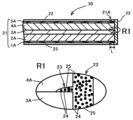
- FIG. 1 is a vertical cross-sectional view showing a schematic basic configuration of a typical all-solid-state secondary battery.
- FIG. 2 is a partial schematic cross-sectional view showing an end portion of a preferred embodiment of the all-solid-state secondary battery of the present invention.
- FIG. 3 is a partial schematic cross-sectional view showing an end portion of another preferred embodiment of the all-solid-state secondary battery of the present invention.
- FIG. 4 is a partial schematic cross-sectional view showing another end portion of another preferred embodiment of the all-solid-state secondary battery of the present invention.
- FIG. 5 is a partial schematic cross-sectional view showing another end portion of another preferred embodiment of the all-solid-state secondary battery of the present invention.
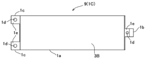
- FIG. 6A is a top schematic view showing one embodiment of a positive electrode plate that can be used in a preferred method of making a battery element member.
- FIG. 6B is a schematic top view showing one embodiment of a negative electrode plate with an electrolyte layer that can be used in a preferred method for producing a battery element member.
- FIG. 7 is a schematic top view showing a state in which a plurality of electrode plates are accommodated in the accommodation space of a frame and provisionally positioned in a preferred method for producing a battery element member using a preferred production apparatus.
- FIG. 8(A) is a schematic cross-sectional view illustrating the initial state of this positioning step in a preferred method for manufacturing a battery element member using a preferred manufacturing apparatus, and shows a cross section taken along a plane perpendicular to the longitudinal direction of the frame body and passing through the center of the pin receiving portion.
- Figure 8 (B) is a schematic cross-sectional view illustrating the completed state of this positioning step in a preferred method for manufacturing a battery element component using a preferred manufacturing apparatus, and shows a cross section taken along a plane perpendicular to the longitudinal direction of the frame body and passing through the center of the pin receiving portion.
- FIG. 9 is a schematic cross-sectional view showing a state in which the positioned battery element members are pressurized and restrained in the stacking direction in a preferred manufacturing method for a stacked-type all-solid-state secondary battery using a preferred manufacturing apparatus, and shows a cut surface along a plane perpendicular to the longitudinal direction of the frame and passing through the center of the pin receiving portion.
- FIG. 10 is a schematic cross-sectional view showing a state in which the positioned battery element members are pressurized and restrained in the stacking direction in a preferred manufacturing method for a stacked-type all-solid-state secondary battery using a preferred manufacturing apparatus, and shows a cut surface perpendicular to the longitudinal direction of the frame and approximately at the center in the longitudinal direction.
- FIG. 10 is a schematic cross-sectional view showing a state in which the positioned battery element members are pressurized and restrained in the stacking direction in a preferred manufacturing method for a stacked-type all-solid-state secondary battery using a preferred manufacturing apparatus, and shows
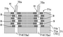
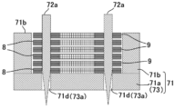
- FIG. 11 is a schematic cross-sectional view illustrating a method for forming an insulating cover on an end portion of a battery element by placing a rod-shaped body in the vicinity of the end portion of the battery element and applying pressure thereto, in a preferred method for producing a stacked-type all-solid-state secondary battery using a preferred production apparatus.
- the term "principal surface” refers to a surface perpendicular to the thickness direction of a flat plate such as a constituent layer, and usually refers to a surface having the largest surface area.
- the term “plane direction” refers to the in-plane direction of the principal surface, specifically, the vertical and horizontal directions.
- insulating refers to having electronic insulating properties, that is, the property of not allowing electrons to pass through.
- the electrical conductivity is 10 -9 S (Siemens)/cm or less at a measurement temperature of 25°C.
- the "crack”, “crack” and “chip” that may occur in the constituent layer are all defects caused by the breakdown of the bond between solid particles.
- the "crack” refers to a crack that extends continuously along the grain boundary of at least one solid particle in the depth direction or surface direction of the constituent layer. For example, when observed with an electron microscope, it is recognized as a crack that has progressed along the grain boundary of at least one solid particle. Usually, once a crack occurs, stress is concentrated at the tip of the crack, so the crack progresses linearly and does not follow the grain boundary of the solid particle.
- the "crack” refers to a state in which the crack penetrates in the depth direction and surface direction and the constituent layer loses its integrity (separates into multiple pieces), and the “chip” refers to a state in which a part of the constituent layer is partially peeled off or missing (missing) (excluding a cracked state).
- any of the upper and lower limits can be appropriately combined to form a specific numerical range.
- the upper and lower limits forming the numerical range are not limited to the specific combinations written before and after " ⁇ " as specific numerical ranges, but can be a numerical range that appropriately combines the upper and lower limits of each numerical range.
- a numerical range expressed using " ⁇ ” means a range that includes the numerical values written before and after " ⁇ " as the upper and lower limits.
- the ends of the battery element members are covered with an insulating cover, and this insulating cover can maintain the insulation of the ends of the battery element members (battery unit, constituent layers) and reinforce the strength of the ends of the constituent layers to prevent deformation and defects, thereby suppressing the occurrence of short circuits.
- the insulating properties of the ends can be maintained and the strength of the composite layers can be reinforced by integrally covering the ends of the battery element members.
- the all-solid-state secondary battery of the present invention has high reliability whether it is a single-layer type or a laminate type.
- the end of a battery element member refers to a region including at least the side surface (end face) of the battery element member, and in the case where there is a dimensional difference between the positive electrode active material layer and the negative electrode active material layer, refers to a region including a recess formed by this dimensional difference (in other words, a region formed by a straight line connecting the outer side surfaces of the battery element member and a straight line connecting the inner surface of the recess).
- the insulating cover does not directly contact the end (side) of the negative electrode active material layer, but this form is also included in the present invention as one form of the end of the battery element member. In this form, a compressive pressure toward the inside of the battery element member is transmitted to the end (side) of the negative electrode active material layer via the solid electrolyte layer.
- the all-solid-state secondary battery of the present invention is the same as a known all-solid-state secondary battery except that the ends of the battery element members are covered with an insulating cover, and other configurations are not particularly limited.
- the all-solid-state secondary battery of the present invention includes both forms of an all-solid-state secondary battery having one battery unit (laminated unit) in which at least a negative electrode active material layer, a solid electrolyte layer, and a positive electrode active material layer are laminated in this order (sometimes referred to as a single-layer type all-solid-state secondary battery), and a form of an all-solid-state secondary battery having two or more battery units (sometimes referred to as a laminated type all-solid-state secondary battery).
- the number of battery units in the laminated type all-solid-state secondary battery is not particularly limited as long as it is two or more, and can be, for example, 2 to 500 sets, and preferably 60 to 100 sets.
- the shape of the all-solid-state secondary battery of the present invention is not particularly limited and can be appropriately set depending on the application, etc. For example, it can be circular or rectangular in plan view.
- "rectangle" means a quadrangular shape including a square and a rectangle, but is not limited to a geometrically accurate quadrangular shape, and may be approximately quadrangular depending on the application, required characteristics, etc., and may also be a shape with chamfered corners.
- the outer dimensions of the all-solid-state secondary battery can be appropriately set depending on the application, etc.
- FIG. 1 shows the basic configuration (battery unit) of a typical all-solid-state secondary battery.
- the all-solid-state secondary battery 10 has a configuration in which, viewed from the negative electrode side, a negative electrode current collector 1, a negative electrode active material layer 2, a solid electrolyte layer 3, a positive electrode active material layer 4, and a positive electrode current collector 5 are laminated in this order. Adjacent layers are in direct contact with each other.
- electrons (e - ) are supplied to the negative electrode side, and at the same time, the alkali metal or alkaline earth metal constituting the positive electrode active material is ionized.
- the ionized ions move through (conduct) the solid electrolyte layer 3 and are accumulated in the negative electrode.
- lithium ions Li +
- the alkali metal ions or alkaline earth metal ions stored in the negative electrode are returned to the positive electrode side, supplying electrons to the operating part 6.
- a light bulb is used as the operating part 6, and this is turned on by discharge.
- the single-layer type all-solid-state secondary battery of the present invention includes, as battery element members, a set of battery units in which a negative electrode active material layer, a solid electrolyte layer, and a positive electrode active material layer are laminated in this order, and preferably includes the basic configuration shown in FIG. 1 in which a negative electrode current collector and a positive electrode current collector are further laminated.
- FIG. 2 shows a schematic diagram of a cross section along the stacking direction of a preferred embodiment of the all-solid-state secondary battery (single-layer type) of the present invention, illustrating the entire end portion and the vicinity of the interface between the solid electrolyte layer and the positive electrode active material layer (the region indicated by R1 in FIG. 2 ).
- This all-solid-state secondary battery 30 is a single-layer type all-solid-state secondary battery 30 having a battery element member 21 consisting of a set of battery units having the layer structure shown in Fig. 1 as a basic unit. That is, the all-solid-state secondary battery 30 has a battery element member 21 consisting of a set of battery units 21 in which, as viewed from the negative electrode side, a negative electrode current collector 1A, a negative electrode active material layer 2A, a solid electrolyte layer 3A, a positive electrode active material layer 4A, and a positive electrode current collector 5A are laminated in this order.
- the negative electrode current collector 1A, the negative electrode active material layer 2A, the solid electrolyte layer 3A, the positive electrode active material layer 4A, and the positive electrode current collector 5A all have the same surface area of the main surface.
- the battery element member 21 has an insulating cover 22 at the end 21A that covers at least the side surface from the outside of the side surface. As shown in FIG. 2, the insulating cover 22 integrally and entirely covers the peripheral side surface of the battery element member 21, sealing it without any gaps.
- the insulating cover 22 preferably covers the side surface of the end 21A from the outside toward the inside in a compressed state.
- the insulating cover 22 is disposed on the outside in contact with the side surface of the battery element member 21, and covers the main surfaces near the edges of the negative electrode current collector 1A and the positive electrode current collector 5A in addition to the side surface of the battery element member 21.
- the amount of coverage by the insulating cover 22 on the main surface near the edge is not particularly limited and can be, for example, 0.1 mm or more, and is preferably 0.5 to 2 mm.
- the end 21A of the battery element member 21 has the insulating cover 22, it is possible to prevent the occurrence of deformation and defects (disintegration, destruction) while maintaining the insulation of the end 21A of the battery element member 21 (battery unit, constituent layer).
- the all-solid-state secondary battery 30 can suppress the occurrence of short circuits and exhibits high reliability.
- the interface between the adjacently stacked solid electrolyte layer 3A and the positive electrode active material layer 4A has a coating penetration region 23 formed by an insulating coating 22 containing at least one insulating inorganic particle 24 penetrating the interface from the end 21A (side surface) of the battery element member 21 toward the inside (inside of the main surface).
- This coating penetration region 23 has at least one insulating inorganic particle 24 in a resin material 25 described later in the penetration region to the interface.
- the strength can be reinforced and made strong, and deformation of the end 21A of the battery element member 21 and the occurrence of defects in the constituent layers, particularly the solid electrolyte layer 3A, can be highly suppressed.
- defects are likely to occur at the ends of the solid electrolyte layer 3A, but the solid electrolyte layer 3A in contact with the coating penetration area 23 is prevented from developing defects such as cracks, breaks, and chips, and can be maintained in a defect-free state.
- the number of insulating inorganic particles 24 contained in the coating body intrusion region 23 is not particularly limited as long as it is one or more, and is set appropriately and not uniquely depending on the size of the insulating inorganic particles 24, the intrusion amount of the coating body intrusion region 23, etc.
- the number of insulating inorganic particles 24 present in the coating body intrusion region 23 is preferably such that a plurality of insulating inorganic particles 24 are filled, and can be, for example, 10 or more.
- the upper limit is not particularly limited, but 50 or less is practical.
- the coating penetration region 23 only needs to be present at the interface, and its penetration amount (penetration length from the side surface of the positive electrode active material layer 4A toward the inside: depth), average thickness in the stacking direction, etc.
- the penetration amount depends on the size of the positive electrode active material layer 4A, but can be, for example, 0.05 mm or more, and is preferably 0.1 to 0.5 mm.
- the average thickness of the coating penetration region 23 depends on the layer thicknesses of the solid electrolyte layer 3A and the positive electrode active material layer 4A, but can be, for example, 200 ⁇ m or less, and is preferably 20 to 60 ⁇ m.
- the presence, amount of penetration and thickness of the coating intrusion region 23, as well as the presence and number of insulating inorganic particles, can be confirmed or measured, for example, by observation with a scanning electron microscope (SEM).
- the positive electrode collector 5A has a positive electrode tab for electrical connection
- the negative electrode collector 1A has a negative electrode tab for electrical connection.
- each end is the same as the end 21A except that the positive electrode tab or the negative electrode tab penetrates the insulating cover and protrudes outward from the outer surface of the insulating cover.
- the positive electrode tab or the negative electrode tab is partially covered or buried in the insulating cover on the positive electrode current collector side or the negative electrode current collector side.
- the method of forming the end is basically the same as the end 21, and the method of forming the end on which the positive electrode tab or the negative electrode tab is arranged in the laminated all-solid-state secondary battery described later can also be applied.
- the end of the single-layered all-solid-state secondary battery 30 can be formed, for example, by a method of arranging a mixture so as to sandwich the positive electrode tab or the negative electrode tab from above and below in the stacking direction and pressing it toward the inside of the battery element member.
- the laminated all-solid-state secondary battery of the present invention includes two or more battery units each having a negative electrode active material layer, a solid electrolyte layer, and a positive electrode active material layer laminated in this order as battery element members, and preferably includes the basic configuration shown in Fig. 1 in which a negative electrode current collector and a positive electrode current collector are further laminated. In this configuration, adjacent battery units share the negative electrode current collector or the positive electrode current collector.
- the all-solid-state secondary battery 50 is formed by alternately stacking a plurality of positive electrode active material layers 4B and a plurality of negative electrode active material layers 2B via a solid electrolyte layer 3B, and has a battery element member 41 consisting of five battery units 42 with the layer structure shown in FIG. 1 as a basic unit. That is, as shown in FIG.
- the all-solid-state secondary battery 50 has a battery element member 41 in which five battery units 42 each having a negative electrode current collector 1B, a negative electrode active material layer 2B, a solid electrolyte layer 3B, a positive electrode active material layer 4B, and a positive electrode current collector 5B stacked in this order from the negative electrode side are stacked in such a way that the stacking order of the constituent layers is alternately reversed.
- two adjacent battery units 42 share one current collector. That is, the negative electrode active material layers 2B are provided on both main surfaces of one negative electrode current collector 1B, and the positive electrode active material layers 4B are provided on both main surfaces of one positive electrode current collector 5B. As shown in FIG.
- the stacking order of the constituent layers in this stacked-type all-solid-state secondary battery 50 is positive electrode current collector 5B-positive electrode active material layer 4B-solid electrolyte layer 3B-negative electrode active material layer 2B-negative electrode current collector 1B-negative electrode active material layer 2B-solid electrolyte layer 3B-positive electrode active material layer 4B, .... 3, but as is clear from Fig. 4 and Fig. 5, the current collector of the all-solid-state secondary battery 50 has a current collecting portion laminated adjacent to the active material layer and a tab connected to one end of the current collecting portion so as to protrude from the current collecting portion, as described below.
- the positive electrode current collectors are laminated so that the positive electrode tabs are located on the same end side, and the negative electrode current collectors are laminated so that the negative electrode tabs are located on an end side different from the end where the positive electrode tabs are located, usually on the opposite end side.
- the main surface area of the positive electrode active material layer 4B is set smaller than that of the negative electrode active material layer 2B.
- the main surface area of the positive electrode active material layer is set smaller than that of the negative electrode active material layer to prevent short circuit due to stacking misalignment.
- the positive electrode current collector 5B and the positive electrode active material layer 4B have the same end surface due to punching of the coating sheet, etc.
- the negative electrode current collector 1B and the negative electrode active material layer 2B have the same end surface due to punching of the coating sheet, etc.
- the solid electrolyte layer 3B is transferred onto the negative electrode active material, so it has the same end surface as the negative electrode current collector 1B and the negative electrode active material layer 2B.
- a recess 43 adjacent to the surface direction outer side of the positive electrode active material layer 4B is formed at the end 41A (the end where the positive electrode tab and the negative electrode tab are not arranged) of the battery element member 41. More specifically, as shown in FIG. 3, at the end 41A of the battery element member 41, a recess 43 is formed by the side surface of the positive electrode plate (two positive electrode active material layers 4B and the positive electrode current collector 5B) and the two solid electrolyte layers 3B sandwiching the positive electrode plate, adjacent to the surface direction outer side of the positive electrode active material layer 4B.
- a short circuit is very likely to occur at the end of the battery element member, and deformation and defects are also likely to occur.
- the stacked all-solid-state secondary battery 50 has an insulating coating 44, the occurrence of short circuits and deformations at the end 41A of the battery element member 41 can be highly suppressed.
- the positive electrode active material layer 4B smaller than the negative electrode active material layer 2B, and not only the occurrence of short circuits due to insufficient reliability of the end 41A, but also the occurrence of short circuits due to stacking misalignment can be highly suppressed.
- the battery element member 41 has an insulating cover 44 at the end 41A, which covers at least the side surface from the outside of the side surface. As shown in FIG. 3, the insulating cover 44 integrally and entirely covers the peripheral side surface of the battery element member 41 (five battery units 42), sealing it without gaps.
- the insulating cover 44 preferably covers the side surface of each end in a compressed state from the outside toward the inside.
- the insulating cover 44 is disposed in an area that contacts the side surface of each constituent layer from the outside of the side surface of the constituent layer located at the outermost side in the surface direction.
- the insulating cover 44 is also filled with insulating inorganic particles 46 in the recess 43 formed by the dimensional difference between the positive electrode active material layer 4B and the negative electrode active material layer 2B without gaps.
- the insulating cover 44 also covers the main surfaces near the edges of the negative electrode collector 1B that is the outermost (lowest layer in FIG. 3) in the stacking direction and the positive electrode collector 5B that is the outermost (top layer in FIG. 3).
- the amount of coverage by the insulating cover 44 on the main surface near the edge is not particularly limited and can be, for example, 0.1 mm or more, and is preferably 0.5 to 2 mm.
- the length in the plane direction L of the insulating cover in a stacked-type all-solid-state secondary battery refers to the average length from the side surface in the plane direction of the constituent layer located outermost in the plane direction, that is, the negative electrode active material layer 2B and the solid electrolyte layer 3B in the battery element member 41, to the outer surface in the plane direction, as shown in FIG.
- the end 41A of the battery element member 41 has the insulating cover 44, even in a stacked type all-solid-state secondary battery 50 in which the positive electrode active material layer 4B is set small, the occurrence of deformation and defects (collapse, destruction) can be prevented while maintaining the insulation of the end 41A of the battery element member 41 (battery unit 42, constituent layer).
- this all-solid-state secondary battery 50 can suppress the occurrence of short circuits and exhibits high reliability.
- At least one interface between the adjacently stacked solid electrolyte layer 3B and the positive electrode active material layer 4B has a coating penetration region 45 formed by an insulating coating 44 containing at least one insulating inorganic particle 46 penetrating the interface from the end 41A of the battery element member 41 toward the inside (inside of the main surface).
- the interface having this coating penetration region 45 exists within the recess 43.
- the coating penetration region 45 has at least one insulating inorganic particle 46 in a resin material 47 described later in the penetration region into the interface.
- the strength can be reinforced and made strong, and deformation of the end 41A of the battery element member 41 and the occurrence of defects in the constituent layers, particularly the solid electrolyte layer 3B, can be highly suppressed.
- defects are likely to occur at the ends of the solid electrolyte layer 3B, but the solid electrolyte layer 3B in contact with the coating penetration area 45 is able to maintain a defect-free state by suppressing the occurrence of defects such as cracks, breaks, and chips.
- the coating intrusion region 45 is present at all interfaces between the adjacently stacked solid electrolyte layers 3B and the positive electrode active material layers 4B, but as will be described later, it does not have to be present at all interfaces.
- the number of insulating inorganic particles 46 contained in the coating body intrusion region 45 is not particularly limited as long as it is one or more, and is set appropriately and not uniquely depending on the size of the insulating inorganic particles 46, the intrusion amount of the coating body intrusion region 45, etc.
- the number of insulating inorganic particles 46 present in the coating body intrusion region 45 is preferably such that a plurality of insulating inorganic particles 46 are filled, and can be, for example, 10 or more.
- the upper limit is not particularly limited, but 50 or less is practical.
- the penetration amount (penetration length from the side surface of the positive electrode active material layer 4B toward the inside: depth), average thickness in the stacking direction, etc. of the coating penetration region 45 can be appropriately determined.
- the penetration amount depends on the size of the positive electrode active material layer 4B, but can be, for example, 0.01 mm or more, and is preferably 0.02 to 0.1 mm.
- the average thickness of the coating penetration region 45 depends on the layer thicknesses of the solid electrolyte layer 3B and the positive electrode active material layer 4B, but can be, for example, 200 ⁇ m or less, and is preferably 20 to 60 ⁇ m.
- the presence, amount and thickness of the coating intrusion region 45, as well as the presence and number of insulating inorganic particles, can be confirmed or measured as described above.
- This stacked all-solid-state secondary battery 50 has a positive electrode tab to which each positive electrode current collector 5B is electrically connected, and the positive electrode tabs are electrically connected to each other outside the stacked all-solid-state secondary battery 50. Also, the stacked all-solid-state secondary battery 50 has a negative electrode tab to which each negative electrode current collector 1B is electrically connected, and the negative electrode tabs are electrically connected to each other outside the stacked all-solid-state secondary battery 50. Therefore, although not shown in FIG.
- the stacked all-solid-state secondary battery 50 has a rectangular shape in a plan view having four ends, namely, two ends 41A where the positive electrode tab and the negative electrode tab are not arranged, an end 41B where the positive electrode tab is arranged, and an end 41C where the negative electrode tab is arranged.
- each end 41B or 41C is the same as the end 41A except that a plurality of positive electrode tabs or a plurality of negative electrode tabs penetrate the insulating cover 44B or 44C and protrude outward from the outer surface of the insulating cover, as shown in Fig. 4 or 5.
- FIG. 4 is a partial schematic cross-sectional view showing, in a cross section along the stacking direction in a preferred embodiment (stack-type all-solid-state secondary battery 50) of the all-solid-state secondary battery (stack-type) of the present invention, an end 41B at which the positive electrode tab 5b is arranged, and FIG.
- FIG. 5 is a partial schematic cross-sectional view showing, in a cross section along the stacking direction in a preferred embodiment (stack-type all-solid-state secondary battery 50) of the all-solid-state secondary battery (stack-type) of the present invention, an end 41C at which the negative electrode tab 1b is arranged.
- the laminated all-solid-state secondary battery 50 includes a battery element member 41 including at least one battery unit 42 in which at least a negative electrode collector 1B, a negative electrode active material layer 2B, a solid electrolyte layer 3B, a positive electrode active material layer 4B, and a positive electrode collector 5B are laminated in this order.
- the positive electrode collector 5B has a positive electrode collector part 5a laminated adjacent to the positive electrode active material layer 4B, and a positive electrode tab (positive electrode terminal) 5b provided so as to protrude from one end of the positive electrode collector 5a, as described later.
- the positive electrode collector 5B is laminated so that the positive electrode tab 5b is located on the same end side, and the negative electrode collector 1B is laminated so that the negative electrode tab 1b is located on an end side different from the end where the positive electrode tab 5b is located, usually on the opposite end side.
- the laminated all-solid-state secondary battery 50 has an insulating cover 44B that covers at least the side surface of the battery element member 41 from the outside of the side surface at the end 41B where the positive electrode tab 5b is arranged, and the positive electrode tab 5b penetrates the insulating cover 44B and protrudes outward from the outer surface of the insulating cover 44B.
- This insulating cover 44B is formed of a mixture described later.
- this all-solid-state secondary battery 50 can suppress the occurrence of short circuits and exhibits high reliability.
- a recess 43B adjacent to the outer side of the positive electrode active material layer 4B in the surface direction is formed at the end 41B of the battery element member 41 where the positive electrode tab 5b is arranged. More specifically, a recess 43B is formed at the end 41B of the battery element member 41 adjacent to the outer side of the surface direction of the positive electrode active material layer 4B by the positive electrode tab 5b, the side surface of the positive electrode active material layer 4B, and the solid electrolyte layer 3B. In other words, the end 41B has a recess 43B in which the recess 43 of the end 41A is divided into two by the positive electrode tab 5b.
- This end 41B also has an insulating cover 44B in the recess 43B like the end 41A, so that the occurrence of a short circuit due to contact between the positive electrode tab 5b and each end of the negative electrode current collector 1B or the negative electrode active material layer 2B can be highly suppressed.
- the positive electrode tabs 5b protrude and lead out to the outside of the laminated all-solid-state secondary battery 50, that is, to the outside of the insulating cover 41B.
- the positive electrode tabs 5b may be in contact with each other inside the insulating cover 41B as long as they are not in contact with the negative electrode current collector 1B and the negative electrode active material layer 2B in the all-solid-state secondary battery 50, but it is preferable that they are not in contact with each other.
- the protruding portion of the positive electrode tab 5b is not covered with the insulating cover 41B, and is arranged, for example, along the surface of the insulating cover 44B, and is electrically connected to each other by welding or the like to form an integrated unit.
- the amount of coverage of the positive electrode tab 5b by the insulating cover 44B (the length in the planar direction of the positive electrode tab 5b embedded in the insulating cover 44B from the connection part with the positive electrode current collector 5a) is not particularly limited, and can be, for example, 0.1 mm or more, and is preferably 0.5 to 2 mm.
- the laminated all-solid-state secondary battery 50 includes the battery element member 42 shown in Fig. 4.
- the negative electrode current collector 1B has a negative electrode current collector 1a laminated adjacent to the negative electrode active material layer 2B, as described later, and a negative electrode tab (negative electrode terminal) 1b provided so as to protrude from one end of the negative electrode current collector 1a.
- the negative electrode current collector 1B is laminated such that the negative electrode tab 1b is located on the same end side as described above.
- the laminated all-solid-state secondary battery 50 has an insulating cover 44C that covers at least the side surface of the battery element member 41 from the outside of the side surface at the end 41C where the negative electrode tab 1b is arranged, and the negative electrode tab 1b penetrates the insulating cover 44C and protrudes outward from the outer surface of the insulating cover 44C.
- This insulating cover 44C is formed of a mixture described later. In this way, when the end 41C has the insulating cover 44C, even if the end 41C has the negative electrode tab 1b, it is possible to prevent the occurrence of deformation and defects (collapse, destruction) while maintaining the insulation of the end 41C. As a result, this all-solid-state secondary battery 50 can suppress the occurrence of short circuits and exhibits high reliability.
- a recess 43C is formed adjacent to the outer side of the positive electrode active material layer 4B in the surface direction at the end 41C of the battery element member 41 where the negative electrode tab 1b is disposed. More specifically, a recess 43C is formed adjacent to the outer side of the positive electrode active material layer 4B in the surface direction at the end 41C of the battery element member 41 by the side surface of the positive electrode plate (two positive electrode active material layers 4B and positive electrode current collector 5B) and the two solid electrolyte layers 3B sandwiching the positive electrode plate. This recess 43C is the same as the recess 43 of the end 41A.
- This end 41C also has an insulating cover 44C in the recess 43C like the end 41A, so that short circuits due to contact between the negative electrode tab and each end of the positive electrode current collector or the positive electrode active material layer can be highly suppressed.
- the negative electrode tabs 1b protrude and lead out to the outside of the laminated all-solid-state secondary battery 50, that is, to the outside of the insulating cover 41C, similarly to the positive electrode tabs 5b.
- the negative electrode tabs 1b may be in contact with each other inside the insulating cover 41C as long as they are not in contact with the positive electrode collector 5B and the positive electrode active material layer 4B in the all-solid-state secondary battery 50, but it is preferable that they are not in contact with each other.
- the protruding portion of the negative electrode tab 1b is not covered with the insulating cover 41C, and is disposed, for example, along the surface of the insulating cover 44C, and is electrically connected to each other by welding or the like to be integrated.
- the amount of coverage of the negative electrode tab 1b by the insulating cover 44C (the length in the surface direction of the negative electrode tab 1b embedded in the insulating cover 44C from the connection part with the negative electrode current collector 1a) is not particularly limited, and can be, for example, 0.1 mm or more, and is preferably 0.5 to 2 mm.
- the single-layer type all-solid-state secondary battery and the stacked type all-solid-state secondary battery of the present invention are not limited to the above-mentioned configurations, and can be appropriately modified within a range that does not impair the effects of the present invention.
- the insulating cover does not need to integrally surround (enclose) the peripheral side of the end of the battery element member, but only needs to cover at least one end of the battery element member, for example, an end of the battery element member that is likely to cause a short circuit, deformation, or defect.
- the insulating cover does not need to cover the main surfaces near the edges of the negative electrode collector and the positive electrode collector, but only needs to cover at least the side of the battery element member.
- the insulating cover covers the main surface near the edge (part of the positive electrode tab 5b is buried) as shown in FIG.
- the insulating cover covers the main surface near the edge as shown in FIG. 5.
- the coating penetration region is preferably present at at least one interface between adjacently stacked constituent layers in the battery element member, more preferably at at least one interface at at least one end, and even more preferably at at least one interface at each end.
- the interface at which the coating penetration region exists is not limited to the interface between the adjacently stacked solid electrolyte layer and the positive electrode active material layer, but may be any interface between adjacently stacked constituent layers, for example, the interface between the solid electrolyte layer and the negative electrode active material layer.
- the coating penetration region is usually more likely to exist preferentially at an interface where the interfacial adhesion of adjacently stacked constituent layers is weak, and can be formed, for example, at the interface between adjacently stacked constituent layers without applying pressure, or at the interface between adjacently stacked constituent layers that are pressurized and pressed together with a weak pressure during the manufacture of the all-solid-state secondary battery.
- the coating penetration region may exist at multiple interfaces, but does not need to exist at all interfaces. For example, in a single-layered all-solid-state secondary battery and a stacked all-solid-state secondary battery, the ratio of the number of interfaces having a coating penetration region to all interfaces between adjacently stacked constituent layers at one end can be 5% or more, and may be 10 to 90%.
- the ratio of the number of interfaces having a coating penetration region to all interfaces between adjacently stacked identical constituent layers at one end can be 10% or more, and may be 50 to 100%.
- the interface where the coating penetration region exists is not limited to the interface of the constituent layer that forms a recess, but may be an interface between constituent layers that have a large main surface area and do not form a recess.
- the single-layer all-solid-state secondary battery does not need to have a positive electrode active material layer, a solid electrolyte layer, and a negative electrode active material layer with the same main surface area, and the positive electrode active material layer and the negative electrode active material layer may have a dimensional difference in the main surface area.
- an insulating covering is filled in a recess formed by the solid electrolyte layer and the current collector due to the dimensional difference.
- the main surface area of the positive electrode active material layer is usually set to be smaller than that of the negative electrode active material layer, but in the present invention, the main surface area of the negative electrode active material layer can also be set to be smaller than that of the positive electrode active material layer, and the positive electrode active material layer and the negative electrode active material layer do not need to have a dimensional difference in their main surface areas and may have the same main surface area.
- the main surface area of the negative electrode active material layer is set to be smaller than that of the positive electrode active material layer, the end of the laminated all-solid-state secondary battery will have a recess adjacent to the outer side in the surface direction of the negative electrode active material layer.
- the stacked type all-solid-state secondary battery is not limited to a configuration in which the battery units are stacked such that the stacking order of the constituent layers is alternately reversed as shown in FIG. 3, but may be a configuration in which the battery units are stacked such that the stacking order of the constituent layers is the same.
- the insulating cover is made of a mixture containing a resin material and insulating inorganic particles.
- the resin material is a resin material having physical properties that allow it to melt in a temperature range of 300° C. or lower.
- melts at a temperature range of 300° C. or lower means that it melts at a temperature range of 300° C. or lower under 1 atmospheric pressure, and is in a molten state at a temperature of at least 300° C.
- the mixture can be heated to a temperature at which the resin material melts while maintaining the particle shape of the insulating inorganic particles, and the mixture melts by this heating and deforms in response to pressure so as to cover the end of the battery element member while maintaining the mixed state with the insulating inorganic particles. At the same time, it can penetrate into the gaps of the battery element member and also flow into the recesses to fill the recesses, sealing or filling the end including the gaps and recesses. Then, by cooling and solidifying the resin material, an insulating covering made of the resolidified mixture is formed, and a state in which the battery element member is covered with virtually no gaps along the shape of the end can be created.
- the molten resin material can penetrate into the constituent layers to reinforce the constituent layers (bonded state of solid particles). Furthermore, while maintaining the mixed state with the insulating inorganic particles, it can penetrate into the interface between the constituent layers to form a covering body intrusion area containing the insulating inorganic particles. In this way, the end of the battery element member is covered and reinforced with the insulating covering body.
- the resin material has electronic insulation properties and can maintain the insulation properties of the ends of the battery element members.
- the resin material has a physical property of being thermally melted in a temperature range of 300°C or less, preferably in a temperature range of 200°C or less, and more preferably in a temperature range of 150°C or less.
- the melting of the resin material can be confirmed by the softening point at which the complex viscosity decreases by one order of magnitude or more within a temperature change range of 40°C in the following shear test using a viscoelasticity measuring device. Therefore, the resin material having a physical property of being thermally melted in a temperature range of XXX°C or less means that the softening point (maximum temperature change range of 40°C) is included in a temperature range of XXX°C or less.
- XXX°C means 300°C, 200°C, or 150°C.
- ⁇ Test conditions> The measurement conditions for vibration measurement using a viscoelasticity measuring device MCR302 (trade name, manufactured by Anton Paar) and parallel plates are as follows. Angular frequency: 6.28 rad/s Measurement mode: Temperature dependence mode Temperature: 25 to 200°C Heating rate: 25 to 190°C over 400 seconds, then 200°C over 200 seconds
- the resin material preferably has a complex viscosity of 10 Pa ⁇ s or more and 100,000 Pa ⁇ s or less at 190° C.
- the complex viscosity at 190° C. is the value measured under the above ⁇ Measurement Conditions>.
- the resin material has a physical property that, when cooled after melting, it becomes solid and covers the end portion. For example, it is preferable that the resin material becomes solid at 60°C.
- thermoplastic resins various resins that satisfy the above-mentioned melting characteristics can be used.
- thermoplastic resins thermoplastic elastomers, and thermosetting resins can be mentioned, with thermoplastic resins and thermoplastic elastomers being preferred.
- thermoplastic resin and thermoplastic elastomer known resins and the like can be used, and examples thereof include thermoplastic elastomers such as polyolefin-based thermoplastic elastomers containing polyethylene, polypropylene, or the like as hard segments, polystyrene-based thermoplastic elastomers, polyvinyl chloride-based thermoplastic elastomers, polyurethane-based thermoplastic elastomers, polyester-based thermoplastic elastomers, polyamide-based thermoplastic elastomers, polybutadiene-based thermoplastic elastomers, and ethylene-vinyl acetate-based thermoplastic elastomers (EVA).
- thermoplastic elastomers such as polyolefin-based thermoplastic elastomers containing polyethylene, polypropylene, or the like as hard segments, polystyrene-based thermoplastic elastomers, polyvinyl chloride-based thermoplastic elastomers, polyurethane-based thermoplastic
- polyolefin-based thermoplastic elastomers containing polyethylene, polypropylene, or the like as hard segments are preferred in terms of the small side reactions with lithium-ion battery materials, while EVA is preferred in terms of the ease with which a coating body penetration region that encases insulating inorganic particles is formed.
- the vinyl acetate content in the EVA is preferably 11 to 28 mass %
- the softening point is preferably in the range of 70 to 115°C
- a hot melt adhesive composition having a complex viscosity at 190°C of 10 to 100 cps is preferably used.
- the mixture may contain one or more types of resin materials.
- the weight average molecular weight of the entire resin materials contained in the mixture is preferably 8,000 to 100,000 at the stage when the insulating coating is formed.
- the resin material may be in the form of a resin (polymer) when forming the insulating coating, and when included in the mixture, it may be either a resin or a polymerizable compound (monomer) that forms a resin. It may also contain additives such as a polymerization initiator.
- the insulating inorganic particles have electronic insulating properties and maintain the edge insulation of the battery element members.
- the insulating inorganic particles have a physical property such that they do not melt at 350° C. Furthermore, the insulating inorganic particles are not easily deformed even when pressure is applied during the manufacture and use of the all-solid-state secondary battery, and maintain their particle state, functioning as aggregates that resist pressure in the insulating coating.
- the mixture can be heated to a temperature at which the resin material melts while maintaining the particle shape of the insulating inorganic particles, creating a state in which the end of the battery element component is covered virtually without any gaps along the shape of the end, and the insulating inorganic particles function as aggregates in the insulating coating to prevent deformation and defects in the end of the battery element component.
- the insulating inorganic particles preferably have a physical property of not melting at a temperature at which the resin material melts, for example, preferably have a physical property of not melting at 250° C.
- the fact that the insulating inorganic particles do not melt can be easily confirmed by not having the above-mentioned softening point in a shear measurement test using a viscoelasticity measuring device.
- a vertical load of 50 N is applied to parallel plates.
- the measurement conditions for vibration measurement using a viscoelasticity measuring device MCR302 (trade name, manufactured by Anton Paar) and parallel plates are as follows. A load of 50 N is applied to the parallel plate.
- Measurement mode Temperature dependence mode Temperature: 25 to 250°C Heating rate: 25 to 190°C over 400 seconds, then 250°C over 200 seconds
- various inorganic particles can be used, for example, particles of metal oxide, metal nitride, metal carbide, metal carbonate, etc., and metal oxide particles are preferred in that they have high hardness and can be produced inexpensively by sintering in air.
- the metal oxide is not particularly limited, but examples thereof include aluminum oxide, zirconium oxide, silicon oxide, zeolite, cerium oxide, calcium oxide, magnesium oxide, and the like. Among these, aluminum oxide and silicon oxide are preferred because they are hard and can be inexpensively produced into particles with a uniform particle size.
- the metal nitrides, metal carbides, and metal carbonates are not particularly limited, but examples thereof include nitrides, carbides, and carbonates of aluminum, zirconium, silicon, cerium, calcium, magnesium, and the like.
- the mixture may contain one type or two or more types of insulating inorganic particles.
- the shape of the insulating inorganic particles is not particularly limited, and may be spherical, granular, flat, amorphous, or the like.
- the particle size of the insulating inorganic particles is not particularly limited, but is usually set smaller than the layer thickness of the constituent layer, and is preferably set smaller than the average layer thickness of the positive electrode active material layer.
- the particle size of the insulating inorganic particles is the D 90 diameter (diameter below which 90% of the population is) measured by a particle size distribution measuring device (MT3300 (trade name), Microtrack Co., Ltd.) using a laser diffraction/scattering method.
- the lower limit of the particle size of the insulating inorganic particles is not particularly limited, but is usually set larger than the solid particles forming the constituent layer.
- the particle size (D 90 diameter) of the insulating inorganic particles can be specifically set to 0.01 to 100 ⁇ m, and is preferably 0.5 to 60 ⁇ m.
- the content of the resin material in the mixture is preferably 6 to 50% by mass, more preferably 8 to 40% by mass, and even more preferably 10 to 30% by mass.
- the content of the insulating inorganic particles in the mixture is preferably 50 to 94 mass %, more preferably 60 to 92 mass %, and even more preferably 70 to 90 mass %.
- the ratio of the content of the insulating inorganic particles to the content of the resin material is not particularly limited, but is preferably, for example, 1 to 15.6, more preferably 1.5 to 11.5, and even more preferably 2.3 to 9.
- the above contents and content ratios are also the same for the insulating coating.
- the mixture is a mixture of a resin material and insulating inorganic particles, and includes a form in which it is a mixture of a resin and insulating inorganic particles, and a form in which it is a mixture of a polymerizable compound and insulating inorganic particles, with a mixture of a resin and insulating inorganic particles being preferred.
- This mixture is preferably a molten solid obtained by melt-mixing a mixture of a resin material and insulating inorganic particles in advance and then solidifying, and is more preferably a molten solid of a resin material and insulating inorganic particles.
- the molten solid may be a molten solid of a mixture of a resin material that melts in a temperature range of 300°C or less and insulating inorganic particles that do not melt at 350°C, but is preferably a molten solid of a mixture of a resin material that melts in a temperature range of 200°C or less and insulating solid particles that do not melt at 250°C.
- the mixture preferably does not contain an insulating inorganic material that has electronic insulation properties, is solid at 100°C (i.e., has a melting point above 100°C), and has physical properties that cause it to melt in a temperature range of 200°C or less.
- insulating inorganic materials include sulfur (elemental sulfur) and/or modified sulfur, iodine, and a mixture of iodine and sulfur.
- the fact that the mixture does not contain an insulating inorganic material means that the content of the insulating inorganic material in the mixture is less than 5% by mass, and preferably 1% by mass or less.
- the solid electrolyte layer is an electronically insulating electrolyte layer, and any solid electrolyte layer that is used as a solid electrolyte layer in an all-solid-state secondary battery can be used without any particular limitation.
- the solid electrolyte layer includes an inorganic solid electrolyte.
- the inorganic solid electrolyte is not particularly limited, and can be any of the usual components, such as a sulfide-based inorganic solid electrolyte and an oxide-based inorganic solid electrolyte.
- the reliability of the end of the battery element can be improved, a soft and brittle sulfide-based inorganic solid electrolyte can be used, and an all-solid-state secondary battery exhibiting high ionic conductivity can be realized.
- the shape of the inorganic solid electrolyte is not particularly limited, and can be spherical, granular, flat, amorphous, or the like.
- the particle size of the inorganic solid electrolyte is not particularly limited, but is preferably smaller than the particle size of the insulating inorganic particles described above in terms of reinforcing the constituent layer with the insulating inorganic particles described above, and can be, for example, 0.5 to 20 ⁇ m.
- the particle size of the inorganic solid electrolyte is the D 90 diameter measured in the same manner as the particle size of the insulating inorganic particles described above.
- the content of the inorganic solid electrolyte in the solid electrolyte layer is not particularly limited, and can be, for example, 90 to 99 mass%.
- the solid electrolyte layer may contain a binder and other additives as appropriate. These binders and additives are not particularly limited, and may be any of the usual components used in all-solid-state secondary batteries.
- the dimensions (main surface area) of the solid electrolyte layer are not particularly limited and are set appropriately, and are usually set to the same dimensions as the negative electrode active material layer.
- the thickness of the solid electrolyte layer is not particularly limited and can be determined appropriately depending on the form (number of battery units), application, required characteristics, etc. of the all-solid-state secondary battery.
- the thickness of the solid electrolyte layer can be, for example, 5 to 300 ⁇ m, or can also be 30 to 50 ⁇ m.
- the solid electrolyte layer may be used alone, or may be used as an electrode plate laminated on an active material layer of a current collector.
- the negative electrode active material layer is at least an ion-conductive layer, and any layer that is used as a negative electrode active material layer for an all-solid-state secondary battery can be used without any particular limitation.
- the negative electrode active material layer may be a composite layer formed by binding solid particles containing the above-mentioned inorganic solid electrolyte and the negative electrode active material.
- the negative electrode active material is not particularly limited, and may be a carbonaceous material, a metal oxide, a metal composite oxide, or the like.
- the shape of the negative electrode active material is not particularly limited, and may be spherical, granular, flat, amorphous, or the like.
- the particle size of the negative electrode active material is not particularly limited, but is preferably smaller than the particle size of the above-mentioned insulating inorganic particles in terms of reinforcing the negative electrode active material layer with the above-mentioned insulating inorganic particles, and may be, for example, 0.5 to 55 ⁇ m.
- the particle size of the negative electrode active material is the D 90 diameter measured in the same manner as the particle size of the above-mentioned insulating inorganic particles.
- the content of the negative electrode active material in the negative electrode active material layer is not particularly limited, but may be, for example, 30 to 70 mass%.
- the content of the inorganic solid electrolyte in the negative electrode active material layer is not particularly limited, but may be, for example, 30 to 70 mass%.
- the negative electrode active material layer may contain a conductive assistant, a binder, and other additives that are commonly used.
- the dimensions (main surface area) of the negative electrode active material layer are not particularly limited and are set appropriately, and may be set to the same dimensions as the positive electrode active material layer, or may be set to a dimension larger than the positive electrode active material layer. In a laminated type all-solid-state secondary battery, the dimensions of the negative electrode active material layer are usually set to a dimension larger than the positive electrode active material layer.
- the dimensional difference between the negative electrode active material layer and the positive electrode active material layer is not particularly limited and can be set appropriately.
- the thickness of the negative electrode active material layer is not particularly limited and can be appropriately determined depending on the form (number of battery units), application, required characteristics, etc. of the all-solid-state secondary battery.
- the thickness of the negative electrode active material layer can be, for example, 5 to 300 ⁇ m, or can be 30 to 50 ⁇ m.
- the negative electrode active material layer may be used alone, or may be laminated on a negative electrode current collector to be described later and used as a negative electrode plate.
- the positive electrode active material layer is at least an ionically conductive layer, and any layer that is used as a positive electrode active material layer for an all-solid-state secondary battery can be used without any particular limitation.
- the positive electrode active material layer may be a composite layer formed by binding solid particles containing the inorganic solid electrolyte and the positive electrode active material described above.
- the positive electrode active material is not particularly limited, and transition metal oxides and the like may be used.
- the shape of the positive electrode active material is not particularly limited, and may be spherical, granular, flat, amorphous, and the like.
- the particle size of the positive electrode active material is not particularly limited, but is preferably smaller than the particle size of the insulating inorganic particles described above in terms of reinforcing the positive electrode active material layer with the insulating inorganic particles described above, and may be, for example, 0.5 to 55 ⁇ m.
- the particle size of the positive electrode active material is the D 90 diameter measured in the same manner as the particle size of the insulating inorganic particles described above.
- the content of the positive electrode active material in the positive electrode active material layer is not particularly limited, but may be, for example, 50 to 90 mass%.
- the content of the inorganic solid electrolyte in the positive electrode active material layer is not particularly limited, but may be, for example, 10 to 50 mass%.
- the positive electrode active material layer may contain a conductive assistant, a binder, and other additives that are commonly used.
- the dimensions (main surface area) of the positive electrode active material layer are not particularly limited and are set appropriately.
- the thickness of the positive electrode active material layer is not particularly limited and can be appropriately determined depending on the form (number of battery units) of the all-solid-state secondary battery, the application, the required characteristics, etc.
- the thickness of the positive electrode active material layer can be, for example, 5 to 300 ⁇ m, or can be 30 to 50 ⁇ m.
- the positive electrode active material layer may be used alone, or may be laminated on a positive electrode current collector described below to form a positive electrode plate.
- the negative electrode current collector and the positive electrode current collector can be made of any material that is used as a current collector for an all-solid-state secondary battery without any particular limitation.
- a metal plate such as aluminum, an aluminum alloy, copper, a copper alloy, stainless steel, nickel, iron, or titanium is used.
- the current collector may be a thin-plate current collector having a current collector laminated adjacent to the active material layer and a tab connected to one end of the current collector so as to protrude from the current collector, and it is preferable that the current collector has at least one positioning hole, since the battery unit or battery element can be produced in a shorter stacking time while maintaining high stacking accuracy.
- the tab is usually not in contact with the active material layer, and for example, an insulating part or the like is provided between the tab and the current collector or the end of the active material layer.
- the shape of the current collector is not particularly limited and is appropriately determined depending on the shape of the all-solid-state secondary battery, etc.
- the current collecting portion of the current collector is preferably in the form of a rectangular, usually rectangular, thin plate in a plan view.
- a preferred form of the current collector is a thin plate-like current collector having a current collector, a tab connected to one end of the current collector so as to protrude, and a substrate extension connected to the other end of the current collector (preferably the edge opposite to the one end of the current collector).
- Such a preferred current collector includes a positive electrode current collector 5C corresponding to the positive electrode plate 8 shown in FIG. 6A and a negative electrode current collector 1C corresponding to the negative electrode plate 9 shown in FIG. 6B.
- FIG. 6A shows a positive electrode plate 8 in which a positive electrode active material layer 4B is formed on a positive electrode current collector 5a.
- the positive electrode collector 5C has a rectangular positive electrode collector 5a in plan view, a pair of base extensions 5c extending from the vicinity of both ends (long side edge) of one of the short side edges to protrude in a substantially rectangular shape, and one positive electrode tab 5b extending from the vicinity of the other short side edge to protrude in a substantially rectangular shape.
- the negative electrode collector 1C has a rectangular negative electrode collector 1a in plan view, a pair of base extensions 1c extending from the vicinity of both ends (long side edge) of one of the short side edges to protrude in a substantially rectangular shape, and one negative electrode tab (also called a lead portion) 1b extending from the vicinity of the other short side edge to protrude in a substantially rectangular shape.
- the positive electrode current collector 5a and the negative electrode current collector 1a are regions laminated adjacent to the active material layers, where the positive electrode active material layer 4B and the negative electrode active material layer 2B are formed, respectively.
- the positive electrode tab 5b and the negative electrode tab 1b (hereinafter, sometimes collectively referred to as tabs) are members that become lead tabs in an all-solid-state secondary battery, and one circular positioning hole 5d or 1d is drilled inside, for example, at approximately the center.
- a pair of substrate extensions 5c and 1c are each drilled with one circular positioning hole 5d or 1d inside, for example, at approximately the center. The dimensions of the substrate extensions 5c and 1c and the tabs are determined appropriately.
- the end of the current collector without a tab or substrate extension (usually both ends on the long side) and the end of the current collector with a tab or substrate extension (usually both ends on the short side) are pressed against the mixture to flow inward and fill the recess of the battery element member, and it becomes necessary to remove the mixture attached to the tab or substrate extension before welding.
- the tab can be made longer so that the mixture does not adhere to the welded part, as in Example C described later.
- the region including the positioning hole on the current collecting part side of the tab, the entire surface of the base extension part, and more preferably the region for preventing the short circuit are each preferably covered with an insulating material such as an insulating resin, more preferably a mixture (melt solidified body) described later.
- an insulating material such as an insulating resin, more preferably a mixture (melt solidified body) described later.
- a tape-shaped molded body (melt solidified body) 5e or 1e obtained by molding the mixture into a tape shape is attached.
- an insulating cover can be formed by a manufacturing method described later.
- the shape of the positioning holes 1d and 5d is preferably similar to the cross-sectional shape perpendicular to the axis of the positioning pin described below, and may be, for example, circular, elliptical, polygonal, or star-shaped, with a circular shape being preferred.
- the inner diameter of the positioning holes is not particularly limited and is determined appropriately depending on the size of the battery element members, etc. As an example, it may be set to 1.0 to 6.0 mm.
- the current collectors may be the same or different, for example in terms of shape and positioning holes, and it is preferable that the positive electrode current collector and the negative electrode current collector are the same.
- the dimensions of the current collector are not particularly limited and can be appropriately determined depending on the application, required characteristics, etc.
- the part excluding the tab and the base extension part the area that prevents short circuit with the current collector
- the main surface area of the positive electrode current collector 5a is smaller than that of the negative electrode current collector 1a.
- the thickness of the current collector is also not particularly limited and can be appropriately determined depending on the form (number of battery units), application, required characteristics, and further strength of the all-solid-state secondary battery.
- the thickness of the current collector can be, for example, 5 to 30 ⁇ m.
- a functional layer may be provided between adjacent constituent layers, and a protective member such as a case or a film may be provided on the outside of the all-solid-state secondary battery.
- the constituent layers may be composed of a single layer or multiple layers.
- the manufacturing method of the all-solid-state secondary battery of the present invention includes the steps of: arranging a mixture of a resin material that melts in a temperature range of 300° C. or less and insulating inorganic particles that do not melt at 350° C., at an end of a battery element member including at least one laminate unit in which a negative electrode active material layer, a solid electrolyte layer, and a positive electrode active material layer are laminated in this order; and applying pressure toward the inside of the battery element member while heating the mixture at a temperature at which the resin material melts.
- the ends of the battery element members can be filled with the insulating covering without any gaps, and an all-solid-state secondary battery can be manufactured which is less susceptible to deformation and defects while maintaining the insulation of the ends of the component layers.
- each step of distributing the mixture and applying pressure can be performed on all ends of the battery element member at once, or can be performed sequentially on each end, or can be performed multiple times on one end.
- each step can be performed on one of two opposing sets of ends and then on the other end.
- the steps performed multiple times may be the same or different.
- the step of distributing the mixture can be a step of distributing the mixture on a tab of the current collector in advance, or a step of distributing the mixture after producing the battery element member.
- the heating step can be the step described below.
- the step of disposing the mixture can be performed while the battery element member is pressurized in the stacking direction, i.e., the steps of pressurizing in the stacking direction a battery element member including at least one stacking unit in which at least a negative electrode active material layer, a solid electrolyte layer, and a positive electrode active material layer are stacked in this order, and disposing the mixture on the end of the battery element member pressurized in the stacking direction can be performed in this order.
- the pressurizing step is preferably performed in a state where the battery element member is pressurized in the stacking direction, that is, the steps of pressurizing the battery element member including at least one set of stacked units in which at least a negative electrode active material layer, a solid electrolyte layer, and a positive electrode active material layer are stacked in this order in the stacking direction, disposing the mixture on the end of the battery element member pressurized in the stacking direction, and pressurizing the battery element member pressurized in the stacking direction toward the inside of the battery element member while heating the mixture at a temperature at which the resin material melts.
- the battery element member is pressurized in the stacking direction prior to pressing the mixture against the end of the battery element member or while pressing the mixture, so that the penetration of the mixture caused by pressing the mixture toward the inside of the battery element member is limited to the end region of the component layer having an uneven layer thickness and can be effectively suppressed from penetrating into the central region of the component layer having a uniform layer thickness, and a decrease in battery capacity due to the insulative mixture being interposed between the component layers can be prevented. It also prevents fluctuations in the stacking state of the battery element components caused by the load acting when pressurizing the mixture toward the inside of the battery element components.
- the mixture placed at the end of the battery element member is pressurized in the inner direction of the battery element member to deform and flow.
- it is preferable to deform and flow the mixture in the inner direction of the battery element member for example, by pressurizing the battery element member in the stacking direction, while preventing deformation and flow in that direction by pressing the mixture in the stacking direction.
- the deformation and flow of such a mixture is preferably performed in the following order: a step of placing the mixture at the end of a battery element member including at least one stacking unit in which a negative electrode active material layer, a solid electrolyte layer, and a positive electrode active material layer are stacked in this order; and a step of heating the mixture at a temperature at which the resin material melts, while restricting deformation and flow in the stacking direction of the battery element member, and pressurizing the mixture in the inner direction to deform and flow the mixture.
- the mixture has a layer thickness that is thicker than the thickness of the end of the adjacent battery element member, preferably the thickness of the active material, in order to easily realize deformation and flow in the inner direction.
- a step of disposing a flow restricting member that pressurizes the battery element members in the stacking direction to restrict the deformation and flow of the mixture in the stacking direction can be performed in front and behind the stacking direction of the battery element members.
- the above-mentioned pressurizing step can also be performed, but it is preferable that the pressurizing step is performed by heating the mixture while moving the flow restricting member in the stacking direction to pressurize the battery element members, thereby deforming and flowing the mixture toward the inside (by indirectly pressurizing it).
- the step of disposing the mixture and the step of pressurizing can be performed multiple times.
- the mixture is easily deformed and flowed toward the inside of the battery element members, and the mixture is allowed to penetrate into the ends of the component layers, especially the ends of the component layers with uneven layer thickness, thereby ensuring insulation and reinforcing the ends.
- This method is particularly effective in a form in which the mixture is disposed on the current collector in advance.
- a battery element member is produced or prepared.
- a battery element member having a layer structure shown in FIG. 1 is prepared.
- the preparation method is not particularly limited, but includes a film formation method or a molding method using a composition containing solid particles.
- a positive electrode composition containing a positive electrode active material and an inorganic solid electrolyte, an electrolyte composition containing an inorganic solid electrolyte, and a negative electrode composition containing a negative electrode active material and an inorganic solid electrolyte are prepared, and the negative electrode composition, the electrolyte composition, and the positive electrode composition are sequentially applied and dried on a negative electrode current collector, and then the positive electrode current collector is placed on the negative electrode current collector to prepare the battery.
- the application method and drying conditions for each composition can be appropriately determined.
- each constituent layer may be formed in sequence in the same manner as in the above-mentioned single-layer all-solid-state secondary battery, but a method of preparing an electrode plate having an active material layer formed on both main surfaces of a current collector and stacking them via a solid electrolyte layer is preferred.
- a negative electrode plate having a negative electrode active material layer on both main surfaces of a negative electrode collector and a positive electrode plate having a positive electrode active material layer on both main surfaces of a positive electrode collector are prepared.
- a predetermined number of negative electrode plates and positive electrode plates in which a solid electrolyte layer prepared separately from these is transferred to the surface of the negative electrode active material layer are alternately stacked to prepare a battery element member.
- the battery element member may be compressed in the stacking direction to be densified.
- Each constituent layer can be formed in the same manner as in the single-layer all-solid-state secondary battery.
- a predetermined number of electrode plates formed using the current collector having the above-mentioned positioning holes are stacked and positioned at once (collectively) to manufacture the battery element member (sometimes referred to as a preferred manufacturing method of the battery element member).
- multiple electrolyte layer-attached negative electrode plates having a negative electrode active material layer and a solid electrolyte layer on both main surfaces of the negative electrode current collector having the above-mentioned positioning holes and multiple positive electrode plates having a positive electrode active material layer on both main surfaces of the positive electrode current collector having the above-mentioned positioning holes are alternately stacked, and then the battery element member is preferably manufactured by positioning them at once using the positioning holes, for example, by inserting a positioning pin described later into the positioning hole that communicates with the stacking direction of the electrode plates.
- the tabs and base extensions of each current collector are covered with an insulating material, preferably a mixture described later, so that deformation, damage, etc. of the tabs and base extensions can be effectively suppressed during collective positioning using the positioning holes.
- a preferred method for producing the battery element members includes the following steps 1 and 2.
- Step 1 A step of alternately placing rectangular positive electrode plates and rectangular negative electrode plates having positioning holes with a solid electrolyte layer interposed therebetween and temporarily positioning them to obtain a temporary laminated electrode plate group in which the positioning holes communicate with each other in the stacking direction.
- Step 2 A step of inserting a positioning pin into the communication hole that appeared in the step of obtaining the temporary laminated electrode plate group until it protrudes from the other opening side to one opening side to permanently position the rectangular positive electrode plates and rectangular negative electrode plates that constitute the temporary laminated electrode plate group.
- a communicating hole refers to a plurality of positioning holes arranged on a line along the stacking direction of a plurality of stacked electrode plates, as shown in Figures 7 and 8 (A), which overlap in a planar view and can be seen from the uppermost positioning hole through the lowermost positioning hole.
- the preferred method for producing the battery element member can be performed using an appropriate device, but for example, it is preferable to use a manufacturing device having an electrode plate group housing frame, a positioning jig, and a regulating member, in that it is possible to manufacture the battery element member and form the insulating cover.
- the electrode plate group housing frame is a frame for temporarily stacking a plurality of electrode plates so that a communication hole is formed in which the positioning holes communicate with each other, and is preferably the electrode plate group housing frame described below.
- the positioning jig is a jig on which a positioning pin is erected to insert into the communication hole and position the electrode plate, and is preferably the positioning jig described below.
- the regulating member is a member that regulates the variation in the stacking direction on one opening side of the communication hole, and is preferably the regulating member described below.
- Plate group housing frame a plate group housing frame having a housing space for housing rectangular positive electrode plates and rectangular negative electrode plates having positioning holes in an alternately stacked state with a solid electrolyte layer interposed therebetween, and by housing them in this housing space, the rectangular positive electrode plates and rectangular negative electrode plates are temporarily positioned to form a temporary laminated plate group in which the positioning holes are connected to each other.
- Plate group housing frame positioning jig provided so as to be movable relatively to the front or rear in the stacking direction of the temporary laminated plate group, and having a positioning pin erected to be inserted into the positioning hole.
- Positioning jig regulating member a regulating member provided so as to be movable relatively to a position facing the positioning jig (positioning pin) across the plate group housing frame, and to be movable relatively close to or away from the positioning jig, and comprising a regulating portion for regulating the fluctuation in the stacking direction of one opening side of the communication hole through which the positioning holes are connected to each other, and a regulating portion provided on this regulating portion (passing through the positioning hole).
- a regulating member having a pin receiving portion for receiving a positioning pin.
- FIG. 7 is a schematic top view showing a state in which a plurality of electrode plates are accommodated in the accommodation space 33 of the frame 3 and provisionally positioned in a preferred method for producing a battery element member using a preferred manufacturing apparatus 70. As shown in FIG.
- FIG. 8(A) is a schematic cross-sectional view illustrating the initial state in the main positioning step in a preferred method for producing a battery element member using a preferred manufacturing apparatus 70, showing a cut surface in a plane perpendicular to the longitudinal direction of the frame body 3 and passing through the center of the pin receiving portion 73a.
- FIG. 8(B) is a schematic cross-sectional view illustrating the completed state of the main positioning step in a preferred method for producing a battery element member using a preferred manufacturing apparatus 70, showing a cut surface in a plane perpendicular to the longitudinal direction of the frame body 3 and passing through the center of the pin receiving portion 73a.
- FIG. 8(A) and FIG. 8(B) (collectively referred to as FIG.
- FIG. 9 is a schematic cross-sectional view showing a state in which the positioned battery element members are pressurized and restrained in the stacking direction in a preferred method for manufacturing a stacked-type all-solid-state secondary battery using a preferred manufacturing apparatus 70, and shows a cut surface along a plane perpendicular to the longitudinal direction of the frame 3 and passing through the center of the pin receiving portion 73 a.
- FIG. 10 is a schematic cross-sectional view showing a state in which the positioned battery element members are pressurized and restrained in the stacking direction in a preferred method for manufacturing a stacked-type all-solid-state secondary battery using a preferred manufacturing apparatus 70, and shows a cut surface perpendicular to the longitudinal direction of frame 3 and approximately at the center in the longitudinal direction.
- FIG. 11 is a schematic cross-sectional view illustrating a method for forming an insulating cover on an end portion of a battery element by arranging a rod-shaped body in the vicinity of the end portion of the battery element and applying pressure thereto, in a preferred method for producing a stacked-type all-solid-state secondary battery using a preferred production apparatus 70.
- the number of laminated electrode plates in the battery element members may differ in FIGS. 8 to 11, this is a difference on the drawings, and naturally the numbers will match in the actual manufacturing method.
- the manufacturing device 70 only needs to include the electrode plate group housing frame 71, the positioning jig 72, and the regulating member 73, and may also include other components (mechanisms) as appropriate, such as a transport device for transporting the electrode plates to the housing space, and a device for transporting the electrode plate group housing frame or the positioning jig, etc.
- the direction in which the plates are stacked (the direction of gravity) is referred to as the up-down direction, and the forward direction of the positioning pin 72a in this direction is referred to as the down-down direction.
- plate refers to either or both of the positive and negative plates.
- the plate group housing frame (sometimes simply referred to as a frame) 71 is a box (one-sided opening frame) having a rectangular bottom 71a and a side wall (peripheral wall) 71b erected from the bottom 71a, as shown in Figs. 7 and 8, and has a housing space 71c surrounded by these.
- This housing space 71c is set to a shape and size that allows the positioning holes drilled in the base extension portion and tab located in the stacking direction to communicate with each other by housing a plurality (a predetermined number) of plate plates (here, the electrolyte layer-attached negative plate 9 and the positive plate 8) in a stacked state with a solid electrolyte layer interposed therebetween.
- the shape and size of such a housing space 71c are determined according to the shape or size of the plate, the drilling position, number, shape or size of the positioning holes, and further the loading speed. Usually, it has a rectangular shape in a plan view like the plate, and the depth is appropriately determined according to the thickness, number, etc. of the plate plates to be stacked. As shown in FIG. 7 , the inner dimensions of the frame body 71 (the dimensions of the storage space 71c) are preferably set to be larger than the dimensions of the plates (the larger dimension when the dimensions of the electrolyte layer-attached negative electrode plate 9 and the positive electrode plate 8 are different) to such an extent that a communicating hole is formed in the positioning hole.
- the side walls 71c erected from the bottom 71a are provided on the bottom and the short side walls so as to be detachable from the side walls on the short sides or to be close to or remote from each other.
- an insulating cover can be provided on the long side end of the battery element member.
- the bottom portion 71a is provided with holes 71d (see FIG. 8) through which positioning pins pass, at positions corresponding to positioning pins 72a erected on a positioning jig 72a described later.
- the positioning jig 72 may be any member having a positioning pin 72a erected on a flat base (not shown in FIGS. 7 and 8) 72b, and the cross-sectional shape perpendicular to the axis, erected position, arrangement, etc. of the positioning pin 72a are determined corresponding to the shape, drilling position, arrangement, etc. of the positioning holes in the electrode plates 8 and 9. Note that in the present invention, the positioning jig may not have a flat base and a positioning pin may be used alone.
- the shape of the positioning pin 72a is not particularly limited as long as it can be inserted into the positioning hole to position the electrode plate, but it is preferable that the pin body 72a has a pin body (also called a barrel) having a diameter smaller than the inner diameter of the positioning hole and a tip portion (also called a tapered portion) extended from one end of the pin body, as shown in FIG. 9.
- the axial vertical cross-sectional shape of the tip portion and the pin body is not particularly limited, and can be, for example, a circle, an ellipse, a polygon, or a star, and is preferably a circle.
- the tip portion has a peripheral side surface that gradually expands in diameter, and serves to guide the insertion of the positioning pin 72a into the communication hole, and further serves to assist the overlap position adjustment function of the pin body.
- the pin body portion performs an overlap position adjustment function in which the outer peripheral surface contacts the inner circumference (inner surface) of the positioning hole and the electrode plate whose overlap position is shifted is adjusted to a predetermined overlap position by changing the overlap position. Having such a pointed tip makes it easier to insert the positioning pin 72a into the communicating hole that appears in the temporary stacked electrode plate group, and enables high-precision positioning of the electrode plate while preventing damage or other losses to the base material extension portion due to the insertion of the positioning pin 72a.
- the outer diameter of the pin body is determined appropriately depending on the inner diameter of the positioning hole, etc.
- the length of the pin body is determined appropriately as long as it is long enough to pass through the positioning hole of the temporary laminated electrode plate assembly.
- the restricting member 73 may be any member having a restricting portion and a pin receiving portion (pin receiving hole) drilled in a flat base, and in the manufacturing apparatus 70, the bottom 71a of the frame 71 doubles as the restricting member 73.
- the surface of the bottom 71a acts as a restricting portion that restricts the displacement of the tab or the base extension portion, i.e., the displacement of the appearing communication hole H, when the actual positioning is performed (when the positioning pin 72a is inserted).
- the drilling position, arrangement, etc. of the pin receiving portion 73a (hole 71d) are determined in accordance with the erected position, arrangement, etc. of the positioning pin 72a.
- the pin receiving portion 73a only needs to be formed so that the positioning pin 72a can be inserted therein, and the dimensions are determined appropriately according to the outer diameter, insertion amount, etc. of the pin receiving portion 73a.
- the manufacturing device 70 preferably has a straightening member 74 for straightening the electrode plates 8 and 9 stacked in the storage space 71c to be flat.
- straightening member 74 examples include a plate-shaped member or a block-shaped member having a flat surface, and a press or the like can also be used.
- the straightening member 74 only needs to have a dimension capable of straightening the electrode plates in the stacking direction, and is formed, for example, to have the same dimensions as the main surface dimensions of the storage space 33 of the frame body 3, and is provided alongside the surface of the lid of the frame body 71 on the storage space side, as shown in FIG. 9 and the like. As shown in FIG.
- the straightening member 74 is accommodated in the accommodation space 33, and presses the provisionally positioned laminated electrode plate group (battery element member) in the stacking direction, and further functions as a pressure regulating member that regulates the deformation and flow of the mixture in the stacking direction (also serves as a pressure regulating member), which is preferable in that it can prevent the mixture from deforming and flowing in the stacking direction and deform and flow in the inward direction in the pressurizing step described later.
- the straightening member 74 also serves as a pressure regulating member
- the straightening member 74 has a thickness that allows it to be pressed in the stacking direction of the provisionally positioned laminated electrode plate group together with the regulating member 73.
- the pressure regulating member can also be referred to as a flow regulating member from the viewpoint of regulating deformation and flow.
- the straightening member 74 and the pressure regulating member may be separate, and the above-mentioned regulating member and the pressure regulating member may be collectively referred to as a flow regulating member.
- Each device constituting the manufacturing apparatus 70 may be made of an appropriate material. It is preferable that the parts that come into contact with the active material layer, such as the conveying device, be made of resin, rubber, etc. to prevent damage to the active material layer.
- Step 1 In a preferred method for producing a battery element member, rectangular positive and negative plates (sometimes simply referred to as positive and negative plates) are used as the electrodes. Therefore, in the present invention, the term "electrode plate” collectively refers to the positive and negative plates unless otherwise specified.
- a positive electrode plate 8 shown in FIG. 6A and a negative electrode plate 9 with an electrolyte layer shown in FIG. 6B are prepared.
- the positive electrode collector 5C constituting the positive electrode plate 8 is as described above.
- the positive electrode active material layer 4B is formed on the surface of the positive electrode current collector 5a of the positive electrode collector 5C by an appropriate method to produce the positive electrode plate 8.
- the negative electrode plate 9 with the electrolyte layer is produced by laminating the negative electrode active material layer 2B and the solid electrolyte layer 3B in this order on the surface of the negative electrode current collector 1a of the negative electrode collector 1C constituting the positive electrode plate 8 by an appropriate method.
- the positive electrode plate 8 and the negative electrode plate 9 are covered with a mixture (melted solidified body) described later on the region including the positioning hole on the current collector side of the tab, the entire surface of the base extension part, and the region preventing the short circuit.
- the method of covering with the mixture is as described above.
- a plurality (a predetermined number) of negative electrode plates 9 and positive electrode plates 8 are accommodated in the accommodation space 71c of the frame body 71 in a state where the main surfaces are in contact with each other with a solid electrolyte layer sandwiched therebetween, and provisional positioning is performed.
- the direction in which the plurality of both electrode plates are stacked and the position where the tab is arranged are not particularly limited, and may be on the same side.
- the plurality of both electrode plates are stacked in such a manner that the base extension portion and the tab of each electrode plate are located on the same side in the long side direction of the same electrode plate, and that the negative electrode plate 9 and the positive electrode plate 8 are stacked in such a manner that the base extension portion and the tab of each electrode plate are located on opposite sides in the long side direction of the electrode plate.
- the positive electrode tab 5b and the negative electrode tab 1b are stacked in such an opposite direction that they do not overlap in the stacking direction of the electrode plates.
- the electrodes 8 and 9 placed (housed) in the housing space 71c are provisionally positioned by the housing space 71c, and in the electrode plate group of the same polarity, the positioning holes connected in the stacking direction are not completely displaced from the other positioning holes in the planar direction, but at least partially overlap.
- the positioning holes 1d of the negative electrode plate 9 communicate with each other (in the overlapping area) at intervals in the stacking direction (gravity direction), and a communication hole H appears inside each positioning hole 1d.
- the positioning holes 5d of the positive electrode plate 8 communicate with each other at intervals in the stacking direction, and a communication hole H appears inside each positioning hole 5d.
- a provisional stacked electrode plate group is formed in which the positioning holes provided in the same electrode plates communicate with each other.
- the provisionally laminated electrode plate group can be pressed or pressurized in the stacking direction to flatten it or bring the electrodes closer together. This can help create the through holes H or increase the size of the through holes.
- Step 2 In a preferred method for producing the battery element member, a final positioning step is then carried out.
- the positioning pin 72a of the positioning jig 72 is inserted into each of the communication holes H that appeared in step 1.
- the tip of the positioning pin 72a first enters the communication hole H as shown in FIG. 8(A), and then the pin body enters the communication hole H as shown in FIG. 8(B), and finally, the positioning pin 72a is inserted into the communication hole H that appeared (inserted until it protrudes from the other opening side of the communication hole to one opening side).
- the tip that first enters the communication hole H guides the pin body into the communication hole H with a gradually expanding peripheral side surface and assists in adjusting the overlapping position of the pin body.
- the pin body enters the communication hole H following the tip, and its outer peripheral surface comes into contact with the inner peripheral surface of the positioning hole, and the electrode plate whose overlapping position is shifted can be moved in the surface direction (horizontal direction) to be positioned at a predetermined overlapping position.
- the tab or base extension i.e., the appeared communication hole H
- the base extension and tab are covered and reinforced with an insulating material, preferably a mixture, as described above, so that the insertion of the positioning pin 72a is quickly completed without damaging the base extension and tab, particularly the positioning hole.
- the positive electrode plate 8 and the negative electrode plate 9 are each positioned by three positioning pins 72a.
- the pin main body performs the overlap position adjustment function, and as a result, the overlap positions of the electrodes can be adjusted with high precision by moving the electrodes in their planar directions (directions perpendicular to the insertion direction of the positioning pins) while preventing breakage or damage to the base extensions and tabs, particularly the positioning holes H, and the temporarily positioned provisionally laminated electrode plate group can be precisely positioned.
- the battery element member 41 can be easily manufactured as described above.
- the method for manufacturing a single-layered all-solid-state secondary battery is similar to the method for manufacturing a stacked type all-solid-state secondary battery, except that a set of battery units is used as a battery element member.
- a set of battery units is used as a battery element member.
- the mixture can be prepared by mixing the resin material and the insulating inorganic particles, but it is preferable to melt-mix the resin material at a temperature equal to or higher than the melting temperature of the resin material and then cool the mixture to prepare a molten solidified product.
- the mixture and the molten solidified product are as described above.
- the mixing method is not particularly limited, and any appropriate method can be adopted.
- the mixing temperature can also be set appropriately taking into account the melting temperature of the resin material, etc.
- the mixture is placed on the end of the battery element member produced or prepared as described above.
- the mixture is placed at a position and in an amount to be used that covers the entire range of the end (side surface) of the battery element member in the stacking direction in the heating and pressing step described later.
- the end on which the mixture is placed does not need to be the entire peripheral side surface of the end of the battery element member, but may be at least one end of the battery element member.
- the mixture may be placed on the end of the battery element member, and may be placed on the outermost main surface side or main surface in the stacking direction in addition to the end.
- the position of the mixture at the end is usually placed outside the side surface of the battery element member, and may be placed with a gap from the end (side surface) of the battery element member, but it is preferable to place the mixture in contact with the end (side surface) in order to fill the battery element member and the insulating cover without any gaps.
- the amount of the mixture to be used is appropriately set in consideration of the end to be covered, the thickness of the insulating cover, the pressure in the heating and pressing step, etc.
- the mixture in contact with the end (side surface) of the active material layer of the electrode plate tab, since the insulating covering can be formed without gaps on the end (end surface and recess) of the battery element member.
- the mixture between two tabs that are spaced apart in the stacking direction since the end (end surface and recess) of the battery element member can be covered with the insulating covering substantially without gaps.
- the method of arranging such a mixture is not particularly limited, and the mixture can be arranged after the battery element member is produced, but as described above, a method in which a tape-shaped molded body of the mixture is previously provided on the main surface of the tab of the electrode plate to be used is preferable.
- the mixture is processed into a tape shape with a layer thickness similar to that of the active material layer, for example, by a hot roll press, and the tape-shaped molded body (melted solidified body) of the mixture can be welded to the main surface of the tab adjacent to the active material layer using a hot iron or the like.
- a method for disposing the mixture on the main surface of the tab a method in which a tape-shaped molded body of the mixture is heated to a temperature equal to or higher than the melting temperature of the resin material contained in the mixture and locally transferred and attached to a predetermined area of the tab is preferred in terms of being able to arrange the layer thickness and width with high precision. Furthermore, in this case, by covering the main surface of the tab with the mixture, damage to the tab and the positioning hole when the temporary laminated electrode plate group is finally positioned can be effectively suppressed.
- the positioning hole when the positioning hole is provided, the generation of burrs on the inner circumference of the positioning hole is suppressed when the positioning hole is drilled, the shape of the inner circumference of the positioning hole is stabilized, and the positioning accuracy of the final positioning is improved, so this is preferable.
- a method in which the mixture is locally disposed in a predetermined area of the tab with a hot melt dispenser can be mentioned. In this method, the mixture can be disposed in the predetermined area by a simple means.
- the mixture On the main surface of the substrate extension of the electrode plate.
- the position and method of placement of the mixture are the same as those for the end where the tab is located.
- a tape-shaped molding of the mixture can be provided in advance by providing another base extension portion other than the end portion where the tab is arranged.
- the electrode plate has a rectangular shape, as shown in Figures 6A and 6B, it is preferable to provide a tape-shaped molding of the mixture in advance on a tab provided on the edge of the short side of the electrode plate and on a base extension portion provided on the edge of the short side opposite to this edge, and it is more preferable to provide a positioning hole in the tab or base extension portion to improve the positioning accuracy of the battery element member.
- the preferred method of manufacturing the battery element member described above is preferable, and the preferred method of manufacturing the battery element member described above using the manufacturing device 70 is particularly preferable.
- the mixture is placed at the end of the battery element member, and the mixture is heated at a temperature at which the resin material in the mixture melts while being pressurized toward the inside of the battery element member.
- this process causes the mixture to melt and deform so as to cover the end of the battery element member while maintaining the mixed state with the insulating inorganic particles.
- the mixture penetrates into the gaps of the battery element member, and if the battery element member has a recess, it also flows into the recess and fills the recess.
- the molten resin material penetrates into the constituent layers.
- the resin material penetrates into the interface between the constituent layers while maintaining the mixed state with the insulating inorganic particles. Thereafter, the resin material is cooled to solidify, forming an insulating coating made of the resolidified mixture, which can create a state in which the battery element member is covered with virtually no gaps along the shape of the end.
- a coating penetration area is preferably formed.
- the heating temperature can be set in a temperature range equal to or higher than the melting temperature of the resin material, for example, equal to or higher than the melting temperature of the resin material and equal to or lower than the thermal decomposition temperature of the resin material, taking into consideration the melting temperature of the resin material and the temperature at which the particulate shape of the insulating inorganic particles can be maintained, and it is preferable that the heating temperature is equal to or higher than the melting temperature of the resin material and equal to or lower than the melting temperature + 150°C.
- the method of pressing may be any method that can fill the mixture along the shape of the end of the battery element member with virtually no gaps.
- the method of placing the battery element member and the mixture on a hot plate and pressing the mixture with a pressing member while heating it and the method of heating and pressing using an isostatic pressing device such as a hot isostatic pressing device (HIP) or a warm isostatic pressing device (WIP) can be mentioned.
- an isostatic pressing device such as a hot isostatic pressing device (HIP) or a warm isostatic pressing device (WIP)
- HIP hot isostatic pressing device
- WIP warm isostatic pressing device
- the above method using a hot plate can be suitably applied when the battery element member is previously pressed in the stacking direction and densified.
- the above method using an isostatic pressing device can densify the battery element member and form an insulating coating at the same time, and can highly reinforce the end of the battery element member while maintaining its insulation.
- the pressure applied to the mixture can be appropriately set in consideration of the heating temperature, the melt viscosity of the resin material, etc., and the pressure applied by the isostatic pressurizing device can be 10 to 1000 MPa, preferably 20 to 600 MPa.
- the mixture placed at the end of the battery element member is preferably first pressurized at a pressure of 1 to 10 MPa, and then pressed at the above pressure using an isostatic pressurizing device or the like, in order to fill the mixture without gaps along the shape of the end of the battery element member and to densify the battery element member (improve battery performance).
- the mixture When the mixture is pressed using, for example, a hot plate, it is preferable to press the battery element members in a stacking manner, since this can prevent the electrode plates from being displaced from stacking even if the mixture is pressed toward the inside of the battery element members.
- the pressure applied at this time is preferably within a range that can prevent the electrode plates from being displaced from stacking and does not cause damage to the active material layers, and can usually be 1 to 50 MPa.
- the above-mentioned method using a hot plate can be followed by a method of heating and pressing using an isostatic pressure device.
- a method of heating and pressing using an isostatic pressure device it is preferable to first press the mixture into the recesses of the battery element members using the above-mentioned method using a hot plate, and then heat and press using an isostatic pressure device to densify each battery element member while forming an insulating coating.
- the heating temperature using the hot plate can be set to a temperature lower than the heating temperature using the isostatic pressure device.
- the recesses of the battery element members can be filled with the mixture with virtually no gaps, and a coating penetration area can be formed at the interface, allowing the battery element members to be highly reinforced while maintaining their insulation at the ends. As a result, it becomes possible to densify the battery element members at higher temperatures and pressures, improving battery performance.
- the steps of placing the mixture and applying pressure can be performed using the battery element members removed from the manufacturing apparatus 70, or can be performed while they are still housed in the frame 71 of the manufacturing apparatus 70.
- a stacked type all-solid-state secondary battery can be manufactured by sequentially carrying out a step of placing a mixture on a tab or a base extension portion in advance, pressurizing the end portion where the tab or base extension portion is provided, and then placing the mixture on the end portion where the tab and base extension portion are not provided and heating the mixture.
- the manufacturing apparatus 70 has, in addition to the above-mentioned components, a press-in plate 75 that presses the mixture into the end portion of the battery element member. That is, before the battery element member prepared in the storage space 71c of the frame body 71 is taken out of the frame body 71, the battery element member together with the frame body 71 is heated to a temperature equal to or higher than the melting temperature of the resin material in the mixture, and the tape-shaped molding of the mixture previously provided on the electrode plate is melted to fix and fill both short sides of the battery element member with the mixture (molten mixture).
- the battery element member is heated, for example, by a hot plate or the like, while the positioning jig 72 is inserted through the pressure restricting member 74. Then, since the battery element member is pressed in the stacking direction by the pressure restricting member 74 and the restricting member 73, the tape-shaped molding provided on the tab and the base extension part does not deform or flow in the stacking direction, but at least deforms and flows balanced in the inner direction. In this way, the tape-shaped molding provided on the tab and the base extension part can be filled with virtually no gaps while in contact with the end face of the active material layer, and a coating penetration area can be formed at the interface.
- the side wall on the long side is removed while the battery element member is pressed and restrained in the up-down direction, and a rod-shaped or tape-shaped molded body of the mixture is placed on the long side end, and then heated and melted to press into the end face and the recess.
- a rod-shaped or tape-shaped molded body of the mixture is placed on the long side end, and then heated and melted to press into the end face and the recess.
- the side wall 71b on the long side of the frame 71 is removed, and the mixture, for example, a tape-shaped molded body or a rod-shaped molded body 76 is placed near the exposed long side end of the battery element member.
- the frame 71 is heated by a hot plate or the like, and the press-in plate 75 arranged outside the mixture is moved toward the long side end, and the mixture is deformed and flowed inward.
- the mixture can be filled into the long side end of the battery element member with virtually no gaps, and a coating penetration area can be formed at the interface.
- negative electrode tabs of the negative electrode current collector are connected to each other by welding or the like to provide a lead wire (see FIG. 5 ), as shown in Fig. 4.
- positive electrode tabs of the positive electrode current collector are connected to each other by welding or the like to provide a lead wire.
- a normal assembly step such as sealing the all-solid-state secondary battery with the ends covered with an insulating cover in a case may be performed.
- Example A In Examples A-1 to A-6 and Comparative Examples A-1 to A-3, stacked all-solid-state secondary batteries including a positive electrode active material layer and a negative electrode active material layer having a dimensional difference were manufactured and evaluated.
- Examples A-1 to A-6 and Comparative Examples A-1 to A-3 have basically the same configuration except for the contents shown in Table 1, with one difference being the presence or absence or composition of an insulating coating (mixture).
- a negative electrode mixture paste was prepared by mixing 53% by mass of natural graphite, 45% by mass of an argyrodite sulfide solid electrolyte (Li 6 PS 5 Cl), 2% by mass (solid content equivalent) of a rubber-based binder, and a tetralin-anisole mixed solvent.
- the obtained negative electrode mixture paste was then applied to both sides of a stainless steel (SUS) negative electrode current collector so that the film thickness after coating and drying was 130 ⁇ m, and then dried to produce a negative electrode plate having a negative electrode active material layer on both sides.
- the main surface size of the negative electrode active material layer was 2.5 cm ⁇ 2.5 cm.
- a solid electrolyte-containing paste was prepared by mixing 98% by mass of an argyrodite sulfide solid electrolyte (Li 6 PS 5 Cl), 2% by mass (solid content equivalent) of a rubber-based binder, and a tetralin-anisole mixed solvent.
- the obtained solid electrolyte-containing paste was then applied to one side of a 10 ⁇ m-thick stainless steel foil so that the film thickness after coating and drying was 120 ⁇ m, and then dried to prepare a transfer solid electrolyte sheet.
- the main surface size of the solid electrolyte layer was 2.5 cm ⁇ 2.5 cm.
- Example A-1 to A-6 and Comparative Example A-3 it was confirmed that the particle size (D 90 ) of the solid electrolyte particles in the solid electrolyte layer was smaller than the particle size (D 90 ) of the alumina particles or PMMA particles in the mixture (melt-solidified body) described later.
- a positive electrode mixture paste was prepared by mixing 66% by mass of positive electrode active material NCM523 ( LiNi0.5Co0.2Mn0.3 particles coated with LiNbO3 ), 30% by mass of argyrodite sulfide solid electrolyte ( Li6PS5Cl ), 3% by mass of VGCF (carbon fiber manufactured by Showa Denko K.K.) as a conductive assistant, 1% by mass (solid content equivalent) of rubber-based binder and cellulose-based binder in total, and tetralin-anisole mixed solvent.
- NCM523 LiNi0.5Co0.2Mn0.3 particles coated with LiNbO3
- Li6PS5Cl argyrodite sulfide solid electrolyte
- VGCF carbon fiber manufactured by Showa Denko K.K.
- the obtained positive electrode mixture paste was applied to both sides of a positive electrode current collector made of aluminum (Al) so that the film thickness after coating and drying was 90 ⁇ m, and then dried to prepare a positive electrode plate having a positive electrode active material layer on both sides.
- the main surface size of the positive electrode active material layer was 2.0 cm ⁇ 2.0 cm.
- the particle size (D 90 ) of the NCM523 particles in the positive electrode active material layer was smaller than the particle size (D 90 ) of the alumina particles or PMMA particles in the mixture (melt-solidified body) described later.
- a recess 43 is formed adjacent to the outer side in the surface direction of the positive electrode active material layer by the side surface of the positive electrode plate and the two solid electrolyte layers sandwiching the positive electrode plate, as shown in Fig. 3.
- a recess 43B is formed by the positive electrode tab, the side surface of the positive electrode active material layer, and the solid electrolyte layer, as shown in Fig. 4.
- a recess 43C is formed by the side surface of the positive electrode plate and the two solid electrolyte layers sandwiching the positive electrode plate, as shown in Fig. 5.
- polypropylene resin (PP) or a mixed resin of polyethylene resin (PE) and EVA (manufactured by Bosch) in a mass ratio of 4:1 (hereinafter referred to as "PE / EVA mixed resin") and alumina particles (D 90 diameter 50 ⁇ m by the above method) were placed in a glass bottle, placed on a hot plate, heated to 210 ° C. (PP) or 175 ° C. (PE / EVA mixed resin), melt-kneaded with a silicone spatula, and then cooled to room temperature to prepare molten solids A5 and A6, respectively.
- the mixing ratio (content) of PP or PE / EVA mixed resin and alumina particles was set to the value shown in the “mass ratio (resin material / insulating inorganic particles)" column in Table 1.
- EVA manufactured by Bosch
- PMMA particles polymethyl methacrylate particles
- the mixing ratio (content) of EVA and PMMA particles was set to the value shown in the “Mass ratio (resin material/insulating inorganic particles)” column in Table 1.
- the softening point of EVA was 80-90°C
- the complex viscosity at 190°C was 30 Pa ⁇ s.
- the softening point of PP was 160°C
- the complex viscosity at 190°C was 1000 Pa ⁇ s.
- the softening point of PE/EVA mixed resin was 130°C, and the complex viscosity at 190°C was 1000 Pa ⁇ s.
- the alumina particles did not have a softening point in the temperature range up to 350°C, and did not melt at 350°C and 250°C.
- the softening point of the PPMA particles was 100-110°C.
- the vinyl acetate content, complex viscosity at 190° C. and weight average molecular weight of EVA were within the above ranges.
- the weight average molecular weights of PP and PE/EVA mixed resins were also within the above ranges.
- Comparative Example A-1 no molten solid was placed, and in Comparative Example A-2, only EVA resin was placed instead of the molten solid.
- the molten solid was melted on a hot plate set at the following temperature, and while confined by both films, the molten solid was pressed from above to flow toward the end (inner side) and into the recesses of the battery element members. Then, it was cooled.
- the battery element members (provisional laminated battery) thus obtained, in which the insulating covering was flowed into the recesses, were wrapped in a laminate film, and further, warm isostatic pressing was performed for 1 minute under conditions of a temperature of 190°C and a pressure of 588 MPa, to fill the recesses of the battery element members with the insulating covering to form insulating coverings at the ends of the battery element members, and to densify each battery element member.
- the melting temperature of the molten solid (the set temperature of the hot plate) was set to the melting point of the resin material used + 50°C, specifically, it was set to 140°C in Examples A-1 to A-4 and Comparative Examples A-1 to A-3, 210°C in Example A-5, and 180°C in Example A-6. In this manner, the stacked type all-solid-state secondary batteries of each of the Examples and Comparative Examples were manufactured.
- SE means a solid electrolyte layer.
- a positive electrode active material layer is formed on the surface of the current collector, a positive electrode active material layer is provided on both main surfaces of the current collector, and a positive electrode active material layer is provided on one surface (one main surface) of the current collector, and a positive electrode active material layer is provided on one surface of the current collector, and a positive electrode active material layer is provided on one surface of the current collector, and a positive electrode active material layer is provided on the one main surface of the current collector, and a negative ...
- this interface is one into which the mixture easily penetrates and into which a coating penetration region is easily formed, and in fact, in Examples A-1 to A-6, a coating penetration region was formed at one or more interfaces.
- Example B In Example B-1 and Comparative Example B-1, single-layer all-solid-state secondary batteries including a positive electrode active material layer, a solid electrolyte layer, and a negative electrode active material layer of the same size (same main surface area) were manufactured and evaluated.
- Example B-1 and Comparative Example B-1 were basically configured the same except for the contents shown in Table 2, with one difference being the presence or absence of an insulating coating (mixture).
- a single-layer all-solid-state secondary battery composed of battery element members including a set of battery units having the layer structure shown in FIG. 1 was manufactured as follows. Specifically, a negative electrode plate and a positive electrode plate were each produced by providing an active material layer on one main surface of a current collector in the same manner as in Example A.
- the transfer solid electrolyte sheet produced in Example A was placed on the negative electrode active material layer of the negative electrode plate and pressed to transfer the solid electrolyte layer onto the negative electrode active material layer, producing a solid electrolyte layer-laminated negative electrode plate.
- the positive electrode active material layer of the positive electrode plate was placed on the solid electrolyte layer of the solid electrolyte layer-laminated negative electrode plate to produce a battery element member including a set of battery units.
- Example B-1 Next, in the same manner as in Example A-1, the molten solidified body (amount capable of entirely covering the end and the peripheral side surface: 1 g) A1 was formed in advance into a sheet shape (thickness 250 ⁇ m) by a hot roll press near the end of the battery element member. An opening of 2.5 cm x 2.5 cm was opened in this sheet, and the battery element member was inserted into the opening to place it therein. Then, warm isostatic pressing was performed to form an insulating cover on the end of the battery element member, thereby producing the single-layer type all-solid-state secondary battery of Example B-1. (Comparative Example B-1) The battery element members including one battery unit produced as described above were used as an all-solid-state secondary battery of Comparative Example B-1.
- the amount of insulation coating L on the main surface near the edge of the negative electrode current collector was 0.1 mm.
- [Evaluation 1] to [Evaluation 3] were performed on each of the produced single-layer all-solid-state secondary batteries in the same manner as in Example A-1. However, the number of observation points in [Evaluation 1] and [Evaluation 2] was one. A coating penetration region was formed at the "bonding interface" of Example B-1. The thickness of the positive electrode active material layer and the negative electrode active material layer in each single-layer type all-solid-state secondary battery was 60 ⁇ m or more.
- Example C In Examples C-1 to C-6 and Comparative Examples C-1 to C-3, a stacked all-solid-state secondary battery including a positive electrode active material layer and a negative electrode active material layer having a dimensional difference was manufactured using a current collector with a long tab, and the battery was evaluated.
- Examples C-1 to C-6 and Comparative Example C-3 molten solidified bodies A1 to A7 having the same composition as in Examples A-1 to A-6 and Comparative Example A-3 were used.
- Comparative Example C-1 no molten solidified body was placed, and in Comparative Example C-2, only EVA resin was placed instead of the molten solidified body.
- a negative electrode plate was prepared in the same manner as in Example A-1, except that the negative electrode current collector was changed to a tabbed negative electrode current collector as described below. That is, a negative electrode tab having a width of 2.5 cm and a length of 5.5 cm was formed on one of the four sides of a 2.5 cm x 2.5 cm negative electrode current collector to prepare a tabbed negative electrode current collector.
- a negative electrode active material layer and a solid electrolyte layer were formed on the negative electrode current collector of the tabbed negative electrode current collector, and then, a molten solid having a width of 2.5 cm, a length of 3 mm, and a height of 0.3 mm was attached to only one side of the main surface of the negative electrode tab at a position 1 mm away from the negative electrode active material layer using a hot melter (nozzle diameter 1 mm). In this way, a solid electrolyte layer laminated negative electrode plate was prepared.
- the composition of the molten solid provided on the negative electrode tab is the same as the composition of the molten solid provided near the end face where the tab described later is not provided, and is specifically as shown in Table 1.
- the molten solid provided on the negative electrode tab and the molten solid provided near the end face where the tab and the base extension portion are not provided are both the same as the molten solid A1 used in Example A-1.
- a positive electrode plate was prepared in the same manner as in Example A-1, except that the positive electrode current collector was changed to a positive electrode current collector with a tab as described below. That is, a positive electrode tab with a width of 2.0 cm and a length of 6.0 cm was formed on one of the four sides of a positive electrode current collector with a size of 2.0 cm x 2.0 cm to prepare a positive electrode current collector with a tab.
- a positive electrode active material layer was formed on the positive electrode current collector with a tab, and then, a molten solid having a width of 2.0 cm, a length of 3 mm, and a height of 0.3 mm was attached to only one side of the main surface of the positive electrode tab at a position 3.5 mm away from the positive electrode active material using a hot melter (nozzle diameter 1 mm). In this way, a positive electrode plate was prepared.
- the composition of the molten solid provided on the positive electrode tab was the same as the composition of the molten solid provided near the end face where the tab was not provided, as described later, and specifically, as shown in Table 1.
- Example A-1 ⁇ Preparation of Battery Element Members>
- the produced solid electrolyte layer-laminated negative electrode plate and positive electrode plate were used to produce a battery element member including 10 battery units by laminating them alternately in the order starting from the negative electrode plate in the same manner as in Example A-1.
- Heat-resistant films made of PPS
- each 1 cm larger on each side than the size (2.5 cm x 2.5 cm) of the current collector were placed on the upper and lower parts of the prepared battery element member, and the molten solid prepared in Example A-1 (amount sufficient to entirely cover the side surface: 1 g) was placed between the two films placed on the upper and lower parts of the current collector and near the end of the current collector (only the side surface on which the tab was not provided).
- the tab was exposed from the heat-resistant film.
- the molten solidified material was melted on a hot plate, and the molten material was pressed from above while being confined between both films and each tab, and flowed toward the end (inside) to flow into the recess of the battery element member. Then, it was cooled.
- Example D ⁇ Examples D-1 to D-6 and Comparative Examples D-1 to D-3>
- a stacked all-solid-state secondary battery was manufactured using a battery element member manufactured by positioning the electrode plate by a preferred manufacturing method of the battery element member using the manufacturing apparatus 70, using a current collector having a tab and a base extension portion with a positioning hole drilled therein, and the battery element member was evaluated.
- molten solidified bodies A1 to A7 having the same composition as Examples A-1 to A-6 and Comparative Example A-3 were used, respectively.
- Comparative Example D-1 no molten solidified body was placed, and in Comparative Example D-2, only EVA resin was placed instead of the molten solidified body.
- a manufacturing apparatus 70 shown in FIGS. 7 to 11 was prepared.
- a frame 71 having the following dimensions shown in Figures 7 and 8 was fabricated using metallic aluminum.
- Six holes 71d (corresponding to pin receiving portions 73a) were drilled through the bottom 71a (also serving as the regulating member 73) at positions corresponding to the positioning pins 72a of the positioning jig 72.
- the inner diameter of the holes 71d for the positioning pins 72a with a diameter of 3.0 mm drilled in the tab was 3.1 mm
- the inner diameter of the holes 71d for the positioning pins 72a with a diameter of 4.0 mm drilled in the base extension portion was 4.1 mm.
- a positioning jig 72 having the following dimensions and shown in FIG. 9 was fabricated using metallic aluminum. On each of the short sides of the base, which was set to an appropriate dimension, one positioning pin 72a with a diameter of 3.0 mm was erected at a position corresponding to the positioning hole provided in the tab. In addition, two positioning pins 72a with a diameter of 4.0 mm were erected at 30 mm intervals along the short sides at positions corresponding to the positioning holes provided in the base extension portion. In this way, a total of six positioning pins 72a were erected on the base.
- a plate-shaped correcting member 74 was made of metal aluminum and had the same inner dimensions as the storage space 71c, and was attached to the main surface of the lid body, which was set to an appropriate dimension.
- the plate thickness of the correcting member 74 was set to a thickness that could pressurize the battery element members in the storage space 71c together with the bottom 71a (regulating member 73) (a thickness that makes the distance between the correcting member 74 and the bottom 71a smaller than the thickness of the battery element members). Note that positioning holes were provided in the correcting member 74 and the lid body at the same positions as the base of the positioning jig 72.
- a negative electrode mixture paste was prepared by mixing 53 parts by mass of natural graphite, 45 parts by mass of argyrodite sulfide solid electrolyte (Li 6 PS 5 Cl), 2 parts by mass (solid content equivalent) of a rubber-based binder, and a tetralin-anisole mixed solvent.
- This negative electrode composite paste was applied to both sides of a stainless steel foil (hereinafter simply referred to as stainless steel foil) having a width of 180 mm, a length of 200 mm and a thickness of 10 ⁇ m, over a width of 129 mm in the center in the width direction so that the film thickness after coating and drying would be 130 ⁇ m, and then dried to produce an original negative electrode plate having an uncoated portion of 25.5 mm on each end of the negative electrode active material layer.
- the obtained negative electrode original plate was roughly cut to a width of 44 mm to prepare a roughly cut negative electrode plate having long sides of 180 mm, short sides of 44 mm, and an uncoated portion of 25.5 mm each on the negative electrode active material layer and the end of the negative electrode active material layer.
- a tape-shaped molded body 1e which was previously processed into a tape shape (1 to 10 ⁇ m thicker than the negative electrode active material layer 2B after densification) by a hot roll press from the end of the negative electrode active material layer 2B in the roughly cut negative electrode plate, was attached to both main surfaces of the negative electrode tab 1b up to a length of 5.5 mm by a hot iron.
- a tape-shaped molded body 1e was attached to both main surfaces of the base extension portion 1c facing the negative electrode tab 1b up to a length of 10.5 mm from the end of the negative electrode active material layer 2B.
- a punching blade was used to prepare a negative electrode current collector 1C including a positioning hole 1d of the following dimensions, with the tape-shaped molded body 1e and the negative electrode current collector attached to each other.
- a solid electrolyte-containing paste was prepared by mixing 98 parts by mass of an argyrodite sulfide solid electrolyte (Li 6 PS 5 Cl), 2 parts by mass (solid content equivalent) of a rubber-based binder, and a tetralin-anisole mixed solvent.
- the obtained solid electrolyte-containing paste was then applied to one side of a 10 ⁇ m-thick stainless steel foil so that the film thickness after coating and drying was 120 ⁇ m, and then dried. In this way, two laminates of a solid electrolyte layer and stainless steel foil having the same dimensions of the long side and short side as the negative electrode active material layer were prepared.
- the composition of the tape-shaped product (molten solidified product) 1e provided on the negative electrode tab 1b and the substrate extension 1c is the same as the composition of the rod-shaped product (molten solidified product) 76 disposed on the end face on which the negative electrode tab 1b or substrate extension 1c is not provided, as described below, and is specifically as shown in Table 1.
- the tape-shaped product 1e attached to the negative electrode tab 1b and the substrate extension 1c, and the rod-shaped product 76 disposed in the vicinity of the end face on which the negative electrode tab 1b and substrate extension 1c are not provided are both the same as the molten solidified product A1 used in Example A-1.
- an electrolyte layer-attached negative electrode plate 9 was produced in which the tape-shaped compact 1e was previously attached to the negative electrode tab 1b and the substrate extension portion 1c.
- a positive electrode mixture paste was prepared by mixing 66 parts by mass of positive electrode active material NCM523 ( LiNi0.5Co0.2Mn0.3 particles whose surfaces are coated with LiNbO3 ), 30 parts by mass of argyrodite sulfide solid electrolyte ( Li6PS5Cl ), 3 parts by mass of VGCF (carbon fiber manufactured by Showa Denko K.K. ) as a conductive additive, 1 part by mass (solid content equivalent) of a rubber-based binder, and a tetralin-anisole mixed solvent.
- NCM523 LiNi0.5Co0.2Mn0.3 particles whose surfaces are coated with LiNbO3
- Li6PS5Cl argyrodite sulfide solid electrolyte
- VGCF carbon fiber manufactured by Showa Denko K.K.
- This positive electrode composite paste was applied to both sides of an aluminum foil (hereinafter simply referred to as aluminum foil) having a width of 180 mm, a length of 200 mm and a thickness of 20 ⁇ m, over a width of 125 mm in the center in the width direction so that the film thickness after coating and drying would be 90 ⁇ m, and then dried to produce an original positive electrode plate having an uncoated portion of 27.5 mm on each end of the positive electrode active material layer.
- the obtained original positive electrode plate was roughly cut to a width of 44 mm to prepare a roughly cut positive electrode plate having long sides of 180 mm, short sides of 44 mm, and an uncoated portion of 27.5 mm on each of the positive electrode active material layer and the end of the positive electrode active material layer.
- a tape-shaped molded body 5e which was previously processed into a tape shape (1 to 10 ⁇ m thicker than the positive electrode active material layer 4B after densification) by a hot roll press from the end of the positive electrode active material layer 4B in the roughly cut positive electrode plate, was attached to both main surfaces of the positive electrode tab 5b up to a length of 7.5 mm from the end of the positive electrode active material layer 4B in advance by a hot roll press, was attached with a hot iron.
- a tape-shaped molded body 5e was attached to both main surfaces of the base extension portion 5c facing the positive electrode tab 5b up to a length of 12.5 mm from the end of the positive electrode active material layer 4B. After cooling, a punching blade was used to prepare a positive electrode current collector having the following dimensions including a positioning hole 1d, with the tape-shaped molded body 5e and the positive electrode current collector attached to each other.
- the composition of the tape-shaped molded body (molten solidified body) 5e provided on the positive electrode tab 5b and the base extension portion 5c is the same as the composition of the rod-shaped molded body (mixture) 76 arranged on the end face on which the positive electrode tab 5b or the base extension portion 5c is not provided, as described below, and is specifically as shown in Table 1.
- the tape-shaped molded body 5e attached to the positive electrode tab 5b and the base extension portion 5c and the rod-shaped molded body 76 arranged in the vicinity of the end face on which the positive electrode tab 5b and the base extension portion 5c are not provided are both the same as the molten solidified body A1 used in Example A-1. In this manner, a positive electrode plate 8 was produced in which the tape-shaped compact 5e was previously attached to the positive electrode tab 5b and the base extension portion 5c.
- a positioning jig 72 was placed above the frame 71 housing the obtained temporary laminated electrode plate group, sandwiching a lid body to which a pressure regulating member 74 was attached.
- the temporary laminated electrode plate group in the housing space 71c, particularly the tabs and the base extension portion, are restricted from vertical movement by the regulating member 73 (bottom 71a of the frame 71).
- the positioning jig 72 was manually moved downward toward the regulating member 73 at a speed of about 3 cm/min, and the six positioning pins 72a were inserted into the corresponding through holes H, and finally, as shown in FIG.
- the positioning jig 72 was advanced to the pin receiving portion 73a of the regulating member 73 to finally position the temporary laminated electrode plate group. Then, as shown in FIG. 9, the lid body, the pressure regulating member 74 and the positioning jig 72 were stacked on the frame 71, and the lid body was pressed and restrained by a screw in the stacking direction to the frame 71. 9 and 10, a laminated electrode group (battery component) was produced, which was housed in a manufacturing device 70 and positioned in a state where it was pressed in the stacking direction by a pressure restricting member 74 and a restricting member 73. The laminated structure and recesses of the produced battery component are as shown in FIGS.
- each rod-shaped molded body (mixture) 76 placed in Examples D-1 to D-6 and Comparative Example D-3 is the same as the composition shown in Table 1 in the corresponding Examples A-1 to A-6 and Comparative Example A-3.
- the press-in plate 74 placed at the position of the peripheral wall 71b removed from the frame 71 was used to push the molten material toward the end (inner side) and press it into the end (end face and recess) of the battery element member (second pressurizing step).
- Example D-1 to D-6 and Comparative Examples D-1 to D-3 the heating temperatures in the first pressurizing step and the second pressurizing step were set to the same temperatures as the hot plate settings in Examples A-1 to A-6 and Comparative Examples A-1 to A-3, respectively.
- the battery element member provisional laminated battery
- the battery element member thus obtained, with the insulating covering body flowing into the recesses, was wrapped in a laminate film, and further, in the same manner as in Example A, warm isostatic pressing was performed for 1 minute under conditions of a temperature of 190°C and a pressure of 588 MPa to form an insulating covering body in the recesses of the battery element member and to densify each battery element member.
- Example D-4 A stacked-type all-solid-state secondary battery of Comparative Example D-4 was produced in the same manner as in Example D-1, except that a negative electrode plate with an electrolyte layer in which the tape-shaped molded body 1e was not attached in advance to the negative electrode tab 1b and the substrate extension portion 1c was used instead of the negative electrode plate with an electrolyte layer 9 in which the tape-shaped molded body 1e was attached in advance to the negative electrode tab 1b and the substrate extension portion 1c in Example D-1.
- the negative electrode active material layer 2B and the solid electrolyte layer 3B were deformed (thinned) so that the ends thereof were bundled toward the edge direction, and cracks were generated in the solid electrolyte layer 3B near the starting point of the deformation. Therefore, the stacked type all-solid-state secondary battery of Comparative Example D-4 was not subjected to the above [Evaluation 1] to [Evaluation 4] described in Example A.
- the laminated all-solid-state secondary batteries of Examples A-1 to A-4, C-1 to C-4, and D-1 to D-4 which have an insulating coating formed of a molten solid containing EVA and alumina at the end of the battery element member, and the single-layer all-solid-state secondary battery of Example B-1 all have the insulation of the end, and deformation and defects at the end of the solid electrolyte layer cannot be confirmed, and they have a coating penetration area, and the occurrence of short circuits can be highly suppressed.
- Examples D-1 to D-6 in which the stacked electrode plates 8 and 9 are positioned collectively using the positioning pin 72a, the electrode plates can be stacked with high overlapping accuracy despite the short manufacturing time, and the battery element members can be produced while effectively preventing damage to the active material layer and the solid electrolyte layer. Furthermore, following the production of the battery element members, an insulating cover can be formed as desired, the insulation of the ends is ensured, and a stacked all-solid-state secondary battery can be produced in which deformation of the ends of the solid electrolyte layer and the occurrence of short circuits without defects can be highly suppressed.
- the all-solid-state secondary batteries of Examples A to D have high reliability, regardless of whether they are single-layer or multilayer types, despite the use of composite layers as constituent layers.
- All-solid-state secondary battery 30 Single-layer type all-solid-state secondary battery 50 Laminated type all-solid-state secondary battery 1, 1A, 1B, 1C Negative electrode current collector 1a Negative electrode current collector 1b Negative electrode tab 1c Substrate extension 1d Positioning hole 1e Tape-shaped molded body 2, 2A, 2B Negative electrode active material layer 3, 3A, 3B Solid electrolyte layer 4, 4A, 4B Positive electrode active material layer 5, 5A, 5B, 5C Positive electrode current collector 5a Positive electrode current collector 5b Positive electrode tab 5c Substrate extension 5d Positioning hole 5e Tape-shaped molded body 6 Operating portion 8 Positive electrode plate 9 Negative electrode plate (negative electrode plate with electrolyte layer) 21 Battery element member (battery unit) 41 Battery element member 21A, 41A, 41B, 41C End portion 22, 44, 44B or 44C Insulating coating 23, 45 Coating entry area 24, 46 Insulating inorganic particles 25, 47 Resin material 42 Battery unit 43, 43B, 43C Recess 70 Manufacturing
Landscapes
- Chemical & Material Sciences (AREA)
- Chemical Kinetics & Catalysis (AREA)
- Electrochemistry (AREA)
- General Chemical & Material Sciences (AREA)
- Engineering & Computer Science (AREA)
- Manufacturing & Machinery (AREA)
- Inorganic Chemistry (AREA)
- Materials Engineering (AREA)
- Composite Materials (AREA)
- Physics & Mathematics (AREA)
- Condensed Matter Physics & Semiconductors (AREA)
- General Physics & Mathematics (AREA)
- Secondary Cells (AREA)
Priority Applications (5)
| Application Number | Priority Date | Filing Date | Title |
|---|---|---|---|
| JP2024554532A JPWO2024096018A1 (https=) | 2022-10-31 | 2023-10-31 | |
| EP23885772.6A EP4614656A4 (en) | 2022-10-31 | 2023-10-31 | All-solid secondary battery and its production process |
| CN202380074815.1A CN120092351A (zh) | 2022-10-31 | 2023-10-31 | 全固态二次电池及其制造方法 |
| KR1020257013182A KR20250075646A (ko) | 2022-10-31 | 2023-10-31 | 전고체 이차 전지 및 그 제조 방법 |
| US19/186,535 US20250253451A1 (en) | 2002-10-31 | 2025-04-22 | All-solid state secondary battery and manufacturing method of same |
Applications Claiming Priority (2)
| Application Number | Priority Date | Filing Date | Title |
|---|---|---|---|
| JP2022-174396 | 2022-10-31 | ||
| JP2022174396 | 2022-10-31 |
Related Child Applications (1)
| Application Number | Title | Priority Date | Filing Date |
|---|---|---|---|
| US19/186,535 Continuation US20250253451A1 (en) | 2002-10-31 | 2025-04-22 | All-solid state secondary battery and manufacturing method of same |
Publications (1)
| Publication Number | Publication Date |
|---|---|
| WO2024096018A1 true WO2024096018A1 (ja) | 2024-05-10 |
Family
ID=90930528
Family Applications (1)
| Application Number | Title | Priority Date | Filing Date |
|---|---|---|---|
| PCT/JP2023/039312 Ceased WO2024096018A1 (ja) | 2002-10-31 | 2023-10-31 | 全固体二次電池及びその製造方法 |
Country Status (6)
| Country | Link |
|---|---|
| US (1) | US20250253451A1 (https=) |
| EP (1) | EP4614656A4 (https=) |
| JP (1) | JPWO2024096018A1 (https=) |
| KR (1) | KR20250075646A (https=) |
| CN (1) | CN120092351A (https=) |
| WO (1) | WO2024096018A1 (https=) |
Families Citing this family (1)
| Publication number | Priority date | Publication date | Assignee | Title |
|---|---|---|---|---|
| CN120357043B (zh) * | 2025-06-20 | 2025-10-31 | 重庆长安汽车股份有限公司 | 电芯及其封装方法、封装系统和固态电池以及热熔型树脂材料 |
Citations (6)
| Publication number | Priority date | Publication date | Assignee | Title |
|---|---|---|---|---|
| JPH0652866A (ja) * | 1992-07-28 | 1994-02-25 | Yuasa Corp | 薄形電池及びその製造方法 |
| JPH06349462A (ja) * | 1993-06-08 | 1994-12-22 | Ricoh Co Ltd | シート二次電池及びその製造方法 |
| JP2000106154A (ja) * | 1998-09-28 | 2000-04-11 | Matsushita Electric Ind Co Ltd | 全固体電池およびその製造法 |
| WO2016152565A1 (ja) | 2015-03-25 | 2016-09-29 | 日本碍子株式会社 | 全固体リチウム電池 |
| JP2019175736A (ja) | 2018-03-29 | 2019-10-10 | マクセルホールディングス株式会社 | 絶縁層形成用組成物、電気化学素子用電極体、および電気化学素子 |
| JP2022174396A (ja) | 2021-05-11 | 2022-11-24 | 大成建設株式会社 | 裏込めブロック |
Family Cites Families (5)
| Publication number | Priority date | Publication date | Assignee | Title |
|---|---|---|---|---|
| JP6445601B2 (ja) * | 2016-06-01 | 2018-12-26 | トヨタ自動車株式会社 | 全固体電池の製造方法、全固体電池の製造装置及び全固体電池 |
| JP6772855B2 (ja) * | 2017-01-20 | 2020-10-21 | トヨタ自動車株式会社 | 全固体電池 |
| WO2018168550A1 (ja) * | 2017-03-13 | 2018-09-20 | 富士フイルム株式会社 | 全固体二次電池及びその製造方法、並びに全固体二次電池用固体電解質シート及び全固体二次電池用正極活物質シート |
| JP6856042B2 (ja) * | 2018-03-06 | 2021-04-07 | トヨタ自動車株式会社 | 全固体電池 |
| JP2022124376A (ja) * | 2021-02-15 | 2022-08-25 | パナソニックIpマネジメント株式会社 | 電池および電池の製造方法 |
-
2023
- 2023-10-31 JP JP2024554532A patent/JPWO2024096018A1/ja active Pending
- 2023-10-31 WO PCT/JP2023/039312 patent/WO2024096018A1/ja not_active Ceased
- 2023-10-31 KR KR1020257013182A patent/KR20250075646A/ko not_active Withdrawn
- 2023-10-31 EP EP23885772.6A patent/EP4614656A4/en not_active Withdrawn
- 2023-10-31 CN CN202380074815.1A patent/CN120092351A/zh active Pending
-
2025
- 2025-04-22 US US19/186,535 patent/US20250253451A1/en active Pending
Patent Citations (6)
| Publication number | Priority date | Publication date | Assignee | Title |
|---|---|---|---|---|
| JPH0652866A (ja) * | 1992-07-28 | 1994-02-25 | Yuasa Corp | 薄形電池及びその製造方法 |
| JPH06349462A (ja) * | 1993-06-08 | 1994-12-22 | Ricoh Co Ltd | シート二次電池及びその製造方法 |
| JP2000106154A (ja) * | 1998-09-28 | 2000-04-11 | Matsushita Electric Ind Co Ltd | 全固体電池およびその製造法 |
| WO2016152565A1 (ja) | 2015-03-25 | 2016-09-29 | 日本碍子株式会社 | 全固体リチウム電池 |
| JP2019175736A (ja) | 2018-03-29 | 2019-10-10 | マクセルホールディングス株式会社 | 絶縁層形成用組成物、電気化学素子用電極体、および電気化学素子 |
| JP2022174396A (ja) | 2021-05-11 | 2022-11-24 | 大成建設株式会社 | 裏込めブロック |
Non-Patent Citations (1)
| Title |
|---|
| See also references of EP4614656A4 |
Also Published As
| Publication number | Publication date |
|---|---|
| US20250253451A1 (en) | 2025-08-07 |
| EP4614656A1 (en) | 2025-09-10 |
| JPWO2024096018A1 (https=) | 2024-05-10 |
| KR20250075646A (ko) | 2025-05-28 |
| EP4614656A4 (en) | 2026-04-08 |
| CN120092351A (zh) | 2025-06-03 |
Similar Documents
| Publication | Publication Date | Title |
|---|---|---|
| CN108417883B (zh) | 全固体电池及其制造方法 | |
| US20170263981A1 (en) | Bipolar laminated all-solid-state lithium-ion rechargeable battery and method for manufacturing same | |
| JP7529571B2 (ja) | 全固体電池 | |
| CN112567562A (zh) | 固态电池 | |
| CN111509292B (zh) | 全固体电池及其制造方法 | |
| CN108695548A (zh) | 层叠型全固态电池及其制造方法 | |
| WO2018025594A1 (ja) | 全固体リチウム電池 | |
| JP7820709B2 (ja) | 全固体ナトリウムイオン二次電池用固体電解質シート、全固体二次電池及び全固体ナトリウムイオン二次電池用固体電解質シートの製造方法 | |
| TW200835022A (en) | A secondary battery | |
| WO2018025595A1 (ja) | 全固体リチウム電池の使用方法 | |
| CN111699583B (zh) | 全固体二次电池 | |
| JP5773827B2 (ja) | 二次電池 | |
| JP7178633B2 (ja) | 全固体電池およびその製造方法 | |
| CN116114100A (zh) | 电池和层叠电池 | |
| CN111384401A (zh) | 全固体电池和全固体电池的制造方法 | |
| JP2021027044A (ja) | 全固体電池 | |
| KR101586536B1 (ko) | 전고상 리튬이차전지용 탄소섬유 시트 집전체의 제조방법 및 탄소섬유 시트 집전체를 포함하는 전고상 리튬이차전지 | |
| JP2008059954A (ja) | 二次電池の製造方法 | |
| US20250253451A1 (en) | All-solid state secondary battery and manufacturing method of same | |
| CN117015889A (zh) | 全固态电池及其制造方法 | |
| WO2021079700A1 (ja) | 全固体電池 | |
| US20210384549A1 (en) | All-solid-state battery | |
| JP2008059955A (ja) | 二次電池およびその製造方法 | |
| CN110544772A (zh) | 电池 | |
| WO2023188470A1 (ja) | 全固体二次電池 |
Legal Events
| Date | Code | Title | Description |
|---|---|---|---|
| 121 | Ep: the epo has been informed by wipo that ep was designated in this application |
Ref document number: 23885772 Country of ref document: EP Kind code of ref document: A1 |
|
| WWE | Wipo information: entry into national phase |
Ref document number: 2024554532 Country of ref document: JP |
|
| ENP | Entry into the national phase |
Ref document number: 20257013182 Country of ref document: KR Kind code of ref document: A |
|
| WWE | Wipo information: entry into national phase |
Ref document number: 1020257013182 Country of ref document: KR |
|
| WWE | Wipo information: entry into national phase |
Ref document number: 202380074815.1 Country of ref document: CN |
|
| WWE | Wipo information: entry into national phase |
Ref document number: 2023885772 Country of ref document: EP |
|
| NENP | Non-entry into the national phase |
Ref country code: DE |
|
| WWP | Wipo information: published in national office |
Ref document number: 202380074815.1 Country of ref document: CN |
|
| ENP | Entry into the national phase |
Ref document number: 2023885772 Country of ref document: EP Effective date: 20250602 |
|
| WWP | Wipo information: published in national office |
Ref document number: 2023885772 Country of ref document: EP |
|
| WWW | Wipo information: withdrawn in national office |
Ref document number: 1020257013182 Country of ref document: KR |