WO2024095800A1 - 判定方法、品質保証方法、電解装置、及び電解方法 - Google Patents
判定方法、品質保証方法、電解装置、及び電解方法 Download PDFInfo
- Publication number
- WO2024095800A1 WO2024095800A1 PCT/JP2023/038103 JP2023038103W WO2024095800A1 WO 2024095800 A1 WO2024095800 A1 WO 2024095800A1 JP 2023038103 W JP2023038103 W JP 2023038103W WO 2024095800 A1 WO2024095800 A1 WO 2024095800A1
- Authority
- WO
- WIPO (PCT)
- Prior art keywords
- water
- hydrogen
- electrolysis
- deuterium
- molecule
- Prior art date
- Legal status (The legal status is an assumption and is not a legal conclusion. Google has not performed a legal analysis and makes no representation as to the accuracy of the status listed.)
- Ceased
Links
Images




Classifications
-
- C—CHEMISTRY; METALLURGY
- C25—ELECTROLYTIC OR ELECTROPHORETIC PROCESSES; APPARATUS THEREFOR
- C25B—ELECTROLYTIC OR ELECTROPHORETIC PROCESSES FOR THE PRODUCTION OF COMPOUNDS OR NON-METALS; APPARATUS THEREFOR
- C25B1/00—Electrolytic production of inorganic compounds or non-metals
- C25B1/01—Products
- C25B1/02—Hydrogen or oxygen
- C25B1/04—Hydrogen or oxygen by electrolysis of water
-
- C—CHEMISTRY; METALLURGY
- C25—ELECTROLYTIC OR ELECTROPHORETIC PROCESSES; APPARATUS THEREFOR
- C25B—ELECTROLYTIC OR ELECTROPHORETIC PROCESSES FOR THE PRODUCTION OF COMPOUNDS OR NON-METALS; APPARATUS THEREFOR
- C25B15/00—Operating or servicing cells
- C25B15/02—Process control or regulation
-
- C—CHEMISTRY; METALLURGY
- C25—ELECTROLYTIC OR ELECTROPHORETIC PROCESSES; APPARATUS THEREFOR
- C25B—ELECTROLYTIC OR ELECTROPHORETIC PROCESSES FOR THE PRODUCTION OF COMPOUNDS OR NON-METALS; APPARATUS THEREFOR
- C25B15/00—Operating or servicing cells
- C25B15/02—Process control or regulation
- C25B15/023—Measuring, analysing or testing during electrolytic production
-
- C—CHEMISTRY; METALLURGY
- C25—ELECTROLYTIC OR ELECTROPHORETIC PROCESSES; APPARATUS THEREFOR
- C25B—ELECTROLYTIC OR ELECTROPHORETIC PROCESSES FOR THE PRODUCTION OF COMPOUNDS OR NON-METALS; APPARATUS THEREFOR
- C25B15/00—Operating or servicing cells
- C25B15/08—Supplying or removing reactants or electrolytes; Regeneration of electrolytes
-
- C—CHEMISTRY; METALLURGY
- C25—ELECTROLYTIC OR ELECTROPHORETIC PROCESSES; APPARATUS THEREFOR
- C25B—ELECTROLYTIC OR ELECTROPHORETIC PROCESSES FOR THE PRODUCTION OF COMPOUNDS OR NON-METALS; APPARATUS THEREFOR
- C25B15/00—Operating or servicing cells
- C25B15/08—Supplying or removing reactants or electrolytes; Regeneration of electrolytes
- C25B15/087—Recycling of electrolyte to electrochemical cell
-
- C—CHEMISTRY; METALLURGY
- C25—ELECTROLYTIC OR ELECTROPHORETIC PROCESSES; APPARATUS THEREFOR
- C25B—ELECTROLYTIC OR ELECTROPHORETIC PROCESSES FOR THE PRODUCTION OF COMPOUNDS OR NON-METALS; APPARATUS THEREFOR
- C25B9/00—Cells or assemblies of cells; Constructional parts of cells; Assemblies of constructional parts, e.g. electrode-diaphragm assemblies; Process-related cell features
-
- C—CHEMISTRY; METALLURGY
- C25—ELECTROLYTIC OR ELECTROPHORETIC PROCESSES; APPARATUS THEREFOR
- C25B—ELECTROLYTIC OR ELECTROPHORETIC PROCESSES FOR THE PRODUCTION OF COMPOUNDS OR NON-METALS; APPARATUS THEREFOR
- C25B9/00—Cells or assemblies of cells; Constructional parts of cells; Assemblies of constructional parts, e.g. electrode-diaphragm assemblies; Process-related cell features
- C25B9/13—Single electrolytic cells with circulation of an electrolyte
-
- C—CHEMISTRY; METALLURGY
- C25—ELECTROLYTIC OR ELECTROPHORETIC PROCESSES; APPARATUS THEREFOR
- C25B—ELECTROLYTIC OR ELECTROPHORETIC PROCESSES FOR THE PRODUCTION OF COMPOUNDS OR NON-METALS; APPARATUS THEREFOR
- C25B9/00—Cells or assemblies of cells; Constructional parts of cells; Assemblies of constructional parts, e.g. electrode-diaphragm assemblies; Process-related cell features
- C25B9/17—Cells comprising dimensionally-stable non-movable electrodes; Assemblies of constructional parts thereof
- C25B9/19—Cells comprising dimensionally-stable non-movable electrodes; Assemblies of constructional parts thereof with diaphragms
-
- C—CHEMISTRY; METALLURGY
- C25—ELECTROLYTIC OR ELECTROPHORETIC PROCESSES; APPARATUS THEREFOR
- C25B—ELECTROLYTIC OR ELECTROPHORETIC PROCESSES FOR THE PRODUCTION OF COMPOUNDS OR NON-METALS; APPARATUS THEREFOR
- C25B9/00—Cells or assemblies of cells; Constructional parts of cells; Assemblies of constructional parts, e.g. electrode-diaphragm assemblies; Process-related cell features
- C25B9/60—Constructional parts of cells
-
- G—PHYSICS
- G01—MEASURING; TESTING
- G01N—INVESTIGATING OR ANALYSING MATERIALS BY DETERMINING THEIR CHEMICAL OR PHYSICAL PROPERTIES
- G01N33/00—Investigating or analysing materials by specific methods not covered by groups G01N1/00 - G01N31/00
-
- G—PHYSICS
- G16—INFORMATION AND COMMUNICATION TECHNOLOGY [ICT] SPECIALLY ADAPTED FOR SPECIFIC APPLICATION FIELDS
- G16C—COMPUTATIONAL CHEMISTRY; CHEMOINFORMATICS; COMPUTATIONAL MATERIALS SCIENCE
- G16C20/00—Chemoinformatics, i.e. ICT specially adapted for the handling of physicochemical or structural data of chemical particles, elements, compounds or mixtures
- G16C20/20—Identification of molecular entities, parts thereof or of chemical compositions
-
- Y—GENERAL TAGGING OF NEW TECHNOLOGICAL DEVELOPMENTS; GENERAL TAGGING OF CROSS-SECTIONAL TECHNOLOGIES SPANNING OVER SEVERAL SECTIONS OF THE IPC; TECHNICAL SUBJECTS COVERED BY FORMER USPC CROSS-REFERENCE ART COLLECTIONS [XRACs] AND DIGESTS
- Y02—TECHNOLOGIES OR APPLICATIONS FOR MITIGATION OR ADAPTATION AGAINST CLIMATE CHANGE
- Y02E—REDUCTION OF GREENHOUSE GAS [GHG] EMISSIONS, RELATED TO ENERGY GENERATION, TRANSMISSION OR DISTRIBUTION
- Y02E60/00—Enabling technologies; Technologies with a potential or indirect contribution to GHG emissions mitigation
- Y02E60/30—Hydrogen technology
- Y02E60/36—Hydrogen production from non-carbon containing sources, e.g. by water electrolysis
Definitions
- This disclosure relates to a determination method, a quality assurance method, an electrolysis device, and an electrolysis method.
- Carbon dioxide is seen as a problematic cause of global warming, and there is an active movement worldwide to curb carbon dioxide emissions. Hydrogen does not emit carbon dioxide when used, and can be obtained by electrolyzing water using renewable energy, so it is attracting attention as an alternative fuel to fossil fuels.
- An alkaline water electrolysis device, disclosed in Patent Document 1, is known as a method of producing hydrogen by electrolyzing water.
- the present disclosure therefore aims to provide a determination method and quality assurance method capable of confirming whether a target molecule is hydrogen produced by water electrolysis or a molecule produced using the hydrogen as a raw material.
- the present disclosure also aims to provide an electrolysis device and electrolysis method capable of easily implementing these methods.
- the determination method disclosed herein is a method for determining whether a target molecule containing hydrogen elements is an electrolytic hydrogen-containing molecule that includes hydrogen molecules produced by water electrolysis or molecules produced using hydrogen molecules as a raw material.
- the target molecule is determined to be an electrolytic hydrogen-containing molecule when the abundance ratio of deuterium to protium in the target molecule is equal to or less than a predetermined threshold value that is lower than the abundance ratio of deuterium to protium in nature.
- the target molecule may be hydrogen molecule, ammonia or a hydrocarbon.
- the quality assurance method disclosed herein is a quality assurance method that ensures that a target molecule containing hydrogen element is an electrolytic hydrogen-containing molecule that includes hydrogen molecules produced by water electrolysis or molecules produced using hydrogen molecules as a raw material.
- the quality assurance method ensures that a target molecule is an electrolytic hydrogen-containing molecule when the abundance ratio of deuterium to protium in the target molecule is equal to or less than a predetermined threshold value that is lower than the abundance ratio of deuterium to protium in nature.
- the electrolysis device includes an electrolytic cell that electrolyzes water, a circulation flow path through which the water electrolyzed in the electrolytic cell circulates, a water supply flow path that supplies pure water to the circulation flow path, and a drainage flow path downstream of the electrolytic cell and upstream of the water supply via the water supply flow path that drains some or all of the water in the circulation flow path.
- the abundance ratio of deuterium to protium in the hydrogen molecules generated by water electrolysis in the electrolytic cell is smaller than the abundance ratio of deuterium to protium in nature.
- a flow rate regulator may be provided in the drainage flow path to adjust the amount of water drained from the circulation flow path.
- the water supplied to the electrolytic cell may be alkaline water
- the electrolytic device may further include a membrane separation device provided in the drainage flow path and including a permeable membrane that selectively allows the alkaline water to pass through.
- the electrolysis method includes an electrolysis step of electrolyzing water in an electrolytic cell, a water supply step of supplying pure water to a circulation flow path that circulates the water electrolyzed in the electrolytic cell, and a drainage step of draining some or all of the water in the circulation flow path downstream of the electrolytic cell and upstream of the water supply in the water supply step.
- the abundance ratio of deuterium to protium in the hydrogen molecules generated by water electrolysis in the electrolytic cell is smaller than the abundance ratio of deuterium to protium in nature.
- At least one selected from the group consisting of the ratio of the amount of water consumed by electrolysis in the electrolytic cell to the amount of water supplied to the electrolytic cell, the ratio of the amount of deuterium to light hydrogen in the hydrogen molecules generated in the electrolytic cell to the amount of deuterium to light hydrogen in the water supplied to the electrolytic cell, and the ratio of the flow rate of water discharged in the drainage process to the flow rate of water discharged from the electrolytic cell may be controlled.
- the determination device includes a determination unit that determines whether a target molecule containing hydrogen elements is an electrolytic hydrogen-containing molecule that includes hydrogen molecules produced by water electrolysis or molecules produced using hydrogen molecules as a raw material.
- the determination unit determines that the target molecule is an electrolytic hydrogen-containing molecule when the abundance ratio of deuterium to protium in the target molecule is equal to or less than a predetermined threshold value that is smaller than the abundance ratio of deuterium to protium in nature.
- the determination device includes a measurement unit that measures the abundance ratio of deuterium to protium in the target molecule.
- the determination device includes a determination unit that determines that the target molecule is an electrolytic hydrogen-containing molecule when the abundance ratio of deuterium to protium in the target molecule obtained by the measurement unit is equal to or less than a predetermined threshold value that is smaller than the abundance ratio of deuterium to protium in nature.
- the determination device includes an output unit that outputs the determination result determined by the determination unit.
- a determination method and a quality assurance method that can confirm whether or not a target molecule is hydrogen generated by water electrolysis or a molecule generated using the hydrogen as a raw material. Furthermore, according to the present disclosure, it is possible to provide an electrolysis device and an electrolysis method that can easily realize these methods.
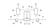
- FIG. 1 is a schematic diagram illustrating an example of a low-temperature water electrolysis apparatus according to the present embodiment.
- FIG. 2 is a schematic diagram showing an example of a PEM water electrolysis device.
- FIG. 3 is a schematic diagram illustrating an example of an alkaline water electrolysis apparatus.
- FIG. 4 is a schematic diagram showing an example of an AEM type water electrolysis apparatus.
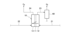
- FIG. 5 is a schematic diagram showing an example of a medium- to high-temperature steam electrolysis device according to this embodiment.
- FIG. 6 is a schematic diagram showing an example of an SOEC type water electrolysis device.
- FIG. 7 is a schematic diagram showing an example of a PCEC water electrolysis device.
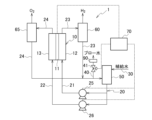
- FIG. 8 is a schematic diagram showing an example of an electrolysis device including a permeation device.
- the determination method determines whether or not a target molecule is an electrolytic hydrogen-containing molecule.
- An electrolytic hydrogen-containing molecule includes hydrogen molecules produced by water electrolysis or molecules produced using the above-mentioned hydrogen molecules as a raw material. Water electrolysis can be performed using renewable energy. When a target molecule is an electrolytic hydrogen-containing molecule and water is electrolyzed using renewable energy, it can be determined whether or not the target molecule is derived from renewable energy.
- the target molecule is a molecule that contains the hydrogen element.
- the target molecule may be a hydrogen molecule, ammonia, or a hydrocarbon.
- the electrolytic hydrogen-containing molecule may be a hydrogen molecule, ammonia, or a hydrocarbon.
- Hydrogen and ammonia can be used as fuels that do not contain carbon. Therefore, instead of fossil fuels, hydrogen and ammonia can be used as fuels derived from renewable energy.
- hydrocarbons can be produced using carbon dioxide as a raw material. Therefore, carbon dioxide contained in the exhaust gas from a factory can be captured, and the captured carbon dioxide can be effectively used as a raw material for chemical products.
- Hydrogen molecules can be produced by water electrolysis. Water electrolysis can be performed by an electrolysis device described below.
- the hydrogen molecules may be hydrogen gas.
- Molecules such as ammonia and hydrocarbons can be produced using hydrogen molecules produced by water electrolysis as a raw material.
- Ammonia can be produced, for example, by the Haber-Bosch process using hydrogen molecules as a raw material.
- Hydrocarbons may contain at least one of methane and olefins.
- Methane can be produced by a methanation reaction using hydrogen molecules as a raw material.
- Olefins alkenes
- Fischer-Tropsch reaction using hydrogen molecules as a raw material.
- Hydrogen is the most abundant isotope of hydrogen in nature.
- Deuterium is a stable isotope of hydrogen.
- Tritium is a radioactive isotope and occurs in very small amounts in nature.
- the target molecule when the abundance ratio of deuterium to protium in the target molecule is equal to or less than a predetermined threshold value that is lower than the abundance ratio of deuterium to protium in nature, the target molecule is determined to be an electrolytic hydrogen-containing molecule.
- Electrolytic hydrogen-containing molecules produced by the method described below have a lower abundance ratio of deuterium. Therefore, when the abundance ratio of deuterium in the target molecule is lower than the abundance ratio of deuterium in nature, the target molecule can be determined to be an electrolytic hydrogen-containing molecule.
- deuterium a stable isotope of hydrogen
- the target molecule is an electrolytic hydrogen-containing molecule.
- deuterium molecules such as HD and D2 have a slower reaction rate than light hydrogen molecules such as H2 . Therefore, the abundance ratio of deuterium to light hydrogen in the hydrogen molecule obtained by water electrolysis using this reaction rate difference is smaller than the abundance ratios of HDO and D2O to H2O in the electrolytic cell supply water.
- the target molecule is an electrolytic hydrogen-containing molecule.
- the ratio of deuterium to protium in hydrogen molecules obtained by water electrolysis as described above is smaller than the ratio of deuterium to protium in nature. Therefore, hydrogen-containing molecules such as ammonia or hydrocarbons produced using hydrogen molecules produced by water electrolysis as a raw material also have the same ratio of deuterium as the hydrogen molecules.
- the ratio of deuterium to protium in hydrogen obtained by steam reforming of fossil fuels such as natural gas is equivalent to the ratio of deuterium to protium in nature. Therefore, the ratio of deuterium to protium in hydrogen-containing molecules such as ammonia or hydrocarbons produced using hydrogen molecules that have a smaller hydrogen abundance ratio than the natural hydrogen abundance ratio also has a smaller ratio of deuterium than the natural deuterium abundance ratio.
- the abundance ratio of deuterium to protium in a target molecule can be obtained by calculating the molar ratio of deuterium to protium contained in the target molecule.
- the abundance ratio of deuterium to protium in a target molecule is the molar ratio of molecules that contain at least one deuterium atom to molecules that consist only of protium atoms among the molecules contained in the target molecule.
- the abundance ratio of deuterium can be obtained using a mass spectrometer.
- the abundance ratio of deuterium may also be obtained using a mass spectrometer combined with a separation device such as a gas chromatograph.
- the abundance ratio of deuterium can also be obtained using a combination of a gas chromatograph and a detector such as a TCD (Thermal Conductivity Detector).
- the abundance ratio of deuterium to hydrogen in nature is said to be 184 ppm or less. Therefore, the abundance ratio of deuterium to hydrogen in nature may be, for example, 184 ppm or less.
- the abundance ratio of deuterium to hydrogen in nature may also be the abundance ratio of deuterium to hydrogen in Vienna Standard Mean Seawater (VSMOW).
- VSMOW Vienna Standard Mean Seawater
- the abundance ratio of deuterium to hydrogen in Vienna Standard Mean Seawater is approximately 155 ppm.
- the threshold value may be smaller than the abundance ratio of deuterium to protium in nature.
- the threshold value may be, for example, 120 ppm, 100 ppm, 80 ppm, 60 ppm, 40 ppm, 20 ppm, or 10 ppm. When the abundance ratio of deuterium is small, it is easy to determine whether the target molecule is an electrolytic hydrogen-containing molecule.
- the threshold value may be greater than 0 ppm.
- the determination method is a method for determining whether a target molecule containing hydrogen elements is an electrolytic hydrogen-containing molecule that includes hydrogen molecules produced by water electrolysis or molecules produced using the above-mentioned hydrogen molecules as a raw material.
- This determination method determines that the target molecule is an electrolytic hydrogen-containing molecule when the abundance ratio of deuterium to protium in the target molecule is equal to or less than a predetermined threshold value that is smaller than the abundance ratio of deuterium to protium in nature.
- the determination method according to this embodiment makes it possible to determine that the target molecule is a molecule produced using renewable energy.
- the method according to this embodiment is particularly useful as a sampling inspection at the time of receiving goods. Since the method according to this embodiment is useful as a sampling inspection, the analysis results of the produced electrolytic hydrogen-containing molecules can be attached to the product as a quality record to ensure quality.
- the method according to this embodiment may be a quality assurance method for assuring that a target molecule containing hydrogen element is an electrolytic hydrogen-containing molecule that contains hydrogen molecules produced by water electrolysis or molecules produced using hydrogen molecules as a raw material.
- the quality assurance method may assure that the target molecule is an electrolytic hydrogen-containing molecule when the abundance ratio of deuterium to protium in the target molecule is equal to or less than a predetermined threshold value that is lower than the abundance ratio of deuterium to protium in nature.
- the quality assurance method of this embodiment when the target molecule is received, the ratio of deuterium to proton in the target molecule is analyzed, thereby confirming the quality of the target molecule. Furthermore, according to the quality assurance method of this embodiment, the ratio of deuterium to proton in the target molecule is analyzed before the target molecule is shipped, thereby guaranteeing the quality of the target molecule to be shipped.
- the quality of the target molecule may be attached to the product as a warranty or label.
- the determination method may be performed by a determination device having a determination unit.
- the determination device may also have, for example, a measurement unit, a determination unit, and an output unit.
- the measurement unit may include a device that measures the abundance ratio of deuterium to protium in the target molecule.
- the measurement unit may include, for example, a mass spectrometer.
- the measurement unit may also be a combination of a mass spectrometer and a separation device such as a gas chromatograph, or may include a combination of a gas chromatograph and a detector.
- the determination unit determines whether the target molecule containing hydrogen element is an electrolytic hydrogen-containing molecule containing hydrogen molecules generated by water electrolysis or molecules generated using hydrogen molecules as a raw material.
- the determination unit determines that the target molecule is an electrolytic hydrogen-containing molecule when the abundance ratio of deuterium to protium of the target molecule is equal to or less than a predetermined threshold value that is smaller than the abundance ratio of deuterium to protium in nature.
- the determination unit may determine that the target molecule is an electrolytic hydrogen-containing molecule when the abundance ratio of deuterium to protium of the target molecule acquired by the measurement unit is equal to or less than a predetermined threshold value that is smaller than the abundance ratio of deuterium to protium in nature.
- the signal of the data of the deuterium abundance ratio output from the measurement unit is output to the determination unit, and the determination unit may acquire the data output from the measurement unit.
- the determination unit may be, for example, a computer including a CPU (central processing unit) and a memory.
- the CPU can read the determination program stored in the memory and determine whether the target molecule is an electrolytic hydrogen-containing molecule based on the abundance ratio of deuterium to protium of the target molecule acquired by the measurement unit and the threshold value.
- the output unit outputs the determination result determined by the determination unit. Examples of the output unit include a monitor and a printer.
- the output unit can output a determination result to the output unit, for example, that "the target molecule is an electrolytic hydrogen-containing molecule" or "the target molecule is not an electrolytic hydrogen-containing molecule.”
- the electrolysis device according to the present embodiment can perform the water electrolysis described in the above embodiment.
- the electrolysis device according to the present embodiment may be a low-temperature water electrolysis device or a medium- to high-temperature water vapor electrolysis device.
- the electrolysis apparatus 1 includes an electrolytic cell 10, a circulation flow path 20, a water supply flow path 30, and a drainage flow path 40.
- the electrolytic cell 10 electrolyzes water. Hydrogen and oxygen are produced by the electrolysis of water.
- the electrolysis method in the electrolytic cell 10 may be alkaline water electrolysis, solid polymer water electrolysis, or a combination of these.
- the electrolysis method in the electrolytic cell 10 may be PEM (Proton Exchange Membrane) water electrolysis, alkaline water electrolysis, AEM (Anion Exchange Membrane) water electrolysis, etc.
- the electrolytic cell 10 includes a membrane 11, a cathode 12, and an anode 13.
- the electrolytic cell 10 includes a DC power source (not shown) electrically connected to the cathode 12 and the anode 13, and water is electrolyzed by applying a voltage to the cathode 12 and the anode 13.
- water electrolyzed in the electrolytic cell 10 circulates. Pure water is usually used as the water supplied to the electrolysis device 1, so by circulating the water, the pure water can be effectively utilized.
- a water supply flow path 30 and a drainage flow path 40 are connected to the circulation flow path 20.
- the water supply flow path 30 supplies pure water to the circulation flow path 20.
- the pure water may have an electrical resistivity of 0.1 ⁇ cm or more at 25°C.
- the electrical resistivity of the pure water may be 20 M ⁇ cm or less, 10 M ⁇ cm or less, or 1.5 M ⁇ cm or less.
- the drainage flow path 40 drains part or all of the water in the circulation flow path 20 downstream of the electrolytic cell 10 and upstream of the water supply via the water supply flow path 30.
- a flow rate adjustment device 41 that adjusts the amount of water drained from the circulation flow path 20 may be provided in the drainage flow path 40.
- the flow rate regulator 41 can regulate the flow rate of water flowing through the drainage flow path 40, and can regulate the amount of water in the circulation flow path 20 that is discharged from the drainage flow path 40 by the flow rate regulator 41. This allows the deuterium abundance ratio of the hydrogen molecules generated in the electrolytic cell 10 to be regulated.
- the flow rate regulator 41 may be a flow rate control valve or the like.
- the circulation flow path 20 may include a cathode side water supply pipe 21, an anode side water supply pipe 22, a cathode side drain pipe 23, and an anode side drain pipe 24.
- the electrolysis device 1 may include an electrolyte water supply tank 50 provided in the circulation flow path 20, a hydrogen gas-liquid separator 60 provided in the circulation flow path 20, and an oxygen gas-liquid separator 65 provided in the circulation flow path 20.
- a pump 25 is provided in the cathode side water supply pipe 21.
- a pump 26 is provided in the anode side water supply pipe 22.
- a hydrogen gas-liquid separator 60 is provided in the cathode side drain pipe 23.
- An oxygen gas-liquid separator 65 is provided in the anode side drain pipe 24.
- the electrolyte water supply tank 50 is supplied with make-up water via the water supply passage 30, and stores water for electrolysis in the electrolytic cell 10.
- the outlet of the electrolyte water supply tank 50 is connected to the inlet on the cathode 12 side of the electrolytic cell 10 via the cathode side water supply pipe 21.
- water is supplied from the electrolyte water supply tank 50 to the cathode 12 side of the electrolytic cell 10.
- the outlet of the electrolyte water supply tank 50 is connected to the inlet on the anode 13 side of the electrolytic cell 10 via the anode side water supply pipe 22.
- water is supplied from the electrolyte water supply tank 50 to the anode 13 side of the electrolytic cell 10.
- the outlet on the cathode 12 side of the electrolytic cell 10 is connected to the inlet of the electrolyte water supply tank 50 via the cathode side drain pipe 23.
- a hydrogen gas-liquid separator 60 is provided in the cathode side drain pipe 23.
- the outlet on the anode 13 side of the electrolytic cell 10 is connected to the inlet of the electrolyte water supply tank 50 via the anode side drain pipe 24.
- An oxygen gas-liquid separator 65 is provided in the anode side drain pipe 24.
- the water that has passed through the electrolytic cell 10 is supplied to the hydrogen gas-liquid separator 60 together with the hydrogen gas generated at the cathode 12, and is supplied to the oxygen gas-liquid separator 65 together with the oxygen gas generated at the anode 13.
- the hydrogen gas-liquid separator 60 hydrogen produced by electrolysis in the cathode 12 is separated from water discharged without being electrolyzed in the electrolytic cell 10.
- the hydrogen separated in the hydrogen gas-liquid separator 60 is recovered and stored, for example, in a storage tank. Meanwhile, the water separated in the hydrogen gas-liquid separator 60 is supplied to the electrolyte water tank 50 through the cathode side drain pipe 23.
- oxygen generated by electrolysis in the anode 13 is separated from water discharged without being electrolyzed in the electrolytic cell 10.
- the oxygen separated in the oxygen-gas-liquid separator 65 is stored, for example, in a storage tank. Meanwhile, the water separated in the oxygen-gas-liquid separator 65 is supplied to the electrolyte water tank 50 through the anode-side drain pipe 24.
- the electrolyte water supply tank 50 stores water that is not electrolyzed in the electrolytic cell 10 and is discharged from the electrolytic cell 10, and the water circulates between the electrolytic cell 10 and the electrolyte water supply tank 50.
- the electrolysis device 1 may include a control unit 70.
- the control unit 70 may be electrically connected to at least one selected from the group consisting of the electrolysis cell 10, the pump 25, the pump 26, and the flow rate adjustment device 41.
- the control unit 70 may control at least one of the applied voltage and the current density of the electrolysis cell 10.
- the control unit 70 may control the flow rate of water supplied to the electrolysis cell 10 by operating at least one of the pump 25 and the pump 26.
- the control unit 70 may control the flow rate of water in the circulation flow path 20 discharged from the discharge flow path 40 by operating the flow rate adjustment device 41. By these controls, the ratio of deuterium to protium in the hydrogen molecules generated in the electrolysis cell 10 can be adjusted.
- PEM type water electrolysis device First, an example of a PEM water electrolysis apparatus will be described with reference to Fig. 2.
- water is supplied to the anode 13 through an anode-side water supply pipe 22 of an electrolytic cell 10.
- oxygen and hydrogen ions (H + ) are produced from the water by electrolysis.
- the membrane 11 is a PEM, and the hydrogen ions (H + ) permeate the membrane 11 and move from the anode 13 side to the cathode 12 side.
- hydrogen gas is produced from the hydrogen ions that have permeated the membrane 11.
- Water may be supplied to the cathode 12 side through a cathode-side water supply pipe 21, or water may not be supplied through the cathode-side water supply pipe 21.
- the rate at which deuterium ions (D + ) permeate the membrane 11 is slower than the rate at which light hydrogen ions (H + ) permeate the membrane 11. Also, the rate at which D + is produced from HDO and D 2 O at the anode 13 is slower than the rate at which H + is produced from H 2 O. Therefore, at the cathode 12, the amount of deuterium gas such as HD gas and D 2 gas produced is less than the amount of light hydrogen gas produced. Therefore, the abundance ratio of deuterium to light hydrogen in the hydrogen molecules produced by the PEM water electrolysis device is smaller than the abundance ratio of deuterium to light hydrogen in the water supplied to the electrolysis cell 10.
- Alkaline water electrolysis device Next, an example of an alkaline water electrolysis apparatus will be described with reference to FIG. 3.
- water is supplied to the cathode 12 and the anode 13 of the electrolysis cell 10 through the cathode side water supply pipe 21 and the anode side water supply pipe 22, respectively.
- hydrogen and hydroxide ions (OH ⁇ ) are generated from water by electrolysis.
- the hydroxide ions (OH ⁇ ) permeate the membrane 11 and move from the cathode 12 side to the anode 13 side.
- oxygen is generated from the hydroxide ions (OH ⁇ ) that have permeated the membrane 11.
- the membrane 11 is a diaphragm, and the diaphragm may contain at least one selected from the group consisting of polysulfone, PTFE (polytetrafluoroethylene), asbestos, polyolefin, and anion exchange membrane (AEM).
- the anion exchange membrane may be a resin having a quaternary ammonium group and an imidazolium group.
- the alkaline water passing through the electrolysis cell 10 may contain an aqueous solution of an alkali metal hydroxide.
- the alkali metal hydroxide may include at least one of sodium hydroxide and potassium hydroxide.
- the rate at which OD - , HD gas, and D2 gas are produced from HDO and D2O in the cathode 12 is slower than the rate at which OH - and H2 gas are produced from H2O . Therefore, the amount of deuterium gas such as HD gas and D2 gas produced in the cathode 12 is smaller than the amount of light hydrogen gas produced. Therefore, the abundance ratio of deuterium to light hydrogen in the hydrogen molecules produced in the alkaline water electrolysis apparatus is smaller than the abundance ratio of deuterium to light hydrogen in the water supplied to the electrolytic cell 10.
- FIG. 4 An example of an AEM water electrolysis apparatus will be described with reference to Fig. 4.
- water is supplied to the anode 13 of the electrolysis cell 10 through the anode-side water supply pipe 22.
- the water permeates the membrane 11, which is an AEM, and moves from the anode 13 side to the cathode 12 side.
- hydrogen and hydroxide ions (OH - ) are generated from the water that has permeated the membrane 11 by electrolysis.
- the hydroxide ions (OH - ) generated in the cathode 12 permeate the membrane 11 and move from the cathode 12 side to the anode 13 side.
- oxygen and water are generated from the hydroxide ions (OH - ) that have permeated the membrane 11.
- Water may be supplied to the cathode 12 side through the cathode-side water supply pipe 21, or water may not be supplied through the cathode-side water supply pipe 21.
- the rate at which HDO and D2O permeate the membrane 11 is slower than the rate at which H2O permeates the membrane 11. Also, the rate at which HD gas and D2 gas are produced from HDO and D2O at the cathode 12 is slower than the rate at which H2 gas is produced from H2O . Therefore, at the cathode 12, the amount of deuterium gas such as HD gas and D2 gas produced is less than the amount of light hydrogen gas produced. Therefore, the abundance ratio of deuterium to light hydrogen in the hydrogen molecules produced by the AEM water electrolysis apparatus is smaller than the abundance ratio of deuterium to light hydrogen in the water supplied to the electrolysis cell 10.
- the electrolysis method in the electrolysis cell 10 may be SOEC (Solid Oxide Electrolysis Cell) type water electrolysis, PCEC (Protonic Ceramic Electrolysis Cell) type water electrolysis, or a combination of these.
- the electrolysis device 1 according to this embodiment further includes a heat exchanger 80 provided in the circulation flow path 20.
- the electrolysis device 1 is similar to the low-temperature water electrolysis device shown in Fig. 1, and therefore description thereof will be omitted.
- the heat exchanger 80 exchanges heat between the water supplied to the electrolytic cell 10 and the water discharged from the electrolytic cell 10.
- the heat exchanger 80 may include a first heat exchanger provided across the cathode side water supply pipe 21 and the cathode side drain pipe 23, and a second heat exchanger provided across the anode side water supply pipe 22 and the anode side drain pipe 24.
- the first heat exchanger can exchange heat between the water supplied to the cathode 12 side of the electrolytic cell 10 and the water discharged from the cathode 12 side of the electrolytic cell 10.
- the second heat exchanger can exchange heat between the water supplied to the anode 13 side of the electrolytic cell 10 and the water discharged from the anode 13 side of the electrolytic cell 10.
- a heater (not shown) for heating the water supplied to the electrolytic cell 10 may be provided in at least one of the cathode side water supply pipe 21 and the anode side water supply pipe 22.
- FIG. 6 An example of an SOEC water electrolysis apparatus will be described with reference to Fig. 6.
- a cathode 12 of an electrolytic cell 10 through a cathode-side water supply pipe 21.
- hydrogen gas and oxygen ions (O 2- ) are produced from the water vapor by electrolysis.
- the oxygen ions (O 2- ) permeate the membrane 11 and move from the cathode 12 side to the anode 13 side.
- oxygen gas is produced from the oxygen ions (O 2- ) that have permeated the membrane 11.
- the rate at which HD gas and D2 gas are produced from HDO and D2 O in the cathode 12 is slower than the rate at which H2 gas is produced from H2 O. Therefore, the amount of deuterium gas such as HD gas and D2 gas produced in the cathode 12 is smaller than the amount of light hydrogen gas produced. Therefore, the abundance ratio of deuterium to light hydrogen in the hydrogen molecules produced in the SOEC water electrolysis apparatus is smaller than the abundance ratio of deuterium to light hydrogen in the water supplied to the electrolytic cell 10.
- PCEC type water electrolysis device Next, an example of a PCEC water electrolysis apparatus will be described with reference to Fig. 7.
- water vapor is supplied to the anode 13 through the anode-side water supply pipe 22.
- oxygen gas and hydrogen ions (H + ) are produced from the water vapor by electrolysis.
- the hydrogen ions (H + ) permeate the membrane 11 and move from the anode 13 side to the cathode 12 side.
- hydrogen gas is produced from the hydrogen ions (H + ) that have permeated the membrane 11.
- the rate at which deuterium ions (D + ) permeate the membrane 11 is slower than the rate at which light hydrogen ions (H + ) permeate the membrane 11. Also, the rate at which D + is produced from HDO and D 2 O at the anode 13 is slower than the rate at which H + is produced from H 2 O. Therefore, at the cathode 12, the amount of deuterium gas such as HD gas and D 2 gas produced is less than the amount of light hydrogen gas produced. Therefore, the abundance ratio of deuterium to light hydrogen in the hydrogen molecules produced by the PCEC water electrolysis device is smaller than the abundance ratio of deuterium to light hydrogen in the water supplied to the electrolysis cell 10.
- the abundance ratio of deuterium to light hydrogen in the generated hydrogen molecules is smaller than the abundance ratio of deuterium to light hydrogen in the water supplied to the electrolytic cell 10.
- the abundance ratio of deuterium in the water discharged from the electrolytic cell 10 is larger than the abundance ratio of deuterium in the water supplied to the electrolytic cell 10.
- the abundance ratio of deuterium in the water flowing in the circulation flow path 20 is diluted and becomes smaller, and the abundance ratio of deuterium in the hydrogen molecules generated in the electrolytic cell 10 is further decreased. Therefore, the abundance ratio of deuterium to light hydrogen in the hydrogen molecules generated by the water electrolysis in the electrolytic cell 10 is smaller than the abundance ratio of deuterium to light hydrogen in nature.
- the water supplied to the electrolytic cell 10 may be alkaline water, and the electrolysis device 1 may further include a membrane separation device 90.
- the membrane separation device 90 may be provided in the drainage flow path 40.
- the membrane separation device 90 may include a permeable membrane that selectively allows water in the alkaline water to pass through.
- the semipermeable membrane selectively allows water in the alkaline water to pass through.
- the semipermeable membrane allows water in the alkaline water to pass through, but does not allow metal ions such as sodium ions and potassium ions to pass through. Therefore, it is possible to discharge only water without discharging alkaline water outside the circulation flow path 20.
- the semipermeable membrane may include at least one selected from the group consisting of a flat membrane, a hollow fiber membrane, and a spiral membrane.
- the pore size of the semipermeable membrane may be large enough to allow water molecules to pass through but not allow sodium ions and the like in the treated water to pass through.
- the pore size of the semipermeable membrane may be 0.5 nm or more, or 1 nm or more.
- the pore size of the semipermeable membrane may be 10 nm or less, 5 nm or less, or 2 nm or less.
- the semipermeable membrane may be a reverse osmosis membrane (RO membrane).
- the semipermeable membrane may include at least one selected from the group consisting of cellulose acetate, polyacrylonitrile, polysulfone, polyethersulfone, polyethylene, polypropylene, polyvinylidene fluoride, and ceramic.
- the water utilization rate is the volume ratio of the amount of electrolysis-consumed water to the amount of water supplied to the electrolysis cell.
- the electrolysis-cell supply water is water supplied to the electrolysis cell 10 through the cathode-side water supply pipe 21 and the anode-side water supply pipe 22.
- the electrolysis-consumed water is water consumed by electrolysis in the electrolysis cell 10.
- the separation factor is a value expressed by the following formula:
- ⁇ is a separation coefficient
- [D] L is the abundance ratio of deuterium to light hydrogen in the electrolytic cell supply water
- [D] G is the abundance ratio of deuterium to light hydrogen in the hydrogen gas (hydrogen molecules) generated in the electrolytic cell 10.
- the separation factor can be controlled by using the applied voltage and current density, which are the operating conditions of the electrolytic cell 10, as the manipulated variables.
- the smaller the applied voltage the smaller the ratio of deuterium to light hydrogen in the hydrogen molecules produced.
- the smaller the current density the smaller the ratio of deuterium to light hydrogen in the hydrogen molecules produced.
- the separation factor can also be controlled by selecting the metal species of the electrode catalyst. Separation factors tend to increase in the following order: Cu>Fe>Ni>Ag>Au>Pt>Sn.
- the blow ratio is the volume ratio of the flow rate of blown water to the flow rate of produced water.
- the produced water is water that is not electrolyzed in the electrolytic cell 10 and is discharged from the electrolytic cell 10.
- the blown water is water that is discharged from the drainage flow path 40.
- the flow rate is the amount of water per unit time.
- the amount of hydrogen gas generated is the amount of hydrogen gas (hydrogen molecules) generated by electrolysis in the electrolytic cell 10.
- make-up water is pure water supplied to the circulation flow path 20 through the water supply flow path 30.
- the ratio of deuterium to hydrogen in the pure water is set to 150 ppm.
- the electrolytic cell supply water is water supplied to the electrolytic cell 10, as described above.
- the electrolytic cell supply water is a mixture of make-up water and water that is circulated in the circulation flow path 20 without being discharged as blow water.
- the ratio of deuterium to hydrogen in the electrolytic cell supply water is greater than the ratio of deuterium to hydrogen in the make-up water.
- the ratio of deuterium to light hydrogen in the hydrogen gas generated in the electrolytic cell 10 can be controlled by adjusting the operating conditions of the electrolysis device. Specifically, the lower the water utilization rate, the more the deuterium ratio can be reduced. Also, the larger the separation factor, the more the deuterium ratio can be reduced. Also, the higher the blow ratio, the more the deuterium ratio can be reduced.
- At least one selected from the group consisting of water utilization rate, separation factor, and blow ratio may be controlled.
- the water utilization rate is the ratio of the amount of water consumed by electrolysis in the electrolytic cell 10 to the amount of water supplied to the electrolytic cell.
- the separation factor is the ratio of the amount of deuterium to protium in the water supplied to the electrolytic cell 10 to the amount of deuterium to protium in the hydrogen molecules generated in the electrolytic cell 10.
- the blow ratio is the ratio of the flow rate of water discharged in the drainage process to the flow rate of water discharged from the electrolytic cell 10.
- the deuterium abundance ratio of the target molecule is measured and the deuterium abundance ratio of the hydrogen molecule is within the range calculated based on the operating conditions in Table 1, it can be easily determined that the target molecule is an electrolytic hydrogen-containing molecule. In addition, the quality of the target molecule can be guaranteed by checking against the deuterium abundance ratio specifications issued by the manufacturer of the renewable energy-derived fuel or raw material.
- the electrolysis device 1 includes an electrolysis cell 10 that electrolyzes water, a circulation flow path 20 through which the water electrolyzed in the electrolysis cell 10 circulates, and a water supply flow path 30 that supplies pure water to the circulation flow path 20.
- the electrolysis device 1 includes a drainage flow path 40 that drains some or all of the water in the circulation flow path 20, downstream of the electrolysis cell 10 and upstream of the water supply via the water supply flow path 30.
- the abundance ratio of deuterium to protium in the hydrogen molecules generated by water electrolysis in the electrolysis cell 10 is smaller than the abundance ratio of deuterium to protium in nature.
- the electrolysis method includes an electrolysis step of electrolyzing water in an electrolytic cell 10, and a water supply step of supplying pure water to a circulation flow path 20 that circulates the water electrolyzed in the electrolytic cell 10.
- the electrolysis method also includes a drainage step of draining some or all of the water in the circulation flow path 20 downstream of the electrolytic cell 10 and upstream of the water supplied in the water supply step.
- the abundance ratio of deuterium to protium in the hydrogen molecules generated by water electrolysis in the electrolytic cell 10 is smaller than the abundance ratio of deuterium to protium in nature.
- water is electrolyzed in the electrolytic cell 10.
- the ratio of deuterium to hydrogen in the hydrogen molecules generated in the electrolytic cell 10 is smaller than the ratio of deuterium to hydrogen in the water supplied to the electrolytic cell 10.
- the ratio of deuterium to hydrogen in the water discharged from the electrolytic cell 10 is larger than the ratio of deuterium to hydrogen in the water supplied to the electrolytic cell 10.
- a part or all of the water in the circulation flow path 20 is drained by the drainage flow path 40, and pure water is supplied to the circulation flow path 20 by the water supply flow path 30.
- the ratio of deuterium to hydrogen in the water flowing in the circulation flow path 20 is diluted and becomes smaller, and the ratio of deuterium to hydrogen in the hydrogen molecules generated in the electrolytic cell 10 is further reduced. Therefore, the ratio of deuterium to hydrogen in the hydrogen molecules generated by water electrolysis in the electrolytic cell 10 is smaller than the ratio of deuterium to hydrogen in nature.
- the ratio of deuterium to protium in the hydrogen molecules can be reduced compared to when the water in the circulation flow path 20 is not drained.
- the ratio of deuterium to protium in the generated molecules can be reduced.
- the electrolysis device and electrolysis method according to this embodiment make it easy to confirm whether the target molecule is hydrogen generated by water electrolysis or a molecule generated using the hydrogen as a raw material.
- This disclosure can contribute, for example, to the achievement of Goal 7 of the United Nations-led Sustainable Development Goals (SDGs), "Ensure access to affordable, reliable, sustainable and modern energy for all,” Goal 12, “Ensure sustainable consumption and production patterns,” and Goal 13, “Take urgent action to combat climate change and its impacts.”
- SDGs Sustainable Development Goals
- Electrolysis device 10 Electrolysis cell 20 Circulation flow path 30 Water supply flow path 40 Wastewater flow path 90 Membrane separation device
Landscapes
- Chemical & Material Sciences (AREA)
- Engineering & Computer Science (AREA)
- Chemical Kinetics & Catalysis (AREA)
- Electrochemistry (AREA)
- Materials Engineering (AREA)
- Metallurgy (AREA)
- Organic Chemistry (AREA)
- Life Sciences & Earth Sciences (AREA)
- Analytical Chemistry (AREA)
- Automation & Control Theory (AREA)
- Physics & Mathematics (AREA)
- Bioinformatics & Computational Biology (AREA)
- Crystallography & Structural Chemistry (AREA)
- Bioinformatics & Cheminformatics (AREA)
- Spectroscopy & Molecular Physics (AREA)
- Computing Systems (AREA)
- Theoretical Computer Science (AREA)
- Sustainable Development (AREA)
- Inorganic Chemistry (AREA)
- Health & Medical Sciences (AREA)
- Food Science & Technology (AREA)
- Medicinal Chemistry (AREA)
- Biochemistry (AREA)
- General Health & Medical Sciences (AREA)
- General Physics & Mathematics (AREA)
- Immunology (AREA)
- Pathology (AREA)
- Electrolytic Production Of Non-Metals, Compounds, Apparatuses Therefor (AREA)
Priority Applications (4)
| Application Number | Priority Date | Filing Date | Title |
|---|---|---|---|
| JP2024519905A JP7708313B2 (ja) | 2022-11-01 | 2023-10-20 | 電解装置、及び電解方法 |
| AU2023373022A AU2023373022A1 (en) | 2022-11-01 | 2023-10-20 | Determination method, quality assurance method, electrolysis device, and electrolysis method |
| DE112023004060.5T DE112023004060T5 (de) | 2022-11-01 | 2023-10-20 | Bestimmungsverfahren, qualitätssicherungsverfahren, elektrolysevorrichtung, und elektrolyseverfahren |
| US19/192,041 US20250259714A1 (en) | 2022-11-01 | 2025-04-28 | Determination method, quality assurance method, electrolysis device, and electrolysis method |
Applications Claiming Priority (2)
| Application Number | Priority Date | Filing Date | Title |
|---|---|---|---|
| JP2022175572 | 2022-11-01 | ||
| JP2022-175572 | 2022-11-01 |
Related Child Applications (1)
| Application Number | Title | Priority Date | Filing Date |
|---|---|---|---|
| US19/192,041 Continuation US20250259714A1 (en) | 2022-11-01 | 2025-04-28 | Determination method, quality assurance method, electrolysis device, and electrolysis method |
Publications (1)
| Publication Number | Publication Date |
|---|---|
| WO2024095800A1 true WO2024095800A1 (ja) | 2024-05-10 |
Family
ID=90930481
Family Applications (1)
| Application Number | Title | Priority Date | Filing Date |
|---|---|---|---|
| PCT/JP2023/038103 Ceased WO2024095800A1 (ja) | 2022-11-01 | 2023-10-20 | 判定方法、品質保証方法、電解装置、及び電解方法 |
Country Status (5)
| Country | Link |
|---|---|
| US (1) | US20250259714A1 (https=) |
| JP (1) | JP7708313B2 (https=) |
| AU (1) | AU2023373022A1 (https=) |
| DE (1) | DE112023004060T5 (https=) |
| WO (1) | WO2024095800A1 (https=) |
Cited By (1)
| Publication number | Priority date | Publication date | Assignee | Title |
|---|---|---|---|---|
| WO2026018535A1 (ja) * | 2024-07-18 | 2026-01-22 | 株式会社日立製作所 | 水電解システム及び水電解システムの運用方法 |
Citations (6)
| Publication number | Priority date | Publication date | Assignee | Title |
|---|---|---|---|---|
| JPS5449983A (en) * | 1977-09-28 | 1979-04-19 | Mitsubishi Heavy Ind Ltd | Controlling method for electrolyte concentration of electrolytic solution |
| JPS6082125A (ja) * | 1983-10-08 | 1985-05-10 | Power Reactor & Nuclear Fuel Dev Corp | 水の電気分解による水素同位体濃縮装置 |
| JP2004191271A (ja) * | 2002-12-13 | 2004-07-08 | Suga Test Instr Co Ltd | 水安定同位体比測定用水電解装置及び水安定同位体比質量分析方法 |
| JP2004337843A (ja) * | 2003-04-25 | 2004-12-02 | Showa Denko Kk | 水素同位体水の濃縮方法及び装置 |
| JP2011043329A (ja) * | 2007-12-14 | 2011-03-03 | Kirin Holdings Co Ltd | 低濃度エタノール試料の同位体比分析方法 |
| JP2015029921A (ja) * | 2013-07-31 | 2015-02-16 | ペルメレック電極株式会社 | 重水の電解濃縮方法 |
-
2023
- 2023-10-20 JP JP2024519905A patent/JP7708313B2/ja active Active
- 2023-10-20 DE DE112023004060.5T patent/DE112023004060T5/de active Pending
- 2023-10-20 WO PCT/JP2023/038103 patent/WO2024095800A1/ja not_active Ceased
- 2023-10-20 AU AU2023373022A patent/AU2023373022A1/en active Pending
-
2025
- 2025-04-28 US US19/192,041 patent/US20250259714A1/en active Pending
Patent Citations (6)
| Publication number | Priority date | Publication date | Assignee | Title |
|---|---|---|---|---|
| JPS5449983A (en) * | 1977-09-28 | 1979-04-19 | Mitsubishi Heavy Ind Ltd | Controlling method for electrolyte concentration of electrolytic solution |
| JPS6082125A (ja) * | 1983-10-08 | 1985-05-10 | Power Reactor & Nuclear Fuel Dev Corp | 水の電気分解による水素同位体濃縮装置 |
| JP2004191271A (ja) * | 2002-12-13 | 2004-07-08 | Suga Test Instr Co Ltd | 水安定同位体比測定用水電解装置及び水安定同位体比質量分析方法 |
| JP2004337843A (ja) * | 2003-04-25 | 2004-12-02 | Showa Denko Kk | 水素同位体水の濃縮方法及び装置 |
| JP2011043329A (ja) * | 2007-12-14 | 2011-03-03 | Kirin Holdings Co Ltd | 低濃度エタノール試料の同位体比分析方法 |
| JP2015029921A (ja) * | 2013-07-31 | 2015-02-16 | ペルメレック電極株式会社 | 重水の電解濃縮方法 |
Cited By (1)
| Publication number | Priority date | Publication date | Assignee | Title |
|---|---|---|---|---|
| WO2026018535A1 (ja) * | 2024-07-18 | 2026-01-22 | 株式会社日立製作所 | 水電解システム及び水電解システムの運用方法 |
Also Published As
| Publication number | Publication date |
|---|---|
| DE112023004060T5 (de) | 2025-07-31 |
| US20250259714A1 (en) | 2025-08-14 |
| JPWO2024095800A1 (https=) | 2024-05-10 |
| JP7708313B2 (ja) | 2025-07-15 |
| AU2023373022A1 (en) | 2025-05-08 |
Similar Documents
| Publication | Publication Date | Title |
|---|---|---|
| Pushkareva et al. | Comparative study of anion exchange membranes for low-cost water electrolysis | |
| JP7136919B2 (ja) | 水素の製造方法 | |
| BR112021011768A2 (pt) | Eletrolisador e método de uso | |
| Sin et al. | Performance recovery of proton exchange membrane electrolyzer degraded by metal cations contamination | |
| IL288368A (en) | A modular electrolyzer stack and process for converting carbon dioxide into gaseous products at increased pressure and at a high conversion rate | |
| RU2718872C2 (ru) | Система обработки воды с использованием устройства для электролиза водного раствора щелочи и щелочного топливного элемента | |
| US20250259714A1 (en) | Determination method, quality assurance method, electrolysis device, and electrolysis method | |
| JP2025504077A (ja) | 電解槽セルの温度制御 | |
| AU2023200744A1 (en) | Electrolysis device and method of controlling electrolysis device | |
| Abu Khalla et al. | Desalination fuel cells with high thermodynamic energy efficiency | |
| KR20250174899A (ko) | 전기분해 공정, 전기분해 셀, 및 플랜트 | |
| Binhazzaa et al. | Impact of water properties on the performance of PEM electrolyzer | |
| WO2024097216A2 (en) | Co2 electrolysis plant | |
| Haug | Experimental and theoretical investigation of gas purity in alkaline water electrolysis | |
| AU2022275141B2 (en) | Hydrogen production system and hydrogen production method | |
| JP7772126B2 (ja) | 判定方法、品質保証方法及び判定装置 | |
| US8709229B2 (en) | Method to prevent sulfur accumulation in membrane electrode assembly | |
| Wen et al. | Electrolyzing Outside the Box: Non‐Traditional Approaches to Electrochemical Water Splitting | |
| Ohiomoba et al. | Electrochemical stripping of CO2 from potassium-based salts to facilitate direct air capture | |
| WO2025111360A1 (en) | Anion exchange membrane carbon oxide electrolyzers and methods of use | |
| Lippert et al. | Neutral water electrolysis unifies green hydrogen and renewable natural gas production from biogas | |
| Mahmoudian et al. | Integrated electrochemically assisted absorbers for the removal of Carbon dioxide | |
| Abdalla et al. | Proof-of-Concept of the Integrated Methanol Reforming-Desalination Fuel Cell System: Effect of CO2 and CO on Cell’s Performance | |
| JP2017087087A (ja) | 水素水製造装置 | |
| Gandu | Extension of dynamic operational range in alkaline water electrolysis process |
Legal Events
| Date | Code | Title | Description |
|---|---|---|---|
| ENP | Entry into the national phase |
Ref document number: 2024519905 Country of ref document: JP Kind code of ref document: A |
|
| 121 | Ep: the epo has been informed by wipo that ep was designated in this application |
Ref document number: 23885560 Country of ref document: EP Kind code of ref document: A1 |
|
| WWE | Wipo information: entry into national phase |
Ref document number: AU2023373022 Country of ref document: AU |
|
| ENP | Entry into the national phase |
Ref document number: 2023373022 Country of ref document: AU Date of ref document: 20231020 Kind code of ref document: A |
|
| WWE | Wipo information: entry into national phase |
Ref document number: 112023004060 Country of ref document: DE |
|
| WWP | Wipo information: published in national office |
Ref document number: 112023004060 Country of ref document: DE |
|
| 122 | Ep: pct application non-entry in european phase |
Ref document number: 23885560 Country of ref document: EP Kind code of ref document: A1 |