WO2024095666A1 - 無方向性電磁鋼板の製造方法 - Google Patents
無方向性電磁鋼板の製造方法 Download PDFInfo
- Publication number
- WO2024095666A1 WO2024095666A1 PCT/JP2023/036146 JP2023036146W WO2024095666A1 WO 2024095666 A1 WO2024095666 A1 WO 2024095666A1 JP 2023036146 W JP2023036146 W JP 2023036146W WO 2024095666 A1 WO2024095666 A1 WO 2024095666A1
- Authority
- WO
- WIPO (PCT)
- Prior art keywords
- mass
- steel sheet
- less
- dew point
- group
- Prior art date
- Legal status (The legal status is an assumption and is not a legal conclusion. Google has not performed a legal analysis and makes no representation as to the accuracy of the status listed.)
- Ceased
Links
Images
Classifications
-
- C—CHEMISTRY; METALLURGY
- C22—METALLURGY; FERROUS OR NON-FERROUS ALLOYS; TREATMENT OF ALLOYS OR NON-FERROUS METALS
- C22C—ALLOYS
- C22C38/00—Ferrous alloys, e.g. steel alloys
- C22C38/16—Ferrous alloys, e.g. steel alloys containing copper
-
- C—CHEMISTRY; METALLURGY
- C21—METALLURGY OF IRON
- C21D—MODIFYING THE PHYSICAL STRUCTURE OF FERROUS METALS; GENERAL DEVICES FOR HEAT TREATMENT OF FERROUS OR NON-FERROUS METALS OR ALLOYS; MAKING METAL MALLEABLE, e.g. BY DECARBURISATION OR TEMPERING
- C21D1/00—General methods or devices for heat treatment, e.g. annealing, hardening, quenching or tempering
- C21D1/74—Methods of treatment in inert gas, controlled atmosphere, vacuum or pulverulent material
- C21D1/76—Adjusting the composition of the atmosphere
-
- C—CHEMISTRY; METALLURGY
- C21—METALLURGY OF IRON
- C21D—MODIFYING THE PHYSICAL STRUCTURE OF FERROUS METALS; GENERAL DEVICES FOR HEAT TREATMENT OF FERROUS OR NON-FERROUS METALS OR ALLOYS; MAKING METAL MALLEABLE, e.g. BY DECARBURISATION OR TEMPERING
- C21D6/00—Heat treatment of ferrous alloys
- C21D6/008—Heat treatment of ferrous alloys containing Si
-
- C—CHEMISTRY; METALLURGY
- C21—METALLURGY OF IRON
- C21D—MODIFYING THE PHYSICAL STRUCTURE OF FERROUS METALS; GENERAL DEVICES FOR HEAT TREATMENT OF FERROUS OR NON-FERROUS METALS OR ALLOYS; MAKING METAL MALLEABLE, e.g. BY DECARBURISATION OR TEMPERING
- C21D8/00—Modifying the physical properties of ferrous metals or ferrous alloys by deformation combined with, or followed by, heat treatment
- C21D8/12—Modifying the physical properties of ferrous metals or ferrous alloys by deformation combined with, or followed by, heat treatment during manufacturing of articles with special electromagnetic properties
-
- C—CHEMISTRY; METALLURGY
- C21—METALLURGY OF IRON
- C21D—MODIFYING THE PHYSICAL STRUCTURE OF FERROUS METALS; GENERAL DEVICES FOR HEAT TREATMENT OF FERROUS OR NON-FERROUS METALS OR ALLOYS; MAKING METAL MALLEABLE, e.g. BY DECARBURISATION OR TEMPERING
- C21D8/00—Modifying the physical properties of ferrous metals or ferrous alloys by deformation combined with, or followed by, heat treatment
- C21D8/12—Modifying the physical properties of ferrous metals or ferrous alloys by deformation combined with, or followed by, heat treatment during manufacturing of articles with special electromagnetic properties
- C21D8/1205—Modifying the physical properties of ferrous metals or ferrous alloys by deformation combined with, or followed by, heat treatment during manufacturing of articles with special electromagnetic properties involving particular fabrication steps or treatments of ingots or slabs
-
- C—CHEMISTRY; METALLURGY
- C21—METALLURGY OF IRON
- C21D—MODIFYING THE PHYSICAL STRUCTURE OF FERROUS METALS; GENERAL DEVICES FOR HEAT TREATMENT OF FERROUS OR NON-FERROUS METALS OR ALLOYS; MAKING METAL MALLEABLE, e.g. BY DECARBURISATION OR TEMPERING
- C21D8/00—Modifying the physical properties of ferrous metals or ferrous alloys by deformation combined with, or followed by, heat treatment
- C21D8/12—Modifying the physical properties of ferrous metals or ferrous alloys by deformation combined with, or followed by, heat treatment during manufacturing of articles with special electromagnetic properties
- C21D8/1216—Modifying the physical properties of ferrous metals or ferrous alloys by deformation combined with, or followed by, heat treatment during manufacturing of articles with special electromagnetic properties characterised by the working steps
- C21D8/1222—Hot rolling
-
- C—CHEMISTRY; METALLURGY
- C21—METALLURGY OF IRON
- C21D—MODIFYING THE PHYSICAL STRUCTURE OF FERROUS METALS; GENERAL DEVICES FOR HEAT TREATMENT OF FERROUS OR NON-FERROUS METALS OR ALLOYS; MAKING METAL MALLEABLE, e.g. BY DECARBURISATION OR TEMPERING
- C21D8/00—Modifying the physical properties of ferrous metals or ferrous alloys by deformation combined with, or followed by, heat treatment
- C21D8/12—Modifying the physical properties of ferrous metals or ferrous alloys by deformation combined with, or followed by, heat treatment during manufacturing of articles with special electromagnetic properties
- C21D8/1216—Modifying the physical properties of ferrous metals or ferrous alloys by deformation combined with, or followed by, heat treatment during manufacturing of articles with special electromagnetic properties characterised by the working steps
- C21D8/1233—Cold rolling
-
- C—CHEMISTRY; METALLURGY
- C21—METALLURGY OF IRON
- C21D—MODIFYING THE PHYSICAL STRUCTURE OF FERROUS METALS; GENERAL DEVICES FOR HEAT TREATMENT OF FERROUS OR NON-FERROUS METALS OR ALLOYS; MAKING METAL MALLEABLE, e.g. BY DECARBURISATION OR TEMPERING
- C21D8/00—Modifying the physical properties of ferrous metals or ferrous alloys by deformation combined with, or followed by, heat treatment
- C21D8/12—Modifying the physical properties of ferrous metals or ferrous alloys by deformation combined with, or followed by, heat treatment during manufacturing of articles with special electromagnetic properties
- C21D8/1244—Modifying the physical properties of ferrous metals or ferrous alloys by deformation combined with, or followed by, heat treatment during manufacturing of articles with special electromagnetic properties characterised by the heat treatment
- C21D8/1261—Modifying the physical properties of ferrous metals or ferrous alloys by deformation combined with, or followed by, heat treatment during manufacturing of articles with special electromagnetic properties characterised by the heat treatment following hot rolling
-
- C—CHEMISTRY; METALLURGY
- C21—METALLURGY OF IRON
- C21D—MODIFYING THE PHYSICAL STRUCTURE OF FERROUS METALS; GENERAL DEVICES FOR HEAT TREATMENT OF FERROUS OR NON-FERROUS METALS OR ALLOYS; MAKING METAL MALLEABLE, e.g. BY DECARBURISATION OR TEMPERING
- C21D8/00—Modifying the physical properties of ferrous metals or ferrous alloys by deformation combined with, or followed by, heat treatment
- C21D8/12—Modifying the physical properties of ferrous metals or ferrous alloys by deformation combined with, or followed by, heat treatment during manufacturing of articles with special electromagnetic properties
- C21D8/1244—Modifying the physical properties of ferrous metals or ferrous alloys by deformation combined with, or followed by, heat treatment during manufacturing of articles with special electromagnetic properties characterised by the heat treatment
- C21D8/1272—Final recrystallisation annealing
-
- C—CHEMISTRY; METALLURGY
- C21—METALLURGY OF IRON
- C21D—MODIFYING THE PHYSICAL STRUCTURE OF FERROUS METALS; GENERAL DEVICES FOR HEAT TREATMENT OF FERROUS OR NON-FERROUS METALS OR ALLOYS; MAKING METAL MALLEABLE, e.g. BY DECARBURISATION OR TEMPERING
- C21D9/00—Heat treatment, e.g. annealing, hardening, quenching or tempering, adapted for particular articles; Furnaces therefor
- C21D9/46—Heat treatment, e.g. annealing, hardening, quenching or tempering, adapted for particular articles; Furnaces therefor for sheet metals
-
- C—CHEMISTRY; METALLURGY
- C22—METALLURGY; FERROUS OR NON-FERROUS ALLOYS; TREATMENT OF ALLOYS OR NON-FERROUS METALS
- C22C—ALLOYS
- C22C38/00—Ferrous alloys, e.g. steel alloys
-
- C—CHEMISTRY; METALLURGY
- C22—METALLURGY; FERROUS OR NON-FERROUS ALLOYS; TREATMENT OF ALLOYS OR NON-FERROUS METALS
- C22C—ALLOYS
- C22C38/00—Ferrous alloys, e.g. steel alloys
- C22C38/002—Ferrous alloys, e.g. steel alloys containing In, Mg, or other elements not provided for in one single group C22C38/001 - C22C38/60
-
- C—CHEMISTRY; METALLURGY
- C22—METALLURGY; FERROUS OR NON-FERROUS ALLOYS; TREATMENT OF ALLOYS OR NON-FERROUS METALS
- C22C—ALLOYS
- C22C38/00—Ferrous alloys, e.g. steel alloys
- C22C38/004—Very low carbon steels, i.e. having a carbon content of less than 0,01%
-
- C—CHEMISTRY; METALLURGY
- C22—METALLURGY; FERROUS OR NON-FERROUS ALLOYS; TREATMENT OF ALLOYS OR NON-FERROUS METALS
- C22C—ALLOYS
- C22C38/00—Ferrous alloys, e.g. steel alloys
- C22C38/005—Ferrous alloys, e.g. steel alloys containing rare earths, i.e. Sc, Y, Lanthanides
-
- C—CHEMISTRY; METALLURGY
- C22—METALLURGY; FERROUS OR NON-FERROUS ALLOYS; TREATMENT OF ALLOYS OR NON-FERROUS METALS
- C22C—ALLOYS
- C22C38/00—Ferrous alloys, e.g. steel alloys
- C22C38/008—Ferrous alloys, e.g. steel alloys containing tin
-
- C—CHEMISTRY; METALLURGY
- C22—METALLURGY; FERROUS OR NON-FERROUS ALLOYS; TREATMENT OF ALLOYS OR NON-FERROUS METALS
- C22C—ALLOYS
- C22C38/00—Ferrous alloys, e.g. steel alloys
- C22C38/02—Ferrous alloys, e.g. steel alloys containing silicon
-
- C—CHEMISTRY; METALLURGY
- C22—METALLURGY; FERROUS OR NON-FERROUS ALLOYS; TREATMENT OF ALLOYS OR NON-FERROUS METALS
- C22C—ALLOYS
- C22C38/00—Ferrous alloys, e.g. steel alloys
- C22C38/04—Ferrous alloys, e.g. steel alloys containing manganese
-
- C—CHEMISTRY; METALLURGY
- C22—METALLURGY; FERROUS OR NON-FERROUS ALLOYS; TREATMENT OF ALLOYS OR NON-FERROUS METALS
- C22C—ALLOYS
- C22C38/00—Ferrous alloys, e.g. steel alloys
- C22C38/06—Ferrous alloys, e.g. steel alloys containing aluminium
-
- C—CHEMISTRY; METALLURGY
- C22—METALLURGY; FERROUS OR NON-FERROUS ALLOYS; TREATMENT OF ALLOYS OR NON-FERROUS METALS
- C22C—ALLOYS
- C22C38/00—Ferrous alloys, e.g. steel alloys
- C22C38/10—Ferrous alloys, e.g. steel alloys containing cobalt
-
- C—CHEMISTRY; METALLURGY
- C22—METALLURGY; FERROUS OR NON-FERROUS ALLOYS; TREATMENT OF ALLOYS OR NON-FERROUS METALS
- C22C—ALLOYS
- C22C38/00—Ferrous alloys, e.g. steel alloys
- C22C38/12—Ferrous alloys, e.g. steel alloys containing tungsten, tantalum, molybdenum, vanadium, or niobium
-
- C—CHEMISTRY; METALLURGY
- C22—METALLURGY; FERROUS OR NON-FERROUS ALLOYS; TREATMENT OF ALLOYS OR NON-FERROUS METALS
- C22C—ALLOYS
- C22C38/00—Ferrous alloys, e.g. steel alloys
- C22C38/14—Ferrous alloys, e.g. steel alloys containing titanium or zirconium
-
- C—CHEMISTRY; METALLURGY
- C22—METALLURGY; FERROUS OR NON-FERROUS ALLOYS; TREATMENT OF ALLOYS OR NON-FERROUS METALS
- C22C—ALLOYS
- C22C38/00—Ferrous alloys, e.g. steel alloys
- C22C38/18—Ferrous alloys, e.g. steel alloys containing chromium
- C22C38/34—Ferrous alloys, e.g. steel alloys containing chromium with more than 1.5% by weight of silicon
-
- C—CHEMISTRY; METALLURGY
- C22—METALLURGY; FERROUS OR NON-FERROUS ALLOYS; TREATMENT OF ALLOYS OR NON-FERROUS METALS
- C22C—ALLOYS
- C22C38/00—Ferrous alloys, e.g. steel alloys
- C22C38/18—Ferrous alloys, e.g. steel alloys containing chromium
- C22C38/40—Ferrous alloys, e.g. steel alloys containing chromium with nickel
-
- C—CHEMISTRY; METALLURGY
- C22—METALLURGY; FERROUS OR NON-FERROUS ALLOYS; TREATMENT OF ALLOYS OR NON-FERROUS METALS
- C22C—ALLOYS
- C22C38/00—Ferrous alloys, e.g. steel alloys
- C22C38/18—Ferrous alloys, e.g. steel alloys containing chromium
- C22C38/40—Ferrous alloys, e.g. steel alloys containing chromium with nickel
- C22C38/44—Ferrous alloys, e.g. steel alloys containing chromium with nickel with molybdenum or tungsten
-
- C—CHEMISTRY; METALLURGY
- C22—METALLURGY; FERROUS OR NON-FERROUS ALLOYS; TREATMENT OF ALLOYS OR NON-FERROUS METALS
- C22C—ALLOYS
- C22C38/00—Ferrous alloys, e.g. steel alloys
- C22C38/18—Ferrous alloys, e.g. steel alloys containing chromium
- C22C38/40—Ferrous alloys, e.g. steel alloys containing chromium with nickel
- C22C38/46—Ferrous alloys, e.g. steel alloys containing chromium with nickel with vanadium
-
- C—CHEMISTRY; METALLURGY
- C22—METALLURGY; FERROUS OR NON-FERROUS ALLOYS; TREATMENT OF ALLOYS OR NON-FERROUS METALS
- C22C—ALLOYS
- C22C38/00—Ferrous alloys, e.g. steel alloys
- C22C38/18—Ferrous alloys, e.g. steel alloys containing chromium
- C22C38/40—Ferrous alloys, e.g. steel alloys containing chromium with nickel
- C22C38/48—Ferrous alloys, e.g. steel alloys containing chromium with nickel with niobium or tantalum
-
- C—CHEMISTRY; METALLURGY
- C22—METALLURGY; FERROUS OR NON-FERROUS ALLOYS; TREATMENT OF ALLOYS OR NON-FERROUS METALS
- C22C—ALLOYS
- C22C38/00—Ferrous alloys, e.g. steel alloys
- C22C38/18—Ferrous alloys, e.g. steel alloys containing chromium
- C22C38/40—Ferrous alloys, e.g. steel alloys containing chromium with nickel
- C22C38/50—Ferrous alloys, e.g. steel alloys containing chromium with nickel with titanium or zirconium
-
- C—CHEMISTRY; METALLURGY
- C22—METALLURGY; FERROUS OR NON-FERROUS ALLOYS; TREATMENT OF ALLOYS OR NON-FERROUS METALS
- C22C—ALLOYS
- C22C38/00—Ferrous alloys, e.g. steel alloys
- C22C38/18—Ferrous alloys, e.g. steel alloys containing chromium
- C22C38/40—Ferrous alloys, e.g. steel alloys containing chromium with nickel
- C22C38/52—Ferrous alloys, e.g. steel alloys containing chromium with nickel with cobalt
-
- C—CHEMISTRY; METALLURGY
- C22—METALLURGY; FERROUS OR NON-FERROUS ALLOYS; TREATMENT OF ALLOYS OR NON-FERROUS METALS
- C22C—ALLOYS
- C22C38/00—Ferrous alloys, e.g. steel alloys
- C22C38/60—Ferrous alloys, e.g. steel alloys containing lead, selenium, tellurium, or antimony, or more than 0.04% by weight of sulfur
-
- H—ELECTRICITY
- H01—ELECTRIC ELEMENTS
- H01F—MAGNETS; INDUCTANCES; TRANSFORMERS; SELECTION OF MATERIALS FOR THEIR MAGNETIC PROPERTIES
- H01F1/00—Magnets or magnetic bodies characterised by the magnetic materials therefor; Selection of materials for their magnetic properties
- H01F1/01—Magnets or magnetic bodies characterised by the magnetic materials therefor; Selection of materials for their magnetic properties of inorganic materials
- H01F1/03—Magnets or magnetic bodies characterised by the magnetic materials therefor; Selection of materials for their magnetic properties of inorganic materials characterised by their coercivity
- H01F1/12—Magnets or magnetic bodies characterised by the magnetic materials therefor; Selection of materials for their magnetic properties of inorganic materials characterised by their coercivity of soft-magnetic materials
- H01F1/14—Magnets or magnetic bodies characterised by the magnetic materials therefor; Selection of materials for their magnetic properties of inorganic materials characterised by their coercivity of soft-magnetic materials metals or alloys
- H01F1/147—Alloys characterised by their composition
-
- H—ELECTRICITY
- H01—ELECTRIC ELEMENTS
- H01F—MAGNETS; INDUCTANCES; TRANSFORMERS; SELECTION OF MATERIALS FOR THEIR MAGNETIC PROPERTIES
- H01F1/00—Magnets or magnetic bodies characterised by the magnetic materials therefor; Selection of materials for their magnetic properties
- H01F1/01—Magnets or magnetic bodies characterised by the magnetic materials therefor; Selection of materials for their magnetic properties of inorganic materials
- H01F1/03—Magnets or magnetic bodies characterised by the magnetic materials therefor; Selection of materials for their magnetic properties of inorganic materials characterised by their coercivity
- H01F1/12—Magnets or magnetic bodies characterised by the magnetic materials therefor; Selection of materials for their magnetic properties of inorganic materials characterised by their coercivity of soft-magnetic materials
- H01F1/14—Magnets or magnetic bodies characterised by the magnetic materials therefor; Selection of materials for their magnetic properties of inorganic materials characterised by their coercivity of soft-magnetic materials metals or alloys
- H01F1/147—Alloys characterised by their composition
- H01F1/14766—Fe-Si based alloys
- H01F1/14775—Fe-Si based alloys in the form of sheets
-
- H—ELECTRICITY
- H01—ELECTRIC ELEMENTS
- H01F—MAGNETS; INDUCTANCES; TRANSFORMERS; SELECTION OF MATERIALS FOR THEIR MAGNETIC PROPERTIES
- H01F1/00—Magnets or magnetic bodies characterised by the magnetic materials therefor; Selection of materials for their magnetic properties
- H01F1/01—Magnets or magnetic bodies characterised by the magnetic materials therefor; Selection of materials for their magnetic properties of inorganic materials
- H01F1/03—Magnets or magnetic bodies characterised by the magnetic materials therefor; Selection of materials for their magnetic properties of inorganic materials characterised by their coercivity
- H01F1/12—Magnets or magnetic bodies characterised by the magnetic materials therefor; Selection of materials for their magnetic properties of inorganic materials characterised by their coercivity of soft-magnetic materials
- H01F1/14—Magnets or magnetic bodies characterised by the magnetic materials therefor; Selection of materials for their magnetic properties of inorganic materials characterised by their coercivity of soft-magnetic materials metals or alloys
- H01F1/147—Alloys characterised by their composition
- H01F1/14766—Fe-Si based alloys
- H01F1/14791—Fe-Si-Al based alloys, e.g. Sendust
-
- H—ELECTRICITY
- H01—ELECTRIC ELEMENTS
- H01F—MAGNETS; INDUCTANCES; TRANSFORMERS; SELECTION OF MATERIALS FOR THEIR MAGNETIC PROPERTIES
- H01F1/00—Magnets or magnetic bodies characterised by the magnetic materials therefor; Selection of materials for their magnetic properties
- H01F1/01—Magnets or magnetic bodies characterised by the magnetic materials therefor; Selection of materials for their magnetic properties of inorganic materials
- H01F1/03—Magnets or magnetic bodies characterised by the magnetic materials therefor; Selection of materials for their magnetic properties of inorganic materials characterised by their coercivity
- H01F1/12—Magnets or magnetic bodies characterised by the magnetic materials therefor; Selection of materials for their magnetic properties of inorganic materials characterised by their coercivity of soft-magnetic materials
- H01F1/14—Magnets or magnetic bodies characterised by the magnetic materials therefor; Selection of materials for their magnetic properties of inorganic materials characterised by their coercivity of soft-magnetic materials metals or alloys
- H01F1/16—Magnets or magnetic bodies characterised by the magnetic materials therefor; Selection of materials for their magnetic properties of inorganic materials characterised by their coercivity of soft-magnetic materials metals or alloys in the form of sheets
-
- C—CHEMISTRY; METALLURGY
- C22—METALLURGY; FERROUS OR NON-FERROUS ALLOYS; TREATMENT OF ALLOYS OR NON-FERROUS METALS
- C22B—PRODUCTION AND REFINING OF METALS; PRETREATMENT OF RAW MATERIALS
- C22B9/00—General processes of refining or remelting of metals; Apparatus for electroslag or arc remelting of metals
-
- Y—GENERAL TAGGING OF NEW TECHNOLOGICAL DEVELOPMENTS; GENERAL TAGGING OF CROSS-SECTIONAL TECHNOLOGIES SPANNING OVER SEVERAL SECTIONS OF THE IPC; TECHNICAL SUBJECTS COVERED BY FORMER USPC CROSS-REFERENCE ART COLLECTIONS [XRACs] AND DIGESTS
- Y02—TECHNOLOGIES OR APPLICATIONS FOR MITIGATION OR ADAPTATION AGAINST CLIMATE CHANGE
- Y02P—CLIMATE CHANGE MITIGATION TECHNOLOGIES IN THE PRODUCTION OR PROCESSING OF GOODS
- Y02P10/00—Technologies related to metal processing
- Y02P10/20—Recycling
Definitions
- the present invention relates to a method for manufacturing non-oriented electrical steel sheets, which are primarily used as iron core materials for rotating machines.
- Non-oriented electrical steel sheet is a soft magnetic material mainly used as the iron core material of motors, and a large amount of silicon is added as an alloying element to increase the resistivity of the steel and reduce iron loss.
- Non-oriented electrical steel sheet is often used in industrial induction motors, so so-called low-grade materials with a silicon content of less than 3.0 mass% and a sheet thickness of 0.5 mm to 0.35 mm have been widely used in the past.
- This grade has a relatively low content of silicon, a non-magnetic element, and is characterized by a high magnetic flux density, which is advantageous for reducing the excitation current and copper loss of induction motors.
- the sheet thickness is relatively thick, steel manufacturers also have the advantage of high productivity in continuous rolling and continuous annealing lines and low manufacturing costs.
- non-oriented electrical steel sheets used in the drive motors of electric vehicles are increasingly being replaced by high-grade materials with a silicon content of 3.0 mass% or more and a thickness of 0.3 mm or less, instead of the conventional low-grade materials.
- Such electrical steel sheets for electric vehicles require extremely low iron loss values, and even slight variations in iron loss due to fluctuations in manufacturing conditions have a significant impact on product yield. For this reason, factors that cause variations in iron loss must be eliminated as much as possible.
- Patent Document 1 proposes a technique for reducing iron loss in non-oriented electrical steel sheets, which suppresses variations in iron loss in the sheet width direction by cooling the sheet while keeping the temperature across the entire sheet width within ⁇ 20°C of the temperature at the sheet width center until the temperature at the sheet width center is cooled to 600°C during the cooling process of finish annealing.
- the finishing annealing equipment used to manufacture non-oriented electrical steel sheets is usually equipped with a mechanism for adjusting the flow rate of cooling gas in the sheet width direction, allowing the operator to adjust the gas flow rate in the sheet width direction to equalize the steel sheet temperature.
- a mechanism for adjusting the flow rate of cooling gas in the sheet width direction allowing the operator to adjust the gas flow rate in the sheet width direction to equalize the steel sheet temperature.
- the present invention was made in consideration of the above problems with the conventional technology, and its purpose is to propose a method for stably manufacturing non-oriented electrical steel sheets with lower iron loss than conventional high-grade materials that contain a large amount of Si.
- the inventors conducted extensive research focusing on the effects of impurities contained in the steel material and the finish annealing conditions on iron loss characteristics.
- the reason why the iron loss of high-grade materials with a high Si content could not be sufficiently reduced using conventional technology is because an oxide layer is formed on the steel sheet surface during finish annealing, and that in order to suppress the formation of an oxide layer on the steel sheet surface during the above-mentioned finish annealing, i.e., to suppress the oxidation of the steel sheet surface, it is important to add Cu as a steel component and to properly control the dew point of the furnace atmosphere in the heating zone and soaking zone during finish annealing, which led to the development of the present invention.
- the present invention based on the above findings comprises C: 0.005 mass% or less, Si: 3.0 to 5.0 mass%, Al: 3.0 mass% or less, Mn: 3.0 mass% or less, P: 0.10 mass% or less, S: 0.005 mass% or less, N: 0.005 mass% or less, Cu: 0.01 to 0.5 mass%, and O: 0.005 mass% or less, with the balance being Fe and unavoidable
- the present invention proposes a method for producing a non-oriented electrical steel sheet, in which a slab having a component composition consisting of impurities is hot rolled, hot-rolled sheet annealed, and cold rolled once or two or more times with intermediate annealing in between to form a cold-rolled sheet, and then finish annealed using a continuous annealing facility having a heating zone, a soaking zone, and a cooling zone, characterized in that the dew point D H of the furnace atmosphere in the finish annealing in the region where the steel sheet temperature in the heating zone
- the dew point D S of the furnace atmosphere in the region where the steel sheet temperature in the heating zone is from above 800° C. to the soaking temperature and in the soaking zone is set to ⁇ 40° C. or less, and the dew point D H and the dew point D S are controlled so as to satisfy the relationship D H > D S.
- the method for producing the non-oriented electrical steel sheet of the present invention is characterized in that the dew point DC of the furnace atmosphere in the region of the steel sheet temperature in the cooling zone of the finish annealing from the soaking temperature to 500°C is set to -40°C or lower.
- the slab used in the method for producing the non-oriented electrical steel sheet of the present invention is characterized in that it further contains, in addition to the above-mentioned chemical composition, at least one component selected from the following groups A to J: Group A: at least one of Sn: 0.005-0.20 mass% and Sb: 0.005-0.20 mass%; Group B: at least one of Ca: 0.001-0.010 mass%, Mg: 0.0002-0.005 mass% and REM: 0.001-0.05 mass%; Group C: Cr: 0.01-3.0 mass% D group: Ni: 0.01 to 1 mass% Group E: at least one of Mo: 0-0.050 mass% and B: 0-0.0020 mass% Group F: at least one of Ti: 0-0.010 mass%, Nb: 0-0.0050 mass%, V: 0-0.050 mass%, Pb: 0-0.0020 mass%, Zr: 0-0.050 mass%, Ta: 0-0.0020 mass%, W: 0-0.050 mass%, Se: 0-0.0050 mass%, and Bi
- the slab used in the manufacturing method of the non-oriented electrical steel sheet of the present invention is characterized in that it is a slab having a thickness of 30 mm to 300 mm, which is manufactured by continuously casting molten steel that has been tapped from a converter or electric furnace and has had its composition adjusted.
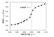
- FIG. 1 is a graph showing the effect of the oxygen coverage on the steel sheet surface after finish annealing on iron loss W 17/200 .
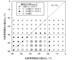
- FIG. 1 is a graph showing the influence of a dew point D H of the furnace atmosphere in a region of the heating zone from 500° C. to 800° C., and a dew point D S of the furnace atmosphere in a region of the heating zone where the steel sheet temperature is from over 800° C. to the soaking temperature and in the soaking zone, on the oxygen weight per unit area of the steel sheet surface in a finish annealing facility.
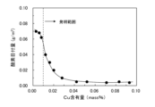
- 1 is a graph showing the effect of Cu content on the oxygen coverage of the steel sheet surface after finish annealing.
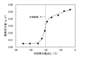
- 1 is a graph showing the effect of the dew point DC of the atmosphere in the cooling zone of the finish annealing equipment on the oxygen coating amount of the steel sheet surface after finish annealing.
- Example 1 A slab containing C: 0.0015 mass%, Si: 3.32 mass%, Mn: 0.51 mass%, P: 0.009 mass%, S: 0.0012 mass%, Al: 0.63 mass%, N: 0.0015 mass%, Cu: 0.05 mass% and O: 0.0012 mass%, with the balance being Fe and inevitable impurities, was hot-rolled to obtain a hot-rolled sheet having a thickness of 1.8 mm. The hot-rolled sheet was then subjected to hot-rolled sheet annealing at a soaking temperature of 980 ° C., pickled, descaled, and cold-rolled to obtain a cold-rolled sheet having a thickness of 0.25 mm.
- the heating rate from 500 ° C. to the soaking temperature in the heating process was set to 15 ° C. / s
- the soaking temperature was set to 980 ° C.
- the soaking time was set to 20 s.
- the furnace atmosphere in the cooling zone was N 2 gas
- the cooling rate from the soaking temperature to 500 ° C. was set to 15 ° C. / s.
- the above heating rate and cooling rate in the finish annealing of the present invention are the average heating rate and average cooling rate, respectively (hereinafter the same).
- the iron loss characteristics of the steel sheet after the final annealing thus obtained were evaluated, it was found that the iron loss value fluctuated greatly depending on the manufacturing timing. This fluctuation was particularly noticeable under the measurement conditions of high magnetic flux density and high frequency. Therefore, in the present invention, the iron loss characteristics were evaluated at the iron loss W 17/200 at the maximum magnetic flux density of 1.7 T and frequency of 200 Hz, where the fluctuation of the iron loss value was particularly noticeable.
- the above iron loss measurement conditions correspond to a state in which the motor excitation current is high and the rotation speed is high, and in the case of an electric vehicle, for example, corresponds to a case in which the motor climbs a slope at a relatively high speed. If the iron loss is high, the temperature of the motor core rises, causing a problem that the rare earth magnet is demagnetized.
- the inventors analyzed the oxygen content of the steel sheet after the finish annealing.
- the oxygen content at the time of tapping (0.0012 mass%) was subtracted from the obtained oxygen content, and the result was converted into the oxygen content (unit: g/ m2 ) per m2 of the steel sheet surface (both sides).
- this oxygen content is referred to as the "oxygen weight”.
- the inventors consider the above phenomenon as follows. Under iron loss measurement conditions in the normal commercial frequency band (W 15/50 , etc.), even if there is a small oxide layer near the surface, this area is not excited much because the magnetic permeability is low, and the effect on iron loss is small. However, under measurement conditions with a high maximum magnetic flux density, the area with low magnetic permeability near the steel sheet surface is also excited, and as the frequency increases, the magnetic flux density on the steel sheet surface tends to increase due to the skin effect. Therefore, with W 17/200 , even a small amount of surface oxide has a significant adverse effect on iron loss.
- the inventors first conducted further investigations, focusing on the finish annealing conditions using a continuous annealing facility that has a heating zone, a soaking zone, and a cooling zone. Specifically, they came up with the idea of separately controlling the atmosphere inside the heating zone and the soaking zone of the above-mentioned finish annealing facility, and conducted experiments to confirm the effects of this.
- the above experimental results are shown in Fig. 2 as the effect of the dew point of the furnace atmosphere in the heating zone and the soaking zone on the oxygen weight per unit area of the steel sheet surface.
- the dew point D H shown in the figure is the dew point of the furnace atmosphere in the region where the steel sheet temperature in the heating zone is from 500°C to 800°C
- the dew point D S is the dew point of the furnace atmosphere in the region where the steel sheet temperature in the heating zone is from over 800°C to the soaking temperature and in the soaking zone.
- the dew point D H of the furnace atmosphere in the region where the steel sheet temperature in the heating zone is from 500° C. to 800° C. is hereinafter referred to as the "dew point D H of the heating zone”
- the dew point D S of the furnace atmosphere in the region where the steel sheet temperature in the heating zone is from over 800° C. to the soaking temperature and in the soaking zone is hereinafter referred to as the "dew point D S of the soaking zone.”
- the inventors consider the reason why the oxygen weight on the steel sheet surface can be reduced when the dew point D H in the heating zone > the dew point D S in the soaking zone is satisfied as follows: When the dew point of the atmosphere in the initial stage of heating is high, very thin Si and Al oxides with high barrier properties are formed on the steel sheet surface, which is believed to actually suppress oxidation in the soaking zone.
- a slab having the same composition as that of the above-mentioned ⁇ Experiment 1> (except Cu) and containing Cu in various amounts varying in the range of 0.003 to 0.5 mass% was hot-rolled to a hot-rolled sheet having a thickness of 1.6 mm, and was subjected to hot-rolled sheet annealing at a soaking temperature of 1020°C, followed by pickling to remove scale.
- the hot-rolled sheet after the pickling was cold-rolled to a thickness of 0.25 mm, and then was subjected to finish annealing with a heating rate of 25°C/s from 500°C to the soaking temperature in the heating process, a soaking temperature of 1010°C, and a soaking time of 10 s.
- the atmosphere in the furnace in the cooling zone was N2 gas, and the cooling rate from the soaking temperature to 500°C was -30°C/s.
- Figure 3 shows the effect of Cu content on the oxygen weight of the steel sheet surface. This figure shows that the addition of Cu at 0.01 mass% or more significantly suppresses oxidation of the steel sheet surface during final annealing.
- the hot-rolled sheet was then subjected to hot-rolled sheet annealing at a soaking temperature of 900 ° C., pickled and descaled, and then cold-rolled to obtain a cold-rolled sheet having a thickness of 0.25 mm.
- the cold-rolled sheet was subjected to finish annealing with a heating rate of 30°C/s from 500°C to the soaking temperature in the heating process, a soaking temperature of 1000°C, and a soaking time of 5s.
- the dew point D H of the heating zone was -35°C
- the dew point D S of the soaking zone was -54°C.
- the atmosphere of the cooling zone was N 2 gas
- the cooling rate from the soaking temperature to 500°C was 15°C/s
- the dew point D C of the furnace atmosphere of the cooling zone was variously changed in the range of 0°C to -70°C.
- C 0.005 mass% or less If a large amount of C is contained in the product plate, it can cause magnetic aging, and when the motor is used at high temperature for a long time, carbides are precipitated, causing an increase in iron loss. Therefore, C is limited to 0.005 mass% or less, and preferably 0.003 mass% or less.
- Si 3.0 to 5.0 mass%
- Silicon is an element that increases the resistivity of steel and reduces iron loss. Since extremely low iron loss is required for electric vehicle drive motors, the addition of 3.0 mass% or more is necessary. However, if the content exceeds 5.0 mass%, cold rolling becomes extremely difficult, so the upper limit is set to 5.0 mass%.
- the preferred range of silicon is 3.5 to 4.5 mass%.
- Mn 3.0 mass% or less Mn is an element that improves hot workability, and also increases the resistivity of steel and reduces iron loss. Therefore, it can be added as necessary. It is preferably 0.01 mass% or more. However, if it exceeds 3.0 mass%, the magnetic flux density decreases and iron loss worsens, so the upper limit is set to 3.0 mass%.
- the preferred range of Mn is 0.3 to 2.0 mass%.
- P 0.10 mass% or less
- P is an element that hardens and embrittles steel, and when the P content exceeds 0.10 mass%, it becomes difficult to perform cold rolling. Therefore, in the present invention, the P content is limited to 0.10 mass% or less. It is preferably 0.03 mass% or less. When P is used to improve the strength of steel and improve punching workability, it is preferable to add P in the range of 0.03 to 0.07 mass%.
- S 0.005 mass% or less
- S is a harmful element that forms sulfides, inhibits grain growth, and increases iron loss.
- the content is limited to 0.005 mass% or less.
- the content is 0.003 mass% or less.
- Al 3.0 mass% or less Like Si, Al is an element that increases the resistivity of steel and reduces iron loss, so it can be added as needed. However, if it exceeds 3.0 mass%, it becomes extremely difficult to perform cold rolling, so the upper limit is set to 3.0 mass%. The preferred range is 0.3 to 2.0 mass%.
- N 0.005 mass% or less
- N is a harmful element that forms nitrides, inhibits grain growth, and increases iron loss.
- it exceeds 0.005 mass%, the above effects become significant, so it is limited to 0.005 mass% or less. It is preferably 0.003 mass% or less.
- Cu 0.01 to 0.5 mass%
- Cu has the effect of suppressing oxidation of the steel sheet surface during final annealing and suppressing an increase in iron loss.
- the above effect can be obtained by adding 0.01 mass% or more.
- the Cu content is set to the range of 0.01 to 0.5 mass%, preferably 0.02 to 0.2 mass%.
- Cu is a type of tramp element that is inevitably mixed in from raw materials, and it is known that scrap fed into the steelmaking process is a Cu source.
- scrap fed into the steelmaking process is a Cu source.
- the Cu content is high even without adding Cu, so raw material costs can be reduced.
- the method using an electric furnace is also preferable from the viewpoint of reducing CO2 emissions.
- O 0.005 mass% or less
- O is a harmful element that forms oxides, inhibits grain growth, and increases iron loss.
- the above effects become significant when the content exceeds 0.005 mass%, so the content is limited to 0.005 mass% or less.
- the content is 0.003 mass% or less.
- the steel material used in the present invention substantially consists of Fe and unavoidable impurities other than the above-mentioned components.
- the steel material may further contain at least one component selected from the following groups A to J for the purpose of improving magnetic properties and mechanical properties.
- Group A At least one of Sn: 0.005-0.20 mass% and Sb: 0.005-0.20 mass%
- Sn and Sb are elements effective for improving the texture and reducing iron loss.
- the above effect is obtained by adding 0.005 mass% or more of each. However, when the content of each exceeds 0.20 mass%, the above effect is saturated. Therefore, it is preferable to add at least one of Sn and Sb in the range of 0.005-0.20 mass%. More preferably, each is in the range of 0.01-0.10 mass%.
- Group B At least one of Ca: 0.001-0.010 mass%, Mg: 0.0002-0.005 mass%, and REM: 0.001-0.05 mass%
- Ca, Mg, and REM are elements that form stable sulfides, reduce fine sulfides, improve grain growth, and reduce iron loss.
- the above effect is not sufficiently obtained below the lower limit, while the above effect is saturated above the upper limit. Therefore, it is preferable that Ca, Mg, and REM contain at least one of Ca: 0.001-0.010 mass%, Mg: 0.0002-0.005 mass%, and REM: 0.001-0.05 mass%. More preferably, the ranges are Ca: 0.002 to 0.005 mass%, Mg: 0.0005 to 0.002 mass%, and REM: 0.005 to 0.03 mass%.
- C group: Cr: 0.01 to 3.0 mass% Cr is an element that increases the resistivity of steel and reduces iron loss. In order to obtain the above effect, it is preferable to add 0.01 mass% or more. On the other hand, addition of more than 3.0 mass% not only worsens iron loss but also leads to an increase in raw material costs, so the upper limit is preferably set to 3.0 mass%. More preferably, it is in the range of 0.03 to 2.0 mass%.
- Ni 0.01 to 1 mass%
- Ni is an element that improves the toughness of steel. In order to obtain the above effect, it is preferable to add 0.01 mass% or more. On the other hand, if the content exceeds 1 mass%, not only will the above effect saturate, but the raw material cost will also increase, so the upper limit is set to 1 mass%. More preferably, it is in the range of 0.05 to 0.5 mass%.
- Group E At least one of Mo: 0-0.050 mass% and B: 0-0.0020 mass% Both Mo and B have the effect of suppressing brittle fracture of steel. In order to reliably obtain the above effect, it is preferable to add Mo at 0.001 mass% or more and B at 0.0001 mass% or more. On the other hand, if the amount of Mo added exceeds 0.050 mass%, carbides will precipitate and iron loss will increase. Also, if the amount of B added exceeds 0.0020 mass%, nitrides will precipitate and iron loss will increase. Therefore, the upper limit of the amount added is preferably Mo: 0.050 mass% and B: 0.0020 mass%. More preferable ranges are Mo: 0.010-0.030 mass% and B: 0.0003-0.0010 mass%.
- Group F Ti: 0 to 0.010 mass%, Nb: 0 to 0.0050 mass%, V: 0 to 0.050 mass%, Pb: 0 to 0.0020 mass%, Zr: 0 to 0.050 mass%, Ta: 0 to 0.0020 mass%, W: 0 to 0.050 mass%, Se: 0 to 0.0050 mass%, and Bi: 0 to 0.0020 mass%.
- At least one of Ti, Nb, V, Pb, Zr, Ta, W, Se, and Bi are elements that improve the workability of steel and contribute to high strength, so they can be added appropriately.
- Ti, V, Zr, and W in an amount of 0.001 mass% or more, and Nb, Pb, Ta, Se, and Bi in an amount of 0.0001 mass% or more.
- the upper limits are preferably Ti: 0.010 mass%, Nb: 0.0050 mass%, V: 0.050 mass%, Pb: 0.0020 mass%, Zr: 0.050 mass%, Ta: 0.0020 mass%, W: 0.050 mass%, Se: 0.0050 mass%, and Bi: 0.0020 mass%.
- More preferred ranges are Ti: 0.003 to 0.006 mass%, Nb: 0.0005 to 0.0030 mass%, V: 0.005 to 0.020 mass%, Pb: 0.0003 to 0.0010 mass%, Zr: 0.005 to 0.020 mass%, Ta: 0.0003 to 0.0010 mass%, W: 0.005 to 0.020 mass%, Se: 0.0005 to 0.0030 mass%, and Bi: 0.0003 to 0.0010 mass%.
- G group As: 0 to 0.020 mass%
- As has the effect of increasing the hardness of steel and can be added to adjust mechanical properties. In order to reliably obtain the above effect, it is preferable to add 0.001 mass% or more.
- the upper limit is preferably set to 0.020 mass%. More preferably, it is in the range of 0.003 to 0.010 mass%.
- Zn 0 to 0.010 mass%
- Zn has the effect of improving iron loss by coarsening inclusions. In order to reliably obtain the above effect, it is preferable to add 0.001 mass% or more. However, since Zn has a high vapor pressure and adding more than 0.010 mass% leads to an increase in manufacturing costs, the upper limit is preferably set to 0.010 mass%. More preferably, it is in the range of 0.002 to 0.006 mass%.
- Co 0 to 0.10 mass%
- Co is an element that has the effect of improving magnetic flux density. In order to reliably obtain the above effect, it is preferable to add 0.001 mass% or more. However, Co is an expensive element, and excessive addition leads to an increase in manufacturing costs, so the upper limit is preferably set to 0.10 mass%. A more preferable range is 0.01 to 0.05 mass%.
- J group at least one of Ge: 0-0.030 mass% and Ga: 0-0.030 mass% Ge and Ga can be added because they have the effect of improving the texture.
- the upper limit is preferably 0.030 mass% for each.
- the more preferable range for each is 0.003-0.010 mass%.
- the steel material (slab) used in the manufacture of the non-oriented electrical steel sheet of the present invention can be manufactured by a known method.
- molten steel obtained using a converter, electric furnace, or the like is further subjected to secondary refining such as vacuum degassing treatment as necessary to produce steel having a composition suitable for the present invention described above, and then the steel is cast into a slab having a thickness of 30 mm to 300 mm by a continuous casting method. It is difficult to manufacture a slab having a thickness of less than 30 mm by a continuous casting method, while it is difficult to hot-roll a slab having a thickness of more than 300 mm.
- the preferred slab thickness is in the range of 100 to 250 mm.
- the electric furnace process using scrap as the steel raw material (iron source) is preferable, instead of using blast furnace pig iron.
- scrap is melted in an electric furnace to produce slabs, the Cu content is high due to the Cu contained in the scrap, so there is an advantage that the cost of adding Cu can be reduced.
- direct reduced iron may be used as the iron source.
- the slab is heated to a predetermined temperature and hot rolled to obtain a hot-rolled sheet.
- the heating temperature of the slab prior to the hot rolling is preferably in the range of 1000 to 1200°C. If the temperature exceeds 1200°C, some of the precipitates will dissolve, increasing iron loss. On the other hand, if the temperature is less than 1000°C, the deformation resistance will increase, making hot rolling difficult.
- the thickness of the hot-rolled sheet is preferably in the range of 1.0 to 3.0 mm. If the thickness of the hot-rolled sheet is less than 1.0 mm, it is difficult to maintain the shape of the steel sheet in good condition after hot rolling, while if the thickness exceeds 3.0 mm, it becomes difficult to perform cold rolling. Hot rolling may also be performed using a known thin slab caster that integrates a continuous casting machine and rolling equipment.
- the hot-rolled sheet is subjected to hot-rolled sheet annealing.
- the soaking temperature for hot-rolled sheet annealing is preferably in the range of 800 to 1100°C. If it is less than 800°C, the recrystallization of the hot-rolled sheet is insufficient, and the effect of improving the magnetic properties is not sufficiently obtained. On the other hand, if it exceeds 1100°C, the effect of improving the magnetic properties becomes saturated. A range of 900 to 1050°C is more preferable.
- the steel sheet after the hot-rolled sheet annealing is descaled by pickling or the like, and then cold-rolled to obtain a cold-rolled sheet of the final sheet thickness (product sheet thickness).
- the final sheet thickness is preferably 0.30 mm or less. If it exceeds 0.30 mm, eddy current loss increases and excellent iron loss cannot be obtained. More preferably, it is 0.25 mm or less. On the other hand, the thinner the sheet thickness, the lower the iron loss, but the productivity in the rolling line, etc. is significantly reduced, so the lower limit of the sheet thickness is preferably about 0.10 mm.
- the rolling mill used for cold rolling can be a known facility such as a reverse rolling mill or a tandem rolling mill. From the viewpoint of improving the magnetic properties and reducing the cold rolling load, the cold rolling may be performed multiple times with intermediate annealing in between.
- the soaking temperature for the intermediate annealing is preferably within the range of 900 to 1100°C. Below 900°C, the effect of improving the magnetic properties is small, and above 1100°C, the effect of improving the magnetic properties is saturated.
- the cold-rolled sheet having the above-mentioned final thickness is subjected to finish annealing using a continuous annealing facility (finish annealing facility) consisting of a heating zone, a soaking zone, and a cooling zone, and then an insulating coating is formed as necessary to obtain a product sheet.
- finish annealing is preferably performed under conditions of a soaking temperature of 900 to 1100 ° C. and a soaking time of 1 to 120 s. If the soaking temperature is less than 900 ° C., grain growth is insufficient and excellent iron loss cannot be obtained.
- a known non-oxidizing atmosphere gas can be used as the furnace atmosphere of the heating zone, soaking zone, and cooling zone of the finish annealing facility.
- H 2 gas, N 2 gas, Ar gas, CO gas, or a mixed gas consisting of two or more of the above gases can be suitably used.
- the dew point D H of the heating zone i.e., the dew point of the atmosphere in the region where the steel sheet temperature in the heating zone is from 500°C to 800°C
- the dew point Ds of the soaking zone i.e., the dew point of the atmosphere in the region where the steel sheet temperature in the heating zone is from over 800°C to the soaking temperature and in the soaking zone
- the dew points D H and D S satisfy the relationship D H > D S.
- the steel sheet surface is oxidized and iron loss increases.
- D H ⁇ D S an oxide film with high barrier properties is not formed during heating, and internal oxidation is promoted in the high temperature region, so that iron loss also increases.
- the maximum dew point of each temperature region is taken as D H and D S.
- the dew point D H of the heating zone is preferably in the range of ⁇ 40° C. or more and ⁇ 25° C. or less.
- the dew point D S of the soaking zone is preferably in the range of ⁇ 40° C. or less.
- the lower limits of D H and D S are not particularly specified, in a continuous annealing line using industrial gas, it is difficult to lower the dew point of the atmosphere below ⁇ 70° C., so that it is preferably about ⁇ 70° C.
- control of the dew point D C of the furnace atmosphere in the cooling zone of the finish annealing is also important, and the dew point D C is preferably controlled to -40°C or less.
- the dew point D C refers to the dew point of the furnace atmosphere in the region where the steel sheet temperature is cooled from the soaking temperature to 500°C.
- the dew point D C is more preferably -45°C or less, and further preferably -50°C or less.
- the maximum dew point within that region is regarded as D C.
- the steel sheet that has been subjected to the finish annealing as described above is then coated with an insulating coating as necessary to produce the finished sheet.
- the insulating coating may be inorganic, organic, or a mixture of inorganic and organic, with no particular restrictions.
- Molten steel tapped from a converter using blast furnace pig iron as the iron source was subjected to secondary refining using a vacuum degassing treatment device to produce steel containing the various components shown in Table 1, with the remainder being Fe and unavoidable impurities.
- a slab with a thickness of 140 mm was then produced by continuous casting.
- Molten steel tapped from an electric furnace using scrap as the iron source was also produced in the same manner as above (No. 19 in Table 1). The slab was then heated at a temperature of 1100°C for 30 minutes, hot rolled to a hot-rolled sheet with a thickness of 1.6 mm, and hot-rolled sheet annealed at 980°C for 30 seconds.
- the steel sheet after the hot-rolled sheet annealing was then pickled to remove scale, and cold-rolled to a final thickness of 0.25 mm in a single pass.
- the steel sheet No. Steel plate No. 18 was rolled to an intermediate thickness of 1.1 mm in the first cold rolling, then subjected to intermediate annealing at 1100°C for 30 seconds, and then cold rolled a second time to produce a cold-rolled plate of the final thickness.
- the cold-rolled sheet was subjected to finish annealing under the conditions shown in Table 1 using a continuous annealing facility having a heating zone, a soaking zone, and a cooling zone, to obtain a product sheet.
- the cooling was performed in a nitrogen gas atmosphere, and the cooling rate from the soaking temperature to 500 ° C. was set to 20 ° C.
- the dew point D H of the furnace atmosphere in the region from 500 ° C. to 800 ° C. of the heating zone, the dew point D S of the furnace atmosphere in the region from over 800 ° C. to the soaking temperature and the soaking zone of the heating zone, and the dew point D C of the furnace atmosphere in the region from the soaking temperature to 500 ° C. of the cooling zone were variously changed as shown in Table 1.
- the oxygen content of the steel sheet (product sheet) after the finish annealing was measured by chemical analysis, and this was converted into the oxygen weight of the steel sheet surface by the method described above.
Landscapes
- Chemical & Material Sciences (AREA)
- Engineering & Computer Science (AREA)
- Materials Engineering (AREA)
- Organic Chemistry (AREA)
- Metallurgy (AREA)
- Mechanical Engineering (AREA)
- Physics & Mathematics (AREA)
- Electromagnetism (AREA)
- Crystallography & Structural Chemistry (AREA)
- Thermal Sciences (AREA)
- Manufacturing & Machinery (AREA)
- Dispersion Chemistry (AREA)
- Power Engineering (AREA)
- Manufacturing Of Steel Electrode Plates (AREA)
- Soft Magnetic Materials (AREA)
Priority Applications (6)
| Application Number | Priority Date | Filing Date | Title |
|---|---|---|---|
| US19/125,187 US20260176729A1 (en) | 2022-10-31 | 2023-10-04 | Method for producing non-oriented electrical steel sheet |
| EP23885429.3A EP4596729A4 (en) | 2022-10-31 | 2023-10-04 | METHOD FOR MANUFACTURING NON-ORIENTED MAGNETIC STEEL SHEET |
| KR1020257015191A KR20250087628A (ko) | 2022-10-31 | 2023-10-04 | 무방향성 전자 강판의 제조 방법 |
| JP2024503983A JP7473862B1 (ja) | 2022-10-31 | 2023-10-04 | 無方向性電磁鋼板の製造方法 |
| CN202380075363.9A CN120051581A (zh) | 2022-10-31 | 2023-10-04 | 无取向性电磁钢板的制造方法 |
| MX2025004949A MX2025004949A (es) | 2022-10-31 | 2025-04-28 | Metodo para producir chapa de acero electrico no orientado |
Applications Claiming Priority (2)
| Application Number | Priority Date | Filing Date | Title |
|---|---|---|---|
| JP2022-174800 | 2022-10-31 | ||
| JP2022174800 | 2022-10-31 |
Publications (1)
| Publication Number | Publication Date |
|---|---|
| WO2024095666A1 true WO2024095666A1 (ja) | 2024-05-10 |
Family
ID=90930349
Family Applications (1)
| Application Number | Title | Priority Date | Filing Date |
|---|---|---|---|
| PCT/JP2023/036146 Ceased WO2024095666A1 (ja) | 2022-10-31 | 2023-10-04 | 無方向性電磁鋼板の製造方法 |
Country Status (8)
| Country | Link |
|---|---|
| US (1) | US20260176729A1 (cg-RX-API-DMAC7.html) |
| EP (1) | EP4596729A4 (cg-RX-API-DMAC7.html) |
| JP (1) | JP7473862B1 (cg-RX-API-DMAC7.html) |
| KR (1) | KR20250087628A (cg-RX-API-DMAC7.html) |
| CN (1) | CN120051581A (cg-RX-API-DMAC7.html) |
| MX (1) | MX2025004949A (cg-RX-API-DMAC7.html) |
| TW (1) | TWI850132B (cg-RX-API-DMAC7.html) |
| WO (1) | WO2024095666A1 (cg-RX-API-DMAC7.html) |
Cited By (2)
| Publication number | Priority date | Publication date | Assignee | Title |
|---|---|---|---|---|
| WO2026006215A1 (en) * | 2024-06-28 | 2026-01-02 | Nucor Corporation | Electrical steel and electrical steel processing |
| WO2026070059A1 (ja) * | 2024-09-24 | 2026-04-02 | Jfeスチール株式会社 | 無方向性電磁鋼板およびその製造方法 |
Citations (7)
| Publication number | Priority date | Publication date | Assignee | Title |
|---|---|---|---|---|
| JPS6347333A (ja) | 1986-08-14 | 1988-02-29 | Nippon Steel Corp | 鉄損の著しく低い無方向性電磁鋼板の製造法 |
| JPH10183311A (ja) * | 1996-12-20 | 1998-07-14 | Kawasaki Steel Corp | 打抜き加工性および磁気特性に優れた無方向性電磁鋼板 |
| JP2017128801A (ja) * | 2016-01-15 | 2017-07-27 | Jfeスチール株式会社 | 無方向性電磁鋼板およびその製造方法 |
| JP2018141206A (ja) * | 2017-02-28 | 2018-09-13 | 新日鐵住金株式会社 | 電磁鋼板、及びその製造方法 |
| CN108570595A (zh) * | 2018-05-17 | 2018-09-25 | 马鞍山钢铁股份有限公司 | 一种新能源汽车驱动电机用低铁损高磁感冷轧无取向电工钢及其生产方法 |
| JP2018154853A (ja) * | 2017-03-15 | 2018-10-04 | 新日鐵住金株式会社 | 無方向性電磁鋼板 |
| WO2020136993A1 (ja) * | 2018-12-27 | 2020-07-02 | Jfeスチール株式会社 | 無方向性電磁鋼板およびその製造方法 |
Family Cites Families (7)
| Publication number | Priority date | Publication date | Assignee | Title |
|---|---|---|---|---|
| JP3835137B2 (ja) * | 2000-07-28 | 2006-10-18 | 住友金属工業株式会社 | 無方向性電磁鋼板およびその製造方法 |
| CN103451399A (zh) * | 2013-08-29 | 2013-12-18 | 河北钢铁股份有限公司唐山分公司 | 生产冷轧无取向电工钢的退火工艺 |
| CN112930408B (zh) * | 2018-10-31 | 2023-01-17 | 杰富意钢铁株式会社 | 无取向性电磁钢板的制造方法 |
| KR102533366B1 (ko) * | 2018-11-26 | 2023-05-16 | 제이에프이 스틸 가부시키가이샤 | 무방향성 전자 강판의 제조 방법 |
| TWI688658B (zh) * | 2019-03-20 | 2020-03-21 | 日商新日鐵住金股份有限公司 | 無方向性電磁鋼板 |
| TWI777498B (zh) * | 2020-04-16 | 2022-09-11 | 日商日本製鐵股份有限公司 | 無方向性電磁鋼板及其製造方法 |
| JP7606075B2 (ja) * | 2020-11-05 | 2024-12-25 | 日本製鉄株式会社 | 磁気特性に優れた無方向性電磁鋼板およびその製造方法 |
-
2023
- 2023-10-04 JP JP2024503983A patent/JP7473862B1/ja active Active
- 2023-10-04 WO PCT/JP2023/036146 patent/WO2024095666A1/ja not_active Ceased
- 2023-10-04 EP EP23885429.3A patent/EP4596729A4/en active Pending
- 2023-10-04 CN CN202380075363.9A patent/CN120051581A/zh active Pending
- 2023-10-04 KR KR1020257015191A patent/KR20250087628A/ko active Pending
- 2023-10-04 US US19/125,187 patent/US20260176729A1/en active Pending
- 2023-10-18 TW TW112139818A patent/TWI850132B/zh active
-
2025
- 2025-04-28 MX MX2025004949A patent/MX2025004949A/es unknown
Patent Citations (7)
| Publication number | Priority date | Publication date | Assignee | Title |
|---|---|---|---|---|
| JPS6347333A (ja) | 1986-08-14 | 1988-02-29 | Nippon Steel Corp | 鉄損の著しく低い無方向性電磁鋼板の製造法 |
| JPH10183311A (ja) * | 1996-12-20 | 1998-07-14 | Kawasaki Steel Corp | 打抜き加工性および磁気特性に優れた無方向性電磁鋼板 |
| JP2017128801A (ja) * | 2016-01-15 | 2017-07-27 | Jfeスチール株式会社 | 無方向性電磁鋼板およびその製造方法 |
| JP2018141206A (ja) * | 2017-02-28 | 2018-09-13 | 新日鐵住金株式会社 | 電磁鋼板、及びその製造方法 |
| JP2018154853A (ja) * | 2017-03-15 | 2018-10-04 | 新日鐵住金株式会社 | 無方向性電磁鋼板 |
| CN108570595A (zh) * | 2018-05-17 | 2018-09-25 | 马鞍山钢铁股份有限公司 | 一种新能源汽车驱动电机用低铁损高磁感冷轧无取向电工钢及其生产方法 |
| WO2020136993A1 (ja) * | 2018-12-27 | 2020-07-02 | Jfeスチール株式会社 | 無方向性電磁鋼板およびその製造方法 |
Non-Patent Citations (1)
| Title |
|---|
| See also references of EP4596729A4 |
Cited By (3)
| Publication number | Priority date | Publication date | Assignee | Title |
|---|---|---|---|---|
| WO2026006215A1 (en) * | 2024-06-28 | 2026-01-02 | Nucor Corporation | Electrical steel and electrical steel processing |
| WO2026070059A1 (ja) * | 2024-09-24 | 2026-04-02 | Jfeスチール株式会社 | 無方向性電磁鋼板およびその製造方法 |
| JP7893387B1 (ja) * | 2024-09-24 | 2026-07-22 | Jfeスチール株式会社 | 無方向性電磁鋼板およびその製造方法 |
Also Published As
| Publication number | Publication date |
|---|---|
| US20260176729A1 (en) | 2026-06-25 |
| TWI850132B (zh) | 2024-07-21 |
| JPWO2024095666A1 (cg-RX-API-DMAC7.html) | 2024-05-10 |
| JP7473862B1 (ja) | 2024-04-24 |
| CN120051581A (zh) | 2025-05-27 |
| EP4596729A4 (en) | 2025-12-31 |
| KR20250087628A (ko) | 2025-06-16 |
| TW202432847A (zh) | 2024-08-16 |
| EP4596729A1 (en) | 2025-08-06 |
| MX2025004949A (es) | 2025-06-02 |
Similar Documents
| Publication | Publication Date | Title |
|---|---|---|
| TWI717201B (zh) | 無方向性電磁鋼板及其製造方法 | |
| TWI706044B (zh) | 無方向性電磁鋼板及其製造方法 | |
| JP4126479B2 (ja) | 無方向性電磁鋼板の製造方法 | |
| WO2022210864A1 (ja) | 無方向性電磁鋼板、無方向性電磁鋼板の製造方法、電動機および電動機の製造方法 | |
| JP7609266B2 (ja) | 無方向性電磁鋼板用熱延鋼板の製造方法および無方向性電磁鋼板の製造方法 | |
| JP2025540853A (ja) | 無方向性電磁鋼及びその無方向性電磁鋼を製造する方法 | |
| WO2012029621A1 (ja) | 無方向性電磁鋼板の製造方法 | |
| JP7473862B1 (ja) | 無方向性電磁鋼板の製造方法 | |
| WO2023282072A1 (ja) | 無方向性電磁鋼板とその製造方法 | |
| JP7312249B2 (ja) | 二方向性電磁鋼板およびその製造方法 | |
| EP4640871A1 (en) | Non-oriented electrical steel sheet and method for manufacturing same | |
| TWI738061B (zh) | 無方向性電磁鋼板的製造方法 | |
| JP7845480B2 (ja) | 無方向性電磁鋼板およびその製造方法 | |
| TWI890169B (zh) | 無方向性電磁鋼板及其製造方法 | |
| JP2018111847A (ja) | 無方向性電磁鋼板 | |
| WO2024080140A1 (ja) | 無方向性電磁鋼板とその製造方法 | |
| EP4640867A1 (en) | Non-oriented electrical steel sheet and method for manufacturing same | |
| US12435399B2 (en) | Non-oriented electrical steel sheet and manufacturing method therefor | |
| WO2026070059A1 (ja) | 無方向性電磁鋼板およびその製造方法 | |
| TW202609083A (zh) | 無方向性電磁鋼板及其製造方法 | |
| KR20250093638A (ko) | 무방향성 전기강판 및 그 제조방법 | |
| TW202532654A (zh) | 熱軋退火板及其製造方法以及無方向性電磁鋼板的製造方法 |
Legal Events
| Date | Code | Title | Description |
|---|---|---|---|
| ENP | Entry into the national phase |
Ref document number: 2024503983 Country of ref document: JP Kind code of ref document: A |
|
| 121 | Ep: the epo has been informed by wipo that ep was designated in this application |
Ref document number: 23885429 Country of ref document: EP Kind code of ref document: A1 |
|
| WWE | Wipo information: entry into national phase |
Ref document number: 202380075363.9 Country of ref document: CN |
|
| WWE | Wipo information: entry into national phase |
Ref document number: 2501002755 Country of ref document: TH Ref document number: MX/A/2025/004949 Country of ref document: MX |
|
| WWE | Wipo information: entry into national phase |
Ref document number: 2023885429 Country of ref document: EP |
|
| ENP | Entry into the national phase |
Ref document number: 2023885429 Country of ref document: EP Effective date: 20250430 |
|
| ENP | Entry into the national phase |
Ref document number: 20257015191 Country of ref document: KR Kind code of ref document: A |
|
| WWE | Wipo information: entry into national phase |
Ref document number: 202517046902 Country of ref document: IN |
|
| WWP | Wipo information: published in national office |
Ref document number: 202380075363.9 Country of ref document: CN |
|
| WWP | Wipo information: published in national office |
Ref document number: MX/A/2025/004949 Country of ref document: MX |
|
| NENP | Non-entry into the national phase |
Ref country code: DE |
|
| WWP | Wipo information: published in national office |
Ref document number: 202517046902 Country of ref document: IN |
|
| WWP | Wipo information: published in national office |
Ref document number: 1020257015191 Country of ref document: KR |
|
| WWP | Wipo information: published in national office |
Ref document number: 2023885429 Country of ref document: EP |