WO2024095654A1 - フレーム及びゴルフバック - Google Patents
フレーム及びゴルフバック Download PDFInfo
- Publication number
- WO2024095654A1 WO2024095654A1 PCT/JP2023/035808 JP2023035808W WO2024095654A1 WO 2024095654 A1 WO2024095654 A1 WO 2024095654A1 JP 2023035808 W JP2023035808 W JP 2023035808W WO 2024095654 A1 WO2024095654 A1 WO 2024095654A1
- Authority
- WO
- WIPO (PCT)
- Prior art keywords
- main shaft
- shaft
- stand
- bottom plate
- bag body
- Prior art date
- Legal status (The legal status is an assumption and is not a legal conclusion. Google has not performed a legal analysis and makes no representation as to the accuracy of the status listed.)
- Ceased
Links
Images







Classifications
-
- A—HUMAN NECESSITIES
- A63—SPORTS; GAMES; AMUSEMENTS
- A63B—APPARATUS FOR PHYSICAL TRAINING, GYMNASTICS, SWIMMING, CLIMBING, OR FENCING; BALL GAMES; TRAINING EQUIPMENT
- A63B55/00—Bags for golf clubs; Stands for golf clubs for use on the course; Wheeled carriers specially adapted for golf bags
- A63B55/50—Supports, e.g. with devices for anchoring to the ground
-
- A—HUMAN NECESSITIES
- A63—SPORTS; GAMES; AMUSEMENTS
- A63B—APPARATUS FOR PHYSICAL TRAINING, GYMNASTICS, SWIMMING, CLIMBING, OR FENCING; BALL GAMES; TRAINING EQUIPMENT
- A63B2102/00—Application of clubs, bats, rackets or the like to the sporting activity ; particular sports involving the use of balls and clubs, bats, rackets, or the like
- A63B2102/32—Golf
Definitions
- This disclosure relates to a frame and a golf bag.
- a golf bag is a specially designed bag used to carry golf clubs.
- golf bags fall into one of two basic classes.
- the first class is commonly referred to as a cart bag.
- Cart bags are typically approximately 9-14 inches in diameter, contain multiple pockets for storing golf accessories (e.g., golf balls, rain gear, rangefinders, etc.), and are usually made of relatively stiff, heavy materials including leather or synthetic leather. Due to their substantial size, weight, and capacity for storing golf accessories, cart bags are not typically carried by golfers while playing golf. Instead, cart bags are carried by caddies, motorized carts, pushcarts, or pull carts.
- Non-limiting examples of cart bags include staff bags or tour bags.
- the second class of golf bags is commonly referred to as a carry bag.
- carry bags are lighter in weight than cart bags.
- Carry bags may be made of lighter materials and have smaller diameters than cart bags to reduce weight.
- golf bags that are generally available on the market have a bag body for storing golf clubs and a frame to which the bag body is attached, which are integrated. For this reason, even if a user likes the shape of the frame of a golf bag, they may not like the design of the bag part of the golf bag, and vice versa.
- this disclosure seeks to provide a frame to which bags of a wide variety of designs can be attached, and a golf bag equipped with the frame.
- the purpose of this disclosure is to provide a frame and a golf bag.
- the present disclosure is a frame to which a bag for storing golf clubs is attached, the frame comprising a main shaft arranged along the depth direction of the bag, a pair of opening edge support structures provided on the opening side of the bag of the main shaft and arranged along the opening edge of the bag, a support bottom plate connected to the end of the main shaft opposite the opening side for supporting the bottom of the bag, and a pair of stand shafts extending from the opening edge support structures, the spacing between the pair of opening edge support structures becoming wider as they move away from the main shaft.
- the main shaft and the support bottom plate are preferably detachably connected.
- the device includes a support bottom plate rotation mechanism that connects the base of the support bottom plate to the main shaft so that the tip of the support bottom plate is rotatable, a stand shaft rotation mechanism that connects the base of the stand shaft to the opening edge support structure so that the tip of the stand shaft is rotatable, and a connection mechanism that connects the support bottom plate and the stand shaft, and it is preferable that the connection mechanism separates the tip of the stand shaft from the main shaft when the support bottom plate rotates so that the tip of the support bottom plate approaches the main shaft.
- the present disclosure relates to a frame on which a bag for storing golf clubs is mounted, the frame comprising: a main shaft arranged along the depth direction of the bag; a pair of opening edge support structures provided at the opening end of the bag on the main shaft and arranged along the opening edge of the bag; a support bottom plate connected to the end of the main shaft opposite the opening end for supporting the bottom of the bag; a pair of stand shafts extending from the opening edge support structure; a support bottom plate rotation mechanism connecting the base of the support bottom plate to the main shaft so that the tip of the support bottom plate is rotatable; a stand shaft rotation mechanism connecting the base of the stand shaft to the opening edge support structure so that the tip of the stand shaft is rotatable; and a connecting mechanism connecting the support bottom plate and the stand shaft, the connecting mechanism being characterized in that when the support bottom plate rotates so that the tip of the support bottom plate approaches the main shaft, the tip of the stand shaft moves away from the main shaft.
- the support base plate rotation mechanism preferably includes a support base plate side rotation shaft, a support base plate side mounting structure for mounting the support base plate side rotation shaft to the support base plate, and a shaft side mounting structure for mounting the support base plate side rotation shaft to the main shaft, and the support base plate side rotation shaft is preferably detachable.
- the stand shaft rotation mechanism includes a stand shaft rotation axis, and the opening side end of the stand shaft is inserted into an insertion hole formed in the opening edge support structure, and the stand shaft and the opening edge support structure are freely rotatable by the stand shaft rotation axis, and it is preferable that the insertion hole regulates the rotation angle of the pair of stand shafts.
- the handle is provided and extends from the upper end of the main shaft.
- the handle has a strap that connects the stand shafts together and a grip that connects the strap to the main shaft, and that the connection position between the grip and the main shaft is higher than the connection position between the strap and the stand shaft. It is also preferable that the handle has a shoulder belt that extends from the top of the main shaft to the bottom of the main shaft, and that the shoulder belt passes between the strap and the main shaft.
- the golf bag disclosed herein is characterized by having a bag body that contains the golf clubs and the above-mentioned frame.
- the device is provided with a detachable structure that is provided on the bag body and that allows the bag body to be freely switched between an engaged state in which the bag body is engaged with the opening edge support structure and an engaged and withdrawn state in which the bag body is withdrawn from the engaged state, and a through tube that is provided on the bag body and through which the main shaft can be inserted, and it is preferable that when the detachable structure is in the engaged state, the movement of the bag body along the main shaft is restricted, and when the detachable structure is in the engaged and withdrawn state, the bag body is freely movable along the main shaft. It is also preferable that when the detachable structure is in the engaged and withdrawn state, the movement of the bag body along the main shaft allows the through tube to be freely engaged and detached from the main shaft.
- This disclosure provides a frame to which bags of a wide variety of designs can be attached, and a golf bag equipped with the frame.
- FIG. 1 is a side view showing an overview of a golf bag consisting of a frame (closed state) and a bag body.
- 1 is a front view showing an outline of a golf bag consisting of a frame (closed state) and a bag body.
- 1 is a plan view showing an outline of a golf bag consisting of a frame (closed state) and a bag body.
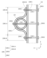
- a cross-sectional view taken along line IIIb-IIIb' showing an overview of the fixing portion of the main shaft and the opening edge support structure.
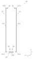
- FIG. 2 is a side view showing an outline of a main shaft.
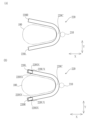
- 1A is a plan view showing an outline of an opening edge support structure
- FIG. 1B is a bottom view showing an outline of the opening edge support structure.
- FIG. 6A is a cross-sectional view taken along line VIa-VIa' showing an outline of the stand shaft rotating mechanism
- FIG. 6B is an exploded view showing an outline of the stand shaft rotating mechanism
- FIG. 6C is a cross-sectional view taken along line VIc-VIc' showing an outline of the stand shaft rotating mechanism
- 1A is an exploded view showing an outline of the stand shaft rotating mechanism
- FIG. 1B is a front view showing an outline of the retaining ring
- 1A is a plan view showing an outline of the support bottom plate
- FIG. 1B is a side view showing an outline of the support bottom plate, the stand shaft rotating mechanism, and the connecting mechanism.
- FIG. 2 is a side view showing an overview of the stand shaft.
- FIG. 2 is an exploded perspective view showing an overview of a stand shaft rotating mechanism.
- FIG. 4 is an exploded view showing an overview of a connecting mechanism.
- FIG. 4 is a partial enlarged view showing an outline of a connecting mechanism.
- A) is a cross-sectional view taken along line XIIa-XIIa' showing an overview of the coupling mechanism.
- B) is a plan view showing an overview of the coupling mechanism.
- (C) is a plan view showing an overview of the coupling mechanism.
- FIG. 2 is a side view showing an overview of the frame (open state).
- 1A is a plan view showing an outline of a support bottom plate rotating mechanism (modification)
- FIG. 1B is a side view showing an outline of the support bottom plate rotating mechanism (modification)
- 1A is a plan view showing an outline of a rotating holding plate (modified example)
- FIG. 1B is a side view showing an outline of the rotating holding plate (modified example).
- any horizontal direction will be referred to as the X direction
- the horizontal direction perpendicular to the X direction will be referred to as the Y direction
- the direction perpendicular to the X and Y directions will be referred to as the Z direction.
- the golf bag 2 comprises a bag body 100 capable of housing golf clubs, and a frame 200 to which the bag body 100 can be attached.
- the bag body 100 is formed in a long shape and is used with the opening facing upward when in use. When in use, the storage space of the bag body 100 extends in the height direction (Z direction in the figure).
- the frame 200 includes a main shaft 210 arranged along the depth direction of the storage space of the bag body 100 (Z direction in the figure), an opening edge support structure 220 arranged at the upper end of the main shaft 210, a support bottom plate 230 for supporting the bottom 100B of the bag body 100, a pair of stand shafts 240 extending from the opening edge support structure 220, a support bottom plate rotation mechanism 250 connecting the support bottom plate 230 and the main shaft 210, a stand shaft rotation mechanism 260 connecting the opening edge support structure 220 and the stand shaft 240, a connection mechanism 270 connecting the support bottom plate 230 and the stand shaft 240, and a handle 280.
- the main shaft 210 extends linearly in the Z direction along the bag body 100 from near the opening edge 100T to the bottom 100B of the bag body 100.
- a main shaft lower end hole 210UX is formed in the lower end 210U of the main shaft 210.
- the lower end 210U of the main shaft 210 is preferably flat.
- the lower end 210U is preferably parallel to the XZ plane.
- the main shaft 210 is required to be lightweight and strong. For this reason, a pipe (cylinder or square tube) made of metal (for example, aluminum alloy or stainless steel) is often used for the main shaft 210.
- the opening edge support structure 220 is disposed along the opening edge 100T of the bag body 100.
- the opening edge support structure 220 is formed in a U-shape in a plan view.
- the upper end of the main shaft 210 is connected to the center portion 220C of the opening edge support structure 220 by a fixing bracket 220K.
- the fixing bracket 220K includes a fixing bracket plate 220KA, a bolt 220KB, and a nut 220KC that can be screwed onto the bolt 220KB.
- the fixing metal plate 220KA is formed in a plate shape and is arranged along the main shaft 210.
- the fixing metal plate 220KA includes a curved portion 220KAA formed in a semicircular arc shape in a side view, a plate-shaped extension plate portion 220KAB extending from one end of the curved portion 220KAA, and a plate-shaped extension plate portion 220KAC extending from the other end of the curved portion 220KAA.
- An insertion hole 220KX for the bolt 220KB is formed in each of the curved portion 220KAA and the extension plate portions 220KAB to 220KAC.
- an insertion hole 220KX for the bolt 220KB is formed in the center portion 220 of the opening edge support structure 220.
- Three insertion holes 220KX for the bolt 220KB are also formed at the upper end of the main shaft 210 so as to be aligned at a predetermined interval.
- the main shaft 210 and the fixing bracket plate 220KA are positioned so that the insertion holes 220KX at the upper and lower ends of the main shaft 210 overlap with the insertion holes 220KX of the extension plate portion 220KAB.
- the bolts 220KB and nuts 220KC are temporarily tightened, and the opening edge support structure 220 is passed through the gap between the curved portion 220KAA and the main shaft 210.
- the main shaft 210 and the fixing bracket 220K are fixed with the bolts 220KB and nuts 220KC.
- the opening edge support structure 220 is sandwiched between the main shaft 210 and the fixing bracket 220K.
- the three pairs of bolts 220KB and nuts 220KC are fully tightened.
- the lower portions of the left end 220L and the right end 220R of the opening edge support structure 220 are provided with stand shaft insertion holes 220UX into which the upper end of the stand shaft 240 can be inserted.
- a pair of side holes 220SX are formed in the side portion of the left end 220L of the opening edge support structure 220.
- a pair of side holes 220SX are formed in the side portion of the right end 220R of the opening edge support structure 220.
- both ends (the left end 220L and the right end 220R) of the opening edge support structure 220 are spaced apart from each other, and the distance therebetween is preferably large enough to allow the bag body 100 to pass through.
- the opening edge support structure 220 is required to be lightweight and strong. For this reason, metal (e.g., aluminum alloy or stainless steel) pipes (cylinders or square tubes) are often used for the opening edge support structure 220.
- the support bottom plate 230 is formed in a plate shape, and one end 230A of the support bottom plate 230 is connected to the lower end of the main shaft 210 by a support bottom plate rotation mechanism 250.
- the other end 230B of the support bottom plate 230 is connected to the stand shaft 240 by a connection mechanism 270 ( Figure 1).
- the support bottom plate 230 is required to be lightweight. For this reason, a plate member made of metal (e.g. aluminum alloy or stainless steel) or synthetic resin is often used for the support bottom plate 230.
- the pair of stand shafts 240 function as a tripod together with the main shaft 210.
- Each of the pair of stand shafts 240 extends linearly.
- the upper ends 240T of the pair of stand shafts 240 are inserted into the stand shaft insertion holes 220UX. Furthermore, the upper ends 240T of the pair of stand shafts 240 are formed with stand shaft upper end holes 240TX. The upper ends of the stand shafts 240 are connected to the opening edge support structure 220 by the stand shaft rotation mechanism 260.
- a mid-portion insertion hole 240CX is formed in the mid-portion of each pair of stand shafts 240.
- Rubber feet 240UG are provided at the lower ends of each pair of stand shafts 240.
- the support base plate rotation mechanism 250 includes a bolt 251 that can be inserted into the main shaft lower end hole 210UX, a nut 252 that can be screwed into the bolt 251, a screw 253 that can be screwed into a screw hole NX formed in the support base plate 230, and a pair of L-shaped metal fittings 254 in which a screw insertion hole 253X and a bolt insertion hole 251X are formed.
- Both the left and right L-shaped brackets 254 and the support bottom plate 230 are fixed using screws 253.
- the bolt 251 is passed through the bolt insertion hole 251X of one L-shaped bracket 254, the main shaft lower end hole 210UX, and the bolt insertion hole 251X of the other L-shaped bracket 254, in that order.
- the bolt 251 is arranged to extend in the Y direction.
- the nut 252 is screwed onto the bolt 251.
- one end 230A of the support bottom plate 230 is connected to the lower end of the main shaft 210, and the other end 230B of the support bottom plate 230 is free to rotate around the bolt 251 as a rotation axis ( Figure 7 (B)).
- the stand shaft rotation mechanism 260 includes a bolt 261 that can be inserted into the side hole 220SX and the stand shaft upper end hole 240TX of the opening edge support structure 220, and a nut 262 that can be screwed into the bolt 261.
- the bolt 261 is passed through the side hole 220SX and the stand shaft upper end hole 240TX. At this time, the bolt 261 is arranged so that it extends in the Y direction.
- the nut 262 is then screwed into the bolt 261.
- the upper end of the stand shaft 240 is connected to the opening edge support structure 220, and the lower end of the stand shaft 240 is freely rotatable around the bolt 261 as a rotation axis ( Figure 6A(C)).
- a shaft member 361 may be used instead of the bolt 261, and a retaining ring (E-ring, etc.) 362 may be used instead of the nut 262.
- the retaining ring 362 is formed in a plate shape and includes an elastic deformation portion 362A formed in an arc shape and an engagement protrusion 362B provided on the inside of the elastic deformation portion 362A.
- the engagement protrusion 362B extends toward the center of the elastic deformation portion 362A and is capable of engaging with an engagement groove 361K formed in the shaft member 361.
- Three engagement protrusions 362B are arranged at a predetermined interval in the circumferential direction in the elastic deformation portion 362A.
- the engagement protrusions 362B are provided at both ends and a middle portion of the elastic deformation portion 362A.
- the engagement protrusions 362B provided at both ends of the elastic deformation portion 362A can be freely switched between a widened state in which the insertion of the shaft member 361 is permitted and a narrowed state in which the insertion of the shaft member 361 is restricted (FIG. 6B (B)) by the deformation of the elastic deformation portion 362A. It is preferable that the engagement protrusions 362B are biased to the narrowed state.
- the connecting mechanism 270 includes a pair of connecting shafts 271 extending in a straight line, a stopper 272 that can be attached and detached to the connecting shafts 271 (upper L-shaped structure 271TL described below), a rotating retaining plate 275 disposed on the support base plate 230, and a screw 276 that can be screwed into a screw hole NX formed in the support base plate 230.
- the connecting shaft 271 includes a straight connecting shaft portion 271S that extends in a straight line, a lower L-shaped structure 271UL provided at the lower end of the connecting shaft 271, and an upper L-shaped structure 271TL provided at the upper end of the connecting shaft 271.
- the rotating retaining plate 275 has a main body 275B formed in a plate shape, and a screw hole 275NX into which a screw 276 can be inserted is formed on one end side of the main body 275B.
- the L-shaped structure retaining hole 275LX is formed to extend in the Y direction when the rotating retaining plate 275 is in a horizontal state.
- the tip of the lower L-shaped structure 271UL of the connecting shaft 271 is engaged with the L-shaped structure retaining hole 275LX. At this time, the tip of the lower L-shaped structure 271UL extends in the Y direction.
- the connecting shaft 271 and the support bottom plate 230 are connected so as to be rotatable around the tip of the lower L-shaped structure 271UL as the rotation axis ( Figure 7(B)).
- the upper L-shaped structure 271TL at the upper end of the connecting shaft 271 is inserted into the mid-hole 240CX of the stand shaft 240, and then the stopper 272 is fixed to the tip of the upper L-shaped structure 271TL. At this time, the tip of the upper L-shaped structure 271TL extends in the Y direction.
- the connecting shaft 271 and the stand shaft 240 are connected so as to be freely rotatable with the tip of the upper L-shaped structure 271TL as the rotation axis (FIG. 13).
- the handle 280 extends from the upper end of the main shaft 210.
- the base end of the handle 280 extends straight from the upper end of the main shaft 210, and the middle part of the handle 280 is curved and folded back.
- the tip end of the handle 280 extends straight from the middle part.
- the handle 280 as a whole has a hiragana 'S' shape (when viewed from the side).
- the handle 280 may be connected to the upper end of the main shaft 210.
- the bag body 100 comprises an attachment belt 110 provided on the opening edge 100T, and a through tube 120 provided at a predetermined interval from the vicinity of the opening edge 100T to the bottom 100B of the bag body 100.
- the attachment belt 110 is provided at a predetermined interval on the opening edge 100T, and comprises a male belt piece with a male hook and a female belt piece with a female hook.
- the male hook is freely attached and detached to the female hook.
- a loop is made with the male belt piece and the female belt piece hook. After passing the opening edge support structure 220 through the loop, the male hook is fastened to the female hook, and the attachment belt 110 is engaged with the opening edge support structure 220.
- the attachment belt 110 is in a retracted state from the engaged state with respect to the opening edge support structure 220 (engaged and retracted state).
- the opening edge 100T can be detachably attached to the opening edge support structure 220 using the male belt piece and the female belt piece.
- the through tube 120 has a dimension that allows the main shaft 210 to be inserted therethrough, and extends in the Z direction.
- the movement of the bag body 100 in the Z direction along the main shaft 210 is restricted, whereas when the mounting belt 110 is engaged and retracted, the movement of the bag body 100 in the Z direction along the main shaft 210 is permitted.
- the movement of the bag body 100 along the main shaft 210 allows the through tube 120 to be freely engaged and disengaged from the main shaft 210.
- the bag body 100 may have a bag body connecting piece 130 provided on the bottom 100B.
- the bag body connecting piece 130 is provided in front of the bottom 100B of the bag body 100 (on the left side in FIG. 14). It is preferable that the bag body connecting piece 130 is provided on the opposite side in the X direction from the position where the through tube 120 is provided.
- the bag body connecting piece 130 is formed in a belt shape, and a screw insertion hole into which a screw 276 (FIG. 10) can be inserted is formed at the tip.
- the screw 276 can be inserted into the screw insertion hole of the bag body connecting piece 130 when fixing the rotating holding plate 275 to the supporting bottom plate 230 using the screw 276.
- the frame 200 (Fig. 1) is placed in an upright position.
- the bolt 251 and nut 252 in the support base plate pivot mechanism 250 are removed (Fig. 9).
- the lower end 210U of the main shaft 210 is passed through the through tube 120 (Fig. 14) at the top of the bag body 100 to the through tube 120 at the bottom in order.
- the opening edge 100T is attached to the opening edge support structure 220 using the mounting belt 110.
- the bolt 251 is passed through the bolt insertion hole 251X of one L-shaped metal fitting 254, the main shaft lower end hole 210UX, and the bolt insertion hole 251X of the other L-shaped metal fitting 254 in that order.
- the nut 252 is screwed onto the bolt 251.
- one end 230A of the support base plate 230 is connected to the lower end of the main shaft 210, and the other end 230B of the support base plate 230 is freely rotatable around the bolt 251 as a rotation axis.
- the support bottom plate 230 rotates around the bolt 251.
- the connecting shaft 271 rotates around the tip of the lower L-shaped structure 271UL relative to the support bottom plate 230, while rotating around the tip of the upper L-shaped structure 271TL relative to the stand shaft 240.
- the stand shaft 240 rotates around the bolt 261 and moves away from the main shaft 210, becoming an open state. This allows the main shaft 210 and the pair of stand shafts 240 to function as a tripod.
- the support base plate 230 rotates around the bolt 251.
- the connecting shaft 271 rotates around the tip of the lower L-shaped structure 271UL relative to the support base plate 230, while rotating around the tip of the upper L-shaped structure 271TL relative to the stand shaft 240.
- the stand shaft 240 rotates around the bolt 261, approaching the main shaft 210 and entering a closed state.
- the golf bag 2 can open and close the tripod (the main shaft 210 and the pair of stand shafts 240) by switching between a state in which the main shaft 210 is tilted diagonally relative to the support base plate 230 ( Figure 13) and a state in which it is upright vertically ( Figure 1).
- the bag body 100 can be attached to and detached from the frame 200 by simply attaching and detaching the bolts 251 and nuts 252, making it possible to attach bags of a wide variety of designs. Furthermore, since both ends of the opening edge support structure 220 (the left end 220L and the right end 220R) are separated from each other, bag bodies 100 with various opening shapes can be attached to the frame 200.
- the structure is simple while maintaining high strength.
- the opening width in the Y direction of the stand shaft insertion hole 220UX abuts the opening edge of the stand shaft insertion hole 220UX with the stand shaft 240 at the upper and lower limits of the opening angle, i.e., at the upper limit of the specified closed state and the specified open state ( Figure 6 (C)).
- the rotation angle of the stand shaft 240 is not limited to being regulated by the opening width of the stand shaft insertion hole 220UX in the Y direction, but may be regulated by the rotation angle between the support base plate 230 and the main shaft 210, or by the rotation angle between the connecting shaft 271 and the stand shaft 240.
- the frame 200 may be provided with a handle 291.
- the handle 291 includes a band 291A extending from one stand shaft 240 to the other stand shaft 240, and a grip 291B connected to the band 291A.
- the upper end of the grip 291B is connected to the upper end of the main shaft 210.
- the lower end of the grip 291B is connected to the middle of the band 291A.
- the bag body 100 and the frame 200 are positioned lower than the grip portion 291B due to their own weight, and tension is applied to the belt portion 291A in the direction of the grip portion 291B.
- the stand shaft 240 is in a closed state.
- a pair of stand shafts 240 are connected by a band portion 291A, and the middle portion of the band portion 291A and the upper end portion of the main shaft 210 are connected by a grip portion 291B, but the present disclosure is not limited to this, and it is sufficient that the connection position between the grip portion 291B and the main shaft 210 is higher than the connection position between the band portion 291A and the stand shaft 240.
- the frame 200 may include a shoulder belt 295.
- the shoulder belt 295 extends from the upper end of the main shaft 210 to the lower end of the main shaft 210. It is preferable that the shoulder belt 295 passes between the belt portion 291A and the main shaft 210.
- the main shaft 210 and the opening edge support structure 220 are made of pipes (cylinders or square tubes), but the present disclosure is not limited to this and may be elliptical, triangular, hexagonal, etc.
- the stand shaft 240 and the connecting shaft 271 may also be made of pipes (cylinders or square tubes).
- the opening edge support structure 220 is U-shaped in plan view, but the present disclosure is not limited to this and may be V-shaped or C-shaped in plan view.
- the attachment belt 110 is used as the attachment/detachment structure, but the present disclosure is not limited to this.
- an engagement structure that can engage with the opening edge support structure 220 may be used.
- the engagement structure may include a ring provided on the bag body 100 and a protrusion provided on the opening edge support structure 220 that can engage with the ring.
- the connecting mechanism 270 uses a pair of connecting shafts 271 extending linearly.
- a connecting shaft in which the pair of connecting shafts 271 are integrated may be used.
- the support base plate rotation mechanism 250 is used, but the present disclosure is not limited to this.
- a support base plate rotation mechanism 350 may be used.
- the support base plate rotation mechanism 350 includes an axis member 361 that can be inserted into the main shaft lower end hole 210UX, a retaining ring 362, a screw 353 that can be screwed into a screw hole (not shown) formed in the support base plate 230, and a retaining metal fitting 354.
- the fastening fitting 354 is disposed on the support base plate 230 and comprises a plate-shaped mounting plate portion 354A extending in the X direction, and protruding plate portions 354B protruding upward from both ends of the mounting plate portion 354A in the width direction (Y direction in the figure).
- a screw insertion hole is formed in the mounting plate portion 354A.
- the two protruding plate portions 354B are formed with rod member insertion holes 354X into which the shaft member 351 can be inserted.
- the fastener 354 is placed on the support bottom plate 230 so that the screw insertion hole of the fastener 354 faces the screw hole formed in the support bottom plate 230. Then, the support bottom plate 230 and the fastener 354 are fixed using the screw 353. Next, the main shaft 210 is aligned with the fastener 354 so that the main shaft lower end hole 210UX faces the rod member insertion hole 354X. Then, the main shaft 210 is connected to the fastener 354 using the shaft member 351 and the retaining ring 352. The main shaft 210 is now in a state where it can rotate freely around the shaft member 351.
- bolts and nuts are used to connect the various components, but the present disclosure is not limited to this.
- a shaft member with a locking groove and a retaining ring (such as an E-ring) that can engage with the locking groove may also be used.
- a rotating holding plate 375 may be used instead of the rotating holding plate 275.
- the rotating holding plate 375 includes a lower holding plate 375A arranged on the support bottom plate 230 and an upper holding plate 375B that is placed on the lower holding plate 375A.
- the upper holding plate 375B includes a flat plate portion and a curved portion that is curved so as to be convex upward.
- the lower holding plate 375A is formed with a screw hole 375AX into which the screw 276 can be inserted
- the flat plate portion of the upper holding plate 375B is formed with a screw hole into which the screw 276 can be inserted.
- the lower holding plate 375A is placed on the support bottom plate 230, and the upper holding plate 375B is placed on top of it. Screws 276 are inserted into both screw holes to temporarily fasten the lower holding plate 375A and the upper holding plate 375B on the support bottom plate 230. After that, the connecting shaft 271 is inserted into the insertion hole 375X, and then the screws 276 are used for final fastening to connect the lower holding plate 375A and the upper holding plate 375B to the support bottom plate 230. When fixing the rotating holding plate 375 to the support bottom plate 230 using the screws 276, the screws 276 may be inserted into the screw insertion holes of the bag body connecting pieces 130 and then temporarily fastened.
Landscapes
- Health & Medical Sciences (AREA)
- General Health & Medical Sciences (AREA)
- Physical Education & Sports Medicine (AREA)
- Purses, Travelling Bags, Baskets, Or Suitcases (AREA)
Priority Applications (1)
| Application Number | Priority Date | Filing Date | Title |
|---|---|---|---|
| JP2024554319A JPWO2024095654A1 (https=) | 2022-11-04 | 2023-09-29 |
Applications Claiming Priority (2)
| Application Number | Priority Date | Filing Date | Title |
|---|---|---|---|
| JP2022-177487 | 2022-11-04 | ||
| JP2022177487 | 2022-11-04 |
Publications (1)
| Publication Number | Publication Date |
|---|---|
| WO2024095654A1 true WO2024095654A1 (ja) | 2024-05-10 |
Family
ID=90930374
Family Applications (1)
| Application Number | Title | Priority Date | Filing Date |
|---|---|---|---|
| PCT/JP2023/035808 Ceased WO2024095654A1 (ja) | 2022-11-04 | 2023-09-29 | フレーム及びゴルフバック |
Country Status (2)
| Country | Link |
|---|---|
| JP (1) | JPWO2024095654A1 (https=) |
| WO (1) | WO2024095654A1 (https=) |
Citations (4)
| Publication number | Priority date | Publication date | Assignee | Title |
|---|---|---|---|---|
| US4778136A (en) * | 1987-02-12 | 1988-10-18 | Reimers Eric W | Golf bag with integral stand |
| JP2001079127A (ja) * | 1999-08-26 | 2001-03-27 | Karsten Mfg Corp | カム作動サポートスタンドと分離可能なバッグ本体とを備えたゴルフバッグ |
| US6652045B1 (en) * | 2000-03-05 | 2003-11-25 | Ms-Trade Gmbh & Co. | Support device for a golf bag |
| JP2009131586A (ja) * | 2007-08-31 | 2009-06-18 | Karsten Manufacturing Corp | 円弧状支持部材を有するゴルフバッグ |
-
2023
- 2023-09-29 JP JP2024554319A patent/JPWO2024095654A1/ja active Pending
- 2023-09-29 WO PCT/JP2023/035808 patent/WO2024095654A1/ja not_active Ceased
Patent Citations (4)
| Publication number | Priority date | Publication date | Assignee | Title |
|---|---|---|---|---|
| US4778136A (en) * | 1987-02-12 | 1988-10-18 | Reimers Eric W | Golf bag with integral stand |
| JP2001079127A (ja) * | 1999-08-26 | 2001-03-27 | Karsten Mfg Corp | カム作動サポートスタンドと分離可能なバッグ本体とを備えたゴルフバッグ |
| US6652045B1 (en) * | 2000-03-05 | 2003-11-25 | Ms-Trade Gmbh & Co. | Support device for a golf bag |
| JP2009131586A (ja) * | 2007-08-31 | 2009-06-18 | Karsten Manufacturing Corp | 円弧状支持部材を有するゴルフバッグ |
Also Published As
| Publication number | Publication date |
|---|---|
| JPWO2024095654A1 (https=) | 2024-05-10 |
Similar Documents
| Publication | Publication Date | Title |
|---|---|---|
| US8387217B1 (en) | Strap attachment device | |
| CN102448554B (zh) | 具有双带到单带可转换的高尔夫球袋 | |
| CN203241686U (zh) | 照相机安装设备 | |
| CN101952162B (zh) | 连接件、支架和支撑组件的改进 | |
| US5358109A (en) | Golf bag | |
| US5356003A (en) | Golf bag with stand | |
| US7905667B2 (en) | Compactible walking staff having tripod base and adaptable mount | |
| JP4308143B2 (ja) | 単肩両肩支持切換を行う携行品のための運搬具 | |
| US20100025444A1 (en) | Hands-Free Viewing Assemblies for Portable Media Players | |
| CA3041481A1 (fr) | Attachment device for quick connect of trekking, shooting and weight assist equipment | |
| US20120231896A1 (en) | Adjustable golf club shaft and hosel assembly | |
| US20020125667A1 (en) | Golf cart | |
| US6805640B2 (en) | Golf swing training aid | |
| US6758334B2 (en) | Golf bag | |
| US9044652B2 (en) | Adjustable golf club shaft and hosel assembly | |
| US7124887B2 (en) | Extension handle and golf bag with extension handle | |
| JPH08508953A (ja) | 固定装置 | |
| WO2011003114A2 (en) | Television safety strap | |
| US20200064106A1 (en) | Modular, Collapsible, and Portable Ballistic Shield System | |
| KR100273666B1 (ko) | 운반장치가 구비된 골프백 | |
| US4054256A (en) | Support for a golf bag | |
| WO2024095654A1 (ja) | フレーム及びゴルフバック | |
| JP2000051417A (ja) | ゴルフバッグ運搬装置 | |
| US10023213B1 (en) | Disc golf transport system | |
| US20050137036A1 (en) | Portable fence-mountable basketball goal and method |
Legal Events
| Date | Code | Title | Description |
|---|---|---|---|
| 121 | Ep: the epo has been informed by wipo that ep was designated in this application |
Ref document number: 23885417 Country of ref document: EP Kind code of ref document: A1 |
|
| WWE | Wipo information: entry into national phase |
Ref document number: 2024554319 Country of ref document: JP |
|
| NENP | Non-entry into the national phase |
Ref country code: DE |
|
| 122 | Ep: pct application non-entry in european phase |
Ref document number: 23885417 Country of ref document: EP Kind code of ref document: A1 |