WO2024095631A1 - 管路内作業装置 - Google Patents
管路内作業装置 Download PDFInfo
- Publication number
- WO2024095631A1 WO2024095631A1 PCT/JP2023/034361 JP2023034361W WO2024095631A1 WO 2024095631 A1 WO2024095631 A1 WO 2024095631A1 JP 2023034361 W JP2023034361 W JP 2023034361W WO 2024095631 A1 WO2024095631 A1 WO 2024095631A1
- Authority
- WO
- WIPO (PCT)
- Prior art keywords
- legs
- robot
- leg
- working device
- pipe
- Prior art date
- Legal status (The legal status is an assumption and is not a legal conclusion. Google has not performed a legal analysis and makes no representation as to the accuracy of the status listed.)
- Ceased
Links
Images


Classifications
-
- B—PERFORMING OPERATIONS; TRANSPORTING
- B25—HAND TOOLS; PORTABLE POWER-DRIVEN TOOLS; MANIPULATORS
- B25J—MANIPULATORS; CHAMBERS PROVIDED WITH MANIPULATION DEVICES
- B25J5/00—Manipulators mounted on wheels or on carriages
-
- G—PHYSICS
- G01—MEASURING; TESTING
- G01N—INVESTIGATING OR ANALYSING MATERIALS BY DETERMINING THEIR CHEMICAL OR PHYSICAL PROPERTIES
- G01N21/00—Investigating or analysing materials by the use of optical means, i.e. using sub-millimetre waves, infrared, visible or ultraviolet light
- G01N21/84—Systems specially adapted for particular applications
- G01N21/88—Investigating the presence of flaws or contamination
- G01N21/95—Investigating the presence of flaws or contamination characterised by the material or shape of the object to be examined
- G01N21/954—Inspecting the inner surface of hollow bodies, e.g. bores
Definitions
- the present invention relates to an in-pipe work device that can perform various tasks such as inspection (photography) and measurement while moving inside a pipe such as a sewer pipe.
- Patent Document 1 discloses a self-propelled pipe inspection camera device that includes a pipe diameter conversion unit that is compatible with a variety of pipe diameters and that constitutes a traveling unit that has a camera mounting unit and that self-propels along the piping direction within the pipe to be inspected by remote control, and an imaging camera mounted on the camera mounting unit.
- Patent Document 2 discloses a pipeline inner diameter inspection device that is provided with two sled-like sliding members on the bottom of a carriage, thereby enabling the device to travel within a pipeline in the pipeline's length direction.
- Patent Document 1 in a traveling unit having a plurality of wheels (tires), some of the wheels may slip on the debris or get caught on the debris or obstacle, causing the unit to be unable to travel, resulting in a problem of lack of stability in travel. Also, as in Patent Document 2, in the case of a cart equipped with a sled-like sliding member, the tip of the sliding member is likely to get caught on the debris or obstacle, causing the unit to be unable to travel, resulting in a problem of lack of stability in travel.
- Patent Document 2 a traction line such as a wire is attached to both ends of the base of the cart in the length direction of the pipeline, and the cart is moved back and forth by pulling this traction line. Therefore, it is necessary to pass the traction line from one end of the pipeline to the other in advance, but it is difficult to pass the traction line in a pipeline with a small diameter, resulting in a problem of lack of practicality.
- the present invention has been made in consideration of the above circumstances, and aims to provide an in-pipe working device with excellent mobility that is less susceptible to the influence of various deposits and obstacles present inside the pipeline and can move reliably inside the pipeline.
- the in-pipe working device of the present invention which is in line with the above-mentioned objectives, comprises a multi-legged walking work robot equipped with an imaging means for photographing the inside of the pipeline being the subject of work, and a controller connected by wire to the work robot, and the work robot is operated from outside the pipeline by the controller to move inside the pipeline.
- the structure of the walking means (legs) of the multi-legged walking work robot is appropriately selected from those conventionally known, and it is sufficient that it has at least four legs, but the number of legs may be six or eight, or may be ten or more.
- the legs are arranged symmetrically on the left and right, and the arrangement interval of the legs in the front-back direction (longitudinal direction) of the work robot is appropriately selected.
- the structure may be such that each leg walks independently (forward and backward movement), or a plurality of legs are linked by a link mechanism to walk continuously (with a time lag) (forward and backward movement).
- the actuator for driving the legs may be a piston cylinder, or a motor.
- the work robot and the controller are wired to each other by a connection cable including a communication line and/or a power line.
- the working robot preferably comprises a robot body and a walking means attached to the robot body, the walking means preferably having left and right inner legs arranged on both sides of the robot body, left and right outer legs arranged outside the inner legs, and a drive unit mounted on the robot body for driving the inner legs and the outer legs.
- each of the outer legs can be made adjustable in length.
- each of the outer legs is adjusted by abutments that are removably attached to the tip of each outer leg.
- each of the outer legs may be rotatable in the circumferential direction of the pipeline.
- each of the inner legs and each of the outer legs have a Theo-Janssen mechanism, and the drive unit is equipped with a single motor that moves each of the inner legs and each of the outer legs back and forth in conjunction with each other.
- the left and right inner legs are arranged symmetrically, each having an inner front leg and an inner rear leg
- the left and right outer legs are arranged symmetrically, each having an outer front leg and an outer rear leg, and when the working robot moves, each of the inner front legs, each of the inner rear legs, each of the outer front legs, and each of the outer rear legs move back and forth in conjunction with the rotation of the motor.
- the device has a display connected to or mounted on the controller, and an image of the inside of the pipeline captured by the imaging means is displayed on the display in real time.
- the in-pipe working device further comprises one or more auxiliary work robots which are connected by wire to the work robot and move inside the pipeline together with the work robot.
- the wired connection between the work robot and the auxiliary work robot uses a connection cable including a communication line and/or a power line, similar to the wired connection between the controller and the work robot.
- adjacent housings of the work robot and the one or more auxiliary work robots arranged in series are selectively connected to each other by a connector.
- the one or more auxiliary work robots are equipped with the same walking means as the work robot.
- the in-pipe work device of the present invention comprises a multi-legged walking work robot equipped with an imaging means for photographing the inside of the pipe being worked on, and a controller connected by wire to the work robot.
- the work robot is operated from outside the pipe by the controller to move inside the pipe, so that even inside a pipe with a diameter that is too large for a person to enter (for example, an inner diameter of about 200 to 300 mm), the work robot can be reliably moved by instructions from the controller to perform various tasks.
- the working robot when the working robot comprises a robot body and a walking means attached to the robot body, and the walking means has left and right inner legs arranged on both sides of the robot body, left and right outer legs arranged on the outside of each inner leg, and a drive unit mounted on the robot body for driving each inner leg and each outer leg, the working robot can walk using at least four legs driven by the drive unit.
- each outer leg is adjustable, the length of each outer leg can be adjusted according to the inner diameter of the pipeline, allowing the working robot to move with each inner leg and each outer leg securely in contact with the inner surface of the pipeline, providing excellent versatility.
- the working robot when the length of each outer leg is adjusted by abutments that are removably attached to the tip of each outer leg, the working robot can handle pipelines with different inner diameters simply by replacing the abutments, simplifying the mechanism.
- each outer leg can rotate in the circumferential direction of the pipeline
- the working robot can rotate (move) each outer leg in the circumferential direction of the pipeline according to the inner diameter of the pipeline, and move with each inner leg and each outer leg securely in contact with the inner surface of the pipeline, providing excellent versatility.
- each inner leg and each outer leg has a Theo Jansen mechanism and the drive unit is equipped with a single motor that moves each inner leg and each outer leg back and forth in conjunction with each other
- the rotation of the single motor can be converted into back and forth motion of each leg with a simple structure, allowing each inner leg and each outer leg to be smoothly linked with each other, resulting in excellent stability in the walking movement of the working robot.
- the inner leg and the outer leg move back and forth with different timing while touching the ground, so that the robot body is reliably supported when the working robot moves, and stable walking is achieved.
- the left and right inner legs are arranged symmetrically, each having an inner front leg and an inner hind leg
- the left and right outer legs are arranged symmetrically, each having an outer front leg and an outer hind leg, and when the working robot moves, each inner front leg, each inner hind leg, each outer front leg, and each outer hind leg move back and forth in conjunction with the rotation of the motor, the working robot can walk stably using eight legs.
- the in-pipe working device when a display is connected to or mounted on the controller and an image of the inside of the pipe captured by the imaging means is displayed on the display in real time, the user can operate the controller while visually checking the image of the inside of the pipe displayed on the display to smoothly move the work robot, providing excellent operability.
- the in-pipe work device when there is one or more auxiliary work robots that are wired to the work robot and move inside the pipeline together with the work robot, even if the travel distance is long, there is no need for the work robot to drag a long connection cable alone, and the length of each connection cable that sequentially connects the work robot, one or more auxiliary work robots, and the controller is shortened, significantly reducing the load that the work robot and auxiliary work robot receive from the connection cables, achieving smoother movement.
- the adjacent housings of the work robot and one or more auxiliary work robots arranged in series are selectively connected by a connector, depending on the material and physical properties (rigidity, flexibility or suppleness) or mechanism (mobility) of the connector, it is possible to improve transportability and straight-line movement, or improve the ability to navigate around curves (prevent tipping over), thereby expanding the functionality and uses.
- auxiliary work robots are equipped with the same walking means as the work robot, the worker can easily operate the work robot and one or more auxiliary work robots by coordinating their walking movements with each other using only one controller.
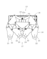
- FIG. 1 is a perspective view showing an in-pipe processing device according to a first embodiment of the present invention
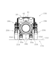
- FIG. 2 is a front view showing a working robot of the in-pipe working device.
- 4A and 4B are front views of the main part showing a drive mechanism of a working robot of the intra-pipe working device.
- FIG. 2 is a first side view showing the walking motion of the working robot of the in-pipe working device.
- FIG. 11 is a second side view showing the walking motion of the working robot of the intra-pipe working device.
- FIG. 11 is a third side view showing the walking motion of the working robot of the intra-pipe working device.
- FIG. 11 is a fourth side view showing the walking motion of the working robot of the intra-pipe working device.
- FIG. 13 is a front view showing the in-pipe working device in a used state with outer legs of the working robot spread outward.
- FIG. FIG. 2 is a side view showing the inside-pipe processing device in use.
- FIG. 11 is a plan view showing a first usage state of a working robot of an in-pipe processing apparatus according to a second embodiment of the present invention.
- FIG. 2 is a side view showing a first usage state of the working robot of the intra-pipe working apparatus.
- FIG. 2 is a front view showing a first usage state of the working robot of the intra-pipe working device.
- FIG. 11 is a front view showing a second usage state of the work robot of the intra-pipe working device.
- FIG. 11 is a front view showing a third usage state of the work robot of the intra-pipe working device.
- FIG. 11 is a fourth usage state of the work robot of the intra-pipe working device.
- FIG. 1 An in-pipe operation device 10 according to a first embodiment of the present invention shown in FIG. 1 is used for various operations such as inspection (photography) and measurement inside a pipe 11 (FIG. 2) such as a sewer pipe.
- the in-pipe work device 10 has a multi-legged walking work robot 13 equipped with an imaging means 12 that takes images of the inside of the pipeline 11, and a controller 15 connected to the work robot 13 via a connection cable 14 including a communication line and a power line, and the work robot 13 is operated from outside the pipeline 11 by the controller 15 to move inside the pipeline 11.
- the working robot 13 comprises a robot body 16 and walking means 17 attached to the robot body 16.
- the walking means 17 comprises left and right inner legs 18 disposed on both sides of the robot body 16, left and right outer legs 19 disposed on the outside of each inner leg 18, and a drive unit (not shown) mounted on the robot body 16 for driving each inner leg 18 and each outer leg 19.
- the left and right inner legs 18 are disposed symmetrically and each has an inner front leg 21 and an inner hind leg 22, and the left and right outer legs 19 are disposed symmetrically and each has an outer front leg 23 and an outer hind leg 24.
- the inner leg 18 and the outer leg 19 (the inner front legs 21, the inner hind legs 22, the outer front legs 23, and the outer hind legs 24) have a Theo Jansen mechanism (an example of a link mechanism), and the drive unit is equipped with one motor (not shown) that moves the inner legs 18 and the outer legs 19 back and forth in conjunction with each other. Therefore, when the working robot 13 moves, the inner front legs 21, the inner hind legs 22, the outer front legs 23, and the outer hind legs 24 move back and forth in conjunction with the rotation of the motor.
- the drive mechanism 26 of the work robot 13 includes an inner leg drive shaft 27 for driving the left and right inner legs 18, and an outer leg drive shaft 28 for driving the left and right outer legs 19.
- the inner leg drive shaft 27 is disposed below the outer leg drive shaft 28 and parallel to the outer leg drive shaft 28, and meshing gears 27a, 28a are attached to the longitudinal center portions of the inner leg drive shaft 27 and the outer leg drive shaft 28, respectively.
- rotation input to the gear 28a from a motor (not shown) built into the work robot 13 is transmitted to the outer leg drive shaft 28 and the inner leg drive shaft 27.
- An inner leg drive disc 29 is attached to each end of the inner leg drive shaft 27, and an inner leg connecting shaft 29a is provided at a position on the inner leg drive disc 29 away from the center (inner leg drive shaft 27) on the outer peripheral side by a predetermined distance, and connected to each inner leg 18.
- the left and right inner leg drive disks 29 rotate together with the inner leg drive shaft 27, and each inner leg connecting shaft 29a makes a circular motion around the inner leg drive shaft 27 (moves along the circumference of the left and right inner leg drive disks 29), whereby the inner front legs 21 and the inner hind legs 22 of the left and right inner legs 18 are linked (interlocked) to move forward and backward. Therefore, the movements of the left and right inner legs 18 (the inner front legs 21 and the inner hind legs 22) are synchronized.
- relay gears 30a are attached to both ends of the outer leg drive shaft 28, and outer leg drive discs 32 are attached to the left and right output shafts 31, each of which has an output gear 30b that meshes with each relay gear 30a.
- An outer leg connecting shaft 32a is provided on each outer leg drive disc 32 at a position a predetermined distance away from the center (output shaft 31) on the outer leg drive disc 32 toward the outer periphery, and is connected to each outer leg 19.
- the rotation of the outer leg drive shaft 28 is transmitted to the left and right output shafts 31 via the left and right relay gears 30a and output gear 30b, and the left and right outer leg drive discs 32 rotate together with each output shaft 31, and each outer leg connecting shaft 32a moves circularly around each output shaft 31 (moving along the circumference of the left and right outer leg drive discs 32), so that the outer front legs 23 and the outer rear legs 24 of the left and right outer legs 19 are linked (interlocked) to move forward and backward. Therefore, the movements of the left and right outer legs 19 (the outer front legs 23 and the outer rear legs 24) are synchronized.
- the inner legs 18 (the inner front legs 21 and the inner hind legs 22) and the outer legs 19 (the outer front legs 23 and the outer hind legs 24) have the same structure, but differ in their mounting positions (height) relative to the robot body 16.
- the inner leg drive shaft 27 and the outer leg drive shaft 28 rotate in opposite directions, but the inner leg drive shaft 27 and the left and right output shafts 31 rotate in the same direction.
- the mounting positions of the inner leg connecting shafts 29a to the inner leg drive discs 29 and the mounting positions of the outer leg connecting shafts 32a to the outer leg drive discs 32 are shifted by 180 degrees.
- FIGS. 4 to 7 show the movement (position) of the inner front leg 21, the inner hind leg 22, the outer front leg 23, and the outer hind leg 24 when the motor rotates 90 degrees from the initial position, and from these it can be seen that there is a time difference (here, a phase difference of 180 degrees) between the movement of the inner leg 18 and the movement of the outer leg 19.
- a disk-shaped abutment 33 is rotatably supported on the tip of each of the inner front legs 21, inner hind legs 22, outer front legs 23, and outer hind legs 24 so that the contact resistance with the surface of the pipeline 11 when the working robot 13 walks can be reduced and smooth walking can be achieved, but the structure of each leg is not limited to this.
- the tip of each leg may be tapered to reduce the contact area with the surface of the pipeline 11.
- Each outer leg 19 is rotatable in the circumferential direction of the pipeline 11. Therefore, as shown in FIG. 8, by spreading each outer leg 19 outward, it is possible to accommodate a pipeline 35 having a larger pipe diameter (inner diameter) than the pipeline 11.
- a universal joint (universal joint) 36 is attached to the middle of the outer leg drive shaft 28 (two places on the left and right), so that even if each outer leg 19 is rotated in the circumferential direction of the pipeline 11, the rotation of the outer leg drive shaft 28 is transmitted to the left and right output shafts 31, and the outer front legs 23 and the outer rear legs 24 of the left and right outer legs 19 can be moved forward and backward.
- the in-pipe working device 10 can have one or more (here, four) auxiliary work robots 38 that are connected in series to the work robot 13 via a connection cable 14 and move inside the pipeline 11 together with the work robot 13.
- the auxiliary work robot 38 is a multi-legged walking robot similar to the work robot 13, and is equipped with the same walking means 17 as the work robot 13.
- the only difference between the work robot 13 and the auxiliary work robot 38 is the presence or absence of the photographing means 12, and the other structures are the same, so a description thereof will be omitted.
- the work robot 13 and each auxiliary work robot 38 are sequentially connected by the connection cable 14, and commands (control signals) from the controller 15 are transmitted to the work robot 13 and each auxiliary work robot 38.
- the movements of the work robot 13 and each auxiliary work robot 38 are linked, and they move forward or backward at the same time, so a constant distance can be maintained, and slack in the connection cable 14 can be prevented, realizing stable walking movements of the work robot 13 and each auxiliary work robot 38.
- the movements of the walking means 17 of the work robot 13 and each auxiliary work robot 38 may be synchronized (the timing is the same), or may be shifted by a predetermined time difference (phase difference).
- auxiliary work robots 38 are used for the 100m long pipeline 11, with the work robot 13 and each auxiliary work robot 38 positioned at 20m intervals, but the number of auxiliary work robots and their spacing are appropriately selected depending on the length of the pipeline and its internal conditions (presence, type and amount of deposits and obstacles, etc.). For example, there may be only one auxiliary work robot or none at all. It is also possible to equip the auxiliary work robot with a photographing means, if necessary.
- the connection cable 14 includes a power line, so that power can be supplied from a power source (not shown) installed outside the pipeline 11 (on the ground) via the connection cable 14 to drive the motors of the work robot 13 and each auxiliary work robot 38.
- the in-pipe working device 10 has a display (not shown) connected to the controller 15, and an image of the inside of the pipeline 11 photographed by the photographing means 12 is displayed on the display in real time. Therefore, a user can operate the controller 15 while visually checking the image of the inside of the pipeline 11 displayed on the display, thereby smoothly moving the work robot 13 remotely.
- the controller may be equipped with a display, in which case it does not matter whether there is a display connected to the controller or not.
- a personal computer (not shown) for collecting data may be connected to the connection cable 14 or the controller 15.
- the image data (video) captured by the image capturing means 12 can be stored in a storage means (hard disk or USB memory, etc.) built into or attached to the personal computer, and can be kept as a record of the inspection. This makes it possible to check the location of damage to the pipeline 11 by looking at the image later, and to detect damage to the pipeline 11 that could not be visually confirmed by applying image processing as necessary. It is preferable that the image displays characters indicating the inspection date and time, the inspection location, the distance traveled during the inspection, etc. The characters to be displayed on the image are input from the controller 15 or the personal computer. The distance traveled during the inspection is automatically calculated from the amount of rotation of the motor.
- the work robot and/or the auxiliary work robot are equipped with lighting (not shown).
- the worker may operate the controller 15 to retreat the work robot 13 and each auxiliary work robot 38 to the vicinity of the entrance 40 (see Figure 9) of the manhole 39 connected to the pipeline 11 and then retrieve them, or the worker may manually pull the connecting cable 14 to pull up each auxiliary work robot 38 and work robot 13 in turn from the entrance 40 and retrieve them.
- the in-pipe working device is used for various other tasks.
- various measuring devices can be mounted on the robot body of the working robot and/or the auxiliary working robot to measure the inner diameter or surface irregularities of the pipeline, measure the oxygen concentration inside the pipeline, check for the presence or absence of toxic gases, etc., and hand tools, etc. can be mounted on the robot body to remove (recover) deposits and obstacles inside the pipeline.
- the intra-pipe working device is particularly suitable for working inside small pipes that are too small for a human to enter (e.g., an inner diameter of about 200 to 300 mm), but the diameter of the pipe to be worked on is not limited and can be selected appropriately. By appropriately selecting the dimensions and shapes of the robot body, inner leg, and outer leg, it can also work with pipes with diameters of 300 mm or more.
- each outer leg 19A of the walking means 17A is configured to be adjustable in length instead of being rotatable in the circumferential direction of the pipe 11.
- the working robot 13A has abutments 33a to 33d detachably attached to the tip of each outer leg 19A, which allows the length of each outer leg 19A to be adjusted.
- each outer leg 19A of the working robot 13A is adjusted by replacing a plurality of sets (four sets in this case) of abutments 33a to 33d having different shapes (height dimensions) prepared in advance in units of sets (simultaneously for all outer legs 19A).
- the abutments 33a at the tip of each inner leg 18A are fixed (not replaced).
- the working robot 13A can travel (move) by reliably abutting the tip of each inner leg 18A (contact body 33a) and the tip of each outer leg 19A (contact body 33a-33d) not only on the pipelines 11a-11c with different inner diameters, but also on the flat ground 11d.
- the material of the abutment bodies 33a-33d is preferably synthetic rubber or synthetic resin that is non-slip and has gripping properties, but is not limited thereto, and is appropriately selected depending on the material of the pipeline or the use of the in-pipe working device.
- the materials of the abutment bodies used at the same time do not all need to be the same, and may be different between the inner leg and the outer leg, or between the front leg and the rear leg, for example.
- the imaging means 12 is attached to the robot body 16 via a height adjustment unit 41, and as shown in Figures 12 to 14, the imaging means 12 can be moved to the center position of each of the pipelines 11a to 11c, allowing the interiors of each of the pipelines 11a to 11c to be reliably photographed in detail.
- the mechanism of the inner leg 18A and the outer leg 19A (inner front leg 21A, inner hind leg 22A, outer front leg 23A, and outer hind leg 24A) constituting the walking means 17A of the working robot 13A and the mechanism of the inner leg 18 and the outer leg 19 (inner front leg 21, inner hind leg 22, outer front leg 23, and outer hind leg 24) constituting the walking means 17 of the working robot 13 are different in the shape and arrangement of each member and the number and arrangement of joints, but both are Theo Jansen mechanisms.
- the driving part of the working robot 13A also has one motor (not shown) that moves the inner leg 18A and the outer leg 19A back and forth in conjunction with each other, and when the working robot 13A moves, the inner front leg 21A, inner hind leg 22A, outer front leg 23A, and outer hind leg 24A move back and forth in conjunction with the rotation of the motor.
- the working robot 13 and the multiple auxiliary work robots 38 are connected in series via the connection cable 14, but in this embodiment, as shown in Figs. 10 and 11, the housings 42 of the adjacent working robots 13A and auxiliary work robots 38A are further connected to each other by a connector 43. If this connector 43 is made of a material having flexibility or suppleness such as synthetic rubber, even if the pipe is curved (bent), the auxiliary work robot 38A can move smoothly without falling over by following the change in the moving direction of the leading work robot 13A, improving the running ability.
- connection cable 14 connecting the working robot 13A and the auxiliary work robot 38A is protected by the connector 43 by passing through the connector 43, but the connection cable 14 may pass outside the connector 43 (arranged in parallel with the connector 43).
- the length of the connector, the shape and size (area) of the cross section perpendicular to the longitudinal direction, the number and arrangement of the connectors are not limited to this embodiment and may be selected as appropriate.
- the connector is made of a flexible or pliable material
- the material, physical properties, and mechanism (structure) of the connector are appropriately selected depending on the location or application of the in-pipe working device.
- a flexible or pliable connector such as synthetic rubber
- a connector having mobility by having a mechanism such as a joint that rotates under external force is used, the same action and effect as described above can be obtained.
- the connector is made of a rigid material such as hard synthetic resin or metal, the transportability and linearity are improved. Note that connecting the work robot and the auxiliary work robot with a rigid connector is equivalent to lengthening the overall length of the work robot and increasing the number of legs of the walking means.
- the present invention is not limited to the configurations described in the above embodiment, and also includes other embodiments and modifications that are possible within the scope of the matters described in the claims.
- the rotational motion of one motor is converted into forward and backward motion of each of the inner front legs, inner hind legs, outer front legs, and outer hind legs by the Theo Jansen mechanism, but the structure of the walking means is not limited to this and can be selected appropriately.
- the walking means of the auxiliary working robot may be different from the walking means of the working robot.
- the structure of the drive mechanism for driving the left and right inner legs and the left and right outer legs may be appropriately selected.
- the rotation of the motor may be directly transmitted (input) from a gear attached to the rotating shaft of the motor to a gear attached to the outer leg drive shaft, or may be transmitted (input) to a gear attached to the outer leg drive shaft via one or more gears.
- the rotation of the motor may be input first from either the outer leg drive shaft or the inner leg drive shaft.
- the inner legs and the outer legs may be driven independently by multiple motors.
- the form of the controller may be selected as appropriate. In the above embodiment, a case has been described in which the work robot and multiple auxiliary work robots are all connected in series, but if the pipeline to be worked on is branched, some of the auxiliary work robots may be connected in parallel.
- connection cable includes a communication line and a power line
- a battery may be built into each robot body of the work robot and the auxiliary work robot, in which case the power line of the connection cable may be omitted.
- the work robot and the auxiliary work robot are operated wirelessly or if an operating program is stored (saved) in advance in each robot body of the work robot and the auxiliary work robot, the communication line of the connection cable is omitted.
Landscapes
- Chemical & Material Sciences (AREA)
- General Physics & Mathematics (AREA)
- Pathology (AREA)
- Physics & Mathematics (AREA)
- Health & Medical Sciences (AREA)
- Life Sciences & Earth Sciences (AREA)
- Immunology (AREA)
- Biochemistry (AREA)
- Engineering & Computer Science (AREA)
- General Health & Medical Sciences (AREA)
- Analytical Chemistry (AREA)
- Robotics (AREA)
- Mechanical Engineering (AREA)
- Manipulator (AREA)
- Investigating Materials By The Use Of Optical Means Adapted For Particular Applications (AREA)
Priority Applications (1)
| Application Number | Priority Date | Filing Date | Title |
|---|---|---|---|
| JP2024513166A JP7548522B1 (ja) | 2022-11-04 | 2023-09-21 | 管路内作業装置 |
Applications Claiming Priority (2)
| Application Number | Priority Date | Filing Date | Title |
|---|---|---|---|
| JP2022-177183 | 2022-11-04 | ||
| JP2022177183 | 2022-11-04 |
Publications (1)
| Publication Number | Publication Date |
|---|---|
| WO2024095631A1 true WO2024095631A1 (ja) | 2024-05-10 |
Family
ID=90930232
Family Applications (1)
| Application Number | Title | Priority Date | Filing Date |
|---|---|---|---|
| PCT/JP2023/034361 Ceased WO2024095631A1 (ja) | 2022-11-04 | 2023-09-21 | 管路内作業装置 |
Country Status (2)
| Country | Link |
|---|---|
| JP (1) | JP7548522B1 (https=) |
| WO (1) | WO2024095631A1 (https=) |
Cited By (1)
| Publication number | Priority date | Publication date | Assignee | Title |
|---|---|---|---|---|
| CN116252883A (zh) * | 2023-03-01 | 2023-06-13 | 北京控制工程研究所 | 一种小型轻量化全地形八足机器人 |
Citations (7)
| Publication number | Priority date | Publication date | Assignee | Title |
|---|---|---|---|---|
| JPS61146484A (ja) * | 1984-12-21 | 1986-07-04 | 株式会社東芝 | 能動体 |
| JPH02180571A (ja) * | 1988-12-29 | 1990-07-13 | Toshiba Corp | 歩行ロボット |
| JPH03208765A (ja) * | 1990-01-11 | 1991-09-11 | Kyushu Electric Power Co Inc | 移動ロボットを用いた配管内部点検方式 |
| JP2013114321A (ja) * | 2011-11-25 | 2013-06-10 | Chiba Inst Of Technology | 無人走行体の遠隔操縦システム |
| CN103162060A (zh) * | 2013-03-06 | 2013-06-19 | 北京隆科兴非开挖工程有限公司 | 管道步行机器人的转向机构 |
| CN210716543U (zh) * | 2019-09-24 | 2020-06-09 | 深圳市施罗德工业集团有限公司 | 一种管道故障检测系统 |
| CN111605641A (zh) * | 2020-04-30 | 2020-09-01 | 南京理工大学 | 一种小型六足仿生机器人 |
Family Cites Families (2)
| Publication number | Priority date | Publication date | Assignee | Title |
|---|---|---|---|---|
| JP6169967B2 (ja) * | 2013-12-27 | 2017-07-26 | 三菱重工業株式会社 | 配管内移動システム |
| CN215596729U (zh) * | 2021-09-07 | 2022-01-21 | 江苏爱索新材料科技有限公司 | 一种开合旋转机构及管道维护机器人 |
-
2023
- 2023-09-21 WO PCT/JP2023/034361 patent/WO2024095631A1/ja not_active Ceased
- 2023-09-21 JP JP2024513166A patent/JP7548522B1/ja active Active
Patent Citations (7)
| Publication number | Priority date | Publication date | Assignee | Title |
|---|---|---|---|---|
| JPS61146484A (ja) * | 1984-12-21 | 1986-07-04 | 株式会社東芝 | 能動体 |
| JPH02180571A (ja) * | 1988-12-29 | 1990-07-13 | Toshiba Corp | 歩行ロボット |
| JPH03208765A (ja) * | 1990-01-11 | 1991-09-11 | Kyushu Electric Power Co Inc | 移動ロボットを用いた配管内部点検方式 |
| JP2013114321A (ja) * | 2011-11-25 | 2013-06-10 | Chiba Inst Of Technology | 無人走行体の遠隔操縦システム |
| CN103162060A (zh) * | 2013-03-06 | 2013-06-19 | 北京隆科兴非开挖工程有限公司 | 管道步行机器人的转向机构 |
| CN210716543U (zh) * | 2019-09-24 | 2020-06-09 | 深圳市施罗德工业集团有限公司 | 一种管道故障检测系统 |
| CN111605641A (zh) * | 2020-04-30 | 2020-09-01 | 南京理工大学 | 一种小型六足仿生机器人 |
Non-Patent Citations (1)
| Title |
|---|
| KAZUMA KOMODA, HIROAKI WAGATSUMA,: "A Displacement Calculation of Theo Jansen Mechanism by Piecewise Jacobians to Enhance a Systematic Robust Stability Analysis", IEICE TECHNICAL REPORT, IEICE, JP, vol. 112, no. 227- NC2012-56, 5 October 2012 (2012-10-05), JP, pages 115 - 120, XP009554483, ISSN: 0913-5685 * |
Cited By (1)
| Publication number | Priority date | Publication date | Assignee | Title |
|---|---|---|---|---|
| CN116252883A (zh) * | 2023-03-01 | 2023-06-13 | 北京控制工程研究所 | 一种小型轻量化全地形八足机器人 |
Also Published As
| Publication number | Publication date |
|---|---|
| JP7548522B1 (ja) | 2024-09-10 |
| JPWO2024095631A1 (https=) | 2024-05-10 |
Similar Documents
| Publication | Publication Date | Title |
|---|---|---|
| Choi et al. | Robotic system with active steering capability for internal inspection of urban gas pipelines | |
| Dertien et al. | Development of an inspection robot for small diameter gas distribution mains | |
| US6450104B1 (en) | Modular observation crawler and sensing instrument and method for operating same | |
| CN106114668B (zh) | 基于蚯蚓运动原理的气动式软体运动机器人 | |
| Ismail et al. | Development of in-pipe inspection robot: A review | |
| CN105020537B (zh) | 管道无损检测机器人 | |
| CN205938338U (zh) | 螺旋式管道内壁缺陷图像获取机器人 | |
| KR101999901B1 (ko) | 모듈형 배관 로봇 | |
| CN110496836B (zh) | 仿壁虎通风管道清扫机器人 | |
| GB2531576A (en) | Modular Robot | |
| JP7548522B1 (ja) | 管路内作業装置 | |
| KR101969651B1 (ko) | 배관 로봇 | |
| CN110864187A (zh) | 一种管道探测蛇形机器人及其控制装置 | |
| JP7631312B2 (ja) | 可変拡張位置を有するロボットのための牽引モジュール | |
| Gargade et al. | Development of in-pipe inspection robot | |
| CN112032469A (zh) | 一种管道探测机器人 | |
| CN105346614B (zh) | 一种具有弹性支撑驱动机构的爬行机器人 | |
| CN214119373U (zh) | 一种可变径管道检测机器人 | |
| CN109469790B (zh) | 一种伸缩式驱动无损检测设备 | |
| Kakogawa et al. | through In-Pipe Movement | |
| JP5946037B2 (ja) | 走行装置 | |
| Moghaddam et al. | In-pipe inspection crawler adaptable to the pipe interior diameter | |
| Qin et al. | 3D steering and localization in pipes and burrows using an externally steered soft growing robot | |
| Law et al. | A study of in-pipe robots for maintenance of large-diameter sewerage tunnel | |
| JPH04118353A (ja) | 回収ロボット |
Legal Events
| Date | Code | Title | Description |
|---|---|---|---|
| ENP | Entry into the national phase |
Ref document number: 2024513166 Country of ref document: JP Kind code of ref document: A |
|
| 121 | Ep: the epo has been informed by wipo that ep was designated in this application |
Ref document number: 23885395 Country of ref document: EP Kind code of ref document: A1 |
|
| NENP | Non-entry into the national phase |
Ref country code: DE |
|
| 122 | Ep: pct application non-entry in european phase |
Ref document number: 23885395 Country of ref document: EP Kind code of ref document: A1 |