WO2024095628A1 - 電力システムの運転方法、および電力システムの制御装置 - Google Patents
電力システムの運転方法、および電力システムの制御装置 Download PDFInfo
- Publication number
- WO2024095628A1 WO2024095628A1 PCT/JP2023/034120 JP2023034120W WO2024095628A1 WO 2024095628 A1 WO2024095628 A1 WO 2024095628A1 JP 2023034120 W JP2023034120 W JP 2023034120W WO 2024095628 A1 WO2024095628 A1 WO 2024095628A1
- Authority
- WO
- WIPO (PCT)
- Prior art keywords
- power
- period
- output
- fuel cell
- power generation
- Prior art date
- Legal status (The legal status is an assumption and is not a legal conclusion. Google has not performed a legal analysis and makes no representation as to the accuracy of the status listed.)
- Ceased
Links
Images






Classifications
-
- H—ELECTRICITY
- H02—GENERATION; CONVERSION OR DISTRIBUTION OF ELECTRIC POWER
- H02J—ELECTRIC POWER NETWORKS; CIRCUIT ARRANGEMENTS OR SYSTEMS FOR SUPPLYING OR DISTRIBUTING ELECTRIC POWER; SYSTEMS FOR STORING ELECTRIC ENERGY
- H02J3/00—Circuit arrangements for AC mains or AC distribution networks
- H02J3/28—Arrangements for balancing of the load in networks by storage of energy
- H02J3/32—Arrangements for balancing of the load in networks by storage of energy using batteries or super capacitors with converting means
-
- H—ELECTRICITY
- H02—GENERATION; CONVERSION OR DISTRIBUTION OF ELECTRIC POWER
- H02J—ELECTRIC POWER NETWORKS; CIRCUIT ARRANGEMENTS OR SYSTEMS FOR SUPPLYING OR DISTRIBUTING ELECTRIC POWER; SYSTEMS FOR STORING ELECTRIC ENERGY
- H02J3/00—Circuit arrangements for AC mains or AC distribution networks
-
- H—ELECTRICITY
- H02—GENERATION; CONVERSION OR DISTRIBUTION OF ELECTRIC POWER
- H02J—ELECTRIC POWER NETWORKS; CIRCUIT ARRANGEMENTS OR SYSTEMS FOR SUPPLYING OR DISTRIBUTING ELECTRIC POWER; SYSTEMS FOR STORING ELECTRIC ENERGY
- H02J3/00—Circuit arrangements for AC mains or AC distribution networks
- H02J3/38—Arrangements for feeding a single network from two or more generators or sources in parallel; Arrangements for feeding already energised networks from additional generators or sources in parallel
-
- H—ELECTRICITY
- H02—GENERATION; CONVERSION OR DISTRIBUTION OF ELECTRIC POWER
- H02J—ELECTRIC POWER NETWORKS; CIRCUIT ARRANGEMENTS OR SYSTEMS FOR SUPPLYING OR DISTRIBUTING ELECTRIC POWER; SYSTEMS FOR STORING ELECTRIC ENERGY
- H02J3/00—Circuit arrangements for AC mains or AC distribution networks
- H02J3/38—Arrangements for feeding a single network from two or more generators or sources in parallel; Arrangements for feeding already energised networks from additional generators or sources in parallel
- H02J3/381—Dispersed generators
-
- H—ELECTRICITY
- H02—GENERATION; CONVERSION OR DISTRIBUTION OF ELECTRIC POWER
- H02J—ELECTRIC POWER NETWORKS; CIRCUIT ARRANGEMENTS OR SYSTEMS FOR SUPPLYING OR DISTRIBUTING ELECTRIC POWER; SYSTEMS FOR STORING ELECTRIC ENERGY
- H02J3/00—Circuit arrangements for AC mains or AC distribution networks
- H02J3/38—Arrangements for feeding a single network from two or more generators or sources in parallel; Arrangements for feeding already energised networks from additional generators or sources in parallel
- H02J3/46—Controlling the sharing of generated power between the generators, sources or networks
-
- H—ELECTRICITY
- H02—GENERATION; CONVERSION OR DISTRIBUTION OF ELECTRIC POWER
- H02J—ELECTRIC POWER NETWORKS; CIRCUIT ARRANGEMENTS OR SYSTEMS FOR SUPPLYING OR DISTRIBUTING ELECTRIC POWER; SYSTEMS FOR STORING ELECTRIC ENERGY
- H02J7/00—Circuit arrangements for charging or discharging batteries or for supplying loads from batteries
- H02J7/34—Parallel operation in networks using both storage and other DC sources, e.g. providing buffering
- H02J7/35—Parallel operation in networks using both storage and other DC sources, e.g. providing buffering with light sensitive cells
-
- H—ELECTRICITY
- H02—GENERATION; CONVERSION OR DISTRIBUTION OF ELECTRIC POWER
- H02J—ELECTRIC POWER NETWORKS; CIRCUIT ARRANGEMENTS OR SYSTEMS FOR SUPPLYING OR DISTRIBUTING ELECTRIC POWER; SYSTEMS FOR STORING ELECTRIC ENERGY
- H02J2101/00—Supply or distribution of decentralised, dispersed or local electric power generation
- H02J2101/20—Dispersed power generation using renewable energy sources
- H02J2101/22—Solar energy
-
- H—ELECTRICITY
- H02—GENERATION; CONVERSION OR DISTRIBUTION OF ELECTRIC POWER
- H02J—ELECTRIC POWER NETWORKS; CIRCUIT ARRANGEMENTS OR SYSTEMS FOR SUPPLYING OR DISTRIBUTING ELECTRIC POWER; SYSTEMS FOR STORING ELECTRIC ENERGY
- H02J2101/00—Supply or distribution of decentralised, dispersed or local electric power generation
- H02J2101/20—Dispersed power generation using renewable energy sources
- H02J2101/22—Solar energy
- H02J2101/24—Photovoltaics
-
- H—ELECTRICITY
- H02—GENERATION; CONVERSION OR DISTRIBUTION OF ELECTRIC POWER
- H02J—ELECTRIC POWER NETWORKS; CIRCUIT ARRANGEMENTS OR SYSTEMS FOR SUPPLYING OR DISTRIBUTING ELECTRIC POWER; SYSTEMS FOR STORING ELECTRIC ENERGY
- H02J2101/00—Supply or distribution of decentralised, dispersed or local electric power generation
- H02J2101/20—Dispersed power generation using renewable energy sources
- H02J2101/30—Fuel cells
-
- H—ELECTRICITY
- H02—GENERATION; CONVERSION OR DISTRIBUTION OF ELECTRIC POWER
- H02J—ELECTRIC POWER NETWORKS; CIRCUIT ARRANGEMENTS OR SYSTEMS FOR SUPPLYING OR DISTRIBUTING ELECTRIC POWER; SYSTEMS FOR STORING ELECTRIC ENERGY
- H02J2101/00—Supply or distribution of decentralised, dispersed or local electric power generation
- H02J2101/40—Hybrid power plants, i.e. a plurality of different generation technologies being operated at one power plant
-
- H—ELECTRICITY
- H02—GENERATION; CONVERSION OR DISTRIBUTION OF ELECTRIC POWER
- H02J—ELECTRIC POWER NETWORKS; CIRCUIT ARRANGEMENTS OR SYSTEMS FOR SUPPLYING OR DISTRIBUTING ELECTRIC POWER; SYSTEMS FOR STORING ELECTRIC ENERGY
- H02J2103/00—Details of circuit arrangements for mains or AC distribution networks
- H02J2103/30—Simulating, planning, modelling, reliability check or computer assisted design [CAD] of electric power networks
-
- Y—GENERAL TAGGING OF NEW TECHNOLOGICAL DEVELOPMENTS; GENERAL TAGGING OF CROSS-SECTIONAL TECHNOLOGIES SPANNING OVER SEVERAL SECTIONS OF THE IPC; TECHNICAL SUBJECTS COVERED BY FORMER USPC CROSS-REFERENCE ART COLLECTIONS [XRACs] AND DIGESTS
- Y02—TECHNOLOGIES OR APPLICATIONS FOR MITIGATION OR ADAPTATION AGAINST CLIMATE CHANGE
- Y02E—REDUCTION OF GREENHOUSE GAS [GHG] EMISSIONS, RELATED TO ENERGY GENERATION, TRANSMISSION OR DISTRIBUTION
- Y02E60/00—Enabling technologies; Technologies with a potential or indirect contribution to GHG emissions mitigation
- Y02E60/30—Hydrogen technology
- Y02E60/50—Fuel cells
Definitions
- This disclosure relates to a method for operating a power system that supplies electric power.
- This power supply system includes a power conditioner device that adjusts the power supplied from a solar power generation device, which is a natural energy power generation device, a storage battery, a hydrogen production device, and a fuel cell.
- the power supply system supplies the facility with electric power obtained by the solar power generation device, the storage battery, and the fuel cell, and further supplies surplus electric power to the storage battery or the hydrogen production device.
- the power supply system also predicts the amount of electric power generated by the solar power generation device, and determines the amount of electric power to be charged and discharged by the storage battery, the amount of electric power to be supplied to the hydrogen production device, and the amount of electric power to be supplied from the fuel cell based on a predicted value, which is the predicted amount of electric power generation. This makes it possible to continuously supply electric power that meets the demand of the facility.
- the power supply system equipped with a solar power generation device, a storage battery, and a fuel cell in the above-mentioned Patent Document 1, i.e., the power system operation method, does not consider how the power supply system can meet the power demand of the facility without using a predicted value for the amount of power generated by the solar power generation device.
- the present disclosure provides an operation method for a power system that includes a solar power generation device, a storage battery, and a fuel cell, and that meets the power demand of power consumers without using a predicted value for the amount of power generated by the solar power generation device.
- a method of operating a power system includes the steps of: planning an output of a fuel cell system for a second period after the first period so as to compensate for a difference between an actual value of power demand during the first period and an actual value of an output of a photovoltaic power generation system; charging a storage battery system when the fuel cell system is generating power at the planned output during the second period and the sum of the output of the photovoltaic power generation system and the output of the fuel cell system is greater than the power demand; and discharging the storage battery system to meet the power demand when the fuel cell system is generating power at the planned output during the second period and the sum of the output of the photovoltaic power generation system and the output of the fuel cell system is less than the power demand, wherein the first period is a period immediately before the second period, the second period is longer than the first period, and the planned output of the fuel cell system is constant during the second period.
- a system a method, an integrated circuit, a computer program, or a recording medium such as a computer-readable CD-ROM, or may be realized by any combination of a system, a method, an integrated circuit, a computer program, and a recording medium.
- the recording medium may be a non-transitory recording medium.
- the power system operation method disclosed herein allows a power system equipped with a solar power generation device, a storage battery, and a fuel cell to meet the power demand of power consumers without using a predicted value for the amount of power generated by the solar power generation device.
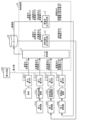
- FIG. 1 is a diagram showing an example of the configuration of an entire system including a power system and a control device for the power system according to an embodiment.
- FIG. 2 is a diagram for explaining the output of the fuel cell power generation system planned by the control device in the embodiment.
- FIG. 3 is a block diagram illustrating an example of a functional configuration of the control device according to the embodiment.
- FIG. 4 is a diagram showing an example of the generated power of the fuel cell power generation apparatus and the charging and discharging power of the storage battery apparatus controlled by the control apparatus in the embodiment.
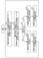
- FIG. 5 is a flowchart illustrating an example of a processing operation of the data acquisition unit according to the embodiment.
- FIG. 6 is a flowchart illustrating an example of a processing operation of the fuel cell output calculation unit in the embodiment.
- FIG. 1 is a diagram showing an example of the configuration of an entire system including a power system and a control device for the power system according to an embodiment.
- FIG. 2 is a diagram for explaining the output of the fuel cell
- FIG. 7 is a flowchart illustrating an example of a processing operation of the storage battery output calculation unit in the embodiment.
- FIG. 8 is a flowchart illustrating an example of a processing operation of the third controller in the embodiment.
- FIG. 9 is a diagram showing an example of effects obtained by the operation modes of the control device in the embodiment.
- a method of operating a power system includes the steps of: planning an output of a fuel cell system for a second period after the first period so as to compensate for a difference between an actual value of power demand during a first period and an actual value of an output of a solar power generation system; charging a storage battery system when the fuel cell system is generating power with the planned output during the second period and the sum of the output of the solar power generation system and the output of the fuel cell system is greater than the power demand; and discharging the storage battery system to meet the power demand when the fuel cell system is generating power with the planned output during the second period and the sum of the output of the solar power generation system and the output of the fuel cell system is less than the power demand, wherein the first period is a period immediately before the second period, the second period is longer than the first period, and the planned output of the fuel cell system is constant during the second period.
- the power system includes, for example, a solar power generation system, a fuel cell system, and a storage battery system.
- the solar power generation system includes a solar power generation device
- the fuel cell system includes a fuel cell
- the storage battery system includes a storage battery.
- the power demand is, for example, the power consumption of the load of the power consumer
- the output of each of the solar power generation system and the fuel cell system is, for example, the generated power.
- the fuel cell system compensates for the difference between the power demand and the amount of photovoltaic power generation in the second period as planned by providing power as a base power source, and compensates for any temporary difference that cannot be compensated for with the power of the storage battery system, which has excellent load following capability.
- this embodiment makes it possible to mutually compensate for the above-mentioned advantages and disadvantages of the fuel cell system and the storage battery system, making it possible to meet the power demand of the load to a greater extent with the power of the power system.
- this embodiment reduces the amount of power purchased from the power grid to meet the power demand of the load.
- the deviation of the fuel cell system output due to the difference between the load power demand and the output of the photovoltaic power generation system in the second period is suppressed, compared to when the output of the fuel cell system in the second period is planned using actual values in a first period that is longer than the second period.
- the output of the fuel cell system is planned taking into account only actual values for a period closer to the second period, compared to when the output of the fuel cell system in the second period is planned using actual values in a first period that is longer than the second period.
- the output of the fuel cell system is maintained constant in the second period that is longer than the first period, deterioration of the fuel cell system can be suppressed.
- the output of the fuel cell system in the second period may be planned to be the median of the difference between the actual value of the power demand in the first period and the actual value of the output of the solar power generation system.
- the difference between each of a number of points in time within a first period is calculated, and the output of the fuel cell system in the second period is set to the median of these differences.
- the difference between the power demand and the output of the photovoltaic power generation system in the second period can be appropriately compensated for by the output of the fuel cell system.
- charging and discharging of the storage battery system can be suppressed.
- the output of the fuel cell system in the second period may be planned to be the average value of the difference between the actual value of the power demand in the first period and the actual value of the output of the solar power generation system.
- the difference between each of a number of points in time within a first period is calculated, and the output of the fuel cell system in the second period is set to the average value of these differences.
- the difference between the power demand and the output of the photovoltaic power generation system in the second period can be appropriately compensated for by the output of the fuel cell system.
- charging and discharging of the storage battery system can be suppressed.
- a control device for a power system includes a storage device that stores an actual value of the power demand during a first period and an actual value of the output of a photovoltaic power generation system, and a controller that plans an output of a fuel cell system during a second period after the first period to compensate for a difference between the actual value of the power demand during the first period and the actual value of the output of the photovoltaic power generation system, and when the fuel cell system is generating power at the planned output during the second period, if the sum of the output of the photovoltaic power generation system and the output of the fuel cell system is greater than the power demand, causes the storage battery system to charge, and when the fuel cell system is generating power at the planned output during the second period, if the sum of the output of the photovoltaic power generation system and the output of the fuel cell system is less than the power demand, causes the storage battery system to discharge so as to meet the power demand, where the first period is a period immediately before the second period, the second period
- each figure is a schematic diagram and is not necessarily a precise illustration. Furthermore, the same components are given the same reference numerals in each figure.
- Fig. 1 is a diagram showing an example of the configuration of an entire system including a power system and a control device for the power system according to the present embodiment.
- power lines are shown by solid lines
- communication lines are shown by dashed lines.
- the power system 200 in this embodiment is connected to the power grid 100 and the load 301 via power lines.
- the power system 200 supplies power to the load 301.
- the power grid 100 has a function of supplying system power and is connected to the load 301 via power lines.
- the system power is also called commercial power, and is, for example, 50 Hz or 60 Hz AC power. Therefore, when the power supplied from the power system 200 is insufficient for the power consumption of the load 301, the power grid 100 supplies the shortage of power to the load 301.
- the surplus power is taken over by the power grid 100, that is, the surplus power is sold as reverse flow power.
- the load 301 in this embodiment is composed of one or more appliances, equipment, devices, etc. that consume power.
- the power consumption of the load 301 is also called power demand.
- the load 301 is provided by power consumers such as factories and facilities.
- the power system 200 includes a solar power generation system a, a fuel cell system b, and a storage battery system c.
- the solar power generation system a includes a first controller 210, a solar power generation device 211, a first PCS (Power Conditioning System) 212, and a first power meter 213.
- PCS Power Conditioning System
- the solar power generation device 211 has, for example, one or more solar power generation units, and converts sunlight into electricity by photoelectric conversion and outputs it.
- the solar power generation unit is, for example, a solar power generation panel.
- the solar power generation device 211 is also simply referred to as a solar cell hereinafter.
- the first PCS 212 converts the power output from the solar power generation device 211 into electricity of the same quality as the grid power and outputs it.
- the first power meter 213 measures the power output from the solar power generation device 211 via the first PCS 212, i.e., the grid power, and outputs a signal indicating the measured power to the control device 10.
- the first controller 210 controls the solar power generation device 211 and the first PCS 212.
- the first controller 210 controls the solar power generation device 211 and the first PCS 212 in response to a command from the control device 10.
- Fuel cell system b includes a second controller 220, a fuel cell power generation device 221, a second PCS 222, and a second power meter 223.
- the fuel cell power generation device 221 has, for example, one or more fuel cell units, and generates electricity by chemically reacting hydrogen with oxygen.
- the hydrogen source used for power generation is, for example, a hydrogen storage tank or hydrogen infrastructure.
- the fuel cell unit is, for example, a fuel cell stack device.
- the fuel cell power generation device 221 is also simply referred to as a fuel cell hereinafter.
- the second PCS 222 converts the power output by the power generation of the fuel cell power generation device 221 into power of the same quality as the grid power and outputs it.
- the second power meter 223 measures the power output from the fuel cell power generation device 221 via the second PCS 222, i.e., the grid power, and outputs a signal indicating the measured power to the control device 10.
- the second controller 220 controls the fuel cell power generation device 221 and the second PCS 222. For example, the second controller 220 adjusts the power output from the fuel cell power generation device 221 and the second PCS 222 in response to a
- the storage battery system c includes a third controller 230, a storage battery device 231, a third PCS 232, and a third power meter 233.
- the storage battery device 231 has, for example, one or more storage battery units, and performs charging or discharging.
- the storage battery unit is, for example, a storage battery pack.
- the storage battery device 231 is also simply referred to as a storage battery hereinafter.
- the third PCS 232 converts the power output by discharging the storage battery device 231 into power of the same quality as the grid power and outputs it. Alternatively, the third PCS 232 converts the grid power and charges the storage battery device 231.
- the third power meter 233 measures the power output from the storage battery device 231 via the third PCS 232, i.e., the grid power, and outputs a signal indicating the measured power to the control device 10.
- the third power meter 233 also measures the power output from the solar power generation device 211 or the fuel cell power generation device 221 and charged to the storage battery device 231, and outputs a signal indicating the measured power to the control device 10.
- the third controller 230 controls the storage battery device 231 and the third PCS 232. For example, the third controller 230 adjusts the power discharged from the storage battery device 231 or the power charged to the storage battery device 231 in response to a command from the control device 10.
- the control device 10 in this embodiment is a control device for the power system 200, and is connected to the fourth power meter 303, the power system 200, and the database 20 via communication lines.
- the control device 10 communicates with each of the fourth power meter 303, the power system 200, and the database 20 via the communication lines.
- the power that is notified, transmitted, instructed, acquired, or received via the communication lines is not the power itself, but data indicating the magnitude of the power, such as watts.
- the fourth power meter 303 measures the power consumption of the load 301.
- Such a control device 10 receives signals indicating the power measured by each of the first power meter 213, the second power meter 223, the third power meter 233, and the fourth power meter 303 at each sampling period. The control device 10 then writes the power indicated by these signals into the database 20. Note that a specific example of the sampling period is 30 seconds or 1 minute, but is not limited to these times.
- the database 20 is a recording medium for recording power values and the like.
- the recording medium may be a hard disk drive, a RAM (Random Access Memory), a ROM (Read Only Memory), or a semiconductor memory.
- the recording medium may be either volatile or non-volatile.
- the database 20 is not provided in the control device 10, but it may be provided in the control device 10.
- FIG. 2 is a diagram for explaining the output of the fuel cell power generation device 221 planned by the control device 10. Specifically, the graph in FIG. 2 shows a schematic representation of the power at each time. The horizontal axis of the graph shows time, and the vertical axis shows power (kW).
- the control device 10 in this embodiment plans the output of the fuel cell power generation device 221 during the control period T2, i.e., the generated power FC of the fuel cell power generation device 221, at a planning point in time of, for example, "12:00".
- the control period T2 is also called the second period.
- the control period T2 is one hour from the planning point in time of "12:00” to the time of "13:00".
- the control device 10 reads out from the database 20 the power consumption D of the load 301 and the power generation PV of the photovoltaic power generation device 211 during the sampling period T1 after the planning time point. That is, the control device 10 reads out the past power consumption D of the load 301 and the past power generation PV of the photovoltaic power generation device 211 obtained for each of the above-mentioned sampling periods during the sampling period T1. Then, the control device 10 plans the power generation FC of the fuel cell power generation device 221 during the control period T2 so as to compensate for the difference between the power consumption D of the load 301 and the power generation PV of the photovoltaic power generation device 211 during the sampling period T1.
- the sampling period T1 is also called the first period.
- the sampling period T1 corresponding to the control period T2 is 15 minutes from time "11:44” to time "11:59". In this case, 15 differences are obtained during the sampling period T1.
- the sampling period T1 corresponding to the control period T2 may be 15 minutes from time "11:44:30" to time "11:59:30". In this case, 30 differences are obtained during the sampling period T1.
- control device 10 controls the fuel cell power generation device 221 and the second PCS 222 via the second controller 220 so that the planned power generation power FC of the fuel cell power generation device 221 is output during the control period T2.
- the control device 10 controls the storage battery device 231 and the third PCS 232 via the third controller 230. Specifically, when the sum of the generated power PV of the solar power generation device 211 and the generated power FC of the fuel cell power generation device 221 is greater than the power consumption D of the load 301, the control device 10 causes the storage battery device 231 to charge. On the other hand, when the sum is less than the power consumption D, the control device 10 causes the storage battery device 231 to discharge so as to satisfy the power consumption D.
- the power consumption D of the load 301 is the power measured by the fourth power meter 303.
- the power generation PV of the solar power generation device 211 is the power output from the solar power generation device 211 via the first PCS 212, and is measured by the first power meter 213. Such power generation PV of the solar power generation device 211 can also be said to be the output of the solar power generation system a or the solar power generation device 211.
- the power generation FC of the fuel cell power generation device 221 is the power output from the fuel cell power generation device 221 via the second PCS 222, and is measured by the second power meter 223.
- Such power generation FC of the fuel cell power generation device 221 can also be said to be the output of the fuel cell system b or the fuel cell power generation device 221.
- the first period which is the sampling period T1
- the second period is longer than the first period
- the planned output of the fuel cell system b is constant during the second period.
- the output of the fuel cell system b corresponds to the generated power FC of the fuel cell power generation device 221.
- the period immediately before the second period is the period from the start point to the end point described below.
- the end point is the most recent measurement point from the above-mentioned planning point among the measurement points of the multiple powers recorded in the database 20.
- the start point is the time of the sampling period T1, for example, 15 minutes, that precedes the end point.
- the first period which is the period immediately before the second period
- the start point of the first period may be after the second period that precedes the planning point, which is the start point of the second period.
- the first period may be any period that is before the start of the second period and is a period that is before the start of the second period or later than the start of the second period.
- the first period is not limited to 15 minutes, and may be 30 minutes or the like, as long as it is shorter than the second period. In other words, the first period may be a period that is 1/2 or less of the second period.
- the output of the fuel cell power generation device 221 in the control period T2 is planned based on the difference between the actual value of the past power consumption D of the load 301 and the actual value of the past power generation PV of the solar power generation device 211. Then, the fuel cell power generation device 221 outputs according to the plan. Therefore, in the operation method in this embodiment, the output of the fuel cell power generation device 221 is prioritized over the output of the storage battery device 231. Therefore, the operation method in this embodiment is also called the fuel cell priority application mode or the hydrogen priority application mode. Such an operation method is applied because when the hydrogen source of the fuel cell power generation device 221 is, for example, a hydrogen storage tank or a hydrogen infrastructure, a larger output capacity can be secured compared to the storage battery device 231.
- FIG. 3 is a block diagram showing an example of the functional configuration of the control device 10. Note that in FIG. 3, the first PCS 212, the second PCS 222, and the third PCS 232 are omitted for simplicity's sake. Also, in FIG. 3, communication lines are shown with solid lines, and power lines are shown with dashed lines, for ease of understanding of the communication relationships between the components.
- the control device 10 in this embodiment includes a data acquisition unit 11, a fuel cell output calculation unit 12, and a storage battery output calculation unit 13.
- the data acquisition unit 11 acquires signals indicating the four powers from the fourth power meter 303, the first power meter 213, the second power meter 223, and the third power meter 233 for each sampling period described above. The data acquisition unit 11 then writes the numerical values of each of the four powers into the database 20 as actual values.
- the four powers are the power consumption D of the load 301, the power generated PV of the solar power generation device 211, the power generated FC of the fuel cell power generation device 221, and the discharge power Bd or charge power Bc of the storage battery device 231.
- the discharge power Bd and charge power Bc are collectively referred to as charge/discharge power SB.
- the discharge power Bd of the storage battery device 231 is the power discharged from the storage battery device 231 via the third PCS 232, and is the power measured by the third power meter 233.
- the charge power Bc of the storage battery device 231 in this embodiment is the power charged to the storage battery device 231 via the third PCS 232 from the solar power generation device 211 or the fuel cell power generation device 221, etc., and is the power measured by the third power meter 233.
- the fuel cell output calculation unit 12 reads out from the database 20 the power consumption D of the load 301 and the power generation PV of the solar power generation device 211 in the sampling period T1 immediately before the planning time. The fuel cell output calculation unit 12 then uses the power consumption D and the power generation PV to calculate the power generation FC of the fuel cell power generation device 221 in the control period T2. This allows the power generation FC to be planned.
- the fuel cell output calculation unit 12 in this embodiment plans the output of the fuel cell system b, i.e., the power generation FC, in the second period, which is the control period T2 after the first period, so as to compensate for the difference between the actual value of the power demand in the first period, which is the sampling period T1, and the actual value of the output of the solar power generation system a.
- the output of the solar power generation system a corresponds to the power generation PV of the solar power generation device 211.
- the fuel cell output calculation unit 12 instructs the second controller 220 to generate the power generation FC via a communication line.
- the second controller 220 controls the fuel cell power generation device 221 and the second PCS 222 according to instructions from the fuel cell output calculation unit 12.
- the storage battery output calculation unit 13 reads out the latest three powers from the database 20 for each storage battery command period.
- the three powers are the power consumption D of the load 301, the power generation power PV of the solar power generation device 211, and the power generation power FC of the fuel cell power generation device 221.
- a specific example of the storage battery command period is one minute.
- the storage battery output calculation unit 13 calculates the power to be discharged or charged by the storage battery device 231 based on the three read powers.
- the storage battery output calculation unit 13 commands the calculated power to the third controller 230 via a communication line.
- the storage battery output calculation unit 13 outputs a discharge power command value Bd' or a charge power command value Bc' indicating the calculated power to the third controller 230.
- the third controller 230 controls the storage battery device 231 and the third PCS 232 according to instructions from the storage battery output calculation unit 13.
- Figure 4 shows an example of the generated power FC of the fuel cell power generation system 221 and the charge/discharge power SB of the storage battery device 231 controlled by the control device 10.
- (a) of Figure 4 is a graph that shows a schematic representation of the time change in the power consumption D of the load 301 and the generated power PV of the solar power generation system 211.
- (b) of Figure 4 is a graph that shows a schematic representation of the time change in the generated power FC of the fuel cell power generation system 221.
- (c) of Figure 4 is a graph that shows a schematic representation of the time change in the charge/discharge power SB of the storage battery device 231. Note that the horizontal axis of these graphs indicates time, and the vertical axis indicates power.
- the power consumption D of the load 301 and the power generation PV of the solar power generation device 211 change between the time "00:00" and the time "24:00".
- the fuel cell output calculation unit 12 of the control device 10 plans the power generation FC of the fuel cell power generation device 221 in the control period T2 after the time ta1 at the time ta1, which is the planning time point.
- the fuel cell output calculation unit 12 calculates the power generation FC so that the power consumption D of the load 301 in the sampling period T1 is equal to the sum of the power generation PV of the solar power generation device 211 and the power generation FC of the fuel cell power generation device 221.
- This calculated power generation FC is planned as the power generation FC of the fuel cell power generation device 221 in the control period T2 after the time ta1. This makes it possible to suppress the reverse flow power and power purchases, i.e., surplus power and shortage power, in the control period T2.
- the fuel cell output calculation unit 12 repeatedly calculates the generated power FC using the control period T2 as one cycle, and commands the second controller 220 to generate the generated power FC each time the generated power FC is calculated.
- the second controller 220 controls the fuel cell power generation device 221 so that the generated power FC is generated.
- the fuel cell power generation device 221 has a rated output and a minimum output.
- the rated output is 500 kW and the minimum output is 150 kW. Therefore, when the generated power FC commanded by the fuel cell output calculation unit 12 exceeds the rated output, the second controller 220 may cause the fuel cell power generation device 221 to generate the power at the rated output. And when the generated power FC commanded by the fuel cell output calculation unit 12 falls below the minimum output, the second controller 220 may cause the fuel cell power generation device 221 to generate the power at the minimum output.
- the storage battery output calculation unit 13 calculates the charge/discharge power SB of the storage battery device 231 for each storage battery command period. At this time, the storage battery output calculation unit 13 calculates the charge/discharge power SB so that the sum of the latest power generation power PV of the photovoltaic power generation device 211, the latest power generation power FC of the fuel cell power generation device 221, and the charge/discharge power SB of the storage battery device 231 is equal to the latest power consumption D of the load 301, as shown in (e) of FIG. 4. Furthermore, the storage battery output calculation unit 13 commands the third controller 230 to discharge or charge the charge/discharge power SB.
- the storage battery output calculation unit 13 outputs the discharge power command value Bd' or the charge power command value Bc' to the third controller 230.
- the third controller 230 controls the storage battery device 231 so that the charge/discharge power SB is discharged or charged. This makes it possible to suppress instantaneous reverse flow power and power purchases during control period T2, i.e., instantaneous surplus power and power shortages.
- the storage battery output calculation unit 13 charges the storage battery system c.
- the storage battery output calculation unit 13 discharges the storage battery system c to meet the power demand.
- the charging and discharging of the storage battery system c corresponds to the charging and discharging of the storage battery device 231.
- the control device 10 in this embodiment can be said to be a device equipped with a memory and a controller.
- the memory is a recording medium that stores the power consumption D of the load 301 during the sampling period T1 and the power generation PV of the photovoltaic power generation device 211, which are read out by the fuel cell output calculation unit 12.
- the recording medium is a hard disk drive, RAM, ROM, or semiconductor memory.
- the recording medium may be volatile or non-volatile. That is, the memory stores the actual value of the power demand during the first period and the actual value of the output of the photovoltaic power generation system a.
- the controller has the functions of the fuel cell output calculation unit 12 and the storage battery output calculation unit 13.
- the controller functions as the fuel cell output calculation unit 12 to plan the output of the fuel cell system b during the second period so as to compensate for the above-mentioned difference. Furthermore, the controller functions as the above-mentioned storage battery output calculation unit 13 to charge and discharge the storage battery system c.
- the control device 10 in this embodiment may include a database 20 as described above.
- the storage device may be used as the database 20.
- each component of the control device 10 such as the data acquisition unit 11 and the controller, may be configured as dedicated hardware or circuitry. Furthermore, each component may be realized by executing a software program. That is, each component may be realized by a program execution unit such as a CPU (Central Processing Unit) or processor reading and executing a software program recorded on a recording medium such as a hard disk or semiconductor memory. Furthermore, the control device 10 may be configured with a single controller that performs centralized control, or may be configured with multiple controllers that cooperate with each other to perform distributed control.
- a program execution unit such as a CPU (Central Processing Unit) or processor reading and executing a software program recorded on a recording medium such as a hard disk or semiconductor memory.
- the control device 10 may be configured with a single controller that performs centralized control, or may be configured with multiple controllers that cooperate with each other to perform distributed control.
- FIG. 5 is a flowchart showing an example of the processing operation of the data acquisition unit 11.
- the data acquisition unit 11 executes the processes of steps S1 to S4 and S6 for each sampling period. That is, the data acquisition unit 11 acquires a signal indicating the power consumption D of the load 301 from the fourth power meter 303 (step S1). Furthermore, the data acquisition unit 11 acquires a signal indicating the power generated PV of the photovoltaic power generation device 211 from the first power meter 213 (step S2). Furthermore, the data acquisition unit 11 acquires a signal indicating the power generated FC of the fuel cell power generation device 221 from the second power meter 223 (step S3). Furthermore, the data acquisition unit 11 acquires a signal indicating the discharge power Bd or charge power Bc of the storage battery device 231 from the third power meter 233 (step S4).
- the data acquisition unit 11 writes the power consumption D of the load 301 indicated by the signal acquired in step S1 and the power of the three batteries indicated by the signals acquired in steps S2 to S4 into the database 20 (step S6).
- the power of the three batteries is the generated power PV of the solar power generation device 211, the generated power FC of the fuel cell power generation device 221, and the discharge power Bd or charge power Bc of the storage battery device 231.
- FIG. 6 is a flowchart showing an example of the processing operation of the fuel cell output calculation unit 12.
- the fuel cell output calculation unit 12 reads out from the database 20 the power consumption D of the load 301 and the power generation PV of the solar power generation device 211 for each of a number of measurement points in the sampling period T1 immediately prior to the planning point (step S11).
- the fuel cell output calculation unit 12 calculates, for each of the multiple measurement time points, the difference between the power consumption D of the load 301 and the power generation PV of the solar power generation device 211 at that measurement time point. In other words, the fuel cell output calculation unit 12 calculates the difference at each of the multiple measurement time points by subtracting the power generation PV at that measurement time point from the power consumption D at that measurement time point. The fuel cell output calculation unit 12 then calculates the median of the differences at the multiple measurement time points as difference value 1 (step S12). Note that in this embodiment, the median of the differences at the multiple measurement time points is an example of difference value 1, and difference value 1 may be the average value of these differences.
- the fuel cell output calculation unit 12 plans the output of the fuel cell system b in the second period to be the median of the difference between the actual value of the power demand in the first period and the actual value of the output of the solar power generation system a.
- the fuel cell output calculation unit 12 plans the output of the fuel cell system b in the second period to be the average of the difference between the actual value of the power demand in the first period and the actual value of the output of the solar power generation system a.
- the fuel cell output calculation unit 12 judges whether or not the difference value 1 is a positive value (step S13).
- the fuel cell output calculation unit 12 judges that the difference value 1 is a positive value (YES in step S13)
- the fuel cell output calculation unit 12 judges that the difference value 1 is not a positive value (NO in step S13)
- the generated power PV of the solar power generation device 211 is equal to or greater than the power consumption D of the load 301, and the power supplied to the load 301 is not insufficient, so the generated power FC of the fuel cell power generation device 221 is set to 0. In other words, the generated power FC is set so that the fuel cell power generation device 221 does not output.
- the fuel cell output calculation unit 12 commands the second controller 220 to generate the power FC set in step S14 or S15 (step S16).
- the second controller 220 upon receiving such a command, controls the fuel cell power generation device 221 and the second PCS 222.
- the power generation power FC set in step S14 or S15 is output from the fuel cell power generation device 221 via the second PCS 222.
- the fuel cell output calculation unit 12 determines whether or not the control period T2 has elapsed since the command in step S16 was issued (step S17). If the fuel cell output calculation unit 12 determines that the control period T2 has not elapsed (NO in step S17), it repeatedly executes the process of step S17. On the other hand, if the fuel cell output calculation unit 12 determines that the control period T2 has elapsed (YES in step S17), it repeatedly executes the process of step S11. As a result, the processes of steps S11 to S17 are repeatedly executed for each control period T2.
- FIG. 7 is a flowchart showing an example of the processing operation of the storage battery output calculation unit 13.
- the storage battery output calculation unit 13 determines whether or not the difference value 2 is a positive value (step S23). If the storage battery output calculation unit 13 determines that the difference value 2 is a positive value (YES in step S23), it sets the discharge power command value Bd' of the storage battery device 231 to the difference value 2 (step S24). Then, the storage battery output calculation unit 13 commands the third controller 230 to discharge the discharge power command value Bd' (step S25).
- the storage battery output calculation unit 13 determines that the difference value 2 is not a positive value (NO in step S23), it sets the charging power command value Bc' of the storage battery device 231 to the absolute value of the difference value 2 (step S26). Then, the storage battery output calculation unit 13 commands the third controller 230 to charge the charging power command value Bc' (step S27).
- FIG. 8 is a flowchart showing an example of the processing operation of the third controller 230. Specifically, the flowchart in FIG. 8 shows an example of the processing operation performed by the third controller 230 after the command in step S25 or S27 in the flowchart in FIG. 7 is issued.
- the third controller 230 determines whether the command, i.e., the command value, is a discharge power command value Bd' or a charge power command value Bc' (step S31).
- the third controller 230 determines that the command value is a discharge power command value Bd' (Bd' in step S31)
- the SOC of the battery device 231 is also called the battery SOC.
- the SOC lower limit is a predetermined value, and is stored in, for example, the third controller 230.
- the battery SOC being above the SOC lower limit means that the battery SOC is greater than the SOC lower limit. In other words, in step S32, it is determined whether the battery SOC is greater than the SOC lower limit.
- the third controller 230 determines whether the storage battery SOC is above the SOC lower limit (YES in step S32), it further determines whether the discharge power command value Bd' exceeds the rated output of the storage battery device 231 (step S33).
- the third controller 230 determines that the discharge power command value Bd' does not exceed the rated output (NO in step S33)
- the discharge power Bd of the storage battery device 231 is the power discharged from the storage battery device 231 via the third PCS 232. In other words, the storage battery device 231 discharges the difference value 2 via the third PCS 232.
- the third controller 230 determines that the discharge power command value Bd' exceeds the rated output (YES in step S33), it controls the storage battery device 231 and the third PCS 232 so that the discharge power Bd of the storage battery device 231 becomes the rated output (step S35). In other words, the storage battery device 231 discharges at the rated output via the third PCS 232. Also, if the third controller 230 determines that the storage battery SOC is not higher than the SOC lower limit value (NO in step S32), it controls the storage battery device 231 and the third PCS 232 so that the discharge power Bd of the storage battery device 231 becomes 0 (step S36). In other words, the storage battery device 231 does not discharge.
- step S31 when it is determined that the command value is the charge power command value Bc' (Bc' in step S31), the third controller 230 determines whether the storage battery SOC is below the SOC upper limit (step S37).
- the SOC upper limit is a predetermined value, and is stored in the third controller 230, for example.
- the storage battery SOC being below the SOC upper limit means that the storage battery SOC is smaller than the SOC upper limit.
- step S37 it is determined whether the storage battery SOC is smaller than the SOC upper limit.
- the third controller 230 determines whether the storage battery SOC is below the SOC upper limit (YES in step S37), it further determines whether the charging power command value Bc' exceeds the rated output of the storage battery device 231 (step S38).
- the third controller 230 determines that the charging power command value Bc' does not exceed the rated output (NO in step S38)
- the charging power Bc of the storage battery device 231 is the power charged to the storage battery device 231 via the third PCS 232. In other words, the storage battery device 231 charges only the absolute value of the difference value 2.
- the third controller 230 determines that the charging power command value Bc' exceeds the rated output (YES in step S38), it controls the storage battery device 231 and the third PCS 232 so that the charging power Bc of the storage battery device 231 becomes the rated output (step S40). In other words, the storage battery device 231 performs charging at the rated output. Also, if the third controller 230 determines that the storage battery SOC is not below the SOC upper limit value (NO in step S37), it controls the storage battery device 231 and the third PCS 232 so that the charging power Bc of the storage battery device 231 becomes 0 (step S41). In other words, the storage battery device 231 does not charge.
- the third controller 230 may execute each step included in the flowchart of FIG. 8 for each storage battery unit.
- the discharge power command value Bd' and the charge power command value Bc' used for each storage battery unit may be values obtained by dividing the overall command value of the storage battery device 231 by the number of storage battery units included in the storage battery device 231.
- the third controller 230 has a function of controlling the discharge power Bd and the charge power Bc of the storage battery device 231 based on the charge power command value Bc' and the discharge power command value Bd'.
- the storage battery output calculation unit 13 of the control device 10 may also have this function. In other words, the storage battery output calculation unit 13 may execute each step included in the flowchart shown in FIG. 8. In this case, the data acquisition unit 11 acquires the storage battery SOC from the third controller 230 at the same timing as the power consumption D of the load 301 and the generated power PV of the solar power generation device 211, and stores it in the database 20. Then, in step S21 of FIG.
- the storage battery output calculation unit 13 further reads out the latest storage battery SOC from the database 20, and uses the read storage battery SOC in steps S32 and S37 of FIG. 8. Meanwhile, the third controller 230 controls the storage battery device 231 and the third PCS 232 according to the discharge power Bd and the charge power Bc determined by the storage battery output calculation unit 13 in the processing of steps S34 to S36 and S39 to S41.
- FIG. 9 is a diagram showing an example of the effect obtained by the operation mode of the control device 10 in this embodiment.
- the effect obtained by the operation mode of the control device 10 is shown in comparison with the operation mode of a comparative example.
- the average value of the difference between the power consumption D of the load 301 and the power generation PV of the photovoltaic power generation device 211 is calculated for each time period in the past year. Then, this average value is planned as the power generation FC of the fuel cell power generation device 221 for that time period. For example, the average value of the above-mentioned difference is calculated for each time period of midnight, 1:00, 2:00, etc. for the past year from January 1st to December 31st. In other words, the average value of 365 points of differences is calculated for each time period. Then, for example, the average value for the midnight hours is planned as the power generation FC of the fuel cell power generation device 221 for the midnight hours from the current time onwards.
- the annual on-site self-sufficiency rate is 63.3%, and the annual grid energy rate is 36.7%.
- the on-site self-sufficiency rate is the ratio of the amount of power supplied from the power system 200 and consumed by the load 301 to the total amount of power consumed by the load 301.
- the grid energy rate is the ratio of the amount of power supplied from the power system 100 and consumed by the load 301 to the total amount of power consumed by the load 301.
- an annual on-site self-sufficiency rate of 100% can be obtained, and an annual grid power rate of 0% can be obtained.
- the on-site self-sufficiency rate of 100% and the grid energy rate of 0% are values obtained when the power system 200 has the following configuration. That is, in this configuration, the solar power generation device 211 has 1800 solar power generation panels, and the maximum output of the solar power generation device 211 as a whole is 500 kW.
- the fuel cell power generation device 221 has 100 hydrogen fuel cells, and the maximum output or rated output of the fuel cell power generation device 221 as a whole is 500 kW.
- the hydrogen fuel cell is also called a fuel cell stack device.
- the control range of the fuel cell power generation device 221 is from the rated output to 0 kW. Note that the maximum output of each hydrogen fuel cell is 5 kW.
- the control period T2 is one hour.
- the maximum output or rated output of the storage battery device 231 is 300 kW, and the capacity of the storage battery device 231 is 1000 kWh.
- the output of fuel cell system b is planned for the second period, which is the control period T2 after the first period, so as to compensate for the difference between the actual value of the power demand during the first period, which is the sampling period T1, and the actual value of the output of photovoltaic power generation system a. Furthermore, when fuel cell system b is generating power at the planned output during the second period, if the sum of the output of photovoltaic power generation system a and the output of fuel cell system b is greater than the power demand, charging is performed by storage battery system c.
- the fuel cell system b compensates for the difference between the power demand and the photovoltaic power generation during the second period, which is the control period T2, with power as a base power source as planned, and compensates for the temporary difference that cannot be compensated for with the power of the storage battery system c, which has excellent load following.
- the above-mentioned advantages and disadvantages of the fuel cell system b and the storage battery system c are mutually compensated for, and it becomes possible to meet the power demand of the load with the power of the power system 200 more.
- this embodiment reduces the purchase of power from the power grid 100 to meet the power demand of the load.
- the deviation in the output of the fuel cell system due to the difference between the load's power demand and the output of the photovoltaic power generation system a during the second period is suppressed, compared to when the output of the fuel cell system during the second period is planned using actual values during the first period that is longer than the second period.
- the output of the fuel cell system b is planned taking into account only actual values during a period closer to the second period, compared to when the output of the fuel cell system b during the second period is planned using actual values during the first period that is longer than the second period.
- the output of the fuel cell power generation device 221 during that long period is maintained constant, deterioration of the fuel cell power generation device 221 can be suppressed.
- step S12 of FIG. 6 the median of the differences is used, so in a situation where the actual value for the first period continues in the second period, the difference between the power demand in the second period and the output of the photovoltaic power generation device 211 can be appropriately compensated for by the output of the fuel cell power generation device 221. As a result, the charging and discharging of the storage battery device 231 can be suppressed.
- the difference between the power demand during the second period and the output of the photovoltaic power generation device 211 can be appropriately compensated for by the output of the fuel cell power generation device 221.
- the charging and discharging of the storage battery device 231 can be suppressed.
- control device 10 communicates with the database 20, the power system 200, and the fourth power meter 303 via communication lines, but the communication is not limited to wired communication and may be wireless communication.
- the wireless communication may be performed using Wi-Fi (registered trademark), Bluetooth (registered trademark), ZigBee (registered trademark), or a specific low-power radio.
- each component may be configured with dedicated hardware, or may be realized by executing a software program suitable for each component.
- Each component may be realized by a program execution unit such as a CPU or processor reading and executing a software program recorded on a recording medium such as a hard disk or semiconductor memory.
- the software that realizes the control device 10 and power system 200 of the above embodiment is a computer program that causes a computer to execute each step of the flowcharts shown in each of Figures 5 to 8.
- the at least one device is a computer system consisting of a microprocessor, ROM, RAM, a hard disk unit, a display unit, a keyboard, a mouse, etc.
- a computer program is stored in the RAM or hard disk unit.
- the at least one device achieves its functions by the microprocessor operating in accordance with the computer program.
- a computer program is composed of a combination of multiple instruction codes that indicate commands for a computer to achieve a specified function.
- a system LSI is an ultra-multifunctional LSI manufactured by integrating multiple components on a single chip, and specifically, is a computer system comprising a microprocessor, ROM, RAM, etc.
- a computer program is stored in the RAM. The system LSI achieves its functions when the microprocessor operates in accordance with the computer program.
- Some or all of the components constituting at least one of the above devices may be composed of an IC card or a standalone module that is detachable from the device.
- the IC card or module is a computer system composed of a microprocessor, ROM, RAM, etc.
- the IC card or module may include the above-mentioned ultra-multifunction LSI.
- the IC card or module achieves its functions when the microprocessor operates according to a computer program. This IC card or module may be tamper-resistant.
- the present disclosure may be the methods described above. It may also be a computer program that implements these methods using a computer, or a digital signal that comprises a computer program.
- the present disclosure may also be a computer program or digital signal recorded on a computer-readable recording medium, such as a flexible disk, a hard disk, a CD (Compact Disc)-ROM, a DVD, a DVD-ROM, a DVD-RAM, a BD (Blu-ray (registered trademark) Disc), a semiconductor memory, etc. It may also be a digital signal recorded on such a recording medium.
- a computer-readable recording medium such as a flexible disk, a hard disk, a CD (Compact Disc)-ROM, a DVD, a DVD-ROM, a DVD-RAM, a BD (Blu-ray (registered trademark) Disc), a semiconductor memory, etc. It may also be a digital signal recorded on such a recording medium.
- the present disclosure may also involve the transmission of computer programs or digital signals via telecommunications lines, wireless or wired communication lines, networks such as the Internet, data broadcasting, etc.
- the program or digital signal may also be implemented by another independent computer system by recording it on a recording medium and transferring it, or by transferring the program or digital signal via a network, etc.
- the power system operation method disclosed herein can be applied to devices or systems that control, for example, solar power generation systems, fuel cell systems, and battery storage systems.
- Control device 11 Data acquisition unit 12 Fuel cell output calculation unit 13 Storage battery output calculation unit 20 Database 100 Power system 200 Power system 210 First controller 211 Photovoltaic power generation device 212 First PCS 213 First power meter 220 Second controller 221 Fuel cell power generation device 222 Second PCS 223 Second power meter 230 Third controller 231 Storage battery device 232 Third PCS 233 Third power meter 301 Load 303 Fourth power meter a Photovoltaic power generation system b Fuel cell system c Storage battery system T1 Sampling period (first period) T2 Control period (second period)
Landscapes
- Engineering & Computer Science (AREA)
- Power Engineering (AREA)
- Supply And Distribution Of Alternating Current (AREA)
- Fuel Cell (AREA)
- Charge And Discharge Circuits For Batteries Or The Like (AREA)
Priority Applications (4)
| Application Number | Priority Date | Filing Date | Title |
|---|---|---|---|
| JP2024505176A JP7507388B1 (ja) | 2022-11-02 | 2023-09-20 | 電力システムの運転方法、および電力システムの制御装置 |
| CN202380073944.9A CN120077539A (zh) | 2022-11-02 | 2023-09-20 | 电力系统的运行方法以及电力系统的控制装置 |
| EP23885393.1A EP4614753A4 (en) | 2022-11-02 | 2023-09-20 | METHOD FOR OPERATION OF A FEEDING SYSTEM AND CONTROL DEVICE FOR THE FEEDING SYSTEM |
| US19/175,718 US20250260232A1 (en) | 2022-11-02 | 2025-04-10 | Method for operating power system and control apparatus for power system |
Applications Claiming Priority (2)
| Application Number | Priority Date | Filing Date | Title |
|---|---|---|---|
| JP2022176014 | 2022-11-02 | ||
| JP2022-176014 | 2022-11-02 |
Related Child Applications (1)
| Application Number | Title | Priority Date | Filing Date |
|---|---|---|---|
| US19/175,718 Continuation US20250260232A1 (en) | 2022-11-02 | 2025-04-10 | Method for operating power system and control apparatus for power system |
Publications (1)
| Publication Number | Publication Date |
|---|---|
| WO2024095628A1 true WO2024095628A1 (ja) | 2024-05-10 |
Family
ID=90930226
Family Applications (1)
| Application Number | Title | Priority Date | Filing Date |
|---|---|---|---|
| PCT/JP2023/034120 Ceased WO2024095628A1 (ja) | 2022-11-02 | 2023-09-20 | 電力システムの運転方法、および電力システムの制御装置 |
Country Status (5)
| Country | Link |
|---|---|
| US (1) | US20250260232A1 (https=) |
| EP (1) | EP4614753A4 (https=) |
| JP (1) | JP7507388B1 (https=) |
| CN (1) | CN120077539A (https=) |
| WO (1) | WO2024095628A1 (https=) |
Families Citing this family (1)
| Publication number | Priority date | Publication date | Assignee | Title |
|---|---|---|---|---|
| JP7630111B1 (ja) * | 2023-09-29 | 2025-02-17 | パナソニックIpマネジメント株式会社 | 計画方法、計画装置及び電力システム |
Citations (4)
| Publication number | Priority date | Publication date | Assignee | Title |
|---|---|---|---|---|
| WO2013141039A1 (ja) * | 2012-03-22 | 2013-09-26 | 株式会社 東芝 | エネルギー管理装置、エネルギー管理方法およびプログラム |
| WO2015004849A1 (ja) * | 2013-07-09 | 2015-01-15 | パナソニックIpマネジメント株式会社 | 電力制御方法、電力制御装置、電力制御システム |
| WO2016038994A1 (ja) * | 2014-09-12 | 2016-03-17 | 株式会社東芝 | グラムを記憶した記憶媒体 |
| WO2017013751A1 (ja) | 2015-07-21 | 2017-01-26 | 株式会社 東芝 | 電力供給システム、制御装置、および電力供給方法 |
Family Cites Families (2)
| Publication number | Priority date | Publication date | Assignee | Title |
|---|---|---|---|---|
| JP7059583B2 (ja) * | 2017-11-20 | 2022-04-26 | 株式会社Ihi | エネルギーマネジメントシステム、電力需給計画最適化方法、および電力需給計画最適化プログラム |
| CN111953016B (zh) * | 2020-07-27 | 2024-02-09 | 江苏大学 | 一种移动式多能源微电网控制方法及系统 |
-
2023
- 2023-09-20 CN CN202380073944.9A patent/CN120077539A/zh active Pending
- 2023-09-20 WO PCT/JP2023/034120 patent/WO2024095628A1/ja not_active Ceased
- 2023-09-20 EP EP23885393.1A patent/EP4614753A4/en active Pending
- 2023-09-20 JP JP2024505176A patent/JP7507388B1/ja active Active
-
2025
- 2025-04-10 US US19/175,718 patent/US20250260232A1/en active Pending
Patent Citations (4)
| Publication number | Priority date | Publication date | Assignee | Title |
|---|---|---|---|---|
| WO2013141039A1 (ja) * | 2012-03-22 | 2013-09-26 | 株式会社 東芝 | エネルギー管理装置、エネルギー管理方法およびプログラム |
| WO2015004849A1 (ja) * | 2013-07-09 | 2015-01-15 | パナソニックIpマネジメント株式会社 | 電力制御方法、電力制御装置、電力制御システム |
| WO2016038994A1 (ja) * | 2014-09-12 | 2016-03-17 | 株式会社東芝 | グラムを記憶した記憶媒体 |
| WO2017013751A1 (ja) | 2015-07-21 | 2017-01-26 | 株式会社 東芝 | 電力供給システム、制御装置、および電力供給方法 |
Non-Patent Citations (1)
| Title |
|---|
| See also references of EP4614753A4 |
Also Published As
| Publication number | Publication date |
|---|---|
| CN120077539A (zh) | 2025-05-30 |
| JPWO2024095628A1 (https=) | 2024-05-10 |
| US20250260232A1 (en) | 2025-08-14 |
| JP7507388B1 (ja) | 2024-06-28 |
| EP4614753A4 (en) | 2026-01-21 |
| EP4614753A1 (en) | 2025-09-10 |
Similar Documents
| Publication | Publication Date | Title |
|---|---|---|
| US11757404B2 (en) | Coordinated control of renewable electric generation resource and charge storage device | |
| JP7420272B2 (ja) | 電力調整方法および電力調整装置 | |
| CN105684257B (zh) | 用于控制微电网的操作的微电网能量管理系统和方法 | |
| JP6615602B2 (ja) | バッテリエネルギー貯蔵システムを含む電力供給システム | |
| JP5998454B2 (ja) | 制御装置、制御方法および制御システム | |
| EP2495576B1 (en) | Method for controlling secondary cell and power storage device | |
| US11342751B2 (en) | Power management system for customer connected to power network and having load apparatus and power storage apparatus | |
| JP2009284586A (ja) | 電力システムおよびその制御方法 | |
| WO2013172022A1 (ja) | 周波数制御方法、周波数制御システム、周波数制御装置、及びプログラム | |
| WO2014103351A1 (ja) | 電力制御装置、電力制御方法、プログラム、およびエネルギーマネジメントシステム | |
| WO2012057307A1 (ja) | 電力管理用の制御装置 | |
| US12556003B2 (en) | Energy storage system for optimum operation of demand response resource and operating method thereof | |
| JP6688981B2 (ja) | 蓄電池制御装置 | |
| JP2006311707A (ja) | 自然エネルギー発電システム | |
| JP7507388B1 (ja) | 電力システムの運転方法、および電力システムの制御装置 | |
| JP7710929B2 (ja) | バッテリーユニットの制御装置 | |
| KR101299269B1 (ko) | 배터리 에너지 저장 시스템 | |
| CN120601548B (zh) | 基于电化学储能电站的有功功率调控方法、装置、设备及介质 | |
| JP2023157131A (ja) | 上位電力管理装置、電力融通制御方法、及び電力融通制御プログラム | |
| Desdouits et al. | Multisource elevator energy optimization and control | |
| KR102084678B1 (ko) | 태양광 연계형 ess 시스템의 방전 스케줄 제어방법 | |
| WO2024095629A1 (ja) | 電力システムの運転方法、および電力システムの制御装置 | |
| CN117728462B (zh) | 一种构网型储能并网控制方法 | |
| Dos Santos et al. | Prediction-based economic dispatch and online optimization for grid-connected DC microgrid | |
| JP2025089219A (ja) | 電力制御システムおよび電力制御方法 |
Legal Events
| Date | Code | Title | Description |
|---|---|---|---|
| ENP | Entry into the national phase |
Ref document number: 2024505176 Country of ref document: JP Kind code of ref document: A |
|
| 121 | Ep: the epo has been informed by wipo that ep was designated in this application |
Ref document number: 23885393 Country of ref document: EP Kind code of ref document: A1 |
|
| WWE | Wipo information: entry into national phase |
Ref document number: 202380073944.9 Country of ref document: CN |
|
| WWP | Wipo information: published in national office |
Ref document number: 202380073944.9 Country of ref document: CN |
|
| WWE | Wipo information: entry into national phase |
Ref document number: 2023885393 Country of ref document: EP |
|
| NENP | Non-entry into the national phase |
Ref country code: DE |
|
| ENP | Entry into the national phase |
Ref document number: 2023885393 Country of ref document: EP Effective date: 20250602 |
|
| WWP | Wipo information: published in national office |
Ref document number: 2023885393 Country of ref document: EP |