WO2024095628A1 - Method for operating power system and power system control device - Google Patents
Method for operating power system and power system control device Download PDFInfo
- Publication number
- WO2024095628A1 WO2024095628A1 PCT/JP2023/034120 JP2023034120W WO2024095628A1 WO 2024095628 A1 WO2024095628 A1 WO 2024095628A1 JP 2023034120 W JP2023034120 W JP 2023034120W WO 2024095628 A1 WO2024095628 A1 WO 2024095628A1
- Authority
- WO
- WIPO (PCT)
- Prior art keywords
- power
- period
- output
- fuel cell
- power generation
- Prior art date
Links
- 238000000034 method Methods 0.000 title claims abstract description 26
- 238000010248 power generation Methods 0.000 claims abstract description 220
- 239000000446 fuel Substances 0.000 claims abstract description 197
- 238000007599 discharging Methods 0.000 claims description 13
- 238000004364 calculation method Methods 0.000 description 61
- 238000005070 sampling Methods 0.000 description 26
- UFHFLCQGNIYNRP-UHFFFAOYSA-N Hydrogen Chemical compound [H][H] UFHFLCQGNIYNRP-UHFFFAOYSA-N 0.000 description 14
- 238000004891 communication Methods 0.000 description 14
- 239000001257 hydrogen Substances 0.000 description 14
- 229910052739 hydrogen Inorganic materials 0.000 description 14
- 238000004590 computer program Methods 0.000 description 13
- 238000012545 processing Methods 0.000 description 11
- 238000010586 diagram Methods 0.000 description 10
- 230000006870 function Effects 0.000 description 10
- 238000005259 measurement Methods 0.000 description 10
- 230000008901 benefit Effects 0.000 description 8
- 230000008569 process Effects 0.000 description 5
- 239000004065 semiconductor Substances 0.000 description 5
- 230000008859 change Effects 0.000 description 4
- 230000000694 effects Effects 0.000 description 4
- 230000000052 comparative effect Effects 0.000 description 3
- 230000005611 electricity Effects 0.000 description 3
- 238000004519 manufacturing process Methods 0.000 description 3
- 230000004044 response Effects 0.000 description 3
- 230000006866 deterioration Effects 0.000 description 2
- QVGXLLKOCUKJST-UHFFFAOYSA-N atomic oxygen Chemical compound [O] QVGXLLKOCUKJST-UHFFFAOYSA-N 0.000 description 1
- 230000005540 biological transmission Effects 0.000 description 1
- 238000006243 chemical reaction Methods 0.000 description 1
- 230000003750 conditioning effect Effects 0.000 description 1
- 230000010354 integration Effects 0.000 description 1
- 239000000463 material Substances 0.000 description 1
- 238000012986 modification Methods 0.000 description 1
- 230000004048 modification Effects 0.000 description 1
- 239000001301 oxygen Substances 0.000 description 1
- 229910052760 oxygen Inorganic materials 0.000 description 1
Images


Classifications
-
- H—ELECTRICITY
- H02—GENERATION; CONVERSION OR DISTRIBUTION OF ELECTRIC POWER
- H02J—CIRCUIT ARRANGEMENTS OR SYSTEMS FOR SUPPLYING OR DISTRIBUTING ELECTRIC POWER; SYSTEMS FOR STORING ELECTRIC ENERGY
- H02J3/00—Circuit arrangements for ac mains or ac distribution networks
-
- H—ELECTRICITY
- H02—GENERATION; CONVERSION OR DISTRIBUTION OF ELECTRIC POWER
- H02J—CIRCUIT ARRANGEMENTS OR SYSTEMS FOR SUPPLYING OR DISTRIBUTING ELECTRIC POWER; SYSTEMS FOR STORING ELECTRIC ENERGY
- H02J3/00—Circuit arrangements for ac mains or ac distribution networks
- H02J3/28—Arrangements for balancing of the load in a network by storage of energy
- H02J3/32—Arrangements for balancing of the load in a network by storage of energy using batteries with converting means
-
- H—ELECTRICITY
- H02—GENERATION; CONVERSION OR DISTRIBUTION OF ELECTRIC POWER
- H02J—CIRCUIT ARRANGEMENTS OR SYSTEMS FOR SUPPLYING OR DISTRIBUTING ELECTRIC POWER; SYSTEMS FOR STORING ELECTRIC ENERGY
- H02J3/00—Circuit arrangements for ac mains or ac distribution networks
- H02J3/38—Arrangements for parallely feeding a single network by two or more generators, converters or transformers
- H02J3/46—Controlling of the sharing of output between the generators, converters, or transformers
-
- H—ELECTRICITY
- H02—GENERATION; CONVERSION OR DISTRIBUTION OF ELECTRIC POWER
- H02J—CIRCUIT ARRANGEMENTS OR SYSTEMS FOR SUPPLYING OR DISTRIBUTING ELECTRIC POWER; SYSTEMS FOR STORING ELECTRIC ENERGY
- H02J7/00—Circuit arrangements for charging or depolarising batteries or for supplying loads from batteries
- H02J7/34—Parallel operation in networks using both storage and other dc sources, e.g. providing buffering
- H02J7/35—Parallel operation in networks using both storage and other dc sources, e.g. providing buffering with light sensitive cells
Definitions
- This disclosure relates to a method for operating a power system that supplies electric power.
- This power supply system includes a power conditioner device that adjusts the power supplied from a solar power generation device, which is a natural energy power generation device, a storage battery, a hydrogen production device, and a fuel cell.
- the power supply system supplies the facility with electric power obtained by the solar power generation device, the storage battery, and the fuel cell, and further supplies surplus electric power to the storage battery or the hydrogen production device.
- the power supply system also predicts the amount of electric power generated by the solar power generation device, and determines the amount of electric power to be charged and discharged by the storage battery, the amount of electric power to be supplied to the hydrogen production device, and the amount of electric power to be supplied from the fuel cell based on a predicted value, which is the predicted amount of electric power generation. This makes it possible to continuously supply electric power that meets the demand of the facility.
- the power supply system equipped with a solar power generation device, a storage battery, and a fuel cell in the above-mentioned Patent Document 1, i.e., the power system operation method, does not consider how the power supply system can meet the power demand of the facility without using a predicted value for the amount of power generated by the solar power generation device.
- the present disclosure provides an operation method for a power system that includes a solar power generation device, a storage battery, and a fuel cell, and that meets the power demand of power consumers without using a predicted value for the amount of power generated by the solar power generation device.
- a method of operating a power system includes the steps of: planning an output of a fuel cell system for a second period after the first period so as to compensate for a difference between an actual value of power demand during the first period and an actual value of an output of a photovoltaic power generation system; charging a storage battery system when the fuel cell system is generating power at the planned output during the second period and the sum of the output of the photovoltaic power generation system and the output of the fuel cell system is greater than the power demand; and discharging the storage battery system to meet the power demand when the fuel cell system is generating power at the planned output during the second period and the sum of the output of the photovoltaic power generation system and the output of the fuel cell system is less than the power demand, wherein the first period is a period immediately before the second period, the second period is longer than the first period, and the planned output of the fuel cell system is constant during the second period.
- a system a method, an integrated circuit, a computer program, or a recording medium such as a computer-readable CD-ROM, or may be realized by any combination of a system, a method, an integrated circuit, a computer program, and a recording medium.
- the recording medium may be a non-transitory recording medium.
- the power system operation method disclosed herein allows a power system equipped with a solar power generation device, a storage battery, and a fuel cell to meet the power demand of power consumers without using a predicted value for the amount of power generated by the solar power generation device.
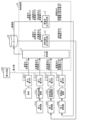
- FIG. 1 is a diagram showing an example of the configuration of an entire system including a power system and a control device for the power system according to an embodiment.
- FIG. 2 is a diagram for explaining the output of the fuel cell power generation system planned by the control device in the embodiment.
- FIG. 3 is a block diagram illustrating an example of a functional configuration of the control device according to the embodiment.
- FIG. 4 is a diagram showing an example of the generated power of the fuel cell power generation apparatus and the charging and discharging power of the storage battery apparatus controlled by the control apparatus in the embodiment.
- FIG. 5 is a flowchart illustrating an example of a processing operation of the data acquisition unit according to the embodiment.
- FIG. 6 is a flowchart illustrating an example of a processing operation of the fuel cell output calculation unit in the embodiment.
- FIG. 1 is a diagram showing an example of the configuration of an entire system including a power system and a control device for the power system according to an embodiment.
- FIG. 2 is a diagram for explaining the output of the fuel cell
- FIG. 7 is a flowchart illustrating an example of a processing operation of the storage battery output calculation unit in the embodiment.
- FIG. 8 is a flowchart illustrating an example of a processing operation of the third controller in the embodiment.
- FIG. 9 is a diagram showing an example of effects obtained by the operation modes of the control device in the embodiment.
- a method of operating a power system includes the steps of: planning an output of a fuel cell system for a second period after the first period so as to compensate for a difference between an actual value of power demand during a first period and an actual value of an output of a solar power generation system; charging a storage battery system when the fuel cell system is generating power with the planned output during the second period and the sum of the output of the solar power generation system and the output of the fuel cell system is greater than the power demand; and discharging the storage battery system to meet the power demand when the fuel cell system is generating power with the planned output during the second period and the sum of the output of the solar power generation system and the output of the fuel cell system is less than the power demand, wherein the first period is a period immediately before the second period, the second period is longer than the first period, and the planned output of the fuel cell system is constant during the second period.
- the power system includes, for example, a solar power generation system, a fuel cell system, and a storage battery system.
- the solar power generation system includes a solar power generation device
- the fuel cell system includes a fuel cell
- the storage battery system includes a storage battery.
- the power demand is, for example, the power consumption of the load of the power consumer
- the output of each of the solar power generation system and the fuel cell system is, for example, the generated power.
- the fuel cell system compensates for the difference between the power demand and the amount of photovoltaic power generation in the second period as planned by providing power as a base power source, and compensates for any temporary difference that cannot be compensated for with the power of the storage battery system, which has excellent load following capability.
- this embodiment makes it possible to mutually compensate for the above-mentioned advantages and disadvantages of the fuel cell system and the storage battery system, making it possible to meet the power demand of the load to a greater extent with the power of the power system.
- this embodiment reduces the amount of power purchased from the power grid to meet the power demand of the load.
- the deviation of the fuel cell system output due to the difference between the load power demand and the output of the photovoltaic power generation system in the second period is suppressed, compared to when the output of the fuel cell system in the second period is planned using actual values in a first period that is longer than the second period.
- the output of the fuel cell system is planned taking into account only actual values for a period closer to the second period, compared to when the output of the fuel cell system in the second period is planned using actual values in a first period that is longer than the second period.
- the output of the fuel cell system is maintained constant in the second period that is longer than the first period, deterioration of the fuel cell system can be suppressed.
- the output of the fuel cell system in the second period may be planned to be the median of the difference between the actual value of the power demand in the first period and the actual value of the output of the solar power generation system.
- the difference between each of a number of points in time within a first period is calculated, and the output of the fuel cell system in the second period is set to the median of these differences.
- the difference between the power demand and the output of the photovoltaic power generation system in the second period can be appropriately compensated for by the output of the fuel cell system.
- charging and discharging of the storage battery system can be suppressed.
- the output of the fuel cell system in the second period may be planned to be the average value of the difference between the actual value of the power demand in the first period and the actual value of the output of the solar power generation system.
- the difference between each of a number of points in time within a first period is calculated, and the output of the fuel cell system in the second period is set to the average value of these differences.
- the difference between the power demand and the output of the photovoltaic power generation system in the second period can be appropriately compensated for by the output of the fuel cell system.
- charging and discharging of the storage battery system can be suppressed.
- a control device for a power system includes a storage device that stores an actual value of the power demand during a first period and an actual value of the output of a photovoltaic power generation system, and a controller that plans an output of a fuel cell system during a second period after the first period to compensate for a difference between the actual value of the power demand during the first period and the actual value of the output of the photovoltaic power generation system, and when the fuel cell system is generating power at the planned output during the second period, if the sum of the output of the photovoltaic power generation system and the output of the fuel cell system is greater than the power demand, causes the storage battery system to charge, and when the fuel cell system is generating power at the planned output during the second period, if the sum of the output of the photovoltaic power generation system and the output of the fuel cell system is less than the power demand, causes the storage battery system to discharge so as to meet the power demand, where the first period is a period immediately before the second period, the second period
- each figure is a schematic diagram and is not necessarily a precise illustration. Furthermore, the same components are given the same reference numerals in each figure.
- Fig. 1 is a diagram showing an example of the configuration of an entire system including a power system and a control device for the power system according to the present embodiment.
- power lines are shown by solid lines
- communication lines are shown by dashed lines.
- the power system 200 in this embodiment is connected to the power grid 100 and the load 301 via power lines.
- the power system 200 supplies power to the load 301.
- the power grid 100 has a function of supplying system power and is connected to the load 301 via power lines.
- the system power is also called commercial power, and is, for example, 50 Hz or 60 Hz AC power. Therefore, when the power supplied from the power system 200 is insufficient for the power consumption of the load 301, the power grid 100 supplies the shortage of power to the load 301.
- the surplus power is taken over by the power grid 100, that is, the surplus power is sold as reverse flow power.
- the load 301 in this embodiment is composed of one or more appliances, equipment, devices, etc. that consume power.
- the power consumption of the load 301 is also called power demand.
- the load 301 is provided by power consumers such as factories and facilities.
- the power system 200 includes a solar power generation system a, a fuel cell system b, and a storage battery system c.
- the solar power generation system a includes a first controller 210, a solar power generation device 211, a first PCS (Power Conditioning System) 212, and a first power meter 213.
- PCS Power Conditioning System
- the solar power generation device 211 has, for example, one or more solar power generation units, and converts sunlight into electricity by photoelectric conversion and outputs it.
- the solar power generation unit is, for example, a solar power generation panel.
- the solar power generation device 211 is also simply referred to as a solar cell hereinafter.
- the first PCS 212 converts the power output from the solar power generation device 211 into electricity of the same quality as the grid power and outputs it.
- the first power meter 213 measures the power output from the solar power generation device 211 via the first PCS 212, i.e., the grid power, and outputs a signal indicating the measured power to the control device 10.
- the first controller 210 controls the solar power generation device 211 and the first PCS 212.
- the first controller 210 controls the solar power generation device 211 and the first PCS 212 in response to a command from the control device 10.
- Fuel cell system b includes a second controller 220, a fuel cell power generation device 221, a second PCS 222, and a second power meter 223.
- the fuel cell power generation device 221 has, for example, one or more fuel cell units, and generates electricity by chemically reacting hydrogen with oxygen.
- the hydrogen source used for power generation is, for example, a hydrogen storage tank or hydrogen infrastructure.
- the fuel cell unit is, for example, a fuel cell stack device.
- the fuel cell power generation device 221 is also simply referred to as a fuel cell hereinafter.
- the second PCS 222 converts the power output by the power generation of the fuel cell power generation device 221 into power of the same quality as the grid power and outputs it.
- the second power meter 223 measures the power output from the fuel cell power generation device 221 via the second PCS 222, i.e., the grid power, and outputs a signal indicating the measured power to the control device 10.
- the second controller 220 controls the fuel cell power generation device 221 and the second PCS 222. For example, the second controller 220 adjusts the power output from the fuel cell power generation device 221 and the second PCS 222 in response to a
- the storage battery system c includes a third controller 230, a storage battery device 231, a third PCS 232, and a third power meter 233.
- the storage battery device 231 has, for example, one or more storage battery units, and performs charging or discharging.
- the storage battery unit is, for example, a storage battery pack.
- the storage battery device 231 is also simply referred to as a storage battery hereinafter.
- the third PCS 232 converts the power output by discharging the storage battery device 231 into power of the same quality as the grid power and outputs it. Alternatively, the third PCS 232 converts the grid power and charges the storage battery device 231.
- the third power meter 233 measures the power output from the storage battery device 231 via the third PCS 232, i.e., the grid power, and outputs a signal indicating the measured power to the control device 10.
- the third power meter 233 also measures the power output from the solar power generation device 211 or the fuel cell power generation device 221 and charged to the storage battery device 231, and outputs a signal indicating the measured power to the control device 10.
- the third controller 230 controls the storage battery device 231 and the third PCS 232. For example, the third controller 230 adjusts the power discharged from the storage battery device 231 or the power charged to the storage battery device 231 in response to a command from the control device 10.
- the control device 10 in this embodiment is a control device for the power system 200, and is connected to the fourth power meter 303, the power system 200, and the database 20 via communication lines.
- the control device 10 communicates with each of the fourth power meter 303, the power system 200, and the database 20 via the communication lines.
- the power that is notified, transmitted, instructed, acquired, or received via the communication lines is not the power itself, but data indicating the magnitude of the power, such as watts.
- the fourth power meter 303 measures the power consumption of the load 301.
- Such a control device 10 receives signals indicating the power measured by each of the first power meter 213, the second power meter 223, the third power meter 233, and the fourth power meter 303 at each sampling period. The control device 10 then writes the power indicated by these signals into the database 20. Note that a specific example of the sampling period is 30 seconds or 1 minute, but is not limited to these times.
- the database 20 is a recording medium for recording power values and the like.
- the recording medium may be a hard disk drive, a RAM (Random Access Memory), a ROM (Read Only Memory), or a semiconductor memory.
- the recording medium may be either volatile or non-volatile.
- the database 20 is not provided in the control device 10, but it may be provided in the control device 10.
- FIG. 2 is a diagram for explaining the output of the fuel cell power generation device 221 planned by the control device 10. Specifically, the graph in FIG. 2 shows a schematic representation of the power at each time. The horizontal axis of the graph shows time, and the vertical axis shows power (kW).
- the control device 10 in this embodiment plans the output of the fuel cell power generation device 221 during the control period T2, i.e., the generated power FC of the fuel cell power generation device 221, at a planning point in time of, for example, "12:00".
- the control period T2 is also called the second period.
- the control period T2 is one hour from the planning point in time of "12:00” to the time of "13:00".
- the control device 10 reads out from the database 20 the power consumption D of the load 301 and the power generation PV of the photovoltaic power generation device 211 during the sampling period T1 after the planning time point. That is, the control device 10 reads out the past power consumption D of the load 301 and the past power generation PV of the photovoltaic power generation device 211 obtained for each of the above-mentioned sampling periods during the sampling period T1. Then, the control device 10 plans the power generation FC of the fuel cell power generation device 221 during the control period T2 so as to compensate for the difference between the power consumption D of the load 301 and the power generation PV of the photovoltaic power generation device 211 during the sampling period T1.
- the sampling period T1 is also called the first period.
- the sampling period T1 corresponding to the control period T2 is 15 minutes from time "11:44” to time "11:59". In this case, 15 differences are obtained during the sampling period T1.
- the sampling period T1 corresponding to the control period T2 may be 15 minutes from time "11:44:30" to time "11:59:30". In this case, 30 differences are obtained during the sampling period T1.
- control device 10 controls the fuel cell power generation device 221 and the second PCS 222 via the second controller 220 so that the planned power generation power FC of the fuel cell power generation device 221 is output during the control period T2.
- the control device 10 controls the storage battery device 231 and the third PCS 232 via the third controller 230. Specifically, when the sum of the generated power PV of the solar power generation device 211 and the generated power FC of the fuel cell power generation device 221 is greater than the power consumption D of the load 301, the control device 10 causes the storage battery device 231 to charge. On the other hand, when the sum is less than the power consumption D, the control device 10 causes the storage battery device 231 to discharge so as to satisfy the power consumption D.
- the power consumption D of the load 301 is the power measured by the fourth power meter 303.
- the power generation PV of the solar power generation device 211 is the power output from the solar power generation device 211 via the first PCS 212, and is measured by the first power meter 213. Such power generation PV of the solar power generation device 211 can also be said to be the output of the solar power generation system a or the solar power generation device 211.
- the power generation FC of the fuel cell power generation device 221 is the power output from the fuel cell power generation device 221 via the second PCS 222, and is measured by the second power meter 223.
- Such power generation FC of the fuel cell power generation device 221 can also be said to be the output of the fuel cell system b or the fuel cell power generation device 221.
- the first period which is the sampling period T1
- the second period is longer than the first period
- the planned output of the fuel cell system b is constant during the second period.
- the output of the fuel cell system b corresponds to the generated power FC of the fuel cell power generation device 221.
- the period immediately before the second period is the period from the start point to the end point described below.
- the end point is the most recent measurement point from the above-mentioned planning point among the measurement points of the multiple powers recorded in the database 20.
- the start point is the time of the sampling period T1, for example, 15 minutes, that precedes the end point.
- the first period which is the period immediately before the second period
- the start point of the first period may be after the second period that precedes the planning point, which is the start point of the second period.
- the first period may be any period that is before the start of the second period and is a period that is before the start of the second period or later than the start of the second period.
- the first period is not limited to 15 minutes, and may be 30 minutes or the like, as long as it is shorter than the second period. In other words, the first period may be a period that is 1/2 or less of the second period.
- the output of the fuel cell power generation device 221 in the control period T2 is planned based on the difference between the actual value of the past power consumption D of the load 301 and the actual value of the past power generation PV of the solar power generation device 211. Then, the fuel cell power generation device 221 outputs according to the plan. Therefore, in the operation method in this embodiment, the output of the fuel cell power generation device 221 is prioritized over the output of the storage battery device 231. Therefore, the operation method in this embodiment is also called the fuel cell priority application mode or the hydrogen priority application mode. Such an operation method is applied because when the hydrogen source of the fuel cell power generation device 221 is, for example, a hydrogen storage tank or a hydrogen infrastructure, a larger output capacity can be secured compared to the storage battery device 231.
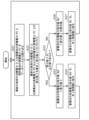
- FIG. 3 is a block diagram showing an example of the functional configuration of the control device 10. Note that in FIG. 3, the first PCS 212, the second PCS 222, and the third PCS 232 are omitted for simplicity's sake. Also, in FIG. 3, communication lines are shown with solid lines, and power lines are shown with dashed lines, for ease of understanding of the communication relationships between the components.
- the control device 10 in this embodiment includes a data acquisition unit 11, a fuel cell output calculation unit 12, and a storage battery output calculation unit 13.
- the data acquisition unit 11 acquires signals indicating the four powers from the fourth power meter 303, the first power meter 213, the second power meter 223, and the third power meter 233 for each sampling period described above. The data acquisition unit 11 then writes the numerical values of each of the four powers into the database 20 as actual values.
- the four powers are the power consumption D of the load 301, the power generated PV of the solar power generation device 211, the power generated FC of the fuel cell power generation device 221, and the discharge power Bd or charge power Bc of the storage battery device 231.
- the discharge power Bd and charge power Bc are collectively referred to as charge/discharge power SB.
- the discharge power Bd of the storage battery device 231 is the power discharged from the storage battery device 231 via the third PCS 232, and is the power measured by the third power meter 233.
- the charge power Bc of the storage battery device 231 in this embodiment is the power charged to the storage battery device 231 via the third PCS 232 from the solar power generation device 211 or the fuel cell power generation device 221, etc., and is the power measured by the third power meter 233.
- the fuel cell output calculation unit 12 reads out from the database 20 the power consumption D of the load 301 and the power generation PV of the solar power generation device 211 in the sampling period T1 immediately before the planning time. The fuel cell output calculation unit 12 then uses the power consumption D and the power generation PV to calculate the power generation FC of the fuel cell power generation device 221 in the control period T2. This allows the power generation FC to be planned.
- the fuel cell output calculation unit 12 in this embodiment plans the output of the fuel cell system b, i.e., the power generation FC, in the second period, which is the control period T2 after the first period, so as to compensate for the difference between the actual value of the power demand in the first period, which is the sampling period T1, and the actual value of the output of the solar power generation system a.
- the output of the solar power generation system a corresponds to the power generation PV of the solar power generation device 211.
- the fuel cell output calculation unit 12 instructs the second controller 220 to generate the power generation FC via a communication line.
- the second controller 220 controls the fuel cell power generation device 221 and the second PCS 222 according to instructions from the fuel cell output calculation unit 12.
- the storage battery output calculation unit 13 reads out the latest three powers from the database 20 for each storage battery command period.
- the three powers are the power consumption D of the load 301, the power generation power PV of the solar power generation device 211, and the power generation power FC of the fuel cell power generation device 221.
- a specific example of the storage battery command period is one minute.
- the storage battery output calculation unit 13 calculates the power to be discharged or charged by the storage battery device 231 based on the three read powers.
- the storage battery output calculation unit 13 commands the calculated power to the third controller 230 via a communication line.
- the storage battery output calculation unit 13 outputs a discharge power command value Bd' or a charge power command value Bc' indicating the calculated power to the third controller 230.
- the third controller 230 controls the storage battery device 231 and the third PCS 232 according to instructions from the storage battery output calculation unit 13.
- Figure 4 shows an example of the generated power FC of the fuel cell power generation system 221 and the charge/discharge power SB of the storage battery device 231 controlled by the control device 10.
- (a) of Figure 4 is a graph that shows a schematic representation of the time change in the power consumption D of the load 301 and the generated power PV of the solar power generation system 211.
- (b) of Figure 4 is a graph that shows a schematic representation of the time change in the generated power FC of the fuel cell power generation system 221.
- (c) of Figure 4 is a graph that shows a schematic representation of the time change in the charge/discharge power SB of the storage battery device 231. Note that the horizontal axis of these graphs indicates time, and the vertical axis indicates power.
- the power consumption D of the load 301 and the power generation PV of the solar power generation device 211 change between the time "00:00" and the time "24:00".
- the fuel cell output calculation unit 12 of the control device 10 plans the power generation FC of the fuel cell power generation device 221 in the control period T2 after the time ta1 at the time ta1, which is the planning time point.
- the fuel cell output calculation unit 12 calculates the power generation FC so that the power consumption D of the load 301 in the sampling period T1 is equal to the sum of the power generation PV of the solar power generation device 211 and the power generation FC of the fuel cell power generation device 221.
- This calculated power generation FC is planned as the power generation FC of the fuel cell power generation device 221 in the control period T2 after the time ta1. This makes it possible to suppress the reverse flow power and power purchases, i.e., surplus power and shortage power, in the control period T2.
- the fuel cell output calculation unit 12 repeatedly calculates the generated power FC using the control period T2 as one cycle, and commands the second controller 220 to generate the generated power FC each time the generated power FC is calculated.
- the second controller 220 controls the fuel cell power generation device 221 so that the generated power FC is generated.
- the fuel cell power generation device 221 has a rated output and a minimum output.
- the rated output is 500 kW and the minimum output is 150 kW. Therefore, when the generated power FC commanded by the fuel cell output calculation unit 12 exceeds the rated output, the second controller 220 may cause the fuel cell power generation device 221 to generate the power at the rated output. And when the generated power FC commanded by the fuel cell output calculation unit 12 falls below the minimum output, the second controller 220 may cause the fuel cell power generation device 221 to generate the power at the minimum output.
- the storage battery output calculation unit 13 calculates the charge/discharge power SB of the storage battery device 231 for each storage battery command period. At this time, the storage battery output calculation unit 13 calculates the charge/discharge power SB so that the sum of the latest power generation power PV of the photovoltaic power generation device 211, the latest power generation power FC of the fuel cell power generation device 221, and the charge/discharge power SB of the storage battery device 231 is equal to the latest power consumption D of the load 301, as shown in (e) of FIG. 4. Furthermore, the storage battery output calculation unit 13 commands the third controller 230 to discharge or charge the charge/discharge power SB.
- the storage battery output calculation unit 13 outputs the discharge power command value Bd' or the charge power command value Bc' to the third controller 230.
- the third controller 230 controls the storage battery device 231 so that the charge/discharge power SB is discharged or charged. This makes it possible to suppress instantaneous reverse flow power and power purchases during control period T2, i.e., instantaneous surplus power and power shortages.
- the storage battery output calculation unit 13 charges the storage battery system c.
- the storage battery output calculation unit 13 discharges the storage battery system c to meet the power demand.
- the charging and discharging of the storage battery system c corresponds to the charging and discharging of the storage battery device 231.
- the control device 10 in this embodiment can be said to be a device equipped with a memory and a controller.
- the memory is a recording medium that stores the power consumption D of the load 301 during the sampling period T1 and the power generation PV of the photovoltaic power generation device 211, which are read out by the fuel cell output calculation unit 12.
- the recording medium is a hard disk drive, RAM, ROM, or semiconductor memory.
- the recording medium may be volatile or non-volatile. That is, the memory stores the actual value of the power demand during the first period and the actual value of the output of the photovoltaic power generation system a.
- the controller has the functions of the fuel cell output calculation unit 12 and the storage battery output calculation unit 13.
- the controller functions as the fuel cell output calculation unit 12 to plan the output of the fuel cell system b during the second period so as to compensate for the above-mentioned difference. Furthermore, the controller functions as the above-mentioned storage battery output calculation unit 13 to charge and discharge the storage battery system c.
- the control device 10 in this embodiment may include a database 20 as described above.
- the storage device may be used as the database 20.
- each component of the control device 10 such as the data acquisition unit 11 and the controller, may be configured as dedicated hardware or circuitry. Furthermore, each component may be realized by executing a software program. That is, each component may be realized by a program execution unit such as a CPU (Central Processing Unit) or processor reading and executing a software program recorded on a recording medium such as a hard disk or semiconductor memory. Furthermore, the control device 10 may be configured with a single controller that performs centralized control, or may be configured with multiple controllers that cooperate with each other to perform distributed control.
- a program execution unit such as a CPU (Central Processing Unit) or processor reading and executing a software program recorded on a recording medium such as a hard disk or semiconductor memory.
- the control device 10 may be configured with a single controller that performs centralized control, or may be configured with multiple controllers that cooperate with each other to perform distributed control.
- FIG. 5 is a flowchart showing an example of the processing operation of the data acquisition unit 11.
- the data acquisition unit 11 executes the processes of steps S1 to S4 and S6 for each sampling period. That is, the data acquisition unit 11 acquires a signal indicating the power consumption D of the load 301 from the fourth power meter 303 (step S1). Furthermore, the data acquisition unit 11 acquires a signal indicating the power generated PV of the photovoltaic power generation device 211 from the first power meter 213 (step S2). Furthermore, the data acquisition unit 11 acquires a signal indicating the power generated FC of the fuel cell power generation device 221 from the second power meter 223 (step S3). Furthermore, the data acquisition unit 11 acquires a signal indicating the discharge power Bd or charge power Bc of the storage battery device 231 from the third power meter 233 (step S4).
- the data acquisition unit 11 writes the power consumption D of the load 301 indicated by the signal acquired in step S1 and the power of the three batteries indicated by the signals acquired in steps S2 to S4 into the database 20 (step S6).
- the power of the three batteries is the generated power PV of the solar power generation device 211, the generated power FC of the fuel cell power generation device 221, and the discharge power Bd or charge power Bc of the storage battery device 231.
- FIG. 6 is a flowchart showing an example of the processing operation of the fuel cell output calculation unit 12.
- the fuel cell output calculation unit 12 reads out from the database 20 the power consumption D of the load 301 and the power generation PV of the solar power generation device 211 for each of a number of measurement points in the sampling period T1 immediately prior to the planning point (step S11).
- the fuel cell output calculation unit 12 calculates, for each of the multiple measurement time points, the difference between the power consumption D of the load 301 and the power generation PV of the solar power generation device 211 at that measurement time point. In other words, the fuel cell output calculation unit 12 calculates the difference at each of the multiple measurement time points by subtracting the power generation PV at that measurement time point from the power consumption D at that measurement time point. The fuel cell output calculation unit 12 then calculates the median of the differences at the multiple measurement time points as difference value 1 (step S12). Note that in this embodiment, the median of the differences at the multiple measurement time points is an example of difference value 1, and difference value 1 may be the average value of these differences.
- the fuel cell output calculation unit 12 plans the output of the fuel cell system b in the second period to be the median of the difference between the actual value of the power demand in the first period and the actual value of the output of the solar power generation system a.
- the fuel cell output calculation unit 12 plans the output of the fuel cell system b in the second period to be the average of the difference between the actual value of the power demand in the first period and the actual value of the output of the solar power generation system a.
- the fuel cell output calculation unit 12 judges whether or not the difference value 1 is a positive value (step S13).
- the fuel cell output calculation unit 12 judges that the difference value 1 is a positive value (YES in step S13)
- the fuel cell output calculation unit 12 judges that the difference value 1 is not a positive value (NO in step S13)
- the generated power PV of the solar power generation device 211 is equal to or greater than the power consumption D of the load 301, and the power supplied to the load 301 is not insufficient, so the generated power FC of the fuel cell power generation device 221 is set to 0. In other words, the generated power FC is set so that the fuel cell power generation device 221 does not output.
- the fuel cell output calculation unit 12 commands the second controller 220 to generate the power FC set in step S14 or S15 (step S16).
- the second controller 220 upon receiving such a command, controls the fuel cell power generation device 221 and the second PCS 222.
- the power generation power FC set in step S14 or S15 is output from the fuel cell power generation device 221 via the second PCS 222.
- the fuel cell output calculation unit 12 determines whether or not the control period T2 has elapsed since the command in step S16 was issued (step S17). If the fuel cell output calculation unit 12 determines that the control period T2 has not elapsed (NO in step S17), it repeatedly executes the process of step S17. On the other hand, if the fuel cell output calculation unit 12 determines that the control period T2 has elapsed (YES in step S17), it repeatedly executes the process of step S11. As a result, the processes of steps S11 to S17 are repeatedly executed for each control period T2.
- FIG. 7 is a flowchart showing an example of the processing operation of the storage battery output calculation unit 13.
- the storage battery output calculation unit 13 determines whether or not the difference value 2 is a positive value (step S23). If the storage battery output calculation unit 13 determines that the difference value 2 is a positive value (YES in step S23), it sets the discharge power command value Bd' of the storage battery device 231 to the difference value 2 (step S24). Then, the storage battery output calculation unit 13 commands the third controller 230 to discharge the discharge power command value Bd' (step S25).
- the storage battery output calculation unit 13 determines that the difference value 2 is not a positive value (NO in step S23), it sets the charging power command value Bc' of the storage battery device 231 to the absolute value of the difference value 2 (step S26). Then, the storage battery output calculation unit 13 commands the third controller 230 to charge the charging power command value Bc' (step S27).
- FIG. 8 is a flowchart showing an example of the processing operation of the third controller 230. Specifically, the flowchart in FIG. 8 shows an example of the processing operation performed by the third controller 230 after the command in step S25 or S27 in the flowchart in FIG. 7 is issued.
- the third controller 230 determines whether the command, i.e., the command value, is a discharge power command value Bd' or a charge power command value Bc' (step S31).
- the third controller 230 determines that the command value is a discharge power command value Bd' (Bd' in step S31)
- the SOC of the battery device 231 is also called the battery SOC.
- the SOC lower limit is a predetermined value, and is stored in, for example, the third controller 230.
- the battery SOC being above the SOC lower limit means that the battery SOC is greater than the SOC lower limit. In other words, in step S32, it is determined whether the battery SOC is greater than the SOC lower limit.
- the third controller 230 determines whether the storage battery SOC is above the SOC lower limit (YES in step S32), it further determines whether the discharge power command value Bd' exceeds the rated output of the storage battery device 231 (step S33).
- the third controller 230 determines that the discharge power command value Bd' does not exceed the rated output (NO in step S33)
- the discharge power Bd of the storage battery device 231 is the power discharged from the storage battery device 231 via the third PCS 232. In other words, the storage battery device 231 discharges the difference value 2 via the third PCS 232.
- the third controller 230 determines that the discharge power command value Bd' exceeds the rated output (YES in step S33), it controls the storage battery device 231 and the third PCS 232 so that the discharge power Bd of the storage battery device 231 becomes the rated output (step S35). In other words, the storage battery device 231 discharges at the rated output via the third PCS 232. Also, if the third controller 230 determines that the storage battery SOC is not higher than the SOC lower limit value (NO in step S32), it controls the storage battery device 231 and the third PCS 232 so that the discharge power Bd of the storage battery device 231 becomes 0 (step S36). In other words, the storage battery device 231 does not discharge.
- step S31 when it is determined that the command value is the charge power command value Bc' (Bc' in step S31), the third controller 230 determines whether the storage battery SOC is below the SOC upper limit (step S37).
- the SOC upper limit is a predetermined value, and is stored in the third controller 230, for example.
- the storage battery SOC being below the SOC upper limit means that the storage battery SOC is smaller than the SOC upper limit.
- step S37 it is determined whether the storage battery SOC is smaller than the SOC upper limit.
- the third controller 230 determines whether the storage battery SOC is below the SOC upper limit (YES in step S37), it further determines whether the charging power command value Bc' exceeds the rated output of the storage battery device 231 (step S38).
- the third controller 230 determines that the charging power command value Bc' does not exceed the rated output (NO in step S38)
- the charging power Bc of the storage battery device 231 is the power charged to the storage battery device 231 via the third PCS 232. In other words, the storage battery device 231 charges only the absolute value of the difference value 2.
- the third controller 230 determines that the charging power command value Bc' exceeds the rated output (YES in step S38), it controls the storage battery device 231 and the third PCS 232 so that the charging power Bc of the storage battery device 231 becomes the rated output (step S40). In other words, the storage battery device 231 performs charging at the rated output. Also, if the third controller 230 determines that the storage battery SOC is not below the SOC upper limit value (NO in step S37), it controls the storage battery device 231 and the third PCS 232 so that the charging power Bc of the storage battery device 231 becomes 0 (step S41). In other words, the storage battery device 231 does not charge.
- the third controller 230 may execute each step included in the flowchart of FIG. 8 for each storage battery unit.
- the discharge power command value Bd' and the charge power command value Bc' used for each storage battery unit may be values obtained by dividing the overall command value of the storage battery device 231 by the number of storage battery units included in the storage battery device 231.
- the third controller 230 has a function of controlling the discharge power Bd and the charge power Bc of the storage battery device 231 based on the charge power command value Bc' and the discharge power command value Bd'.
- the storage battery output calculation unit 13 of the control device 10 may also have this function. In other words, the storage battery output calculation unit 13 may execute each step included in the flowchart shown in FIG. 8. In this case, the data acquisition unit 11 acquires the storage battery SOC from the third controller 230 at the same timing as the power consumption D of the load 301 and the generated power PV of the solar power generation device 211, and stores it in the database 20. Then, in step S21 of FIG.
- the storage battery output calculation unit 13 further reads out the latest storage battery SOC from the database 20, and uses the read storage battery SOC in steps S32 and S37 of FIG. 8. Meanwhile, the third controller 230 controls the storage battery device 231 and the third PCS 232 according to the discharge power Bd and the charge power Bc determined by the storage battery output calculation unit 13 in the processing of steps S34 to S36 and S39 to S41.
- FIG. 9 is a diagram showing an example of the effect obtained by the operation mode of the control device 10 in this embodiment.
- the effect obtained by the operation mode of the control device 10 is shown in comparison with the operation mode of a comparative example.
- the average value of the difference between the power consumption D of the load 301 and the power generation PV of the photovoltaic power generation device 211 is calculated for each time period in the past year. Then, this average value is planned as the power generation FC of the fuel cell power generation device 221 for that time period. For example, the average value of the above-mentioned difference is calculated for each time period of midnight, 1:00, 2:00, etc. for the past year from January 1st to December 31st. In other words, the average value of 365 points of differences is calculated for each time period. Then, for example, the average value for the midnight hours is planned as the power generation FC of the fuel cell power generation device 221 for the midnight hours from the current time onwards.
- the annual on-site self-sufficiency rate is 63.3%, and the annual grid energy rate is 36.7%.
- the on-site self-sufficiency rate is the ratio of the amount of power supplied from the power system 200 and consumed by the load 301 to the total amount of power consumed by the load 301.
- the grid energy rate is the ratio of the amount of power supplied from the power system 100 and consumed by the load 301 to the total amount of power consumed by the load 301.
- an annual on-site self-sufficiency rate of 100% can be obtained, and an annual grid power rate of 0% can be obtained.
- the on-site self-sufficiency rate of 100% and the grid energy rate of 0% are values obtained when the power system 200 has the following configuration. That is, in this configuration, the solar power generation device 211 has 1800 solar power generation panels, and the maximum output of the solar power generation device 211 as a whole is 500 kW.
- the fuel cell power generation device 221 has 100 hydrogen fuel cells, and the maximum output or rated output of the fuel cell power generation device 221 as a whole is 500 kW.
- the hydrogen fuel cell is also called a fuel cell stack device.
- the control range of the fuel cell power generation device 221 is from the rated output to 0 kW. Note that the maximum output of each hydrogen fuel cell is 5 kW.
- the control period T2 is one hour.
- the maximum output or rated output of the storage battery device 231 is 300 kW, and the capacity of the storage battery device 231 is 1000 kWh.
- the output of fuel cell system b is planned for the second period, which is the control period T2 after the first period, so as to compensate for the difference between the actual value of the power demand during the first period, which is the sampling period T1, and the actual value of the output of photovoltaic power generation system a. Furthermore, when fuel cell system b is generating power at the planned output during the second period, if the sum of the output of photovoltaic power generation system a and the output of fuel cell system b is greater than the power demand, charging is performed by storage battery system c.
- the fuel cell system b compensates for the difference between the power demand and the photovoltaic power generation during the second period, which is the control period T2, with power as a base power source as planned, and compensates for the temporary difference that cannot be compensated for with the power of the storage battery system c, which has excellent load following.
- the above-mentioned advantages and disadvantages of the fuel cell system b and the storage battery system c are mutually compensated for, and it becomes possible to meet the power demand of the load with the power of the power system 200 more.
- this embodiment reduces the purchase of power from the power grid 100 to meet the power demand of the load.
- the deviation in the output of the fuel cell system due to the difference between the load's power demand and the output of the photovoltaic power generation system a during the second period is suppressed, compared to when the output of the fuel cell system during the second period is planned using actual values during the first period that is longer than the second period.
- the output of the fuel cell system b is planned taking into account only actual values during a period closer to the second period, compared to when the output of the fuel cell system b during the second period is planned using actual values during the first period that is longer than the second period.
- the output of the fuel cell power generation device 221 during that long period is maintained constant, deterioration of the fuel cell power generation device 221 can be suppressed.
- step S12 of FIG. 6 the median of the differences is used, so in a situation where the actual value for the first period continues in the second period, the difference between the power demand in the second period and the output of the photovoltaic power generation device 211 can be appropriately compensated for by the output of the fuel cell power generation device 221. As a result, the charging and discharging of the storage battery device 231 can be suppressed.
- the difference between the power demand during the second period and the output of the photovoltaic power generation device 211 can be appropriately compensated for by the output of the fuel cell power generation device 221.
- the charging and discharging of the storage battery device 231 can be suppressed.
- control device 10 communicates with the database 20, the power system 200, and the fourth power meter 303 via communication lines, but the communication is not limited to wired communication and may be wireless communication.
- the wireless communication may be performed using Wi-Fi (registered trademark), Bluetooth (registered trademark), ZigBee (registered trademark), or a specific low-power radio.
- each component may be configured with dedicated hardware, or may be realized by executing a software program suitable for each component.
- Each component may be realized by a program execution unit such as a CPU or processor reading and executing a software program recorded on a recording medium such as a hard disk or semiconductor memory.
- the software that realizes the control device 10 and power system 200 of the above embodiment is a computer program that causes a computer to execute each step of the flowcharts shown in each of Figures 5 to 8.
- the at least one device is a computer system consisting of a microprocessor, ROM, RAM, a hard disk unit, a display unit, a keyboard, a mouse, etc.
- a computer program is stored in the RAM or hard disk unit.
- the at least one device achieves its functions by the microprocessor operating in accordance with the computer program.
- a computer program is composed of a combination of multiple instruction codes that indicate commands for a computer to achieve a specified function.
- a system LSI is an ultra-multifunctional LSI manufactured by integrating multiple components on a single chip, and specifically, is a computer system comprising a microprocessor, ROM, RAM, etc.
- a computer program is stored in the RAM. The system LSI achieves its functions when the microprocessor operates in accordance with the computer program.
- Some or all of the components constituting at least one of the above devices may be composed of an IC card or a standalone module that is detachable from the device.
- the IC card or module is a computer system composed of a microprocessor, ROM, RAM, etc.
- the IC card or module may include the above-mentioned ultra-multifunction LSI.
- the IC card or module achieves its functions when the microprocessor operates according to a computer program. This IC card or module may be tamper-resistant.
- the present disclosure may be the methods described above. It may also be a computer program that implements these methods using a computer, or a digital signal that comprises a computer program.
- the present disclosure may also be a computer program or digital signal recorded on a computer-readable recording medium, such as a flexible disk, a hard disk, a CD (Compact Disc)-ROM, a DVD, a DVD-ROM, a DVD-RAM, a BD (Blu-ray (registered trademark) Disc), a semiconductor memory, etc. It may also be a digital signal recorded on such a recording medium.
- a computer-readable recording medium such as a flexible disk, a hard disk, a CD (Compact Disc)-ROM, a DVD, a DVD-ROM, a DVD-RAM, a BD (Blu-ray (registered trademark) Disc), a semiconductor memory, etc. It may also be a digital signal recorded on such a recording medium.
- the present disclosure may also involve the transmission of computer programs or digital signals via telecommunications lines, wireless or wired communication lines, networks such as the Internet, data broadcasting, etc.
- the program or digital signal may also be implemented by another independent computer system by recording it on a recording medium and transferring it, or by transferring the program or digital signal via a network, etc.
- the power system operation method disclosed herein can be applied to devices or systems that control, for example, solar power generation systems, fuel cell systems, and battery storage systems.
- Control device 11 Data acquisition unit 12 Fuel cell output calculation unit 13 Storage battery output calculation unit 20 Database 100 Power system 200 Power system 210 First controller 211 Photovoltaic power generation device 212 First PCS 213 First power meter 220 Second controller 221 Fuel cell power generation device 222 Second PCS 223 Second power meter 230 Third controller 231 Storage battery device 232 Third PCS 233 Third power meter 301 Load 303 Fourth power meter a Photovoltaic power generation system b Fuel cell system c Storage battery system T1 Sampling period (first period) T2 Control period (second period)
Landscapes
- Engineering & Computer Science (AREA)
- Power Engineering (AREA)
- Supply And Distribution Of Alternating Current (AREA)
Abstract
The method for operating a power system (200) according to the present disclosure comprises steps of: planning the output (FC) of a fuel cell system (b) in a second period (T2) after a first period (T1) so as to compensate the difference between the actual value of a power demand amount and the actual value of the output (PV) of a solar power generation system (a) in the first period; allowing a storage battery system (c) to be charged when the sum of the outputs of the solar power generation system and the fuel cell system is greater than the power demand amount (D) when the fuel cell system generates power at an output planned in the second period; and allowing the storage battery system to discharge so as to meet the power demand amount when the sum of the outputs of the solar power generation system and the fuel cell system is smaller than the power demand amount when the fuel cell system generates power at the output planned in the second period. The first period is immediately before the second period, the second period is longer than the first period, and the planned output of the fuel cell system is constant in the second period.
Description
本開示は、電力を供給する電力システムの運転方法などに関する。
This disclosure relates to a method for operating a power system that supplies electric power.
従来、電力を供給する電力供給システムが提案されている(例えば、特許文献1参照)。この電力供給システムは、自然エネルギー発電装置である太陽光発電装置から供給される電力を調整するパワーコンディショナ装置と、蓄電池と、水素製造装置と、燃料電池とを備える。そして、電力供給システムは、施設に対して、太陽光発電装置、蓄電池および燃料電池によって得られる電力を施設に供給し、さらに、余剰電力を蓄電池または水素製造装置に供給する。また、電力供給システムは、太陽光発電装置の発電量を予測し、その予測された発電量である予測値などに基づいて、蓄電池によって充放電される電力の量と、水素製造装置に供給される電力の量と、燃料電池から供給される電力の量とを決定する。これにより、施設の需要を満たす電力を継続して供給することができる。
A power supply system that supplies electric power has been proposed in the past (see, for example, Patent Document 1). This power supply system includes a power conditioner device that adjusts the power supplied from a solar power generation device, which is a natural energy power generation device, a storage battery, a hydrogen production device, and a fuel cell. The power supply system supplies the facility with electric power obtained by the solar power generation device, the storage battery, and the fuel cell, and further supplies surplus electric power to the storage battery or the hydrogen production device. The power supply system also predicts the amount of electric power generated by the solar power generation device, and determines the amount of electric power to be charged and discharged by the storage battery, the amount of electric power to be supplied to the hydrogen production device, and the amount of electric power to be supplied from the fuel cell based on a predicted value, which is the predicted amount of electric power generation. This makes it possible to continuously supply electric power that meets the demand of the facility.
しかしながら、上記特許文献1の太陽光発電装置、蓄電池及び燃料電池を備える電力供給システム、すなわち電力システムの運転方法では、太陽発電装置の発電量の予測値を用いずに、電力供給システムが、施設の電力需要を満たす方法について検討されていない。
However, the power supply system equipped with a solar power generation device, a storage battery, and a fuel cell in the above-mentioned Patent Document 1, i.e., the power system operation method, does not consider how the power supply system can meet the power demand of the facility without using a predicted value for the amount of power generated by the solar power generation device.
そこで、本開示は、太陽光発電装置、蓄電池及び燃料電池を備える電力システムにおいて、太陽発電装置の発電量の予測値を用いずに、電力システムが、電力需要家の電力需要を満たす電力システムの運転方法などを提供する。
The present disclosure provides an operation method for a power system that includes a solar power generation device, a storage battery, and a fuel cell, and that meets the power demand of power consumers without using a predicted value for the amount of power generated by the solar power generation device.
本開示の一態様に係る電力システムの運転方法は、第1の期間における電力需要量の実績値と太陽光発電システムの出力の実績値との差分を補うように前記第1の期間より後の第2の期間における燃料電池システムの出力を計画するステップと、前記第2の期間において計画された出力で前記燃料電池システムが発電しているとき、前記太陽光発電システムの出力と前記燃料電池システムの出力の和が電力需要量よりも大きい場合、蓄電池システムに充電させるステップと、前記第2の期間において計画された出力で前記燃料電池システムが発電しているとき、前記太陽光発電システムの出力と前記燃料電池システムの出力の和が電力需要量よりも小さい場合、電力需要量を満たすように前記蓄電池システムに放電させるステップとを備え、前記第1の期間は、前記第2の期間の直前の期間であり、前記第2の期間は、前記第1の期間よりも長く、かつ前記計画された燃料電池システムの出力は前記第2の期間において一定である。
A method of operating a power system according to one aspect of the present disclosure includes the steps of: planning an output of a fuel cell system for a second period after the first period so as to compensate for a difference between an actual value of power demand during the first period and an actual value of an output of a photovoltaic power generation system; charging a storage battery system when the fuel cell system is generating power at the planned output during the second period and the sum of the output of the photovoltaic power generation system and the output of the fuel cell system is greater than the power demand; and discharging the storage battery system to meet the power demand when the fuel cell system is generating power at the planned output during the second period and the sum of the output of the photovoltaic power generation system and the output of the fuel cell system is less than the power demand, wherein the first period is a period immediately before the second period, the second period is longer than the first period, and the planned output of the fuel cell system is constant during the second period.
なお、これらの包括的または具体的な態様は、システム、方法、集積回路、コンピュータプログラムまたはコンピュータ読み取り可能なCD-ROMなどの記録媒体で実現されてもよく、システム、方法、集積回路、コンピュータプログラムおよび記録媒体の任意な組み合わせで実現されてもよい。また、記録媒体は、非一時的な記録媒体であってもよい。
These comprehensive or specific aspects may be realized by a system, a method, an integrated circuit, a computer program, or a recording medium such as a computer-readable CD-ROM, or may be realized by any combination of a system, a method, an integrated circuit, a computer program, and a recording medium. In addition, the recording medium may be a non-transitory recording medium.
本開示の電力システムの運転方法は、太陽光発電装置、蓄電池及び燃料電池を備える電力システムにおいて、太陽発電装置の発電量の予測値を用いずに、電力システムが、電力需要家の電力需要を満たすことができる。
The power system operation method disclosed herein allows a power system equipped with a solar power generation device, a storage battery, and a fuel cell to meet the power demand of power consumers without using a predicted value for the amount of power generated by the solar power generation device.
本開示の一態様における更なる利点および効果は、明細書および図面から明らかにされる。かかる利点および/または効果は、いくつかの実施の形態並びに明細書および図面に記載された構成によってそれぞれ提供されるが、その利点および効果を得るために必ずしも全ての構成が提供される必要はない。
Further advantages and benefits of certain aspects of the present disclosure will become apparent from the specification and drawings. Such advantages and/or benefits are provided by some of the embodiments and configurations described in the specification and drawings, respectively, but it is not necessary that all configurations be provided to obtain the advantages and benefits.
本開示の一態様に係る電力システムの運転方法は、第1の期間における電力需要量の実績値と太陽光発電システムの出力の実績値との差分を補うように前記第1の期間より後の第2の期間における燃料電池システムの出力を計画するステップと、前記第2の期間において計画された出力で前記燃料電池システムが発電しているとき、前記太陽光発電システムの出力と前記燃料電池システムの出力の和が電力需要量よりも大きい場合、蓄電池システムに充電させるステップと、前記第2の期間において計画された出力で前記燃料電池システムが発電しているとき、前記太陽光発電システムの出力と前記燃料電池システムの出力の和が電力需要量よりも小さい場合、電力需要量を満たすように前記蓄電池システムに放電させるステップとを備え、前記第1の期間は、前記第2の期間の直前の期間であり、前記第2の期間は、前記第1の期間よりも長く、かつ前記計画された燃料電池システムの出力は前記第2の期間において一定である。なお、電力システムは、例えば、太陽光発電システム、燃料電池システムおよび蓄電池システムを含む。太陽光発電システムは、太陽光発電装置を含み、燃料電池システムは、燃料電池を含み、蓄電池システムは、蓄電池を含む。また、電力需要量は、例えば、電力需要家が備える負荷の消費電力であって、太陽光発電システムおよび燃料電池システムのそれぞれの出力は、例えば、発電電力である。
A method of operating a power system according to one embodiment of the present disclosure includes the steps of: planning an output of a fuel cell system for a second period after the first period so as to compensate for a difference between an actual value of power demand during a first period and an actual value of an output of a solar power generation system; charging a storage battery system when the fuel cell system is generating power with the planned output during the second period and the sum of the output of the solar power generation system and the output of the fuel cell system is greater than the power demand; and discharging the storage battery system to meet the power demand when the fuel cell system is generating power with the planned output during the second period and the sum of the output of the solar power generation system and the output of the fuel cell system is less than the power demand, wherein the first period is a period immediately before the second period, the second period is longer than the first period, and the planned output of the fuel cell system is constant during the second period. The power system includes, for example, a solar power generation system, a fuel cell system, and a storage battery system. The solar power generation system includes a solar power generation device, the fuel cell system includes a fuel cell, and the storage battery system includes a storage battery. Furthermore, the power demand is, for example, the power consumption of the load of the power consumer, and the output of each of the solar power generation system and the fuel cell system is, for example, the generated power.
これにより、第1の期間における電力需要量の実績値と太陽光発電システムの出力の実績値との差分を補うように蓄電池システムの出力が計画される場合に比べ、電力システムの電力で電力需要量をより満たすことが可能になる。これは、蓄電池システムの方が燃料電池システムよりも負荷追従性に優れる一方で、燃料電池システムの方が、電力の貯蔵容量が蓄電池システムより大きいことが背景にある。この背景に鑑み、本態様では、第2の期間における電力需要量と太陽光発電量との差分に対して燃料電池システムが計画通りにベース電源として電力を補い、かつ補えきれない一時的な差分に対して負荷追従性に優れた蓄電池システムの電力でこれを補う。これにより、燃料電池システム及び蓄電池システムの上記長所と短所を互いに補う形となり、負荷の電力需要を電力システムの電力でより満たすことが可能になる。つまり、本態様により、負荷の電力需要を満たすための電力系統からの買電が低減される。
As a result, it becomes possible to meet the power demand with the power of the power system to a greater extent than when the output of the storage battery system is planned to make up for the difference between the actual value of the power demand in the first period and the actual value of the output of the photovoltaic power generation system. This is because the storage battery system has better load following capability than the fuel cell system, while the fuel cell system has a larger power storage capacity than the storage battery system. In view of this background, in this embodiment, the fuel cell system compensates for the difference between the power demand and the amount of photovoltaic power generation in the second period as planned by providing power as a base power source, and compensates for any temporary difference that cannot be compensated for with the power of the storage battery system, which has excellent load following capability. This makes it possible to mutually compensate for the above-mentioned advantages and disadvantages of the fuel cell system and the storage battery system, making it possible to meet the power demand of the load to a greater extent with the power of the power system. In other words, this embodiment reduces the amount of power purchased from the power grid to meet the power demand of the load.
また、第2の期間よりも長い第1の期間における実績値を用いて、第2の期間における燃料電池システムの出力を計画する場合に比べ、第2の期間における負荷の電力需要量と太陽光発電システムの出力との差分に対する燃料電池システムの出力のずれが抑制される。これは、第2の期間よりも長い第1の期間における実績値を用いて、第2の期間における燃料電池システムの出力を計画する場合に比べ、第2の期間により近い期間の実績値のみを考慮して燃料電池システムの出力の計画が行われることになるからである。さらに、その第1の期間よりも長い第2の期間において燃料電池システムの出力が一定に維持されるため、燃料電池システムの劣化を抑制することができる。
Furthermore, the deviation of the fuel cell system output due to the difference between the load power demand and the output of the photovoltaic power generation system in the second period is suppressed, compared to when the output of the fuel cell system in the second period is planned using actual values in a first period that is longer than the second period. This is because the output of the fuel cell system is planned taking into account only actual values for a period closer to the second period, compared to when the output of the fuel cell system in the second period is planned using actual values in a first period that is longer than the second period. Furthermore, because the output of the fuel cell system is maintained constant in the second period that is longer than the first period, deterioration of the fuel cell system can be suppressed.
また、前記第1の期間における電力需要量の実績値と前記太陽光発電システムの出力の実績値との差分の中央値となるよう前記第2の期間における前記燃料電池システムの出力を計画してもよい。
The output of the fuel cell system in the second period may be planned to be the median of the difference between the actual value of the power demand in the first period and the actual value of the output of the solar power generation system.
例えば、第1の期間内の複数の時点のそれぞれにおける差分が算出されて、第2の期間における燃料電池システムの出力が、それらの差分の中央値に設定される。これにより、第1の期間の実績値が第2の期間でも継続されるような状況では、第2の期間における電力需要量と太陽光発電システムの出力との差分を、その燃料電池システムの出力で適切に補うことができる。その結果、蓄電池システムの充放電を抑えることができる。
For example, the difference between each of a number of points in time within a first period is calculated, and the output of the fuel cell system in the second period is set to the median of these differences. In this way, in a situation where the actual value for the first period continues in the second period, the difference between the power demand and the output of the photovoltaic power generation system in the second period can be appropriately compensated for by the output of the fuel cell system. As a result, charging and discharging of the storage battery system can be suppressed.
また、前記第1の期間における電力需要量の実績値と前記太陽光発電システムの出力の実績値との差分の平均値となるよう前記第2の期間における前記燃料電池システムの出力を計画してもよい。
The output of the fuel cell system in the second period may be planned to be the average value of the difference between the actual value of the power demand in the first period and the actual value of the output of the solar power generation system.
例えば、第1の期間内の複数の時点のそれぞれにおける差分が算出されて、第2の期間における燃料電池システムの出力が、それらの差分の平均値に設定される。これにより、第1の期間の実績値が第2の期間でも継続されるような状況では、第2の期間における電力需要量と太陽光発電システムの出力との差分を、その燃料電池システムの出力で適切に補うことができる。その結果、蓄電池システムの充放電を抑えることができる。
For example, the difference between each of a number of points in time within a first period is calculated, and the output of the fuel cell system in the second period is set to the average value of these differences. In this way, in a situation where the actual value for the first period continues in the second period, the difference between the power demand and the output of the photovoltaic power generation system in the second period can be appropriately compensated for by the output of the fuel cell system. As a result, charging and discharging of the storage battery system can be suppressed.
また、本開示の一態様に係る電力システムの制御装置は、第1の期間における電力需要量の実績値と太陽光発電システムの出力の実績値を記憶する記憶器と、前記第1の期間における電力需要量の実績値と前記太陽光発電システムの出力の実績値との差分を補うように前記第1の期間より後の第2の期間における燃料電池システムの出力を計画し、前記第2の期間において計画された出力で前記燃料電池システムが発電しているとき、前記太陽光発電システムの出力と前記燃料電池システムの出力の和が電力需要量よりも大きい場合、蓄電池システムに充電させ、前記第2の期間において計画された出力で前記燃料電池システムが発電しているとき、前記太陽光発電システムの出力と前記燃料電池システムの出力の和が電力需要量よりも小さい場合、電力需要量を満たすように前記蓄電池システムに放電させる制御器とを備え、前記第1の期間は、前記第2の期間の直前の期間であり、前記第2の期間は、前記第1の期間よりも長く、かつ前記計画された燃料電池システムの出力は前記第2の期間において一定である。
In addition, a control device for a power system according to one embodiment of the present disclosure includes a storage device that stores an actual value of the power demand during a first period and an actual value of the output of a photovoltaic power generation system, and a controller that plans an output of a fuel cell system during a second period after the first period to compensate for a difference between the actual value of the power demand during the first period and the actual value of the output of the photovoltaic power generation system, and when the fuel cell system is generating power at the planned output during the second period, if the sum of the output of the photovoltaic power generation system and the output of the fuel cell system is greater than the power demand, causes the storage battery system to charge, and when the fuel cell system is generating power at the planned output during the second period, if the sum of the output of the photovoltaic power generation system and the output of the fuel cell system is less than the power demand, causes the storage battery system to discharge so as to meet the power demand, where the first period is a period immediately before the second period, the second period is longer than the first period, and the planned output of the fuel cell system is constant during the second period.
これにより、上述の電力システムの運転方法と同様の作用効果を奏することができる。
This allows the same effects to be achieved as the power system operation method described above.
以下、実施の形態について、図面を参照しながら具体的に説明する。
The following describes the embodiment in detail with reference to the drawings.
なお、以下で説明する実施の形態は、いずれも包括的または具体的な例を示すものである。以下の実施の形態で示される数値、形状、材料、構成要素、構成要素の配置位置および接続形態、ステップ、ステップの順序などは、一例であり、本開示を限定する主旨ではない。また、以下の実施の形態における構成要素のうち、最上位概念を示す独立請求項に記載されていない構成要素については、任意の構成要素として説明される。
The embodiments described below are all comprehensive or specific examples. The numerical values, shapes, materials, components, component placement and connection forms, steps, and order of steps shown in the following embodiments are merely examples and are not intended to limit the present disclosure. Furthermore, among the components in the following embodiments, components that are not described in an independent claim that indicates a superordinate concept are described as optional components.
また、各図は、模式図であり、必ずしも厳密に図示されたものではない。また、各図において、同じ構成部材については同じ符号を付している。
Furthermore, each figure is a schematic diagram and is not necessarily a precise illustration. Furthermore, the same components are given the same reference numerals in each figure.
(実施の形態)
図1は、本実施の形態における電力システムと、その電力システムの制御装置とを含む全システムの構成例を示す図である。なお、図1では、電力線は実線で示され、通信線は破線で示されている。 (Embodiment)
Fig. 1 is a diagram showing an example of the configuration of an entire system including a power system and a control device for the power system according to the present embodiment. In Fig. 1, power lines are shown by solid lines, and communication lines are shown by dashed lines.
本実施の形態における電力システム200は、電力系統100および負荷301に電力線を介して接続されている。そして、電力システム200は、負荷301に対して電力を供給する。また、電力系統100は、系統電力を供給する機能を有し、電力線を介して負荷301に接続されている。なお、系統電力は、商用電力とも呼ばれ、例えば50Hzまたは60Hzの交流電力である。したがって、負荷301の消費電力に対して、電力システム200から供給される電力が不足する場合には、電力系統100は、負荷301に対して不足分の電力を供給する。一方、負荷301の消費電力に対して、電力システム200から供給される電力が余る場合には、その余った電力は、電力系統100に引き取られる、つまり、その余った電力は逆潮流電力として売電される。なお、本実施の形態における負荷301は、電力を消費する1つ以上の機器、装置、デバイスなどからなる。また、負荷301の消費電力は、電力需要量とも呼ばれる。また、負荷301は、工場、施設等の電力需要家が備える。
The power system 200 in this embodiment is connected to the power grid 100 and the load 301 via power lines. The power system 200 supplies power to the load 301. The power grid 100 has a function of supplying system power and is connected to the load 301 via power lines. The system power is also called commercial power, and is, for example, 50 Hz or 60 Hz AC power. Therefore, when the power supplied from the power system 200 is insufficient for the power consumption of the load 301, the power grid 100 supplies the shortage of power to the load 301. On the other hand, when the power supplied from the power system 200 is surplus to the power consumption of the load 301, the surplus power is taken over by the power grid 100, that is, the surplus power is sold as reverse flow power. The load 301 in this embodiment is composed of one or more appliances, equipment, devices, etc. that consume power. The power consumption of the load 301 is also called power demand. The load 301 is provided by power consumers such as factories and facilities.
電力システム200は、太陽光発電システムa、燃料電池システムb、および蓄電池システムcを備える。太陽光発電システムaは、第1制御器210、太陽光発電装置211、第1PCS(Power Conditioning System)212、および第1電力計213を備える。
The power system 200 includes a solar power generation system a, a fuel cell system b, and a storage battery system c. The solar power generation system a includes a first controller 210, a solar power generation device 211, a first PCS (Power Conditioning System) 212, and a first power meter 213.
太陽光発電装置211は、例えば1つ以上の太陽光発電ユニットを有し、光電変換によって太陽光を電力に変換して出力する。太陽光発電ユニットは、例えば、太陽光発電パネルである。なお、太陽光発電装置211は、以下、単に、太陽電池とも呼ばれる。第1PCS212は、太陽光発電装置211から出力される電力を系統電力と同質の電力に変換して出力する。第1電力計213は、太陽光発電装置211から第1PCS212を介して出力される電力、すなわち系統電力を計測し、その計測された電力を示す信号を制御装置10に出力する。第1制御器210は、太陽光発電装置211および第1PCS212を制御する。例えば、第1制御器210は、制御装置10からの指令に応じて、太陽光発電装置211および第1PCS212を制御する。
The solar power generation device 211 has, for example, one or more solar power generation units, and converts sunlight into electricity by photoelectric conversion and outputs it. The solar power generation unit is, for example, a solar power generation panel. The solar power generation device 211 is also simply referred to as a solar cell hereinafter. The first PCS 212 converts the power output from the solar power generation device 211 into electricity of the same quality as the grid power and outputs it. The first power meter 213 measures the power output from the solar power generation device 211 via the first PCS 212, i.e., the grid power, and outputs a signal indicating the measured power to the control device 10. The first controller 210 controls the solar power generation device 211 and the first PCS 212. For example, the first controller 210 controls the solar power generation device 211 and the first PCS 212 in response to a command from the control device 10.
燃料電池システムbは、第2制御器220、燃料電池発電装置221、第2PCS222、および第2電力計223を備える。
Fuel cell system b includes a second controller 220, a fuel cell power generation device 221, a second PCS 222, and a second power meter 223.
燃料電池発電装置221は、例えば1つ以上の燃料電池ユニットを有し、水素と酸素とを化学反応させて発電する。発電に利用される水素源は、例えば、水素貯蔵器または水素インフラである。燃料電池ユニットは、例えば、燃料電池スタック装置である。なお、燃料電池発電装置221は、以下、単に、燃料電池とも呼ばれる。第2PCS222は、燃料電池発電装置221の発電によって出力される電力を系統電力と同質の電力に変換して出力する。第2電力計223は、燃料電池発電装置221から第2PCS222を介して出力される電力、すなわち系統電力を計測し、その計測された電力を示す信号を制御装置10に出力する。第2制御器220は、燃料電池発電装置221および第2PCS222を制御する。例えば、第2制御器220は、制御装置10からの指令に応じて、燃料電池発電装置221および第2PCS222から出力される電力を調整する。
The fuel cell power generation device 221 has, for example, one or more fuel cell units, and generates electricity by chemically reacting hydrogen with oxygen. The hydrogen source used for power generation is, for example, a hydrogen storage tank or hydrogen infrastructure. The fuel cell unit is, for example, a fuel cell stack device. The fuel cell power generation device 221 is also simply referred to as a fuel cell hereinafter. The second PCS 222 converts the power output by the power generation of the fuel cell power generation device 221 into power of the same quality as the grid power and outputs it. The second power meter 223 measures the power output from the fuel cell power generation device 221 via the second PCS 222, i.e., the grid power, and outputs a signal indicating the measured power to the control device 10. The second controller 220 controls the fuel cell power generation device 221 and the second PCS 222. For example, the second controller 220 adjusts the power output from the fuel cell power generation device 221 and the second PCS 222 in response to a command from the control device 10.
蓄電池システムcは、第3制御器230、蓄電池装置231、第3PCS232、および第3電力計233を備える。
The storage battery system c includes a third controller 230, a storage battery device 231, a third PCS 232, and a third power meter 233.
蓄電池装置231は、例えば1つ以上の蓄電池ユニットを有し、充電または放電を行う。蓄電池ユニットは、例えば、蓄電池パックである。なお、蓄電池装置231は、以下、単に、蓄電池とも呼ばれる。第3PCS232は、蓄電池装置231の放電によって出力される電力を系統電力と同質の電力に変換して出力する。あるいは、第3PCS232は、系統電力を変換して蓄電池装置231に充電する。第3電力計233は、蓄電池装置231から第3PCS232を介して出力される電力、すなわち系統電力を計測し、その計測された電力を示す信号を制御装置10に出力する。また、第3電力計233は、太陽光発電装置211または燃料電池発電装置221から出力され、蓄電池装置231に充電される電力を計測し、その計測された電力を示す信号を制御装置10に出力する。第3制御器230は、蓄電池装置231および第3PCS232を制御する。例えば、第3制御器230は、制御装置10からの指令に応じて、蓄電池装置231から放電される電力、または蓄電池装置231に充電される電力を調整する。
The storage battery device 231 has, for example, one or more storage battery units, and performs charging or discharging. The storage battery unit is, for example, a storage battery pack. The storage battery device 231 is also simply referred to as a storage battery hereinafter. The third PCS 232 converts the power output by discharging the storage battery device 231 into power of the same quality as the grid power and outputs it. Alternatively, the third PCS 232 converts the grid power and charges the storage battery device 231. The third power meter 233 measures the power output from the storage battery device 231 via the third PCS 232, i.e., the grid power, and outputs a signal indicating the measured power to the control device 10. The third power meter 233 also measures the power output from the solar power generation device 211 or the fuel cell power generation device 221 and charged to the storage battery device 231, and outputs a signal indicating the measured power to the control device 10. The third controller 230 controls the storage battery device 231 and the third PCS 232. For example, the third controller 230 adjusts the power discharged from the storage battery device 231 or the power charged to the storage battery device 231 in response to a command from the control device 10.
本実施の形態における制御装置10は、電力システム200の制御装置であって、第4電力計303と、電力システム200と、データベース20とのそれぞれに通信線を介して接続されている。つまり、制御装置10は、第4電力計303、電力システム200、およびデータベース20のそれぞれと、通信線を介して通信する。なお、本実施の形態において、通信線を介して通知、送信、指令、取得または受信される電力は、電力そのものではく、電力の大きさ、例えばワット数などを示すデータである。また、第4電力計303は、負荷301の消費電力を計測する。
The control device 10 in this embodiment is a control device for the power system 200, and is connected to the fourth power meter 303, the power system 200, and the database 20 via communication lines. In other words, the control device 10 communicates with each of the fourth power meter 303, the power system 200, and the database 20 via the communication lines. Note that in this embodiment, the power that is notified, transmitted, instructed, acquired, or received via the communication lines is not the power itself, but data indicating the magnitude of the power, such as watts. Also, the fourth power meter 303 measures the power consumption of the load 301.
このような制御装置10は、第1電力計213、第2電力計223、第3電力計233、および第4電力計303のそれぞれから、その電力計によって計測される電力を示す信号を、サンプリング周期ごとに受信する。そして、制御装置10は、それらの信号によって示されている電力を、データベース20に書き込む。なお、サンプリング周期の具体的な一例は、30秒または1分などであるが、これらの時間に限定されるものではない。
Such a control device 10 receives signals indicating the power measured by each of the first power meter 213, the second power meter 223, the third power meter 233, and the fourth power meter 303 at each sampling period. The control device 10 then writes the power indicated by these signals into the database 20. Note that a specific example of the sampling period is 30 seconds or 1 minute, but is not limited to these times.
データベース20は、電力の値などを記録するための記録媒体である。なお、その記録媒体は、ハードディスクドライブ、RAM(Random Access Memory)、ROM(Read Only Memory)、または半導体メモリなどである。また、その記録媒体は、揮発性であっても不揮発性であってもよい。なお、本実施の形態では、データベース20は、制御装置10に備えられていないが、制御装置10に備えられていてもよい。
The database 20 is a recording medium for recording power values and the like. The recording medium may be a hard disk drive, a RAM (Random Access Memory), a ROM (Read Only Memory), or a semiconductor memory. The recording medium may be either volatile or non-volatile. In this embodiment, the database 20 is not provided in the control device 10, but it may be provided in the control device 10.
図2は、制御装置10によって計画される燃料電池発電装置221の出力を説明するための図である。具体的には、図2のグラフは、各時刻における電力を模式的に示す。グラフの横軸は、時刻を示し、縦軸は電力(kW)を示す。
FIG. 2 is a diagram for explaining the output of the fuel cell power generation device 221 planned by the control device 10. Specifically, the graph in FIG. 2 shows a schematic representation of the power at each time. The horizontal axis of the graph shows time, and the vertical axis shows power (kW).
本実施の形態における制御装置10は、図2のグラフに示すように、例えば時刻「12:00」の計画時点において、制御期間T2における燃料電池発電装置221の出力、すなわち燃料電池発電装置221の発電電力FCを計画する。なお、制御期間T2は、第2の期間とも呼ばれる。具体的な一例では、制御期間T2は、計画時点の時刻「12:00」から時刻「13:00」までの1時間である。
As shown in the graph of FIG. 2, the control device 10 in this embodiment plans the output of the fuel cell power generation device 221 during the control period T2, i.e., the generated power FC of the fuel cell power generation device 221, at a planning point in time of, for example, "12:00". The control period T2 is also called the second period. In a specific example, the control period T2 is one hour from the planning point in time of "12:00" to the time of "13:00".
より具体的には、制御装置10は、計画時点より後のサンプリング期間T1における負荷301の消費電力Dと太陽光発電装置211の発電電力PVとを、データベース20から読み出す。つまり、制御装置10は、サンプリング期間T1において上述のサンプリング周期ごとに得られた負荷301の過去の消費電力Dと太陽光発電装置211の過去の発電電力PVとを読み出す。そして、制御装置10は、サンプリング期間T1における負荷301の消費電力Dと太陽光発電装置211の発電電力PVとの差分を補うように、制御期間T2における燃料電池発電装置221の発電電力FCを計画する。なお、サンプリング期間T1は、第1の期間とも呼ばれる。具体的な一例では、サンプリング周期が1分であるときには、制御期間T2に対応するサンプリング期間T1は、時刻「11:44」から時刻「11:59」までの15分間である。この場合、サンプリング期間T1において15個の差分が得られる。なお、サンプリング周期が30秒であるときには、制御期間T2に対応するサンプリング期間T1は、時刻「11:44:30」から時刻「11:59:30」までの15分間であってもよい。この場合、サンプリング期間T1では、30個の差分が得られる。
More specifically, the control device 10 reads out from the database 20 the power consumption D of the load 301 and the power generation PV of the photovoltaic power generation device 211 during the sampling period T1 after the planning time point. That is, the control device 10 reads out the past power consumption D of the load 301 and the past power generation PV of the photovoltaic power generation device 211 obtained for each of the above-mentioned sampling periods during the sampling period T1. Then, the control device 10 plans the power generation FC of the fuel cell power generation device 221 during the control period T2 so as to compensate for the difference between the power consumption D of the load 301 and the power generation PV of the photovoltaic power generation device 211 during the sampling period T1. The sampling period T1 is also called the first period. In a specific example, when the sampling period is 1 minute, the sampling period T1 corresponding to the control period T2 is 15 minutes from time "11:44" to time "11:59". In this case, 15 differences are obtained during the sampling period T1. When the sampling period is 30 seconds, the sampling period T1 corresponding to the control period T2 may be 15 minutes from time "11:44:30" to time "11:59:30". In this case, 30 differences are obtained during the sampling period T1.
そして、制御装置10は、その計画された燃料電池発電装置221の発電電力FCが制御期間T2において出力されるように、第2制御器220を介して燃料電池発電装置221および第2PCS222を制御する。
Then, the control device 10 controls the fuel cell power generation device 221 and the second PCS 222 via the second controller 220 so that the planned power generation power FC of the fuel cell power generation device 221 is output during the control period T2.
さらに、制御装置10は、燃料電池発電装置221が制御期間T2において計画された発電電力FCを発電しているときには、第3制御器230を介して蓄電池装置231および第3PCS232を制御する。具体的には、制御装置10は、太陽光発電装置211の発電電力PVと燃料電池発電装置221の発電電力FCの和が、負荷301の消費電力Dよりも大きい場合、蓄電池装置231に充電させる。一方、制御装置10は、その和が消費電力Dよりも小さい場合、消費電力Dを満たすように蓄電池装置231に放電させる。
Furthermore, when the fuel cell power generation device 221 is generating the planned generated power FC during the control period T2, the control device 10 controls the storage battery device 231 and the third PCS 232 via the third controller 230. Specifically, when the sum of the generated power PV of the solar power generation device 211 and the generated power FC of the fuel cell power generation device 221 is greater than the power consumption D of the load 301, the control device 10 causes the storage battery device 231 to charge. On the other hand, when the sum is less than the power consumption D, the control device 10 causes the storage battery device 231 to discharge so as to satisfy the power consumption D.
なお、負荷301の消費電力Dは、第4電力計303によって計測される電力である。また、太陽光発電装置211の発電電力PVは、太陽光発電装置211から第1PCS212を介して出力される電力であって、第1電力計213によって計測される。このような太陽光発電装置211の発電電力PVは、太陽光発電システムaまたは太陽光発電装置211の出力であるとも言える。同様に、燃料電池発電装置221の発電電力FCは、燃料電池発電装置221から第2PCS222を介して出力される電力であって、第2電力計223によって計測される電力である。このような燃料電池発電装置221の発電電力FCは、燃料電池システムbまたは燃料電池発電装置221の出力であるとも言える。
The power consumption D of the load 301 is the power measured by the fourth power meter 303. The power generation PV of the solar power generation device 211 is the power output from the solar power generation device 211 via the first PCS 212, and is measured by the first power meter 213. Such power generation PV of the solar power generation device 211 can also be said to be the output of the solar power generation system a or the solar power generation device 211. Similarly, the power generation FC of the fuel cell power generation device 221 is the power output from the fuel cell power generation device 221 via the second PCS 222, and is measured by the second power meter 223. Such power generation FC of the fuel cell power generation device 221 can also be said to be the output of the fuel cell system b or the fuel cell power generation device 221.
このように、本実施の形態では、サンプリング期間T1である第1の期間は、制御期間T2である第2の期間の直前の期間である。また、第2の期間は、第1の期間よりも長く、かつ計画する燃料電池システムbの出力は第2の期間において一定である。なお、燃料電池システムbの出力は、燃料電池発電装置221の発電電力FCに相当する。ここで、第2の期間の直前の期間とは、本実施の形態では、下記の開始時点から終了時点までの期間である。つまり、その終了時点は、データベース20に記録されている複数の電力のそれぞれの計測時点のうち、上述の計画時点から見て最近の計測時点である。そして、開始時点は、その終了時点からサンプリング期間T1の時間、例えば15分だけ遡った時点である。しかし、その第2の期間の直前の期間である第1の期間は、一例であって、本実施の形態に限定されない。例えば、第1の期間の開始時点は、第2の期間の開始時点である計画時点から第2の期間だけ遡った時点以降であってもよい。第1の期間は、換言すれば、第2の期間の開始時点よりも前で、かつ第2の期間の開始時点よりも第2の期間前以降の期間であれば、任意でよい。また、第1の期間は、第2の期間よりも短ければ、15分に限らず、30分などであってもよい。換言すれば、第1の期間は、第2の期間の1/2以下の期間であってもよい。
In this way, in this embodiment, the first period, which is the sampling period T1, is the period immediately before the second period, which is the control period T2. The second period is longer than the first period, and the planned output of the fuel cell system b is constant during the second period. The output of the fuel cell system b corresponds to the generated power FC of the fuel cell power generation device 221. Here, in this embodiment, the period immediately before the second period is the period from the start point to the end point described below. In other words, the end point is the most recent measurement point from the above-mentioned planning point among the measurement points of the multiple powers recorded in the database 20. The start point is the time of the sampling period T1, for example, 15 minutes, that precedes the end point. However, the first period, which is the period immediately before the second period, is just an example and is not limited to this embodiment. For example, the start point of the first period may be after the second period that precedes the planning point, which is the start point of the second period. In other words, the first period may be any period that is before the start of the second period and is a period that is before the start of the second period or later than the start of the second period. Also, the first period is not limited to 15 minutes, and may be 30 minutes or the like, as long as it is shorter than the second period. In other words, the first period may be a period that is 1/2 or less of the second period.
また、本実施の形態における制御装置10による電力システム200の運転方法では、上述のように、負荷301の過去の消費電力Dである実績値と、太陽光発電装置211の過去の発電電力PVである実績値との差分に基づいて、制御期間T2における燃料電池発電装置221の出力が計画される。そして、その計画どおりに燃料電池発電装置221が出力する。したがって、本実施の形態における運転方法では、燃料電池発電装置221の出力の方が蓄電池装置231の出力よりも優先される。そのため、本実施の形態における運転方法は、燃料電池優先適用モードまたは水素優先適用モードとも呼ばれる。このような運転方法が適用されるのは、燃料電池発電装置221の水素源が、例えば、水素貯蔵器または水素インフラであるとき、蓄電池装置231に比べ大きな出力容量が確保可能であるからである。
Furthermore, in the operation method of the power system 200 by the control device 10 in this embodiment, as described above, the output of the fuel cell power generation device 221 in the control period T2 is planned based on the difference between the actual value of the past power consumption D of the load 301 and the actual value of the past power generation PV of the solar power generation device 211. Then, the fuel cell power generation device 221 outputs according to the plan. Therefore, in the operation method in this embodiment, the output of the fuel cell power generation device 221 is prioritized over the output of the storage battery device 231. Therefore, the operation method in this embodiment is also called the fuel cell priority application mode or the hydrogen priority application mode. Such an operation method is applied because when the hydrogen source of the fuel cell power generation device 221 is, for example, a hydrogen storage tank or a hydrogen infrastructure, a larger output capacity can be secured compared to the storage battery device 231.
図3は、制御装置10の機能構成の一例を示すブロック図である。なお、図3では、説明を簡単にするために、第1PCS212、第2PCS222、および第3PCS232は、省略されている。また、図3では、各構成要素間の通信関係を分かり易くするために、通信線が実線で示され、電力線は破線で示されている。
FIG. 3 is a block diagram showing an example of the functional configuration of the control device 10. Note that in FIG. 3, the first PCS 212, the second PCS 222, and the third PCS 232 are omitted for simplicity's sake. Also, in FIG. 3, communication lines are shown with solid lines, and power lines are shown with dashed lines, for ease of understanding of the communication relationships between the components.
本実施の形態における制御装置10は、データ取得部11と、燃料電池出力算出部12と、蓄電池出力算出部13とを備える。
The control device 10 in this embodiment includes a data acquisition unit 11, a fuel cell output calculation unit 12, and a storage battery output calculation unit 13.
データ取得部11は、第4電力計303、第1電力計213、第2電力計223、および第3電力計233から4つの電力を示す信号を、上述のサンプリング周期ごとに取得する。そして、データ取得部11は、その4つの電力のそれぞれの数値を実績値としてデータベース20に書き込む。4つの電力は、負荷301の消費電力Dと、太陽光発電装置211の発電電力PVと、燃料電池発電装置221の発電電力FCと、蓄電池装置231の放電電力Bdまたは充電電力Bcである。その放電電力Bdおよび充電電力Bcは、充放電電力SBと総称される。
The data acquisition unit 11 acquires signals indicating the four powers from the fourth power meter 303, the first power meter 213, the second power meter 223, and the third power meter 233 for each sampling period described above. The data acquisition unit 11 then writes the numerical values of each of the four powers into the database 20 as actual values. The four powers are the power consumption D of the load 301, the power generated PV of the solar power generation device 211, the power generated FC of the fuel cell power generation device 221, and the discharge power Bd or charge power Bc of the storage battery device 231. The discharge power Bd and charge power Bc are collectively referred to as charge/discharge power SB.
なお、本実施の形態における蓄電池装置231の放電電力Bdは、蓄電池装置231から第3PCS232を介して放電される電力であって、第3電力計233によって計測される電力である。同様に、本実施の形態における蓄電池装置231の充電電力Bcは、太陽光発電装置211または燃料電池発電装置221などから第3PCS232を介して蓄電池装置231に充電される電力であって、第3電力計233によって計測される電力である。
In this embodiment, the discharge power Bd of the storage battery device 231 is the power discharged from the storage battery device 231 via the third PCS 232, and is the power measured by the third power meter 233. Similarly, the charge power Bc of the storage battery device 231 in this embodiment is the power charged to the storage battery device 231 via the third PCS 232 from the solar power generation device 211 or the fuel cell power generation device 221, etc., and is the power measured by the third power meter 233.
燃料電池出力算出部12は、計画時点の直近にあるサンプリング期間T1における負荷301の消費電力Dと、太陽光発電装置211の発電電力PVとをデータベース20から読み出す。そして、燃料電池出力算出部12は、その消費電力Dおよび発電電力PVを用いて、制御期間T2における燃料電池発電装置221の発電電力FCを算出する。これにより、発電電力FCが計画される。つまり、本実施の形態における燃料電池出力算出部12は、サンプリング期間T1である第1の期間における電力需要量の実績値と太陽光発電システムaの出力の実績値との差分を補うようにその第1の期間より後の制御期間T2である第2の期間における燃料電池システムbの出力、すなわち発電電力FCを計画する。なお、太陽光発電システムaの出力は、太陽光発電装置211の発電電力PVに相当する。燃料電池出力算出部12は、その発電電力FCの発電を第2制御器220に通信線を介して指令する。第2制御器220は、その燃料電池出力算出部12からの指令にしたがって、燃料電池発電装置221および第2PCS222を制御する。
The fuel cell output calculation unit 12 reads out from the database 20 the power consumption D of the load 301 and the power generation PV of the solar power generation device 211 in the sampling period T1 immediately before the planning time. The fuel cell output calculation unit 12 then uses the power consumption D and the power generation PV to calculate the power generation FC of the fuel cell power generation device 221 in the control period T2. This allows the power generation FC to be planned. In other words, the fuel cell output calculation unit 12 in this embodiment plans the output of the fuel cell system b, i.e., the power generation FC, in the second period, which is the control period T2 after the first period, so as to compensate for the difference between the actual value of the power demand in the first period, which is the sampling period T1, and the actual value of the output of the solar power generation system a. The output of the solar power generation system a corresponds to the power generation PV of the solar power generation device 211. The fuel cell output calculation unit 12 instructs the second controller 220 to generate the power generation FC via a communication line. The second controller 220 controls the fuel cell power generation device 221 and the second PCS 222 according to instructions from the fuel cell output calculation unit 12.
蓄電池出力算出部13は、上述の制御期間T2において計画された発電電力FCを燃料電池発電装置221が発電しているときには、蓄電池指令周期ごとに、最新の3つの電力をデータベース20から読み出す。3つの電力は、負荷301の消費電力D、太陽光発電装置211の発電電力PV、および燃料電池発電装置221の発電電力FCである。なお、蓄電池指令周期の具体的な一例は、1分である。そして、蓄電池出力算出部13は、その読み出された3つの電力に基づいて、蓄電池装置231が放電または充電すべき電力を算出する。蓄電池出力算出部13は、その算出された電力を第3制御器230に通信線を介して指令する。つまり、蓄電池出力算出部13は、その算出された電力を示す放電電力指令値Bd’または充電電力指令値Bc’を、第3制御器230に出力する。第3制御器230は、その蓄電池出力算出部13からの指令にしたがって、蓄電池装置231および第3PCS232を制御する。
When the fuel cell power generation device 221 is generating the planned power generation power FC in the above-mentioned control period T2, the storage battery output calculation unit 13 reads out the latest three powers from the database 20 for each storage battery command period. The three powers are the power consumption D of the load 301, the power generation power PV of the solar power generation device 211, and the power generation power FC of the fuel cell power generation device 221. A specific example of the storage battery command period is one minute. Then, the storage battery output calculation unit 13 calculates the power to be discharged or charged by the storage battery device 231 based on the three read powers. The storage battery output calculation unit 13 commands the calculated power to the third controller 230 via a communication line. In other words, the storage battery output calculation unit 13 outputs a discharge power command value Bd' or a charge power command value Bc' indicating the calculated power to the third controller 230. The third controller 230 controls the storage battery device 231 and the third PCS 232 according to instructions from the storage battery output calculation unit 13.
図4は、制御装置10によって制御される燃料電池発電装置221の発電電力FCおよび蓄電池装置231の充放電電力SBの一例を示す図である。図4の(a)は、負荷301の消費電力Dと、太陽光発電装置211の発電電力PVとの時間変化を模式的に示すグラフである。図4の(b)は、燃料電池発電装置221の発電電力FCの時間変化を模式的に示すグラフである。図4の(c)は、蓄電池装置231の充放電電力SBの時間変化を模式的に示すグラフである。なお、これらのグラフの横軸は時刻を示し、縦軸は電力を示す。
Figure 4 shows an example of the generated power FC of the fuel cell power generation system 221 and the charge/discharge power SB of the storage battery device 231 controlled by the control device 10. (a) of Figure 4 is a graph that shows a schematic representation of the time change in the power consumption D of the load 301 and the generated power PV of the solar power generation system 211. (b) of Figure 4 is a graph that shows a schematic representation of the time change in the generated power FC of the fuel cell power generation system 221. (c) of Figure 4 is a graph that shows a schematic representation of the time change in the charge/discharge power SB of the storage battery device 231. Note that the horizontal axis of these graphs indicates time, and the vertical axis indicates power.
例えば、負荷301の消費電力Dと、太陽光発電装置211の発電電力PVとは、図4の(a)に示すように、時刻「00:00」から時刻「24:00」までの間で変化する。ここで、制御装置10の燃料電池出力算出部12は、計画時点である時刻ta1に、時刻ta1以降の制御期間T2における燃料電池発電装置221の発電電力FCを計画する。このとき、燃料電池出力算出部12は、図4の(d)に示すように、サンプリング期間T1における負荷301の消費電力Dが、太陽光発電装置211の発電電力PVと、燃料電池発電装置221の発電電力FCとの和に等しくなるように、その発電電力FCを算出する。この算出された発電電力FCが、時刻ta1以降の制御期間T2における燃料電池発電装置221の発電電力FCとして計画される。これにより、制御期間T2における逆潮流電力および買電、すなわち余剰電力および不足電力を抑制することができる。
For example, as shown in FIG. 4A, the power consumption D of the load 301 and the power generation PV of the solar power generation device 211 change between the time "00:00" and the time "24:00". Here, the fuel cell output calculation unit 12 of the control device 10 plans the power generation FC of the fuel cell power generation device 221 in the control period T2 after the time ta1 at the time ta1, which is the planning time point. At this time, as shown in FIG. 4D, the fuel cell output calculation unit 12 calculates the power generation FC so that the power consumption D of the load 301 in the sampling period T1 is equal to the sum of the power generation PV of the solar power generation device 211 and the power generation FC of the fuel cell power generation device 221. This calculated power generation FC is planned as the power generation FC of the fuel cell power generation device 221 in the control period T2 after the time ta1. This makes it possible to suppress the reverse flow power and power purchases, i.e., surplus power and shortage power, in the control period T2.
燃料電池出力算出部12は、このような発電電力FCの算出を、制御期間T2を一周期として用いて繰り返し実行し、発電電力FCが算出されるごとに、その発電電力FCの発電を第2制御器220に指令する。その結果、図4の(b)に示すように、第2制御器220は、発電電力FCが発電されるように燃料電池発電装置221を制御する。ここで、燃料電池発電装置221には、定格出力と最低出力とがある。例えば、定格出力は500kWであり、最低出力は150kWである。したがって、第2制御器220は、燃料電池出力算出部12から指令された発電電力FCが定格出力を超える場合には、その定格出力の発電を燃料電池発電装置221に実行させてもよい。そして、第2制御器220は、燃料電池出力算出部12から指令された発電電力FCが最低出力を下回る場合には、その最低出力の発電を燃料電池発電装置221に実行させてもよい。
The fuel cell output calculation unit 12 repeatedly calculates the generated power FC using the control period T2 as one cycle, and commands the second controller 220 to generate the generated power FC each time the generated power FC is calculated. As a result, as shown in FIG. 4B, the second controller 220 controls the fuel cell power generation device 221 so that the generated power FC is generated. Here, the fuel cell power generation device 221 has a rated output and a minimum output. For example, the rated output is 500 kW and the minimum output is 150 kW. Therefore, when the generated power FC commanded by the fuel cell output calculation unit 12 exceeds the rated output, the second controller 220 may cause the fuel cell power generation device 221 to generate the power at the rated output. And when the generated power FC commanded by the fuel cell output calculation unit 12 falls below the minimum output, the second controller 220 may cause the fuel cell power generation device 221 to generate the power at the minimum output.
そして、蓄電池出力算出部13は、上述の蓄電池指令周期ごとに、蓄電池装置231の充放電電力SBを算出する。このとき、蓄電池出力算出部13は、図4の(e)に示すように、太陽光発電装置211の最新の発電電力PVと、燃料電池発電装置221の最新の発電電力FCと、蓄電池装置231の充放電電力SBとの和が、最新の負荷301の消費電力Dに等しくなるように、その充放電電力SBを算出する。さらに、蓄電池出力算出部13は、その充放電電力SBの放電または充電を第3制御器230に指令する。つまり、蓄電池出力算出部13は、放電電力指令値Bd’または充電電力指令値Bc’を第3制御器230に出力する。その結果、図4の(c)に示すように、第3制御器230は、充放電電力SBの放電または充電が行われるように蓄電池装置231を制御する。これにより、制御期間T2における瞬時の逆潮流電力および買電、すなわち瞬時の余剰電力および不足電力を抑制することができる。
Then, the storage battery output calculation unit 13 calculates the charge/discharge power SB of the storage battery device 231 for each storage battery command period. At this time, the storage battery output calculation unit 13 calculates the charge/discharge power SB so that the sum of the latest power generation power PV of the photovoltaic power generation device 211, the latest power generation power FC of the fuel cell power generation device 221, and the charge/discharge power SB of the storage battery device 231 is equal to the latest power consumption D of the load 301, as shown in (e) of FIG. 4. Furthermore, the storage battery output calculation unit 13 commands the third controller 230 to discharge or charge the charge/discharge power SB. In other words, the storage battery output calculation unit 13 outputs the discharge power command value Bd' or the charge power command value Bc' to the third controller 230. As a result, as shown in (c) of FIG. 4, the third controller 230 controls the storage battery device 231 so that the charge/discharge power SB is discharged or charged. This makes it possible to suppress instantaneous reverse flow power and power purchases during control period T2, i.e., instantaneous surplus power and power shortages.
つまり、本実施の形態における蓄電池出力算出部13は、制御期間T2である第2の期間において計画された出力で燃料電池システムbが発電しているとき、太陽光発電システムaの出力と燃料電池システムbの出力の和が電力需要量よりも大きい場合、蓄電池システムcに充電させる。一方、蓄電池出力算出部13は、制御期間T2である第2の期間において計画された出力で燃料電池システムbが発電しているとき、太陽光発電システムaの出力と燃料電池システムbの出力の和が電力需要量よりも小さい場合、電力需要量を満たすように蓄電池システムcに放電させる。なお、蓄電池システムcの充電および放電は、蓄電池装置231の充電および放電に相当する。
In other words, in this embodiment, when fuel cell system b is generating power at the planned output during the second period, which is control period T2, if the sum of the output of photovoltaic power generation system a and the output of fuel cell system b is greater than the power demand, the storage battery output calculation unit 13 charges the storage battery system c. On the other hand, when fuel cell system b is generating power at the planned output during the second period, which is control period T2, if the sum of the output of photovoltaic power generation system a and the output of fuel cell system b is less than the power demand, the storage battery output calculation unit 13 discharges the storage battery system c to meet the power demand. The charging and discharging of the storage battery system c corresponds to the charging and discharging of the storage battery device 231.
なお、図4における時刻ta2から時刻ta3までの期間では、太陽光発電装置211の発電電力PVが大きいにもかかわらず、燃料電池発電装置221の発電電力FCを最低出力よりも下げることができない。そのため、発電電力PVの余剰分が大きな充電電力Bcとして蓄電池装置231に充電される。一方、時刻ta4から時刻ta5までの期間では、太陽光発電装置211の発電電力PVが小さいにもかかわらず、燃料電池発電装置221の発電電力FCを定格出力よりも上げることができない。そのため、発電電力PVまたは発電電力FCの不足分が大きな放電電力Bdとして蓄電池装置231から放電される。
Note that in the period from time ta2 to time ta3 in FIG. 4, even though the generated power PV of the solar power generation device 211 is large, the generated power FC of the fuel cell power generation device 221 cannot be reduced below the minimum output. Therefore, the surplus of the generated power PV is charged to the storage battery device 231 as a large charging power Bc. On the other hand, in the period from time ta4 to time ta5, even though the generated power PV of the solar power generation device 211 is small, the generated power FC of the fuel cell power generation device 221 cannot be increased above the rated output. Therefore, the shortfall in the generated power PV or generated power FC is discharged from the storage battery device 231 as a large discharge power Bd.
このような本実施の形態における制御装置10は、記憶器と制御器とを備える装置であると言える。記憶器は、燃料電池出力算出部12によって読み出された、サンプリング期間T1における負荷301の消費電力Dと、太陽光発電装置211の発電電力PVとを記憶する記録媒体である。なお、その記録媒体は、ハードディスクドライブ、RAM、ROM、または半導体メモリなどである。また、その記録媒体は、揮発性であっても不揮発性であってもよい。つまり、記憶器は、第1の期間における電力需要量の実績値と太陽光発電システムaの出力の実績値を記憶する。また、制御器は、燃料電池出力算出部12と蓄電池出力算出部13とのそれぞれの機能を有する。つまり、制御器は、燃料電池出力算出部12として機能することによって、上述の差分を補うように第2の期間における燃料電池システムbの出力を計画する。さらに、制御器は、上述の蓄電池出力算出部13として機能することによって、蓄電池システムcに充電および放電させる。
The control device 10 in this embodiment can be said to be a device equipped with a memory and a controller. The memory is a recording medium that stores the power consumption D of the load 301 during the sampling period T1 and the power generation PV of the photovoltaic power generation device 211, which are read out by the fuel cell output calculation unit 12. The recording medium is a hard disk drive, RAM, ROM, or semiconductor memory. The recording medium may be volatile or non-volatile. That is, the memory stores the actual value of the power demand during the first period and the actual value of the output of the photovoltaic power generation system a. The controller has the functions of the fuel cell output calculation unit 12 and the storage battery output calculation unit 13. That is, the controller functions as the fuel cell output calculation unit 12 to plan the output of the fuel cell system b during the second period so as to compensate for the above-mentioned difference. Furthermore, the controller functions as the above-mentioned storage battery output calculation unit 13 to charge and discharge the storage battery system c.
なお、本実施の形態における制御装置10は、上述のようにデータベース20を備えていてもよい。この場合、記憶器は、データベース20として用いられてもよい。
The control device 10 in this embodiment may include a database 20 as described above. In this case, the storage device may be used as the database 20.
また、制御装置10に備えられるデータ取得部11および制御器などの各構成要素は、専用のハードウェアまたは回路として構成されていてもよい。また、各構成要素は、ソフトウェアプログラムを実行することによって実現されてもよい。つまり、各構成要素は、CPU(Central Processing Unit)またはプロセッサなどのプログラム実行部が、ハードディスクまたは半導体メモリなどの記録媒体に記録されたソフトウェアプログラムを読み出して実行することによって実現されてもよい。また、制御装置10は、集中制御を行う単独の制御器で構成されていてもよく、互いに協働して分散制御を行う複数の制御器で構成されていてもよい。
Furthermore, each component of the control device 10, such as the data acquisition unit 11 and the controller, may be configured as dedicated hardware or circuitry. Furthermore, each component may be realized by executing a software program. That is, each component may be realized by a program execution unit such as a CPU (Central Processing Unit) or processor reading and executing a software program recorded on a recording medium such as a hard disk or semiconductor memory. Furthermore, the control device 10 may be configured with a single controller that performs centralized control, or may be configured with multiple controllers that cooperate with each other to perform distributed control.
図5は、データ取得部11の処理動作の一例を示すフローチャートである。
FIG. 5 is a flowchart showing an example of the processing operation of the data acquisition unit 11.
データ取得部11は、サンプリング周期ごとに、ステップS1~S4およびS6の処理を実行する。つまり、データ取得部11は、第4電力計303から負荷301の消費電力Dを示す信号を取得する(ステップS1)。さらに、データ取得部11は、第1電力計213から太陽光発電装置211の発電電力PVを示す信号を取得する(ステップS2)。さらに、データ取得部11は、第2電力計223から燃料電池発電装置221の発電電力FCを示す信号を取得する(ステップS3)。さらに、データ取得部11は、第3電力計233から蓄電池装置231の放電電力Bdまたは充電電力Bcを示す信号を取得する(ステップS4)。
The data acquisition unit 11 executes the processes of steps S1 to S4 and S6 for each sampling period. That is, the data acquisition unit 11 acquires a signal indicating the power consumption D of the load 301 from the fourth power meter 303 (step S1). Furthermore, the data acquisition unit 11 acquires a signal indicating the power generated PV of the photovoltaic power generation device 211 from the first power meter 213 (step S2). Furthermore, the data acquisition unit 11 acquires a signal indicating the power generated FC of the fuel cell power generation device 221 from the second power meter 223 (step S3). Furthermore, the data acquisition unit 11 acquires a signal indicating the discharge power Bd or charge power Bc of the storage battery device 231 from the third power meter 233 (step S4).
次に、データ取得部11は、ステップS1で取得された信号によって示される負荷301の消費電力Dと、ステップS2~S4において取得された信号によって示される3電池の電力とをデータベース20に書き込む(ステップS6)。なお、3電池の電力は、太陽光発電装置211の発電電力PVと、燃料電池発電装置221の発電電力FCと、蓄電池装置231の放電電力Bdまたは充電電力Bcとである。
Next, the data acquisition unit 11 writes the power consumption D of the load 301 indicated by the signal acquired in step S1 and the power of the three batteries indicated by the signals acquired in steps S2 to S4 into the database 20 (step S6). The power of the three batteries is the generated power PV of the solar power generation device 211, the generated power FC of the fuel cell power generation device 221, and the discharge power Bd or charge power Bc of the storage battery device 231.
図6は、燃料電池出力算出部12の処理動作の一例を示すフローチャートである。
FIG. 6 is a flowchart showing an example of the processing operation of the fuel cell output calculation unit 12.
燃料電池出力算出部12は、計画時点の直近のサンプリング期間T1内における複数の計測時点のそれぞれの、負荷301の消費電力Dと、太陽光発電装置211の発電電力PVとを、データベース20から読み出す(ステップS11)。
The fuel cell output calculation unit 12 reads out from the database 20 the power consumption D of the load 301 and the power generation PV of the solar power generation device 211 for each of a number of measurement points in the sampling period T1 immediately prior to the planning point (step S11).
次に、燃料電池出力算出部12は、その複数の計測時点のそれぞれについて、その計測時点における負荷301の消費電力Dと太陽光発電装置211の発電電力PVとの差分を算出する。つまり、燃料電池出力算出部12は、複数の計測時点のそれぞれで、その計測時点における消費電力Dから、その計測時点における発電電力PVを減算することによって、その計測時点における差分を算出する。そして、燃料電池出力算出部12は、複数の計測時点のそれぞれの差分の中央値を差分値1として算出する(ステップS12)。なお、本実施の形態では、複数の計測時点のそれぞれの差分の中央値は、差分値1の一例であって、差分値1は、それらの差分の平均値であってもよい。
Next, the fuel cell output calculation unit 12 calculates, for each of the multiple measurement time points, the difference between the power consumption D of the load 301 and the power generation PV of the solar power generation device 211 at that measurement time point. In other words, the fuel cell output calculation unit 12 calculates the difference at each of the multiple measurement time points by subtracting the power generation PV at that measurement time point from the power consumption D at that measurement time point. The fuel cell output calculation unit 12 then calculates the median of the differences at the multiple measurement time points as difference value 1 (step S12). Note that in this embodiment, the median of the differences at the multiple measurement time points is an example of difference value 1, and difference value 1 may be the average value of these differences.
つまり、本実施の形態における燃料電池出力算出部12は、第1の期間における電力需要量の実績値と太陽光発電システムaの出力の実績値との差分の中央値となるよう第2の期間における燃料電池システムbの出力を計画する。または、燃料電池出力算出部12は、第1の期間における電力需要量の実績値と太陽光発電システムaの出力の実績値との差分の平均値となるよう第2の期間における燃料電池システムbの出力を計画する。
In other words, in this embodiment, the fuel cell output calculation unit 12 plans the output of the fuel cell system b in the second period to be the median of the difference between the actual value of the power demand in the first period and the actual value of the output of the solar power generation system a. Alternatively, the fuel cell output calculation unit 12 plans the output of the fuel cell system b in the second period to be the average of the difference between the actual value of the power demand in the first period and the actual value of the output of the solar power generation system a.
そして、燃料電池出力算出部12は、差分値1が正の値であるか否かを判定する(ステップS13)。ここで、燃料電池出力算出部12は、差分値1が正の値であると判定すると(ステップS13のYES)、燃料電池発電装置221の発電電力FCを差分値1に設定する(ステップS14)。一方、燃料電池出力算出部12は、差分値1が正の値でないと判定すると(ステップS13のNO)、燃料電池発電装置221の発電電力FCを0に設定する(ステップS15)。つまり、差分値1が正の値でないときには、太陽光発電装置211の発電電力PVは、負荷301の消費電力D以上であって、負荷301への供給電力は不足していないため、燃料電池発電装置221の発電電力FCは0に設定される。言い換えれば、燃料電池発電装置221が出力しないように発電電力FCが設定される。
Then, the fuel cell output calculation unit 12 judges whether or not the difference value 1 is a positive value (step S13). Here, if the fuel cell output calculation unit 12 judges that the difference value 1 is a positive value (YES in step S13), it sets the generated power FC of the fuel cell power generation device 221 to the difference value 1 (step S14). On the other hand, if the fuel cell output calculation unit 12 judges that the difference value 1 is not a positive value (NO in step S13), it sets the generated power FC of the fuel cell power generation device 221 to 0 (step S15). In other words, when the difference value 1 is not a positive value, the generated power PV of the solar power generation device 211 is equal to or greater than the power consumption D of the load 301, and the power supplied to the load 301 is not insufficient, so the generated power FC of the fuel cell power generation device 221 is set to 0. In other words, the generated power FC is set so that the fuel cell power generation device 221 does not output.
燃料電池出力算出部12は、ステップS14またはS15で設定された発電電力FCの発電を第2制御器220に指令する(ステップS16)。このような指令を受けた第2制御器220は、燃料電池発電装置221および第2PCS222を制御する。その結果、燃料電池発電装置221から第2PCS222を介して、ステップS14またはS15で設定された発電電力FCが出力される。
The fuel cell output calculation unit 12 commands the second controller 220 to generate the power FC set in step S14 or S15 (step S16). The second controller 220, upon receiving such a command, controls the fuel cell power generation device 221 and the second PCS 222. As a result, the power generation power FC set in step S14 or S15 is output from the fuel cell power generation device 221 via the second PCS 222.
そして、燃料電池出力算出部12は、ステップS16の指令が行われてから制御期間T2が経過したか否かを判定する(ステップS17)。ここで、燃料電池出力算出部12は、制御期間T2が経過していないと判定すると(ステップS17のNO)、ステップS17の処理を繰り返し実行する。一方、燃料電池出力算出部12は、制御期間T2が経過したと判定すると(ステップS17のYES)、ステップS11の処理を繰り返し実行する。これにより、ステップS11~S17の処理が制御期間T2ごとに繰り返し実行される。
Then, the fuel cell output calculation unit 12 determines whether or not the control period T2 has elapsed since the command in step S16 was issued (step S17). If the fuel cell output calculation unit 12 determines that the control period T2 has not elapsed (NO in step S17), it repeatedly executes the process of step S17. On the other hand, if the fuel cell output calculation unit 12 determines that the control period T2 has elapsed (YES in step S17), it repeatedly executes the process of step S11. As a result, the processes of steps S11 to S17 are repeatedly executed for each control period T2.
図7は、蓄電池出力算出部13の処理動作の一例を示すフローチャートである。
FIG. 7 is a flowchart showing an example of the processing operation of the storage battery output calculation unit 13.
蓄電池出力算出部13は、上述の蓄電池指令周期ごとに、ステップS21~S27の処理を実行する。具体的には、蓄電池出力算出部13は、最新の3つの電力をデータベース20から読み込む(ステップS21)。3つの電力は、負荷301の消費電力Dと、太陽光発電装置211の発電電力PVと、燃料電池発電装置221の発電電力FCとである。そして、蓄電池出力算出部13は、その読み込まれた負荷301の消費電力Dと、太陽光発電装置211の発電電力PVおよび燃料電池発電装置221の発電電力FCとの差分を差分値2として算出する(ステップS22)。つまり、蓄電池出力算出部13は、「差分値2=D-PV-FC」によって、言い換えれば、発電電力PVおよび発電電力FCを消費電力Dから減算することによって、差分値2を算出する。
The battery output calculation unit 13 executes the process of steps S21 to S27 for each battery command period. Specifically, the battery output calculation unit 13 reads the latest three powers from the database 20 (step S21). The three powers are the power consumption D of the load 301, the power generation PV of the photovoltaic power generation device 211, and the power generation FC of the fuel cell power generation device 221. The battery output calculation unit 13 then calculates the difference between the power consumption D of the load 301 that has been read and the power generation PV of the photovoltaic power generation device 211 and the power generation FC of the fuel cell power generation device 221 as a difference value 2 (step S22). In other words, the battery output calculation unit 13 calculates the difference value 2 by "difference value 2 = D-PV-FC", in other words, by subtracting the power generation PV and the power generation FC from the power consumption D.
次に、蓄電池出力算出部13は、差分値2が正の値であるか否かを判定する(ステップS23)。ここで、蓄電池出力算出部13は、差分値2が正の値であると判定すると(ステップS23のYES)、蓄電池装置231の放電電力指令値Bd’を差分値2に設定する(ステップS24)。そして、蓄電池出力算出部13は、その放電電力指令値Bd’の放電を第3制御器230に指令する(ステップS25)。
Then, the storage battery output calculation unit 13 determines whether or not the difference value 2 is a positive value (step S23). If the storage battery output calculation unit 13 determines that the difference value 2 is a positive value (YES in step S23), it sets the discharge power command value Bd' of the storage battery device 231 to the difference value 2 (step S24). Then, the storage battery output calculation unit 13 commands the third controller 230 to discharge the discharge power command value Bd' (step S25).
一方、蓄電池出力算出部13は、差分値2が正の値でないと判定すると(ステップS23のNO)、蓄電池装置231の充電電力指令値Bc’を差分値2の絶対値に設定する(ステップS26)。そして、蓄電池出力算出部13は、その充電電力指令値Bc’の充電を第3制御器230に指令する(ステップS27)。
On the other hand, if the storage battery output calculation unit 13 determines that the difference value 2 is not a positive value (NO in step S23), it sets the charging power command value Bc' of the storage battery device 231 to the absolute value of the difference value 2 (step S26). Then, the storage battery output calculation unit 13 commands the third controller 230 to charge the charging power command value Bc' (step S27).
図8は、第3制御器230の処理動作の一例を示すフローチャートである。具体的には、図8のフローチャートは、図7のフローチャートのステップS25またはS27の指令が行われた後に、第3制御器230によって行われる処理動作の一例を示す。
FIG. 8 is a flowchart showing an example of the processing operation of the third controller 230. Specifically, the flowchart in FIG. 8 shows an example of the processing operation performed by the third controller 230 after the command in step S25 or S27 in the flowchart in FIG. 7 is issued.
第3制御器230は、蓄電池出力算出部13からの指令を受けると、その指令、すなわち指令値が放電電力指令値Bd’か充電電力指令値Bc’かを判定する(ステップS31)。ここで、第3制御器230は、指令値が放電電力指令値Bd’であると判定すると(ステップS31のBd’)、蓄電池装置231のSOC(State Of Charge)がSOC下限値よりも上であるか否かを判定する(ステップS32)。なお、蓄電池装置231のSOCは、蓄電池SOCとも呼ばれる。また、SOC下限値は、予め定められた値であって、例えば第3制御器230に記憶されている。また、蓄電池SOCがSOC下限値よりも上とは、蓄電池SOCがSOC下限値よりも大きいことを意味する。つまり、ステップS32では、蓄電池SOCがSOC下限値よりも大きいか否かが判定される。
When the third controller 230 receives a command from the battery output calculation unit 13, it determines whether the command, i.e., the command value, is a discharge power command value Bd' or a charge power command value Bc' (step S31). Here, when the third controller 230 determines that the command value is a discharge power command value Bd' (Bd' in step S31), it determines whether the SOC (State of Charge) of the battery device 231 is above the SOC lower limit (step S32). The SOC of the battery device 231 is also called the battery SOC. The SOC lower limit is a predetermined value, and is stored in, for example, the third controller 230. The battery SOC being above the SOC lower limit means that the battery SOC is greater than the SOC lower limit. In other words, in step S32, it is determined whether the battery SOC is greater than the SOC lower limit.
そして、第3制御器230は、蓄電池SOCがSOC下限値よりも上であると判定すると(ステップS32のYES)、さらに、放電電力指令値Bd’が蓄電池装置231の定格出力を超えているか否かを判定する(ステップS33)。ここで、第3制御器230は、放電電力指令値Bd’が定格出力を超えていないと判定すると(ステップS33のNO)、蓄電池装置231の放電電力Bdが差分値2となるように、その蓄電池装置231および第3PCS232を制御する(ステップS34)。なお、蓄電池装置231の放電電力Bdは、蓄電池装置231から第3PCS232を介して放電される電力である。つまり、蓄電池装置231は、第3PCS232を介して差分値2の放電を行う。
If the third controller 230 determines that the storage battery SOC is above the SOC lower limit (YES in step S32), it further determines whether the discharge power command value Bd' exceeds the rated output of the storage battery device 231 (step S33). Here, if the third controller 230 determines that the discharge power command value Bd' does not exceed the rated output (NO in step S33), it controls the storage battery device 231 and the third PCS 232 so that the discharge power Bd of the storage battery device 231 becomes the difference value 2 (step S34). Note that the discharge power Bd of the storage battery device 231 is the power discharged from the storage battery device 231 via the third PCS 232. In other words, the storage battery device 231 discharges the difference value 2 via the third PCS 232.
一方、第3制御器230は、放電電力指令値Bd’が定格出力を超えていると判定すると(ステップS33のYES)、蓄電池装置231の放電電力Bdが定格出力となるように、その蓄電池装置231および第3PCS232を制御する(ステップS35)。つまり、蓄電池装置231は、第3PCS232を介して定格出力の放電を行う。また、第3制御器230は、蓄電池SOCがSOC下限値よりも上でないと判定すると(ステップS32のNO)、蓄電池装置231の放電電力Bdが0となるように、その蓄電池装置231および第3PCS232を制御する(ステップS36)。つまり、蓄電池装置231は放電しない。
On the other hand, if the third controller 230 determines that the discharge power command value Bd' exceeds the rated output (YES in step S33), it controls the storage battery device 231 and the third PCS 232 so that the discharge power Bd of the storage battery device 231 becomes the rated output (step S35). In other words, the storage battery device 231 discharges at the rated output via the third PCS 232. Also, if the third controller 230 determines that the storage battery SOC is not higher than the SOC lower limit value (NO in step S32), it controls the storage battery device 231 and the third PCS 232 so that the discharge power Bd of the storage battery device 231 becomes 0 (step S36). In other words, the storage battery device 231 does not discharge.
また、ステップS31において、指令値が充電電力指令値Bc’であると判定されると(ステップS31のBc’)、第3制御器230は、蓄電池SOCがSOC上限値よりも下であるか否かを判定する(ステップS37)。なお、SOC上限値は、予め定められた値であって、例えば第3制御器230に記憶されている。また、蓄電池SOCがSOC上限値よりも下とは、蓄電池SOCがSOC上限値よりも小さいことを意味する。つまり、ステップS37では、蓄電池SOCがSOC上限値よりも小さいか否かが判定される。
Further, in step S31, when it is determined that the command value is the charge power command value Bc' (Bc' in step S31), the third controller 230 determines whether the storage battery SOC is below the SOC upper limit (step S37). The SOC upper limit is a predetermined value, and is stored in the third controller 230, for example. Furthermore, the storage battery SOC being below the SOC upper limit means that the storage battery SOC is smaller than the SOC upper limit. In other words, in step S37, it is determined whether the storage battery SOC is smaller than the SOC upper limit.
そして、第3制御器230は、蓄電池SOCがSOC上限値よりも下であると判定すると(ステップS37のYES)、さらに、充電電力指令値Bc’が蓄電池装置231の定格出力を超えているか否かを判定する(ステップS38)。ここで、第3制御器230は、充電電力指令値Bc’が定格出力を超えていないと判定すると(ステップS38のNO)、蓄電池装置231の充電電力Bcが差分値2の絶対値となるように、その蓄電池装置231および第3PCS232を制御する(ステップS39)。なお、蓄電池装置231の充電電力Bcは、第3PCS232を介して蓄電池装置231に充電される電力である。つまり、蓄電池装置231は、差分値2の絶対値だけ充電を行う。
If the third controller 230 determines that the storage battery SOC is below the SOC upper limit (YES in step S37), it further determines whether the charging power command value Bc' exceeds the rated output of the storage battery device 231 (step S38). Here, if the third controller 230 determines that the charging power command value Bc' does not exceed the rated output (NO in step S38), it controls the storage battery device 231 and the third PCS 232 so that the charging power Bc of the storage battery device 231 becomes the absolute value of the difference value 2 (step S39). The charging power Bc of the storage battery device 231 is the power charged to the storage battery device 231 via the third PCS 232. In other words, the storage battery device 231 charges only the absolute value of the difference value 2.
一方、第3制御器230は、充電電力指令値Bc’が定格出力を超えていると判定すると(ステップS38のYES)、蓄電池装置231の充電電力Bcが定格出力となるように、その蓄電池装置231および第3PCS232を制御する(ステップS40)。つまり、蓄電池装置231は、定格出力の充電を行う。また、第3制御器230は、蓄電池SOCがSOC上限値よりも下でないと判定すると(ステップS37のNO)、蓄電池装置231の充電電力Bcが0となるように、その蓄電池装置231および第3PCS232を制御する(ステップS41)。つまり、蓄電池装置231は充電しない。
On the other hand, if the third controller 230 determines that the charging power command value Bc' exceeds the rated output (YES in step S38), it controls the storage battery device 231 and the third PCS 232 so that the charging power Bc of the storage battery device 231 becomes the rated output (step S40). In other words, the storage battery device 231 performs charging at the rated output. Also, if the third controller 230 determines that the storage battery SOC is not below the SOC upper limit value (NO in step S37), it controls the storage battery device 231 and the third PCS 232 so that the charging power Bc of the storage battery device 231 becomes 0 (step S41). In other words, the storage battery device 231 does not charge.
なお、蓄電池装置231が複数の蓄電池ユニットから構成されている場合には、第3制御器230は、その蓄電池ユニットごとに、図8のフローチャートに含まれる各ステップを実行してもよい。この場合、個々の蓄電池ユニットに用いられる放電電力指令値Bd’および充電電力指令値Bc’は、蓄電池装置231の全体の指令値を、その蓄電池装置231に含まれる蓄電池ユニットの個数で除算することによって得られる値であってもよい。
If the storage battery device 231 is composed of multiple storage battery units, the third controller 230 may execute each step included in the flowchart of FIG. 8 for each storage battery unit. In this case, the discharge power command value Bd' and the charge power command value Bc' used for each storage battery unit may be values obtained by dividing the overall command value of the storage battery device 231 by the number of storage battery units included in the storage battery device 231.
また、本実施の形態では、第3制御器230が、充電電力指令値Bc’および放電電力指令値Bd’に基づいて、蓄電池装置231の放電電力Bdおよび充電電力Bcを制御する機能を有する。しかし、制御装置10の蓄電池出力算出部13が、その機能も兼ね備えてもよい。つまり、蓄電池出力算出部13が、図8に示すフローチャートに含まれる各ステップを実行してもよい。この場合、データ取得部11は、負荷301の消費電力D、太陽光発電装置211の発電電力PVなどと同じタイミングで、蓄電池SOCを第3制御器230から取得してデータベース20に格納する。そして、蓄電池出力算出部13は、図7のステップS21において、さらに最新の蓄電池SOCをデータベース20から読み出し、その読み出された蓄電池SOCを図8のステップS32およびS37で用いる。一方、第3制御器230は、蓄電池出力算出部13によるステップS34~S36およびS39~S41の処理で決定される放電電力Bdおよび充電電力Bcにしたがって、蓄電池装置231および第3PCS232を制御する。
In addition, in this embodiment, the third controller 230 has a function of controlling the discharge power Bd and the charge power Bc of the storage battery device 231 based on the charge power command value Bc' and the discharge power command value Bd'. However, the storage battery output calculation unit 13 of the control device 10 may also have this function. In other words, the storage battery output calculation unit 13 may execute each step included in the flowchart shown in FIG. 8. In this case, the data acquisition unit 11 acquires the storage battery SOC from the third controller 230 at the same timing as the power consumption D of the load 301 and the generated power PV of the solar power generation device 211, and stores it in the database 20. Then, in step S21 of FIG. 7, the storage battery output calculation unit 13 further reads out the latest storage battery SOC from the database 20, and uses the read storage battery SOC in steps S32 and S37 of FIG. 8. Meanwhile, the third controller 230 controls the storage battery device 231 and the third PCS 232 according to the discharge power Bd and the charge power Bc determined by the storage battery output calculation unit 13 in the processing of steps S34 to S36 and S39 to S41.
図9は、本実施の形態における制御装置10の運転モードによって得られる効果の一例を示す図である。図9では、制御装置10の運転モードによって得られる効果が、比較例の運転モードと比較して示されている。
FIG. 9 is a diagram showing an example of the effect obtained by the operation mode of the control device 10 in this embodiment. In FIG. 9, the effect obtained by the operation mode of the control device 10 is shown in comparison with the operation mode of a comparative example.
比較例の運転モードでは、過去1年間における各時間帯で、負荷301の消費電力Dと、太陽光発電装置211の発電電力PVとの差分の平均値が算出される。そして、その平均値がその時間帯の燃料電池発電装置221の発電電力FCとして計画される。例えば、過去の1月1日から12月31日までの1年間における、0時台、1時台、2時台、・・・のそれぞれの時間帯で、上述の差分の平均値が算出される。つまり、各時間帯では365点の差分の平均値が算出される。そして、例えば、0時台の平均値が、現時点以降における0時台の燃料電池発電装置221の発電電力FCとして計画される。
In the operating mode of the comparative example, the average value of the difference between the power consumption D of the load 301 and the power generation PV of the photovoltaic power generation device 211 is calculated for each time period in the past year. Then, this average value is planned as the power generation FC of the fuel cell power generation device 221 for that time period. For example, the average value of the above-mentioned difference is calculated for each time period of midnight, 1:00, 2:00, etc. for the past year from January 1st to December 31st. In other words, the average value of 365 points of differences is calculated for each time period. Then, for example, the average value for the midnight hours is planned as the power generation FC of the fuel cell power generation device 221 for the midnight hours from the current time onwards.
このような比較例の運転モードでは、年間のオンサイト自給率は、63.3%であり、年間の系統電力量率は、36.7%である。オンサイト自給率は、負荷301の全消費電力量に対する、電力システム200から供給されて負荷301で消費された電力量の割合である。系統電力量率は、負荷301の全消費電力量に対する、電力系統100から供給されて負荷301で消費された電力量の割合である。
In this comparative example operating mode, the annual on-site self-sufficiency rate is 63.3%, and the annual grid energy rate is 36.7%. The on-site self-sufficiency rate is the ratio of the amount of power supplied from the power system 200 and consumed by the load 301 to the total amount of power consumed by the load 301. The grid energy rate is the ratio of the amount of power supplied from the power system 100 and consumed by the load 301 to the total amount of power consumed by the load 301.
一方、本実施の形態における制御装置10の運転モードでは、年間のオンサイト自給率として100%を得ることができ、かつ、年間の系統電力量率として0%を得ることができる。つまり、第2の期間における負荷301の消費電力Dである電力需要量に対して供給される電力の余剰および不足の低減を効果的に図ることができる。言い換えれば、いわゆる自家発電自家消費を実現することができる。
On the other hand, in the operation mode of the control device 10 in this embodiment, an annual on-site self-sufficiency rate of 100% can be obtained, and an annual grid power rate of 0% can be obtained. In other words, it is possible to effectively reduce the surplus and shortage of power supplied to the power demand, which is the power consumption D of the load 301 in the second period. In other words, it is possible to realize so-called self-generation and self-consumption.
なお、このオンサイト自給率100%および系統電力量率0%は、電力システム200が以下の構成である場合に得られた数値である。つまり、その構成では、太陽光発電装置211は、1800台の太陽光発電パネルを備え、太陽光発電装置211全体の最大出力は500kWである。燃料電池発電装置221は、100台の水素燃料電池を備え、燃料電池発電装置221全体の最大出力または定格出力は500kWである。なお、水素燃料電池は、燃料電池スタック装置とも呼ばれる。また、燃料電池発電装置221の制御範囲は、定格出力から0kWまでの範囲である。なお、個々の水素燃料電池の最大出力は5kWである。そして、制御期間T2は1時間である。蓄電池装置231の最大出力または定格出力は300kWであり、蓄電池装置231の容量は1000kWhである。
Note that the on-site self-sufficiency rate of 100% and the grid energy rate of 0% are values obtained when the power system 200 has the following configuration. That is, in this configuration, the solar power generation device 211 has 1800 solar power generation panels, and the maximum output of the solar power generation device 211 as a whole is 500 kW. The fuel cell power generation device 221 has 100 hydrogen fuel cells, and the maximum output or rated output of the fuel cell power generation device 221 as a whole is 500 kW. Note that the hydrogen fuel cell is also called a fuel cell stack device. The control range of the fuel cell power generation device 221 is from the rated output to 0 kW. Note that the maximum output of each hydrogen fuel cell is 5 kW. The control period T2 is one hour. The maximum output or rated output of the storage battery device 231 is 300 kW, and the capacity of the storage battery device 231 is 1000 kWh.
以上のように、本実施の形態では、サンプリング期間T1である第1の期間における電力需要量の実績値と太陽光発電システムaの出力の実績値との差分を補うように第1の期間より後の制御期間T2である第2の期間における燃料電池システムbの出力が計画される。さらに、第2の期間において計画された出力で燃料電池システムbが発電しているとき、太陽光発電システムaの出力と燃料電池システムbの出力の和が電力需要量よりも大きい場合、蓄電池システムcによって充電が行われる。一方、第2の期間において計画された出力で燃料電池システムbが発電しているとき、太陽光発電システムaの出力と燃料電池システムbの出力の和が電力需要量よりも小さい場合、電力需要量を満たすように蓄電池システムcによって放電が行われる。
As described above, in this embodiment, the output of fuel cell system b is planned for the second period, which is the control period T2 after the first period, so as to compensate for the difference between the actual value of the power demand during the first period, which is the sampling period T1, and the actual value of the output of photovoltaic power generation system a. Furthermore, when fuel cell system b is generating power at the planned output during the second period, if the sum of the output of photovoltaic power generation system a and the output of fuel cell system b is greater than the power demand, charging is performed by storage battery system c. On the other hand, when fuel cell system b is generating power at the planned output during the second period, if the sum of the output of photovoltaic power generation system a and the output of fuel cell system b is less than the power demand, discharging is performed by storage battery system c to meet the power demand.
これにより、サンプリング期間T1である第1の期間における電力需要量の実績値と太陽光発電システムaの出力の実績値との差分を補うように蓄電池システムcの出力が計画される場合に比べ、電力システム200の電力で電力需要量をより満たすことが可能になる。これは、蓄電池システムcの方が燃料電池システムbよりも負荷追従性に優れる一方で、燃料電池システムbの方が、電力の貯蔵容量が蓄電池システムcより大きいことが背景にある。この背景に鑑み、本実施の形態では、制御期間T2である第2の期間における電力需要量と太陽光発電量との差分に対して燃料電池システムbが計画通りにベース電源として電力を補い、かつ補えきれない一時的な差分に対して負荷追従性に優れた蓄電池システムcの電力でこれを補う。これにより、燃料電池システムb及び蓄電池システムcの上記長所と短所を互いに補う形となり、負荷の電力需要量を電力システム200の電力でより満たすことが可能になる。つまり、本実施の形態により、負荷の電力需要を満たすための電力系統100からの買電が低減される。
This makes it possible to meet the power demand with the power of the power system 200 more than when the output of the storage battery system c is planned to make up for the difference between the actual value of the power demand during the first period, which is the sampling period T1, and the actual value of the output of the photovoltaic power generation system a. This is because the storage battery system c has better load following than the fuel cell system b, while the fuel cell system b has a larger power storage capacity than the storage battery system c. In view of this background, in this embodiment, the fuel cell system b compensates for the difference between the power demand and the photovoltaic power generation during the second period, which is the control period T2, with power as a base power source as planned, and compensates for the temporary difference that cannot be compensated for with the power of the storage battery system c, which has excellent load following. As a result, the above-mentioned advantages and disadvantages of the fuel cell system b and the storage battery system c are mutually compensated for, and it becomes possible to meet the power demand of the load with the power of the power system 200 more. In other words, this embodiment reduces the purchase of power from the power grid 100 to meet the power demand of the load.
また、本実施の形態では、図2に示すように、サンプリング期間T1のような短い期間における実績値を用いて、その後の制御期間T2のような長い期間における燃料電池発電装置221の出力が計画される。
In addition, in this embodiment, as shown in FIG. 2, actual values in a short period such as the sampling period T1 are used to plan the output of the fuel cell power generation device 221 in a long period such as the subsequent control period T2.
これにより、第2の期間よりも長い第1の期間における実績値を用いて、第2の期間における燃料電池システムの出力を計画する場合に比べ、第2の期間における負荷の電力需要量と太陽光発電システムaの出力との差分に対する燃料電池システムの出力のずれが抑制される。これは、第2の期間よりも長い第1の期間における実績値を用いて、第2の期間における燃料電池システムbの出力を計画する場合に比べ、第2の期間により近い期間の実績値のみを考慮して燃料電池システムbの出力の計画が行われることになるからである。さらに、その長い期間における燃料電池発電装置221の出力が一定に維持されるため、燃料電池発電装置221の劣化を抑制することができる。
As a result, the deviation in the output of the fuel cell system due to the difference between the load's power demand and the output of the photovoltaic power generation system a during the second period is suppressed, compared to when the output of the fuel cell system during the second period is planned using actual values during the first period that is longer than the second period. This is because the output of the fuel cell system b is planned taking into account only actual values during a period closer to the second period, compared to when the output of the fuel cell system b during the second period is planned using actual values during the first period that is longer than the second period. Furthermore, because the output of the fuel cell power generation device 221 during that long period is maintained constant, deterioration of the fuel cell power generation device 221 can be suppressed.
また、本実施の形態では、図6のステップS12のように、差分の中央値が用いられるため、第1の期間の実績値が第2の期間でも継続されるような状況では、第2の期間における電力需要量と太陽光発電装置211の出力との差分を、その燃料電池発電装置221の出力で適切に補うことができる。その結果、蓄電池装置231の充放電を抑えることができる。
In addition, in this embodiment, as in step S12 of FIG. 6, the median of the differences is used, so in a situation where the actual value for the first period continues in the second period, the difference between the power demand in the second period and the output of the photovoltaic power generation device 211 can be appropriately compensated for by the output of the fuel cell power generation device 221. As a result, the charging and discharging of the storage battery device 231 can be suppressed.
あるいは、本実施の形態では、図6のステップS12において、差分の中央値の代わりに差分の平均値が用いられても、第2の期間における電力需要量と太陽光発電装置211の出力との差分を、その燃料電池発電装置221の出力で適切に補うことができる。その結果、蓄電池装置231の充放電を抑えることができる。
Alternatively, in this embodiment, even if the average value of the differences is used instead of the median value of the differences in step S12 of FIG. 6, the difference between the power demand during the second period and the output of the photovoltaic power generation device 211 can be appropriately compensated for by the output of the fuel cell power generation device 221. As a result, the charging and discharging of the storage battery device 231 can be suppressed.
以上、本開示の電力システム200の運転方法および制御装置10ついて、上記実施の形態に基づいて説明したが、本開示は、その実施の形態に限定されるものではない。本開示の趣旨を逸脱しない限り、当業者が思いつく各種変形を上記実施の形態に施したものも本開示に含まれてもよい。
The method of operating the power system 200 and the control device 10 of the present disclosure have been described above based on the above embodiment, but the present disclosure is not limited to that embodiment. As long as it does not deviate from the spirit of the present disclosure, various modifications that a person skilled in the art may make to the above embodiment may also be included in the present disclosure.
例えば、上記実施の形態では、制御装置10は、データベース20、電力システム200、および第4電力計303と通信線を介して通信するが、その通信は、有線通信に限らず、無線通信であってもよい。無線通信は、Wi-Fi(登録商標)、Bluetooth(登録商標)、ZigBee(登録商標)、または特定小電力無線で行われてもよい。
For example, in the above embodiment, the control device 10 communicates with the database 20, the power system 200, and the fourth power meter 303 via communication lines, but the communication is not limited to wired communication and may be wireless communication. The wireless communication may be performed using Wi-Fi (registered trademark), Bluetooth (registered trademark), ZigBee (registered trademark), or a specific low-power radio.
なお、上記実施の形態において、各構成要素は、専用のハードウェアで構成されるか、各構成要素に適したソフトウェアプログラムを実行することによって実現されてもよい。各構成要素は、CPUまたはプロセッサなどのプログラム実行部が、ハードディスクまたは半導体メモリなどの記録媒体に記録されたソフトウェアプログラムを読み出して実行することによって実現されてもよい。ここで、上記実施の形態の制御装置10および電力システム200などを実現するソフトウェアは、図5~図8のそれぞれに示すフローチャートの各ステップをコンピュータに実行させるコンピュータプログラムである。
In the above embodiment, each component may be configured with dedicated hardware, or may be realized by executing a software program suitable for each component. Each component may be realized by a program execution unit such as a CPU or processor reading and executing a software program recorded on a recording medium such as a hard disk or semiconductor memory. Here, the software that realizes the control device 10 and power system 200 of the above embodiment is a computer program that causes a computer to execute each step of the flowcharts shown in each of Figures 5 to 8.
なお、以下のような場合も本開示に含まれる。
The following cases are also included in this disclosure:
(1)上記の少なくとも1つの装置は、具体的には、マイクロプロセッサ、ROM、RAM、ハードディスクユニット、ディスプレイユニット、キーボード、マウスなどから構成されるコンピュータシステムである。そのRAMまたはハードディスクユニットには、コンピュータプログラムが記憶されている。マイクロプロセッサが、コンピュータプログラムにしたがって動作することにより、上記の少なくとも1つの装置は、その機能を達成する。ここでコンピュータプログラムは、所定の機能を達成するために、コンピュータに対する指令を示す命令コードが複数個組み合わされて構成されたものである。
(1) Specifically, the at least one device is a computer system consisting of a microprocessor, ROM, RAM, a hard disk unit, a display unit, a keyboard, a mouse, etc. A computer program is stored in the RAM or hard disk unit. The at least one device achieves its functions by the microprocessor operating in accordance with the computer program. Here, a computer program is composed of a combination of multiple instruction codes that indicate commands for a computer to achieve a specified function.
(2)上記の少なくとも1つの装置を構成する構成要素の一部または全部は、1個のシステムLSI(Large Scale Integration:大規模集積回路)から構成されているとしてもよい。システムLSIは、複数の構成部を1個のチップ上に集積して製造された超多機能LSIであり、具体的には、マイクロプロセッサ、ROM、RAMなどを含んで構成されるコンピュータシステムである。前記RAMには、コンピュータプログラムが記憶されている。マイクロプロセッサが、コンピュータプログラムにしたがって動作することにより、システムLSIは、その機能を達成する。
(2) Some or all of the components constituting at least one of the above devices may be composed of a single system LSI (Large Scale Integration). A system LSI is an ultra-multifunctional LSI manufactured by integrating multiple components on a single chip, and specifically, is a computer system comprising a microprocessor, ROM, RAM, etc. A computer program is stored in the RAM. The system LSI achieves its functions when the microprocessor operates in accordance with the computer program.
(3)上記の少なくとも1つの装置を構成する構成要素の一部または全部は、その装置に脱着可能なICカードまたは単体のモジュールから構成されているとしてもよい。ICカードまたはモジュールは、マイクロプロセッサ、ROM、RAMなどから構成されるコンピュータシステムである。ICカードまたはモジュールは、上記の超多機能LSIを含むとしてもよい。マイクロプロセッサが、コンピュータプログラムにしたがって動作することにより、ICカードまたはモジュールは、その機能を達成する。このICカードまたはこのモジュールは、耐タンパ性を有するとしてもよい。
(3) Some or all of the components constituting at least one of the above devices may be composed of an IC card or a standalone module that is detachable from the device. The IC card or module is a computer system composed of a microprocessor, ROM, RAM, etc. The IC card or module may include the above-mentioned ultra-multifunction LSI. The IC card or module achieves its functions when the microprocessor operates according to a computer program. This IC card or module may be tamper-resistant.
(4)本開示は、上記に示す方法であるとしてもよい。また、これらの方法をコンピュータにより実現するコンピュータプログラムであるとしてもよいし、コンピュータプログラムからなるデジタル信号であるとしてもよい。
(4) The present disclosure may be the methods described above. It may also be a computer program that implements these methods using a computer, or a digital signal that comprises a computer program.
また、本開示は、コンピュータプログラムまたはデジタル信号をコンピュータ読み取り可能な記録媒体、例えば、フレキシブルディスク、ハードディスク、CD(Compact Disc)-ROM、DVD、DVD-ROM、DVD-RAM、BD(Blu-ray(登録商標) Disc)、半導体メモリなどに記録したものとしてもよい。また、これらの記録媒体に記録されているデジタル信号であるとしてもよい。
The present disclosure may also be a computer program or digital signal recorded on a computer-readable recording medium, such as a flexible disk, a hard disk, a CD (Compact Disc)-ROM, a DVD, a DVD-ROM, a DVD-RAM, a BD (Blu-ray (registered trademark) Disc), a semiconductor memory, etc. It may also be a digital signal recorded on such a recording medium.
また、本開示は、コンピュータプログラムまたはデジタル信号を、電気通信回線、無線または有線通信回線、インターネットを代表とするネットワーク、データ放送等を経由して伝送するものとしてもよい。
The present disclosure may also involve the transmission of computer programs or digital signals via telecommunications lines, wireless or wired communication lines, networks such as the Internet, data broadcasting, etc.
また、プログラムまたはデジタル信号を記録媒体に記録して移送することにより、またはプログラムまたはデジタル信号をネットワーク等を経由して移送することにより、独立した他のコンピュータシステムにより実施するとしてもよい。
The program or digital signal may also be implemented by another independent computer system by recording it on a recording medium and transferring it, or by transferring the program or digital signal via a network, etc.
本開示の電力システムの運転方法は、例えば、太陽光発電システム、燃料電池システムおよび蓄電池システムなどを制御する装置またはシステムなどに適用することができる。
The power system operation method disclosed herein can be applied to devices or systems that control, for example, solar power generation systems, fuel cell systems, and battery storage systems.
10 制御装置
11 データ取得部
12 燃料電池出力算出部
13 蓄電池出力算出部
20 データベース
100 電力系統
200 電力システム
210 第1制御器
211 太陽光発電装置
212 第1PCS
213 第1電力計
220 第2制御器
221 燃料電池発電装置
222 第2PCS
223 第2電力計
230 第3制御器
231 蓄電池装置
232 第3PCS
233 第3電力計
301 負荷
303 第4電力計
a 太陽光発電システム
b 燃料電池システム
c 蓄電池システム
T1 サンプリング期間(第1の期間)
T2 制御期間(第2の期間) 10Control device 11 Data acquisition unit 12 Fuel cell output calculation unit 13 Storage battery output calculation unit 20 Database 100 Power system 200 Power system 210 First controller 211 Photovoltaic power generation device 212 First PCS
213First power meter 220 Second controller 221 Fuel cell power generation device 222 Second PCS
223Second power meter 230 Third controller 231 Storage battery device 232 Third PCS
233Third power meter 301 Load 303 Fourth power meter a Photovoltaic power generation system b Fuel cell system c Storage battery system T1 Sampling period (first period)
T2 Control period (second period)
11 データ取得部
12 燃料電池出力算出部
13 蓄電池出力算出部
20 データベース
100 電力系統
200 電力システム
210 第1制御器
211 太陽光発電装置
212 第1PCS
213 第1電力計
220 第2制御器
221 燃料電池発電装置
222 第2PCS
223 第2電力計
230 第3制御器
231 蓄電池装置
232 第3PCS
233 第3電力計
301 負荷
303 第4電力計
a 太陽光発電システム
b 燃料電池システム
c 蓄電池システム
T1 サンプリング期間(第1の期間)
T2 制御期間(第2の期間) 10
213
223
233
T2 Control period (second period)
Claims (4)
- 第1の期間における電力需要量の実績値と太陽光発電システムの出力の実績値との差分を補うように前記第1の期間より後の第2の期間における燃料電池システムの出力を計画するステップと、
前記第2の期間において計画された出力で前記燃料電池システムが発電しているとき、
前記太陽光発電システムの出力と前記燃料電池システムの出力の和が電力需要量よりも大きい場合、蓄電池システムに充電させるステップと、
前記第2の期間において計画された出力で前記燃料電池システムが発電しているとき、
前記太陽光発電システムの出力と前記燃料電池システムの出力の和が電力需要量よりも小さい場合、電力需要量を満たすように前記蓄電池システムに放電させるステップとを備え、
前記第1の期間は、前記第2の期間の直前の期間であり、
前記第2の期間は、前記第1の期間よりも長く、かつ前記計画された燃料電池システムの出力は前記第2の期間において一定である、
電力システムの運転方法。 planning an output of the fuel cell system in a second time period after the first time period so as to compensate for a difference between an actual value of the power demand in the first time period and an actual value of the output of the photovoltaic power generation system;
When the fuel cell system is generating power at a planned output during the second period,
When the sum of the output of the solar power generation system and the output of the fuel cell system is greater than the power demand, charging the storage battery system;
When the fuel cell system is generating power at a planned output during the second period,
When a sum of an output of the solar power generation system and an output of the fuel cell system is smaller than an amount of power demand, discharging the storage battery system so as to satisfy the amount of power demand,
the first period is a period immediately preceding the second period,
the second period is longer than the first period, and the planned fuel cell system output is constant during the second period.
How the power system operates. - 前記第1の期間における電力需要量の実績値と前記太陽光発電システムの出力の実績値との差分の中央値となるよう前記第2の期間における前記燃料電池システムの出力を計画する、請求項1記載の電力システムの運転方法。 The method of operating a power system according to claim 1, wherein the output of the fuel cell system in the second period is planned to be the median of the difference between the actual value of the power demand in the first period and the actual value of the output of the solar power generation system.
- 前記第1の期間における電力需要量の実績値と前記太陽光発電システムの出力の実績値との差分の平均値となるよう前記第2の期間における前記燃料電池システムの出力を計画する、請求項1記載の電力システムの運転方法。 The method of operating a power system according to claim 1, wherein the output of the fuel cell system in the second period is planned to be the average value of the difference between the actual value of the power demand in the first period and the actual value of the output of the solar power generation system.
- 第1の期間における電力需要量の実績値と太陽光発電システムの出力の実績値を記憶する記憶器と、
前記第1の期間における電力需要量の実績値と前記太陽光発電システムの出力の実績値との差分を補うように前記第1の期間より後の第2の期間における燃料電池システムの出力を計画し、
前記第2の期間において計画された出力で前記燃料電池システムが発電しているとき、
前記太陽光発電システムの出力と前記燃料電池システムの出力の和が電力需要量よりも大きい場合、蓄電池システムに充電させ、
前記第2の期間において計画された出力で前記燃料電池システムが発電しているとき、
前記太陽光発電システムの出力と前記燃料電池システムの出力の和が電力需要量よりも小さい場合、電力需要量を満たすように前記蓄電池システムに放電させる制御器とを備え、
前記第1の期間は、前記第2の期間の直前の期間であり、
前記第2の期間は、前記第1の期間よりも長く、かつ前記計画された燃料電池システムの出力は前記第2の期間において一定である、
電力システムの制御装置。 a storage device that stores an actual value of the power demand and an actual value of the output of the photovoltaic power generation system during a first period;
planning an output of the fuel cell system in a second time period after the first time period so as to compensate for a difference between an actual value of the power demand in the first time period and an actual value of the output of the solar power generation system;
When the fuel cell system is generating power at a planned output during the second period,
When the sum of the output of the solar power generation system and the output of the fuel cell system is greater than the power demand, the storage battery system is charged,
When the fuel cell system is generating power at a planned output during the second period,
a controller that, when a sum of an output of the solar power generation system and an output of the fuel cell system is smaller than an amount of power demand, causes the storage battery system to discharge so as to satisfy the amount of power demand;
the first period is a period immediately preceding the second period,
the second period is longer than the first period, and the planned fuel cell system output is constant during the second period.
Power system control device.
Applications Claiming Priority (2)
| Application Number | Priority Date | Filing Date | Title |
|---|---|---|---|
| JP2022-176014 | 2022-11-02 | ||
| JP2022176014 | 2022-11-02 |
Publications (1)
| Publication Number | Publication Date |
|---|---|
| WO2024095628A1 true WO2024095628A1 (en) | 2024-05-10 |
Family
ID=90930226
Family Applications (1)
| Application Number | Title | Priority Date | Filing Date |
|---|---|---|---|
| PCT/JP2023/034120 WO2024095628A1 (en) | 2022-11-02 | 2023-09-20 | Method for operating power system and power system control device |
Country Status (1)
| Country | Link |
|---|---|
| WO (1) | WO2024095628A1 (en) |
Citations (3)
| Publication number | Priority date | Publication date | Assignee | Title |
|---|---|---|---|---|
| WO2013141039A1 (en) * | 2012-03-22 | 2013-09-26 | 株式会社 東芝 | Energy management device, method for managing energy, and program |
| WO2015004849A1 (en) * | 2013-07-09 | 2015-01-15 | パナソニックIpマネジメント株式会社 | Power control method, power control device, and power control system |
| WO2016038994A1 (en) * | 2014-09-12 | 2016-03-17 | 株式会社東芝 | Device operation plan creation device, device operation plan creation method, and storage medium storing device operation plan creation program |
-
2023
- 2023-09-20 WO PCT/JP2023/034120 patent/WO2024095628A1/en unknown
Patent Citations (3)
| Publication number | Priority date | Publication date | Assignee | Title |
|---|---|---|---|---|
| WO2013141039A1 (en) * | 2012-03-22 | 2013-09-26 | 株式会社 東芝 | Energy management device, method for managing energy, and program |
| WO2015004849A1 (en) * | 2013-07-09 | 2015-01-15 | パナソニックIpマネジメント株式会社 | Power control method, power control device, and power control system |
| WO2016038994A1 (en) * | 2014-09-12 | 2016-03-17 | 株式会社東芝 | Device operation plan creation device, device operation plan creation method, and storage medium storing device operation plan creation program |
Similar Documents
| Publication | Publication Date | Title |
|---|---|---|
| US11606062B2 (en) | Coordinated control of renewable electric generation resource and charge storage device | |
| JP6615602B2 (en) | Power supply system including battery energy storage system | |
| JP5095495B2 (en) | Electric power system and control method thereof | |
| JP5549904B2 (en) | Power conversion device, power conversion device control program, and recording medium recording power conversion device control program | |
| EP2495576B1 (en) | Method for controlling secondary cell and power storage device | |
| JP5998454B2 (en) | Control device, control method, and control system | |
| WO2013172022A1 (en) | Frequency control method, frequency control system, frequency control device, and program | |
| WO2014103351A1 (en) | Power control device, power control method, program, and energy management system | |
| JP2006311707A (en) | Natural energy power generation system | |
| WO2011122681A1 (en) | System-stabilizing system, power supply system, method for controlling central management device, and program for central management device | |
| KR101445738B1 (en) | Method and apparatus for controling status of charge of electric energy storage system | |
| US11342751B2 (en) | Power management system for customer connected to power network and having load apparatus and power storage apparatus | |
| WO2012057307A1 (en) | Control device for power management | |
| US20140368039A1 (en) | Method for providing control power, taking into account a variable target frequency | |
| CN114583735A (en) | Energy storage system scheduling control method and system | |
| Desdouits et al. | Multisource elevator energy optimization and control | |
| WO2024095628A1 (en) | Method for operating power system and power system control device | |
| JP6688981B2 (en) | Battery control device | |
| KR101729273B1 (en) | Method and energy management system for controlling maximum demand power of energy storage system comprising plurality of uninterruptible power supply | |
| WO2024095629A1 (en) | Power system operating method, and power system control device | |
| JP7420272B2 (en) | Power adjustment method and power adjustment device | |
| KR20160103463A (en) | Method for measuring battery state of eneregy storage system | |
| KR101299269B1 (en) | Battery Energy Storage System | |
| KR102084678B1 (en) | method for discharging schedule control of solar connected type ESS | |
| Dos Santos et al. | Prediction-based economic dispatch and online optimization for grid-connected DC microgrid |