WO2024093000A1 - 储能电池及模组隔热引流板、采温采压线隔热结构 - Google Patents
储能电池及模组隔热引流板、采温采压线隔热结构 Download PDFInfo
- Publication number
- WO2024093000A1 WO2024093000A1 PCT/CN2022/143164 CN2022143164W WO2024093000A1 WO 2024093000 A1 WO2024093000 A1 WO 2024093000A1 CN 2022143164 W CN2022143164 W CN 2022143164W WO 2024093000 A1 WO2024093000 A1 WO 2024093000A1
- Authority
- WO
- WIPO (PCT)
- Prior art keywords
- energy storage
- temperature
- insulation
- storage battery
- battery module
- Prior art date
- Legal status (The legal status is an assumption and is not a legal conclusion. Google has not performed a legal analysis and makes no representation as to the accuracy of the status listed.)
- Ceased
Links
Images



Classifications
-
- H—ELECTRICITY
- H01—ELECTRIC ELEMENTS
- H01M—PROCESSES OR MEANS, e.g. BATTERIES, FOR THE DIRECT CONVERSION OF CHEMICAL ENERGY INTO ELECTRICAL ENERGY
- H01M10/00—Secondary cells; Manufacture thereof
- H01M10/42—Methods or arrangements for servicing or maintenance of secondary cells or secondary half-cells
- H01M10/48—Accumulators combined with arrangements for measuring, testing or indicating the condition of cells, e.g. the level or density of the electrolyte
-
- H—ELECTRICITY
- H01—ELECTRIC ELEMENTS
- H01M—PROCESSES OR MEANS, e.g. BATTERIES, FOR THE DIRECT CONVERSION OF CHEMICAL ENERGY INTO ELECTRICAL ENERGY
- H01M10/00—Secondary cells; Manufacture thereof
- H01M10/60—Heating or cooling; Temperature control
- H01M10/61—Types of temperature control
- H01M10/613—Cooling or keeping cold
-
- H—ELECTRICITY
- H01—ELECTRIC ELEMENTS
- H01M—PROCESSES OR MEANS, e.g. BATTERIES, FOR THE DIRECT CONVERSION OF CHEMICAL ENERGY INTO ELECTRICAL ENERGY
- H01M10/00—Secondary cells; Manufacture thereof
- H01M10/60—Heating or cooling; Temperature control
- H01M10/65—Means for temperature control structurally associated with the cells
- H01M10/658—Means for temperature control structurally associated with the cells by thermal insulation or shielding
-
- H—ELECTRICITY
- H01—ELECTRIC ELEMENTS
- H01M—PROCESSES OR MEANS, e.g. BATTERIES, FOR THE DIRECT CONVERSION OF CHEMICAL ENERGY INTO ELECTRICAL ENERGY
- H01M50/00—Constructional details or processes of manufacture of the non-active parts of electrochemical cells other than fuel cells, e.g. hybrid cells
- H01M50/20—Mountings; Secondary casings or frames; Racks, modules or packs; Suspension devices; Shock absorbers; Transport or carrying devices; Holders
- H01M50/204—Racks, modules or packs for multiple batteries or multiple cells
- H01M50/207—Racks, modules or packs for multiple batteries or multiple cells characterised by their shape
- H01M50/209—Racks, modules or packs for multiple batteries or multiple cells characterised by their shape adapted for prismatic or rectangular cells
-
- H—ELECTRICITY
- H01—ELECTRIC ELEMENTS
- H01M—PROCESSES OR MEANS, e.g. BATTERIES, FOR THE DIRECT CONVERSION OF CHEMICAL ENERGY INTO ELECTRICAL ENERGY
- H01M50/00—Constructional details or processes of manufacture of the non-active parts of electrochemical cells other than fuel cells, e.g. hybrid cells
- H01M50/20—Mountings; Secondary casings or frames; Racks, modules or packs; Suspension devices; Shock absorbers; Transport or carrying devices; Holders
- H01M50/271—Lids or covers for the racks or secondary casings
-
- H—ELECTRICITY
- H01—ELECTRIC ELEMENTS
- H01M—PROCESSES OR MEANS, e.g. BATTERIES, FOR THE DIRECT CONVERSION OF CHEMICAL ENERGY INTO ELECTRICAL ENERGY
- H01M50/00—Constructional details or processes of manufacture of the non-active parts of electrochemical cells other than fuel cells, e.g. hybrid cells
- H01M50/20—Mountings; Secondary casings or frames; Racks, modules or packs; Suspension devices; Shock absorbers; Transport or carrying devices; Holders
- H01M50/289—Mountings; Secondary casings or frames; Racks, modules or packs; Suspension devices; Shock absorbers; Transport or carrying devices; Holders characterised by spacing elements or positioning means within frames, racks or packs
-
- H—ELECTRICITY
- H01—ELECTRIC ELEMENTS
- H01M—PROCESSES OR MEANS, e.g. BATTERIES, FOR THE DIRECT CONVERSION OF CHEMICAL ENERGY INTO ELECTRICAL ENERGY
- H01M50/00—Constructional details or processes of manufacture of the non-active parts of electrochemical cells other than fuel cells, e.g. hybrid cells
- H01M50/50—Current conducting connections for cells or batteries
- H01M50/569—Constructional details of current conducting connections for detecting conditions inside cells or batteries, e.g. details of voltage sensing terminals
-
- Y—GENERAL TAGGING OF NEW TECHNOLOGICAL DEVELOPMENTS; GENERAL TAGGING OF CROSS-SECTIONAL TECHNOLOGIES SPANNING OVER SEVERAL SECTIONS OF THE IPC; TECHNICAL SUBJECTS COVERED BY FORMER USPC CROSS-REFERENCE ART COLLECTIONS [XRACs] AND DIGESTS
- Y02—TECHNOLOGIES OR APPLICATIONS FOR MITIGATION OR ADAPTATION AGAINST CLIMATE CHANGE
- Y02E—REDUCTION OF GREENHOUSE GAS [GHG] EMISSIONS, RELATED TO ENERGY GENERATION, TRANSMISSION OR DISTRIBUTION
- Y02E60/00—Enabling technologies; Technologies with a potential or indirect contribution to GHG emissions mitigation
- Y02E60/10—Energy storage using batteries
Definitions
- the present application relates to the technical field of energy storage batteries, and in particular to an energy storage battery and a module heat insulation and drainage plate, and a temperature and pressure line insulation structure.
- Lithium battery safety has always been a major problem that has plagued the development of the industry.
- China's energy storage industry generally uses the safety test requirements of "GB/T 36276-2018 Lithium-ion Batteries for Power Energy Storage” as the safety standard for energy storage systems, and many large-scale bidding projects explicitly require that companies' lithium batteries must pass the GB/T 36276-2018 safety type certification before they are eligible to bid.
- the battery pack overcharge test required in "GB/T 36276-2018 Lithium-ion Batteries for Power Energy Storage” has always been recognized by lithium battery companies as one of the most difficult tests to pass. Once the battery pack overcharge test fails, it means that the battery pack has safety hazards in extreme cases (the battery management system fails and is always charging). Therefore, passing the overcharge test is one of the bottom lines to ensure the safety of the battery system.
- Lithium-ion batteries will undergo a thermal runaway chain exothermic reaction before combustion occurs. Each step of the reaction will produce corresponding gases. After gas sampling and analysis, it can be concluded that CO, H2, CO2, CxHy, etc. are the main components of the flue gas. (Quoted from “A Review of Research on Flue Gas Components Generated by Thermal Runaway of Lithium-ion Batteries", Chinese Library Classification Number: TM912 Document Identification Code: A).
- thermal runaway occurs, and its own chemical reaction can produce extremely high temperatures, with the highest temperature reaching over 500°C. Under high temperature conditions, the combustible mixture of CO, H2, and CxHy is very easy to ignite, causing the module or battery pack to catch fire.
- Teflon wire outer packaging materials There are roughly three types of Teflon wire outer packaging materials: PTFE (polytetrafluoroethylene) can be used continuously at 260°C, with a maximum use temperature of 290-300°C; FEP (fluorinated ethylene propylene copolymer) has a maximum use temperature of 200°C; PFA (perfluoroalkyl compound) has a continuous use temperature of 260°C.
- PTFE polytetrafluoroethylene
- FEP fluorinated ethylene propylene copolymer
- PFA perfluoroalkyl compound
- the purpose of the present application is to provide an energy storage battery and module insulation drainage plate, and a temperature and pressure line insulation structure to address the problem in the prior art that it is difficult to suppress battery pack fire during overcharging testing.
- a heat-insulating drainage plate for an energy storage battery module comprises a base, the base is provided with a plurality of through holes, the number and shape of the through holes are adapted to a battery cell explosion-proof valve, the upper surface of the base is covered with a heat-insulating sheet capable of withstanding a high temperature of more than 600°C, and a drainage port is provided on the side of the base.
- the heat-insulating drainage plate of the present application can cover the module end plate of the battery module.
- the overcharge test of the energy storage battery if the heat diffusion of the battery cell increases the internal pressure of the battery cell, after the explosion-proof valve of the battery cell is opened, the high-temperature and high-pressure mixed flammable liquid produced by the thermal runaway chemical reaction of the battery cell can be quickly discharged to the outside of the module through the through holes of the heat-insulating drainage plate, preventing the high-temperature and high-pressure mixed flammable liquid from accumulating inside the module; after the high-temperature and high-pressure mixed flammable liquid is sprayed out, it falls back to the high-temperature resistant heat-insulating plate by its own gravity or after encountering the top of the battery box.
- the working temperature of the heat-insulating plate is higher than that of the high-temperature and high-pressure mixed flammable liquid, it can isolate the high-temperature and high-pressure mixed flammable liquid outside the module, prevent the high-temperature and high-pressure mixed flammable liquid from falling to the top of the battery cell, and prevent the secondary heating of the battery cell.
- the heat-insulating drainage plate of the energy storage battery module of the present application can suppress the fire of the battery pack during the overcharge test.
- the heat insulation sheet is one or more of muscovite mica sheet, phlogopite mica sheet, thermoplastic polyimide sheet, and boron nitride ceramic plate, and the heat insulation sheets of different types are stacked up and down to achieve manufacturability and economy on the basis of ensuring heat insulation performance.
- the thickness of the thermal insulation sheet is greater than or equal to 0.3 mm.
- the thickness of the thermal insulation sheet is 0.4 mm to 0.6 mm, ensuring sufficient thermal insulation performance.
- both ends of the base have protruding portions extending out of the thermal insulation sheet, and the protruding portions are used to fix the base.
- the upper surface of the insulation drainage plate is provided with a slope to facilitate the high-temperature and high-pressure mixed combustible liquid to flow to the outside of the module, and prevent the high-temperature and high-pressure mixed combustible liquid from gathering on the top of the module and melting the base of the insulation drainage plate before falling to the top of the battery cell.
- a guide port is provided on the side of the base, and the guide port is located at the lowest point of the slope, so as to facilitate the high-temperature and high-pressure mixed combustible liquid to flow to the outside of the module, prevent the high-temperature and high-pressure mixed combustible liquid from gathering on the top of the module, and avoid the high-temperature and high-pressure mixed combustible liquid from staying on the insulation sheet for more than half an hour and then melting the insulation sheet and the insulation drainage plate base and falling to the top of the battery cell.
- the base is a combined injection-molded structural component in which PPS and GF are mixed in a certain proportion.
- the present application also discloses a thermal insulation structure for a temperature and pressure sampling line of an energy storage battery module, comprising a temperature and pressure sampling line, wherein the temperature and pressure sampling line is wrapped with an insulation pipe, and the insulation pipe can withstand a high temperature above 600°C.
- the heat insulation structure of the temperature and pressure lines of the energy storage battery module of the present application has been subjected to heat insulation reinforcement treatment.
- the heat insulation structure of the temperature and pressure lines of the energy storage battery module of the present application can prevent the battery pack from catching fire during the overcharge test.
- the heat-insulating tube is one or more of silicone glass fiber tube and high-silica fiber tube, and the heat-insulating tubes of different types are sequentially sleeved to achieve manufacturability and economy on the basis of ensuring heat-insulating performance.
- the length of the thermal insulation tube is shorter than the temperature and pressure sampling line, and a certain length is reserved at the end for welding other components, such as aluminum bars.
- the insulation pipe is wrapped with high temperature resistant tape, and the high temperature resistant tape can withstand high temperatures above 200°C, further strengthening the insulation treatment of the temperature and pressure sampling lines.
- the present application also discloses an energy storage battery, including a battery module, wherein a module end plate is provided on the top of the battery module, and a battery cell explosion-proof valve is provided on the module end plate.
- the energy storage battery module also includes any of the above-mentioned insulation and drainage plates, and the insulation and drainage plate covers the module end plate.
- the present application also discloses an energy storage battery, including a battery module, and also including any of the energy storage battery module temperature and pressure line insulation structures, wherein the temperature and pressure line insulation structure is located inside the battery module.
- the present application also discloses an energy storage battery, including a battery module, a module end plate is provided on the top of the battery module, a battery cell explosion-proof valve is opened on the module end plate, and also includes any of the above-mentioned energy storage battery module insulation and drainage plates, the insulation and drainage plate covers the top of the module end plate, and also includes any of the above-mentioned energy storage battery module temperature and pressure line insulation structures, the temperature and pressure line insulation structure is located inside the battery module.
- the energy storage battery of the present application is not only provided with a heat-insulating drainage plate that can withstand more than 600°C, which can isolate the high-temperature and high-pressure mixed flammable liquid outside the module, prevent the high-temperature and high-pressure mixed flammable liquid from falling on the top of the battery cell, and prevent the secondary heating of the battery cell, but also provided with a heat-insulating tube that can withstand high temperatures of more than 600°C, which can ensure that each conductive wire bundle is separated from each other, and completely isolate them from overlapping each other and causing internal short circuits and ignition.
- the temperature and pressure lines inside the module can also be isolated to prevent the ejected high-temperature and high-pressure mixed flammable liquid from falling on the surface of the temperature and pressure lines, which has a certain synergistic effect, greatly increases the heat-insulating function of the entire battery module, and can completely suppress the battery pack from catching fire during the overcharge test.
- the base is detachably connected to the module end plate, which is convenient for installing the heat insulation and drainage plate, and for fine-tuning the existing energy storage battery, so as to realize the above functions and enable mass production.
- the heat-insulating drainage plate of the present application can cover the module end plate of the battery module.
- the high-temperature and high-pressure mixed flammable liquid produced by the thermal runaway chemical reaction of the battery cell can be quickly discharged to the outside of the module through the through holes of the heat-insulating drainage plate to prevent the high-temperature and high-pressure mixed flammable liquid from accumulating inside the module; after the high-temperature and high-pressure mixed flammable liquid is sprayed out, it falls back to the high-temperature resistant heat-insulating plate by its own gravity or after encountering the top of the battery box.
- the working temperature of the heat-insulating plate is higher than that of the high-temperature and high-pressure mixed flammable liquid, it can isolate the high-temperature and high-pressure mixed flammable liquid outside the module, prevent the high-temperature and high-pressure mixed flammable liquid from falling to the top of the battery cell, and prevent the secondary heating of the battery cell.
- the heat-insulating drainage plate of the energy storage battery module of the present application can suppress the fire of the battery pack during the overcharge test.
- the upper surface of the insulation drainage plate of the present application is provided with a slope, and a guide port is opened on the side to facilitate the high-temperature and high-pressure mixed combustible liquid to flow to the outside of the module, preventing the high-temperature and high-pressure mixed combustible liquid from gathering on the top of the module and melting the base of the insulation drainage plate and then falling to the top of the battery cell.
- the heat insulation structure of the temperature and pressure lines of the energy storage battery module of the present application has been strengthened with heat insulation treatment for the temperature and pressure lines.
- the heat insulation structure of the temperature and pressure lines of the energy storage battery module of the present application can prevent the battery pack from catching fire during the overcharge test.
- the energy storage battery of the present application is not only provided with a heat-insulating drainage plate that can withstand more than 600°C, which can isolate the high-temperature and high-pressure mixed flammable liquid outside the module, prevent the high-temperature and high-pressure mixed flammable liquid from falling on the top of the battery cell, and prevent the battery cell from being heated again, but also provided with a heat-insulating tube that can withstand high temperatures of more than 600°C, which can ensure that each conductive wire bundle is separated from each other, and completely isolate them from overlapping each other and causing internal short circuits and ignition.
- the temperature and pressure lines inside the module can also be isolated to prevent the ejected high-temperature and high-pressure mixed flammable liquid from falling on the surface of the temperature and pressure lines, which has a certain synergistic effect, greatly increases the heat-insulating function of the entire battery module, and can completely suppress the battery pack from catching fire during the overcharge test.
- the heat-insulating drainage plate of the present application is detachably connected to the module end plate, and the heat-insulating pipe is directly wrapped outside the temperature and pressure sampling line, which is convenient for fine-tuning the existing energy storage battery to achieve the above functions and can be mass-produced.
- FIG1 is a schematic diagram of the structure of the energy storage battery described in the present application.
- FIG. 2 is an exploded view of the parts of the energy storage battery described in the present application.
- FIG3 is a schematic structural diagram of the heat insulation and drainage plate described in the present application.
- FIG. 4 is a top view of the heat insulation guide plate described in the present application.
- FIG5 is an A-A cross-sectional view of the heat insulation guide plate described in the present application.
- FIG. 6 is a side view of the heat insulation guide plate described in the present application.
- FIG. 7 is a first structural schematic diagram of the thermal insulation structure of the temperature and pressure sampling line described in the present application.
- FIG8 is a second structural schematic diagram of the thermal insulation structure of the temperature and pressure sampling line described in the present application.
- Icons 1-battery module, 2-module end plate, 3-cell explosion-proof valve, 4-temperature and pressure sampling wire, 5-insulation drainage plate, 51-base, 52-through hole, 53-insulation sheet, 54-flow guide port, 6-insulation tube, 7-high temperature resistant tape.
- an energy storage battery module heat insulation drainage plate 5 includes a base 51, and the base 51 is provided with a plurality of through holes 52, the number and shape of the through holes 52 are adapted to the battery cell explosion-proof valve 3 (the number and distribution position of the through holes 52 are consistent with the battery cell explosion-proof valve 3, and the shape of the through holes 52 is basically consistent with the battery cell explosion-proof valve 3, and the size of the through holes 52 is basically consistent with the battery cell explosion-proof valve 3, or the size of the through holes 52 is slightly larger than the battery cell explosion-proof valve 3), and the upper surface of the base 51 is covered with a heat insulation sheet 53, and the heat insulation sheet 53 can withstand high temperatures above 600°C.
- the heat insulation sheet 53 can withstand high temperatures above 600°C, which should be understood as the heat insulation sheet 53 can withstand at least 30 minutes at a high temperature of 600°C without melting, meeting the test requirements of the energy storage battery overcharge test.
- the heat-insulating drainage plate of the present application can cover the module end plate of the battery module.
- the overcharge test of the energy storage battery if the heat diffusion of the battery cell increases the internal pressure of the battery cell, after the explosion-proof valve of the battery cell is opened, the high-temperature and high-pressure mixed flammable liquid produced by the chemical reaction of the thermal runaway of the battery cell can be quickly discharged to the outside of the module through the through hole 52 of the heat-insulating drainage plate 5 after breaking the explosion-proof valve 3 of the battery cell, so as to prevent the high-temperature and high-pressure mixed flammable liquid from accumulating inside the module; after the high-temperature and high-pressure mixed flammable liquid is sprayed out, it falls back to the heat-insulating sheet 53 with high temperature resistance by its own gravity or after encountering the top of the battery box.
- the working temperature of the heat-insulating sheet 53 is higher than that of the high-temperature and high-pressure mixed flammable liquid, it can isolate the high-temperature and high-pressure mixed flammable liquid outside the module, prevent the high-temperature and high-pressure mixed flammable liquid from falling to the top of the battery cell, and prevent the secondary heating of the battery cell.
- the heat-insulating drainage plate of the energy storage battery module of the present application can suppress the fire of the battery pack during the overcharge test.
- the heat insulation sheet 53 is one of muscovite sheet, phlogopite sheet, thermoplastic polyimide sheet, and boron nitride ceramic plate, or the heat insulation sheet 53 is several of muscovite sheet, phlogopite sheet, thermoplastic polyimide sheet, and boron nitride ceramic plate, and different types of heat insulation sheets 53 are stacked up and down. Manufacturability and economy are achieved on the basis of ensuring heat insulation performance.
- the thickness of the heat insulation sheet 53 is greater than or equal to 0.3 mm. In a further preferred embodiment, the thickness of the heat insulation sheet 53 is 0.4 mm-0.6 mm, so as to ensure sufficient heat insulation performance.
- the upper surface of the heat insulation guide plate 5 is provided with a slope.
- a guide port 54 is provided on the side of the base 51, and the guide port 54 is connected to the external environment of the module.
- the guide port 54 is located at the lowest point of the slope, and a plurality of guide ports 54 can be provided.
- the guide port 54 facilitates the high-temperature and high-pressure mixed combustible liquid to flow to the outside of the module, prevents the high-temperature and high-pressure mixed combustible liquid from gathering at the top of the module, and prevents the high-temperature and high-pressure mixed combustible liquid from staying on the heat insulation sheet 53 for more than half an hour, melting the heat insulation sheet 53 and the heat insulation guide plate base 51, and then falling to the top of the battery cell.
- the base 51 is a PPS and GF combined injection-molded structural component. Specifically, the base 51 is formed by injection molding of PPS+40% GF.
- a heat insulation structure of a temperature and pressure sampling line of an energy storage battery module includes a temperature and pressure sampling line 4, and a heat insulation tube 6 is provided on the temperature and pressure sampling line 4.
- the heat insulation tube 6 can withstand a high temperature of more than 600°C.
- the heat insulation tube 6 can withstand a high temperature of more than 600°C, which should be understood as the heat insulation tube 6 can withstand a high temperature of 600°C for at least 30 minutes without melting, meeting the test requirements of the energy storage battery overcharge test.
- the heat insulation structure of the temperature and pressure line of the energy storage battery module of the present application has strengthened the heat insulation treatment of the temperature and pressure line 4, and through the external insulation tube 6 that can withstand high temperatures above 600°C, during the overcharge test of the energy storage battery, if the lithium battery is overcharged and thermally out of control, it can ensure that each conductive wire bundle is separated from each other, and completely isolate the internal short circuit and ignition caused by their mutual overlap.
- the heat insulation structure of the temperature and pressure line of the energy storage battery module of the present application can suppress the battery pack from catching fire during the overcharge test.
- the temperature and pressure line 4 and the insulation tube 6 are connected in a sleeve, which is convenient for modifying the existing temperature and pressure line 4.
- the heat insulation tube 6 is one of silicone glass fiber tube and high silica fiber tube, or the heat insulation tube 6 is several of silicone glass fiber tube and high silica fiber tube, and different types of heat insulation tubes 6 are sequentially installed, so as to achieve manufacturability and economy on the basis of ensuring heat insulation performance.
- the length of the heat-insulating tube 6 is shorter than the temperature and pressure sampling line 4, and a certain length is reserved at the end for welding other components, such as an aluminum bar.
- the heat-insulating tube 6 is wrapped with a high-temperature resistant adhesive tape 7, which can withstand a high temperature of more than 200°C, thereby further strengthening the heat insulation of the temperature and pressure sampling line.
- the high-temperature resistant adhesive tape 7 can withstand a high temperature of more than 200°C, which should be understood as the high-temperature resistant adhesive tape 7 can withstand a high temperature of 200°C for at least 30 minutes without melting.
- an energy storage battery includes a battery module 1, a module end plate 2 is provided on the top of the battery module 1, the module end plate 2 is provided with a battery cell explosion-proof valve 3, and also includes an energy storage battery module insulation and drainage plate 5 as in Example 1, and the insulation and drainage plate 5 covers the module end plate 2.
- an energy storage battery includes a battery module 1 and also includes an energy storage battery module temperature and pressure line insulation structure as in Example 2, and the temperature and pressure line insulation structure is located inside the battery module 1.
- an energy storage battery includes a battery module 1.
- a module end plate 2 is provided on the top of the battery module 1.
- the module end plate 2 is provided with a battery cell explosion-proof valve 3. It also includes an energy storage battery module insulation and drainage plate 5 as in Example 1.
- the insulation and drainage plate 5 covers the module end plate 2.
- the temperature and pressure line 4 is located inside the battery module 1.
- the energy storage battery of the present application is not only provided with a heat-insulating drainage plate 5 that can withstand more than 600°C, which can isolate the high-temperature and high-pressure mixed combustible liquid outside the module, prevent the high-temperature and high-pressure mixed combustible liquid from falling to the top of the battery cell, and prevent the battery cell from being heated again, but also provided with a heat-insulating tube 6 that can withstand high temperatures of more than 600°C, which can ensure that each conductive wire bundle is separated from each other, and completely isolate them from overlapping each other and causing internal short circuits and ignition.
- the temperature and pressure collection lines 4 inside the module can also be isolated to prevent the ejected high-temperature and high-pressure mixed combustible liquid from falling onto the surface of the temperature and pressure collection lines 4, which has a certain synergistic effect, greatly increases the heat-insulating function of the entire battery module, and can completely suppress the battery pack from catching fire during the overcharge test.
- the base 51 is detachably connected to the module end plate 2, specifically, it can be connected by bolts, which is convenient for fine-tuning the existing energy storage battery, so as to realize the above functions and can be mass-produced.
Landscapes
- Chemical & Material Sciences (AREA)
- Chemical Kinetics & Catalysis (AREA)
- Electrochemistry (AREA)
- General Chemical & Material Sciences (AREA)
- Engineering & Computer Science (AREA)
- Manufacturing & Machinery (AREA)
- Battery Mounting, Suspending (AREA)
- Secondary Cells (AREA)
Abstract
本申请涉及储能电池技术领域,具体涉及一种储能电池及模组隔热引流板、采温采压线隔热结构,储能电池包括电池模组,电池模组的顶部设有模组端板,模组端板开设有电芯防爆阀,还包括隔热引流板,隔热引流板覆盖在模组端板上方,隔热引流板开设有若干个通孔且上表面覆盖有隔热片,隔热片能够耐受600℃以上的高温,还包括采温采压线隔热结构,采温采压线位于电池模组的内部,采温采压线隔热结构包括采温采压线及外包的隔热管,隔热管能够耐受600℃以上的高温。
Description
本申请要求在2022年11月4日提交中国专利局、申请号为202222948913.9的中国专利申请的优先权,以上申请的全部内容通过引用结合在本申请中。
本申请涉及储能电池技术领域,特别是一种储能电池及模组隔热引流板、采温采压线隔热结构。
锂电池安全一直以来都是困扰行业发展的主要问题。中国储能行业一般以《GB/T 36276-2018电力储能用锂离子电池》的安全测试要求为储能系统的安全标准,且许多大型招投标项目明确要求企业的锂电池必须通过GB/T 36276-2018安全型式认证才有投标资格。其中《GB/T 36276-2018电力储能用锂离子电池》内要求的电池包过充测试一直是锂电池企业公认最难通过的测试之一。电池包过充测试一旦失败,则说明电池包在极端情况下(电池管理系统失效且一直充电)存在安全隐患。所以过充测试的通过是保障电池系统安全的底线之一。
锂离子电池在发生燃烧以前均会发生热失控链式放热反应,每一步反应都会有相应气体产生,经过气体采样分析可以得出CO、H2、CO2、CxHy等为烟气的主要成分。(引用《锂离子电池热失控产生烟气成分研究综述》中图分类号:TM912文献标识码:A)。锂电池在过充情况下发生热失控,其自身化学反应可产生极高的温度,最高温度可达到500℃以上。在高温的情况下CO、H2、CxHy可燃混合气体极易被点燃,从而导致模组或者电池包起火。
现有的锂电池大多没有考虑过充情况下的热失控问题,在模组的顶部往往只设置了塑料盖或塑料膜用于防止灰尘和异物,塑料的燃点较低,无法抑制过充测试中锂电池的起火的问题。且模组内部的采温采压线常用且好的材质是铁氟龙电线。铁氟龙电线外包材料大致有以下3类,PTFE(聚四氟乙烯)可以在260℃连续使用,具有最高使用温度290-300℃;FEP(氟化乙烯丙烯共聚物)最高使用温度为200℃;PFA(过氟烷基化物)的连续使用温度260℃。铁氟龙电线在模组过充测试中达到最高温度时,外包材料熔解,导电线束相互搭接,容易发生内短路。内短路一旦造成打火将瞬间点燃高温的CO、H2、CxHy可燃混合气体,将导致电池包起火。
发明内容
本申请的目的在于:针对现有技术存在的在过充测试过程中难以抑制电池包起火的问题,提供一种储能电池及模组隔热引流板、采温采压线隔热结构。
为了实现上述目的,本申请采用的技术方案为:
一种储能电池模组隔热引流板,包括基座,所述基座开设有若干个通孔,所述通孔的数量和外形适配于电芯防爆阀,所述基座的上表面覆盖有隔热片,所述隔热片能够耐受600℃以上的高温,所述基座的侧面开设有导流口。
本申请的隔热引流板能够覆盖电池模组的模组端板,在储能电池过充测试过程中,若电芯热扩散电芯内部压力增大,顶开电芯防爆阀后,电芯热失控化学反应产生的高温高压混合可燃气液体可以通过隔热引流板的通孔迅速排到模组外,防止高温高压混合可燃气液体在模组内部聚集;高温高压混合可燃气液体喷出后通过自身重力或者遇到电池箱内顶部后回落到具有耐高温的隔热片,由于隔热片的工作温度高于高温高压混合可燃气液体,所以能够起到将高温高压混合可燃气液体隔绝在模组外,防止高温高压混合可燃气液体掉落到电芯顶部,防止对电芯二次加热的作用。本申请的储能电池模组隔热引流板能够抑制过充测试过程中电池包起火。
作为本申请的优选方案,所述隔热片为白云母片、金云母片、热塑性聚酰亚胺片、氮化硼陶瓷板中的一种或若干种,不同种类的所述隔热片上下叠放设置。保证隔热性能的基础上实现可制造性和经济性。
作为本申请的优选方案,所述隔热片的厚度大于或等于0.3mm。
作为本申请的优选方案,所述隔热片的厚度为0.4mm-0.6mm。保证足够的隔热性能。
作为本申请的优选方案,所述基座的两端具有延伸出所述隔热片的伸出部分,所述伸出部分用于固定所述基座。
作为本申请的优选方案,所述隔热引流板的上表面设有斜坡,便于高温高压混合可燃气液体流到模组外部,防止高温高压混合可燃气液体在模组顶部聚集,融化隔热引流板基座后掉到电芯顶部。
作为本申请的优选方案,所述基座的侧面开设有导流口,所述导流口位于斜坡最低处,便于高温高压混合可燃气液体流到模组外部,防止高温高压混合可燃气液体在模组顶部聚集,避免高温高压混合可燃气液体在隔热片的停留时间大于半小时后融化隔热片、隔热引流板基座后掉到电芯顶部。
作为本申请的优选方案,所述基座为PPS、GF按一定比例混合的组合注塑结构件。
本申请还公开了一种储能电池模组采温采压线隔热结构,包括采温采压线,所述采温采压线外包有隔热管,所述隔热管能够耐受600℃以上的高温。
本申请的储能电池模组采温采压线隔热结构,对采温采压线进行了隔热加强处理,通过外包耐受600℃以上的高温的隔热管,在储能电池过充测试过程中,若锂电池过充热失控后,能够保证每一条导电线束相互分离,完全隔绝其相互搭接而内短路打火的情况。本申请的储能电池模组采温采压线隔热结构能够抑制过充测试过程中电池包起火。
作为本申请的优选方案,所述隔热管为硅树脂玻璃纤维管、高硅氧纤维管中的一种或若干种,不同种类的所述隔热管依次套设。保证隔热性能的基础上实现可制造性和经济性。
作为本申请的优选方案,所述隔热管的长度小于所述采温采压线,在端部预留一定长度用于焊接其他构件,例如铝排。
作为本申请的优选方案,所述隔热管外包有耐高温胶布,所述耐高温胶布能够耐受200℃以上的高温,进一步对采温采压线进行隔热加强处理。
本申请还公开了一种储能电池,包括电池模组,所述电池模组的顶部设有模组端板,所述模组端板开设有电芯防爆阀,还包括任一所述的储能电池模组隔热引流板,所述隔热引流板覆盖在所述模组端板上方。
本申请还公开了一种储能电池,包括电池模组,还包括任一所述的储能电池模组采温采压线隔热结构,所述采温采压线隔热结构位于所述电池模组的内部。
本申请还公开了一种储能电池,包括电池模组,所述电池模组的顶部设有模组端板,所述模组端板开设有电芯防爆阀,还包括任一所述的储能电池模组隔热引流板,所述隔热引流板覆盖在所述模组端板上方,还包括任一所述的储能电池模组采温采压线隔热结构,所述采温采压线隔热结构位于所述电池模组的内部。
本申请的储能电池,不仅设置了耐受600℃以上的隔热引流板,能够将高温高压混合可燃气液体隔绝在模组外,防止高温高压混合可燃气液体掉落到电芯顶部,防止对电芯二次加热,而且设置了耐受600℃以上的高温的隔热管,能够保证每一条导电线束相互分离,完全隔绝其相互搭接而内短路打火的情况。更进一步地,由于设置了隔热引流板,还能够对模组内部的采温采压线进行隔绝,防止喷出的高温高压混合可燃气液体落到采温采压线表面,具有一定的协同作用,大大增大了整个电池模组的隔热功能,能够彻底抑制过充测试过程中电池包起火。
作为本申请的优选方案,所述基座与所述模组端板可拆卸式连接。便于隔热引流板的安装,便于对现有的储能电池进行微调,实现上述功能,可量产化。
综上所述,由于采用了上述技术方案,本申请的有益效果是:
1、本申请的隔热引流板能够覆盖电池模组的模组端板,在储能电池过充测试过程中,若电芯热扩散电芯内部压力增大,顶开电芯防爆阀后,电芯热失控化学反应产生的高温高压混合可燃气液体可以通过隔热引流板的通孔迅速排到模组外,防止高温高压混合可燃气液体在模组内部聚集;高温高压混合可燃气液体喷出后通过自身重力或者遇到电池箱内顶部后回落到具有耐高温的隔热片,由于隔热片的工作温度高于高温高压混合可燃气液体,所以能够起到将高温高压混合可燃气液体隔绝在模组外,防止高温高压混合可燃气液体掉落到电芯顶部,防止对电芯二次加热的作用。本申请的储能电池模组隔热引流板能够 抑制过充测试过程中电池包起火。
2、本申请的隔热引流板的上表面设有斜坡,侧面开设有导流口,便于高温高压混合可燃气液体流到模组外部,防止高温高压混合可燃气液体在模组顶部聚集,融化隔热引流板基座后掉到电芯顶部。
3、本申请的储能电池模组采温采压线隔热结构,对采温采压线进行了隔热加强处理,通过外包耐受600℃以上的高温的隔热管,在储能电池过充测试过程中,若锂电池过充热失控后,能够保证每一条导电线束相互分离,完全隔绝其相互搭接而内短路打火的情况。本申请的储能电池模组采温采压线隔热结构能够抑制过充测试过程中电池包起火。
4、本申请的储能电池,不仅设置了耐受600℃以上的隔热引流板,能够将高温高压混合可燃气液体隔绝在模组外,防止高温高压混合可燃气液体掉落到电芯顶部,防止对电芯二次加热,而且设置了耐受600℃以上的高温的隔热管,能够保证每一条导电线束相互分离,完全隔绝其相互搭接而内短路打火的情况。更进一步地,由于设置了隔热引流板,还能够对模组内部的采温采压线进行隔绝,防止喷出的高温高压混合可燃气液体落到采温采压线表面,具有一定的协同作用,大大增大了整个电池模组的隔热功能,能够彻底抑制过充测试过程中电池包起火。
5、本申请的隔热引流板与模组端板可拆卸式连接,隔热管直接外包于采温采压线外,便于对现有的储能电池进行微调,即可实现上述功能,可量产化。
图1是本申请所述的储能电池的结构示意图。
图2是本申请所述的储能电池的零件爆炸图。
图3是本申请所述的隔热引流板的结构示意图。
图4是本申请所述的隔热引流板的俯视图。
图5是本申请所述的隔热引流板的A-A剖视图。
图6是本申请所述的隔热引流板的侧视图。
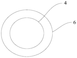
图7是本申请所述的采温采压线隔热结构的结构示意图一。
图8是本申请所述的采温采压线隔热结构的结构示意图二。
图标:1-电池模组,2-模组端板,3-电芯防爆阀,4-采温采压线,5-隔热引流板,51-基座,52-通孔,53-隔热片,54-导流口,6-隔热管,7-耐高温胶布。
下面结合附图,对本申请作详细的说明。
实施例1
如图3-6所示,一种储能电池模组隔热引流板5,包括基座51,基座51开设有若干个通孔52,通孔52的数量和外形适配于电芯防爆阀3(通孔52的数量、分布位置与电芯防爆阀3一致,且通孔52的形状与电芯防爆阀3基本一致,通孔52的大小与电芯防爆阀3基本一致,或通孔52的大小稍大于电芯防爆阀3),基座51的上表面覆盖有隔热片53,隔热片53能够耐受600℃以上的高温。隔热片53能够耐受600℃以上的高温,应理解为隔热片53在600℃的高温下至少能耐受30分钟不融化,满足储能电池过充测试的试验要求。
本申请的隔热引流板能够覆盖电池模组的模组端板,在储能电池过充测试过程中,若电芯热扩散电芯内部压力增大,顶开电芯防爆阀后,电芯热失控化学反应产生的高温高压混合可燃气液体破电芯防爆阀3后可以通过隔热引流板5的通孔52迅速排到模组外,防止高温高压混合可燃气液体在模组内部聚集;高温高压混合可燃气液体喷出后通过自身重力或者遇到电池箱内顶部后回落到具有耐高温的隔热片53,由于隔热片53的工作温度高于高温高压混合可燃气液体,所以能够起到将高温高压混合可燃气液体隔绝在模组外,防止高温高压混合可燃气液体掉落到电芯顶部,防止对电芯二次加热的作用。本申请的储能电池模组隔热引流板能够抑制过充测试过程中电池包起火。
优选的一种实施方式,隔热片53为白云母片、金云母片、热塑性聚酰亚胺片、氮化硼陶瓷板中的一种,或隔热片53为白云母片、金云母片、热塑性聚酰亚胺片、氮化硼陶瓷板中的若干种,不同种类的隔热片53上下叠放设置。保证隔热性能的基础上实现可制造性和经济性。
优选的一种实施方式,隔热片53的厚度大于或等于0.3mm。进一步优选的,隔热片53的厚度为0.4mm-0.6mm。保证足够的隔热性能。
优选的一种实施方式,隔热引流板5的上表面设有斜坡。进一步优选的,基座51的侧面开设有导流口54,导流口54与模组外部环境连通,导流口54位于斜坡最低处,导流口54可设置若干个。导流口54便于高温高压混合可燃气液体流到模组外部,防止高温高压混合可燃气液体在模组顶部聚集,避免高温高压混合可燃气液体在隔热片53的停留时间大于半小时后融化隔热片53、隔热引流板基座51后掉到电芯顶部。
优选的一种实施方式,基座51为PPS、GF组合注塑结构件,具体的,基座51由PPS+40%GF注塑而成。
实施例2
如图2、7所示,一种储能电池模组采温采压线隔热结构,包括采温采压线4,采温采压线4套设有隔热管6,隔热管6能够耐受600℃以上的高温。隔热管6能够耐受600℃以上的高温,应理解为隔热管6在600℃的高温下至少能耐受30分钟不融化,满足储能电池过充测试的试验要求。
本申请的储能电池模组采温采压线隔热结构,对采温采压线4进行了隔热加强处理,通过外包耐受600℃以上的高温的隔热管6,在储能电池过充测试过 程中,若锂电池过充热失控后,能够保证每一条导电线束相互分离,完全隔绝其相互搭接引起的内短路打火的情况。本申请的储能电池模组采温采压线隔热结构能够抑制过充测试过程中电池包起火,采温采压线4和隔热管6套设连接,便于对现有的采温采压线4进行改装。
优选的一种实施方式,隔热管6为硅树脂玻璃纤维管、高硅氧纤维管中的一种,或隔热管6为硅树脂玻璃纤维管、高硅氧纤维管中的若干种,不同种类的隔热管6依次套设。保证隔热性能的基础上实现可制造性和经济性。
优选的一种实施方式,隔热管6的长度短于采温采压线4,在端部预留一定长度用于焊接其他构件,例如铝排。
优选的一种实施方式,如图8所示,隔热管6包裹有耐高温胶布7,耐高温胶布7能够耐受200℃以上的高温,从而进一步对采温采压线进行隔热加强处理。耐高温胶布7能够耐受200℃以上的高温,应理解为耐高温胶布7在200℃的高温下至少能耐受30分钟不融化。
实施例3
如图1、2所示,一种储能电池,包括电池模组1,电池模组1的顶部设有模组端板2,模组端板2开设有电芯防爆阀3,还包括如实施例1的储能电池模组隔热引流板5,隔热引流板5覆盖在模组端板2上方。
实施例4
如图1、2所示,一种储能电池,包括电池模组1,还包括如实施例2的储能电池模组采温采压线隔热结构,采温采压线隔热结构位于电池模组1的内部。
实施例5
如图1、2所示,一种储能电池,包括电池模组1,电池模组1的顶部设有模组端板2,模组端板2开设有电芯防爆阀3,还包括如实施例1的储能电池模组隔热引流板5,隔热引流板5覆盖在模组端板2上方,还包括如实施例2的储能电池模组采温采压线隔热结构,采温采压线4位于电池模组1的内部。
本申请的储能电池,不仅设置了耐受600℃以上的隔热引流板5,能够将高温高压混合可燃气液体隔绝在模组外,防止高温高压混合可燃气液体掉落到电芯顶部,防止对电芯二次加热,而且设置了耐受600℃以上的高温的隔热管6,能够保证每一条导电线束相互分离,完全隔绝其相互搭接而内短路打火的情况。更进一步地,由于设置了隔热引流板5,还能够对模组内部的采温采压线4进行隔绝,防止喷出的高温高压混合可燃气液体落到采温采压线4表面,具有一定的协同作用,大大增大了整个电池模组的隔热功能,能够彻底抑制过充测试过程中电池包起火
优选的一种实施方式,基座51与模组端板2可拆卸式连接,具体的,可通过螺栓连接。便于对现有的储能电池进行微调,即可实现上述功能,可量产化。
以上所述仅为本申请的较佳实施例而已,并不用以限制本申请,凡在本申 请的精神和原则之内所作的任何修改、等同替换和改进等,均应包含在本申请的保护范围之内。
Claims (16)
- 一种储能电池模组隔热引流板,包括基座(51),所述基座(51)开设有若干个通孔(52),所述通孔(52)的数量和外形适配于电芯防爆阀(3),所述基座(51)的上表面覆盖有隔热片(53),所述隔热片(53)能够耐受600℃以上的高温。
- 根据权利要求1所述的储能电池模组隔热引流板,其中,所述隔热片(53)为白云母片、金云母片、热塑性聚酰亚胺片、氮化硼陶瓷板中的一种或若干种,不同种类的所述隔热片(53)上下叠放设置。
- 根据权利要求2所述的储能电池模组隔热引流板,其中,所述隔热片(53)的厚度大于或等于0.3mm。
- 根据权利要求3所述的储能电池模组隔热引流板,其中,所述隔热片(53)的厚度为0.4mm至0.6mm。
- 根据权利要求1所述的储能电池模组隔热引流板,其中,所述基座(51)的两端具有延伸出所述隔热片(53)的伸出部分,所述伸出部分用于固定所述基座(51)。
- 根据权利要求1所述的储能电池模组隔热引流板,其中,所述隔热引流板(5)的上表面设有斜坡。
- 根据权利要求6所述的储能电池模组隔热引流板,其中,所述基座(51)的侧面开设有导流口(54),所述导流口(54)位于斜坡最低处。
- 根据权利要求1-7任一所述的储能电池模组隔热引流板,其中,所述基座(51)为PPS、GF组合注塑结构件。
- 一种储能电池模组采温采压线隔热结构,包括采温采压线(4),所述采温采压线(4)外包有隔热管(6),所述隔热管(6)能够耐受600℃以上的高温。
- 根据权利要求9所述的储能电池模组采温采压线隔热结构,其中,所述隔热管(6)为硅树脂玻璃纤维管、高硅氧纤维管中的一种或若干种,不同种类的所述隔热管(6)依次套设。
- 根据权利要求10所述的储能电池模组采温采压线隔热结构,其中,所述隔热管(6)的长度小于所述采温采压线(4)。
- 根据权利要求9-11任一所述的储能电池模组采温采压线隔热结构,其中,所述隔热管(6)外包有耐高温胶布(7),所述耐高温胶布(7)能够耐受200℃以上的高温。
- 一种储能电池,包括电池模组(1),所述电池模组(1)的顶部设有模组端板(2),所述模组端板(2)开设有电芯防爆阀(3),还包括如权利要求1-8任一所述的储能电池模组隔热引流板(5),所述隔热引流板(5)覆盖在所述模组端板(2)上方。
- 一种储能电池,包括电池模组(1),,还包括如权利要求9-12任一所述的储能电池模组采温采压线隔热结构,所述采温采压线隔热结构位于所述电池模组(1)的内部。
- 一种储能电池,包括电池模组(1),所述电池模组(1)的顶部设有模组端板(2),所述模组端板(2)开设有电芯防爆阀(3),还包括如权利要求1-8任一所述的储能电池模组隔热引流板(5),所述隔热引流板(5)覆盖在所述模组端板(2)上方,还包括如权利要求9-12任一所述的储能电池模组采温采压线隔热结构,所述采温采压线隔热结构位于所述电池模组(1)的内部。
- 根据权利要求15所述的储能电池,其中,所述基座(51)与所述模组端板(2)可拆卸式连接。
Applications Claiming Priority (2)
| Application Number | Priority Date | Filing Date | Title |
|---|---|---|---|
| CN202222948913.9U CN219267784U (zh) | 2022-11-04 | 2022-11-04 | 储能电池及模组隔热引流板、采温采压线隔热结构 |
| CN202222948913.9 | 2022-11-04 |
Publications (1)
| Publication Number | Publication Date |
|---|---|
| WO2024093000A1 true WO2024093000A1 (zh) | 2024-05-10 |
Family
ID=86868759
Family Applications (1)
| Application Number | Title | Priority Date | Filing Date |
|---|---|---|---|
| PCT/CN2022/143164 Ceased WO2024093000A1 (zh) | 2022-11-04 | 2022-12-29 | 储能电池及模组隔热引流板、采温采压线隔热结构 |
Country Status (2)
| Country | Link |
|---|---|
| CN (1) | CN219267784U (zh) |
| WO (1) | WO2024093000A1 (zh) |
Families Citing this family (1)
| Publication number | Priority date | Publication date | Assignee | Title |
|---|---|---|---|---|
| CN115714222A (zh) * | 2022-11-04 | 2023-02-24 | 湖北亿纬动力有限公司 | 储能电池及模组隔热引流板、采温采压线隔热结构 |
Citations (9)
| Publication number | Priority date | Publication date | Assignee | Title |
|---|---|---|---|---|
| JP2010277975A (ja) * | 2009-06-01 | 2010-12-09 | Sumitomo Electric Ind Ltd | 超電導ケーブル線路 |
| CN203850018U (zh) * | 2014-05-07 | 2014-09-24 | 枞阳县越轩电气设备有限公司 | 一种耐高温线缆 |
| CN204668406U (zh) * | 2015-05-25 | 2015-09-23 | 宁德时代新能源科技有限公司 | 电池模组 |
| CN210325891U (zh) * | 2019-06-19 | 2020-04-14 | 安徽沃博源科技有限公司 | 一种电池模组 |
| CN211017155U (zh) * | 2019-10-29 | 2020-07-14 | 蜂巢能源科技有限公司 | 电芯模块、电池包及车辆 |
| CN111725455A (zh) * | 2020-06-12 | 2020-09-29 | 上汽通用汽车有限公司 | 电池模组及包括其的电池包 |
| CN216085488U (zh) * | 2021-11-09 | 2022-03-18 | 东莞市美森智造科技有限公司 | 用于新能源汽车电池包的温度采样线束 |
| CN216251036U (zh) * | 2021-09-03 | 2022-04-08 | 江苏正力新能电池技术有限公司 | 一种防热扩散的电池模组 |
| CN216529122U (zh) * | 2021-05-08 | 2022-05-13 | 江苏正力新能电池技术有限公司 | 一种用于电池模组的防火罩及其电池模组 |
-
2022
- 2022-11-04 CN CN202222948913.9U patent/CN219267784U/zh active Active
- 2022-12-29 WO PCT/CN2022/143164 patent/WO2024093000A1/zh not_active Ceased
Patent Citations (9)
| Publication number | Priority date | Publication date | Assignee | Title |
|---|---|---|---|---|
| JP2010277975A (ja) * | 2009-06-01 | 2010-12-09 | Sumitomo Electric Ind Ltd | 超電導ケーブル線路 |
| CN203850018U (zh) * | 2014-05-07 | 2014-09-24 | 枞阳县越轩电气设备有限公司 | 一种耐高温线缆 |
| CN204668406U (zh) * | 2015-05-25 | 2015-09-23 | 宁德时代新能源科技有限公司 | 电池模组 |
| CN210325891U (zh) * | 2019-06-19 | 2020-04-14 | 安徽沃博源科技有限公司 | 一种电池模组 |
| CN211017155U (zh) * | 2019-10-29 | 2020-07-14 | 蜂巢能源科技有限公司 | 电芯模块、电池包及车辆 |
| CN111725455A (zh) * | 2020-06-12 | 2020-09-29 | 上汽通用汽车有限公司 | 电池模组及包括其的电池包 |
| CN216529122U (zh) * | 2021-05-08 | 2022-05-13 | 江苏正力新能电池技术有限公司 | 一种用于电池模组的防火罩及其电池模组 |
| CN216251036U (zh) * | 2021-09-03 | 2022-04-08 | 江苏正力新能电池技术有限公司 | 一种防热扩散的电池模组 |
| CN216085488U (zh) * | 2021-11-09 | 2022-03-18 | 东莞市美森智造科技有限公司 | 用于新能源汽车电池包的温度采样线束 |
Also Published As
| Publication number | Publication date |
|---|---|
| CN219267784U (zh) | 2023-06-27 |
Similar Documents
| Publication | Publication Date | Title |
|---|---|---|
| Ouyang et al. | An experimental study on the thermal failure propagation in lithium-ion battery pack | |
| CN106646257B (zh) | 一种检测锂离子电池热失控扩散的测试平台和测试方法 | |
| Liu et al. | Self-heating ignition of open-circuit cylindrical Li-ion battery pile: Towards fire-safe storage and transport | |
| US20230170576A1 (en) | Battery Module | |
| CN206711984U (zh) | 一种高安全性的动力锂电池组 | |
| JP2018530875A (ja) | 携帯型電気エネルギー貯蔵セル用フレーム発明の背景 | |
| JPWO2010058587A1 (ja) | 電池パック | |
| CN210576161U (zh) | 一种具有高安全性能的锂离子电池及电池模组 | |
| US20220209339A1 (en) | Battery module, battery rack comprising same, and power storage device | |
| WO2018126511A1 (zh) | 一种防火电池组 | |
| CN219267784U (zh) | 储能电池及模组隔热引流板、采温采压线隔热结构 | |
| JP2023524001A (ja) | 熱拡散抑制構造を有する電池パック | |
| KR20220070834A (ko) | 열확산 억제 구조를 포함하는 전지팩 | |
| CN118073663A (zh) | 一种热失控触发电池及其测试方法 | |
| CN116565425A (zh) | 电池模组及电池包 | |
| CN111638302A (zh) | 一种锂离子电池火灾危险性等级分级试验检测方法 | |
| CN118073734A (zh) | 电池单体用壳体、电池及用电装置 | |
| Mao et al. | Effects and mechanisms of thickness-tunable aerogel thermal barriers on suppression of thermal runaway propagation in large-format prismatic lithium-ion batteries | |
| CN114865171A (zh) | 一种包裹内绝缘膜的电芯结构及其制备方法 | |
| CN115714222A (zh) | 储能电池及模组隔热引流板、采温采压线隔热结构 | |
| CN208862038U (zh) | 圆柱电池防爆不包边组合盖帽 | |
| CN205231129U (zh) | 一种高安全的锂离子电池组 | |
| CN204407434U (zh) | 一种安全的聚合物锂离子电池组结构 | |
| CN207021346U (zh) | 锂离子电池阻燃装置 | |
| CN112397829B (zh) | 一种具备高阻燃高阻热的模块及制备方法 |
Legal Events
| Date | Code | Title | Description |
|---|---|---|---|
| 121 | Ep: the epo has been informed by wipo that ep was designated in this application |
Ref document number: 22964294 Country of ref document: EP Kind code of ref document: A1 |
|
| NENP | Non-entry into the national phase |
Ref country code: DE |
|
| 122 | Ep: pct application non-entry in european phase |
Ref document number: 22964294 Country of ref document: EP Kind code of ref document: A1 |