WO2024090501A1 - 回転支持装置、及び軸支持装置の支持機構位置調整機構 - Google Patents
回転支持装置、及び軸支持装置の支持機構位置調整機構 Download PDFInfo
- Publication number
- WO2024090501A1 WO2024090501A1 PCT/JP2023/038614 JP2023038614W WO2024090501A1 WO 2024090501 A1 WO2024090501 A1 WO 2024090501A1 JP 2023038614 W JP2023038614 W JP 2023038614W WO 2024090501 A1 WO2024090501 A1 WO 2024090501A1
- Authority
- WO
- WIPO (PCT)
- Prior art keywords
- support
- shaft
- bearing housing
- axial
- side member
- Prior art date
- Legal status (The legal status is an assumption and is not a legal conclusion. Google has not performed a legal analysis and makes no representation as to the accuracy of the status listed.)
- Ceased
Links
Images










Classifications
-
- F—MECHANICAL ENGINEERING; LIGHTING; HEATING; WEAPONS; BLASTING
- F16—ENGINEERING ELEMENTS AND UNITS; GENERAL MEASURES FOR PRODUCING AND MAINTAINING EFFECTIVE FUNCTIONING OF MACHINES OR INSTALLATIONS; THERMAL INSULATION IN GENERAL
- F16C—SHAFTS; FLEXIBLE SHAFTS; ELEMENTS OR CRANKSHAFT MECHANISMS; ROTARY BODIES OTHER THAN GEARING ELEMENTS; BEARINGS
- F16C25/00—Bearings for exclusively rotary movement adjustable for wear or play
- F16C25/06—Ball or roller bearings
- F16C25/08—Ball or roller bearings self-adjusting
-
- F—MECHANICAL ENGINEERING; LIGHTING; HEATING; WEAPONS; BLASTING
- F16—ENGINEERING ELEMENTS AND UNITS; GENERAL MEASURES FOR PRODUCING AND MAINTAINING EFFECTIVE FUNCTIONING OF MACHINES OR INSTALLATIONS; THERMAL INSULATION IN GENERAL
- F16C—SHAFTS; FLEXIBLE SHAFTS; ELEMENTS OR CRANKSHAFT MECHANISMS; ROTARY BODIES OTHER THAN GEARING ELEMENTS; BEARINGS
- F16C19/00—Bearings with rolling contact, for exclusively rotary movement
- F16C19/54—Systems consisting of a plurality of bearings with rolling friction
-
- F—MECHANICAL ENGINEERING; LIGHTING; HEATING; WEAPONS; BLASTING
- F16—ENGINEERING ELEMENTS AND UNITS; GENERAL MEASURES FOR PRODUCING AND MAINTAINING EFFECTIVE FUNCTIONING OF MACHINES OR INSTALLATIONS; THERMAL INSULATION IN GENERAL
- F16C—SHAFTS; FLEXIBLE SHAFTS; ELEMENTS OR CRANKSHAFT MECHANISMS; ROTARY BODIES OTHER THAN GEARING ELEMENTS; BEARINGS
- F16C2322/00—Apparatus used in shaping articles
- F16C2322/39—General buildup of machine tools, e.g. spindles, slides, actuators
-
- F—MECHANICAL ENGINEERING; LIGHTING; HEATING; WEAPONS; BLASTING
- F16—ENGINEERING ELEMENTS AND UNITS; GENERAL MEASURES FOR PRODUCING AND MAINTAINING EFFECTIVE FUNCTIONING OF MACHINES OR INSTALLATIONS; THERMAL INSULATION IN GENERAL
- F16C—SHAFTS; FLEXIBLE SHAFTS; ELEMENTS OR CRANKSHAFT MECHANISMS; ROTARY BODIES OTHER THAN GEARING ELEMENTS; BEARINGS
- F16C2361/00—Apparatus or articles in engineering in general
- F16C2361/61—Toothed gear systems, e.g. support of pinion shafts
-
- F—MECHANICAL ENGINEERING; LIGHTING; HEATING; WEAPONS; BLASTING
- F16—ENGINEERING ELEMENTS AND UNITS; GENERAL MEASURES FOR PRODUCING AND MAINTAINING EFFECTIVE FUNCTIONING OF MACHINES OR INSTALLATIONS; THERMAL INSULATION IN GENERAL
- F16F—SPRINGS; SHOCK-ABSORBERS; MEANS FOR DAMPING VIBRATION
- F16F1/00—Springs
- F16F1/02—Springs made of steel or other material having low internal friction; Wound, torsion, leaf, cup, ring or the like springs, the material of the spring not being relevant
- F16F1/32—Belleville-type springs
-
- F—MECHANICAL ENGINEERING; LIGHTING; HEATING; WEAPONS; BLASTING
- F16—ENGINEERING ELEMENTS AND UNITS; GENERAL MEASURES FOR PRODUCING AND MAINTAINING EFFECTIVE FUNCTIONING OF MACHINES OR INSTALLATIONS; THERMAL INSULATION IN GENERAL
- F16F—SPRINGS; SHOCK-ABSORBERS; MEANS FOR DAMPING VIBRATION
- F16F15/00—Suppression of vibrations in systems; Means or arrangements for avoiding or reducing out-of-balance forces, e.g. due to motion
- F16F15/02—Suppression of vibrations of non-rotating, e.g. reciprocating systems; Suppression of vibrations of rotating systems by use of members not moving with the rotating systems
- F16F15/023—Suppression of vibrations of non-rotating, e.g. reciprocating systems; Suppression of vibrations of rotating systems by use of members not moving with the rotating systems using fluid means
-
- F—MECHANICAL ENGINEERING; LIGHTING; HEATING; WEAPONS; BLASTING
- F16—ENGINEERING ELEMENTS AND UNITS; GENERAL MEASURES FOR PRODUCING AND MAINTAINING EFFECTIVE FUNCTIONING OF MACHINES OR INSTALLATIONS; THERMAL INSULATION IN GENERAL
- F16F—SPRINGS; SHOCK-ABSORBERS; MEANS FOR DAMPING VIBRATION
- F16F2230/00—Purpose; Design features
- F16F2230/36—Holes, slots or the like
Definitions
- the present invention relates to a rotation support device that supports a rotating shaft such as a ball screw feed device or a spindle device, and a support mechanism position adjustment mechanism for a shaft support device that supports a shaft.
- a method of providing rigidity to the screw shaft of a ball screw device is to combine multiple angular bearings to apply preload and place them at one or both ends of the screw shaft.
- a common method is to support the screw shaft in a fixed position in the axial direction.
- a method is used in which tension is applied to the screw shaft in the axial direction in advance to elongate it by a predetermined amount.
- Patent Document 1 describes a method in which tension is applied to the feed screw (screw shaft) in advance by adjusting the axial dimension of the spacer, and when the feed screw elongates beyond the amount of pretension due to a temperature rise, It is described that the device is provided with a pretension mechanism that applies tension to the feed screw by moving a bearing in the axial direction using a disc spring or fluid pressure.
- a disc spring or an externally supplied fluid as seen in the pretension mechanism described in Patent Document 1, is usually arranged within a range where an excessive load is not applied to the bearing in the axial direction.
- the load weakens as the shaft elongates, so it can only handle an elongation of 3 to 4 degrees due to temperature rise. In machining centers, the temperature rise of the ball screw often exceeds 4 degrees, in which case the disc spring is not able to apply a sufficient load, resulting in a problem of reduced axial support rigidity.
- the present invention was made in consideration of the above-mentioned problems, and its purpose is to provide a rotation support device and a support mechanism position adjustment mechanism for the shaft support device that can continuously and stably maintain axial support rigidity even if the axial length of the rotating shaft changes due to the effects of heat.
- a rotary support device including a rotary shaft and a pair of support mechanisms that rotatably support both axial ends of the rotary shaft,
- One of the pair of support mechanisms is a bearing unit including a bearing housing and a bearing that rotatably supports the rotating shaft relative to the bearing housing and is capable of supporting an axial load;
- a support base through which the rotation shaft passes or which is arranged around the rotation shaft;
- a housing position adjustment mechanism disposed between the bearing unit and the support base; Equipped with
- the housing position adjustment mechanism includes: A support base side member provided on the support base side and through which the rotation shaft passes or around the rotation shaft; a bearing housing side member provided on the bearing housing side, the rotation shaft passing through the bearing housing side member or disposed around the rotation shaft, the bearing housing side member being movable in the axial direction relative to the support base side member; a pressure chamber formed between the support base side member and the bearing housing side member, a storage chamber formed in the support base side member or the bearing housing side member
- the rotary support device of the present invention can continuously and stably maintain axial support rigidity even if the axial length of the rotating shaft changes due to the effects of heat, and can damp vibrations in the axial and radial directions.
- the support mechanism position adjustment mechanism of the shaft support device of the present invention can continuously and stably maintain axial support rigidity even if the axial length of the shaft changes due to the effects of heat, and can damp vibrations in the axial and radial directions.
- FIG. 1 is a cross-sectional view of a table feed system of a machine tool to which a ball screw feed device according to a first embodiment of the present invention is applied; 2 is an enlarged cross-sectional view of a support mechanism including a housing position adjustment mechanism shown in FIG. 1 .
- FIG. 3 is a view taken along the arrow A in FIG. 2 .
- FIG. 11 is a cross-sectional view showing a modified example of the disc spring.
- 11A to 11C are cross-sectional views showing first to third modified examples of a hollow member disposed in a pressure chamber.
- 13A and 13B are cross-sectional views showing fourth and fifth modified examples of a hollow member.
- FIG. 13 is a cross-sectional view showing a sixth modified example of a hollow member.
- FIG. 4 is a view corresponding to FIG. 2 of a ball screw feed device according to a second embodiment of the present invention.
- FIG. 13 is an enlarged view of a portion XIII in FIG. 12 .
- FIG. 13A to 13C are enlarged cross-sectional views of a main portion showing an example in which a wear-resistant member is applied to a seal groove of a ball screw feed device according to a modified example of the second embodiment.
- FIG. 10 is a view corresponding to FIG. 2 of a ball screw feed device according to a third embodiment of the present invention.
- FIG. 10 is a view corresponding to FIG. 2 of a ball screw feed device according to a fourth embodiment of the present invention.
- FIG. 3 is a view corresponding to FIG. 2 , showing a pair of angular ball bearings of a bearing unit according to a second modified example of the present invention, arranged back-to-back.
- FIG. 1A is a schematic side view showing a first example in which a housing position adjustment mechanism is composed of multiple pressure chambers
- FIG. 1B is a schematic side view showing a second example in which a housing position adjustment mechanism is composed of multiple pressure chambers
- 1A is a schematic side view showing a third example in which the housing position adjustment mechanism is composed of multiple pressure chambers
- FIG. 1B is a schematic side view showing a fourth example in which the housing position adjustment mechanism is composed of multiple pressure chambers
- 13 is a schematic side view showing a fifth example in which the housing position adjustment mechanism is constituted by a plurality of pressure chambers.
- FIG. 10 is a view corresponding to FIG. 2 of a ball screw feed device according to a fifth embodiment of the present invention.
- FIG. 13 is a view corresponding to FIG. 2 of a ball screw feed device according to a first modified example of the fifth embodiment of the present invention.
- FIG. 13 is a view corresponding to FIG. 2 of a ball screw feed device according to a second modified example of the fifth embodiment.
- FIG. 26 is an enlarged view of part XXVI in FIG. 25 .
- FIG. 2 is a view of a ball screw feed device according to a third modified example of the fifth embodiment.
- FIG. 2 is a view of a ball screw feed device according to a fourth modified example of the fifth embodiment, the view corresponding to FIG. 2 .
- 3A is an enlarged cross-sectional view corresponding to FIG. 2 in a phase in which an oil supply passage is formed in a bearing housing side member in order to fill a pressure chamber with working fluid
- FIG. 3B is a cross-sectional view showing a modified example of the lock plug bolt of FIG. 29(a) is a cross-sectional view of a stopper plug used in place of the stopper bolt of FIG.
- FIG. 29(a), (b) is a cross-sectional view showing an example in which the stopper plug of (a) is combined with a disk-shaped member
- (c) is a cross-sectional view showing a modified example of the disk-shaped member of (b)
- (d) is a cross-sectional view showing another modified example of the disk-shaped member of (b).
- 13 is a cross-sectional view of a table feed system of a machine tool to which a ball screw feed device according to a modified example of the present invention is applied.
- 11 is a cross-sectional view showing a first example of a housing position adjustment mechanism in which a support base is disposed on an axial end side with respect to a bearing unit.
- FIG. 13 is a cross-sectional view showing a second example of a housing position adjustment mechanism in which a support base is disposed on an axial end side with respect to a bearing unit.
- FIG. 13 is a cross-sectional view showing a third example of a housing position adjustment mechanism in which a support base is disposed on the axial end side of a bearing unit.
- FIG. 13 is a cross-sectional view showing a fourth example of a housing position adjustment mechanism in which a support base is disposed on the axial end side of a bearing unit.
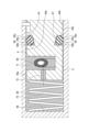
- FIG. 1 is a cross-sectional view showing a rotation support device according to the present invention.
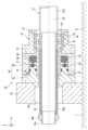
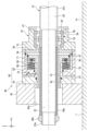
- FIG. 4 is a cross-sectional view showing another rotary support device according to the present invention.
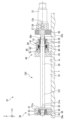
- 1 is a cross-sectional view showing a shaft support device to which a support mechanism position adjustment mechanism according to the present invention is applied;
- FIG. 39 is an enlarged view of portion XXXIX of FIG. 38.
- FIG. 1 shows a table feed system of a machine tool to which the ball screw feed device of the first embodiment is applied.
- the axial direction of a screw shaft 21 of a ball screw feed device 20 (left-right direction in Fig. 1) is defined as the X direction
- the direction parallel to the mounting surface 1a of the base 1 and perpendicular to the axial direction of the screw shaft 21 (perpendicular to the paper surface of Fig. 1) is defined as the Y direction
- the direction perpendicular to the mounting surface 1a of the base 1 (up-down direction in Fig. 1) is defined as the Z direction.
- dotted lines indicate bolt fastening points.
- the table feed system 10 includes a moving table 11 fixed to a nut 23 of a ball screw feed device 20, and is configured so that the moving table 11 can move freely in the X direction by driving the screw shaft 21 of the ball screw feed device 20 with a drive motor 12.
- the moving table 11 is provided with a pair of linear guides 13 (only one is shown in FIG. 1) on both sides of the ball screw feed device 20 in the Y direction.
- Each linear guide 13 includes a guide rail 15 arranged parallel to the screw shaft 21 via a rail mounting base 14 on the base 1, and two sliders 16 fixed to the underside of the moving table 11 and straddling the guide rails 15. Then, by rotating the screw shaft 21 with the drive motor 12, the moving table 11 is guided by the pair of linear guides 13 and moves back and forth linearly together with the nut 23.
- the ball screw feed device 20 comprises a screw shaft 21 having a helical screw groove 21b formed on its outer circumferential surface, a nut 23 arranged around the screw shaft 21 and having a helical screw groove (not shown) formed on its inner circumferential surface, which fits into a nut housing 22 fixed to the underside of the moving table 11, and a number of balls (not shown) arranged to roll freely between the screw groove of the nut 23 and the screw groove 21b of the screw shaft 21.
- the screw shaft 21 has a large diameter section 24 formed in the axial center and with a screw groove 21b, and small diameter sections 25 formed on both axial ends of the large diameter section 24.
- a male thread 25a is formed on the outer peripheral surface at the tip end of the small diameter section 25, and a small diameter shaft section 27 is provided at the tip of one side of the screw shaft 21 (the right side in the figure).
- the small diameter shaft section 27 is connected to the rotating shaft 12a of the drive motor 12 via a coupling 28.
- one side of the screw shaft 21, to which the drive motor 12 is connected is rotatably supported by a first support mechanism 30, and the other side of the screw shaft 21 (the left side in the figure) is rotatably supported by a second support mechanism 40.
- the first support mechanism 30 comprises a fixed-side bearing housing 31 fixed to the base 1, and a pair of angular ball bearings 33, 33 arranged in a face-to-face combination that rotatably supports the screw shaft 21 relative to the fixed-side bearing housing 31.
- Each of the pair of angular ball bearings 33, 33 comprises an outer ring 34 fitted inside the fixed-side bearing housing 31, an inner ring 35 fitted outside the small diameter portion 25 of the screw shaft 21, and a number of balls 36 arranged to roll freely with a contact angle between the outer ring 34 and the inner ring 35.
- the pair of angular ball bearings 33, 33 has an outer ring 34 of the axially inner angular ball bearing 33 abutted against the inward flange 31a of the fixed bearing housing 31, and an outer ring 34 of the axially outer angular ball bearing 33 fixed by an outer ring holder 37 fastened to the fixed bearing housing 31. Also, an inner ring 35 of the axially inner angular ball bearing 33 abuts against a step 21a between the large diameter portion 24 and the small diameter portion 25 of the screw shaft 21, and the inner ring 35 of the axially outer angular ball bearing 33 is fastened by a fastening nut 38a that screws onto the male thread 25a. Therefore, the first support mechanism 30 supports the screw shaft 21 with the axial position of the screw shaft 21 fixed.
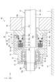
- the second support mechanism 40 includes a bearing unit 41 disposed at the other end of the screw shaft 21, a support base 43 fixed to the base 1 on the axial center side of the bearing unit 41, and a housing position adjustment mechanism 60 disposed between the bearing unit 41 and the support base 43.
- the support base 43 is provided with a through hole 43a through which the screw shaft 21 passes.
- the bearing unit 41 includes a movable-side bearing housing 51 and a pair of angular ball bearings 53 , 53 that rotatably support the screw shaft 21 relative to the movable-side bearing housing 51 .
- a pair of angular ball bearings 53, 53 comprise an outer ring 54 fitted inside the moving side bearing housing 51, an inner ring 55 fitted outside the small diameter portion 25 of the screw shaft 21, and a plurality of balls 56 arranged freely rotatably between the outer ring 54 and the inner ring 55 with a contact angle.
- the outer ring 54 of the angular ball bearing 53 on the axially inner side is brought into contact with the inward flange 51a of the moving-side bearing housing 51, and the outer ring 54 of the angular ball bearing 53 on the axially outer side is fastened by an outer ring holder 47 fastened and fixed to the moving-side bearing housing 51, so that each outer ring 54, 54 is positioned in the axial direction with respect to the moving-side bearing housing 51.
- the inner ring 55 of the angular ball bearing 53 arranged on the axially outer side is fastened via a spacer 48 by a fastening nut 38b that screws onto the male thread 25a.
- the pair of angular ball bearings 53, 53, the moving-side bearing housing 51, and the outer ring holder 47 can be unitized as the bearing unit 41 with a predetermined preload applied to the pair of angular ball bearings 53, 53 arranged in face-to-face combination, and this bearing unit 41 can be easily attached to the screw shaft 21 and the housing position adjustment mechanism 60.
- the moving-side bearing housing 51 can also be integrated with the bearing housing side member 62 if necessary.
- the housing position adjustment mechanism 60 is provided on the support base 43 side and includes a support base side member 61 through which the screw shaft 21 passes, and a bearing housing side member 62 provided on the movable bearing housing 51 side and movable in the axial direction relative to the support base side member 61.
- the support base side member 61 and the bearing housing side member 62 face each other in the axial direction.
- the support base side member 61 is fixed to the support base 43 with a plurality of bolts (not shown) by fitting the annular portion 61a protruding toward the support base 43 into the through hole 43a of the support base 43.
- the bearing housing side member 62 is fixed to the moving side bearing housing 51 with a plurality of bolts 63 (see Figure 3) by fitting the annular portion 62a protruding toward the moving side bearing housing 51 into the inward flange 51a.
- a bottomed annular recess 64 that opens toward the support base side member 61 is provided on the side surface of the bearing housing side member 62 facing the support base side member 61.
- a ring-shaped protrusion 65 that protrudes into the ring-shaped recess 64 toward the bearing housing side member 62 (the other axial side) is provided on the side surface of the support base side member 61 facing the bearing housing side member 62.
- the ring-shaped recess 64 and the ring-shaped protrusion 65 fit together slidably in the axial direction, and a ring-shaped pressure chamber 66 is formed between the bottom surface, inward surface 64a, and outward surface 64b of the ring-shaped recess 64 and the tip surface of the ring-shaped protrusion 65.
- annular storage chamber 71 is formed within the annular protrusion 65, and an orifice 72 is formed along the axial direction at least at one location in the circumferential direction (two locations in FIG. 2) to connect the storage chamber 71 to the pressure chamber 66.
- the storage chamber 71 is formed in a disk groove shape, opening onto the outward surface 65a of the annular protrusion 65, closer to the tip surface of the annular protrusion 65 than the groove in which the O-ring 67, described below, is disposed.
- the pressure chamber 66, the storage chamber 71, and the orifice 72 contain a working fluid, for example, hydraulic oil 70, in a compressed state, and the hydraulic oil 70 flows through the pressure chamber 66, the storage chamber 71, and the orifice 72, including the gap g between the outward surface 65a of the annular convex portion 65 and the inward surface 64a of the annular concave portion 64.
- a working fluid for example, hydraulic oil 70
- a plurality of disc springs 80 which are elastic members, are arranged in a compressed state between the opposing axial end faces of the support base side member 61 and the bearing housing side member 62, i.e., between the bottom surface of the annular recess 64 and the tip surface of the annular protrusion 65. Therefore, the space in the pressure chamber 66 other than the plurality of disc springs 80 is filled with the hydraulic oil 70. Furthermore, a hollow member 90 configured to have a sealed structure is disposed in the storage chamber 71, In the storage chamber 71 , the space other than the hollow member 90 is filled with the hydraulic oil 70 .
- the hydraulic oil 70 is a hydraulic fluid that has an elastic effect when an external force is applied, and its rigidity has been industrially confirmed, and it is given rigidity when compressed.
- the bulk modulus of hydraulic oil is affected by the inclusion of gas (see non-patent literature (Deshimaru Junichi and Tanaka Hirohisa, "Measurement of the bulk modulus of hydraulic oil", Hydraulics and Pneumatics, 1988, Vol. 19, No. 7, pp. 580-583)).
- the type of hydraulic oil and gas is appropriately selected so that when the pressure chamber 66 expands in the axial direction in response to the axial elongation of the screw shaft 21, the pressure acting on the bearing housing side member 62 gives the screw shaft the desired axial stiffness, even if there is a temperature rise of more than 4 degrees.
- the working fluid is not limited to oil, but may be any liquid such as water or a gas, as long as it has an elastic effect and exhibits rigidity when compressed.
- the magnitude of the axial load applied to the screw shaft 21 by the working fluid may be set by considering the tightening amount of the fastening nut 38b, as well as by considering the volume expansion due to a temperature rise of the working fluid caused by a temperature rise of the angular ball bearings 53, 53 and the screw shaft 21 during operation of the ball screw feed device 20.
- the magnitude of the axial load applied to the screw shaft 21 by the working fluid may be set by considering the volume expansion due to a temperature rise of the working fluid caused by an environmental change around the ball screw feed device 20 during operation of the ball screw feed device 20.
- the multiple disc springs 80 function as series springs, they are stacked in the axial direction so that the convex sides of adjacent disc springs 80 face each other and the concave sides face each other, as shown in Figure 2.
- the multiple disc springs 80 function as parallel springs, they are stacked in the axial direction so that the convex sides of adjacent disc springs 80 face each other and the concave sides face each other, as shown in Figure 2.
- the multiple disc springs 80 function as parallel springs, they are stacked in the axial direction so that the convex sides of adjacent disc springs 80 face each other and are aligned in the same direction, as not shown.
- the hollow member 90 is a life-ring-like structure formed in an annular shape with an elliptical cross section having an inner diameter larger than the outward surface 64b of the annular recess 64 and an outer diameter smaller than the inward surface 64a of the annular recess 64, and is made of elastically deformable rubber, resin, metal, etc., or a combination of these.
- the hollow member 90 contains any liquid or gas that has an elastic effect when an external force is applied and has industrially confirmed rigidity. However, from the viewpoint of ease of assembly, it is preferable that the hollow member 90 be structured so as to be divided into a plurality of parts in the circumferential direction.
- an O-ring 67 is attached between the outward surface 65a of the annular convex portion 65 and the inward surface 64a of the annular recess 64, and between the inward surface 65b of the annular convex portion 65 and the outward surface 64b of the annular recess 64.
- the O-ring 67 is disposed in an annular seal groove 68 formed on the outward surface 65a and the inward surface 65b of the annular convex portion 65, and is in sliding contact with the inward surface 64a and the outward surface 64b of the opposing annular recess 64 to seal the radial gap between the outward surface 65a of the annular convex portion 65 and the inward surface 64a of the annular recess 64, and the radial gap between the inward surface 65b of the annular convex portion 65 and the outward surface 64b of the annular recess 64.
- the seal groove 68 may be formed on the inward surface 64a and the outward surface 64b of the annular recess 64.
- O-ring 67 and one seal groove 68 are disposed between each opposing surface, a plurality of them may be disposed. In this way, the O-ring 67 prevents leakage of the hydraulic oil 70 filled in the pressure chamber 66 and the storage chamber 71.
- the O-ring 67 may be subjected to a surface treatment that provides abrasion resistance, etc., in order to prevent wear.
- a rotation prevention mechanism 75 is provided between the support base side member 61 and the bearing housing side member 62 to prevent relative rotation between them.
- the bearing housing side member 62 has a through hole 77 formed in at least one location in the circumferential direction, which penetrates radially so that the tip of the positioning pin 76 protrudes from the inward surface 64a of the annular recess 64.
- the tip of the positioning pin 76 is inserted into a long hole 78 formed along the axial direction on the outward surface 65a of the annular protrusion 65 of the support base side member 61 so that the bearing housing side member 62 can move in the axial direction.
- the positioning pin 76 may be replaced by a rotational positioning key (not shown) having a similar rotation prevention function, which is inserted into the long hole 78 so that the bearing housing side member 62 can move in the axial direction.
- the hydraulic oil 70 and the multiple disc springs 80 are accommodated in the pressure chamber 66, and the hydraulic oil 70 and the hollow member 90 are accommodated in the storage chamber 71, and then the fastening nut 38b is tightened to press the bearing housing side member 62 into the support base side member 61 via the pair of angular ball bearings 53, 53 and the movable side bearing housing 51.
- the hydraulic oil 70 is compressed, and pressure in the screw axis direction is applied to the hydraulic oil 70, while the multiple disc springs 80 are compressed, and pressure in the screw axis direction is applied to the multiple disc springs 80, and further, the hollow member 90 is compressed, and pressure in the screw axis direction is also applied to the hollow member 90.
- the pressure of the hydraulic oil 70 and the multiple disc springs 80 contained in the pressure chamber 66, and the pressure of the hydraulic oil 70 and the hollow member 90 contained in the storage chamber 71 can each be controlled to any desired magnitude by the amount of tightening of the fastening nut 38b.
- the magnitude of the axial load applied to the screw shaft 21 can be set to any desired magnitude by the fastening nut 38b.
- the magnitude of the axial load applied to the screw shaft 21 by the hydraulic oil 70 can be set by the amount of tightening of the fastening nut 38b, as described above, and can also be set by taking into consideration the volume expansion of the hydraulic oil 70 due to a rise in temperature when the ball screw feed device 20 is in operation.
- the operation of the ball screw feed device 20 of this embodiment will be described.
- the screw shaft 21 is rotated by the drive motor 12, and the moving table 11 fixed to the nut 23 is caused to move in a reciprocating linear motion.
- the drive motor 12, the angular ball bearings 33, 53, the nut 23, etc. generate heat, the temperature of the ball screw feed device 20 gradually increases, and the screw shaft 21 extends in the axial direction due to thermal expansion.
- the hydraulic oil 70, the multiple disc springs 80, and the hollow member 90 are designed to continue to press the bearing unit 41 and the bearing housing side member 62 to the left even when the screw shaft 21 expands in the axial direction.
- the hydraulic oil 70, the pressure chamber 66, and the reservoir chamber 71 have a large degree of design freedom, and by appropriately selecting the physical properties of the hydraulic oil 70 filled in the pressure chamber and the size and shape of the pressure chamber and the reservoir chamber, the pressure of the hydraulic oil 70 can be exerted in addition to the pressure of the multiple disc springs 80 and the hollow member 90, thereby providing a sufficient and appropriate load in response to greater axial expansion.
- the pair of angular ball bearings 53, 53 can be moved axially to maintain the axial support rigidity, and the axial rigidity of the ball screw feed device 20 is stabilized.
- the hydraulic oil 70 can flow through the pressure chamber 66 and the reservoir chamber 71 via an orifice, so that the load pressing the bearing unit 41 and the bearing housing side member 62 can be shared among the multiple disc springs 80, hollow member 90, and hydraulic oil 70, and the design can be made such that the load changes in response to the axial elongation of the screw shaft 21 even if the temperature rises by more than 4 degrees.
- the pair of angular ball bearings 33, 33 are maintained as fixed supports, and the axial rigidity of the ball screw feed device 20 is stabilized.
- the ball screw feed device 20 of this embodiment it is not necessary to install external devices such as an accumulator or pump for supplying hydraulic oil 70 to the pressure chamber 66 and the storage chamber 71, and the housing position adjustment mechanism 60 can be simplified. As a result, the pressure in the pressure chamber 66 and the storage chamber 71 can be maintained with as little change as possible without consuming energy supplied from the outside.
- external devices such as an accumulator or pump for supplying hydraulic oil 70 to the pressure chamber 66 and the storage chamber 71
- the housing position adjustment mechanism 60 can be simplified.
- the pressure in the pressure chamber 66 and the storage chamber 71 can be maintained with as little change as possible without consuming energy supplied from the outside.
- the O-ring 67 in this embodiment also functions as a damping mechanism. That is, when a workpiece placed on the movable table 11 is machined, the vibration generated in the movable table 11 also causes the screw shaft 21, which has a relatively low rigidity, to vibrate. The vibration of the screw shaft 21 is also transmitted to the bearing housing side member 62 via the pair of angular ball bearings 33, 33 and the movable side bearing housing 51, but the vibration of the bearing housing side member 62 is damped by the O-ring 67 between the bearing housing side member 62 and the support base side member 61. Therefore, the vibration of the screw shaft 21 can also be damped, and disturbance of the machining surface quality of the workpiece placed on the movable table 11 can be suppressed. In this case, the O-ring 67 arranged between the bearing housing side member 62 and the support base side member 61 can not only dampen vibrations in the axial direction of the screw shaft 21, but also dampen vibrations in the radial direction of the screw shaft 21.
- the hydraulic oil 70 of the housing position adjustment mechanism 60 is stored not only in the pressure chamber 66, the storage chamber 71, and the orifice 72, but also in the gaps between the outward surface 65a of the annular convex portion 65 and the inward surface 64a of the annular concave portion 64, and between the inward surface 65b of the annular convex portion 65 and the outward surface 64b of the annular concave portion 64, and on the pressure chamber 66 side of the O-ring 67. Therefore, when the hydraulic oil 70 is compressed, pressure acts on the hydraulic oil 70 not only in the axial direction but also in the radial direction. As a result, the bearing housing side member 62 is supported by the support base side member 61 with a sufficient and appropriate radial load. As a result, the housing position adjustment mechanism 60 can provide radial support rigidity to the screw shaft 21 via the pair of angular ball bearings 53, 53 and the bearing housing 51, and can also have an aligning function for the screw shaft 21.
- the O-ring 67 can dampen this vibration.
- the hydraulic oil 70 passes through the orifice 72 and the gap g between the outward surface 65a of the annular convex portion 65 and the inward surface 64a of the annular concave portion 64, thereby damping the vibration. Therefore, similar to the O-ring 67 described above, when machining a workpiece placed on the moving table 11, the vibration transmitted to the screw shaft 21 can be damped, further improving the quality of the machined surface of the workpiece.
- the hydraulic oil 70 in the pressure chamber 66 exerts an orifice effect by passing through the minute gaps that arise at the contact points between the disc springs 80 or between the disc springs 80 and the inner surface of the pressure chamber 66, thereby damping the vibrations of the screw shaft 21 and the vibrations of the multiple disc springs 80 described above.
- hydraulic oil 70 and multiple disc springs 80 are contained in the pressure chamber 66, hydraulic oil 70 and hollow member 90 are contained in the storage chamber 71, and the pressure chamber 66 and storage chamber 71 are connected through an orifice 72.
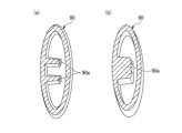
- the disk-shaped disc spring 80 may have multiple through holes 80a that penetrate the conical plate portion in the axial direction, and may also have multiple slits (not shown). This allows the disc spring 80 to function as an orifice, and the hydraulic oil 70 to flow through the multiple through holes 80a and slits, thereby providing an even greater damping effect.
- the hollow member 90 has an elliptical cross section, but this is not limited thereto, and it may have a rectangular cross section as shown in FIG. 5(a), or a triangular cross section as shown in FIG. 5(b).
- the hollow member 90 is formed in a ring shape, but this is not limited thereto, and it may have one or more spherical shapes, semicircular arc shapes (not shown), etc. as shown in FIG. 5(c).
- FIGS. 6(a) and 6(b) are cross-sectional views of hollow member 90 formed in an annular shape according to modified examples of this embodiment.
- hollow member 90 may be configured to have at least one rib 90a protruding from its inner peripheral surface.
- the shape of rib 90a may be formed in an annular shape around the entire circumference of hollow member 90, or may be formed partially in the circumferential direction of hollow member 90.
- rib 90a may be formed in a portion of the circumferential direction of the ring-shaped cross section.
- the hollow member 90 By providing the hollow member 90 with such ribs 90a, when the hollow member 90 is compressed and deformed due to the pressure generated in the storage chamber 71, the ribs 90a come into contact with the inner peripheral surface facing the ribs 90a, thereby preventing the hollow member 90 from being excessively deformed, such as by plastic deformation. This also makes it possible to prevent the liquid or gas contained in the hollow member 90 from leaking out into the storage chamber 71.
- the rib 90a can also be applied to hollow members having shapes other than annular shapes, and may be formed inside the above-mentioned spherical or semicircular hollow members, for example.
- the hollow member 90 may be provided with at least one outer layer 100 that covers (molds) the entire surface. This makes it possible to change the rigidity of the hollow member 90 and to protect the surface of the hollow member 90 from the working fluid such as the working oil 70.
- the outer layer 100 may be made of the same material as the hollow member, but may also be made of a different material.
- the hollow member 90 is molded as a single piece without any seams, which makes it difficult for localized stress concentration to occur and allows for easy manufacture.
- the hollow member 90 is not limited to being molded as a single piece, and may be, for example, a combined body with a hollow cross section formed by integrating two or more members via the edges of these two or more members.
- the hollow member 90 may be formed to have a hollow cross section by bending the members and joining the edges of the members.
- the hollow member 90 is a combined body with a hollow cross section, which is formed by combining and integrating two or more ring-shaped members 101, 102 via ribs 101a, 102a formed on both peripheries of these members.
- the ring-shaped members 101, 102 can be combined by any appropriate method selected from among adhesion, fusion bonding, connection by a mechanical locking mechanism, etc.
- the hollow member 90 is composed of an outer diameter side ring-shaped member 101 and an inner diameter side ring-shaped member 102, which are divided into two in the radial direction, and the circular arc-shaped portions 101b and 102b of the ring-shaped members 101 and 102 form a hollow cross section.
- the ribs 101a and 102a are joined to each other by gluing or melt-jointing, with one of them being longer than the other.
- the tip of the long rib 102a may be bent so that the rib 102a covers the side of the short rib 101a.
- the ribs may be joined to seal the inside with a continuous or discontinuous U-shaped fastening structure, with the tip of the long rib 102a covering the tip of the short rib 101a.
- the hollow member 90 is composed of a left ring-shaped member 101 and a right ring-shaped member 102 that are divided in two in the axial direction, and the circular arc-shaped portions 101b and 102b of the ring-shaped members 101 and 102 form a hollow cross section.
- the ribs 101a and 102a are joined to each other by gluing or melt-jointing, with one of them being longer than the other.
- the tip of the long rib 102a may be bent so that the rib 102a covers the side of the short rib 101a.
- the ribs may be joined to seal the inside with a continuous or discontinuous U-shaped fastening structure, with the tip of the long rib 102a covering the tip of the short rib 101a.
- the hollow member 90 may have seal grooves 101a1, 102a1 formed near the edges of at least one of the opposing surfaces of the ribs 101a, 102a of the two divided ring-shaped members 101, 102 (rib 101a in Figure 10(a) and ribs 101a, 102a in Figure 10(b)), and a seal member such as an O-ring 103 may be placed therein to improve the internal sealing performance.
- a hollow member 90 is formed by bending a ring-shaped member 104 having a band-like cross section so as to have a hollow cross section all around, and joining ribs 104a, 104b formed on the periphery of the ring-shaped member 104.
- the ring-shaped member 104 can be joined by adhesion, fusion bonding, An appropriate method may be selected from among connection using a mechanical locking mechanism.
- one of the ribs 104a, 104b is longer than the other and is joined to each other by adhesion or melt bonding.
- the tip of the long rib 104b may be bent so that the rib 104b covers the side of the short rib 104a.
- the tip of the long rib 104b may be joined to cover the tip of the short rib 104a with a continuous or discontinuous U-shaped fastening structure to seal the inside.
- the deformable hollow member 90 can be easily manufactured by a method other than the integral molding.
- the peripheral portions of the ring-shaped members 101, 102, and 104 are as shown in FIGS.
- the ribs 101a, 102a, 104a, and 104b may not be included. That is, the hollow member 90 may be formed by joining the peripheral portions of the arc-shaped portions 101b and 102b of the ring-shaped members 101 and 102 by an appropriate joining method, or the hollow member 90 may be formed by joining the peripheral portion of the curved portion of the ring-shaped member 104 by an appropriate joining method.
- the configurations shown in Figures 8 to 11 are not limited to those that assume ring-shaped members, but can also be applied to planar or curved members for constructing spherical or semicircular arc shapes, as shown in Figure 4 (c).
- the storage chamber 71 is formed on the outer diameter side so as to open to the outward surface 65a of the annular convex portion 65, but it may also be formed on the inner diameter side so as to open to the inward surface 65b of the annular convex portion 65.
- the cross-sectional shape and length of the orifice 72 may be arbitrarily formed as long as they provide a damping function.
- the support base side member 61 may be configured integrally with the support base 43, and the bearing housing side member 62 may also be configured integrally with the movable side bearing housing 51.
- a ball screw feed device according to a second embodiment of the present invention will be described with reference to Fig. 12 and Fig. 13. Note that in this embodiment, the configuration of the housing position adjustment mechanism 60 of the second support mechanism 40 is different from that of the first embodiment.
- the seal groove 68 formed on the outward surface 65a and the inward surface 65b of the annular protrusion 65 is composed of a tapered surface 69a whose depth becomes shallower as it moves away from the pressure chamber 66 side, and both axial side surfaces 69b, 69c that are circular and extend radially from both axial end edges of the tapered surface 69a.
- the axial distance between the axial side surfaces 69b, 69c is wider than the axial width of the O-ring 67 when it is elastically deformed and fitted into the seal groove 68. This allows the hydraulic oil 70 that passes through the gap g from the pressure chamber 66 to flow around the boundary between the axial side surface 69b, which has a deeper groove, and the tapered surface 69a.
- the O-ring 67 further improves the sealing performance due to the wedge structure between the tapered surface 69a of the seal groove 68 and the inward surface 64a and outward surface 64b of the opposing annular recess 64.
- a wear-resistant member 59 may be interposed between the O-ring 67 and at least one of the inward surface 64a of the annular recess 64 and the outward surface 65a of the annular protrusion 65 (in this embodiment, the tapered surface 69a of the seal groove 68 formed on the outward surface 65a).
- the wear-resistant member 59 may be formed as an annular member with a U-shaped cross section so as to be positioned between the outer peripheral surface of the O-ring 67 and the inward surface 64a of the annular recess 64, and between the inner peripheral surface of the O-ring 67 and the tapered surface 69a of the seal groove 68 formed on the outward surface 65a of the annular protrusion 65.
- the wear-resistant member 59 may be formed as an annular member with a straight cross section so as to be positioned between the inner peripheral surface of the O-ring 67 and the tapered surface 69a of the seal groove 68 formed in the outward surface 65a of the annular convex portion 65. Furthermore, as shown in FIG. 14(c), the wear-resistant member 59 may be formed as an annular member with a straight cross section so as to be positioned between the outer peripheral surface of the O-ring 67 and the inward surface 64a of the annular recess 64.
- the wear-resistant member 59 may be made of, for example, a resin material such as a fluororesin or a metal material that has been subjected to an appropriate surface treatment.
- wear-resistant member 59 can disperse the stress concentration on O-ring 67, thereby suppressing damage such as wear to O-ring 67 and the contact surface with O-ring 67.
- the wear-resistant member 59 may also be interposed between the O-ring 67 and at least one of the outward surface 64b of the annular recess 64 and the inward surface 65b of the annular protrusion 65 (the tapered surface 69a of the seal groove 68 formed on the inward surface 65b in FIG. 13), as shown in FIG. 13.
- the wear-resistant member 59 is disposed in a seal groove 68 having a tapered surface 69a between the O-ring 67 and the opposing surface of the O-ring 67.
- the above-mentioned effect can also be achieved by disposing the wear-resistant member 59 between the O-ring 67 and the opposing surface of the O-ring 67 in a seal groove 68 having a uniform groove depth as shown in FIG.
- the other configurations and operations are similar to those of the first embodiment.
- a ball screw feed device according to a third embodiment of the present invention will be described with reference to Fig. 15. Note that in this embodiment, the configuration of the housing position adjustment mechanism 60 of the second support mechanism 40 is different from that of the first embodiment.
- heating elements 180, 181 such as heating wires or rubber heaters, are arranged in a ring shape or discretely on the outer circumferential surface of the support base side member 61 and the outer circumferential surface of the bearing housing side member 62 as working medium volume change units.
- heating elements 180, 181 are attached to the outer circumferential surface of the support base side member 61 and the outer circumferential surface of the bearing housing side member 62 as working medium volume change units, but cooling media 182, 183 such as a cooling jacket or cooling element may be attached instead.
- the cooling media 182, 183 even if the load excited in the pressure chamber 66 becomes excessive due to the volume expansion of the hollow member 90 and the hydraulic oil 70, the hollow member 90 and the hydraulic oil 70 can be cooled and the volume of the hollow member 90 and the hydraulic oil 70 can be contracted. This prevents the axial support stiffness of the ball screw feed device 20 from becoming excessively large, and the axial support stiffness can be continuously maintained in a stable state.
- the heating elements 180, 181 and the cooling media 182, 183 may be used to set up a feedback loop for the temperatures of the components, hollow member 90, hydraulic oil 70, etc., to control the hollow member 90 and the hydraulic oil 70 to a target temperature.
- the operation of the heating elements 180, 181 and the cooling media 182, 183 may be feedback controlled by taking into account the volume change of the hydraulic oil 70, the pressure state in the pressure chamber 66, the relative axial displacement between the support base side member 61 and the bearing housing side member 62, etc.
- the working medium volume changer is attached to both the support base side member 61 and the bearing housing side member 62, but it may be attached to either the support base side member 61 or the bearing housing side member 62.
- the working medium volume change unit is provided on the outer peripheral surface of the support base side member 61 and the outer peripheral surface of the bearing housing side member 62, but it can be attached at any position such as the axial side surface, inner peripheral surface, or interior, as long as it is a location where the volume of the hollow member 90 and the working oil 70 in the pressure chamber 66 can be expanded or contracted.
- a heating element may be attached to either the support base side member 61 or the bearing housing side member 62, and a cooling medium may be attached to the other.
- the heating element and the cooling medium may be arranged so as to coexist in either the support base side member 61 or the bearing housing side member 62.
- the other configurations and operations are similar to those of the first embodiment.
- a ball screw feed device according to a sixth embodiment of the present invention will be described with reference to Fig. 16. Note that this embodiment differs from the first embodiment in that the second support mechanism 40 further includes another housing position adjustment mechanism 160.
- the second support mechanism 40 of the fourth embodiment further includes another housing position adjustment mechanism 160 disposed adjacent to the housing position adjustment mechanism 60 between the bearing unit 41 and the support base 43 .
- the other housing position adjustment mechanism 160 includes: another support base side member 161 provided on the support base 43 side and through which the screw shaft 21 passes; another bearing housing side member 162 provided on the bearing housing 51 side and through which the screw shaft 21 passes and which is movable axially relative to the other support base side member 161; another pressure chamber 166 formed between the other support base side member 161 and the other bearing housing side member 162; another storage chamber 171 formed in either the other support base side member 161 or the other bearing housing side member 162; and another working fluid 170 contained in an orifice 172 communicating between the other pressure chamber 166 and the other storage chamber 171; an elastic member 80 disposed in a compressed state between the opposing axial end faces of the other support base side member 161 and the other bearing housing side member 162 within the other pressure chamber 166; and a hollow member 90 contained in the other storage chamber 17
- the other housing position adjustment mechanism 160 also has an other bearing housing side member 162 having an annular recess 164, and an other support base side member 161 having an annular protrusion 165 that fits axially within the annular recess 164 so as to be slidable therein.
- the multiple disc springs 80 and the other working fluid 170 are disposed in another pressure chamber 166 formed between the annular recess 164 and the annular protrusion 165. As the other working fluid 170, the one exemplified as the working oil 70 is applied.
- the other support base side member 161 is fixed to the support base 43 by a plurality of bolts (not shown) with the annular portion 161a protruding toward the support base 43 engaging with the through hole 43a of the support base 43.
- the support base side member 61 of the housing position adjustment mechanism 60 and the other bearing housing side member 162 of the other housing position adjustment mechanism 160 are integrally configured by a single member or by connecting the two together.
- the other housing position adjustment mechanism 160 is not limited to the same configuration as the housing position adjustment mechanism 60, and may have another configuration as long as it has a pressure generating means housed in a compressed state in a pressure chamber 166 formed between the other support base side member 161 and the other bearing housing side member 162.
- a hollow member 90 may be disposed in the other pressure chamber 166 instead of an elastic member such as a spring.
- the second support mechanism 40 may have two housing position adjustment mechanisms 60, 160, or may have three or more housing position adjustment mechanisms, as long as the multiple housing position adjustment mechanisms are arranged in series in the axial direction. The other configurations and operations are similar to those of the first embodiment.
- the pair of angular ball bearings applied to the bearing unit of the second support mechanism are arranged in a face-to-face arrangement, but the arrangement is not limited to this. That is, the pair of angular ball bearings 53, 53 may be arranged in various support configurations, such as a back-to-back arrangement as shown in Fig. 17 or a parallel arrangement as shown in Fig. 18. When the pair of angular ball bearings 53, 53 are arranged in a back-to-back arrangement as shown in Fig. 17, an inner ring spacer 49 may be arranged between the step between the large diameter portion 24 and the small diameter portion 25 of the screw shaft 21 and the inner ring 55 of the angular ball bearing 53 on the axially inner side.
- the pair of angular ball bearings 33, 33 of the first support mechanism are also arranged in a face-to-face combination, but may be arranged in various support configurations such as a back-to-back combination or a parallel combination.
- the angular ball bearings 33, 53 do not necessarily have to be made up of two angular ball bearings, but may be made up of three or more angular ball bearings.
- the other housing position adjustment mechanism 160 is arranged axially adjacent to the housing position adjustment mechanism 60, but this is not limited to this, and the other housing position adjustment mechanism 160 may be arranged radially adjacent to and in parallel with the housing position adjustment mechanism 60. This makes it easier to maintain the axial rigidity of the ball screw feed device 20 while reducing the axial dimension of the ball screw feed device 20, even when a larger axial load is generated than when a single housing position adjustment mechanism is installed.
- annular recess is provided on the bearing housing side member and the annular protrusion is provided on the support base side member, but the present invention is not limited to this, and the annular recess may be provided on the support base side member and the annular protrusion may be provided on the bearing housing side member.
- the pressure chamber 66 and the storage chamber 71 are formed in an annular shape by the annular recess 64 and the annular protrusion 65, but a plurality of recesses and protrusions may be formed in the circumferential direction to form a plurality of pressure chambers and a plurality of storage chambers.
- hydraulic oil and an elastic member may be disposed in the plurality of pressure chambers, and hydraulic oil and a hollow member may be disposed in the storage chamber, respectively, and an O-ring may be disposed between the inner peripheral surface of the recess and the outer peripheral surface of the protrusion, providing a function of preventing leakage and attenuation of hydraulic oil.
- an orifice that connects the storage chamber and the pressure chamber is also provided in each protrusion.
- FIG. 19(a) four pressure chambers 66 and storage chambers 71 may be arranged around the screw shaft 21 in the circumferential direction
- FIG. 19(b) two pressure chambers 66 and storage chambers 71 arranged in parallel adjacent to each other in the radial direction may be arranged around the screw shaft 21 in four circumferential directions, i.e., a total of eight pressure chambers 66 and storage chambers 71 may be arranged around the screw shaft 21.
- FIG. 19(b) two pressure chambers 66 and storage chambers 71 arranged in parallel adjacent to each other in the radial direction
- a total of eight pressure chambers 66 and storage chambers 71 may be arranged around the screw shaft 21.
- two pressure chambers 66 and storage chambers 71 may be arranged around the screw shaft 21 in the circumferential direction, i.e., pressure chambers 66 and storage chambers 71 on both sides in the width direction (Y direction) of the screw shaft 21, and as shown in FIG. 20(b), three pressure chambers 66 and storage chambers 71 arranged in parallel adjacent to each other in the radial direction (in this example, the width direction) may be arranged around the screw shaft 21 in two circumferential directions, i.e., a total of six pressure chambers 66 and storage chambers 71 may be arranged around the screw shaft 21.
- the height dimensions of the support base side member 61 and the bearing housing side member 62 can be suppressed.
- pressure chambers 66 and storage chambers 71 may be arranged at two locations in the circumferential direction, i.e., pressure chambers 66 and storage chambers 71 on both the upper and lower sides of the screw shaft 21, around the screw shaft 21. In this case, the width dimensions of the support base side member 61 and the bearing housing side member 62 can be reduced.
- Fig. 22 is a schematic cross-sectional view taken along line XXII-XXII in Fig. 20(a)
- the two pressure chambers 66 and the storage chambers 71 are each formed of a recess 64x and a protrusion 65x.
- the protrusion 65x is configured integrally with the base of the support base side member 61, but it may be configured separately from the base and then joined.
- the multiple pressure chambers 66 and multiple storage chambers 71 can be arranged arbitrarily as long as the bearing unit 41 and the bearing housing side member 62 are configured to move stably in the same direction in response to the axial extension of the screw shaft 21 due to thermal expansion. Specifically, it is preferable that they are arranged with point symmetry or line symmetry on a plane perpendicular to the screw shaft 21.
- the multiple pressure chambers 66 and multiple storage chambers 71 may also be arranged offset in the axial direction.
- adjacent pressure chambers 66 or storage chambers 71 may be connected via a communication passage as necessary for the purpose of pressure equalization, etc., and the internal working fluid may flow through the adjacent pressure chambers 66 and storage chambers 71.
- adjacent pressure chambers 66 communicate with each other via a communication passage 66x.
- the support base side member 61 and the bearing housing side member 62 are not limited to being configured as a single member, and may be configured by dividing them so as to be arranged around the screw shaft 21 in accordance with the layout of the pressure chamber 66 and the storage chamber 71.
- the support base side member 61 and the bearing housing side member 62 which are single members, may also be configured so as to be arranged around the screw shaft 21 with a portion in the circumferential direction being opened or divided.
- two support base side members 61 and a bearing housing side member 62 are configured to be separated in the width direction with respect to the screw shaft 21 .
- the pressure generating means in the multiple pressure chambers 66 and the storage chamber 71 are not limited to all having the same configuration, i.e., a configuration in which a working fluid and an elastic member are disposed in the pressure chamber 66 and a working fluid and a hollow member are disposed in the storage chamber 71, and the pressure generating means in any of the pressure chambers 66 may have other configurations, such as using an elastic member such as a spring. Therefore, it is sufficient that at least one of the multiple protrusions 65x has a storage chamber 71 and an orifice 72, and a protrusion 65x that does not have a storage chamber 71 or an orifice 72 may be provided.
- the recesses and protrusions that make up the pressure chambers 66 and the storage chambers 71 are not limited to being circular in cross section, but can be any shape, such as rectangular.
- the multiple pressure chambers 66 and storage chambers 71 can each be configured with any cross-sectional dimensions and axial dimensions.
- the axial support rigidity of the screw shaft 21 is maintained using a housing position adjustment mechanism 60 as shown in FIG. 23. Specifically, when the screw shaft 21 expands in the axial direction, the bearing unit 41 and the bearing housing side member 62 move to the left via a pair of angular ball bearings 53, 53 that move together with the screw shaft 21, and the volume of the pressure chamber 66 decreases. On the other hand, when the pressure of the hydraulic oil 70, the disc spring 80, and the hollow member 90 gradually increases, the bearing unit 41 and the bearing housing side member 62 are pressed to the right. Therefore, by adjusting the volume of the pressure chamber 66 and the pressure of the disc spring 80 and the hollow member 90 to allow the screw shaft 21 to expand in the axial direction, the axial support rigidity of the screw shaft 21 can be maintained.
- the support base side member 61 has a small diameter cylindrical portion 61c extending from the small diameter portion of the annular base portion 61b attached to the support base 43 toward the bearing housing 51, and an outward flange portion 61d extending from the tip of the small diameter cylindrical portion 61c toward the outer diameter side.
- the bearing housing side member 62 has a large diameter cylindrical portion 62c extending from the large diameter portion of the annular base portion 62b attached to the moving side bearing housing 51 toward the support base 43, and an inward flange portion 62d extending from the tip of the large diameter cylindrical portion 62c toward the inner diameter side.
- the outward flange portion 61d of the support base side member 61 is movable in the axial direction between the annular base portion 62b and the inward flange portion 62d of the bearing housing side member 62, and its outer peripheral surface is in sliding contact with the inner peripheral surface of the large diameter cylindrical portion 62c via an O-ring 67.
- the inward flange portion 62d of the bearing housing side member 62 is movable in the axial direction between the annular base portion 61b and the outward flange portion 61d of the support base side member 61, and its inner peripheral surface is in sliding contact with the outer peripheral surface of the small diameter cylindrical portion 61c via an O-ring 67.
- the pressure chamber 66 is formed by an annular space partitioned by the small diameter cylindrical portion 61c and the outward flange portion 61d of the support base side member 61 and the large diameter cylindrical portion 62c and the inward flange portion 62d of the bearing housing side member 62, and this pressure chamber 66 is filled with hydraulic oil 70 and a disc spring 80 in a slightly compressed state.
- the outward flange portion 61d is formed with a storage chamber 71 that opens to the inner peripheral surface of the large diameter cylindrical portion 62c, and an orifice 72 that connects the pressure chamber 66 and the storage chamber 71.
- a hollow member 90 is disposed in the storage chamber 71.
- the hydraulic oil 70 can flow through the pressure chamber 66 and the reservoir chamber 71 via an orifice, so that the load pressing the bearing unit 41 and the bearing housing side member 62 can be shared among the multiple disc springs 80, hollow member 90, and hydraulic oil 70, and the design can be made such that the load changes in response to the axial elongation of the screw shaft 21 even if the temperature rises by more than 4 degrees.
- the pair of angular ball bearings 33, 33 are maintained as fixed supports, and the axial rigidity of the ball screw feed device 20 is stabilized.
- the hydraulic oil 70 in the pressure chamber 66 and the storage chamber 71 passes through the orifice 72 and the gap between the inner circumferential surface of the large-diameter cylindrical portion 62c and the outer circumferential surface of the outward flange portion 61d, thereby damping the vibration of the screw shaft 21.
- compressed hydraulic oil 70 is stored in each gap between the inner circumferential surface of the inward flange portion 62d and the outer circumferential surface of the small diameter cylindrical portion 61c, and between the outer circumferential surface of the outward flange portion 61d and the inner circumferential surface of the large diameter cylindrical portion 62c. Therefore, the radial pressure of the hydraulic oil 70 acting on each gap can increase the radial support rigidity and alignment between the bearing housing side member 62 and the support base side member 61. As a result, the housing position adjustment mechanism 60 can provide radial support rigidity to the screw shaft 21, and can also have an alignment function for the screw shaft 21.
- the support base side member 61 and the bearing housing side member 62 may each be constructed from a single member, but taking into consideration ease of assembly, they can also be constructed with an O-ring 67 sandwiched between two members 91, 92, 93, 94, as shown in Figure 23. Further, one O-ring 67 and one seal groove 68 are disposed between each of the opposing surfaces, but a plurality of O-rings 67 and a plurality of seal grooves 68 may be disposed.
- the support base side member 61 may have a large diameter cylindrical portion and an inward flange portion
- the bearing housing side member 62 may have a small diameter cylindrical portion and an outward flange portion to form a pressure chamber.
- the storage chamber and the orifice may be formed within the inward flange portion 62d, and the storage chamber may open onto the outer circumferential surface of the small diameter cylindrical portion 61c.
- the pair of angular ball bearings 53, 53 may be arranged in a face-to-face configuration as shown in FIG. 23, a back-to-back configuration as shown in FIG. 24, or a parallel configuration, or may be arranged in various other support configurations.
- the pair of angular ball bearings does not necessarily have to be composed of two angular ball bearings, and can be composed of three or more ball bearings.
- the seal groove 68 formed on the inner peripheral surface of the inward flange portion 62d and the outer peripheral surface of the outward flange portion 61d may be configured with a tapered surface 69a whose groove depth becomes shallower with increasing distance from the pressure chamber side, and circular ring-shaped axial side surfaces 69b, 69c extending radially from both axial end edges of the tapered surface 69a.
- the O-ring 67 further improves the sealing performance due to the wedge structure between the tapered surface 69a of the seal groove 68 and the outer peripheral surface of the opposing small diameter cylindrical portion 61c and the inner peripheral surface of the large diameter cylindrical portion 62c.
- the seal groove 68 formed on one of the opposing surfaces of the two members 91, 92 constituting the support base side member 61, and the seal groove 68 formed on one of the opposing surfaces of the two members 93, 94 constituting the bearing housing side member 62 may also have a tapered surface 69a in which the groove depth becomes shallower with increasing distance from the pressure chamber side.
- a wear-resistant member may be interposed between the O-ring 67 and at least one of the inner circumferential surface of the inward flange portion 62d and the outer circumferential surface of the small diameter cylindrical portion 61c, and between the O-ring 67 and at least one of the outer circumferential surface of the outward flange portion 61d and the inner circumferential surface of the large diameter cylindrical portion 62c.
- the wear-resistant member 59 may be interposed between the O-ring 67 and the opposing surface of the O-ring 67 in a seal groove 68 having a tapered surface 69a as shown in FIG. 26, or may be interposed between the O-ring 67 and the opposing surface of the O-ring 67 in a seal groove 68 with a uniform groove depth as shown in FIG. 23.
- the housing position adjustment mechanism 60 of the fifth embodiment may be provided with working medium volume change parts such as heating elements 180, 181 and cooling media 182, 183 on the support base side member 61 and the bearing housing side member 62, similar to the third embodiment.
- the heating elements 180, 181 expand the volume of the hollow member 90 and hydraulic oil 70 in the pressure chamber 66, and the cooling media 182, 183 contract the volume of the hollow member 90 and hydraulic oil 70 in the pressure chamber 66, thereby making it possible to continuously maintain the axial support rigidity in a stable state.
- the second support mechanism 40 may have a tandem configuration in which the housing position adjustment mechanism 60 and another housing position adjustment mechanism 160 are arranged in series in the axial direction between the bearing unit 41 and the support base 43, as shown in FIG. 28.
- the other support base side member 161 of the other housing position adjustment mechanism 160 has an annular base portion 161b, a small diameter cylindrical portion 161c, and an outward flange portion 161d
- the other bearing housing side member 162 has an annular base portion 162b, a large diameter cylindrical portion 162c, and an inward flange portion 162d.
- the other support base side member 161 and the other bearing housing side member 162 of the other housing position adjustment mechanism 160 are each composed of two members 191, 192, 193, and 194.
- the support base side member 61 of the housing position adjustment mechanism 60 and the other bearing housing side member 162 of the other housing position adjustment mechanism 160 are connected to each other and configured as a single unit.
- the second support mechanism 40 may be configured such that multiple housing position adjustment mechanisms are arranged in series in the axial direction, or may be configured such that multiple housing position adjustment mechanisms are arranged in parallel in the radial direction.
- the present invention is not limited to the above-described embodiment, and can be modified, improved, etc. as appropriate. Furthermore, the embodiments and modifications described in this specification can be combined and applied within the scope of feasibility.
- an auxiliary accumulator or an external pump for supplying hydraulic oil may be connected to the pressure chamber or the reservoir chamber as required.
- the state of the ball screw feed device may be diagnosed or corrected by monitoring the pressure of the hydraulic oil in the pressure chamber or the reservoir chamber or the load applied to the pair of angular bearings 53, 53.
- a disc spring is used as the elastic member, but this is not limiting and a coil spring may also be used.
- an O-ring 67 is attached between the outward surface 65a of the annular convex portion 65 and the inward surface 64a of the annular recess 64, and between the inward surface 65b of the annular convex portion 65 and the outward surface 64b of the annular recess 64, but this is not limited to the above and any sealing member may be arranged to prevent the hydraulic oil 70 from leaking from within the pressure chamber 66.
- O-rings 67 are attached between the outer peripheral surface of the outward flange portion 61d and the inner peripheral surface of the large diameter cylindrical portion 62c, and between the inner peripheral surface of the inward flange portion 62d and the outer peripheral surface of the small diameter cylindrical portion 61c.
- any sealing member may be arranged to prevent the hydraulic oil 70 from leaking from within the pressure chamber 66.
- the seal member not only prevents the hydraulic oil 70 from leaking from the pressure chamber 66 but also damps vibrations of the screw shaft 21 in the same manner as the O-ring 67 .
- the hydraulic oil 70 must be filled into the pressure chamber 66 and then sealed from the outside.
- an oil supply passage 109 for filling the pressure chamber 66 with the hydraulic oil 70 may be formed in the bearing housing side member 62, as shown in FIG. 29(a), radially penetrating between the inward surface 64a of the annular recess 64 and the outer peripheral surface of the bearing housing side member 62.
- a stopper bolt 110 may be attached to the outer circumferential surface of the bearing housing side member 62, screwing into a female threaded portion 109a formed in the oil supply passage 109 to block the oil supply passage 109.
- the male threaded portion of the stopper bolt 110 may be wrapped with sealing tape (not shown) or coated or filled with a leak prevention agent to fill the gap between the male thread and the female threaded portion 109a, thereby more reliably preventing leakage of the hydraulic oil 70 filled in a compressed state.
- annular seal groove 110a may be formed in the surface of the head of the stopper bolt 110 that faces the outer circumferential surface of the bearing housing side member 62.
- an O-ring 111 is attached to the seal groove 110a, thereby improving the sealing performance of the stopper bolt 110.
- the bottom surface of the seal groove 110a of the stopper bolt 110 is To further improve the sealing performance, the groove may be tapered.
- the member for blocking the oil supply passage 109 may be a stopper plug instead of the stopper bolt 110.
- the oil supply passage 109 may be blocked by a tapered stopper plug 112 as shown in FIG. 30(a).
- the stopper plug 112 is screwed into a female thread portion 109a formed on the outer diameter side of the oil supply passage 109 and fixed to the oil supply passage 109.
- the oil supply passage 109 has a tapered female thread portion 109a on the outer diameter side, and a straight portion 109b without a female thread portion is continuous with the female thread portion 109a via a stepped hole 109c.
- the stopper plug 112 may be fastened to the female thread portion 109a in a state in which a disk-shaped member 113 is accommodated in the stepped hole 109c.
- the stopper plug 112 is fastened to the female thread portion 109a while deforming the disk-shaped member 113, so that a tight seal is ensured between the contact surface of the disk-shaped member 113 and the stepped hole 109c.
- the male thread portion of the stopper plug 112 may be wrapped with sealing tape (not shown) or a leak prevention agent may be applied or filled in, thereby filling the gap between the male thread and the female thread portion 109a, thereby providing good sealing properties.
- the disk-shaped member 113 may be integrated with an elastically deformable member 114 that forms the contact surface with the stepped hole 109c.
- the disk-shaped member 113 may have an annular seal groove 113a formed in the contact surface with the stepped hole 109c, and an O-ring 115 may be disposed therein.
- oil supply passage 109 that communicates with the pressure chamber 66 is not limited to being formed by penetrating in the radial direction, but may be formed by penetrating in the axial direction through any of the members that make up the pressure chamber 66.
- the support base only needs to be configured to directly or indirectly support the support base side member of the housing position adjustment mechanism, and is not limited to a configuration in which the rotation shaft passes through it as in the above embodiment, but may also be configured to be arranged around the rotation shaft, and can be designed in any shape.
- the drive motor 12 is connected to one side (the right side in FIG. 1) of the screw shaft 21 supported by the first support mechanism 30, but the present invention is not limited to this. That is, as in the ball screw feed device 20 of FIG. 31, the drive motor 12 may be connected to the other side (the left side in FIG. 31) of the screw shaft 21 supported by the second support mechanism 40. In this case, the drive motor 12 is fixed to the base 1 and supported by another support base 85 through which the screw shaft 21 passes.
- the tip of the small diameter shaft portion 27 is disposed within the coupling 28 away from the rotating shaft 12a of the drive motor 12 so that the small diameter shaft portion 27 can move in the axial direction when the screw shaft 21 expands axially due to thermal expansion.
- the present invention can therefore be used with a high degree of freedom as a ball screw feed device for positioning equipment that performs high-precision machining and measurement, such as machine tools (machining centers, lathes, grinding machines, etc.), measuring machines (3D measuring devices), semiconductor manufacturing equipment (exposure devices, tables for inspection probes, etc.), inspection equipment, etc., and for use in semiconductor manufacturing, etc.
- machine tools machining centers, lathes, grinding machines, etc.
- measuring machines 3D measuring devices
- semiconductor manufacturing equipment exposure devices, tables for inspection probes, etc.
- inspection equipment etc., and for use in semiconductor manufacturing, etc.
- the support base 43 is disposed on the axial center side with respect to the bearing unit 41, but the present invention is not limited to this, and the support base 43 may be disposed on the axial end side with respect to the bearing unit 41. That is, the support base 43 may be disposed in the following manner according to the configuration and function of the housing position adjustment mechanism 60: It may be disposed on the axial center side of the bearing unit 41 or on the axial end side.
- the support base 43 is provided on the axial end side of the bearing unit 41.
- the support base side member 61 may be directly or indirectly attached to the support base 43
- the bearing housing side member 62 may be directly or indirectly attached to the bearing housing 51.
- the spacer 48a disposed between the inner ring 55 and the fastening nut 38b passes through the through hole 43a of the support base 43, the support base side member 61, and the inside of the bearing housing side member 62.
- the support base 43 is disposed on the axial end side of the bearing unit 41, while the support base 43 extends in the axial direction from the main body portion having the through hole 43a and is fixed to a support base side member 61 disposed on the axial center side of the bearing unit 41 by an outer cylinder portion 43b that surrounds the periphery of the housing position adjustment mechanism 60.
- the support base side member 61 only needs to be directly or indirectly attached to the support base 43, and the bearing housing side member 62 is It is sufficient that the bearing housing 51 is directly or indirectly attached to the bearing housing 51.
- the spacer 48a disposed between the inner ring 55 and the fastening nut 38b passes through the through hole 43a of the support base 43.
- the present invention can be applied to a rotation support device in which both axial ends of a rotating shaft are rotatably supported by a pair of support mechanisms other than the ball screw feed device. That is, when the axial length of a rotating shaft changes due to the influence of heat, a housing position adjustment mechanism as in the above embodiment can be used to continuously and stably maintain the axial support rigidity of the rotating shaft. Furthermore, by using the housing position adjustment mechanism of the above embodiment, vibrations in the axial and radial directions can be damped.
- a rotary support device 120 includes a rotary shaft 121 and a pair of support mechanisms 30, 40 that rotatably support both axial ends of the rotary shaft 121, respectively.
- the support mechanism 30 includes a bearing housing 31 fixed to the base 1, and bearings 33, 33 that rotatably support the rotating shaft 121 relative to the bearing housing 31, that is, a pair of angular contact ball bearings 33, 33 arranged in a face-to-face combination.
- the support mechanism 40 also includes a bearing housing 51, a bearing unit 41 that supports the rotating shaft 121 rotatably relative to the bearing housing 51 and is equipped with bearings 53, 53 capable of supporting axial loads, i.e., a pair of angular ball bearings 53, 53 arranged in a face-to-face combination, a support base 43 that is disposed axially toward the center of the bearing unit 41 and through which the rotating shaft 121 passes, and a housing position adjustment mechanism 60 that is disposed between the bearing unit 41 and the support base 43.
- the housing position adjustment mechanism 60 comprises a support base side member 61 provided on the support base 43 side and through which the rotating shaft 121 passes, a bearing housing side member 62 provided on the bearing housing 51 side and through which the rotating shaft 121 passes and which is movable axially relative to the support base side member 61, a pressure chamber 66 formed between the support base side member 61 and the bearing housing side member 62, a storage chamber 71 formed in either the support base side member 61 or the bearing housing side member 62, and hydraulic oil (working fluid) 70 filled in an orifice 72 connecting the pressure chamber 66 and the storage chamber 71, a disc spring (elastic member) 80 arranged in a compressed state between the opposing axial end faces of the support base side member 61 and the bearing housing side member 62 within the pressure chamber 66, and a hollow member 90 accommodated in the storage chamber 71.
- a support base side member 61 provided on the support base 43 side and through which the rotating shaft 121 passes
- a bearing housing side member 62 provided on
- the bearings 33, 53 of the support mechanisms 30, 40 of the rotation support device 120 may be angular ball bearings as in the above embodiment, but are not limited thereto and may be roller bearings or sliding bearings capable of supporting axial loads.
- the hydraulic oil 70 and elastic member 80 can be compressed through the bearings, particularly in the support mechanism 40, by tightening the fastening nut 38b as in the above embodiment.
- the second support mechanism 40 having the housing position adjustment mechanism 60 is configured to support the end of the rotating shaft 121, but as shown in FIG. 37, the second support mechanism 40 having the housing position adjustment mechanism 60 may be configured to support the rotating shaft 121 at a position closer to another support base 85 that supports the drive motor 12.
- a rotary support device 120 such as that shown in FIG. 37 is applied to a spindle device that rotates a tool in a machine tool, by attaching a tool to the end of the rotary shaft 121 supported by the support mechanism 30, the axial support rigidity of the rotary shaft 121 is continuously and stably maintained while the tool is reliably positioned in the axial direction, enabling high-precision machining to be achieved.
- the drive motor 12 does not necessarily need to be arranged coaxially with the rotary shaft 121.
- the power of the drive motor may be transmitted to the rotary shaft 121 via a pulley or a gear train.
- the drive motor 12 is not necessarily limited to a separate motor arranged coaxially with the rotating shaft 121, but may be, for example, a built-in motor directly configured on the rotating shaft 121.
- the rotary support device 120 may be configured such that the support body is a housing case in which the bearing housing 31 of the first support mechanism 30 and the support base 43 of the second support mechanism 40 are integrated together.
- the support base may be disposed on the axial end side of the bearing unit, as shown in Figures 32 to 35.
- the housing position adjustment mechanism is described as a mechanism for adjusting the axial position of the bearing housing of the bearing that supports the rotating shaft, but the present invention is not limited to this and can be applied as a support mechanism position adjustment mechanism for a shaft support device.
- the shaft is not limited to a rotating shaft
- the support mechanism is not limited to a configuration having a bearing
- the shaft support device may be configured to include a shaft and a pair of support mechanisms provided at both axial ends of the shaft to support the shaft, and one of the pair of support mechanisms may have a support body (e.g., support base 43 in the above embodiment) through which the shaft passes or around which the shaft is arranged.
- the support mechanism position adjustment mechanism of the shaft support device may be configured to include a first member (e.g., the support base side member 61 in the above embodiment) that is provided on either the shaft side or the support side and through which the shaft can pass or which can be arranged around the shaft, a second member (e.g., the bearing housing side member 62 in the above embodiment) that is provided on the other of the shaft side or the support side and through which the shaft can pass or which can be arranged around the shaft and which can move axially relative to the first member, a pressure chamber formed between the first member and the second member, a storage chamber formed in either the first member or the second member, and an orifice connecting the pressure chamber and the storage chamber, an elastic member that is arranged in a compressed state between the opposing axial end faces of the first member and the second member within the pressure chamber, and a hollow member that is accommodated in the storage chamber.
- the support mechanism position adjustment mechanism of such a shaft support device can apply the structure of the housing position adjustment mechanism described in the ball screw feed device
- Figures 42 and 43 show a rigid-joint structure 200 as an axis support device in which a support mechanism position adjustment mechanism is provided on one of a pair of support mechanisms that support an axis.
- the rigid-joint structure 200 comprises two parallel steel supports 231, 243 that are fixed vertically to the base 1.
- the supports 231, 243 have concentric through holes 231a, 243a formed therein, through which the axis 221 that constitutes the beam member is inserted.
- the supports 231, 243 may be pillars, beams, support plates, etc., and may be made of any material and shape that can support an axis.
- the flange portion 226 on one axial end of the shaft 221 abuts against the small diameter step 231b of the through hole 231a of the support 231, and the other support mechanism attaches the pressing lid 232 to the large diameter step 231c of the through hole 231a, so that one end of the shaft 221 is positioned and fixed to the support 231.
- the other axial end of the shaft 221 passes through a through hole 243a of the support 243 and protrudes opposite the support 231, and is supported by the support 243 via a shaft guide member 250, a housing 251, and a support mechanism position adjustment mechanism 260, which constitute one of the support mechanisms.
- the cross-sectional shape of the central portion of the shaft 221 may be arbitrary, and may be made of a square steel pipe, an H-shaped steel, or the like.
- the shaft guide member 250 is a member configured to surround the shaft 221, guiding the small diameter portion 225 of the shaft 221, and both ends of the outer diameter side are clamped and integrated with the housing 251 and the pressing member 247 fixed to the housing 251.
- the housing 251 is also attached to the support 243 via the support mechanism position adjustment mechanism 260, as in the above embodiment. That is, a first member 261, which corresponds to the support base side member 61 in the above embodiment, is fitted into the through hole 243a of the support 243 and fixed to the support 243, and a second member 262, which corresponds to the bearing housing side member 62 in the above embodiment, is fitted into the inward flange 251a of the housing 251 and fixed to the housing 251.
- the support mechanism position adjustment mechanism 260 acts to move the shaft guide member 250 and the housing 251 in the same direction in response to the axial elongation of the shaft 221. Therefore, the axial force acting on the shaft 221 can be maintained, and the rigidity of the rigid joint structure 200 can be maintained.
- the housing 251 and the second member 262 of the support mechanism position adjustment mechanism 260 may be integrally configured, and the shaft guide member 250 may be disposed on the integrated member. Also, the shaft guide member 250 may be directly fixed to the second member 262 of the support mechanism position adjustment mechanism 260 without providing the housing 251.
- the shaft support device is not limited to a rigid structure as in this example, but may be a brace structure in which the support mechanisms on the shaft side and the support side are pin-jointed. In this case, the shaft 221 may be arranged at an angle depending on the configuration of the brace structure.
- both support mechanisms may have a support mechanism position adjustment mechanism.
- a ball screw feed device comprising: a screw shaft having a helical thread groove formed on an outer circumferential surface thereof; a nut having a helical thread groove formed on an inner circumferential surface thereof; a plurality of balls rollably disposed between the thread groove of the screw shaft and the thread groove of the nut; and a pair of support mechanisms rotatably supporting both axial ends of the screw shaft,
- One of the pair of support mechanisms is a bearing unit including a bearing housing, an outer ring fitted inside the bearing housing, an inner ring fitted outside an axial end of the screw shaft, and an angular contact ball bearing including balls disposed between the outer ring and the inner ring so as to be able to roll;
- a support base is disposed on the axial center side of the bearing unit and through which the screw shaft passes; a housing position adjustment mechanism disposed between the bearing unit and the support base; Equipped with The housing position adjustment mechanism includes: A support base side member provided on the support base side and through which the
- One of the support base member and the bearing housing member has an annular recess that opens to one side in the axial direction
- the other of the support base member and the bearing housing member has an annular protrusion that protrudes toward the other axial side and is axially slidably fitted within the annular recess
- the pressure chamber is formed between the annular recess and the annular protrusion
- the storage chamber is formed in the annular convex portion so as to open to an outward surface or an inward surface of the annular convex portion
- the orifice is formed in the annular protrusion.
- the housing position adjustment mechanism can be configured compactly around the screw shaft. Furthermore, the vibration can be damped by passing through the gap between the outward surface of the annular convex portion and the inward surface of the annular concave portion.
- (A3) The ball screw feed device described in (A2), wherein at least one seal member is respectively attached between the inward surface of the annular recess and the outward surface of the annular convex portion, and between the outward surface of the annular recess and the inward surface of the annular convex portion.
- the seal member can prevent leakage of the working fluid filled in the pressure chamber and the storage chamber, and the function of the housing position adjustment mechanism can be maintained for a long period of time.
- the housing position adjustment mechanism can provide radial support rigidity to the screw shaft, and further has an aligning function for the screw shaft.
- the sealing member is an O-ring
- a seal groove in which the O-ring is disposed is formed on an inward surface of the annular recess or an outward surface of the annular protrusion, and on an outward surface of the annular recess or an inward surface of the annular protrusion
- the O-ring also acts as a damping mechanism to damp vibrations generated in the screw shaft. Even if relative movement occurs between the support base member and the bearing housing member, leakage of hydraulic oil to the atmospheric pressure side can be prevented, and the axial rigidity of the ball screw feed device can be continuously maintained.
- the sealing member is an O-ring, A ball screw feed device as described in (A3) or (A5), in which a wear-resistant member is interposed between the O-ring and at least one of the inward surface of the annular recess and the outward surface of the annular convex portion, and between the O-ring and at least one of the outward surface of the annular recess and the inward surface of the annular convex portion.
- a wear-resistant member is interposed between the O-ring and at least one of the inward surface of the annular recess and the outward surface of the annular convex portion, and between the O-ring and at least one of the outward surface of the annular recess and the inward surface of the annular convex portion.
- (A7) The ball screw feed device according to any one of (A1) to (A4), wherein the elastic member is a disc spring having a conical plate portion having a plurality of through holes or a plurality of slits penetrating in the axial direction.
- the elastic member is a disc spring having a conical plate portion having a plurality of through holes or a plurality of slits penetrating in the axial direction.
- One of the support base side member and the bearing housing side member has a small diameter cylindrical portion extending to one side in the axial direction and an outward flange portion extending from a tip end of the small diameter cylindrical portion toward an outer diameter side
- the other of the support base side member and the bearing housing side member has a large diameter cylindrical portion extending toward the other axial side and having an inner peripheral surface with which the outer peripheral surface of the outward flange portion slides, and an inward flange portion extending from a tip end of the large diameter cylindrical portion toward an inner diameter side and having an inner peripheral surface with which the outer peripheral surface of the small diameter cylindrical portion slides
- the pressure chamber is formed in an annular space partitioned by the small diameter cylindrical portion, the outward flange portion, the large diameter cylindrical portion, and the inward flange portion
- the storage chamber is formed in the outward flange portion or the inward flange portion so as to open to the inner circumferential surface of the large diameter cylindrical portion or the outer circumferential surface of the small diameter cylindrical portion
- the ball screw feed device according to (A1). According to this configuration, even if the axial length of the screw shaft changes due to the influence of heat, the axial support rigidity can be continuously and stably maintained. Also, the vibration can be damped by the working fluid passing through the orifice and the gap between the inner circumferential surface of the large diameter cylindrical portion and the outer circumferential surface of the outward flange portion, or between the outer circumferential surface of the small diameter cylindrical portion and the inner circumferential surface of the inward flange portion.
- the housing position adjustment mechanism can provide radial support rigidity to the screw shaft, and further has an aligning function for the screw shaft.
- the sealing member is an O-ring
- a seal groove in which the O-ring is disposed is formed on an inner peripheral surface of the inward flange portion or an outer peripheral surface of the small diameter cylindrical portion, and on an outer peripheral surface of the outward flange portion or an inner peripheral surface of the large diameter cylindrical portion
- the ball screw feed device according to (A15) wherein the seal groove has a tapered surface whose groove depth becomes shallower as it moves away from the pressure chamber.
- the sealing member is an O-ring, A ball screw feed device as described in (A15), in which a wear-resistant member is interposed between the O-ring and at least one of the inner surface of the inward flange portion and the outer surface of the small diameter cylindrical portion, and between the O-ring and at least one of the outer surface of the outward flange portion and the inner surface of the large diameter cylindrical portion.
- a wear-resistant member is interposed between the O-ring and at least one of the inner surface of the inward flange portion and the outer surface of the small diameter cylindrical portion, and between the O-ring and at least one of the outer surface of the outward flange portion and the inner surface of the large diameter cylindrical portion.
- the other housing position adjustment mechanism includes: Another support base side member provided on the support base side and through which the screw shaft passes; Another bearing housing side member is provided on the bearing housing side, through which the screw shaft passes and which is movable in the axial direction relative to the other support base side member; a pressure generating means accommodated in a compressed state in a pressure chamber formed between the other support base member and the other bearing housing member; The ball screw feed device according to (A1).
- a ball screw feed device comprising: a screw shaft having a helical thread groove formed on an outer circumferential surface thereof; a nut having a helical thread groove formed on an inner circumferential surface thereof; a plurality of balls rollably disposed between the thread groove of the screw shaft and the thread groove of the nut; and a pair of support mechanisms rotatably supporting both axial ends of the screw shaft,
- One of the pair of support mechanisms is a bearing unit including a bearing housing, an outer ring fitted inside the bearing housing, an inner ring fitted outside an axial end of the screw shaft, and an angular contact ball bearing including balls disposed between the outer ring and the inner ring so as to be able to roll;
- a support base through which the screw shaft passes; a housing position adjustment mechanism attached to the bearing unit and the support base; Equipped with
- the housing position adjustment mechanism includes: A support base side member attached to the support base and through which the screw shaft passes; a bearing housing side member attached to the bearing housing, through which the screw shaft passes and which
- a rotary support device including a rotary shaft and a pair of support mechanisms that rotatably support both axial ends of the rotary shaft,
- One of the pair of support mechanisms is a bearing unit including a bearing housing and a bearing that rotatably supports the rotating shaft relative to the bearing housing and is capable of supporting an axial load; a support base disposed axially toward the center of the bearing unit and through which the rotating shaft passes; a housing position adjustment mechanism disposed between the bearing unit and the support base; Equipped with The housing position adjustment mechanism includes: a support base side member provided on the support base side and through which the rotation shaft passes; a bearing housing side member provided on the bearing housing side, through which the rotation shaft passes and which is movable in the axial direction relative to the support base side member; a pressure chamber formed between the support base side member and the bearing housing side member, a storage chamber formed in either the support base side member or the bearing housing side member, and a working fluid accommodated in an orifice communicating between the pressure chamber and the storage chamber; an elastic member
- a rotary support device including a rotary shaft and a pair of support mechanisms that rotatably support both axial ends of the rotary shaft,
- One of the pair of support mechanisms is a bearing unit including a bearing housing and a bearing that rotatably supports the rotating shaft relative to the bearing housing and is capable of supporting an axial load;
- a support base through which the rotation shaft passes;
- the housing position adjustment mechanism includes: a support base side member attached to the support base and through which the rotation shaft passes; a bearing housing side member attached to the bearing housing, through which the rotating shaft passes and which is movable in the axial direction relative to the support base side member; a pressure chamber formed between the support base side member and the bearing housing side member, a storage chamber formed in either the support base side member or the bearing housing side member, and a working fluid accommodated in an orifice communicating between the pressure chamber and the storage chamber; an elastic member disposed in a compressed state between opposing axial end faces
- a shaft support device including a shaft and a pair of support mechanisms provided at both axial ends of the shaft to support the shaft on a base, the support mechanism position adjustment mechanism being provided on one of the pair of support mechanisms, a first member provided on one of the support mechanism side and the base side, through which the shaft can pass; a second member provided on the other of the support mechanism side and the base side, through which the shaft can pass and which is movable in the axial direction relative to the first member; a working fluid contained in a pressure chamber formed between the first member and the second member, a storage chamber formed in one of the first member and the second member, and an orifice communicating between the pressure chamber and the storage chamber; an elastic member disposed in a compressed state between opposing axial end surfaces of the first member and the second member within the pressure chamber; A hollow member accommodated in the storage chamber; A support mechanism position adjustment mechanism for a shaft support device.
- a shaft support device including a shaft and a pair of support mechanisms provided at both axial ends of the shaft to support the shaft on a base, the support mechanism position adjustment mechanism being provided on one of the pair of support mechanisms, a first member attached to one of the support mechanism and the base, through which the shaft can pass; a second member attached to the other of the support mechanism and the base, through which the shaft can pass and which is movable in the axial direction relative to the first member; a working fluid contained in a pressure chamber formed between the first member and the second member, a storage chamber formed in one of the first member and the second member, and an orifice communicating between the pressure chamber and the storage chamber; an elastic member disposed in a compressed state between opposing axial end surfaces of the first member and the second member within the pressure chamber; A hollow member accommodated in the storage chamber; A support mechanism position adjustment mechanism for a shaft support device.
- a rotary support device including a rotary shaft and a pair of support mechanisms that rotatably support both axial ends of the rotary shaft,
- One of the pair of support mechanisms is a bearing unit including a bearing housing and a bearing that rotatably supports the rotating shaft relative to the bearing housing and is capable of supporting an axial load;
- a support base through which the rotation shaft passes;
- a housing position adjustment mechanism disposed between the bearing unit and the support base; Equipped with
- the housing position adjustment mechanism includes: A support base side member provided on the support base side and through which the rotation shaft passes or around the rotation shaft; a bearing housing side member provided on the bearing housing side, the rotation shaft passing through the bearing housing side member or disposed around the rotation shaft, the bearing housing side member being movable in the axial direction relative to the support base side member; a pressure chamber formed between the support base side member and the bearing housing side member, a storage chamber formed in the support base side member or the bearing housing side member, and a working fluid accommodated in an orifice communicating between the pressure chamber
- One of the support base side member and the bearing housing side member has a plurality of recesses that open to one side in the axial direction
- the other of the support base member and the bearing housing member has a plurality of protruding portions protruding toward the other axial side and adapted to be axially slidably fitted into the plurality of recessed portions
- the pressure chambers are formed between the recesses and the protrusions
- At least one of the plurality of protrusions is formed with the storage chamber and the orifice such that the storage chamber communicates with the pressure chamber via the orifice.
- the plurality of convex portions each have the storage chamber and the orifice formed therein, the elastic members are disposed in the respective pressure chambers in a compressed state,
- the rotation support device is The rotating shaft is a screw shaft having a helical screw groove formed on its outer circumferential surface, and further includes a nut having a helical screw groove formed on its inner circumferential surface, and a plurality of balls arranged to roll between the screw groove of the screw shaft and the screw groove of the nut.
- a shaft support device including a shaft and a pair of support mechanisms provided at both axial ends of the shaft to support the shaft on a base, the support mechanism position adjustment mechanism being provided on one of the pair of support mechanisms, a first member provided on one of the support mechanism side and the base side, through which the shaft can pass or which can be arranged around the shaft; a second member provided on the other of the support mechanism side and the base side, through which the shaft can pass or which can be arranged around the shaft, and which is movable in the axial direction relative to the first member; a working fluid contained in a pressure chamber formed between the first member and the second member, a storage chamber formed in the first member or the second member, and an orifice communicating between the pressure chamber and the storage chamber; an elastic member disposed in a compressed state between opposing axial end surfaces of the first member and the second member within the pressure chamber; A hollow member accommodated in the storage chamber; A support mechanism position adjustment mechanism for a shaft support device.
- a rotary support device including a rotary shaft and a pair of support mechanisms that rotatably support both axial ends of the rotary shaft,
- One of the pair of support mechanisms is a bearing unit including a bearing housing and a bearing that rotatably supports the rotating shaft relative to the bearing housing and is capable of supporting an axial load;
- a support base through which the rotation shaft passes or which is arranged around the rotation shaft;
- a housing position adjustment mechanism disposed between the bearing unit and the support base; Equipped with
- the housing position adjustment mechanism includes: A support base side member provided on the support base side and through which the rotation shaft passes or around the rotation shaft; a bearing housing side member provided on the bearing housing side, the rotation shaft passing through the bearing housing side member or disposed around the rotation shaft, the bearing housing side member being movable in the axial direction relative to the support base side member; a pressure chamber formed between the support base side member and the bearing housing side member, a storage chamber formed in the support base side member or the bearing housing side member, and a working fluid accommodated in
- One of the support base member and the bearing housing member has an annular recess that opens to one side in the axial direction
- the other of the support base member and the bearing housing member has an annular protrusion that protrudes toward the other axial side and is axially slidably fitted within the annular recess
- the pressure chamber is formed between the annular recess and the annular protrusion
- the storage chamber is formed in the annular convex portion so as to open to an outward surface or an inward surface of the annular convex portion
- the orifice is formed in the annular protrusion.
- the housing position adjustment mechanism can be configured compactly around the rotation shaft. Also, the working fluid passes through the orifice and the gap between the outward surface of the annular protrusion and the inward surface of the annular recess, thereby damping the vibration.
- the housing position adjustment mechanism can provide the rotating shaft with supporting rigidity in the radial direction, and can also have an aligning function with respect to the rotating shaft.
- the sealing member is an O-ring
- a seal groove in which the O-ring is disposed is formed on an inward surface of the annular recess or an outward surface of the annular protrusion, and on an outward surface of the annular recess or an inward surface of the annular protrusion
- the sealing member is an O-ring, A rotational support device as described in (B3) or (B5), in which a wear-resistant member is interposed between the O-ring and at least one of the inward surface of the annular recess and the outward surface of the annular convex portion, and between the O-ring and at least one of the outward surface of the annular recess and the inward surface of the annular convex portion.
- a wear-resistant member is interposed between the O-ring and at least one of the inward surface of the annular recess and the outward surface of the annular convex portion, and between the O-ring and at least one of the outward surface of the annular recess and the inward surface of the annular convex portion.
- (B7) The rotation support device according to any one of (B1) to (B4), wherein the elastic member is a disc spring having a plurality of through holes or a plurality of slits penetrating axially through a conical plate portion. According to this configuration, the working fluid flows through the plurality of through holes or the plurality of slits, thereby achieving a damping effect.
- the elastic member is a disc spring having a plurality of through holes or a plurality of slits penetrating axially through a conical plate portion.
- One of the support base side member and the bearing housing side member has a small diameter cylindrical portion extending to one side in the axial direction and an outward flange portion extending from a tip end of the small diameter cylindrical portion toward an outer diameter side
- the other of the support base side member and the bearing housing side member has a large diameter cylindrical portion extending toward the other axial side and having an inner peripheral surface with which the outer peripheral surface of the outward flange portion slides, and an inward flange portion extending from a tip end of the large diameter cylindrical portion toward an inner diameter side and having an inner peripheral surface with which the outer peripheral surface of the small diameter cylindrical portion slides
- the pressure chamber is formed in an annular space partitioned by the small diameter cylindrical portion, the outward flange portion, the large diameter cylindrical portion, and the inward flange portion
- the storage chamber is formed in the outward flange portion or the inward flange portion so as to open to the inner circumferential surface of the large diameter cylindrical portion or the outer circumferential surface of the small diameter cylindrical portion
- a rotary support device as described in (B1) With this configuration, even if the axial length of the rotating shaft changes due to the effect of heat, the axial support rigidity can be continuously and stably maintained. Also, the vibration can be damped by the working fluid passing through the orifice and the gap between the inner circumferential surface of the large diameter cylindrical portion and the outer circumferential surface of the outward flange portion, or between the outer circumferential surface of the small diameter cylindrical portion and the inner circumferential surface of the inward flange portion.
- the housing position adjustment mechanism can provide the rotating shaft with radial support rigidity, and can also have an aligning function with respect to the rotating shaft.
- the sealing member is an O-ring
- a seal groove in which the O-ring is disposed is formed on an inner peripheral surface of the inward flange portion or an outer peripheral surface of the small diameter cylindrical portion, and on an outer peripheral surface of the outward flange portion or an inner peripheral surface of the large diameter cylindrical portion
- the rotation support device according to (B15) wherein the seal groove has a tapered surface in which the groove depth becomes shallower with increasing distance from the pressure chamber side.
- the sealing member is an O-ring, A rotational support device as described in (B15), in which a wear-resistant member is interposed between the O-ring and at least one of the inner surface of the inward flange portion and the outer surface of the small diameter cylindrical portion, and between the O-ring and at least one of the outer surface of the outward flange portion and the inner surface of the large diameter cylindrical portion.
- a wear-resistant member is interposed between the O-ring and at least one of the inner surface of the inward flange portion and the outer surface of the small diameter cylindrical portion, and between the O-ring and at least one of the outer surface of the outward flange portion and the inner surface of the large diameter cylindrical portion.
- the other housing position adjustment mechanism includes: Another support table side member is provided on the support table side and through which the rotation shaft passes or around the rotation shaft; Another bearing housing side member is provided on the bearing housing side, the rotation shaft passes through the bearing housing side member or the rotation shaft is disposed around the bearing housing side member, and the bearing housing side member is movable in the axial direction relative to the other support base side member.
- One of the support base member and the bearing housing member has a plurality of recesses that open to one side in the axial direction
- the other of the support base member and the bearing housing member has a plurality of protruding portions protruding toward the other axial side and adapted to be axially slidably fitted into the plurality of recessed portions
- the pressure chambers are formed between the recesses and the protrusions
- At least one of the plurality of protrusions is formed with the storage chamber and the orifice such that the storage chamber communicates with the pressure chamber via the orifice.
- the plurality of convex portions each have the storage chamber and the orifice formed therein, the elastic members are disposed in the respective pressure chambers in a compressed state,
- (B24) A rotational support device as described in any of (B1) to (B23), wherein the bearing of the bearing unit includes a pair of angular contact ball bearings each including an outer ring fitted inside the bearing housing, an inner ring fitted outside an axial end of the rotating shaft, and balls arranged freely rollable between the outer ring and the inner ring.
- the bearing unit has a pair of angular ball bearings, even if the axial length of the rotating shaft changes due to the effects of heat, the axial support rigidity can be continuously and stably maintained.
- the rotation support device is The rotating shaft is a screw shaft having a helical screw groove formed on its outer circumferential surface, and further includes a nut having a helical screw groove formed on its inner circumferential surface, and a plurality of balls arranged to roll between the screw groove of the screw shaft and the screw groove of the nut.
- the rotary support device according to any one of (B1) to (B24), which is a ball screw feed device. According to this configuration, a ball screw feed device can be configured that can continuously and stably maintain axial support rigidity even if the axial length of the rotating shaft changes due to the influence of heat.
- a shaft support device including a shaft and a pair of support mechanisms provided at both axial ends of the shaft in order to support the shaft, the support mechanism position adjustment mechanism being provided on one of the pair of support mechanisms,
- One of the pair of support mechanisms has a support through which the shaft passes or around which the shaft is disposed, A first member provided on one of the shaft side and the support side, through which the shaft can pass or which can be arranged around the shaft; A second member provided on the other of the shaft side and the support side, through which the shaft can pass or which can be arranged around the shaft, and which can move in the axial direction relative to the first member; a working fluid contained in a pressure chamber formed between the first member and the second member, a storage chamber formed in the first member or the second member, and an orifice communicating between the pressure chamber and the storage chamber; an elastic member disposed in a compressed state between opposing axial end surfaces of the first member and the second member within the pressure chamber; A hollow member accommodated in the storage chamber;
- the shaft is a rotation shaft
- One of the pair of support mechanisms further includes a bearing unit including a bearing housing and a bearing that rotatably supports the rotating shaft relative to the bearing housing and is capable of supporting an axial load
- the support mechanism position adjustment mechanism is a housing position adjustment mechanism disposed between the bearing unit and the support body
- the first member is a support-side member that is provided on the support side and through which the rotation shaft can pass or that can be arranged around the rotation shaft
- the second member is a bearing housing side member that is provided on the bearing housing side, through which the rotating shaft can pass or that can be arranged around the rotating shaft, that is movable axially relative to the support side member, and that forms the accommodation space between itself and the support side member.
- a support mechanism position adjustment mechanism for a shaft support device as described in (B26). According to this configuration, even if the axial length of the shaft changes due to the influence of heat, the support rigidity in the axial direction can be continuously and stably maintained.
- One of the first member and the second member has an annular recess that opens to one side in the axial direction
- the other of the first member and the second member has an annular protrusion protruding toward the other axial side and adapted to be axially slidably fitted within the annular recess
- the pressure chamber is formed between the annular recess and the annular protrusion
- the storage chamber is formed in the annular convex portion so as to open to an outward surface or an inward surface of the annular convex portion
- the orifice is formed in the annular protrusion.
- the support mechanism position adjustment mechanism can be configured compactly around the shaft. Also, the working fluid passes through the orifice and the gap between the outward surface of the annular protrusion and the inward surface of the annular recess, thereby damping the vibration.
- the seal member can prevent leakage of the working fluid filled in the pressure chamber and the storage chamber, and the function of the support mechanism position adjustment mechanism can be maintained for a long period of time.
- (B30) A support mechanism position adjustment mechanism for a shaft support device described in (B28) or (B29), in which the working fluid is stored in each gap between the inward surface of the annular recess and the outward surface of the annular convex portion, and between the outward surface of the annular recess and the inward surface of the annular convex portion.
- the support mechanism position adjustment mechanism can provide radial support rigidity to the shaft, and can also have an aligning function with respect to the shaft.
- the sealing member is an O-ring
- a seal groove in which the O-ring is disposed is formed on an inward surface of the annular recess or an outward surface of the annular protrusion, and on an outward surface of the annular recess or an inward surface of the annular protrusion
- the support mechanism position adjustment mechanism for a shaft support device described in (B29) wherein the seal groove has a tapered surface in which the groove depth becomes shallower as it moves away from the pressure chamber side.
- the sealing member is an O-ring
- a support mechanism position adjustment mechanism for a shaft support device described in (B29) or (B31) in which a wear-resistant member is interposed between the O-ring and at least one of the inward surface of the annular recess and the outward surface of the annular convex portion, and between the O-ring and at least one of the outward surface of the annular recess and the inward surface of the annular convex portion.
- (B33) A support mechanism position adjustment mechanism for a shaft support device described in any of (B26) to (B30), wherein the elastic member is a disc spring having a plurality of through holes or a plurality of slits penetrating axially through a conical plate portion. According to this configuration, the working fluid flows through the plurality of through holes or the plurality of slits, thereby achieving a damping effect.
- the elastic member is a disc spring having a plurality of through holes or a plurality of slits penetrating axially through a conical plate portion.
- One of the first member and the second member has a small diameter cylindrical portion extending to one side in the axial direction and an outward flange portion extending from a tip end of the small diameter cylindrical portion toward an outer diameter side
- the other of the first member and the second member has a large-diameter cylindrical portion extending toward the other axial side and having an inner peripheral surface with which the outer peripheral surface of the outward flange portion slides
- an inward flange portion extending from a tip end of the large-diameter cylindrical portion toward an inner diameter side and having an inner peripheral surface with which the outer peripheral surface of the small-diameter cylindrical portion slides
- the pressure chamber is formed in an annular space partitioned by the small diameter cylindrical portion, the outward flange portion, the large diameter cylindrical portion, and the inward flange portion
- the storage chamber is formed in the outward flange portion or the inward flange portion so as to open to the inner circumferential surface of the large diameter cylindrical portion or the outer circumferential surface of the small diameter cylindrical
- the seal member can prevent leakage of the working fluid contained in the pressure chamber and the storage chamber, and the function of the support mechanism position adjustment mechanism can be maintained for a long period of time.
- (B42) A support mechanism position adjustment mechanism for a shaft support device described in (B40) or (B41), in which the working fluid is stored in each gap between the inner circumferential surface of the inward flange portion and the outer circumferential surface of the small diameter cylindrical portion, and between the outer circumferential surface of the outward flange portion and the inner circumferential surface of the large diameter cylindrical portion.
- the support mechanism position adjustment mechanism can provide radial support rigidity to the shaft, and can also have an aligning function with respect to the shaft.
- the sealing member is an O-ring
- a seal groove in which the O-ring is disposed is formed on an inner peripheral surface of the inward flange portion or an outer peripheral surface of the small diameter cylindrical portion, and on an outer peripheral surface of the outward flange portion or an inner peripheral surface of the large diameter cylindrical portion
- the support mechanism position adjustment mechanism for a shaft support device described in (B41) wherein the seal groove has a tapered surface whose groove depth becomes shallower as it moves away from the pressure chamber side.
- the sealing member is an O-ring
- a support mechanism position adjustment mechanism for a shaft support device described in (B41) in which a wear-resistant member is interposed between the O-ring and at least one of the inner surface of the inward flange portion and the outer surface of the small diameter cylindrical portion, and between the O-ring and at least one of the outer surface of the outward flange portion and the inner surface of the large diameter cylindrical portion.
- the O-ring also functions as a damping mechanism to damp vibrations generated in the shaft. It also disperses stress concentration on the O-ring, suppressing damage such as wear to the O-ring and the contact surface with the O-ring.
- the hollow member and the working fluid can be heated or cooled to expand or contract the volumes of the hollow member and the working fluid, thereby allowing the axial support rigidity to be continuously kept stable.
- Another support mechanism position adjustment mechanism is disposed adjacent to the support mechanism position adjustment mechanism in series or in parallel between the bearing unit and the support base,
- the other support mechanism position adjustment mechanism is Another first member is provided on the support base side, through which the shaft passes or which is arranged around the rotation axis; a second member provided on the bearing housing side, through which the shaft passes or around the rotation shaft, and movable in the axial direction relative to the first member; a pressure generating means accommodated in a pressure chamber formed between the other first member and the other second member in a compressed state;
- the support mechanism position adjustment mechanism for the shaft support device described in (B26) or (B27) is provided with:
- One of the first member and the second member has a plurality of recesses that open to one side in the axial direction, the other of the first member and the second member has a plurality of protruding portions protruding toward the other axial side and respectively fitted into the plurality of recessed portions so as to be slidable in the axial direction; the pressure chambers are formed between the recesses and the protrusions, At least one of the plurality of protrusions is formed with the storage chamber and the orifice such that the storage chamber communicates with the pressure chamber via the orifice.
- the plurality of convex portions each have the storage chamber and the orifice formed therein, the elastic members are disposed in the respective pressure chambers in a compressed state,
- Ball screw feed device (shaft support device, rotation support device) 21 Screw shaft (shaft, rotating shaft) 23 Nut 30 First support mechanism (support mechanism) 31 Fixed side bearing housing 33, 53 Angular ball bearing (bearing) 34, 54 Outer ring 35, 55 Inner ring 36, 56 Balls 38a, 38b Fastening nut 40 Second support mechanism (support mechanism) 41 Bearing unit 43 Support base (support body) 51 Moving side bearing housing (bearing housing) 51a Inward flange 59 Wear-resistant member 60 Housing position adjustment mechanism (support mechanism position adjustment mechanism) 61 Support table side member (first member) 62 Bearing housing side member (second member) 64 Annular recess 65 Annular protrusion 66 Pressure chamber 67 O-ring (sealing member) 68 Seal groove 69a Tapered surface 70 Hydraulic oil (hydraulic fluid) 71 Reservoir chamber 72 Orifice 80 Disc spring (elastic member) 90 hollow member 120 rotation support device 121 rotation shaft 160 other housing position adjustment mechanism (other support mechanism position adjustment mechanism) 161 Other support table
Landscapes
- Engineering & Computer Science (AREA)
- General Engineering & Computer Science (AREA)
- Mechanical Engineering (AREA)
- Support Of The Bearing (AREA)
Priority Applications (3)
| Application Number | Priority Date | Filing Date | Title |
|---|---|---|---|
| JP2024553122A JP7806925B2 (ja) | 2022-10-28 | 2023-10-25 | 回転支持装置、及び軸支持装置の支持機構位置調整機構 |
| CN202380076207.4A CN120153191A (zh) | 2022-10-28 | 2023-10-25 | 旋转支承装置及轴支承装置的支承机构位置调整机构 |
| EP23882705.9A EP4610523A1 (en) | 2022-10-28 | 2023-10-25 | Rotation support device and support mechanism position adjustment mechanism for shaft support device |
Applications Claiming Priority (6)
| Application Number | Priority Date | Filing Date | Title |
|---|---|---|---|
| JP2022-173763 | 2022-10-28 | ||
| JP2022173763 | 2022-10-28 | ||
| JP2023-118997 | 2023-07-21 | ||
| JP2023118997 | 2023-07-21 | ||
| JP2023-134637 | 2023-08-22 | ||
| JP2023134637 | 2023-08-22 |
Publications (1)
| Publication Number | Publication Date |
|---|---|
| WO2024090501A1 true WO2024090501A1 (ja) | 2024-05-02 |
Family
ID=90830814
Family Applications (1)
| Application Number | Title | Priority Date | Filing Date |
|---|---|---|---|
| PCT/JP2023/038614 Ceased WO2024090501A1 (ja) | 2022-10-28 | 2023-10-25 | 回転支持装置、及び軸支持装置の支持機構位置調整機構 |
Country Status (5)
| Country | Link |
|---|---|
| EP (1) | EP4610523A1 (https=) |
| JP (1) | JP7806925B2 (https=) |
| CN (1) | CN120153191A (https=) |
| TW (1) | TWI871063B (https=) |
| WO (1) | WO2024090501A1 (https=) |
Cited By (1)
| Publication number | Priority date | Publication date | Assignee | Title |
|---|---|---|---|---|
| CN118709445A (zh) * | 2024-08-27 | 2024-09-27 | 中国航发四川燃气涡轮研究院 | 航空发动机转子支撑结构的刚度等效模型构建方法 |
Citations (9)
| Publication number | Priority date | Publication date | Assignee | Title |
|---|---|---|---|---|
| JPS6397440U (https=) * | 1986-12-13 | 1988-06-23 | ||
| JPH0474732U (https=) * | 1990-10-31 | 1992-06-30 | ||
| JPH0724604A (ja) * | 1993-07-14 | 1995-01-27 | Ntn Corp | 予圧可変式スピンドルユニットとその制御方法 |
| JP2573982Y2 (ja) | 1989-11-30 | 1998-06-04 | オ−クマ株式会社 | 送りねじのプリテンション機構 |
| JP2001090841A (ja) * | 1999-09-22 | 2001-04-03 | Bosch Braking Systems Co Ltd | 密封装置及びこれを有するマスタシリンダ |
| JP2007139055A (ja) * | 2005-11-17 | 2007-06-07 | Nok Corp | 密封装置および密封構造 |
| JP2022173763A (ja) | 2021-05-10 | 2022-11-22 | セイコーエプソン株式会社 | 投写方法、及びプロジェクター |
| JP2023118997A (ja) | 2019-03-01 | 2023-08-25 | 株式会社三洋物産 | 遊技機 |
| JP2023134637A (ja) | 2015-12-21 | 2023-09-27 | コマツクス・ホールデイング・アー・ゲー | ケーブルをまっすぐにするための矯正装置 |
-
2023
- 2023-10-25 JP JP2024553122A patent/JP7806925B2/ja active Active
- 2023-10-25 CN CN202380076207.4A patent/CN120153191A/zh active Pending
- 2023-10-25 WO PCT/JP2023/038614 patent/WO2024090501A1/ja not_active Ceased
- 2023-10-25 EP EP23882705.9A patent/EP4610523A1/en active Pending
- 2023-10-27 TW TW112141318A patent/TWI871063B/zh active
Patent Citations (9)
| Publication number | Priority date | Publication date | Assignee | Title |
|---|---|---|---|---|
| JPS6397440U (https=) * | 1986-12-13 | 1988-06-23 | ||
| JP2573982Y2 (ja) | 1989-11-30 | 1998-06-04 | オ−クマ株式会社 | 送りねじのプリテンション機構 |
| JPH0474732U (https=) * | 1990-10-31 | 1992-06-30 | ||
| JPH0724604A (ja) * | 1993-07-14 | 1995-01-27 | Ntn Corp | 予圧可変式スピンドルユニットとその制御方法 |
| JP2001090841A (ja) * | 1999-09-22 | 2001-04-03 | Bosch Braking Systems Co Ltd | 密封装置及びこれを有するマスタシリンダ |
| JP2007139055A (ja) * | 2005-11-17 | 2007-06-07 | Nok Corp | 密封装置および密封構造 |
| JP2023134637A (ja) | 2015-12-21 | 2023-09-27 | コマツクス・ホールデイング・アー・ゲー | ケーブルをまっすぐにするための矯正装置 |
| JP2023118997A (ja) | 2019-03-01 | 2023-08-25 | 株式会社三洋物産 | 遊技機 |
| JP2022173763A (ja) | 2021-05-10 | 2022-11-22 | セイコーエプソン株式会社 | 投写方法、及びプロジェクター |
Non-Patent Citations (1)
| Title |
|---|
| JUNICHI DESHIMARUHIROHISA TANAKA: "Measurement of Modulus of Volume Elasticity of Hydraulic Oil", HYDRAULICS AND PNEUMATICS, vol. 19, no. 7, 1988, pages 580 - 583 |
Cited By (1)
| Publication number | Priority date | Publication date | Assignee | Title |
|---|---|---|---|---|
| CN118709445A (zh) * | 2024-08-27 | 2024-09-27 | 中国航发四川燃气涡轮研究院 | 航空发动机转子支撑结构的刚度等效模型构建方法 |
Also Published As
| Publication number | Publication date |
|---|---|
| CN120153191A (zh) | 2025-06-13 |
| EP4610523A1 (en) | 2025-09-03 |
| JPWO2024090501A1 (https=) | 2024-05-02 |
| TW202430791A (zh) | 2024-08-01 |
| TWI871063B (zh) | 2025-01-21 |
| JP7806925B2 (ja) | 2026-01-27 |
Similar Documents
| Publication | Publication Date | Title |
|---|---|---|
| JP7806925B2 (ja) | 回転支持装置、及び軸支持装置の支持機構位置調整機構 | |
| JP7782717B2 (ja) | 回転支持装置、及び軸支持装置の支持機構位置調整機構 | |
| JP7782716B2 (ja) | 回転支持装置、及び軸支持装置の支持機構位置調整機構 | |
| JP7782719B2 (ja) | 回転支持装置、及び軸支持装置の支持機構位置調整機構 | |
| JP7782720B2 (ja) | 回転支持装置、及び軸支持装置の支持機構位置調整機構 | |
| JP7772290B1 (ja) | 回転支持装置、及び軸支持装置の支持機構位置調整機構 | |
| JP7750455B1 (ja) | 回転支持装置、及び軸支持装置の支持機構位置調整機構 | |
| JP7786655B1 (ja) | 回転支持装置、及び軸支持装置の支持機構位置調整機構 | |
| JP7782718B2 (ja) | 回転支持装置、及び軸支持装置の支持機構位置調整機構 | |
| WO2025225656A1 (ja) | 回転支持装置、及び軸支持装置の支持機構位置調整機構 | |
| WO2011024537A1 (ja) | 流体圧シリンダ | |
| TW202609193A (zh) | 旋轉支持裝置及軸支持裝置之支持機構位置調整機構 | |
| CN115325026A (zh) | 一种内置节流器的静压轴承单元及超精密液体静压转台 | |
| TW202609191A (zh) | 旋轉支持裝置及軸支持裝置之支持機構位置調整機構 | |
| CN222857419U (zh) | 中空丝杠结构和数控机床 | |
| TW202607250A (zh) | 旋轉支持裝置及軸支持裝置之支持機構位置調整機構 | |
| CN120941125A (zh) | 具有能变化的轴承预应力的机床 | |
| CN121267213A (zh) | 回转轴锁紧器、具有锁紧功能的机床主轴和锁紧力矩控制方法 | |
| JP2017001056A (ja) | プレス装置 | |
| JPH10110730A (ja) | 回転工具用静圧軸受構造 | |
| JP2018108609A (ja) | 工作機械 |
Legal Events
| Date | Code | Title | Description |
|---|---|---|---|
| 121 | Ep: the epo has been informed by wipo that ep was designated in this application |
Ref document number: 23882705 Country of ref document: EP Kind code of ref document: A1 |
|
| WWE | Wipo information: entry into national phase |
Ref document number: 2024553122 Country of ref document: JP |
|
| WWE | Wipo information: entry into national phase |
Ref document number: 202380076207.4 Country of ref document: CN |
|
| WWE | Wipo information: entry into national phase |
Ref document number: 2023882705 Country of ref document: EP |
|
| NENP | Non-entry into the national phase |
Ref country code: DE |
|
| ENP | Entry into the national phase |
Ref document number: 2023882705 Country of ref document: EP Effective date: 20250528 |
|
| WWP | Wipo information: published in national office |
Ref document number: 202380076207.4 Country of ref document: CN |
|
| WWP | Wipo information: published in national office |
Ref document number: 2023882705 Country of ref document: EP |