WO2024090283A1 - 二次電池および電池パック - Google Patents
二次電池および電池パック Download PDFInfo
- Publication number
- WO2024090283A1 WO2024090283A1 PCT/JP2023/037466 JP2023037466W WO2024090283A1 WO 2024090283 A1 WO2024090283 A1 WO 2024090283A1 JP 2023037466 W JP2023037466 W JP 2023037466W WO 2024090283 A1 WO2024090283 A1 WO 2024090283A1
- Authority
- WO
- WIPO (PCT)
- Prior art keywords
- negative electrode
- positive electrode
- active material
- current collector
- secondary battery
- Prior art date
Links
- 239000007773 negative electrode material Substances 0.000 claims abstract description 63
- 238000004804 winding Methods 0.000 claims description 98
- 239000007774 positive electrode material Substances 0.000 claims description 45
- XUIMIQQOPSSXEZ-UHFFFAOYSA-N Silicon Chemical compound [Si] XUIMIQQOPSSXEZ-UHFFFAOYSA-N 0.000 claims description 15
- 229910052710 silicon Inorganic materials 0.000 claims description 15
- 239000010703 silicon Substances 0.000 claims description 15
- PXHVJJICTQNCMI-UHFFFAOYSA-N Nickel Chemical compound [Ni] PXHVJJICTQNCMI-UHFFFAOYSA-N 0.000 claims description 13
- RYGMFSIKBFXOCR-UHFFFAOYSA-N Copper Chemical group [Cu] RYGMFSIKBFXOCR-UHFFFAOYSA-N 0.000 claims description 12
- 238000003466 welding Methods 0.000 claims description 12
- 239000011888 foil Substances 0.000 claims description 11
- 229910052782 aluminium Inorganic materials 0.000 claims description 10
- XAGFODPZIPBFFR-UHFFFAOYSA-N aluminium Chemical group [Al] XAGFODPZIPBFFR-UHFFFAOYSA-N 0.000 claims description 10
- 229910000676 Si alloy Inorganic materials 0.000 claims description 7
- 239000002131 composite material Substances 0.000 claims description 7
- 229910000838 Al alloy Inorganic materials 0.000 claims description 6
- 229910000881 Cu alloy Inorganic materials 0.000 claims description 6
- 229910052802 copper Inorganic materials 0.000 claims description 6
- 239000010949 copper Substances 0.000 claims description 6
- 239000011889 copper foil Substances 0.000 claims description 6
- 229910052759 nickel Inorganic materials 0.000 claims description 6
- 229910000990 Ni alloy Inorganic materials 0.000 claims description 4
- NDPGDHBNXZOBJS-UHFFFAOYSA-N aluminum lithium cobalt(2+) nickel(2+) oxygen(2-) Chemical compound [Li+].[O--].[O--].[O--].[O--].[Al+3].[Co++].[Ni++] NDPGDHBNXZOBJS-UHFFFAOYSA-N 0.000 claims description 4
- 229910000572 Lithium Nickel Cobalt Manganese Oxide (NCM) Inorganic materials 0.000 claims description 3
- VYPSYNLAJGMNEJ-UHFFFAOYSA-N Silicium dioxide Chemical compound O=[Si]=O VYPSYNLAJGMNEJ-UHFFFAOYSA-N 0.000 claims description 3
- HMDDXIMCDZRSNE-UHFFFAOYSA-N [C].[Si] Chemical compound [C].[Si] HMDDXIMCDZRSNE-UHFFFAOYSA-N 0.000 claims description 3
- FBDMTTNVIIVBKI-UHFFFAOYSA-N [O-2].[Mn+2].[Co+2].[Ni+2].[Li+] Chemical compound [O-2].[Mn+2].[Co+2].[Ni+2].[Li+] FBDMTTNVIIVBKI-UHFFFAOYSA-N 0.000 claims description 3
- 229910000625 lithium cobalt oxide Inorganic materials 0.000 claims description 3
- BFZPBUKRYWOWDV-UHFFFAOYSA-N lithium;oxido(oxo)cobalt Chemical compound [Li+].[O-][Co]=O BFZPBUKRYWOWDV-UHFFFAOYSA-N 0.000 claims description 3
- 229910052814 silicon oxide Inorganic materials 0.000 claims description 3
- 239000010410 layer Substances 0.000 description 122
- 239000003792 electrolyte Substances 0.000 description 27
- -1 polybutylene terephthalate Polymers 0.000 description 26
- 230000002093 peripheral effect Effects 0.000 description 24
- WHXSMMKQMYFTQS-UHFFFAOYSA-N Lithium Chemical compound [Li] WHXSMMKQMYFTQS-UHFFFAOYSA-N 0.000 description 22
- 229910052744 lithium Inorganic materials 0.000 description 22
- VZSRBBMJRBPUNF-UHFFFAOYSA-N 2-(2,3-dihydro-1H-inden-2-ylamino)-N-[3-oxo-3-(2,4,6,7-tetrahydrotriazolo[4,5-c]pyridin-5-yl)propyl]pyrimidine-5-carboxamide Chemical compound C1C(CC2=CC=CC=C12)NC1=NC=C(C=N1)C(=O)NCCC(N1CC2=C(CC1)NN=N2)=O VZSRBBMJRBPUNF-UHFFFAOYSA-N 0.000 description 20
- 150000001875 compounds Chemical class 0.000 description 20
- HBBGRARXTFLTSG-UHFFFAOYSA-N Lithium ion Chemical compound [Li+] HBBGRARXTFLTSG-UHFFFAOYSA-N 0.000 description 17
- 229910001416 lithium ion Inorganic materials 0.000 description 17
- 239000000463 material Substances 0.000 description 17
- 239000006183 anode active material Substances 0.000 description 15
- 238000001514 detection method Methods 0.000 description 14
- 235000002639 sodium chloride Nutrition 0.000 description 14
- 239000000203 mixture Substances 0.000 description 13
- 150000003839 salts Chemical class 0.000 description 13
- OKTJSMMVPCPJKN-UHFFFAOYSA-N Carbon Chemical compound [C] OKTJSMMVPCPJKN-UHFFFAOYSA-N 0.000 description 12
- 238000007599 discharging Methods 0.000 description 12
- 239000002033 PVDF binder Substances 0.000 description 10
- 229910052751 metal Inorganic materials 0.000 description 10
- 238000000034 method Methods 0.000 description 10
- 229920002981 polyvinylidene fluoride Polymers 0.000 description 10
- 239000003575 carbonaceous material Substances 0.000 description 9
- 230000000052 comparative effect Effects 0.000 description 9
- 230000000694 effects Effects 0.000 description 9
- 239000011808 electrode reactant Substances 0.000 description 9
- 230000007246 mechanism Effects 0.000 description 9
- 239000002184 metal Substances 0.000 description 9
- 229920000642 polymer Polymers 0.000 description 9
- 239000011149 active material Substances 0.000 description 8
- 239000000470 constituent Substances 0.000 description 8
- 239000012528 membrane Substances 0.000 description 8
- 238000000576 coating method Methods 0.000 description 7
- 239000011883 electrode binding agent Substances 0.000 description 7
- 238000004519 manufacturing process Methods 0.000 description 7
- 239000002002 slurry Substances 0.000 description 7
- 239000011248 coating agent Substances 0.000 description 6
- 239000004020 conductor Substances 0.000 description 6
- 238000005304 joining Methods 0.000 description 6
- 239000003960 organic solvent Substances 0.000 description 6
- 229920000098 polyolefin Polymers 0.000 description 6
- 239000002904 solvent Substances 0.000 description 6
- 239000000758 substrate Substances 0.000 description 6
- IAHFWCOBPZCAEA-UHFFFAOYSA-N succinonitrile Chemical compound N#CCCC#N IAHFWCOBPZCAEA-UHFFFAOYSA-N 0.000 description 6
- 238000010586 diagram Methods 0.000 description 5
- 238000011156 evaluation Methods 0.000 description 5
- 229910002804 graphite Inorganic materials 0.000 description 5
- 239000010439 graphite Substances 0.000 description 5
- KMTRUDSVKNLOMY-UHFFFAOYSA-N Ethylene carbonate Chemical class O=C1OCCO1 KMTRUDSVKNLOMY-UHFFFAOYSA-N 0.000 description 4
- XEEYBQQBJWHFJM-UHFFFAOYSA-N Iron Chemical compound [Fe] XEEYBQQBJWHFJM-UHFFFAOYSA-N 0.000 description 4
- 229910013870 LiPF 6 Inorganic materials 0.000 description 4
- SECXISVLQFMRJM-UHFFFAOYSA-N N-Methylpyrrolidone Chemical compound CN1CCCC1=O SECXISVLQFMRJM-UHFFFAOYSA-N 0.000 description 4
- 239000004743 Polypropylene Substances 0.000 description 4
- 239000003125 aqueous solvent Substances 0.000 description 4
- 239000002585 base Substances 0.000 description 4
- 230000015572 biosynthetic process Effects 0.000 description 4
- 238000006243 chemical reaction Methods 0.000 description 4
- 238000000354 decomposition reaction Methods 0.000 description 4
- 239000011810 insulating material Substances 0.000 description 4
- 229910001496 lithium tetrafluoroborate Inorganic materials 0.000 description 4
- 229920001155 polypropylene Polymers 0.000 description 4
- 150000003377 silicon compounds Chemical class 0.000 description 4
- 239000000126 substance Substances 0.000 description 4
- SBLRHMKNNHXPHG-UHFFFAOYSA-N 4-fluoro-1,3-dioxolan-2-one Chemical compound FC1COC(=O)O1 SBLRHMKNNHXPHG-UHFFFAOYSA-N 0.000 description 3
- 229910013063 LiBF 4 Inorganic materials 0.000 description 3
- 229910019142 PO4 Inorganic materials 0.000 description 3
- 239000004698 Polyethylene Substances 0.000 description 3
- 238000010521 absorption reaction Methods 0.000 description 3
- 239000006230 acetylene black Substances 0.000 description 3
- 229910052784 alkaline earth metal Inorganic materials 0.000 description 3
- 150000001342 alkaline earth metals Chemical class 0.000 description 3
- WYTGDNHDOZPMIW-RCBQFDQVSA-N alstonine Natural products C1=CC2=C3C=CC=CC3=NC2=C2N1C[C@H]1[C@H](C)OC=C(C(=O)OC)[C@H]1C2 WYTGDNHDOZPMIW-RCBQFDQVSA-N 0.000 description 3
- 238000005452 bending Methods 0.000 description 3
- 239000013078 crystal Substances 0.000 description 3
- 238000011161 development Methods 0.000 description 3
- 239000003273 ketjen black Substances 0.000 description 3
- 229910003002 lithium salt Inorganic materials 0.000 description 3
- 159000000002 lithium salts Chemical class 0.000 description 3
- 239000007769 metal material Substances 0.000 description 3
- 238000002156 mixing Methods 0.000 description 3
- 239000010452 phosphate Substances 0.000 description 3
- 229920001707 polybutylene terephthalate Polymers 0.000 description 3
- 229920000573 polyethylene Polymers 0.000 description 3
- 230000008569 process Effects 0.000 description 3
- 239000002356 single layer Substances 0.000 description 3
- 238000003860 storage Methods 0.000 description 3
- OYPRJOBELJOOCE-UHFFFAOYSA-N Calcium Chemical compound [Ca] OYPRJOBELJOOCE-UHFFFAOYSA-N 0.000 description 2
- RTZKZFJDLAIYFH-UHFFFAOYSA-N Diethyl ether Chemical compound CCOCC RTZKZFJDLAIYFH-UHFFFAOYSA-N 0.000 description 2
- YCKRFDGAMUMZLT-UHFFFAOYSA-N Fluorine atom Chemical compound [F] YCKRFDGAMUMZLT-UHFFFAOYSA-N 0.000 description 2
- DGAQECJNVWCQMB-PUAWFVPOSA-M Ilexoside XXIX Chemical compound C[C@@H]1CC[C@@]2(CC[C@@]3(C(=CC[C@H]4[C@]3(CC[C@@H]5[C@@]4(CC[C@@H](C5(C)C)OS(=O)(=O)[O-])C)C)[C@@H]2[C@]1(C)O)C)C(=O)O[C@H]6[C@@H]([C@H]([C@@H]([C@H](O6)CO)O)O)O.[Na+] DGAQECJNVWCQMB-PUAWFVPOSA-M 0.000 description 2
- 229910001290 LiPF6 Inorganic materials 0.000 description 2
- FYYHWMGAXLPEAU-UHFFFAOYSA-N Magnesium Chemical compound [Mg] FYYHWMGAXLPEAU-UHFFFAOYSA-N 0.000 description 2
- 239000004642 Polyimide Substances 0.000 description 2
- ZLMJMSJWJFRBEC-UHFFFAOYSA-N Potassium Chemical compound [K] ZLMJMSJWJFRBEC-UHFFFAOYSA-N 0.000 description 2
- 229910052783 alkali metal Inorganic materials 0.000 description 2
- 150000001340 alkali metals Chemical class 0.000 description 2
- 229910052790 beryllium Inorganic materials 0.000 description 2
- ATBAMAFKBVZNFJ-UHFFFAOYSA-N beryllium atom Chemical compound [Be] ATBAMAFKBVZNFJ-UHFFFAOYSA-N 0.000 description 2
- 229910052791 calcium Inorganic materials 0.000 description 2
- 239000011575 calcium Substances 0.000 description 2
- 229910052799 carbon Inorganic materials 0.000 description 2
- 239000000571 coke Substances 0.000 description 2
- 230000006835 compression Effects 0.000 description 2
- 238000007906 compression Methods 0.000 description 2
- 239000006258 conductive agent Substances 0.000 description 2
- 230000006866 deterioration Effects 0.000 description 2
- IEJIGPNLZYLLBP-UHFFFAOYSA-N dimethyl carbonate Chemical compound COC(=O)OC IEJIGPNLZYLLBP-UHFFFAOYSA-N 0.000 description 2
- 238000001035 drying Methods 0.000 description 2
- 239000008151 electrolyte solution Substances 0.000 description 2
- 238000004146 energy storage Methods 0.000 description 2
- 238000000605 extraction Methods 0.000 description 2
- 239000010419 fine particle Substances 0.000 description 2
- 239000011737 fluorine Substances 0.000 description 2
- 229910052731 fluorine Inorganic materials 0.000 description 2
- 150000002222 fluorine compounds Chemical class 0.000 description 2
- 230000006870 function Effects 0.000 description 2
- 239000007789 gas Substances 0.000 description 2
- 239000010954 inorganic particle Substances 0.000 description 2
- 229910052742 iron Inorganic materials 0.000 description 2
- 239000011244 liquid electrolyte Substances 0.000 description 2
- MHCFAGZWMAWTNR-UHFFFAOYSA-M lithium perchlorate Chemical compound [Li+].[O-]Cl(=O)(=O)=O MHCFAGZWMAWTNR-UHFFFAOYSA-M 0.000 description 2
- 229910052749 magnesium Inorganic materials 0.000 description 2
- 239000011777 magnesium Substances 0.000 description 2
- 238000005259 measurement Methods 0.000 description 2
- 150000002739 metals Chemical class 0.000 description 2
- 229910021470 non-graphitizable carbon Inorganic materials 0.000 description 2
- 229920000620 organic polymer Polymers 0.000 description 2
- 229920001721 polyimide Polymers 0.000 description 2
- 229910052700 potassium Inorganic materials 0.000 description 2
- 239000011591 potassium Substances 0.000 description 2
- 238000007789 sealing Methods 0.000 description 2
- LIVNPJMFVYWSIS-UHFFFAOYSA-N silicon monoxide Chemical compound [Si-]#[O+] LIVNPJMFVYWSIS-UHFFFAOYSA-N 0.000 description 2
- 229910052708 sodium Inorganic materials 0.000 description 2
- 239000011734 sodium Substances 0.000 description 2
- 239000000243 solution Substances 0.000 description 2
- 229920003051 synthetic elastomer Polymers 0.000 description 2
- 229920003002 synthetic resin Polymers 0.000 description 2
- 239000000057 synthetic resin Substances 0.000 description 2
- 239000005061 synthetic rubber Substances 0.000 description 2
- KXGFMDJXCMQABM-UHFFFAOYSA-N 2-methoxy-6-methylphenol Chemical compound [CH]OC1=CC=CC([CH])=C1O KXGFMDJXCMQABM-UHFFFAOYSA-N 0.000 description 1
- 229910004706 CaSi2 Inorganic materials 0.000 description 1
- VYZAMTAEIAYCRO-UHFFFAOYSA-N Chromium Chemical compound [Cr] VYZAMTAEIAYCRO-UHFFFAOYSA-N 0.000 description 1
- 229910021359 Chromium(II) silicide Inorganic materials 0.000 description 1
- 229910018999 CoSi2 Inorganic materials 0.000 description 1
- 229910018139 Cu5Si Inorganic materials 0.000 description 1
- 229910005331 FeSi2 Inorganic materials 0.000 description 1
- 229910010238 LiAlCl 4 Inorganic materials 0.000 description 1
- 229910015015 LiAsF 6 Inorganic materials 0.000 description 1
- 229910019752 Mg2Si Inorganic materials 0.000 description 1
- 229910017025 MnSi2 Inorganic materials 0.000 description 1
- 229910020968 MoSi2 Inorganic materials 0.000 description 1
- 229910020044 NbSi2 Inorganic materials 0.000 description 1
- 229910005487 Ni2Si Inorganic materials 0.000 description 1
- 229910012990 NiSi2 Inorganic materials 0.000 description 1
- 229910002790 Si2N2O Inorganic materials 0.000 description 1
- 229910052581 Si3N4 Inorganic materials 0.000 description 1
- 229910003685 SiB4 Inorganic materials 0.000 description 1
- 229910003682 SiB6 Inorganic materials 0.000 description 1
- BQCADISMDOOEFD-UHFFFAOYSA-N Silver Chemical compound [Ag] BQCADISMDOOEFD-UHFFFAOYSA-N 0.000 description 1
- FAPWRFPIFSIZLT-UHFFFAOYSA-M Sodium chloride Chemical compound [Na+].[Cl-] FAPWRFPIFSIZLT-UHFFFAOYSA-M 0.000 description 1
- 229910004217 TaSi2 Inorganic materials 0.000 description 1
- 229910008479 TiSi2 Inorganic materials 0.000 description 1
- ATJFFYVFTNAWJD-UHFFFAOYSA-N Tin Chemical compound [Sn] ATJFFYVFTNAWJD-UHFFFAOYSA-N 0.000 description 1
- RTAQQCXQSZGOHL-UHFFFAOYSA-N Titanium Chemical compound [Ti] RTAQQCXQSZGOHL-UHFFFAOYSA-N 0.000 description 1
- 229910008814 WSi2 Inorganic materials 0.000 description 1
- HCHKCACWOHOZIP-UHFFFAOYSA-N Zinc Chemical compound [Zn] HCHKCACWOHOZIP-UHFFFAOYSA-N 0.000 description 1
- 229910007659 ZnSi2 Inorganic materials 0.000 description 1
- 230000002159 abnormal effect Effects 0.000 description 1
- 239000000654 additive Substances 0.000 description 1
- 239000012790 adhesive layer Substances 0.000 description 1
- 239000002390 adhesive tape Substances 0.000 description 1
- BTGRAWJCKBQKAO-UHFFFAOYSA-N adiponitrile Chemical compound N#CCCCCC#N BTGRAWJCKBQKAO-UHFFFAOYSA-N 0.000 description 1
- 229910045601 alloy Inorganic materials 0.000 description 1
- 239000000956 alloy Substances 0.000 description 1
- 229910003481 amorphous carbon Inorganic materials 0.000 description 1
- 229910052787 antimony Inorganic materials 0.000 description 1
- WATWJIUSRGPENY-UHFFFAOYSA-N antimony atom Chemical compound [Sb] WATWJIUSRGPENY-UHFFFAOYSA-N 0.000 description 1
- 239000010426 asphalt Substances 0.000 description 1
- QVGXLLKOCUKJST-UHFFFAOYSA-N atomic oxygen Chemical compound [O] QVGXLLKOCUKJST-UHFFFAOYSA-N 0.000 description 1
- 230000008901 benefit Effects 0.000 description 1
- DFJQEGUNXWZVAH-UHFFFAOYSA-N bis($l^{2}-silanylidene)titanium Chemical compound [Si]=[Ti]=[Si] DFJQEGUNXWZVAH-UHFFFAOYSA-N 0.000 description 1
- 229910052797 bismuth Inorganic materials 0.000 description 1
- JCXGWMGPZLAOME-UHFFFAOYSA-N bismuth atom Chemical compound [Bi] JCXGWMGPZLAOME-UHFFFAOYSA-N 0.000 description 1
- 238000001354 calcination Methods 0.000 description 1
- 239000006229 carbon black Substances 0.000 description 1
- 238000010000 carbonizing Methods 0.000 description 1
- 150000001733 carboxylic acid esters Chemical class 0.000 description 1
- 239000000919 ceramic Substances 0.000 description 1
- 230000008859 change Effects 0.000 description 1
- 229910052804 chromium Inorganic materials 0.000 description 1
- 239000011651 chromium Substances 0.000 description 1
- 229910017052 cobalt Inorganic materials 0.000 description 1
- 239000010941 cobalt Substances 0.000 description 1
- GUTLYIVDDKVIGB-UHFFFAOYSA-N cobalt atom Chemical compound [Co] GUTLYIVDDKVIGB-UHFFFAOYSA-N 0.000 description 1
- 229920001940 conductive polymer Polymers 0.000 description 1
- PMHQVHHXPFUNSP-UHFFFAOYSA-M copper(1+);methylsulfanylmethane;bromide Chemical compound Br[Cu].CSC PMHQVHHXPFUNSP-UHFFFAOYSA-M 0.000 description 1
- 238000012937 correction Methods 0.000 description 1
- 230000007547 defect Effects 0.000 description 1
- 238000000151 deposition Methods 0.000 description 1
- 229920001971 elastomer Polymers 0.000 description 1
- 239000011267 electrode slurry Substances 0.000 description 1
- 239000007849 furan resin Substances 0.000 description 1
- 229910052732 germanium Inorganic materials 0.000 description 1
- GNPVGFCGXDBREM-UHFFFAOYSA-N germanium atom Chemical compound [Ge] GNPVGFCGXDBREM-UHFFFAOYSA-N 0.000 description 1
- 239000011809 glassy carbon fiber Substances 0.000 description 1
- 229910021469 graphitizable carbon Inorganic materials 0.000 description 1
- 230000020169 heat generation Effects 0.000 description 1
- 238000010438 heat treatment Methods 0.000 description 1
- 230000006872 improvement Effects 0.000 description 1
- 239000012535 impurity Substances 0.000 description 1
- 229910052738 indium Inorganic materials 0.000 description 1
- APFVFJFRJDLVQX-UHFFFAOYSA-N indium atom Chemical compound [In] APFVFJFRJDLVQX-UHFFFAOYSA-N 0.000 description 1
- 238000009434 installation Methods 0.000 description 1
- AMXOYNBUYSYVKV-UHFFFAOYSA-M lithium bromide Chemical compound [Li+].[Br-] AMXOYNBUYSYVKV-UHFFFAOYSA-M 0.000 description 1
- KWGKDLIKAYFUFQ-UHFFFAOYSA-M lithium chloride Chemical compound [Li+].[Cl-] KWGKDLIKAYFUFQ-UHFFFAOYSA-M 0.000 description 1
- FUJCRWPEOMXPAD-UHFFFAOYSA-N lithium oxide Chemical compound [Li+].[Li+].[O-2] FUJCRWPEOMXPAD-UHFFFAOYSA-N 0.000 description 1
- 229910001947 lithium oxide Inorganic materials 0.000 description 1
- 229910001486 lithium perchlorate Inorganic materials 0.000 description 1
- 229910001537 lithium tetrachloroaluminate Inorganic materials 0.000 description 1
- OWNSEPXOQWKTKG-UHFFFAOYSA-M lithium;methanesulfonate Chemical compound [Li+].CS([O-])(=O)=O OWNSEPXOQWKTKG-UHFFFAOYSA-M 0.000 description 1
- MCVFFRWZNYZUIJ-UHFFFAOYSA-M lithium;trifluoromethanesulfonate Chemical compound [Li+].[O-]S(=O)(=O)C(F)(F)F MCVFFRWZNYZUIJ-UHFFFAOYSA-M 0.000 description 1
- WPBNNNQJVZRUHP-UHFFFAOYSA-L manganese(2+);methyl n-[[2-(methoxycarbonylcarbamothioylamino)phenyl]carbamothioyl]carbamate;n-[2-(sulfidocarbothioylamino)ethyl]carbamodithioate Chemical compound [Mn+2].[S-]C(=S)NCCNC([S-])=S.COC(=O)NC(=S)NC1=CC=CC=C1NC(=S)NC(=O)OC WPBNNNQJVZRUHP-UHFFFAOYSA-L 0.000 description 1
- 239000000155 melt Substances 0.000 description 1
- GBPVMEKUJUKTBA-UHFFFAOYSA-N methyl 2,2,2-trifluoroethyl carbonate Chemical compound COC(=O)OCC(F)(F)F GBPVMEKUJUKTBA-UHFFFAOYSA-N 0.000 description 1
- 238000012986 modification Methods 0.000 description 1
- 230000004048 modification Effects 0.000 description 1
- 229910003465 moissanite Inorganic materials 0.000 description 1
- MPDOUGUGIVBSGZ-UHFFFAOYSA-N n-(cyclobutylmethyl)-3-(trifluoromethyl)aniline Chemical compound FC(F)(F)C1=CC=CC(NCC2CCC2)=C1 MPDOUGUGIVBSGZ-UHFFFAOYSA-N 0.000 description 1
- 239000011331 needle coke Substances 0.000 description 1
- 239000011255 nonaqueous electrolyte Substances 0.000 description 1
- 239000010450 olivine Substances 0.000 description 1
- 229910052609 olivine Inorganic materials 0.000 description 1
- 230000001151 other effect Effects 0.000 description 1
- TWNQGVIAIRXVLR-UHFFFAOYSA-N oxo(oxoalumanyloxy)alumane Chemical compound O=[Al]O[Al]=O TWNQGVIAIRXVLR-UHFFFAOYSA-N 0.000 description 1
- 229910052760 oxygen Inorganic materials 0.000 description 1
- 239000001301 oxygen Substances 0.000 description 1
- 239000003973 paint Substances 0.000 description 1
- 230000003071 parasitic effect Effects 0.000 description 1
- 239000002245 particle Substances 0.000 description 1
- 239000002006 petroleum coke Substances 0.000 description 1
- 229920001568 phenolic resin Polymers 0.000 description 1
- 239000005011 phenolic resin Substances 0.000 description 1
- 239000006253 pitch coke Substances 0.000 description 1
- 229920000139 polyethylene terephthalate Polymers 0.000 description 1
- 239000005020 polyethylene terephthalate Substances 0.000 description 1
- 239000002861 polymer material Substances 0.000 description 1
- 229920001343 polytetrafluoroethylene Polymers 0.000 description 1
- 239000004810 polytetrafluoroethylene Substances 0.000 description 1
- 238000010248 power generation Methods 0.000 description 1
- 239000002296 pyrolytic carbon Substances 0.000 description 1
- 230000009467 reduction Effects 0.000 description 1
- 230000003014 reinforcing effect Effects 0.000 description 1
- 229920005989 resin Polymers 0.000 description 1
- 239000011347 resin Substances 0.000 description 1
- 238000007788 roughening Methods 0.000 description 1
- 239000005060 rubber Substances 0.000 description 1
- 239000004065 semiconductor Substances 0.000 description 1
- 229910010271 silicon carbide Inorganic materials 0.000 description 1
- 229910052709 silver Inorganic materials 0.000 description 1
- 239000004332 silver Substances 0.000 description 1
- 239000011780 sodium chloride Substances 0.000 description 1
- 229910052596 spinel Inorganic materials 0.000 description 1
- 239000011029 spinel Substances 0.000 description 1
- 229920003048 styrene butadiene rubber Polymers 0.000 description 1
- 230000003746 surface roughness Effects 0.000 description 1
- 230000008961 swelling Effects 0.000 description 1
- 229920001059 synthetic polymer Polymers 0.000 description 1
- 229910052718 tin Inorganic materials 0.000 description 1
- 239000011135 tin Substances 0.000 description 1
- 239000010936 titanium Substances 0.000 description 1
- 229910052719 titanium Inorganic materials 0.000 description 1
- 238000005406 washing Methods 0.000 description 1
- XLYOFNOQVPJJNP-UHFFFAOYSA-N water Substances O XLYOFNOQVPJJNP-UHFFFAOYSA-N 0.000 description 1
- 229910052725 zinc Inorganic materials 0.000 description 1
- 239000011701 zinc Substances 0.000 description 1
Images


Classifications
-
- H—ELECTRICITY
- H01—ELECTRIC ELEMENTS
- H01M—PROCESSES OR MEANS, e.g. BATTERIES, FOR THE DIRECT CONVERSION OF CHEMICAL ENERGY INTO ELECTRICAL ENERGY
- H01M10/00—Secondary cells; Manufacture thereof
- H01M10/04—Construction or manufacture in general
-
- H—ELECTRICITY
- H01—ELECTRIC ELEMENTS
- H01M—PROCESSES OR MEANS, e.g. BATTERIES, FOR THE DIRECT CONVERSION OF CHEMICAL ENERGY INTO ELECTRICAL ENERGY
- H01M10/00—Secondary cells; Manufacture thereof
- H01M10/05—Accumulators with non-aqueous electrolyte
- H01M10/052—Li-accumulators
-
- H—ELECTRICITY
- H01—ELECTRIC ELEMENTS
- H01M—PROCESSES OR MEANS, e.g. BATTERIES, FOR THE DIRECT CONVERSION OF CHEMICAL ENERGY INTO ELECTRICAL ENERGY
- H01M10/00—Secondary cells; Manufacture thereof
- H01M10/05—Accumulators with non-aqueous electrolyte
- H01M10/058—Construction or manufacture
- H01M10/0587—Construction or manufacture of accumulators having only wound construction elements, i.e. wound positive electrodes, wound negative electrodes and wound separators
-
- H—ELECTRICITY
- H01—ELECTRIC ELEMENTS
- H01M—PROCESSES OR MEANS, e.g. BATTERIES, FOR THE DIRECT CONVERSION OF CHEMICAL ENERGY INTO ELECTRICAL ENERGY
- H01M4/00—Electrodes
- H01M4/02—Electrodes composed of, or comprising, active material
-
- H—ELECTRICITY
- H01—ELECTRIC ELEMENTS
- H01M—PROCESSES OR MEANS, e.g. BATTERIES, FOR THE DIRECT CONVERSION OF CHEMICAL ENERGY INTO ELECTRICAL ENERGY
- H01M4/00—Electrodes
- H01M4/02—Electrodes composed of, or comprising, active material
- H01M4/13—Electrodes for accumulators with non-aqueous electrolyte, e.g. for lithium-accumulators; Processes of manufacture thereof
- H01M4/131—Electrodes based on mixed oxides or hydroxides, or on mixtures of oxides or hydroxides, e.g. LiCoOx
-
- H—ELECTRICITY
- H01—ELECTRIC ELEMENTS
- H01M—PROCESSES OR MEANS, e.g. BATTERIES, FOR THE DIRECT CONVERSION OF CHEMICAL ENERGY INTO ELECTRICAL ENERGY
- H01M4/00—Electrodes
- H01M4/02—Electrodes composed of, or comprising, active material
- H01M4/13—Electrodes for accumulators with non-aqueous electrolyte, e.g. for lithium-accumulators; Processes of manufacture thereof
- H01M4/134—Electrodes based on metals, Si or alloys
-
- H—ELECTRICITY
- H01—ELECTRIC ELEMENTS
- H01M—PROCESSES OR MEANS, e.g. BATTERIES, FOR THE DIRECT CONVERSION OF CHEMICAL ENERGY INTO ELECTRICAL ENERGY
- H01M4/00—Electrodes
- H01M4/02—Electrodes composed of, or comprising, active material
- H01M4/64—Carriers or collectors
- H01M4/66—Selection of materials
-
- H—ELECTRICITY
- H01—ELECTRIC ELEMENTS
- H01M—PROCESSES OR MEANS, e.g. BATTERIES, FOR THE DIRECT CONVERSION OF CHEMICAL ENERGY INTO ELECTRICAL ENERGY
- H01M50/00—Constructional details or processes of manufacture of the non-active parts of electrochemical cells other than fuel cells, e.g. hybrid cells
- H01M50/50—Current conducting connections for cells or batteries
- H01M50/531—Electrode connections inside a battery casing
- H01M50/534—Electrode connections inside a battery casing characterised by the material of the leads or tabs
-
- H—ELECTRICITY
- H01—ELECTRIC ELEMENTS
- H01M—PROCESSES OR MEANS, e.g. BATTERIES, FOR THE DIRECT CONVERSION OF CHEMICAL ENERGY INTO ELECTRICAL ENERGY
- H01M50/00—Constructional details or processes of manufacture of the non-active parts of electrochemical cells other than fuel cells, e.g. hybrid cells
- H01M50/50—Current conducting connections for cells or batteries
- H01M50/531—Electrode connections inside a battery casing
- H01M50/536—Electrode connections inside a battery casing characterised by the method of fixing the leads to the electrodes, e.g. by welding
Definitions
- This disclosure relates to a secondary battery and a battery pack including the same.
- secondary batteries are being developed as power sources that are small, lightweight, and capable of achieving high energy density.
- These secondary batteries have a positive electrode, a negative electrode, and an electrolyte housed inside an exterior member, and various studies have been conducted on the configuration of these secondary batteries (see, for example, Patent Document 1).
- Patent Document 1 proposes a secondary battery that employs a so-called tabless structure to reduce internal resistance and enable charging and discharging at a relatively large current.
- a secondary battery includes an electrode winding body, a positive electrode current collector, and a negative electrode current collector.
- the electrode winding body is formed by winding a laminate having a longitudinal direction in a first direction, the laminate including a positive electrode, a first separator, a negative electrode, and a second separator in that order, around a central axis extending in a second direction perpendicular to the first direction.
- the electrode winding body has a first end face and a second end face that face each other in the second direction.
- the positive electrode current collector faces the first end face of the electrode winding body and is connected to the positive electrode.
- the negative electrode current collector faces the second end face of the electrode winding body and is connected to the negative electrode.
- the negative electrode has a negative electrode covering portion in which the negative electrode current collector is covered with a negative electrode active material layer, and a negative electrode exposed portion in which the negative electrode current collector is exposed and not covered by the negative electrode active material layer.
- the positive electrode has a positive electrode covering portion in which the positive electrode collector is covered with a positive electrode active material layer, and a positive electrode exposed portion in which the positive electrode collector is exposed without being covered with the positive electrode active material layer.
- a second negative electrode edge portion on a central axis side in the first direction extending in a second direction of the negative electrode active material layer is located closer to the central axis side than a second positive electrode edge portion on a central axis side in the first direction extending in the second direction of the positive electrode active material layer.
- the negative electrode active material layer further includes a third negative electrode edge portion that is located in a position receding inward from a first intersection point where an extension line of the first negative electrode edge portion and an extension line of the second negative electrode edge portion intersect, and that connects the first negative electrode edge portion and the second negative electrode edge portion.
- the second intersection where the first negative electrode edge and the third negative electrode edge intersect is located between the first intersection and the third intersection where the extension of the first negative electrode edge and the second positive electrode edge intersect.
- the negative electrode active material layer includes a first negative electrode edge portion, a second negative electrode edge portion, and a third negative electrode edge portion connecting the first negative electrode edge portion and the second negative electrode edge portion, and the third negative electrode edge portion is located in a position recessed inward from a first intersection point where an extension line of the first negative electrode edge portion intersects with an extension line of the second negative electrode edge portion.
- FIG. 1 is a cross-sectional view illustrating a configuration of a secondary battery according to an embodiment of the present disclosure.
- FIG. 2 is a schematic diagram showing an example of the configuration of a laminate including the positive electrode, the negative electrode, and the separator shown in FIG.
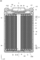
- FIG. 3 is a cross-sectional view showing one example of the cross-sectional structure of the electrode winding body shown in FIG.
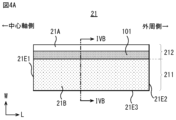
- FIG. 4A is a development view of the positive electrode shown in FIG.
- FIG. 4B is a cross-sectional view of the positive electrode shown in FIG.
- FIG. 5A is a development view of the negative electrode shown in FIG.
- FIG. 5B is a cross-sectional view of the negative electrode shown in FIG.
- FIG. 6 is an enlarged plan view showing a part of the laminate shown in FIG. FIG.
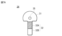
- FIG. 7A is a plan view of the positive electrode current collector plate shown in FIG.
- FIG. 7B is a plan view of the negative electrode current collector plate shown in FIG.
- FIG. 8 is a perspective view illustrating a manufacturing process of the secondary battery shown in FIG.
- FIG. 9 is a block diagram showing a circuit configuration of a battery pack to which the secondary battery according to one embodiment of the present disclosure is applied.
- FIG. 10 is an enlarged plan view showing a part of the laminate of Comparative Example 1. As shown in FIG.
- the applicant has therefore developed a secondary battery with a so-called tabless structure, which does not use electrode terminals (tabs) connected to the positive and negative electrodes of the battery element (see, for example, the above-mentioned Patent Document 1).
- this tabless structure secondary battery, instead of using positive and negative tabs, a positive current collector plate and a negative current collector plate are used, and the positive and negative current collector plates are connected to the positive and negative electrodes of the battery element with a larger contact surface. Therefore, compared to a secondary battery with a tab structure, the internal resistance is very small, making it possible to charge and discharge with a relatively large current.
- secondary batteries with a tabless structure have the advantage that their internal resistance is much smaller than that of secondary batteries with a tab structure, making it possible to suppress the rise in battery temperature during charging at a high load rate.
- the widthwise end of the positive electrode is folded to form a joining surface (first end surface) for joining to the positive electrode current collector plate
- the widthwise end of the negative electrode is folded to form a joining surface (second end surface) for joining to the negative electrode current collector plate.
- the negative electrode active material layer is subjected to stress, particularly at the widthwise end of the negative electrode. Therefore, the applicant has further investigated the matter and has come to propose a secondary battery with a tabless structure that can alleviate the stress applied to the negative electrode active material layer when the second end surface is formed. This secondary battery will be described in detail below.
- a cylindrical lithium ion secondary battery having a cylindrical exterior shape will be described as an example.
- the secondary battery disclosed herein is not limited to a cylindrical lithium ion secondary battery, and may be a lithium ion secondary battery having an exterior shape other than cylindrical, or may be a battery using an electrode reactant other than lithium.
- the principle of charging and discharging a secondary battery is not particularly limited, but below, a case will be described in which battery capacity is obtained by utilizing the absorption and release of electrode reactants.
- This secondary battery has a positive electrode, a negative electrode, and an electrolyte.
- the charge capacity of the negative electrode is larger than the discharge capacity of the positive electrode.
- the electrochemical capacity per unit area of the negative electrode is set to be larger than the electrochemical capacity per unit area of the positive electrode.
- the type of electrode reactant is not particularly limited, but specifically, it is a light metal such as an alkali metal or an alkaline earth metal.
- Alkaline metals include lithium, sodium, and potassium, while alkaline earth metals include beryllium, magnesium, and calcium.
- the electrode reactant is lithium.
- a secondary battery that obtains battery capacity by utilizing the absorption and release of lithium is known as a lithium-ion secondary battery.
- lithium-ion secondary battery lithium is absorbed and released in an ionic state.
- Fig. 1 shows a cross-sectional structure along the height direction of a lithium-ion secondary battery 1 (hereinafter simply referred to as secondary battery 1) according to the present embodiment.
- secondary battery 1 shown in Fig. 1, an electrode winding body 20 serving as a battery element is housed inside a cylindrical outer can 11.
- the secondary battery 1 includes, for example, a pair of insulating plates 12, 13, an electrode winding body 20, a positive electrode current collector 24, and a negative electrode current collector 25 inside an outer can 11.
- the electrode winding body 20 is, for example, a structure in which a positive electrode 21 and a negative electrode 22 are stacked and wound with a separator 23 interposed therebetween.
- the electrode winding body 20 is impregnated with an electrolyte solution, which is a liquid electrolyte.
- the secondary battery 1 may further include, inside the outer can 11, one or more of a positive temperature coefficient (PTC) element and a reinforcing member.
- PTC positive temperature coefficient
- the outer can 11 has a hollow cylindrical structure with a closed lower end and an open upper end in the Z-axis direction, which is the height direction. Therefore, the upper end of the outer can 11 is an open end 11N.
- the material of the outer can 11 includes, for example, a metal material such as iron. However, the surface of the outer can 11 may be plated with a metal material such as nickel.
- the insulating plate 12 and the insulating plate 13 are disposed, for example, facing each other in the Z-axis direction with the electrode winding body 20 sandwiched therebetween.
- the open end 11N and its vicinity are sometimes referred to as the upper part of the secondary battery 1
- the part where the outer can 11 is closed and its vicinity are sometimes referred to as the lower part of the secondary battery 1.
- Each of the insulating plates 12 and 13 is, for example, a dish-shaped plate having a surface perpendicular to the central axis CL of the electrode winding body 20, i.e., a surface perpendicular to the Z-axis in Fig. 1.
- the insulating plates 12 and 13 are arranged so as to sandwich the electrode winding body 20 therebetween.
- the battery lid 14 seals the exterior can 11 with the electrode winding body 20 and the like housed inside the exterior can 11.
- the crimped structure 11R is a so-called crimp structure, and has a bent portion 11P as a so-called crimp portion.
- the battery lid 14 is a closing member that mainly closes the open end 11N when the electrode winding body 20 and the like are housed inside the exterior can 11.
- the battery lid 14 contains, for example, the same material as the material from which the exterior can 11 is formed.
- the central region of the battery lid 14 protrudes upward (in the +Z direction), for example.
- the peripheral region of the battery lid 14 other than the central region is in contact with, for example, the safety valve mechanism 30.
- the gasket 15 is a sealing member that is mainly interposed between the folded portion 11P of the outer can 11 and the battery lid 14.
- the gasket 15 seals the gap between the folded portion 11P and the battery lid 14.
- the surface of the gasket 15 may be coated with, for example, asphalt.
- the gasket 15 contains, for example, one or more types of insulating materials.
- the type of insulating material is not particularly limited, but may be, for example, a polymer material such as polybutylene terephthalate (PBT) and polypropylene (PP). Among them, the insulating material is preferably polybutylene terephthalate. This is because the gap between the folded portion 11P and the battery lid 14 is sufficiently sealed while electrically isolating the outer can 11 and the battery lid 14 from each other.
- the safety valve mechanism 30 is mainly configured to release the internal pressure by releasing the sealed state of the outer can 11 as necessary when the pressure (internal pressure) inside the outer can 11 increases.
- the internal pressure of the outer can 11 increases due to, for example, gas generated due to a decomposition reaction of the electrolyte during charging and discharging.
- the internal pressure of the outer can 11 may also increase due to heating from the outside.
- the electrode winding body 20 is a power generating element that causes charge/discharge reactions to proceed, and is housed inside the exterior can 11.
- the electrode winding body 20 includes a positive electrode 21, a negative electrode 22, a separator 23, and an electrolytic solution that is a liquid electrolyte.
- the electrode winding body 20 is a development view of the electrode winding body 20, and is a schematic representation of a part of the laminate S20 including the positive electrode 21, the negative electrode 22, and the separator 23.
- the positive electrode 21 and the negative electrode 22 are laminated with the separator 23 interposed therebetween.
- the separator 23 has, for example, two base materials, that is, the first separator member 23A and the second separator member 23B. Therefore, the electrode winding body 20 has a four-layer laminate S20 in which the positive electrode 21, the first separator member 23A, the negative electrode 22, and the second separator member 23B are laminated in this order.
- the positive electrode 21, the first separator member 23A, the negative electrode 22, and the second separator member 23B are all approximately strip-shaped members with the W-axis direction as the short side direction and the L-axis direction as the long side direction.
- the electrode winding body 20 is formed by winding the laminate S20 around a central axis CL extending in the Z-axis direction so that the laminate S20 forms a spiral shape in a horizontal cross section perpendicular to the Z-axis direction. At this time, the laminate S20 is wound in a position in which the W-axis direction is approximately aligned with the Z-axis direction.
- FIG. 3 shows an example of a configuration along a horizontal cross section perpendicular to the Z-axis direction in the electrode winding body 20. However, in FIG. 3, the separator 23 is omitted from the illustration in order to improve visibility.
- the electrode winding body 20 has an overall appearance of a substantially cylindrical shape.
- a through hole 26 is formed in the center of the electrode winding body 20 as an internal space.
- the through hole 26 is a hole for inserting a winding core for assembling the electrode winding body 20 and an electrode rod for welding.
- the positive electrode 21, the negative electrode 22, and the separator 23 are wound so that the separator 23 is disposed at the outermost circumference of the electrode winding body 20 and the innermost circumference of the electrode winding body 20.
- the negative electrode 22 is disposed outside the positive electrode 21 at the outermost circumference of the electrode winding body 20. That is, as shown in FIG. 3, the positive electrode outermost portion 21out located at the outermost circumference of the positive electrode 21 included in the electrode winding body 20 is disposed inside the negative electrode outermost portion 22out located at the outermost circumference of the negative electrode 22 included in the electrode winding body 20.
- the positive electrode outermost portion 21out is the outermost portion of the positive electrode 21 in the electrode winding body 20 for one revolution.
- the negative electrode outermost portion 22out is the outermost portion of the negative electrode 22 in the electrode winding body 20 for one revolution.
- the negative electrode 22 is disposed inside the positive electrode 21 at the innermost circumference of the electrode winding body 20. That is, as shown in FIG. 3, the negative electrode innermost portion 22in located at the innermost circumference of the negative electrode 22 included in the electrode winding body 20 is located inside the positive electrode innermost portion 21in located at the innermost circumference of the positive electrode 21 included in the electrode winding body 20.
- the positive electrode innermost portion 21in is the innermost portion of the positive electrode 21 in the electrode winding body 20.
- the negative electrode innermost portion 22in is the innermost portion of the negative electrode 22 in the electrode winding body 20.
- the number of turns of each of the positive electrode 21, the negative electrode 22, and the separator 23 is not particularly limited and can be set arbitrarily.
- FIG. 4A is an exploded view of the positive electrode 21, and is a schematic representation of the state before being wound.
- FIG. 4B shows the cross-sectional configuration of the positive electrode 21. Note that FIG. 4B shows a cross section taken along line IVB-IVB shown in FIG. 4A.
- the positive electrode 21 includes, for example, a positive electrode collector 21A and a positive electrode active material layer 21B provided on the positive electrode collector 21A.
- the positive electrode active material layer 21B may be provided on only one side of the positive electrode collector 21A, or on both sides of the positive electrode collector 21A.
- FIG. 4B shows the case where the positive electrode active material layer 21B is provided on both sides of the positive electrode collector 21A.
- the positive electrode current collector 21A includes a positive electrode current collector inner peripheral surface 21A1 facing the winding center side of the electrode winding body 20, i.e., the central axis CL, and a positive electrode current collector outer peripheral surface 21A2 facing the opposite side of the winding center side of the electrode winding body 20, i.e., the opposite side of the positive electrode current collector inner peripheral surface 21A1.
- the positive electrode 21 has, as the positive electrode active material layer 21B, a positive electrode inner peripheral side active material layer 21B1 covering at least a part of the positive electrode current collector inner peripheral surface 21A1, and a positive electrode outer peripheral side active material layer 21B2 covering at least a part of the positive electrode current collector outer peripheral surface 21A2.
- the positive electrode inner peripheral side active material layer 21B1 and the positive electrode outer peripheral side active material layer 21B2 may be collectively referred to as the positive electrode active material layer 21B without distinguishing between them.
- the positive electrode 21 has a positive electrode covering portion 211 in which the positive electrode collector 21A is covered with a positive electrode active material layer 21B, and a positive electrode exposed portion 212 in which the positive electrode collector 21A is exposed without being covered with the positive electrode active material layer 21B.
- the positive electrode covering portion 211 and the positive electrode exposed portion 212 each extend along the L-axis direction, which is the longitudinal direction of the positive electrode 21, from the central axis side edge 21E1 of the positive electrode 21 to the outer peripheral edge 21E2 of the positive electrode 21.
- the L-axis direction corresponds to the winding direction of the electrode winding body 20.
- the positive electrode collector 21A is covered with the positive electrode active material layer 21B from the central axis side edge 21E1 of the positive electrode 21 to the outer peripheral edge 21E2 of the positive electrode 21 in the winding direction of the electrode winding body 20.
- the positive electrode covering portion 211 and the positive electrode exposed portion 212 are adjacent to each other in the W-axis direction, which is the short side direction of the positive electrode 21.
- the W-axis direction substantially coincides with the central axis CL. As shown in FIG.
- the central axis side edge 21E1 of the positive electrode innermost circumferential portion 21in is located in a position receding inward from the central axis side edge 22E1 of the negative electrode innermost circumferential portion 22in.
- the positive electrode 21 further has a lower edge 21E3 extending in the L-axis direction at the lower side of the electrode winding body 20.
- An insulating layer 101 may be provided near the boundary between the positive electrode covering portion 211 and the positive electrode exposed portion 212.
- the insulating layer 101 may extend from the central axis side edge 21E1 to the outer peripheral side edge 21E2 of the electrode winding body 20, similar to the positive electrode covering portion 211 and the positive electrode exposed portion 212.
- the insulating layer 101 may be bonded to at least one of the first separator member 23A and the second separator member 23B. This is because it is possible to prevent the occurrence of misalignment between the positive electrode 21 and the separator 23.
- the insulating layer 101 may include a resin containing polyvinylidene fluoride (PVDF). By containing PVDF, the insulating layer 101 may swell due to, for example, a solvent contained in the electrolyte, and may be well bonded to the separator 23. The detailed configuration of the positive electrode 21 will be described later.
- FIG. 5A is an exploded view of the negative electrode 22, and is a schematic representation of the state before being wound.
- FIG. 5B shows the cross-sectional configuration of the negative electrode 22. Note that FIG. 5B shows a cross section taken along line VB-VB shown in FIG. 5A.
- the negative electrode 22 includes, for example, a negative electrode collector 22A and a negative electrode active material layer 22B provided on the negative electrode collector 22A.
- the negative electrode active material layer 22B may be provided on only one side of the negative electrode collector 22A, or on both sides of the negative electrode collector 22A.
- FIG. 5B shows the case where the negative electrode active material layer 22B is provided on both sides of the negative electrode collector 22A.
- the negative electrode current collector 22A includes a negative electrode current collector inner peripheral surface 22A1 facing the winding center side of the electrode winding body 20, i.e., the central axis CL, and a negative electrode current collector outer peripheral surface 22A2 facing the opposite side of the winding center side of the electrode winding body 20, i.e., the opposite side of the negative electrode current collector inner peripheral surface 22A1.
- the negative electrode 22 has, as the negative electrode active material layer 22B, a negative electrode inner peripheral side active material layer 22B1 covering at least a part of the negative electrode current collector inner peripheral surface 22A1, and a negative electrode outer peripheral side active material layer 22B2 covering at least a part of the negative electrode current collector outer peripheral surface 22A2.
- the negative electrode inner peripheral side active material layer 22B1 and the negative electrode outer peripheral side active material layer 22B2 may be collectively referred to as the negative electrode active material layer 22B without distinguishing between them.
- the negative electrode 22 has a negative electrode covering portion 221 in which the negative electrode collector 22A is covered with the negative electrode active material layer 22B, and a negative electrode exposed portion 222 in which the negative electrode collector 22A is exposed without being covered with the negative electrode active material layer 22B.
- the negative electrode covering portion 221 and the negative electrode exposed portion 222 each extend along the L-axis direction, which is the longitudinal direction of the negative electrode 22.
- the negative electrode exposed portion 222 extends from the central axis side edge 22E1 to the outer peripheral edge 22E2 of the negative electrode 22 in the winding direction of the electrode winding body 20.
- the negative electrode covering portion 221 is not provided on the central axis side edge 22E1 and the outer peripheral edge 22E2 of the negative electrode 22.
- a part of the negative electrode exposed portion 222 is formed so as to sandwich the negative electrode covering portion 221 in the L-axis direction, which is the longitudinal direction of the negative electrode 22.
- the negative electrode exposed portion 222 includes a first portion 222A, a second portion 222B, and a third portion 222C.
- the negative electrode 22 further has a lower edge 22E3 extending in the L-axis direction at the lower side of the electrode winding body 20.
- the first portion 222A is provided adjacent to the negative electrode covering portion 221 in the W-axis direction, and extends in the L-axis direction from the central axis side edge 22E1 to the outer periphery side edge 22E2 of the negative electrode 22.
- the second portion 222B and the third portion 222C are provided to sandwich the negative electrode covering portion 221 in the L-axis direction.
- the first portion 222A is located near the lower edge 22E3 of the negative electrode 22.
- the second portion 222B is located, for example, near the central axis side edge 22E1 of the negative electrode 22, and the third portion 222C is located near the outer periphery side edge 22E2 of the negative electrode 22.
- the negative electrode current collector 22A is shown as extending linearly along the W-axis direction. However, in reality, the negative electrode edge 222E of the negative electrode exposed portion 222 is bent toward the central axis CL as shown in FIG. 1 and connected to the negative electrode current collector 25. The detailed configuration of the negative electrode 22 will be described later.
- the positive electrode 21 and the negative electrode 22 are laminated via the separator 23 so that the positive electrode exposed portion 212 and the first portion 222A of the negative electrode exposed portion 222 are oriented in opposite directions along the W-axis direction, which is the width direction.
- the end of the separator 23 of the electrode winding body 20 is fixed by attaching a fixing tape 46 to the side portion 45, so that the winding does not become loose.
- the width of the positive electrode exposed portion 212 is A and the width of the first portion 222A of the negative electrode exposed portion 222 is B
- C the width of the portion of the positive electrode exposed portion 212 that protrudes from the outer edge of the separator 23 in the width direction
- D the length of the first portion 222A of the negative electrode exposed portion 222 that protrudes from the outer edge of the separator 23 on the opposite side in the width direction
- the width D 3 (mm).
- a plurality of adjacent positive electrode edges 212E in the radial direction (R direction) of the electrode winding body 20 are bent toward the central axis CL so as to overlap with each other, forming the upper end surface 41 of the electrode winding body 20.
- a plurality of adjacent negative electrode edges 222E in the radial direction (R direction) are bent toward the central axis CL so as to overlap with each other, forming the lower end surface 42 of the electrode winding body 20.
- the plurality of positive electrode edges 212E of the positive electrode exposed portion 212 are gathered at the upper end surface 41 of the electrode winding body 20, and the plurality of negative electrode edges 222E of the negative electrode exposed portion 222 are gathered at the lower end surface 42 of the electrode winding body 20.
- the positive electrode edge 212E is bent toward the central axis CL to have a flat surface.
- the negative electrode edge 222E is bent toward the central axis CL to have a flat surface.
- the flat surface here does not only mean a completely flat surface, but also includes a surface that has some unevenness or surface roughness to the extent that the positive electrode exposed portion 212 and the negative electrode exposed portion 222 can be joined to the positive electrode current collector 24 and the negative electrode current collector 25, respectively.
- the positive electrode collector 21A is made of, for example, aluminum foil, as described later.
- the negative electrode collector 22A is made of, for example, copper foil, as described later.
- the positive electrode collector 21A is softer than the negative electrode collector 22A. That is, the Young's modulus of the positive electrode exposed portion 212 is lower than that of the negative electrode exposed portion 222. For this reason, in one embodiment, it is more preferable that the widths A to D have a relationship of A>B and C>D.
- the heights measured from the tip of the separator 23 at the folded portions may be approximately the same for the positive electrode 21 and the negative electrode 22.
- the multiple positive electrode edges 212E (FIG. 1) of the positive electrode exposed portion 212 are folded and overlap appropriately. Therefore, the positive electrode exposed portion 212 and the positive electrode collector plate 24 can be easily joined.
- the negative electrode edges 222E (FIG. 1) of the negative electrode exposed portion 222 are folded and overlap each other to a certain extent. This allows the negative electrode exposed portion 222 and the negative electrode current collector plate 25 to be easily joined together.
- the joining here means that they are joined together by, for example, laser welding, but the joining method is not limited to laser welding.
- the portion of the positive electrode exposed portion 212 of the positive electrode 21 that faces the negative electrode 22 across the separator 23 is covered with an insulating layer 101.
- the insulating layer 101 has a width of, for example, 3 mm in the W-axis direction.
- the insulating layer 101 covers the entire area of the positive electrode exposed portion 212 of the positive electrode 21 that faces the negative electrode covering portion 221 of the negative electrode 22 through the separator 23.
- the insulating layer 101 can effectively prevent an internal short circuit of the secondary battery 1 when, for example, a foreign object enters between the negative electrode covering portion 221 and the positive electrode exposed portion 212.
- the insulating layer 101 absorbs the impact and can effectively prevent bending of the positive electrode exposed portion 212 and short circuit between the positive electrode exposed portion 212 and the negative electrode 22.
- FIG. 6 is an enlarged plan view showing a portion of the laminate S20 in the unfolded state of the electrode winding body 20, particularly the vicinity of the central axis side edge 22E1 of the negative electrode 22.
- the positive electrode active material layer 21B is defined by an outline including the first positive electrode edge portion 21BE1 on the lower end face 42 side and the second positive electrode edge portion 21BE2 on the central axis CL side.
- the first positive electrode edge portion 21BE1 extends in the L-axis direction.
- the second positive electrode edge portion 21BE2 extends in the W-axis direction.
- the first positive electrode edge portion 21BE1 coincides with the lower edge 21E3, and the second positive electrode edge portion 21BE2 coincides with the central axis side edge 21E1.
- the first positive electrode edge portion 21BE1 and the second positive electrode edge portion 21BE2 both extend in a straight line.
- first positive electrode edge portion 21BE1 and the second positive electrode edge portion 21BE2 may have a curved shape or may be serpentine.
- the first positive electrode edge portion 21BE1 and the second positive electrode edge portion 21BE2 are connected so as to be perpendicular to each other, for example, at the intersection point P4.
- the negative electrode active material layer 22B is defined by an outline including the first negative electrode edge portion 22BE1 on the lower end surface 42 side, the second negative electrode edge portion 22BE2 on the central axis CL side, and the third negative electrode edge portion 22BE3 connecting the first negative electrode edge portion 22BE1 and the second negative electrode edge portion 22BE2.
- the first negative electrode edge portion 22BE1 extends in the L-axis direction.
- the second negative electrode edge portion 22BE2 extends in the W-axis direction.
- the first negative electrode edge portion 22BE1 and the second negative electrode edge portion 22BE2 both extend linearly.
- the third negative electrode edge portion 22BE3 has a curved shape in the example of FIG. 6.
- the first negative electrode edge portion 22BE1 and the second negative electrode edge portion 22BE2 may have a curved shape or may be serpentine.
- the third negative electrode edge portion 22BE3 may extend in a straight line or may be serpentine.
- the formation area of the negative electrode active material layer 22B is larger than the formation area of the positive electrode active material layer 21B.
- the formation area of the negative electrode active material layer 22B protrudes from the formation area of the positive electrode active material layer 21B in both the L-axis direction and the W-axis direction. Therefore, the first negative electrode edge portion 22BE1 of the negative electrode active material layer 22B is located closer to the lower end surface 42 than the first positive electrode edge portion 21BE1 of the positive electrode active material layer.
- the second negative electrode edge portion 22BE2 of the negative electrode active material layer 22B is located closer to the central axis CL than the second positive electrode edge portion 21BE2 of the positive electrode active material layer.
- the third negative electrode edge 22BE3 passes through a position recessed inward from the intersection point P1 where the extension line of the first negative electrode edge 22BE1 and the extension line of the second negative electrode edge 22BE2 intersect. Furthermore, the intersection point P2 where the first negative electrode edge 22BE1 and the third negative electrode edge 22BE3 intersect is located between the intersection points P1 and P3. The intersection point P3 is the point where the extension line of the first negative electrode edge 22BE1 and the second positive electrode edge 21BE2 intersect.
- the laminate S20 further satisfies the following conditional expression (1). 0.60 ⁇ L2/L1 ⁇ 15.00 ....
- L1 represents the first distance between the intersection point P1 and the intersection point P2
- L2 represents the second distance between the intersection point P2 and the intersection point P3.
- the first distance L1 may be, for example, 0.2 mm or more and 5.0 mm or less.
- the second distance L2 may be, for example, 2 mm or more and 25 mm or less.
- the secondary battery 1 may further have insulating tapes 53, 54 in the gap between the exterior can 11 and the electrode winding body 20.
- the positive electrode exposed portion 212 and the negative electrode exposed portion 222 gathered at the upper end surface 41 and the lower end surface 42 are conductors such as bare metal foil. Therefore, if the positive electrode exposed portion 212 and the negative electrode exposed portion 222 are close to the exterior can 11, a short circuit may occur between the positive electrode 21 and the negative electrode 22 through the exterior can 11.
- the insulating tapes 53, 54 are provided as insulating members.
- the insulating tapes 53, 54 are, for example, adhesive tapes whose base layer is made of any one of polypropylene, polyethylene terephthalate, and polyimide, and whose base layer has an adhesive layer on one side.
- the insulating tapes 53, 54 are positioned so as not to overlap with the fixing tape 46 attached to the side portion 45, and the thickness of the insulating tapes 53, 54 is set to be equal to or less than the thickness of the fixing tape 46.
- the positive electrode current collector 24 is arranged to face the upper end face 41 and the negative electrode current collector 25 is arranged to face the lower end face 42, and the positive electrode covering portion 211 present on the upper end face 41 and the positive electrode current collector 24 are welded at multiple points, and the negative electrode covering portion 221 present on the lower end face 42 and the negative electrode current collector 25 are welded at multiple points.
- the fact that the upper end face 41 and the lower end face 42 are flat as described above also contributes to the reduction in resistance.
- the positive electrode current collector 24 is electrically connected to the battery cover 14, for example, via the safety valve mechanism 30.
- the negative electrode current collector 25 is electrically connected to the exterior can 11, for example. Fig.
- FIG. 7A is a schematic diagram showing an example of the configuration of the positive electrode current collector 24.
- Fig. 7B is a schematic diagram showing an example of the configuration of the negative electrode current collector 25.
- the positive electrode current collector 24 is a metal plate made of, for example, aluminum or an aluminum alloy, or a composite material thereof.
- the negative electrode current collector 25 is a metal plate made of, for example, nickel, a nickel alloy, copper, or a copper alloy, or a composite material of two or more of these.
- the positive electrode current collector 24 has a shape in which a substantially rectangular band-shaped portion 32 is connected to a substantially fan-shaped sector portion 31.
- a through hole 35 is formed near the center of the sector portion 31.
- the positive electrode current collector 24 is provided so that the through hole 35 overlaps with the through hole 26 in the Z-axis direction.
- the portion indicated by diagonal lines in FIG. 7A is the insulating portion 32A of the band-shaped portion 32.
- the insulating portion 32A is a part of the band-shaped portion 32 to which an insulating tape is attached or an insulating material is applied.
- the portion of the band-shaped portion 32 below the insulating portion 32A is the connection portion 32B to the sealing plate, which also serves as an external terminal.
- the band-shaped portion 32 is less likely to come into contact with the portion of the negative electrode potential. Therefore, the positive electrode current collector 24 does not need to have the insulating portion 32A. If the positive electrode current collector 24 does not have an insulating portion 32A, the charge/discharge capacity can be increased by widening the width between the positive electrode 21 and the negative electrode 22 by an amount equivalent to the thickness of the insulating portion 32A.
- the shape of the negative current collector 25 shown in FIG. 7B is almost the same as the shape of the positive current collector 24 shown in FIG. 7A.
- the strip portion 34 of the negative current collector 25 is different from the strip portion 32 of the positive current collector 24.
- the strip portion 34 of the negative current collector 25 is shorter than the strip portion 32 of the positive current collector 24, and does not have a portion corresponding to the insulating portion 32A of the positive current collector 24.
- the strip portion 34 is provided with a round protrusion 37 indicated by multiple circles. During resistance welding, the current is concentrated on the protrusion 37, which melts and welds the strip portion 34 to the bottom of the outer can 11.
- the negative current collector 25 has a through hole 36 formed near the center of the sector portion 33. In the secondary battery 1, the negative current collector 25 is provided so that the through hole 36 overlaps with the through hole 26 in the Z-axis direction.
- the sectorial portion 31 of the positive electrode current collector 24 covers only a portion of the upper end face 41 due to its planar shape.
- the sectorial portion 33 of the negative electrode current collector 25 covers only a portion of the lower end face 42 due to its planar shape.
- the positive electrode current collector 21A contains a conductive material such as aluminum, etc.
- the positive electrode current collector 21A is, for example, a metal foil made of aluminum or an aluminum alloy.
- the positive electrode active material layer 21B contains, as a positive electrode active material, any one or more of positive electrode materials capable of absorbing and releasing lithium. However, the positive electrode active material layer 21B may further contain any one or more of other materials such as a positive electrode binder and a positive electrode conductor.
- the positive electrode material is preferably a lithium-containing compound, more specifically, a lithium-containing composite oxide and a lithium-containing phosphate compound.
- the lithium-containing composite oxide is an oxide containing lithium and one or more other elements, i.e., elements other than lithium, as constituent elements.
- the lithium-containing composite oxide has, for example, any one of a layered rock salt type and a spinel type crystal structure.
- the lithium-containing phosphate compound is a phosphate compound containing lithium and one or more other elements as constituent elements, and has, for example, an olivine type crystal structure.
- the positive electrode active material layer 21B may contain, in particular, at least one of lithium cobalt oxide, lithium nickel cobalt manganese oxide, and lithium nickel cobalt aluminum oxide as a positive electrode active material.
- the positive electrode binder contains, for example, one or more of synthetic rubber and polymer compounds.
- the synthetic rubber is, for example, styrene butadiene rubber, fluorine rubber, and ethylene propylene diene.
- the polymer compound is, for example, polyvinylidene fluoride and polyimide.
- the positive electrode conductive agent contains, for example, one or more of carbon materials.
- the carbon materials are, for example, graphite, carbon black, acetylene black, and ketjen black.
- the positive electrode conductive agent may be a metal material, a conductive polymer, or the like, as long as it is a material having conductivity.
- the negative electrode collector 22A includes a conductive material such as copper.
- the negative electrode collector 22A is a metal foil made of nickel, a nickel alloy, copper, or a copper alloy.
- the surface of the negative electrode collector 22A is preferably roughened. This is because the adhesion of the negative electrode active material layer 22B to the negative electrode collector 22A is improved by the so-called anchor effect. In this case, it is sufficient that the surface of the negative electrode collector 22A is roughened at least in the region facing the negative electrode active material layer 22B.
- the roughening method is, for example, a method of forming fine particles using an electrolytic process.
- Electrolytic copper foil In the electrolytic process, fine particles are formed on the surface of the negative electrode collector 22A by an electrolytic method in an electrolytic bath, so that the surface of the negative electrode collector 22A is provided with unevenness. Copper foil produced by an electrolytic method is generally called electrolytic copper foil.
- the negative electrode active material layer 22B contains, as the negative electrode active material, any one or more of the negative electrode materials capable of absorbing and releasing lithium. However, the negative electrode active material layer 22B may further contain any one or more of the other materials such as a negative electrode binder and a negative electrode conductor.
- the negative electrode material is, for example, a carbon material. This is because a high energy density can be stably obtained because the change in the crystal structure during the absorption and release of lithium is very small. In addition, the carbon material also functions as a negative electrode conductor, so that the conductivity of the negative electrode active material layer 22B is improved.
- the carbon material is, for example, graphitizable carbon, non-graphitizable carbon, graphite, etc.
- the plane spacing of the (002) plane in the non-graphitizable carbon is preferably 0.37 nm or more.
- the plane spacing of the (002) plane in the graphite is preferably 0.34 nm or less.
- the carbon material is, for example, pyrolytic carbon, cokes, glassy carbon fiber, organic polymer compound calcined body, activated carbon, and carbon black.
- the cokes include pitch coke, needle coke, and petroleum coke.
- the organic polymer compound calcined body is a product of calcining (carbonizing) a polymer compound such as a phenolic resin and a furan resin at an appropriate temperature.
- the carbon material may be low-crystalline carbon heat-treated at a temperature of about 1000° C. or less, or amorphous carbon.
- the shape of the carbon material may be any of fibrous, spherical, granular, and scaly.
- the negative electrode active material layer 22B may contain a silicon-containing material containing at least one of silicon, silicon oxide, carbon silicon compound, and silicon alloy as the negative electrode active material.
- the silicon-containing material is a general term for materials containing silicon as a constituent element. However, the silicon-containing material may contain only silicon as a constituent element.
- the type of silicon-containing material may be only one type or two or more types.
- the silicon-containing material can form an alloy with lithium, and may be a simple substance of silicon, a silicon alloy, a silicon compound, a mixture of two or more types thereof, or a material containing one or more types of phases thereof.
- the silicon-containing material may be crystalline or amorphous, or may contain both a crystalline portion and an amorphous portion.
- the simple substance described here means a general simple substance, and may contain a trace amount of impurities. In other words, the purity of the simple substance is not necessarily limited to 100%.
- the silicon alloy contains, for example, one or more of tin, nickel, copper, iron, cobalt, manganese, zinc, indium, silver, titanium, germanium, bismuth, antimony, and chromium as a constituent element other than silicon.
- the silicon compound contains, for example, one or more of carbon and oxygen as a constituent element other than silicon.
- the silicon compound may contain, for example, one or more of the series of constituent elements described for the silicon alloy as a constituent element other than silicon.
- examples of silicon alloys and silicon compounds include SiB4 , SiB6 , Mg2Si , Ni2Si, TiSi2 , MoSi2 , CoSi2 , NiSi2 , CaSi2 , CrSi2 , Cu5Si , FeSi2, MnSi2 , NbSi2 , TaSi2 , VSi2 , WSi2 , ZnSi2 , SiC , Si3N4 , Si2N2O , and SiOv (0 ⁇ v ⁇ 2 ), etc.
- the range of v can be set arbitrarily, and may be, for example, 0.2 ⁇ v ⁇ 1.4.
- the separator 23 is interposed between the positive electrode 21 and the negative electrode 22.
- the separator 23 allows lithium ions to pass while preventing short circuit of current caused by contact between the positive electrode 21 and the negative electrode 22.
- the separator 23 is, for example, one or more types of porous membranes such as synthetic resins and ceramics, and may be a laminated membrane of two or more types of porous membranes.
- the synthetic resin is, for example, polytetrafluoroethylene, polypropylene, and polyethylene.
- the separator 23 may have a base material made of a single-layer polyolefin porous membrane containing polyethylene. This is because good high-output characteristics can be obtained compared to a laminated membrane.
- the thickness of the porous membrane may be, for example, 10 ⁇ m or more and 15 ⁇ m or less.
- the thickness of the single-layered porous film made of polyolefin is 15 ⁇ m or less, better discharge capacity characteristics can be obtained.
- the surface density of the porous film may be, for example, 6.3 g/m 2 or more and 8.3 g/m 2 or less.
- the surface density of the single-layered porous film made of polyolefin is 6.3 g/m 2 or more, internal short circuit can be sufficiently avoided. If the surface density of the single-layered porous film made of polyolefin is 8.3 g/m 2 or less, better discharge capacity characteristics can be obtained.
- the separator 23 may include, for example, the porous film as the substrate described above and a polymer compound layer provided on one or both sides of the substrate layer. This is because the adhesiveness of the separator 23 to each of the positive electrode 21 and the negative electrode 22 is improved, thereby suppressing distortion of the electrode winding body 20. This suppresses the decomposition reaction of the electrolyte and also suppresses leakage of the electrolyte impregnated in the substrate layer, so that the resistance is less likely to increase even when charging and discharging is repeated, and battery swelling is suppressed.
- the polymer compound layer includes, for example, a polymer compound such as polyvinylidene fluoride. This is because it has excellent physical strength and is electrochemically stable.
- the polymer compound may be other than polyvinylidene fluoride.
- a solution in which a polymer compound is dissolved in an organic solvent or the like is applied to the substrate layer, and then the substrate layer is dried. Note that the substrate layer may be immersed in the solution and then dried.
- This polymer compound layer may contain, for example, one or more types of insulating particles such as inorganic particles. Types of inorganic particles include, for example, aluminum oxide and aluminum nitride.
- the electrolyte contains a solvent and an electrolyte salt. However, the electrolyte may further contain any one or more of other materials such as additives.
- the solvent contains any one or more of non-aqueous solvents such as organic solvents.
- the electrolyte containing a non-aqueous solvent is a so-called non-aqueous electrolyte.
- the non-aqueous solvent contains, for example, a fluorine compound and a dinitrile compound.
- the fluorine compound contains, for example, at least one of fluorinated ethylene carbonate, trifluorocarbonate, trifluoroethyl methyl carbonate, fluorinated carboxylic acid ester, and fluorine ether.
- the non-aqueous solvent may further contain at least one of nitrile compounds other than the dinitrile compound, such as a mononitrile compound or a trinitrile compound.
- nitrile compounds other than the dinitrile compound such as a mononitrile compound or a trinitrile compound.
- the dinitrile compound for example, succinonitrile (SN) is preferable.
- SN succinonitrile
- the dinitrile compound is not limited to succinonitrile, and may be other dinitrile compounds such as adiponitrile.
- the electrolyte salt includes, for example, one or more of salts such as lithium salts.
- the electrolyte salt may include, for example, a salt other than lithium salt.
- the salt other than lithium is, for example, a salt of a light metal other than lithium.
- the lithium salt is, for example, lithium hexafluorophosphate (LiPF 6 ), lithium tetrafluoroborate (LiBF 4 ), lithium perchlorate (LiClO 4 ), lithium hexafluoroarsenate (LiAsF 6 ), lithium tetraphenylborate (LiB(C 6 H 5 ) 4 ), lithium methanesulfonate (LiCH 3 SO 3 ), lithium trifluoromethanesulfonate (LiCF 3 SO 3 ), lithium tetrachloroaluminate (LiAlCl 4 ), dilithium hexafluorosilicate (Li 2 SF 6 ), lithium chloride (LiCl), lithium bromide (LiBr), etc.
- LiPF 6 lithium hexafluorophosphate
- LiBF 4 lithium perchlorate
- LiAsF 6 lithium hexafluoroarsenate
- any one or more of lithium hexafluorophosphate, lithium tetrafluoroborate, lithium perchlorate, and lithium hexafluoroarsenate are preferred, and lithium hexafluorophosphate is more preferred.
- the content of the electrolyte salt is not particularly limited, but is preferably 0.3 mol/kg to 3 mol/kg relative to the solvent.
- the concentration of LiPF 6 in the electrolyte is preferably 1.25 mol/kg or more and 1.45 mol/kg or less. This is because cycle deterioration due to consumption (decomposition) of salt during high-load rate charging can be prevented, and high-load cycle characteristics are improved.
- the concentration of LiBF 4 in the electrolyte is preferably 0.001 (wt%) or more and 0.1 (wt%) or less. This is because cycle deterioration due to consumption (decomposition) of salt during high-load rate charging can be more effectively prevented, and high-load cycle characteristics are further improved.
- lithium ions are released from the positive electrode 21 and are absorbed into the negative electrode 22 via the electrolyte.
- lithium ions are released from the negative electrode 22 and are absorbed into the positive electrode 21 via the electrolyte.
- FIG. 8 is a perspective view for explaining the manufacturing process of the secondary battery shown in Fig. 1.
- a positive electrode collector 21A is prepared, and a positive electrode active material layer 21B is selectively formed on the surface of the positive electrode collector 21A to form a positive electrode 21 having a positive electrode coating portion 211 and a positive electrode exposed portion 212.
- a negative electrode collector 22A is prepared, and a negative electrode active material layer 22B is selectively formed on the surface of the negative electrode collector 22A to form a negative electrode 22 having a negative electrode coating portion 221 and a negative electrode exposed portion 222.
- a drying process may be performed on the positive electrode 21 and the negative electrode 22.
- the positive electrode 21 and the negative electrode 22 are stacked via the first separator member 23A and the second separator member 23B so that the positive electrode exposed portion 212 and the first portion 222A of the negative electrode exposed portion 222 are opposite each other in the W-axis direction, to produce a laminate S20.
- the central axis side end of the first separator member 23A and the central axis side end of the second separator member are folded back so that the central axis side ends are sandwiched between the central axis side edge 21E1 of the positive electrode 21 and the negative electrode 22.
- the laminate S20 is spirally wound so that the through holes 26 are formed.
- a fixing tape 46 is attached to the outermost circumference of the spirally wound laminate S20. In this way, the electrode roll 20 is obtained as shown in FIG. 8A.
- the edge of a flat plate having a thickness of, for example, 0.5 mm is pressed perpendicularly, i.e., in the Z-axis direction, against the upper end face 41 and the lower end face 42 of the electrode winding body 20, thereby locally bending a part of the upper end face 41 and a part of the lower end face 42.
- grooves 43 are created that extend radially from the through holes 26 in the radial direction (R direction). Note that the number and arrangement of grooves 43 shown in FIG. 8B are examples and the present disclosure is not limited thereto.
- substantially the same pressure is applied from above and below the electrode winding body 20 in a substantially vertical direction to the upper end face 41 and the lower end face 42 at substantially the same time.
- a rod-shaped jig is inserted into the through hole 26.
- the positive electrode exposed portion 212 and the first part 222A of the negative electrode exposed portion 222 are bent so that the upper end face 41 and the lower end face 42 are flat.
- the positive electrode edge portion 212E of the positive electrode exposed portion 212 and the negative electrode edge portion 222E of the negative electrode exposed portion 222 at the upper end face 41 and the lower end face 42 are bent while overlapping toward the through hole 26.
- the sector portion 31 of the positive electrode current collector 24 is joined to the upper end face 41 by laser welding or the like, and the sector portion 33 of the negative electrode current collector 25 is joined to the lower end face 42 by laser welding or the like.
- insulating tapes 53, 54 are attached to predetermined positions of the electrode winding body 20. After that, as shown in FIG. 8 (D), the strip portion 32 of the positive electrode current collector 24 is folded and the strip portion 32 is inserted into the hole 12H of the insulating plate 12. In addition, the strip portion 34 of the negative electrode current collector 25 is folded and the strip portion 34 is inserted into the hole 13H of the insulating plate 13.
- the electrode winding body 20 assembled as described above is inserted into the exterior can 11 shown in FIG. 8(E), and the bottom of the exterior can 11 is welded to the negative electrode current collector 25. Then, a narrowed portion 11S is formed near the open end 11N of the exterior can 11. Furthermore, electrolyte is injected into the exterior can 11, and the strip portion 32 of the positive electrode current collector 24 is welded to the safety valve mechanism 30.
- the gasket 15, the safety valve mechanism 30, and the battery cover 14 are used to seal the narrowed portion 11S.
- the negative electrode active material layer 22B in a state where the electrode winding body 20 is unfolded, includes the first negative electrode edge portion 22BE1, the second negative electrode edge portion 22BE2, and the third negative electrode edge portion 22BE3.
- the third negative electrode edge portion 22BE3 is located in a position retreated inward from the intersection point P1 where the extension line of the first negative electrode edge portion 22BE1 and the extension line of the second negative electrode edge portion 22BE2 intersect. For this reason, when the first portion 222A of the negative electrode exposed portion 222 is folded to form the lower end surface 42, the negative electrode active material layer 22B is unlikely to peel off or fall off from the negative electrode current collector 22A.
- first negative electrode edge portion 22BE1 and the second negative electrode edge portion 22BE2 form a corner portion where they perpendicularly intersect
- stress is concentrated at the corner portion when the first portion 222A of the negative electrode exposed portion 222 is folded.
- the first negative electrode edge 22BE1 and the second negative electrode edge 22BE2 are connected to each other by the third negative electrode edge 22BE3 that intersects obliquely with both the first negative electrode edge 22BE1 and the second negative electrode edge 22BE2 that are perpendicular to each other.
- Battery pack] 9 is a block diagram showing an example of a circuit configuration in which a battery according to an embodiment of the present invention (hereinafter, referred to as a secondary battery) is applied to a battery pack 300.
- the battery pack 300 includes a battery pack 301, an exterior, a switch unit 304 including a charge control switch 302a and a discharge control switch 303a, a current detection resistor 307, a temperature detection element 308, and a control unit 310.
- the battery pack 300 has a positive terminal 321 and a negative terminal 322, and when charging, the positive terminal 321 and the negative terminal 322 are connected to the positive terminal and the negative terminal of the charger, respectively, and charging is performed. When the electronic device is in use, the positive terminal 321 and the negative terminal 322 are connected to the positive terminal and the negative terminal of the electronic device, respectively, and discharging is performed.
- the battery pack 301 is made up of multiple secondary batteries 301a connected in series or parallel.
- the secondary batteries 1 described above can be used as the secondary batteries 301a.
- FIG. 9 shows an example in which six secondary batteries 301a are connected in 2 parallel and 3 series (2P3S), any other connection method may be used, such as n parallel and m series (n and m are integers).
- the switch unit 304 includes a charge control switch 302a and a diode 302b, as well as a discharge control switch 303a and a diode 303b, and is controlled by the control unit 310.
- the diode 302b has a polarity in the reverse direction to the charge current flowing from the positive terminal 321 to the battery pack 301, and a polarity in the forward direction to the discharge current flowing from the negative terminal 322 to the battery pack 301.
- the diode 303b has a polarity in the forward direction to the charge current and a polarity in the reverse direction to the discharge current. Note that although the switch unit 304 is provided on the + side in FIG. 10, it may be provided on the - side.
- the charge control switch 302a is controlled by the charge/discharge control unit so that it is turned off when the battery voltage reaches the overcharge detection voltage and so that no charging current flows in the current path of the assembled battery 301. After the charge control switch 302a is turned off, only discharging is possible through the diode 302b. In addition, it is controlled by the control unit 310 so that it is turned off when a large current flows during charging and so that the charging current flows in the current path of the assembled battery 301 is cut off.
- the discharge control switch 303a is controlled by the control unit 310 so that it is turned off when the battery voltage reaches the overdischarge detection voltage and so that no discharging current flows in the current path of the assembled battery 301.
- the discharge control switch 303a After the discharge control switch 303a is turned off, only charging is possible through the diode 303b. In addition, it is controlled by the control unit 310 so that it is turned off when a large current flows during discharging and so that the discharging current flows in the current path of the assembled battery 301 is cut off.
- the temperature detection element 308 is, for example, a thermistor that is provided near the battery pack 301 and measures the temperature of the battery pack 301 and supplies the measured temperature to the control unit 310.
- the voltage detection unit 311 measures the voltage of the battery pack 301 and each of the secondary batteries 301a that make it up, A/D converts the measured voltage, and supplies it to the control unit 310.
- the current measurement unit 313 measures the current using a current detection resistor 307, and supplies this measured current to the control unit 310.
- the switch control unit 314 controls the charge control switch 302a and the discharge control switch 303a of the switch unit 304 based on the voltage and current input from the voltage detection unit 311 and the current measurement unit 313.
- the switch control unit 314 sends a control signal to the switch unit 304 to prevent overcharging, overdischarging, and overcurrent charging and discharging.
- the overcharge detection voltage is set to, for example, 4.20V ⁇ 0.05V
- the overdischarge detection voltage is set to, for example, 2.4V ⁇ 0.1V.
- the charge and discharge switches can be semiconductor switches such as MOSFETs.
- the parasitic diodes of the MOSFETs function as diodes 302b and 303b.
- switch control section 314 supplies control signals DO and CO to the gates of charge control switch 302a and discharge control switch 303a, respectively.
- charge control switch 302a and discharge control switch 303a are P-channel types, they are turned ON by a gate potential that is lower than the source potential by a predetermined value or more. That is, in normal charge and discharge operations, control signals CO and DO are at a low level, and charge control switch 302a and discharge control switch 303a are turned ON.
- control signals CO and DO are set to a high level, and the charge control switch 302a and the discharge control switch 303a are set to the OFF state.
- Memory 317 is made up of RAM or ROM, such as non-volatile memory such as EPROM (Erasable Programmable Read Only Memory). Numerical values calculated by control unit 310 and the internal resistance value of each secondary battery 301a in its initial state measured during the manufacturing process are stored in memory 317 in advance, and can also be rewritten as appropriate. In addition, by storing the fully charged capacity of secondary battery 301a, it is possible to calculate, for example, the remaining capacity together with control unit 310.
- the temperature detection unit 318 measures the temperature using the temperature detection element 308, and performs charge/discharge control in the event of abnormal heat generation, and performs corrections when calculating the remaining capacity.
- the secondary battery according to the embodiment of the present disclosure described above can be mounted on devices such as electronic devices, electric vehicles, electric aircraft, and power storage devices, or can be used to supply power.
- Electronic devices include, for example, notebook computers, smartphones, tablet devices, PDAs (personal digital assistants), mobile phones, wearable devices, cordless phone handsets, video movie players, digital still cameras, e-books, electronic dictionaries, music players, radios, headphones, game consoles, navigation systems, memory cards, pacemakers, hearing aids, power tools, electric shavers, refrigerators, air conditioners, televisions, stereos, hot water heaters, microwave ovens, dishwashers, washing machines, dryers, lighting equipment, toys, medical equipment, robots, road conditioners, and traffic lights.
- PDAs personal digital assistants
- mobile phones wearable devices
- cordless phone handsets video movie players
- digital still cameras digital still cameras
- e-books electronic dictionaries
- music players radios
- headphones game consoles
- navigation systems memory cards
- pacemakers hearing aids
- power tools electric shavers, refrigerators, air conditioners, televisions, stereos, hot water heaters, microwave ovens, dishwashers, washing machines, dryers, lighting equipment, toys, medical equipment
- examples of electric vehicles include railroad cars, golf carts, electric carts, and electric cars (including hybrid cars), and the device is used as a driving power source or auxiliary power source for these vehicles.
- Examples of power storage devices include power storage sources for buildings such as homes, or for power generation facilities.
- Example 1 As described below, a cylindrical secondary battery 1 shown in Fig. 1 was fabricated, and its battery characteristics were evaluated. Here, a lithium ion secondary battery having dimensions of 21 mm in diameter and 70 mm in length was fabricated.
- an aluminum foil having a thickness of 12 ⁇ m was prepared as the positive electrode collector 21A.
- a layered lithium oxide having a Ni ratio of 85% or more in lithium nickel cobalt aluminum oxide (NCA) as a positive electrode active material, a positive electrode binder made of polyvinylidene fluoride, and a conductive assistant containing carbon black, acetylene black, and ketjen black were mixed to obtain a positive electrode mixture.
- the mixing ratio of the positive electrode active material, the positive electrode binder, and the conductive assistant was 96.4:2:1.6.
- the positive electrode mixture was added to an organic solvent (N-methyl-2-pyrrolidone), and the organic solvent was stirred to prepare a paste-like positive electrode mixture slurry.
- the positive electrode mixture slurry was applied to predetermined areas on both sides of the positive electrode collector 21A using a coating device, and then the positive electrode mixture slurry was dried to form the positive electrode active material layer 21B.
- a paint containing polyvinylidene fluoride (PVDF) was applied to the surface of the positive electrode exposed portion 212 adjacent to the positive electrode covering portion 211, and dried to form an insulating layer 101 having a width of 3 mm and a thickness of 8 ⁇ m. Then, the positive electrode active material layer 21B was compression molded using a roll press.
- a positive electrode 21 having a positive electrode covering portion 211 and a positive electrode exposed portion 212 was obtained. Then, the positive electrode 21 was sheared to set the width of the positive electrode covering portion 211 in the W-axis direction to 60 mm, and the width of the positive electrode exposed portion 212 in the W-axis direction to 7 mm. In addition, the length of the positive electrode 21 in the L-axis direction was set to 1700 mm.
- a copper foil with a thickness of 8 ⁇ m was prepared as the negative electrode current collector 22A.
- a negative electrode active material made of a mixture of carbon material made of graphite and SiO, a negative electrode binder made of polyvinylidene fluoride, and a conductive assistant made of a mixture of carbon black, acetylene black, and ketjen black were mixed to obtain a negative electrode mixture.
- the mixing ratio of the negative electrode active material, the negative electrode binder, and the conductive assistant was 96.1:2.9:1.0.
- the mixing ratio of graphite and SiO in the negative electrode active material was 95:5.
- the negative electrode mixture was added to an organic solvent (N-methyl-2-pyrrolidone), and the organic solvent was stirred to prepare a paste-like negative electrode mixture slurry.
- the negative electrode mixture slurry was applied to predetermined areas on both sides of the negative electrode current collector 22A using a coating device, and the negative electrode mixture slurry was dried to form the negative electrode active material layer 22B.
- the negative electrode active material layer 22B was compression molded using a roll press. As a result, a negative electrode 22 having a negative electrode covering portion 221 and a negative electrode exposed portion 222 was obtained.
- the negative electrode 22 was sheared to set the width of the negative electrode covering portion 221 in the W-axis direction to 62 mm, and the width of the first portion 222A of the negative electrode exposed portion 222 in the W-axis direction to 4 mm.
- the length of the negative electrode 22 in the L-axis direction was set to 1760 mm.
- the laminate S20 was produced by stacking the positive electrode 21 and the negative electrode 22 via the first separator member 23A and the second separator member 23B so that the positive electrode exposed portion 212 and the first portion 222A of the negative electrode exposed portion 222 are opposite each other in the W-axis direction. At that time, the laminate S20 was produced so that the positive electrode active material layer 21B does not protrude from the negative electrode active material layer 22B in the W-axis direction. As shown in Table 1 below, the laminate S20 was produced so that the first distance L1 and the second distance L2 were each 3 mm. As the first separator member 23A and the second separator member 23B, a polyethylene sheet having a width of 65 mm and a thickness of 14 ⁇ m was used.
- the laminate S20 was spirally wound so that the through hole 26 was formed and the notch was located near the central axis CL, and a fixing tape 46 was attached to the outermost periphery of the wound laminate S20. This resulted in the electrode winding body 20.
- substantially the same pressure was applied from above and below the electrode winding body 20 in a direction substantially perpendicular to the upper end face 41 and the lower end face 42 at substantially the same time.
- the positive electrode exposed portion 212 and the first portion 222A of the negative electrode exposed portion 222 were folded, respectively, and the upper end face 41 and the lower end face 42 were made flat.
- the positive electrode edge portion 212E of the positive electrode exposed portion 212 and the negative electrode edge portion 222E of the negative electrode exposed portion 222 at the upper end face 41 and the lower end face 42 were folded while overlapping toward the through hole 26.
- the sector portion 31 of the positive electrode current collector 24 was joined to the upper end face 41 by laser welding, and the sector portion 33 of the negative electrode current collector 25 was joined to the lower end face 42 by laser welding.
- insulating tapes 53, 54 are attached to the electrode winding body 20 at predetermined positions, and then the belt-shaped portion 32 of the positive electrode current collector 24 is folded to insert the belt-shaped portion 32 into the hole 12H of the insulating plate 12, and the belt-shaped portion 34 of the negative electrode current collector 25 is folded to insert the belt-shaped portion 34 into the hole 13H of the insulating plate 13.
- the electrode winding body 20 assembled as described above was inserted into the exterior can 11, and the bottom of the exterior can 11 and the negative electrode current collector 25 were welded together. After that, a narrowed portion 11S was formed near the open end 11N of the exterior can 11. Furthermore, an electrolyte was injected into the exterior can 11, and the strip portion 32 of the positive electrode current collector 24 was welded together with the safety valve mechanism 30.
- the electrolyte used was a solvent containing ethylene carbonate (EC) and dimethyl carbonate (DMC) as the main solvent, to which fluoroethylene carbonate (FEC) and succinonitrile (SN) were added, and LiBF4 and LiPF6 were used as electrolyte salts.
- EC ethylene carbonate
- DMC dimethyl carbonate
- FEC fluoroethylene carbonate
- SN succinonitrile
- LiBF4 and LiPF6 were used as electrolyte salts.
- the respective contents (wt%) of EC, DMC, FEC, SN, LiBF4 , and LiPF6 in the electrolyte were 12.7:56.2:12.0:1.0:1.0:17.1.
- Example 1-1 a secondary battery was obtained as Example 1-1.
- Comparative Example 1-1 The secondary battery of Comparative Example 1-1 was produced in the same manner as in Example 1-1, except that the first negative electrode edge portion 22BE1 and the second negative electrode edge portion 22BE2 were arranged to form a corner portion perpendicular to each other at the intersection point P1, as in the laminate S120 shown in FIG. 10, that is, except that the negative electrode active material layer 22B did not have the third negative electrode edge portion 22BE3.
- Example 1-1 As shown in Table 1, in Example 1-1, no open circuit voltage failure occurred, and peeling of the anode active material layer 22B at the first anode edge portion 22BE1 and peeling of the anode active material layer 22B at the second anode edge portion 22BE2 did not occur. In contrast, in Comparative Example 1-1, an open circuit voltage failure occurred, and peeling of the anode active material layer 22B at the first anode edge portion 22BE1 and peeling of the anode active material layer 22B at the second anode edge portion 22BE2 also occurred.
- the presence of the third anode edge portion 22BE alleviates stress concentration at the edge portion of the anode active material layer 22B, making it possible to obtain a stable battery reaction over a long period of time and ensuring high reliability.
- Examples 2-1 to 2-8 As shown in Table 2 below, the laminate S20 was created so that the first distance L1 was different in the range of 0.1 mm to 5.5 mm. Except for that, the secondary batteries of Examples 2-1 to 2-8 were produced in the same manner as in Example 1-1, and were evaluated in the same manner as in Example 1-1. The results are shown in Table 2.
- the first distance L1 can be adjusted by the coating conditions and drying conditions in the coating process of the positive electrode and negative electrode, the viscosity of the negative electrode slurry, and the shape of the slurry discharge port of the coating equipment.
- Examples 3-1 to 3-12 As shown in Table 3 below, the laminate S20 was created so that the second distance L2 was different values in the range of 0.0 mm to 27.0 mm. Except for that, the secondary batteries of Examples 3-1 to 3-12 were produced in the same manner as in Example 1-1, and were evaluated in the same manner as in Example 1-1. The results are shown in Table 3.
- the second distance L2 can be adjusted by changing the positional relationship of the positive electrode 21 with respect to the negative electrode 22 in the electrode winding process.
- the electrode reactant is lithium, but the electrode reactant is not particularly limited. Therefore, as described above, the electrode reactant may be other alkali metals such as sodium and potassium, or alkaline earth metals such as beryllium, magnesium and calcium. In addition, the electrode reactant may be other light metals such as aluminum.
- an electrode winding body formed by winding a laminate having a longitudinal direction in a first direction, the laminate including a positive electrode, a first separator, a negative electrode, and a second separator in that order, around a central axis extending in a second direction perpendicular to the first direction, the electrode winding body having a first end face and a second end face opposed to each other in the second direction; a positive electrode current collector plate connected to the positive electrode while facing the first end surface of the electrode winding body; a negative electrode current collector plate connected to the negative electrode while facing the second end surface of the electrode winding body, the negative electrode has a negative electrode covering portion in which a negative electrode current collector is covered with a negative electrode active material layer, and a negative electrode exposed portion in which the negative electrode current collector is exposed without being covered with the negative electrode active material layer, the positive electrode has a positive electrode covering portion in which a positive electrode current collector is covered with a positive electrode active material layer, and a positive electrode exposed
- ⁇ 5> The secondary battery according to any one of ⁇ 1> to ⁇ 4> above, wherein the positive electrode current collector is an aluminum foil or an aluminum alloy foil, and the negative electrode current collector is a copper foil or a copper alloy foil.
- the positive electrode current collector is an aluminum foil or an aluminum alloy foil
- the negative electrode current collector is a copper foil or a copper alloy foil.
- the positive electrode current collector comprises aluminum or an aluminum alloy;
- the negative electrode current collector plate contains nickel, a nickel alloy, copper, a copper alloy, or a composite material thereof.
- the positive electrode active material layer includes a positive electrode active material containing at least one of lithium cobalt oxide, lithium nickel cobalt manganese oxide, and lithium nickel cobalt aluminum oxide.
- the negative electrode active material layer includes a negative electrode active material containing at least one of silicon, a silicon oxide, a carbon silicon compound, and a silicon alloy.
- a control unit that controls the secondary battery; and an exterior housing that houses the secondary battery.
Landscapes
- Chemical & Material Sciences (AREA)
- Chemical Kinetics & Catalysis (AREA)
- Electrochemistry (AREA)
- General Chemical & Material Sciences (AREA)
- Engineering & Computer Science (AREA)
- Materials Engineering (AREA)
- Manufacturing & Machinery (AREA)
- Secondary Cells (AREA)
Abstract
より優れた動作信頼性を有する二次電池を提供する。この二次電池は、正極および負極を含む電極巻回体と、正極集電板と、負極集電板とを備える。電極巻回体を展開した状態において、負極活物質層は、第1負極縁部の延長線と第2負極縁部の延長線とが交わる第1の交点よりも内側に後退した位置にあって第1負極縁部と第2負極縁部とを繋ぐ第3負極縁部を含む。第1負極縁部と第3負極縁部とが交わる第2の交点は、第1の交点と、第1負極縁部と第2正極縁部の延長線とが交わる第3の交点との間に位置する。
Description
本開示は、二次電池、および、それを備えた電池パックに関する。
携帯電話機などの多様な電子機器が普及しているため、小型かつ軽量であると共に高エネルギー密度を得ることが可能である電源として、二次電池の開発が進められている。この二次電池は、外装部材の内部に収納された正極、負極および電解質を備えており、その二次電池の構成に関しては、様々な検討がなされている(例えば特許文献1参照)。
特許文献1では、いわゆるタブレス構造と呼ばれる構造を採用し、内部抵抗を低減し、比較的大きな電流での充放電を可能とした二次電池が提案されている。
二次電池の性能を改善するために様々な検討がなされている。しかしながら、二次電池の動作信頼性には改善の余地がある。
そこで、より優れた動作信頼性を有する二次電池が望まれる。
本開示の一実施形態の二次電池は、電極巻回体と、正極集電板と、負極集電板とを備える。電極巻回体は、正極と第1セパレータと負極と第2セパレータとを順に含む第1方向を長手方向とする積層体が、第1方向と直交する第2方向に延びる中心軸を中心に巻回されてなるものである。電極巻回体は、第2方向に互いに対向する第1端面および第2端面を有する。正極集電板は、電極巻回体のうちの第1端面と対向しつつ正極と接続されている。負極集電板は、電極巻回体のうちの第2端面と対向しつつ負極と接続されている。負極は、負極集電体に負極活物質層が被覆されている負極被覆部と、負極集電体が負極活物質層に覆われずに露出した負極露出部とを有する。正極は、正極集電体に正極活物質層が被覆されている正極被覆部と、正極集電体が正極活物質層に覆われずに露出した正極露出部とを有する。電極巻回体を展開した状態において、負極活物質層のうちの第1方向に延在する第2端面側の第1負極縁部は、正極活物質層のうちの第1方向に延在する第2端面側の第1正極縁部よりも第2端面側に位置している。電極巻回体を展開した状態において、負極活物質層のうちの第2方向に延在する第1方向の中心軸側の第2負極縁部は、正極活物質層のうちの第2方向に延在する第1方向の中心軸側の第2正極縁部よりも中心軸側に位置している。負極活物質層は、第1負極縁部の延長線と第2負極縁部の延長線とが交わる第1の交点よりも内側に後退した位置にあって第1負極縁部と第2負極縁部とを繋ぐ第3負極縁部をさらに含む。第1負極縁部と第3負極縁部とが交わる第2の交点は、第1の交点と、第1負極縁部と第2正極縁部の延長線とが交わる第3の交点との間に位置する。
本開示の一実施形態の二次電池によれば、負極活物質層が第1負極縁部、第2負極縁部、および第1負極縁部と第2負極縁部とを繋ぐ第3負極縁部とを含み、第3負極縁部が、第1負極縁部の延長線と第2負極縁部の延長線とが交わる第1の交点よりも内側に後退した位置にあるようにしている。このため、負極集電体からの負極活物質層の剥離が生じにくい。したがって、長期に亘って安定した電池反応を得ることができ、高い信頼性を確保できる。
なお、本開示の効果は、必ずしもここで説明された効果に限定されるわけではなく、後述する本開示に関連する一連の効果のうちのいずれの効果でもよい。
以下、本開示の一実施形態に関して、図面を参照しながら詳細に説明する。なお、説明する順序は、下記の通りである。
0.経緯
1.二次電池
1-1.構成
1-2.動作
1-3.製造方法
1-4.作用および効果
1-5.変形例
2.応用例
2-1.電池パック
2-2.蓄電システム
0.経緯
1.二次電池
1-1.構成
1-2.動作
1-3.製造方法
1-4.作用および効果
1-5.変形例
2.応用例
2-1.電池パック
2-2.蓄電システム
<0.経緯>
従来、電池素子を構成する正極および負極とそれぞれ電気的に接続された、電流取り出し用の正極端子(正極タブ)および負極端子(負極タブ)を有する二次電池が広く用いられている。ここではタブ構造の二次電池と呼ぶ。しかしながら、一般に、タブ構造の二次電池では正極端子や負極端子が短冊状の細長い形状を有しており、正極端子と正極との接続箇所の面積や負極端子と負極との接続箇所の面積は狭い。そのため、それらの接続箇所における電気抵抗が高くなり、結果として電池の内部抵抗の増加の原因となり得る。近年、より高い負荷レートでの充放電が求められつつある。ところがタブ構造の二次電池では、高負荷レートでの充電を行うと、内部抵抗が大きいことから電池内部の温度が上昇しやすい。
従来、電池素子を構成する正極および負極とそれぞれ電気的に接続された、電流取り出し用の正極端子(正極タブ)および負極端子(負極タブ)を有する二次電池が広く用いられている。ここではタブ構造の二次電池と呼ぶ。しかしながら、一般に、タブ構造の二次電池では正極端子や負極端子が短冊状の細長い形状を有しており、正極端子と正極との接続箇所の面積や負極端子と負極との接続箇所の面積は狭い。そのため、それらの接続箇所における電気抵抗が高くなり、結果として電池の内部抵抗の増加の原因となり得る。近年、より高い負荷レートでの充放電が求められつつある。ところがタブ構造の二次電池では、高負荷レートでの充電を行うと、内部抵抗が大きいことから電池内部の温度が上昇しやすい。
そこで、本出願人は、電池素子の正極および負極に接続される電極端子(タブ)を用いない、いわゆるタブレス構造と呼ばれる二次電池を開発している(例えば上述の特許文献1参照)。このタブレス構造の二次電池では、正極タブおよび負極タブを用いる代わりに正極集電体板および負極集電板を用い、それら正極集電体板および負極集電板と電池素子の正極および負極とを、より大きな接触面で接続するようにしている。したがって、タブ構造の二次電池と比較して内部抵抗が非常に小さく、比較的大きな電流での充放電を可能としている。
このように、タブレス構造の二次電池では、タブ構造の二次電池に比べて内部抵抗が非常に小さいという特徴により、高負荷レートでの充電時の電池温度上昇を抑制することができる。
ところで、タブレス構造の二次電池では、正極の幅方向端部を折り曲げて正極集電板に接合するための接合面(第1端面)を形成すると共に、負極の幅方向端部を折り曲げて負極集電板に接合するための接合面(第2端面)を形成するようにしている。その際、特に負極の幅方向端部において、負極活物質層が応力を受ける状況となる。そこで本出願人は、さらに検討をすすめ、第2端面の形成時において負極活物質層に付与される応力を緩和することのできるタブレス構造の二次電池を提案するに至った。以下、その二次電池について詳細に説明する。
<1.二次電池>
まず、本開示の一実施形態の二次電池に関して説明する。
まず、本開示の一実施形態の二次電池に関して説明する。
本実施の形態では、円筒形状の外観を有する円筒型リチウムイオン二次電池を例示して説明する。但し、本開示の二次電池は円筒型リチウムイオン二次電池に限定されるものではなく、円筒形状以外の形状の外観を有するリチウムイオン二次電池であってもよいし、リチウム以外の電極反応物質を用いた電池であってもよい。
二次電池の充放電原理は、特に限定されないが、以下では、電極反応物質の吸蔵放出を利用して電池容量が得られる場合に関して説明する。この二次電池は、正極および負極と共に電解質を備えている。この二次電池では、充電途中において負極の表面に電極反応物質が析出することを防止するために、その負極の充電容量が正極の放電容量よりも大きくなっている。すなわち、負極の単位面積当たりの電気化学容量は、正極の単位面積当たりの電気化学容量よりも大きくなるように設定されている。
電極反応物質の種類は、上述したように特に限定されないが、具体的には、アルカリ金属およびアルカリ土類金属などの軽金属である。アルカリ金属は、リチウム、ナトリウムおよびカリウムなどであると共に、アルカリ土類金属は、ベリリウム、マグネシウムおよびカルシウムなどである。
以下では、電極反応物質がリチウムである場合を例に挙げる。リチウムの吸蔵放出を利用して電池容量が得られる二次電池は、いわゆるリチウムイオン二次電池である。このリチウムイオン二次電池では、リチウムがイオン状態で吸蔵放出される。
[1-1.構成]
(リチウムイオン二次電池1)
図1は、本実施の形態のリチウムイオン二次電池1(以下、単に二次電池1という。)の高さ方向に沿った断面構成を表している。図1に示した二次電池1では、円筒状の外装缶11の内部に電池素子としての電極巻回体20が収納されている。
(リチウムイオン二次電池1)
図1は、本実施の形態のリチウムイオン二次電池1(以下、単に二次電池1という。)の高さ方向に沿った断面構成を表している。図1に示した二次電池1では、円筒状の外装缶11の内部に電池素子としての電極巻回体20が収納されている。
具体的には、二次電池1は、例えば、外装缶11の内部に、一対の絶縁板12,13と、電極巻回体20と、正極集電板24と、負極集電板25とを備えている。電極巻回体20は、例えば、セパレータ23を介して正極21および負極22が積層されて巻回された構造体である。電極巻回体20には、液状の電解質である電解液が含浸されている。なお、二次電池1は、外装缶11の内部に、熱感抵抗(PTC)素子および補強部材のうちの1種以上をさらに備えていてもよい。
(外装缶11)
外装缶11は、例えば、高さ方向であるZ軸方向の下端部が閉鎖されると共に上端部が開放された中空の円筒構造を有している。したがって、外装缶11の上端部は開放端部11Nとなっている。外装缶11の構成材料は、例えば、鉄などの金属材料を含んでいる。ただし、外装缶11の表面には、例えば、ニッケルなどの金属材料が鍍金されていてもよい。絶縁板12と絶縁板13とは、例えば、Z軸方向においてそれらの間に電極巻回体20を挟むように互いに対向して配置されている。なお、本明細書では、Z軸方向において、開放端部11Nおよびその近傍を二次電池1の上部といい、外装缶11が閉塞されている部分およびその近傍を二次電池1の下部という場合がある。
外装缶11は、例えば、高さ方向であるZ軸方向の下端部が閉鎖されると共に上端部が開放された中空の円筒構造を有している。したがって、外装缶11の上端部は開放端部11Nとなっている。外装缶11の構成材料は、例えば、鉄などの金属材料を含んでいる。ただし、外装缶11の表面には、例えば、ニッケルなどの金属材料が鍍金されていてもよい。絶縁板12と絶縁板13とは、例えば、Z軸方向においてそれらの間に電極巻回体20を挟むように互いに対向して配置されている。なお、本明細書では、Z軸方向において、開放端部11Nおよびその近傍を二次電池1の上部といい、外装缶11が閉塞されている部分およびその近傍を二次電池1の下部という場合がある。
(絶縁板12,13)
絶縁板12,13のそれぞれは、例えば、電極巻回体20の中心軸CLに対して垂直な面、すなわち図1中のZ軸に垂直な面を有する皿状の板である。また、絶縁板12,13は、電極巻回体20を挟むように配置されている。
絶縁板12,13のそれぞれは、例えば、電極巻回体20の中心軸CLに対して垂直な面、すなわち図1中のZ軸に垂直な面を有する皿状の板である。また、絶縁板12,13は、電極巻回体20を挟むように配置されている。
(かしめ構造11R)
外装缶11の開放端部11Nには、例えば、電池蓋14および安全弁機構30がガスケット15を介してかしめられた構造、すなわち、かしめ構造11Rが形成されている。電池蓋14により、外装缶11の内部に電極巻回体20などが収納された状態で外装缶11は密閉されている。かしめ構造11Rは、いわゆるクリンプ構造であり、いわゆるクリンプ部としての折り曲げ部11Pを有している。
外装缶11の開放端部11Nには、例えば、電池蓋14および安全弁機構30がガスケット15を介してかしめられた構造、すなわち、かしめ構造11Rが形成されている。電池蓋14により、外装缶11の内部に電極巻回体20などが収納された状態で外装缶11は密閉されている。かしめ構造11Rは、いわゆるクリンプ構造であり、いわゆるクリンプ部としての折り曲げ部11Pを有している。
(電池蓋14)
電池蓋14は、主に、外装缶11の内部に電極巻回体20などが収納された状態において開放端部11Nを閉塞する閉塞部材である。電池蓋14は、例えば、外装缶11の形成材料と同様の材料を含んでいる。電池蓋14のうちの中央領域は、例えば、上方(+Z方向)に突出している。これにより、電池蓋14のうちの中央領域以外の領域である周辺領域は、例えば、安全弁機構30に接触した状態となっている。
電池蓋14は、主に、外装缶11の内部に電極巻回体20などが収納された状態において開放端部11Nを閉塞する閉塞部材である。電池蓋14は、例えば、外装缶11の形成材料と同様の材料を含んでいる。電池蓋14のうちの中央領域は、例えば、上方(+Z方向)に突出している。これにより、電池蓋14のうちの中央領域以外の領域である周辺領域は、例えば、安全弁機構30に接触した状態となっている。
(ガスケット15)
ガスケット15は、主に、外装缶11の折り曲げ部11Pと電池蓋14との間に介在する封止部材である。ガスケット15は、折り曲げ部11Pと電池蓋14との間の隙間を封止している。ただし、ガスケット15の表面には、例えば、アスファルトなどが塗布されていてもよい。ガスケット15は、例えば、絶縁性材料のうちのいずれか1種類又は2種類以上を含んでいる。絶縁性材料の種類は、特に限定されないが、例えば、ポリブチレンテレフタレート(PBT)及びポリプ口ピレン(PP)などの高分子材料である。中でも、絶縁性材料は、ポリブチレンテレフタレートであることが好ましい。外装缶11と電池蓋14とを互いに電気的に分離しながら、折り曲げ部11Pと電池蓋14との間の隙間が十分に封止されるからである。
ガスケット15は、主に、外装缶11の折り曲げ部11Pと電池蓋14との間に介在する封止部材である。ガスケット15は、折り曲げ部11Pと電池蓋14との間の隙間を封止している。ただし、ガスケット15の表面には、例えば、アスファルトなどが塗布されていてもよい。ガスケット15は、例えば、絶縁性材料のうちのいずれか1種類又は2種類以上を含んでいる。絶縁性材料の種類は、特に限定されないが、例えば、ポリブチレンテレフタレート(PBT)及びポリプ口ピレン(PP)などの高分子材料である。中でも、絶縁性材料は、ポリブチレンテレフタレートであることが好ましい。外装缶11と電池蓋14とを互いに電気的に分離しながら、折り曲げ部11Pと電池蓋14との間の隙間が十分に封止されるからである。
(安全弁機構30)
安全弁機構30は、主に、外装缶11の内部の圧力(内圧)が上昇した際に、必要に応じて外装缶11の密閉状態を解除することにより、その内圧を開放するようになっている。外装缶11の内圧が上昇する原因は、例えば、充放電時において電解液の分解反応に起因して発生するガスなどである。また、外部からの加熱により外装缶11の内圧が上昇する可能性もある。
安全弁機構30は、主に、外装缶11の内部の圧力(内圧)が上昇した際に、必要に応じて外装缶11の密閉状態を解除することにより、その内圧を開放するようになっている。外装缶11の内圧が上昇する原因は、例えば、充放電時において電解液の分解反応に起因して発生するガスなどである。また、外部からの加熱により外装缶11の内圧が上昇する可能性もある。
(電極巻回体20)
電極巻回体20は、充放電反応を進行させる発電素子であり、外装缶11の内部に収納されている。電極巻回体20は、正極21と、負極22と、セパレータ23と、液状の電解質である電解液とを含んでいる。
電極巻回体20は、充放電反応を進行させる発電素子であり、外装缶11の内部に収納されている。電極巻回体20は、正極21と、負極22と、セパレータ23と、液状の電解質である電解液とを含んでいる。
図2は、電極巻回体20の展開図であり、正極21、負極22およびセパレータ23を含む積層体S20の一部を模式的に表したものである。電極巻回体20を展開した積層体S20では、正極21および負極22がセパレータ23を介して互いに積層されている。セパレータ23は、例えば2つの基材、すなわち、第1セパレータ部材23Aおよび第2セパレータ部材23Bを有している。したがって、電極巻回体20は、正極21と、第1セパレータ部材23Aと、負極22と、第2セパレータ部材23Bとが順に積層された4層の積層体S20を有している。正極21、第1セパレータ部材23A、負極22、および第2セパレータ部材23Bは、いずれも、W軸方向を短手方向とすると共にL軸方向を長手方向とする略帯状の部材である。
図3に示したように、電極巻回体20は、積層体S20が、Z軸方向と直交する水平断面において渦巻き状をなすように、Z軸方向に延びる中心軸CLを中心に巻回されたものである。このとき、積層体S20は、W軸方向がZ軸方向とおおよそ一致する姿勢で巻回されている。なお、図3は、電極巻回体20におけるZ軸方向と直交する水平断面に沿った一構成例を表している。但し、図3では、視認性を高めるため、セパレータ23の図示を省略している。電極巻回体20は、全体として略円柱形状の外観を有している。正極21および負極22は、セパレータ23を介して互いに対向した状態を維持しつつ巻回されている。電極巻回体20の中心には、内部空間としての貫通孔26が形成されている。貫通孔26は、電極巻回体20の組み立て用の巻き芯、および溶接用の電極棒を差し込むための孔である。
正極21、負極22およびセパレータ23は、セパレータ23が電極巻回体20の最外周および電極巻回体20の最内周のそれぞれに配置されるように巻回されている。また、電極巻回体20の最外周では負極22が正極21よりも外側に配置されている。すなわち、図3に示したように、電極巻回体20に含まれる正極21のうちの最外周に位置する正極最外周部分21outは、電極巻回体20に含まれる負極22のうちの最外周に位置する負極最外周部分22outよりも内側に位置している。ここで、正極最外周部分21outとは、電極巻回体20において、正極21の最も外側の1周分の部分である。負極最外周部分22outとは、電極巻回体20において、負極22の最も外側の1周分の部分である。一方、電極巻回体20の最内周では負極22が正極21よりも内側に配置されている。すなわち、図3に示したように、電極巻回体20に含まれる負極22のうちの最内周に位置する負極最内周部分22inは、電極巻回体20に含まれる正極21のうちの最内周に位置する正極最内周部分21inよりも内側に位置している。ここで、正極最内周部分21inとは、電極巻回体20において、正極21の最も内側の1周分の部分である。負極最内周部分22inとは、電極巻回体20において、負極22の最も内側の1周分の部分である。正極21、負極22およびセパレータ23のそれぞれの巻回数は、特に限定されず、任意に設定可能である。
図4Aは、正極21の展開図であり、巻回する前の状態を模式的に表したものである。図4Bは、正極21の断面構成を表している。なお、図4Bは、図4Aに示したIVB-IVB線に沿った矢視方向の断面を表している。正極21は、例えば、正極集電体21Aと、正極集電体21Aに設けられた正極活物質層21Bとを含んでいる。正極活物質層21Bは、例えば、正極集電体21Aの片面だけに設けられていてもよいし、正極集電体21Aの両面に設けられていてもよい。図4Bでは、正極活物質層21Bが正極集電体21Aの両面に設けられている場合を示している。より詳細には、正極集電体21Aは、電極巻回体20の巻回中心側、すなわち中心軸CLを向いた正極集電体内周面21A1と、電極巻回体20の巻回中心側と反対側を向いた、すなわち正極集電体内周面21A1の反対側の正極集電体外周面21A2と含んでいる。正極21は、正極活物質層21Bとして、正極集電体内周面21A1の少なくとも一部を覆う正極内周側活物質層21B1と、正極集電体外周面21A2の少なくとも一部を覆う正極外周側活物質層21B2とを有する。なお、本明細書では、正極内周側活物質層21B1と正極外周側活物質層21B2とを区別せずにそれらを一括して正極活物質層21Bと称する場合がある。
正極21は、正極集電体21Aに正極活物質層21Bが被覆されている正極被覆部211と、正極集電体21Aが正極活物質層21Bに覆われずに露出している正極露出部212とを有している。図4Aに示したように、正極被覆部211および正極露出部212は、それぞれ、正極21の長手方向であるL軸方向に沿って、正極21の中心軸側端縁21E1から外周側端縁21E2に至るまで延在している。ここでL軸方向は、電極巻回体20の巻回方向に相当する。すなわち、正極21では、電極巻回体20の巻回方向において、正極21の中心軸側端縁21E1から正極21の外周側端縁21E2に至るまで正極集電体21Aに正極活物質層21Bが被覆されている。正極被覆部211と正極露出部212とは、正極21の短手方向であるW軸方向に互いに隣り合っている。W軸方向は、中心軸CLと実質的に一致している。また、図2に示したように、電極巻回体20において、正極最内周部分21inの中心軸側端縁21E1は負極最内周部分22inの中心軸側端縁22E1よりも内側に後退した位置にある。また、正極21は、電極巻回体20の下部側においてL軸方向に延在する下部端縁21E3をさらに有している。
正極被覆部211と正極露出部212との境界近傍には、絶縁層101が設けられているとよい。絶縁層101も、正極被覆部211および正極露出部212と同様、電極巻回体20の中心軸側端縁21E1から外周側端縁21E2に至るまで延在しているとよい。また、絶縁層101は、第1セパレータ部材23Aおよび第2セパレータ部材23Bのうちの少なくとも一方と接着されているとよい。正極21とセパレータ23との位置ずれが生じるのを防ぐことができるからである。また、絶縁層101は、ポリフッ化ビニリデン(PVDF)を含有する樹脂を含むものであるとよい。絶縁層101がPVDFを含有することにより、例えば電解液に含まれる溶媒により絶縁層101が膨潤し、セパレータ23と良好に接着され得るからである。なお、正極21の詳細の構成については後述する。
図5Aは、負極22の展開図であり、巻回する前の状態を模式的に表したものである。図5Bは、負極22の断面構成を表している。なお、図5Bは、図5Aに示したVB-VB線に沿った矢視方向の断面を表している。負極22は、例えば、負極集電体22Aと、負極集電体22Aに設けられた負極活物質層22Bとを含んでいる。負極活物質層22Bは、例えば、負極集電体22Aの片面だけに設けられていてもよいし、負極集電体22Aの両面に設けられていてもよい。図5Bでは、負極活物質層22Bが負極集電体22Aの両面に設けられている場合を示している。より詳細には、負極集電体22Aは、電極巻回体20の巻回中心側、すなわち中心軸CLを向いた負極集電体内周面22A1と、電極巻回体20の巻回中心側と反対側を向いた、すなわち負極集電体内周面22A1の反対側の負極集電体外周面22A2と含んでいる。負極22は、負極活物質層22Bとして、負極集電体内周面22A1の少なくとも一部を覆う負極内周側活物質層22B1と、負極集電体外周面22A2の少なくとも一部を覆う負極外周側活物質層22B2とを有する。なお、本明細書では、負極内周側活物質層22B1と負極外周側活物質層22B2とを区別せずにそれらを一括して負極活物質層22Bと称する場合がある。
負極22は、負極集電体22Aに負極活物質層22Bが被覆されている負極被覆部221と、負極集電体22Aが負極活物質層22Bに覆われずに露出している負極露出部222とを有している。図5Aに示したように、負極被覆部221および負極露出部222は、それぞれ、負極22の長手方向であるL軸方向に沿って延在している。負極露出部222は、電極巻回体20の巻回方向において、負極22の中心軸側端縁22E1から外周側端縁22E2に至るまで延在している。これに対し、負極被覆部221は、負極22の中心軸側端縁22E1および外周側端縁22E2には設けられていない。図5Aに示したように、負極露出部222の一部は、負極22の長手方向であるL軸方向において負極被覆部221を挟むように形成されている。具体的には、負極露出部222は、第1部分222Aと、第2部分222Bと、第3部分222Cとを含む。また、負極22は、電極巻回体20の下部側においてL軸方向に延在する下部端縁22E3をさらに有している。第1部分222Aは、負極被覆部221とW軸方向に隣り合うように設けられ、負極22の中心軸側端縁22E1から外周側端縁22E2に至るまでL軸方向に延在している。第2部分222Bおよび第3部分222Cは、L軸方向において負極被覆部221を挟むように設けられている。第1部分222Aは、負極22の下部端縁22E3の近傍に位置する。第2部分222Bは、例えば負極22の中心軸側端縁22E1の近傍に位置し、第3部分222Cは、負極22の外周側端縁22E2の近傍に位置する。なお、図5Aおよび図5Bでは、模式的にW軸方向に沿って直線状に延びた状態の負極集電体22Aを記載している。しかしながら実際には、負極露出部222のうちの負極縁部222Eは、図1に示したように中心軸CLに向かって折り曲げられており、負極集電板25と接続されている。負極22の詳細の構成については後述する。
電極巻回体20の積層体S20では、正極露出部212と負極露出部222の第1部分222Aとが、幅方向であるW軸方向に沿って互いに反対向きとなるように、正極21と負極22とがセパレータ23を介して積層されている。電極巻回体20は、その側面部45に固定テープ46を貼り付けることによってセパレータ23の端部が固定され、巻き緩みが生じないようになっている。
二次電池1では、図2に示したように、正極露出部212の幅をAとし、負極露出部222の第1部分222Aの幅をBとしたとき、A>Bであることが好ましい。例えば幅A=7(mm)であるとき、幅B=4(mm)である。また、正極露出部212のうち、セパレータ23の幅方向の外縁から突出した部分の幅をCとし、負極露出部222の第1部分222Aのうち、セパレータ23の幅方向の反対側の外縁から突出した長さをDとしたとき、C>Dであることが好ましい。例えば幅C=4.5(mm)であるとき、幅D=3(mm)である。
図1に示したように、二次電池1の上部において、中心軸CLを中心に巻回された正極露出部212のうちの電極巻回体20の径方向(R方向)に隣り合う複数の正極縁部212Eが互いに重なり合うように中心軸CLに向かって折り曲げられており、電極巻回体20の上部端面41を構成している。同様に、二次電池1の下部において、中心軸CLを中心に巻回された負極露出部222のうちの径方向(R方向)に隣り合う複数の負極縁部222Eが互いに重なり合うように中心軸CLに向かって折り曲げられており、電極巻回体20の下部端面42を構成している。したがって、電極巻回体20の上部端面41には、正極露出部212の複数の正極縁部212Eが集まり、電極巻回体20の下部端面42には、負極露出部222の複数の負極縁部222Eが集まっている。電流を取り出すための正極集電板24と正極縁部212Eとの接触をよくするために、中心軸CLに向かって折り曲げられている複数の正極縁部212Eは平坦面となっている。同様に、電流を取り出すための負極集電板25と負極縁部222Eとの接触をよくするために、中心軸CLに向かって折り曲げられている複数の負極縁部222Eは平坦面となっている。なお、ここでいう平坦面とは、完全に平坦な面のみならず、正極露出部212および負極露出部222がそれぞれ正極集電板24および負極集電板25と接合可能な程度において、多少の凹凸や表面粗さを有する表面も含む。
正極集電体21Aは、後述するように例えばアルミニウム箔からなる。一方、負極集電体22Aは、後述するように例えば銅箔からなる。この場合、正極集電体21Aは負極集電体22Aよりも柔らかい。すなわち、正極露出部212のヤング率のほうが負極露出部222のヤング率よりも低い。このため、一実施の形態では、幅A~Dに関してA>BかつC>Dの関係を有することがより好ましい。その場合、両極側から同時に同じ圧力で正極露出部212と負極露出部222とが折り曲げられるとき、折り曲げられた部分のセパレータ23の先端から測った高さは正極21と負極22とで同じくらいになることがある。このとき、正極露出部212の複数の正極縁部212E(図1)がそれぞれ折り曲げられて適度に重なり合うこととなる。そのため、正極露出部212と正極集電板24との接合を容易に行うことができる。同様に、負極露出部222の複数の負極縁部222E(図1)がそれぞれ折り曲げられて適度に重なり合うこととなる。そのため、負極露出部222と負極集電板25との接合を容易に行うことができる。ここでいう接合とは、例えばレーザ溶接により繋ぎ合わされることを意味するが、その接合方法はレーザ溶接に限定されない。
図2に示したように、正極21の正極露出部212のうち、セパレータ23を挟んで負極22に対向する部分は絶縁層101により覆われている。絶縁層101は、W軸方向において例えば3mmの幅を有する。絶縁層101は、セパレータ23を介して負極22の負極被覆部221に対向する正極21の正極露出部212の全ての領域を覆っている。絶縁層101は、例えば負極被覆部221と正極露出部212との間に異物が侵入したときに、二次電池1の内部短絡を効果的に防ぐことができる。また、絶縁層101は、二次電池1に衝撃が加わったときに、その衝撃を吸収し、正極露出部212の折れ曲がりの発生や、正極露出部212と負極22との短絡の発生を効果的に防ぐことができる。
図6は、電極巻回体20を展開した状態の積層体S20の一部、特に負極22の中心軸側端縁22E1の近傍を拡大して表す拡大平面図である。
図6に示したように、電極巻回体20を展開した状態において、正極活物質層21Bは、下部端面42側の第1正極縁部21BE1と、中心軸CL側の第2正極縁部21BE2とを含む輪郭により画定されている。第1正極縁部21BE1はL軸方向に延在している。第2正極縁部21BE2はW軸方向に延在している。なお、第1正極縁部21BE1は下部端縁21E3と一致しており、第2正極縁部21BE2は中心軸側端縁21E1と一致している。第1正極縁部21BE1および第2正極縁部21BE2は、いずれも直線状に延在している。但し、第1正極縁部21BE1および第2正極縁部21BE2は、湾曲形状を有していてもよいし、蛇行していてもよい。第1正極縁部21BE1と第2正極縁部21BE2とは例えば交点P4において直交するように連結されている。
一方、電極巻回体20を展開した状態において、負極活物質層22Bは、下部端面42側の第1負極縁部22BE1と、中心軸CL側の第2負極縁部22BE2と、第1負極縁部22BE1と第2負極縁部22BE2とを繋ぐ第3負極縁部22BE3とを含む輪郭により画定されている。第1負極縁部22BE1はL軸方向に延在している。第2負極縁部22BE2はW軸方向に延在している。第1負極縁部22BE1および第2負極縁部22BE2は、いずれも直線状に延在している。第3負極縁部22BE3は、図6の例では湾曲形状を有している。但し、第1負極縁部22BE1および第2負極縁部22BE2は、湾曲形状を有していてもよいし、蛇行していてもよい。第3負極縁部22BE3は、直線状に延在していてもよいし、蛇行していてもよい。
図6に示したように、電極巻回体20を展開した状態において、負極活物質層22Bの形成領域は、正極活物質層21Bの形成領域よりも大きい。例えば、負極活物質層22Bの形成領域は、L軸方向およびW軸方向の双方において正極活物質層21Bの形成領域からはみ出している。したがって、負極活物質層22Bの第1負極縁部22BE1は、正極活物質層の第1正極縁部21BE1よりも下部端面42側に位置している。また、負極活物質層22Bの第2負極縁部22BE2は、正極活物質層の第2正極縁部21BE2よりも中心軸CL側に位置している。
図6に示したように、第3負極縁部22BE3は、第1負極縁部22BE1の延長線と第2負極縁部22BE2の延長線とが交わる交点P1よりも内側に後退した位置を通っている。また、第1負極縁部22BE1と第3負極縁部22BE3とが交わる交点P2は、交点P1と交点P3との間に位置する。交点P3は、第1負極縁部22BE1と第2正極縁部21BE2の延長線とが交わる点である。
積層体S20は、さらに下記の条件式(1)を満たすとよい。
0.60≦L2/L1≦15.00 ……(1)
但し、図6に示したように、L1は交点P1と交点P2との第1距離を表し、L2は交点P2と交点P3との第2距離を表している。
0.60≦L2/L1≦15.00 ……(1)
但し、図6に示したように、L1は交点P1と交点P2との第1距離を表し、L2は交点P2と交点P3との第2距離を表している。
第1距離L1は、例えば0.2mm以上5.0mm以下であるとよい。第2距離L2は、例えば2mm以上25mm以下であるとよい。
(絶縁テープ53,54)
二次電池1は、外装缶11と電極巻回体20との隙間に絶縁テープ53,54をさらに有していてもよい。上部端面41および下部端面42に集まっている正極露出部212および負極露出部222は剥き出しの金属箔などの導電体である。このため、正極露出部212および負極露出部222と外装缶11とが近接していると、外装缶11を介して正極21と負極22との短絡が発生する可能性がある。また、上部端面41にある正極集電板24と外装缶11とが近接したときにショートする可能性もある。そのため、絶縁部材としての絶縁テープ53,54が設けられているとよい。絶縁テープ53,54は、例えば、基材層の材質がポリプロピレン、ポリエチレンテレフタレート、ポリイミドのうちいずれかで構成され、基材層の一面に粘着層を有している粘着テープである。絶縁テープ53,54の設置により電極巻回体20の容積を減らさないために、絶縁テープ53,54は側面部45に貼付された固定テープ46と重ならないように配置され、絶縁テープ53,54の厚さは固定テープ46の厚さ以下に設定されている。
二次電池1は、外装缶11と電極巻回体20との隙間に絶縁テープ53,54をさらに有していてもよい。上部端面41および下部端面42に集まっている正極露出部212および負極露出部222は剥き出しの金属箔などの導電体である。このため、正極露出部212および負極露出部222と外装缶11とが近接していると、外装缶11を介して正極21と負極22との短絡が発生する可能性がある。また、上部端面41にある正極集電板24と外装缶11とが近接したときにショートする可能性もある。そのため、絶縁部材としての絶縁テープ53,54が設けられているとよい。絶縁テープ53,54は、例えば、基材層の材質がポリプロピレン、ポリエチレンテレフタレート、ポリイミドのうちいずれかで構成され、基材層の一面に粘着層を有している粘着テープである。絶縁テープ53,54の設置により電極巻回体20の容積を減らさないために、絶縁テープ53,54は側面部45に貼付された固定テープ46と重ならないように配置され、絶縁テープ53,54の厚さは固定テープ46の厚さ以下に設定されている。
(正極集電板24および負極集電板25)
通常のリチウムイオン二次電池では例えば、正極と負極との1か所ずつに電流取出し用のリードが溶接されている。しかしながら、これではリチウムイオン二次電池の内部抵抗が大きく、放電時にリチウムイオン二次電池が発熱し高温になるため、ハイレート放電には適さない。そこで、本実施の形態の二次電池1では、上部端面41と対向するように正極集電板24を配置すると共に下部端面42と対向するように負極集電板25を配置し、上部端面41に存在する正極被覆部211と正極集電板24とを多点で溶接すると共に下部端面42に存在する負極被覆部221と負極集電板25とを多点で溶接するようにしている。こうすることで、二次電池1の内部抵抗を低下させるようにしている。上部端面41および下部端面42が上述したように平坦面となっていることも低抵抗化に寄与している。正極集電板24は、例えば、安全弁機構30を介して電池蓋14と電気的に接続されている。負極集電板25は、例えば外装缶11と電気的に接続されている。図7Aは、正極集電板24の一構成例を表す模式図である。図7Bは、負極集電板25の一構成例を表す模式図である。正極集電板24は、例えばアルミニウムもしくはアルミニウム合金の単体、またはそれらの複合材により構成される金属板である。負極集電板25は、例えばニッケル、ニッケル合金、銅、もしくは銅合金の単体、またはそれらのうちの2種以上の複合材により構成される金属板である。
通常のリチウムイオン二次電池では例えば、正極と負極との1か所ずつに電流取出し用のリードが溶接されている。しかしながら、これではリチウムイオン二次電池の内部抵抗が大きく、放電時にリチウムイオン二次電池が発熱し高温になるため、ハイレート放電には適さない。そこで、本実施の形態の二次電池1では、上部端面41と対向するように正極集電板24を配置すると共に下部端面42と対向するように負極集電板25を配置し、上部端面41に存在する正極被覆部211と正極集電板24とを多点で溶接すると共に下部端面42に存在する負極被覆部221と負極集電板25とを多点で溶接するようにしている。こうすることで、二次電池1の内部抵抗を低下させるようにしている。上部端面41および下部端面42が上述したように平坦面となっていることも低抵抗化に寄与している。正極集電板24は、例えば、安全弁機構30を介して電池蓋14と電気的に接続されている。負極集電板25は、例えば外装缶11と電気的に接続されている。図7Aは、正極集電板24の一構成例を表す模式図である。図7Bは、負極集電板25の一構成例を表す模式図である。正極集電板24は、例えばアルミニウムもしくはアルミニウム合金の単体、またはそれらの複合材により構成される金属板である。負極集電板25は、例えばニッケル、ニッケル合金、銅、もしくは銅合金の単体、またはそれらのうちの2種以上の複合材により構成される金属板である。
図7Aに示したように、正極集電板24は、略扇形の扇状部31に、略矩形の帯状部32が接続された形状を有している。扇状部31の中央付近に貫通孔35が形成されている。二次電池1では、正極集電板24は、貫通孔35が貫通孔26とZ軸方向において重なり合うように設けられている。図7Aの斜線で示す部分は、帯状部32のうちの絶縁部32Aである。絶縁部32Aは、帯状部32の一部であって絶縁テープが貼付されたり絶縁材料が塗布されたりしている部分である。帯状部32のうち、絶縁部32Aの下側の部分は外部端子を兼ねた封口板への接続部32Bである。なお、図1に示したように、二次電池1が、貫通孔26に金属製のセンターピンを備えていない電池構造を有する場合に、帯状部32が負極電位の部位と接触する可能性が低い。そのため、正極集電板24は絶縁部32Aを有しなくてもよい。正極集電板24が絶縁部32Aを有しない場合、正極21と負極22との幅を絶縁部32Aの厚さに相当する分だけ広げることで充放電容量を大きくすることができる。
図7Bに示した負極集電板25の形状は、図7Aに示した正極集電板24の形状とほとんど同じである。但し、負極集電板25の帯状部34は正極集電板24の帯状部32と異なっている。負極集電板25の帯状部34は、正極集電板24の帯状部32より短く、正極集電板24の絶縁部32Aに相当する部分がない。帯状部34には、複数の丸印で示される丸型の突起部37が設けられている。抵抗溶接時には、電流が突起部37に集中し、突起部37が溶けて帯状部34が外装缶11の底に溶接される。正極集電板24と同様に、負極集電板25には扇状部33の中央付近に貫通孔36が形成されている。二次電池1では、負極集電板25は、貫通孔36が貫通孔26とZ軸方向において重なり合うように設けられている。
正極集電板24の扇状部31は、その平面形状に起因して、上部端面41の一部のみを覆うようになっている。同様に、負極集電板25の扇状部33は、その平面形状に起因して、下部端面42の一部のみを覆うようになっている。扇状部31および扇状部33が上部端面41および下部端面42の全てを覆わないようにしている理由は、例えば以下の2つである。第1に、例えば二次電池1を組み立てる際に電極巻回体20へ電解液を円滑に浸透させるためである。第2に、リチウムイオン二次電池が異常な高温状態や過充電状態になったときに発生したガスを外部へ放出しやすくするためである。
(正極集電体21A)
正極集電体21Aは、例えば、アルミニウムなどの導電性材料を含んでいる。正極集電体21Aは、例えば、アルミニウムやアルミニウム合金からなる金属箔である。
正極集電体21Aは、例えば、アルミニウムなどの導電性材料を含んでいる。正極集電体21Aは、例えば、アルミニウムやアルミニウム合金からなる金属箔である。
(正極活物質層21B)
正極活物質層21Bは、正極活物質として、リチウムを吸蔵放出可能である正極材料のうちのいずれか1種類または2種類以上を含んでいる。ただし、正極活物質層21Bは、さらに、正極結着剤および正極導電剤などの他の材料のうちのいずれか1種類または2種類以上を含んでいてもよい。正極材料は、リチウム含有化合物であることが好ましく、より具体的にはリチウム含有複合酸化物およびリチウム含有リン酸化合物などであることが好ましい。リチウム含有複合酸化物は、リチウムと、1種類または2種類以上の他元素、すなわちリチウム以外の元素とを構成元素として含む酸化物である。リチウム含有複合酸化物は、例えば、層状岩塩型及びスピネル型などのうちのいずれかの結晶構造を有している。リチウム含有リン酸化合物は、リチウムと1種類または2種類以上の他元素とを構成元素として含むリン酸化合物であり、例えば、オリビン型などの結晶構造を有している。正極活物質層21Bは、特に、正極活物質としてコバルト酸リチウム、リチウムニッケルコバルトマンガン酸化物、およびリチウムニッケルコバルトアルミニウム酸化物のうちの少なくとも1種を含有するとよい。正極結着剤は、例えば、合成ゴム及び高分子化合物などのうちのいずれか1種類または2種類以上を含んでいる。合成ゴムは、例えば、スチレンブタジエン系ゴム、フッ素系ゴムおよびエチレンプロピレンジエンなどである。高分子化合物は、例えば、ポリフッ化ビニリデン及びポリイミドなどである。正極導電剤は、例えば、炭素材料などのうちのいずれか1種類または2種類以上を含んでいる。この炭素材料は、例えば、黒鉛、カーボンブラック、アセチレンブラックおよびケッチェンブラックなどである。ただし、正極導電剤は、導電性を有する材料であれば、金属材料および導電性高分子などでもよい。
正極活物質層21Bは、正極活物質として、リチウムを吸蔵放出可能である正極材料のうちのいずれか1種類または2種類以上を含んでいる。ただし、正極活物質層21Bは、さらに、正極結着剤および正極導電剤などの他の材料のうちのいずれか1種類または2種類以上を含んでいてもよい。正極材料は、リチウム含有化合物であることが好ましく、より具体的にはリチウム含有複合酸化物およびリチウム含有リン酸化合物などであることが好ましい。リチウム含有複合酸化物は、リチウムと、1種類または2種類以上の他元素、すなわちリチウム以外の元素とを構成元素として含む酸化物である。リチウム含有複合酸化物は、例えば、層状岩塩型及びスピネル型などのうちのいずれかの結晶構造を有している。リチウム含有リン酸化合物は、リチウムと1種類または2種類以上の他元素とを構成元素として含むリン酸化合物であり、例えば、オリビン型などの結晶構造を有している。正極活物質層21Bは、特に、正極活物質としてコバルト酸リチウム、リチウムニッケルコバルトマンガン酸化物、およびリチウムニッケルコバルトアルミニウム酸化物のうちの少なくとも1種を含有するとよい。正極結着剤は、例えば、合成ゴム及び高分子化合物などのうちのいずれか1種類または2種類以上を含んでいる。合成ゴムは、例えば、スチレンブタジエン系ゴム、フッ素系ゴムおよびエチレンプロピレンジエンなどである。高分子化合物は、例えば、ポリフッ化ビニリデン及びポリイミドなどである。正極導電剤は、例えば、炭素材料などのうちのいずれか1種類または2種類以上を含んでいる。この炭素材料は、例えば、黒鉛、カーボンブラック、アセチレンブラックおよびケッチェンブラックなどである。ただし、正極導電剤は、導電性を有する材料であれば、金属材料および導電性高分子などでもよい。
(負極集電体22A)
負極集電体22Aは、例えば、銅などの導電性材料を含んでいる。負極集電体22Aは、例えばニッケル、ニッケル合金、銅、または銅合金からなる金属箔である。負極集電体22Aの表面は、粗面化されていることが好ましい。いわゆるアンカー効果により、負極集電体22Aに対する負極活物質層22Bの密着性が向上するからである。この場合には、少なくとも負極活物質層22Bと対向する領域において、負極集電体22Aの表面が粗面化されていればよい。粗面化の方法は、例えば、電解処理を利用して微粒子を形成する方法などである。電解処理では、電解槽中において電解法により負極集電体22Aの表面に微粒子が形成されるため、負極集電体22Aの表面に凹凸が設けられる。電解法により作製された銅箔は、一般的に、電解銅箔と呼ばれている。
負極集電体22Aは、例えば、銅などの導電性材料を含んでいる。負極集電体22Aは、例えばニッケル、ニッケル合金、銅、または銅合金からなる金属箔である。負極集電体22Aの表面は、粗面化されていることが好ましい。いわゆるアンカー効果により、負極集電体22Aに対する負極活物質層22Bの密着性が向上するからである。この場合には、少なくとも負極活物質層22Bと対向する領域において、負極集電体22Aの表面が粗面化されていればよい。粗面化の方法は、例えば、電解処理を利用して微粒子を形成する方法などである。電解処理では、電解槽中において電解法により負極集電体22Aの表面に微粒子が形成されるため、負極集電体22Aの表面に凹凸が設けられる。電解法により作製された銅箔は、一般的に、電解銅箔と呼ばれている。
(負極活物質層22B)
負極活物質層22Bは、負極活物質として、リチウムを吸蔵及び放出することが可能である負極材料のうちのいずれか1種類または2種類以上を含んでいる。ただし、負極活物質層22Bは、さらに、負極結着剤および負極導電剤などの他の材料のうちのいずれか1種類または2種類以上を含んでいてもよい。負極材料は、例えば、炭素材料である。リチウムの吸蔵放出時における結晶構造の変化が非常に少ないため、高いエネルギー密度が安定して得られるからである。また、炭素材料は負極導電剤としても機能するため、負極活物質層22Bの導電性が向上するからである。炭素材料は、例えば、易黒鉛化性炭素、難黒鉛化性炭素および黒鉛などである。ただし、難黒鉛化性炭素における(002)面の面間隔は、0.37nm以上であることが好ましい。黒鉛における(002)面の面間隔は、0.34nm以下であることが好ましい。より具体的には、炭素材料は、例えば、熱分解炭素類、コークス類、ガラス状炭素繊維、有機高分子化合物焼成体、活性炭およびカーボンブラック類などである。このコークス類には、ピッチコークス、ニードルコークスおよび石油コークスなどが含まれる。有機高分子化合物焼成体は、フェノール樹脂およびフラン樹脂などの高分子化合物が適当な温度で焼成(炭素化)されたものである。この他、炭素材料は、約1000℃以下の温度で熱処理された低結晶性炭素でもよいし、非晶質炭素でもよい。なお、炭素材料の形状は、繊維状、球状、粒状および鱗片状のうちのいずれでもよい。二次電池1では、完全充電時の開回路電圧、すなわち電池電圧が4.25V以上であると、その完全充電時の開回路電圧が4.20Vである場合と比較して、同じ正極活物質を用いても単位質量当たりのリチウムの放出量が多くなる。このため、それに応じて正極活物質と負極活物質との量が調整されている。これにより、高いエネルギー密度が得られる。
負極活物質層22Bは、負極活物質として、リチウムを吸蔵及び放出することが可能である負極材料のうちのいずれか1種類または2種類以上を含んでいる。ただし、負極活物質層22Bは、さらに、負極結着剤および負極導電剤などの他の材料のうちのいずれか1種類または2種類以上を含んでいてもよい。負極材料は、例えば、炭素材料である。リチウムの吸蔵放出時における結晶構造の変化が非常に少ないため、高いエネルギー密度が安定して得られるからである。また、炭素材料は負極導電剤としても機能するため、負極活物質層22Bの導電性が向上するからである。炭素材料は、例えば、易黒鉛化性炭素、難黒鉛化性炭素および黒鉛などである。ただし、難黒鉛化性炭素における(002)面の面間隔は、0.37nm以上であることが好ましい。黒鉛における(002)面の面間隔は、0.34nm以下であることが好ましい。より具体的には、炭素材料は、例えば、熱分解炭素類、コークス類、ガラス状炭素繊維、有機高分子化合物焼成体、活性炭およびカーボンブラック類などである。このコークス類には、ピッチコークス、ニードルコークスおよび石油コークスなどが含まれる。有機高分子化合物焼成体は、フェノール樹脂およびフラン樹脂などの高分子化合物が適当な温度で焼成(炭素化)されたものである。この他、炭素材料は、約1000℃以下の温度で熱処理された低結晶性炭素でもよいし、非晶質炭素でもよい。なお、炭素材料の形状は、繊維状、球状、粒状および鱗片状のうちのいずれでもよい。二次電池1では、完全充電時の開回路電圧、すなわち電池電圧が4.25V以上であると、その完全充電時の開回路電圧が4.20Vである場合と比較して、同じ正極活物質を用いても単位質量当たりのリチウムの放出量が多くなる。このため、それに応じて正極活物質と負極活物質との量が調整されている。これにより、高いエネルギー密度が得られる。
また、負極活物質層22Bは、負極活物質として、珪素、珪素酸化物、炭素珪素化合物、および珪素合金のうちの少なくとも1つを含有する珪素含有材料を含むものであってもよい。珪素含有材料とは、珪素を構成元素として含む材料の総称である。ただし、珪素含有材料は、珪素のみを構成元素として含んでいてもよい。なお、珪素含有材料の種類は、1種類だけでもよいし、2種類以上でもよい。珪素含有材料は、リチウムと合金を形成可能であり、珪素の単体でもよいし、珪素の合金でもよいし、珪素の化合物でもよいし、それらの2種類以上の混合物でもよいし、それらの1種類または2種類以上の相を含む材料でもよい。また、珪素含有材料は、結晶質でもよいし、非晶質でもよいし、結晶質部分および非晶質部分の双方を含んでいてもよい。ただし、ここで説明した単体は、あくまで一般的な単体を意味しているため、微量の不純物を含んでいてもよい。すなわち、単体の純度は、必ずしも100%に限られない。珪素の合金は、例えば、珪素以外の構成元素として、スズ、ニッケル、銅、鉄、コバルト、マンガン、亜鉛、インジウム、銀、チタン、ゲルマニウム、ビスマス、アンチモンおよびクロムなどのうちのいずれか1種類または2種類以上を含んでいる。珪素の化合物は、例えば、珪素以外の構成元素として、炭素および酸素などのうちのいずれか1種類または2種類以上を含んでいる。なお、珪素の化合物は、例えば、珪素以外の構成元素として、珪素の合金に関して説明した一連の構成元素のうちのいずれか1種類または2種類以上を含んでいてもよい。具体的には、珪素の合金および珪素の化合物は、例えば、SiB4 、SiB6 、Mg2 Si、Ni2 Si、TiSi2 、MoSi2 、CoSi2 、NiSi2 、CaSi2 、CrSi2 、Cu5 Si、FeSi2 、MnSi2 、NbSi2 、TaSi2 、VSi2 、WSi2 、ZnSi2 、SiC、Si3 N4 、Si2 N2 OおよびSiOv (0<v≦2)などである。ただし、vの範囲は、任意に設定可能であり、例えば、0.2<v<1.4でもよい。
(セパレータ23)
セパレータ23は、正極21と負極22との間に介在している。セパレータ23は、正極21と負極22との接触に起因する電流の短絡を防止しながらリチウムイオンを通過させる。セパレータ23は、例えば、合成樹脂およびセラミックなどの多孔膜のうちのいずれか1種類または2種類以上であり、2種類以上の多孔膜の積層膜でもよい。合成樹脂は、例えば、ポリテトラフルオロエチレン、ポリプロピレンおよびポリエチレンなどである。但し、セパレータ23は、ポリエチレンを含む単層ポリオレフィン多孔膜からなる基材を有するとよい。積層膜と比較して、良好な高出力特性が得られるからである。セパレータ23を構成する第1セパレータ部材23Aおよび第2セパレータ部材が、それぞれポリオレフィンからなる単層の多孔膜である場合、その多孔膜の厚さは例えば10μm以上15μm以下であるとよい。ポリオレフィンからなる単層の多孔膜が10μm以上の厚さを有することにより、内部短絡を十分に回避できる。ポリオレフィンからなる単層の多孔膜の厚さが15μm以下であれば、より良好な放電容量特性が得られる。また、その多孔膜の面密度は、例えば6.3g/m2以上8.3g/m2以下であるとよい。ポリオレフィンからなる単層の多孔膜の面密度が6.3g/m2以上であれば、内部短絡を十分に回避できる。ポリオレフィンからなる単層の多孔膜の面密度が8.3g/m2以下であれば、より良好な放電容量特性が得られる。
セパレータ23は、正極21と負極22との間に介在している。セパレータ23は、正極21と負極22との接触に起因する電流の短絡を防止しながらリチウムイオンを通過させる。セパレータ23は、例えば、合成樹脂およびセラミックなどの多孔膜のうちのいずれか1種類または2種類以上であり、2種類以上の多孔膜の積層膜でもよい。合成樹脂は、例えば、ポリテトラフルオロエチレン、ポリプロピレンおよびポリエチレンなどである。但し、セパレータ23は、ポリエチレンを含む単層ポリオレフィン多孔膜からなる基材を有するとよい。積層膜と比較して、良好な高出力特性が得られるからである。セパレータ23を構成する第1セパレータ部材23Aおよび第2セパレータ部材が、それぞれポリオレフィンからなる単層の多孔膜である場合、その多孔膜の厚さは例えば10μm以上15μm以下であるとよい。ポリオレフィンからなる単層の多孔膜が10μm以上の厚さを有することにより、内部短絡を十分に回避できる。ポリオレフィンからなる単層の多孔膜の厚さが15μm以下であれば、より良好な放電容量特性が得られる。また、その多孔膜の面密度は、例えば6.3g/m2以上8.3g/m2以下であるとよい。ポリオレフィンからなる単層の多孔膜の面密度が6.3g/m2以上であれば、内部短絡を十分に回避できる。ポリオレフィンからなる単層の多孔膜の面密度が8.3g/m2以下であれば、より良好な放電容量特性が得られる。
特に、セパレータ23は、例えば、上記した基材としての多孔膜と、その基材層の片面または両面に設けられた高分子化合物層とを含んでいてもよい。正極21および負極22のそれぞれに対するセパレータ23の密着性が向上するため、電極巻回体20の歪みが抑制されるからである。これにより、電解液の分解反応が抑制されると共に、基材層に含浸された電解液の漏液も抑制されるため、充放電を繰り返しても抵抗が上昇しにくくなると共に、電池膨れが抑制される。高分子化合物層は、例えば、ポリフッ化ビニリデンなどの高分子化合物を含んでいる。物理的強度に優れていると共に、電気化学的に安定だからである。ただし、高分子化合物は、ポリフッ化ビニリデン以外でもよい。この高分子化合物層を形成する場合には、例えば、有機溶剤などに高分子化合物が溶解された溶液を基材層に塗布したのち、その基材層を乾燥させる。なお、溶液中に基材層を浸漬させたのち、その基材層を乾燥させてもよい。この高分子化合物層は、例えば、無機粒子などの絶縁性粒子のうちのいずれか1種類または2種類以上を含んでいてもよい。無機粒子の種類は、例えば、酸化アルミニウムおよび窒化アルミニウムなどである。
(電解液)
電解液は、溶媒および電解質塩を含んでいる。ただし、電解液は、さらに、添加剤などの他の材料のうちのいずれか1種類または2種類以上を含んでいてもよい。溶媒は、有機溶媒などの非水溶媒のうちのいずれか1種類または2種類以上を含んでいる。非水溶媒を含む電解液は、いわゆる非水電解液である。非水溶媒は、例えば、フッ素化合物およびジニトリル化合物を含有している。フッ素化合物は、例えばフッ素化エチレンカーボネート、トリフルオロカーボネート、トリフルオロエチルメチルカーボネート、フッ素化カルボン酸エステル、およびフッ素エーテルのうちの少なくとも1種を含むものである。また、非水溶媒は、ジニトリル化合物以外のニトリル化合物、例えばモノニトリル化合物や3トリル化合物のうちの少なくとも1種をさらに含んでいてもよい。ジニトリル化合物として、例えばスクシノニトリル(SN)が好ましい。但し、ジニトリル化合物は、スクシノニトリルに限定されるものではなく、例えばアジポニトリルなどの他のジニトリル化合物であってもよい。
電解液は、溶媒および電解質塩を含んでいる。ただし、電解液は、さらに、添加剤などの他の材料のうちのいずれか1種類または2種類以上を含んでいてもよい。溶媒は、有機溶媒などの非水溶媒のうちのいずれか1種類または2種類以上を含んでいる。非水溶媒を含む電解液は、いわゆる非水電解液である。非水溶媒は、例えば、フッ素化合物およびジニトリル化合物を含有している。フッ素化合物は、例えばフッ素化エチレンカーボネート、トリフルオロカーボネート、トリフルオロエチルメチルカーボネート、フッ素化カルボン酸エステル、およびフッ素エーテルのうちの少なくとも1種を含むものである。また、非水溶媒は、ジニトリル化合物以外のニトリル化合物、例えばモノニトリル化合物や3トリル化合物のうちの少なくとも1種をさらに含んでいてもよい。ジニトリル化合物として、例えばスクシノニトリル(SN)が好ましい。但し、ジニトリル化合物は、スクシノニトリルに限定されるものではなく、例えばアジポニトリルなどの他のジニトリル化合物であってもよい。
電解質塩は、例えば、リチウム塩などの塩のうちのいずれか1種類または2種類以上を含んでいる。ただし、電解質塩は、例えば、リチウム塩以外の塩を含んでいてもよい。このリチウム以外の塩は、例えば、リチウム以外の軽金属の塩などである。リチウム塩は、例えば、六フッ化リン酸リチウム(LiPF6)、四フッ化ホウ酸リチウム(LiBF4)、過塩素酸リチウム(LiClO4)、六フッ化ヒ酸リチウム(LiAsF6)、テトラフェニルホウ酸リチウム(LiB(C6H5)4)、メタンスルホン酸リチウム(LiCH3SO3)、トリフルオロメタンスルホン酸リチウム(LiCF3SO3)、テトラクロロアルミン酸リチウム(LiAlCl4)、六フッ化ケイ酸二リチウム(Li2SF6)、塩化リチウム(LiCl)及び臭化リチウム(LiBr)などである。中でも、六フッ化リン酸リチウム、四フッ化ホウ酸リチウム、過塩素酸リチウム及び六フッ化ヒ酸リチウムのうちのいずれか1種類又は2種類以上が好ましく、六フッ化リン酸リチウムがより好ましい。電解質塩の含有量は、特に限定されないが、中でも、溶媒に対して0.3mol/kgから3mol/kgであることが好ましい。電解液が電解質塩としてLiPF6を含有する場合、電解液におけるLiPF6の濃度は1.25mol/kg以上1.45mol/kg以下であるとよい。高負荷レート充電時の塩の消費(分解)によるサイクル劣化を防ぐことができるので、高負荷サイクル特性が向上するからである。電解質塩として、LiPF6に加えてLiBF4をさらに含む場合、電解液におけるLiBF4の濃度は0.001(重量%)以上0.1(重量%)以下であるとよい。高負荷レート充電時の塩の消費(分解)によるサイクル劣化をより効果的に防ぐことができるので、高負荷サイクル特性がよりいっそう向上するからである。
[1-2.動作]
本実施の形態の二次電池1では、例えば、充電時において、正極21からリチウムイオンが放出されると共に、そのリチウムイオンが電解液を介して負極22に吸蔵される。また、二次電池1では、例えば、放電時において、負極22からリチウムイオンが放出されると共に、そのリチウムイオンが電解液を介して正極21に吸蔵される。
本実施の形態の二次電池1では、例えば、充電時において、正極21からリチウムイオンが放出されると共に、そのリチウムイオンが電解液を介して負極22に吸蔵される。また、二次電池1では、例えば、放電時において、負極22からリチウムイオンが放出されると共に、そのリチウムイオンが電解液を介して正極21に吸蔵される。
[1-3.製造方法]
図1~図7Bに加えて図8を参照して、二次電池1の製造方法について説明する。図8は、図1に示した二次電池の製造過程を説明する斜視図である。
図1~図7Bに加えて図8を参照して、二次電池1の製造方法について説明する。図8は、図1に示した二次電池の製造過程を説明する斜視図である。
まず、正極集電体21Aを用意し、正極集電体21Aの表面に正極活物質層21Bを選択的に形成することにより、正極被覆部211および正極露出部212を有する正極21を形成する。次に、負極集電体22Aを用意し、負極集電体22Aの表面に負極活物質層22Bを選択的に形成することにより、負極被覆部221および負極露出部222を有する負極22を形成する。正極21および負極22について乾燥処理を行うようにしてもよい。続いて、正極露出部212と負極露出部222の第1部分222AとがW軸方向において互いに反対側となるように、正極21と負極22とを第1セパレータ部材23Aおよび第2セパレータ部材23Bを介して重ねることにより積層体S20を作製する。積層体S20を作製する際、第1セパレータ部材23Aの中心軸側端部および第2セパレータ部材の中心軸側端部を折り返し、それらの中心軸側端部を正極21の中心軸側端縁21E1と負極22との間に挟むようにする。そののち、貫通孔26が形成されるように、積層体S20を渦巻き状に巻回する。さらに、渦巻き状に巻回した積層体S20の最外周に固定テープ46を貼り付ける。これにより、図8の(A)に示したように、電極巻回体20を得る。
次に、図8の(B)に示したように、例えば厚さ0.5mmの平板などの端を電極巻回体20の上部端面41および下部端面42に対して垂直に、すなわちZ軸方向に押し付けることで、上部端面41の一部および下部端面42の一部を局所的に折り曲げる。その結果、貫通孔26から径方向(R方向)に放射状に延びる溝43が作製される。なお、図8の(B)に示した溝43の数や配置は例示であって本開示はこれに限定されるものではない。
続いて、図8の(C)に示したように、電極巻回体20の上方および下方から実質的に同時に、かつ実質的に同じ圧力を上部端面41および下部端面42に対して略垂直方向に加える。その際、貫通孔26に、例えば棒状の治具を挿入しておく。そうすることにより、正極露出部212と負極露出部222の第1部分222Aとをそれぞれ折り曲げて、上部端面41および下部端面42がそれぞれ平坦面となるようにする。このとき、上部端面41および下部端面42にある正極露出部212の正極縁部212Eおよび負極露出部222の負極縁部222Eが、貫通孔26に向かって重なりつつ折れ曲がるようにする。そののち、上部端面41に正極集電板24の扇状部31をレーザ溶接などにより接合すると共に、下部端面42に負極集電板25の扇状部33をレーザ溶接などにより接合する。
次に、電極巻回体20の所定の位置に絶縁テープ53,54を貼付ける。そののち、図8の(D)に示したように、正極集電板24の帯状部32を折り曲げ、絶縁板12の穴12Hに帯状部32を挿通させる。また、負極集電板25の帯状部34を折り曲げ、絶縁板13の穴13Hに帯状部34を挿通させる。
次に、図8の(E)に示した外装缶11内に、上記のように組立てを行った電極巻回体20を挿入したのち、外装缶11の底部と負極集電板25との溶接を行う。そののち、外装缶11の開放端部11Nの近傍にくびれ部11Sを形成する。さらに、電解液を外装缶11内に注入したのち、正極集電板24の帯状部32と安全弁機構30とを溶接する。
次に、図8の(F)に示したように、くびれ部11Sを利用してガスケット15、安全弁機構30および電池蓋14で密封する。
以上により、本実施の形態の二次電池1が完成する。
[1-4.作用および効果]
このように、本実施の形態の二次電池1では、電極巻回体20を展開した状態において、負極活物質層22Bが第1負極縁部22BE1、第2負極縁部22BE2、および第3負極縁部22BE3を含んでいる。ここで、第3負極縁部22BE3が、第1負極縁部22BE1の延長線と第2負極縁部22BE2の延長線とが交わる交点P1よりも内側に後退した位置にあるようにしている。このため、負極露出部222の第1部分222Aを折り曲げて下部端面42を形成する場合などにおいて、負極集電体22Aからの負極活物質層22Bの剥離や脱落が生じにくい。例えば第1負極縁部22BE1と第2負極縁部22BE2とが垂直に交わる角部を構成する場合には、その角部に、負極露出部222の第1部分222Aを折り曲げる際の応力が集中してしまう。これに対し、本実施の形態の二次電池1の負極活物質層22Bの縁部では、互いに直交する第1負極縁部22BE1および第2負極縁部22BE2の双方に対し斜め方向に交わる第3負極縁部22BE3により第1負極縁部22BE1と第2負極縁部22BE2とが連結されている。こうすることにより、負極活物質層22Bの縁部における応力集中が緩和される。したがって、長期に亘って安定した電池反応を得ることができ、高い信頼性を確保できる。
このように、本実施の形態の二次電池1では、電極巻回体20を展開した状態において、負極活物質層22Bが第1負極縁部22BE1、第2負極縁部22BE2、および第3負極縁部22BE3を含んでいる。ここで、第3負極縁部22BE3が、第1負極縁部22BE1の延長線と第2負極縁部22BE2の延長線とが交わる交点P1よりも内側に後退した位置にあるようにしている。このため、負極露出部222の第1部分222Aを折り曲げて下部端面42を形成する場合などにおいて、負極集電体22Aからの負極活物質層22Bの剥離や脱落が生じにくい。例えば第1負極縁部22BE1と第2負極縁部22BE2とが垂直に交わる角部を構成する場合には、その角部に、負極露出部222の第1部分222Aを折り曲げる際の応力が集中してしまう。これに対し、本実施の形態の二次電池1の負極活物質層22Bの縁部では、互いに直交する第1負極縁部22BE1および第2負極縁部22BE2の双方に対し斜め方向に交わる第3負極縁部22BE3により第1負極縁部22BE1と第2負極縁部22BE2とが連結されている。こうすることにより、負極活物質層22Bの縁部における応力集中が緩和される。したがって、長期に亘って安定した電池反応を得ることができ、高い信頼性を確保できる。
特に、上記した条件式(1)を満たすようにすれば、負極集電体22Aからの負極活物質層22Bの剥離や脱落をより抑制することができ、より高い信頼性を確保できる。
<2.応用例>
上記した本開示の一実施の形態としての二次電池1の用途は、例えば、以下で説明する通りである。
上記した本開示の一実施の形態としての二次電池1の用途は、例えば、以下で説明する通りである。
[2-1.電池パック]
図9は、本発明の一実施の形態に係る電池(以下、二次電池と適宜称する)を電池パック300に適用した場合の回路構成例を示すブロック図である。電池パック300は、組電池301、外装、充電制御スイッチ302aと、放電制御スイッチ303a、を備えるスイッチ部304、電流検出抵抗307、温度検出素子308、制御部310を備えている。
図9は、本発明の一実施の形態に係る電池(以下、二次電池と適宜称する)を電池パック300に適用した場合の回路構成例を示すブロック図である。電池パック300は、組電池301、外装、充電制御スイッチ302aと、放電制御スイッチ303a、を備えるスイッチ部304、電流検出抵抗307、温度検出素子308、制御部310を備えている。
電池パック300は、正極端子321及び負極端子322を備え、充電時には正極端子321および負極端子322がそれぞれ充電器の正極端子、負極端子に接続され、充電が行われる。また、電子機器使用時には、正極端子321および負極端子322がそれぞれ電子機器の正極端子、負極端子に接続され、放電が行われる。
組電池301は、複数の二次電池301aを直列または並列に接続してなる。二次電池301aとして、上述の二次電池1を適用可能である。なお、図9では、6つの二次電池301aが、2並列3直列(2P3S)に接続された場合が例として示されているが、その他、n並列m直列(n,mは整数)のように、どのような接続方法でもよい。
スイッチ部304は、充電制御スイッチ302aおよびダイオード302b、ならびに放電制御スイッチ303aおよびダイオード303bを備え、制御部310によって制御される。ダイオード302bは、正極端子321から組電池301の方向に流れる充電電流に対して逆方向であって、負極端子322から組電池301の方向に流れる放電電流に対して順方向の極性を有する。ダイオード303bは、充電電流に対して順方向であって放電電流に対して逆方向の極性を有する。なお、図10では+側にスイッチ部304を設けているが、-側に設けてもよい。
充電制御スイッチ302aは、電池電圧が過充電検出電圧となった場合にオフされて、組電池301の電流経路に充電電流が流れないように充放電制御部によって制御される。充電制御スイッチ302aのオフ後は、ダイオード302bを介することによって放電のみが可能となる。また、充電時に大電流が流れた場合にオフされて、組電池301の電流経路に流れる充電電流を遮断するように、制御部310によって制御される。放電制御スイッチ303aは、電池電圧が過放電検出電圧となった場合にオフされて、組電池301の電流経路に放電電流が流れないように制御部310によって制御される。放電制御スイッチ303aのOFF後は、ダイオード303bを介することによって充電のみが可能となる。また、放電時に大電流が流れた場合にオフされて、組電池301の電流経路に流れる放電電流を遮断するように、制御部310によって制御される。
温度検出素子308は例えばサーミスタであり、組電池301の近傍に設けられ、組電池301の温度を測定して測定温度を制御部310に供給する。電圧検出部311は、組電池301およびそれを構成する各二次電池301aの電圧を測定し、この測定電圧をA/D変換して、制御部310に供給する。電流測定部313は、電流検出抵抗307を用いて電流を測定し、この測定電流を制御部310に供給する。スイッチ制御部314は、電圧検出部311および電流測定部313から入力された電圧および電流に基づき、スイッチ部304の充電制御スイッチ302aおよび放電制御スイッチ303aを制御する。
スイッチ制御部314は、複数の二次電池301aのいずれかの電圧が過充電検出電圧以下もしくは過放電検出電圧以下になったとき、また、大電流が急激に流れたときに、スイッチ部304に制御信号を送ることにより、過充電および過放電、過電流充放電を防止する。ここで、例えば、二次電池がリチウムイオン二次電池の場合、過充電検出電圧が例えば4.20V±0.05Vと定められ、過放電検出電圧が例えば2.4V±0.1Vと定められる。
充放電スイッチは、例えばMOSFETなどの半導体スイッチを使用できる。この場合MOSFETの寄生ダイオードがダイオード302bおよび303bとして機能する。充放電スイッチとして、Pチャンネル型FETを使用した場合は、スイッチ制御部314は、充電制御スイッチ302aおよび放電制御スイッチ303aのそれぞれのゲートに対して、制御信号DOおよびCOをそれぞれ供給する。充電制御スイッチ302aおよび放電制御スイッチ303aはPチャンネル型である場合、ソース電位より所定値以上低いゲート電位によってONする。すなわち、通常の充電および放電動作では、制御信号COおよびDOをローレベルとし、充電制御スイッチ302a及び放電制御スイッチ303aをON状態とする。
例えば過充電若しくは過放電の際には、制御信号COおよびDOをハイレベルとし、充電制御スイッチ302aおよび放電制御スイッチ303aをOFF状態とする。
メモリ317は、RAMやROMからなり例えば不揮発性メモリであるEPROM(Erasable Programmable Read Only Memory)などからなる。メモリ317では、制御部310で演算された数値や、製造工程の段階で測定された各二次電池301aの初期状態における電池の内部抵抗値などが予め記憶され、また適宜、書き換えも可能である。また、二次電池301aの満充電容量を記憶させておくことで、制御部310とともに例えば残容量を算出することができる。
温度検出部318では、温度検出素子308を用いて温度を測定し、異常発熱時に充放電制御を行ったり、残容量の算出における補正を行ったりする。
[2-2.蓄電システム]
上述した本開示の一実施の形態に係る二次電池は、例えば電子機器や電動車両、電動式航空機、蓄電装置などの機器に搭載され、または電力を供給するために使用することができる。
上述した本開示の一実施の形態に係る二次電池は、例えば電子機器や電動車両、電動式航空機、蓄電装置などの機器に搭載され、または電力を供給するために使用することができる。
電子機器として、例えばノート型パソコン、スマートフォン、タブレット端末、PDA(携帯情報端末)、携帯電話、ウェアラブル端末、コードレスフォン子機、ビデオムービー、デジタルスチルカメラ、電子書籍、電子辞書、音楽プレイヤー、ラジオ、ヘッドホン、ゲーム機、ナビゲーションシステム、メモリーカード、ペースメーカー、補聴器、電動工具、電気シェーバー、冷蔵庫、エアコン、テレビ、ステレオ、温水器、電子レンジ、食器洗い器、洗濯機、乾燥器、照明機器、玩具、医療機器、ロボット、ロードコンディショナー、信号機などが挙げられる。
また、電動車両としては鉄道車両、ゴルフカート、電動カート、電気自動車(ハイブリッド自動車を含む)などが挙げられ、これらの駆動用電源または補助用電源として用いられる。蓄電装置としては、住宅をはじめとする建築物用または発電設備用の電力貯蔵用電源などが挙げられる。
本開示の実施例について説明する。
(実施例1)
以下で説明するように、図1などに示した円筒型の二次電池1を作製したのち、その電池特性を評価した。ここでは、直径21mm、長さ70mmの寸法を有するリチウムイオン二次電池を作製した。
以下で説明するように、図1などに示した円筒型の二次電池1を作製したのち、その電池特性を評価した。ここでは、直径21mm、長さ70mmの寸法を有するリチウムイオン二次電池を作製した。
[作製方法]
まず、正極集電体21Aとして、厚さ12μmのアルミニウム箔を用意した。次に、正極活物質としてリチウムニッケルコバルトアルミニウム酸化物(NCA)のNi比率が85%以上の層状リチウム酸化物と、ポリフッ化ビニリデンからなる正極結着材と、カーボンブラック、アセチレンンブラック、およびケッチェンブラックが混合された導電助剤とを混合することにより正極合剤を得た。正極活物質と、正極結着材と、導電助剤との混合比率は96.4:2:1.6とした。続いて、有機溶剤(N-メチル-2-ピロリドン)に正極合剤を投入したのち、その有機溶剤を撹拌することにより、ペースト状の正極合剤スラリーを調製した。続いて、コーティング装置を用いて正極集電体21Aの両面の所定の領域に正極合剤スラリーを塗布したのち、その正極合剤スラリーを乾燥させることにより、正極活物質層21Bを形成した。また、正極露出部212の表面であって正極被覆部211に隣接する部位に、ポリフッ化ビニリデン(PVDF)を含んだ塗料を塗布し乾燥させることによって幅3mm、厚さ8μmの絶縁層101を形成した。そののち、ロールプレス機を用いて正極活物質層21Bを圧縮成型した。以上により、正極被覆部211および正極露出部212を有する正極21を得た。そののち、正極21をせん断加工し、正極被覆部211のW軸方向の幅を60mmとし、正極露出部212のW軸方向の幅を7mmとした。また、正極21のL軸方向の長さを1700mmとした。
まず、正極集電体21Aとして、厚さ12μmのアルミニウム箔を用意した。次に、正極活物質としてリチウムニッケルコバルトアルミニウム酸化物(NCA)のNi比率が85%以上の層状リチウム酸化物と、ポリフッ化ビニリデンからなる正極結着材と、カーボンブラック、アセチレンンブラック、およびケッチェンブラックが混合された導電助剤とを混合することにより正極合剤を得た。正極活物質と、正極結着材と、導電助剤との混合比率は96.4:2:1.6とした。続いて、有機溶剤(N-メチル-2-ピロリドン)に正極合剤を投入したのち、その有機溶剤を撹拌することにより、ペースト状の正極合剤スラリーを調製した。続いて、コーティング装置を用いて正極集電体21Aの両面の所定の領域に正極合剤スラリーを塗布したのち、その正極合剤スラリーを乾燥させることにより、正極活物質層21Bを形成した。また、正極露出部212の表面であって正極被覆部211に隣接する部位に、ポリフッ化ビニリデン(PVDF)を含んだ塗料を塗布し乾燥させることによって幅3mm、厚さ8μmの絶縁層101を形成した。そののち、ロールプレス機を用いて正極活物質層21Bを圧縮成型した。以上により、正極被覆部211および正極露出部212を有する正極21を得た。そののち、正極21をせん断加工し、正極被覆部211のW軸方向の幅を60mmとし、正極露出部212のW軸方向の幅を7mmとした。また、正極21のL軸方向の長さを1700mmとした。
また、負極集電体22Aとして、厚さ8μmの銅箔を用意した。次に、黒鉛からなる炭素材料とSiOとを混合した負極活物質と、ポリフッ化ビニリデンからなる負極結着材と、カーボンブラック、アセチレンンブラック、およびケッチェンブラックが混合された導電助剤とを混合することにより負極合剤を得た。負極活物質と、負極結着材と導電助剤との混合比率は96.1:2.9:1.0とした。また、負極活物質のうち、黒鉛とSiOとの混合比率を95:5とした。続いて、有機溶剤(N-メチル-2-ピロリドン)に負極合剤を投入したのち、その有機溶剤を撹拌することにより、ペースト状の負極合剤スラリーを調製した。続いて、コーティング装置を用いて負極集電体22Aの両面の所定の領域に負極合剤スラリーを塗布したのち、その負極合剤スラリーを乾燥させることにより、負極活物質層22Bを形成した。そののち、ロールプレス機を用いて負極活物質層22Bを圧縮成型した。以上により、負極被覆部221および負極露出部222を有する負極22を得た。そののち、負極22をせん断加工し、負極被覆部221のW軸方向の幅を62mmとし、負極露出部222の第1部分222AのW軸方向の幅を4mmとした。また、負極22のL軸方向の長さを1760mmとした。
続いて、正極露出部212と負極露出部222の第1部分222AとがW軸方向において互いに反対側となるように、正極21と負極22とを第1セパレータ部材23Aおよび第2セパレータ部材23Bを介して重ねることにより積層体S20を作製した。その際、W軸方向において、正極活物質層21Bが負極活物質層22Bからはみ出さないように積層体S20を作製した。なお、後出の表1に示したように、第1距離L1および第2距離L2はそれぞれ3mmとなるように積層体S20を作成した。第1セパレータ部材23Aおよび第2セパレータ部材23Bとして、65mmの幅および14μmの厚さを有するポリエチレンシートを使用した。そののち、貫通孔26が形成されると共に切欠きが中心軸CL付近に配置されるように、積層体S20を渦巻き状に巻回し、巻回された積層体S20の最外周に固定テープ46を貼り付けた。これにより、電極巻回体20を得た。
次に、厚さ0.5mmの平板の端を電極巻回体20の上部端面41および下部端面42の各々に対してZ軸方向に押し付けることで、上部端面41および下部端面42をそれぞれ局所的に折り曲げ、貫通孔26から径方向(R方向)に放射状に延びる溝43を作製した。
続いて、電極巻回体20の上方および下方から実質的に同時に、かつ実質的に同じ圧力を上部端面41および下部端面42に対して略垂直方向に加えた。これにより、正極露出部212と負極露出部222の第1部分222Aとをそれぞれ折り曲げて、上部端面41および下部端面42をそれぞれ平坦面とした。このとき、上部端面41および下部端面42にある正極露出部212の正極縁部212Eおよび負極露出部222の負極縁部222Eが、貫通孔26に向かって重なりつつ折り曲げられるようにした。そののち、上部端面41に正極集電板24の扇状部31をレーザ溶接により接合すると共に、下部端面42に負極集電板25の扇状部33をレーザ溶接により接合した。
次に、電極巻回体20の所定の位置に絶縁テープ53,54を貼付けたのち、正極集電板24の帯状部32を折り曲げて絶縁板12の穴12Hに帯状部32を挿通させると共に、負極集電板25の帯状部34を折り曲げて絶縁板13の穴13Hに帯状部34を挿通させた。
次に、外装缶11内に、上記のように組立てを行った電極巻回体20を挿入したのち、外装缶11の底部と負極集電板25とを溶接した。そののち、外装缶11の開放端部11Nの近傍にくびれ部11Sを形成した。さらに、電解液を外装缶11内に注入したのち、正極集電板24の帯状部32と安全弁機構30とを溶接した。
電解液として、主溶媒としてのエチレンカーボネート(EC)およびジメチルカーボネート(DMC)に、フルオロエチレンカーボネート(FEC)およびスクシノニトリル(SN)を添加した溶媒と、電解質塩としてLiBF4およびLiPF6を含むものを用いた。本実施例のリチウムイオン二次電池では、電解液におけるEC,DMC,FEC,SN,LiBF4,およびLiPF6の各々の含有率(重量%)は、12.7:56.2:12.0:1.0:1.0:17.1とした。
最後に、くびれ部11Sを利用してガスケット15、安全弁機構30および電池蓋14で密封した。
以上により、実施例1-1としての二次電池を得た。
(比較例1-1)
図10に示した積層体S120のように、第1負極縁部22BE1と第2負極縁部22BE2とが交点P1において互いに垂直に交わる角部を構成するようにしたことを除き、すなわち、負極活物質層22Bが第3負極縁部22BE3を有しないことを除き、他は実施例1-1と同様にして比較例1-1の二次電池を作製した。
図10に示した積層体S120のように、第1負極縁部22BE1と第2負極縁部22BE2とが交点P1において互いに垂直に交わる角部を構成するようにしたことを除き、すなわち、負極活物質層22Bが第3負極縁部22BE3を有しないことを除き、他は実施例1-1と同様にして比較例1-1の二次電池を作製した。
[電池特性の評価]
上記のようにして得た実施例1-1の二次電池および比較例1-1の二次電池の電池特性として、開回路電圧の評価と、負極活物質層の剥離の有無の評価とを実施した。
上記のようにして得た実施例1-1の二次電池および比較例1-1の二次電池の電池特性として、開回路電圧の評価と、負極活物質層の剥離の有無の評価とを実施した。
(開回路電圧の評価)
開回路電圧の評価については、まず、実施例1-1および比較例1-1について1000個の二次電池をそれぞれ作製し、それぞれの二次電池について4.2Vまで充電し、4.2Vに充電直後の電圧V1と、その後2週間経過した時点での電圧V2の差分|V2-V1|を計測した。次に実施例1-1および比較例1-1における1000個の二次電池の差分|V2-V1|の平均値および分散をそれぞれ算出した。実施例1-1および比較例1-1の各々において、{(平均値-6)×分散}よりも大きな差分|V2-V1|が計測されたサンプルが1000個中1個でも存在している場合には、開回路電圧不良発生として判定した。それらの結果を表1に示す。
開回路電圧の評価については、まず、実施例1-1および比較例1-1について1000個の二次電池をそれぞれ作製し、それぞれの二次電池について4.2Vまで充電し、4.2Vに充電直後の電圧V1と、その後2週間経過した時点での電圧V2の差分|V2-V1|を計測した。次に実施例1-1および比較例1-1における1000個の二次電池の差分|V2-V1|の平均値および分散をそれぞれ算出した。実施例1-1および比較例1-1の各々において、{(平均値-6)×分散}よりも大きな差分|V2-V1|が計測されたサンプルが1000個中1個でも存在している場合には、開回路電圧不良発生として判定した。それらの結果を表1に示す。

(負極活物質層の剥離の有無の評価)
実施例1-1および比較例1-1において上記開回路電圧の評価を実施した1000個の二次電池について解体し、第1負極縁部22BE1での負極活物質層22Bの剥離の有無および第2負極縁部22BE2での負極活物質層22Bの剥離の有無を目視により確認した。それらの結果を表1に併せて示す。
実施例1-1および比較例1-1において上記開回路電圧の評価を実施した1000個の二次電池について解体し、第1負極縁部22BE1での負極活物質層22Bの剥離の有無および第2負極縁部22BE2での負極活物質層22Bの剥離の有無を目視により確認した。それらの結果を表1に併せて示す。
表1に示したように、実施例1-1では、開回路電圧不良は発生せず、第1負極縁部22BE1での負極活物質層22Bの剥離および第2負極縁部22BE2での負極活物質層22Bの剥離についても発生しなかった。これに対し、比較例1-1では、開回路電圧不良が発生し、第1負極縁部22BE1での負極活物質層22Bの剥離および第2負極縁部22BE2での負極活物質層22Bの剥離についても発生した。この結果から、本開示の二次電池によれば、第3負極縁部22BEの存在により、負極活物質層22Bの縁部における応力集中が緩和され、長期に亘って安定した電池反応を得ることができ、高い信頼性を確保できることが確認できた。
(実施例2-1~2-8)
後出の表2に示したように、第1距離L1を0.1mm~5.5mmの範囲で異なる値となるように積層体S20を作成した。そのことを除き、他は実施例1-1と同様にして実施例2-1~2-8の二次電池を作製し、実施例1-1と同様の評価をおこなった。それらの結果を表2に示す。なお、第1距離L1は、正極および負極の塗布工程による塗布条件および乾燥条件、負極スラリーの粘度、および、塗布設備のスラリー吐出口の形状などによって調整することができる。
後出の表2に示したように、第1距離L1を0.1mm~5.5mmの範囲で異なる値となるように積層体S20を作成した。そのことを除き、他は実施例1-1と同様にして実施例2-1~2-8の二次電池を作製し、実施例1-1と同様の評価をおこなった。それらの結果を表2に示す。なお、第1距離L1は、正極および負極の塗布工程による塗布条件および乾燥条件、負極スラリーの粘度、および、塗布設備のスラリー吐出口の形状などによって調整することができる。

表2に示したように、実施例2-1,2-2,2-8では、開回路電圧不良は発生しなかったものの、第1負極縁部22BE1での負極活物質層22Bの剥離および第2負極縁部22BE2での負極活物質層22Bの剥離の少なくとも一方が認められた。これに対し、実施例2-3~2-7では、開回路電圧不良は発生せず、第1負極縁部22BE1での負極活物質層22Bの剥離および第2負極縁部22BE2での負極活物質層22Bの剥離についても発生しなかった。したがって、L2/L1を0.60以上15.00以下とすることが望ましいことがわかった。また、第1距離L1が0.2mm以上5.0mm以下であることが望ましいことがわかった。
(実施例3-1~3-12)
後出の表3に示したように、第2距離L2を0.0mm~27.0mmの範囲で異なる値となるように積層体S20を作成した。そのことを除き、他は実施例1-1と同様にして実施例3-1~3-12の二次電池を作製し、実施例1-1と同様の評価をおこなった。それらの結果を表3に示す。なお、第2距離L2は、電極巻回工程において、負極22に対する正極21の位置関係を変更することにより調節可能である。
後出の表3に示したように、第2距離L2を0.0mm~27.0mmの範囲で異なる値となるように積層体S20を作成した。そのことを除き、他は実施例1-1と同様にして実施例3-1~3-12の二次電池を作製し、実施例1-1と同様の評価をおこなった。それらの結果を表3に示す。なお、第2距離L2は、電極巻回工程において、負極22に対する正極21の位置関係を変更することにより調節可能である。

表3に示したように、実施例3-1,3-2,3-11,3-12では、開回路電圧不良は発生しなかったものの、第1負極縁部22BE1での負極活物質層22Bの剥離および第2負極縁部22BE2での負極活物質層22Bの剥離の少なくとも一方が認められた。これに対し、実施例3-3~3-10では、開回路電圧不良は発生せず、第1負極縁部22BE1での負極活物質層22Bの剥離および第2負極縁部22BE2での負極活物質層22Bの剥離についても発生しなかった。したがって、L2/L1を0.67以上8.33以下とすることが望ましいことがわかった。また、第2距離L2が2.0mm以上25.0mm以下であることが望ましいことがわかった。
以上、一実施形態および実施例を挙げながら本開示に関して説明したが、その本開示の構成は、一実施形態および実施例において説明された構成に限定されず、種々に変形可能である。
例えば上記一実施形態および実施例では、電極反応物質がリチウムである場合に関して説明したが、その電極反応物質は、特に限定されない。このため、電極反応物質は、上記したように、ナトリウムおよびカリウムなどの他のアルカリ金属でもよいし、ベリリウム、マグネシウムおよびカルシウムなどのアルカリ土類金属でもよい。この他、電極反応物質は、アルミニウムなどの他の軽金属でもよい。
本明細書中に記載された効果はあくまで例示であり、本開示の効果は、本明細書中に記載された効果に限定されない。よって、本開示に関して、他の効果が得られてもよい。
本開示は、以下の態様を取り得る。
<1>
正極と第1セパレータと負極と第2セパレータとを順に含む第1方向を長手方向とする積層体が前記第1方向と直交する第2方向に延びる中心軸を中心に巻回されてなり、前記第2方向に互いに対向する第1端面および第2端面を有する電極巻回体と、
前記電極巻回体のうちの前記第1端面と対向しつつ前記正極と接続された正極集電板と、
前記電極巻回体のうちの前記第2端面と対向しつつ前記負極と接続された負極集電板と
を備え、
前記負極は、負極集電体に負極活物質層が被覆されている負極被覆部と、前記負極集電体が前記負極活物質層に覆われずに露出した負極露出部とを有し、
前記正極は、正極集電体に正極活物質層が被覆されている正極被覆部と、前記正極集電体が前記正極活物質層に覆われずに露出した正極露出部とを有し、
前記電極巻回体を展開した状態において、前記負極活物質層のうちの前記第1方向に延在する前記第2端面側の第1負極縁部は、前記正極活物質層のうちの前記第1方向に延在する前記第2端面側の第1正極縁部よりも前記第2端面側に位置しており、
前記電極巻回体を展開した状態において、前記負極活物質層のうちの前記第2方向に延在する前記第1方向の前記中心軸側の第2負極縁部は、前記正極活物質層のうちの前記第2方向に延在する前記第1方向の前記中心軸側の第2正極縁部よりも前記中心軸側に位置し、
前記負極活物質層は、前記第1負極縁部の延長線と前記第2負極縁部の延長線とが交わる第1の交点よりも内側に後退した位置にあって前記第1負極縁部と前記第2負極縁部とを繋ぐ第3負極縁部をさらに含み、
前記第1負極縁部と前記第3負極縁部とが交わる第2の交点は、前記第1の交点と、前記第1負極縁部と前記第2正極縁部の延長線とが交わる第3の交点との間に位置する
二次電池。
<2>
下記の条件式(1)を満たす
上記<1>記載の二次電池。
0.60≦L2/L1≦15.00 ……(1)
但し、
L1:第1の交点と第2の交点との第1距離
L2:第2の交点と第3の交点との第2距離
<3>
前記第1の交点と前記第2の交点との第1距離が0.2mm以上5.0mm以下である
上記<1>または<2>記載の二次電池。
<4>
前記第2の交点と前記第3の交点との第2距離が2mm以上25mm以下である
上記<1>から<3>のいずれか1つに記載の二次電池。
<5>
前記正極集電体はアルミニウム箔またはアルミニウム合金箔であり、前記負極集電体は銅箔または銅合金箔である
上記<1>から<4>のいずれか1つに記載の二次電池。
<6>
前記正極集電板と前記第1端面とが溶接により接合されており、前記負極集電板と前記第2端面とが溶接により接合されている
上記<1>から<5>のいずれか1つに記載の二次電池。
<7>
前記正極集電板はアルミニウムまたはアルミニウム合金を含み、
前記負極集電板はニッケル、ニッケル合金、銅、銅合金、またはそれらの複合材料を含む
上記<1>から<6>のいずれか1つに記載の二次電池。
<8>
前記正極活物質層は、コバルト酸リチウム、リチウムニッケルコバルトマンガン酸化物、およびリチウムニッケルコバルトアルミニウム酸化物のうちの少なくとも1種を含有する正極活物質を含む
上記<1>から<7>のいずれか1つに記載の二次電池。
<9>
前記負極活物質層は、珪素、珪素酸化物、炭素珪素化合物、および珪素合金のうちの少なくとも1つを含有する負極活物質を含む
上記<1>から<8>のいずれか1つに記載の二次電池。
<10>
前記第3負極縁部は、湾曲形状を有する
上記<1>から<9>のいずれか1つに記載の二次電池。
<11>
上記<1>から<10>のいずれか1つに記載の二次電池と、
前記二次電池を制御する制御部と、
前記二次電池を内包する外装体と
を有する電池パック。
Claims (11)
- 正極と第1セパレータと負極と第2セパレータとを順に含む第1方向を長手方向とする積層体が前記第1方向と直交する第2方向に延びる中心軸を中心に巻回されてなり、前記第2方向に互いに対向する第1端面および第2端面を有する電極巻回体と、
前記電極巻回体のうちの前記第1端面と対向しつつ前記正極と接続された正極集電板と、
前記電極巻回体のうちの前記第2端面と対向しつつ前記負極と接続された負極集電板と
を備え、
前記負極は、負極集電体に負極活物質層が被覆されている負極被覆部と、前記負極集電体が前記負極活物質層に覆われずに露出した負極露出部とを有し、
前記正極は、正極集電体に正極活物質層が被覆されている正極被覆部と、前記正極集電体が前記正極活物質層に覆われずに露出した正極露出部とを有し、
前記電極巻回体を展開した状態において、前記負極活物質層のうちの前記第1方向に延在する前記第2端面側の第1負極縁部は、前記正極活物質層のうちの前記第1方向に延在する前記第2端面側の第1正極縁部よりも前記第2端面側に位置しており、
前記電極巻回体を展開した状態において、前記負極活物質層のうちの前記第2方向に延在する前記第1方向の前記中心軸側の第2負極縁部は、前記正極活物質層のうちの前記第2方向に延在する前記第1方向の前記中心軸側の第2正極縁部よりも前記中心軸側に位置し、
前記負極活物質層は、前記第1負極縁部の延長線と前記第2負極縁部の延長線とが交わる第1の交点よりも内側に後退した位置にあって前記第1負極縁部と前記第2負極縁部とを繋ぐ第3負極縁部をさらに含み、
前記第1負極縁部と前記第3負極縁部とが交わる第2の交点は、前記第1の交点と、前記第1負極縁部と前記第2正極縁部の延長線とが交わる第3の交点との間に位置する
二次電池。 - 下記の条件式(1)を満たす
請求項1記載の二次電池。
0.60≦L2/L1≦15.00 ……(1)
但し、
L1:第1の交点と第2の交点との第1距離
L2:第2の交点と第3の交点との第2距離 - 前記第1の交点と前記第2の交点との第1距離が0.2mm以上5.0mm以下である
請求項1または請求項2に記載の二次電池。 - 前記第2の交点と前記第3の交点との第2距離が2mm以上25mm以下である
請求項1から請求項3のいずれか1項に記載の二次電池。 - 前記正極集電体はアルミニウム箔またはアルミニウム合金箔であり、前記負極集電体は銅箔または銅合金箔である
請求項1から請求項4のいずれか1項に記載の二次電池。 - 前記正極集電板と前記第1端面とが溶接により接合されており、前記負極集電板と前記第2端面とが溶接により接合されている
請求項1から請求項5のいずれか1項に記載の二次電池。 - 前記正極集電板はアルミニウムまたはアルミニウム合金を含み、
前記負極集電板はニッケル、ニッケル合金、銅、銅合金、またはそれらの複合材料を含む
請求項1から請求項6のいずれか1項に記載の二次電池。 - 前記正極活物質層は、コバルト酸リチウム、リチウムニッケルコバルトマンガン酸化物、およびリチウムニッケルコバルトアルミニウム酸化物のうちの少なくとも1種を含有する正極活物質を含む
請求項1から請求項7のいずれか1項に記載の二次電池。 - 前記負極活物質層は、珪素、珪素酸化物、炭素珪素化合物、および珪素合金のうちの少なくとも1つを含有する負極活物質を含む
請求項1から請求項8のいずれか1項に記載の二次電池。 - 前記第3負極縁部は、湾曲形状を有する
請求項1から請求項9のいずれか1項に記載の二次電池。 - 請求項1から請求項10のいずれか1項に記載の二次電池と、
前記二次電池を制御する制御部と、
前記二次電池を内包する外装体と
を有する電池パック。
Applications Claiming Priority (2)
| Application Number | Priority Date | Filing Date | Title |
|---|---|---|---|
| JP2022173814 | 2022-10-28 | ||
| JP2022-173814 | 2022-10-28 |
Publications (1)
| Publication Number | Publication Date |
|---|---|
| WO2024090283A1 true WO2024090283A1 (ja) | 2024-05-02 |
Family
ID=90830711
Family Applications (1)
| Application Number | Title | Priority Date | Filing Date |
|---|---|---|---|
| PCT/JP2023/037466 WO2024090283A1 (ja) | 2022-10-28 | 2023-10-17 | 二次電池および電池パック |
Country Status (1)
| Country | Link |
|---|---|
| WO (1) | WO2024090283A1 (ja) |
Citations (1)
| Publication number | Priority date | Publication date | Assignee | Title |
|---|---|---|---|---|
| WO2021153231A1 (ja) * | 2020-01-30 | 2021-08-05 | 株式会社村田製作所 | 二次電池、電子機器及び電動工具 |
-
2023
- 2023-10-17 WO PCT/JP2023/037466 patent/WO2024090283A1/ja unknown
Patent Citations (1)
| Publication number | Priority date | Publication date | Assignee | Title |
|---|---|---|---|---|
| WO2021153231A1 (ja) * | 2020-01-30 | 2021-08-05 | 株式会社村田製作所 | 二次電池、電子機器及び電動工具 |
Similar Documents
| Publication | Publication Date | Title |
|---|---|---|
| JP6558440B2 (ja) | 二次電池 | |
| JP6155605B2 (ja) | リチウムイオン二次電池、電池パック、電子機器、電動車両、蓄電装置および電力システム | |
| CN110710015B (zh) | 二次电池、电池包、电动车辆、电力储存系统、电动工具及电子设备 | |
| WO2017155035A1 (ja) | タイヤ空気圧検出システム | |
| JP2006344505A (ja) | 電解液および電池 | |
| EP3605720B1 (en) | Battery cell including sealing tape for accelerating heat conduction | |
| JP5765404B2 (ja) | リチウムイオン二次電池 | |
| JP6690733B2 (ja) | 二次電池、電池パック、電動車両、電力貯蔵システム、電動工具および電子機器 | |
| US11424477B2 (en) | Secondary battery, battery pack, electric vehicle, electric power storage system, electric power tool, and electronic apparatus | |
| US20140370379A1 (en) | Secondary battery and manufacturing method thereof | |
| JP4836612B2 (ja) | 非水電解質電池および電池パック | |
| JP7384291B2 (ja) | 二次電池 | |
| WO2024090283A1 (ja) | 二次電池および電池パック | |
| WO2022070565A1 (ja) | 二次電池 | |
| WO2024070516A1 (ja) | 二次電池およびその製造方法、電池パック | |
| WO2024090282A1 (ja) | 二次電池および電池パック | |
| WO2024070820A1 (ja) | 二次電池、電池パック | |
| WO2024070819A1 (ja) | 二次電池用正極、二次電池、電池パック | |
| JP2002222666A (ja) | リチウム二次電池 | |
| US20240072308A1 (en) | Secondary battery and battery pack | |
| US20240072307A1 (en) | Secondary battery and battery pack | |
| WO2023189636A1 (ja) | 二次電池、電池パック、電子機器、電動工具、電動式航空機、および電動車両、ならびに二次電池用電極巻回体の製造方法 | |
| WO2023176696A1 (ja) | 二次電池、電池パック、電子機器、電動工具、電動式航空機、および電動車両 | |
| JP7306576B2 (ja) | 二次電池 | |
| WO2023162530A1 (ja) | 二次電池、電池パック、電子機器、電動工具、電動式航空機、および電動車両 |