WO2024090270A1 - 箱及び箱材料 - Google Patents
箱及び箱材料 Download PDFInfo
- Publication number
- WO2024090270A1 WO2024090270A1 PCT/JP2023/037412 JP2023037412W WO2024090270A1 WO 2024090270 A1 WO2024090270 A1 WO 2024090270A1 JP 2023037412 W JP2023037412 W JP 2023037412W WO 2024090270 A1 WO2024090270 A1 WO 2024090270A1
- Authority
- WO
- WIPO (PCT)
- Prior art keywords
- wall portion
- box
- lid
- wall
- peripheral wall
- Prior art date
- Legal status (The legal status is an assumption and is not a legal conclusion. Google has not performed a legal analysis and makes no representation as to the accuracy of the status listed.)
- Ceased
Links
Images






Classifications
-
- B—PERFORMING OPERATIONS; TRANSPORTING
- B65—CONVEYING; PACKING; STORING; HANDLING THIN OR FILAMENTARY MATERIAL
- B65D—CONTAINERS FOR STORAGE OR TRANSPORT OF ARTICLES OR MATERIALS, e.g. BAGS, BARRELS, BOTTLES, BOXES, CANS, CARTONS, CRATES, DRUMS, JARS, TANKS, HOPPERS, FORWARDING CONTAINERS; ACCESSORIES, CLOSURES, OR FITTINGS THEREFOR; PACKAGING ELEMENTS; PACKAGES
- B65D5/00—Rigid or semi-rigid containers of polygonal cross-section, e.g. boxes, cartons or trays, formed by folding or erecting one or more blanks made of paper
- B65D5/42—Details of containers or of foldable or erectable container blanks
- B65D5/64—Lids
- B65D5/66—Hinged lids
- B65D5/6626—Hinged lids formed by folding extensions of a side panel of a container body formed by erecting a "cross-like" blank
- B65D5/665—Hinged lids formed by folding extensions of a side panel of a container body formed by erecting a "cross-like" blank the lid being held in closed position by self-locking integral flaps or tabs
- B65D5/667—Lids in the form of an inverted tray
-
- B—PERFORMING OPERATIONS; TRANSPORTING
- B65—CONVEYING; PACKING; STORING; HANDLING THIN OR FILAMENTARY MATERIAL
- B65D—CONTAINERS FOR STORAGE OR TRANSPORT OF ARTICLES OR MATERIALS, e.g. BAGS, BARRELS, BOTTLES, BOXES, CANS, CARTONS, CRATES, DRUMS, JARS, TANKS, HOPPERS, FORWARDING CONTAINERS; ACCESSORIES, CLOSURES, OR FITTINGS THEREFOR; PACKAGING ELEMENTS; PACKAGES
- B65D5/00—Rigid or semi-rigid containers of polygonal cross-section, e.g. boxes, cartons or trays, formed by folding or erecting one or more blanks made of paper
- B65D5/42—Details of containers or of foldable or erectable container blanks
- B65D5/44—Integral, inserted or attached portions forming internal or external fittings
- B65D5/50—Internal supporting or protecting elements for contents
- B65D5/5028—Elements formed separately from the container body
- B65D5/5035—Paper elements
- B65D5/5047—Blocks
- B65D5/505—Blocks formed by folding up one or more blanks to form a hollow block
Definitions
- This disclosure relates to boxes and box materials.
- Patent Document 1 discloses an input device used to operate a game device. Items such as the game device and the input device are shipped stored inside a box with a lid. By forming such a box by folding a flat material such as cardboard or thick paper, the manufacturing costs of the box can be reduced.
- the objective of this disclosure is to provide a box that allows easy removal of items stored inside the box, and a box material from which such a box can be formed.
- the box according to the present disclosure comprises a storage section and a lid section covering the upper side of the storage section.
- the lid section has a top plate section and a first peripheral wall section surrounding the top plate section.
- the storage section has a bottom plate section and a second peripheral wall section surrounding the bottom plate section.
- the first peripheral wall section is connected to the storage section via a fold.
- the second peripheral wall section is lower in height than the first peripheral wall section.
- the lid section is positioned below the top plate section when the lid section is closed, and further has a supported surface supported by the upper end of the second peripheral wall section. This makes it easier to remove items stored inside the box.
- the box material according to the present disclosure is a flat box material that can be folded to form a box having a storage section and a lid section.
- the lid section has a top plate section and a first peripheral wall section for surrounding the top plate section.
- the storage section has a bottom plate section and a second peripheral wall section for surrounding the bottom plate section.
- the first peripheral wall section is connected to the storage section via a fold when the box is formed.
- the second peripheral wall section is formed so as to be lower in height than the first peripheral wall section when the box is formed and the lid section is closed.
- the lid section is positioned lower than the top plate section when the box is formed and the lid section is closed, and further has a supported surface that is supported by the upper end of the second peripheral wall section. This makes it possible to form a box that is easy to take out items stored inside the box.
- FIG. 1 is a perspective view of a box according to an embodiment of the present disclosure.
- FIG. FIG. FIG. 3 is a cross-sectional view taken along line III-III shown in FIG. 2.
- FIG. This is an exploded view of the outer components that make up the box.
- FIG. 2 is a development view of the inner member that constitutes the box.
- FIG. 13 is a diagram illustrating a method for assembling the box.
- FIG. 13 is a diagram illustrating a method for assembling the box.
- FIG. 13 is a diagram illustrating a method for assembling the box.
- FIG. 13 is a diagram illustrating a method for assembling the box.
- FIG. 13 is a diagram illustrating a method for assembling the box.
- FIG. 13 is a diagram illustrating a method for assembling the box.
- FIG. 13 is a diagram illustrating a method for assembling the box.
- FIG. 13 is a diagram illustrating a method for assembling the box.
- FIG. 13
- FIGS. 1A to 1C are perspective views of box 1.
- FIG. 1A shows box 1 in a closed state
- FIG. 1B and FIG. 1C show box 1 in an open state.
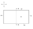
- FIG. 2 is a bottom view of box 1 in a closed state
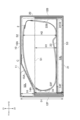
- FIG. 3 is a cross-sectional view taken along line III-III shown in FIG. 2.
- FIG. 3 shows box 1 in a state in which an item 2 is stored inside.
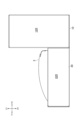
- FIG. 4 is a side view of box 1.
- FIG. 4 shows box 1 in an open state, with item 2 stored inside box 1.
- the box 1 when the box 1 is closed, the box 1 has a rectangular parallelepiped shape. As shown in FIG. 3 and FIG. 4, an item 2, such as an electronic product, is stored inside the box 1. As shown in FIG. 4, the box 1 has a storage section 20 in which the item 2 is stored, and a lid section 10 connected to the storage section 20. As shown in FIG. 1A and FIG. 3, when the box 1 is closed, the lid section 10 covers the upper side of the storage section 20. The lid section 10 can move between a closed position (see FIG. 1A) in which the storage section 20 is closed by covering the upper side of the storage section 20, and an open position (see FIG. 1C) in which the storage section 20 is opened. As shown in FIG. 1B and FIG.
- angles ⁇ 1 and ⁇ 2 indicate the angles between a straight line along the edge of the bottom end of the lid 10 (first left wall 12L described below) and a straight line along the edge of the top end of the storage section 20 (second left wall 22L described below).
- a storage space S1 is defined inside the storage section 20 in which at least a portion of the item 2 (the lower side of the item 2) is stored.
- a storage space S2 is defined inside the lid section 10 in which at least a portion of the item 2 (the upper side of the item 2) is stored.
- FIGS. 1B and 1C when the lid section 10 is open, the storage space S1 defined inside the storage section 20 is exposed upward.
- the height H1 in the vertical direction of the storage space S1 defined inside the storage section 20 is lower than the height H2 in the vertical direction of the item 2. Therefore, as shown in FIG.
- the upper side of the item 2 is exposed from the storage section 20. This makes it easier to touch the right and left sides of the upper side of the item 2 stored in the storage section 20 with your fingers, making it easier to remove the item 2 from the storage section 20.
- the storage section 20 in which the item 2 is stored has a plate-shaped bottom plate portion 21 that constitutes the lower end of the box 1.
- the lid portion 10 that covers the storage section 10 has a plate-shaped top plate portion 11 that constitutes the upper end of the box 1 when the box 1 is closed.
- the lid portion 10 has a first peripheral wall portion 12 that surrounds the top plate portion 11.
- the storage section 20 has a second peripheral wall portion 22 that surrounds the bottom plate portion 21. When the lid portion 10 is closed, the first peripheral wall portion 12 of the lid portion 10 covers the outer surface of the second peripheral wall portion 22 of the storage section 20.
- the bottom plate portion 21 is rectangular.
- the top plate portion 11 is also rectangular.
- the first peripheral wall portion 12 surrounding the top plate portion 11 has a first rear wall portion 12B, a first front wall portion 12F, a first left wall portion 12L, and a first right wall portion 12R.
- the first rear wall portion 12B and the first front wall portion 12F are separated in the front-to-rear direction (a first direction perpendicular to the up-down direction), and the first left wall portion 12L and the first right wall portion 12R extend from the first rear wall portion 12B to the first front wall portion 12F.
- the first left wall portion 12L and the first right wall portion 12R are separated in the left-to-right direction.
- the first rear wall portion 12B corresponds to the first side wall portion of the present disclosure
- the first front wall portion 12F corresponds to the second side wall portion of the present disclosure
- the first left wall portion 12L or the first right wall portion 12R corresponds to the third side wall portion of the present disclosure.
- the second peripheral wall portion 22 surrounding the bottom plate portion 21 has a second rear wall portion 22B, a second front wall portion 22F, a second left wall portion 22L, and a second right wall portion 22R.
- the second rear wall portion 22B and the second front wall portion 22F are separated in the front-rear direction, and the second left wall portion 22L and the second right wall portion 22R extend from the second rear wall portion 22B to the second front wall portion 22F.
- the second left wall portion 22L and the second right wall portion 22R are separated in the left-right direction.
- the vertical height D2 of the second peripheral wall portion 22 formed in the storage section 20 is lower than the height D1 of the first peripheral wall portion 12 formed in the lid portion 10.
- the vertical height D1 of the first peripheral wall portion 12 is higher than the height D2 of the second peripheral wall portion 22.
- a storage space S2 for storing the upper side of the item 2 is defined inside the lid portion 10.
- the item 2 stored in the storage section 20 can be exposed from the storage section 20, and the lid portion 10 can be prevented from interfering with the item 2 when the lid portion 10 is closed.
- the lid 10 has a supported surface 14A.
- the supported surface 14A is located below the top plate 11 and is supported by the upper end of the second peripheral wall 22 formed in the storage section 20. In this way, when the lid 10 is closed, the lid 10 can be prevented from sinking downward, and the outer shape of the box 1 can be prevented from collapsing.
- the supported surface 14A is in contact with the first front wall 12F (second side wall) and is formed on the inside of the first front wall 12F. As a result, the supported surface 14A is supported by the second front wall 22F formed in front of the second peripheral wall 22. As shown in FIG.
- the sum of the distance D3 between the top plate 11 and the supported surface 14A in the vertical direction and the height D2 of the second front wall 22F is equal to the height D1 of the first front wall 12F. This allows the bottom end of the lid 10 (more specifically, the first front wall 12F) to be aligned with the bottom end of the storage section 20 (more specifically, the second front wall 22F) when the lid 10 is closed.
- the lid 10 has an inclined surface 15A that extends diagonally upward and backward (towards the first rear wall 12B) from the supported surface 14A.
- the lid 10 also has a flat surface 16A that extends backward from the inclined surface 15A.
- the item 2 has a curved surface C over the entire upper end, and when the lid 10 is closed, the inclined surface 15A and the flat surface 16A face the curved surface C of the item 2. In this way, when the box 1 is tilted, the item 2 can be held down at at least two points, the inclined surface 15A and the flat surface 16A.
- the storage section 20 has a middle plate section 23 that constitutes the bottom of the storage space S1. As shown in Fig. 3, the middle plate section 23 is disposed along the bottom plate section 21, forming a space S3 between the middle plate section 23 and the bottom plate section 21. Items such as instruction manuals and warranties can also be stored in this space S3.
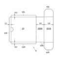
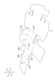
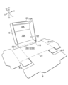
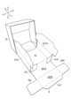
- FIG. 5A and 5B are plan views of a flat box material constituting the box 1.
- FIG. 5A is a development view of an outer member 8, which is a component of the box 1
- FIG. 5B is a development view of an inner member 9, which is another component of the box 1.
- the box material shown in FIG. 5A and FIG. 5B may be formed of, for example, cardboard or corrugated cardboard, or may be formed of plastic.
- the outer member 8 is formed by folding the box material shown in FIG. 5A along the creases.
- the inner member 9 is formed by folding the box material shown in FIG. 5B along the creases.
- the box 1 is formed by attaching the inner member 9 to the outer member 8.
- dotted lines indicate mountain folds
- dashed lines indicate valley folds.
- the middle plate 23 and the second rear wall 22B of the storage section 20 are formed by the inner member 9.
- the lid 10, the bottom plate 21 of the storage section 20, the second front wall 22F, the second left wall 22L, and the second right wall 22R, and other elements are formed by the outer member 8.
- the part constituting the outside of the wall and the part constituting the inside are connected via a single fold.
- the part constituting the outside of the wall and the part constituting the inside are connected via a single fold.
- the first front wall 12F has an outer wall 121F and an inner wall 122F that are connected to each other via a crease
- the first left wall 12L has an outer wall 121L and an inner wall 122L that are connected to each other via a crease
- the first right wall 12R has an outer wall 121R and an inner wall 122R that are connected to each other via a crease.
- the outer walls 121F, 121L, 121R, and 121B are connected to the top panel 11 via creases.
- the second front wall portion 22F has an outer wall portion 221F and an inner wall portion 222F that are connected to each other via a crease
- the second left wall portion 22L has an outer wall portion 221L and an inner wall portion 222L that are connected to each other via a crease
- the second right wall portion 22R has an outer wall portion 221R and an inner wall portion 222R that are connected to each other via a crease.
- the outer walls 221F, 221L, and 121R are connected to the bottom plate portion 21 via the crease.
- a slit K is formed in the bottom plate portion 21.
- the second rear wall portion 22B By folding a portion of the bottom plate portion 21 that is defined along this slit K along the crease, a hole that is connected to the space S3 (see FIG. 4) can be formed. Items such as instruction manuals and warranties can be stored in the space S3 through this hole.
- the second rear wall portion 22B also has an outer wall portion 221B and an inner wall portion 222B that are connected to each other via a fold.
- the first rear wall 12B constituting the first peripheral wall 12 of the lid 10 has an outer wall 121B and an inner wall 122B.
- the outer wall 121B and the inner wall 122B of the first rear wall 12B are spaced apart in the front-to-rear direction.
- the supported portion 14 on which the supported surface 14A is formed, the inclined portion 15 on which the inclined surface 15A is formed, and the flat portion 16 on which the flat surface 16A is formed are arranged between the outer wall 121B and the inner wall 122B.
- the supported surface 14A, the inclined surface 15A, and the flat surface 16A are defined on the back surface of the flat box material shown in FIG. 5A.
- the first left wall portion 12L is formed by folding the inner wall portion 122L against the outer wall portion 121L. As a result, a gap is formed between the outer wall portion 121L and the inner wall portion 122L of the first left wall portion 12L. Similarly, a gap is formed between the outer wall portion 121R and the inner wall portion 122R of the first right wall portion 12R. As shown in FIG. 5A, the first rear wall portion 12B and the first front wall portion 12F each have an insertion portion 31L, 32L that is inserted into the gap formed in the first left wall portion 12L.
- first front wall portion 12F and the first rear wall portion 12B each have an insertion portion 31R, 32R that is inserted into the gap formed in the first right wall portion 12L.
- the insertion portions 31L and 31R are connected to the left and right ends of the outer wall portion 121B constituting the first rear wall portion 12B via creases.
- the insertion portions 32L and 32R are connected to the left and right ends of the outer wall portion 121F constituting the first front wall portion 12F via creases.
- the insertion portions 31L and 32L formed on the first rear wall portion 12B and the first front wall portion 12F are inserted into the gap formed in the first left wall portion 12L
- the insertion portions 31R and 32R formed on the first rear wall portion 12B and the first front wall portion 12F are inserted into the gap formed in the first right wall portion 12R, so that the relative positions of the first rear wall portion 12B, the first front wall portion 12F, the first left wall portion 12L, and the first right wall portion 12R can be maintained in the first peripheral wall portion 12.
- the second left wall portion 22L is also formed by folding the inner wall portion 222L against the outer wall portion 221L.
- a gap is formed between the outer wall portion 221L and the inner wall portion 222L of the second left wall portion 22L.
- a gap is formed between the outer wall portion 221R and the inner wall portion 222R of the second right wall portion 22R, and between the outer wall portion 221F and the inner wall portion 222F of the second front wall portion 22F.
- the second left wall portion 22L and the second right wall portion 22R each have an insertion portion 41L, 41R that is inserted into the gap formed in the second front wall portion 22F.
- the insertion portion 41L is connected to the front end portion of the outer wall portion 221L that constitutes the second left wall portion 22L via a fold.
- the insertion portion 41R is connected to the front end of the outer wall portion 221R constituting the second right wall portion 22R via a crease.
- the second front wall portion 22F has insertion portions 42L, 42R that are inserted into a gap formed in the second left wall portion 22L and a gap formed in the second right wall portion 22R, respectively.
- the insertion portion 42L is connected to the left end of the inner wall portion 222F constituting the second front wall portion 22F via a crease, and the insertion portion 42R is connected to the right end of the inner wall portion 222F via a crease.
- the insertion portions 41L, 41R formed on the second left wall portion 22L and the second right wall portion 22R, respectively, are inserted into the gaps formed in the second front wall portion 22F
- the insertion portions 42L, 42R formed on the second front wall portion 22F are inserted into the gaps formed in the second left wall portion 22L and the gaps formed in the second right wall portion 22R, respectively, thereby maintaining the relative positions of the second front wall portion 22F, the second left wall portion 22L, and the second right wall portion 22R in the second peripheral wall portion 22.
- the second rear wall 22B of the storage section 20 provided in the inner member 9 has an insert portion 43L connected to the left end of the outer wall 221B via a crease, and an insert portion 43R connected to the right end of the outer wall 221B via a crease.
- the insert portion 43L is inserted into the gap formed between the outer wall 221L and the inner wall 222L of the second left wall 22L.
- the insert portion 43R is inserted into the gap formed between the outer wall 221R and the inner wall 222R of the second right wall 22R. This allows the inner member 9 to be attached to the outer member 8 as shown in FIG. 6G described later, and the relative positions of the second rear wall 22B, the second left wall 22L, and the second right wall 22R can be maintained.
- the first peripheral wall 12 of the lid 10 is connected to the storage section 20 via a crease.
- the first rear wall 12B (more specifically, the outer wall 121B) forming the first peripheral wall 12 is connected to the storage section 20 (more specifically, the bottom plate 21 constituting the storage section 20) via a crease.
- the outer wall portions 221F, 221L, and 221R are connected to the bottom plate portion 21 via creases.
- the outer wall portions 121F, 121L, 121R, and 121B are connected to the top plate portion 11 via creases.
- the inclined portion 15 is connected to the supported portion 14 via a crease
- the flat portion 16 is connected to the inclined portion 15 via a crease.
- the inner wall portion 122B of the first rear wall portion 12B formed in the lid portion 10 is connected to the flat portion 16 via a crease.
- the outer wall portion 121B of the first rear wall portion 12B is located at the front end portion of the lid portion 10
- the inner wall portion 122B of the first rear wall portion 12B is located at the rear end portion of the lid portion 10.
- the inner wall portions 222F, 222L, 222R formed in the storage section 20 and the inner wall portion 122B formed in the lid portion 10 have anti-slip pieces 51F, 51L, 51R, 51B that are connected to these portions via folds.
- the anti-slip pieces 51F, 51L, 51R, 51B come into contact with the upper surface of the bottom plate portion 21, thereby preventing the inner wall portions 222F, 222L, 222R, 122B that are connected to these ends from moving (slipping) inwardly into the storage section 20.
- anti-slip pieces 52L, 52R that are connected to the inclined portion 15 via valley folds are formed at the left and right ends of the inclined portion 15. As shown in FIG. 3, the edges of the anti-slip pieces 52L, 52R come into contact with the top plate 11 and the first front wall 12F, preventing the inclined portion 15 from moving (slipping) inside the lid 10.
- the inner wall portion 222L forming the second left wall portion 22L and the inner wall portion 222R forming the second right wall portion 22R each have a pressing piece 54L, 54R at their front end.
- the pressing pieces 54L, 54R press inward the insertion portions 43L, 43R (see FIG. 5B, FIG. 6F, FIG. 6G) of the inner member 9 housed in the gap of the second left wall portion 22L and the gap of the second right wall portion 22R, respectively.
- the rear end portions of the inner walls 222L, 222R are provided with adjustment pieces 55L, 55R for making the thickness of the second left wall portion 22L and the second right wall portion 22R uniform.
- the middle plate portion 23 has support pieces 53F, 53L, and 53R that are connected to the front end, left end, and right end of the middle plate portion 23 via folds.
- the support pieces 53F, 53L, and 53R are folded relative to the middle plate portion 23, so that the support pieces 53F, 53L, and 53R support the middle plate portion 23 and secure a space S3 between the bottom plate portion 21.
- the widths (heights) E1, E2, and E3 of the support pieces 53F, 53L, and 53R are all equal. Also, as shown in FIG.
- the width E4 of the outer wall portion 221B is greater than the width E5 of the inner wall portion 222B.
- the difference between the width E4 and the width E5 in the second rear wall portion 22B is equal to the widths E1, E2, and E3 of the support pieces 53F, 53L, and 53R. This allows the middle plate 23 to be positioned horizontally inside the storage section 20.
- the insertion parts 31L, 31R formed in the first rear wall part 12B of the lid part 10 function as movable parts that can move relative to the first left wall part 12L or the first right wall part 12R.
- the insertion parts 31L, 31R which are movable parts, are allowed to move between a first position (see Figures 1A and 1B) in which the entirety is disposed in the gap of the first left wall part 12L or the gap of the first right wall part 12R, and a second position (see Figure 1C) in which a part of the insertion parts is exposed from the gap of the first left wall part 12L or the gap of the first right wall part 12R.
- the lid part 10 when the lid part 10 is in the closed position, the insertion parts 31L, 31R are in the first position in which the entirety is disposed inside the gap. Also, as shown in Figure 1C, when the insertion parts 31L, 31R are in the second position in which a part of the insertion parts 31L, 31R is exposed from the gap, the lid part 10 is in the open position. In this way, by allowing the insertion portions 31L, 31R to move relative to the gap formed in the first left wall portion 12L and the gap formed in the first right wall portion 12R in the lid portion 10, the position of the first left wall portion 12L and the first right wall portion 12R can be maintained while allowing the lid portion 10 to be opened and closed. Also, as shown in Figures 1C and 5A, by forming the edges of the insertion portions 31L, 31R into an arc shape, it becomes possible to move the lid portion 10 to an angle ⁇ 2 (see Figure 1C) that is greater than 90 degrees.
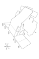
- Assembling the Box 6A to 6G are diagrams for explaining a method of assembling the box 1. Note that in Fig. 6A to 6G, the illustration of the slit K provided in the bottom plate portion 21 is omitted.
- the insertion portions 31L, 31R are bent upward relative to the outer wall portion 121B.
- the insertion portions 32L, 32R are bent upward relative to the outer wall portion 121F.
- the anti-slip pieces 52L, 52R are also bent upward relative to the inclined portion 15.
- the top plate portion 11 of the lid portion 10 is bent upward relative to the outer wall portion 121B, and the outer wall portion 121F is bent forward relative to the top plate portion 11.
- the outer wall 121L is folded forward relative to the top plate 11, and the inner wall 122L is folded backward relative to the outer wall 121L to form the first left wall 12L of the lid 10.
- the left insertion portions 31L, 32L are accommodated in the gap between the outer wall 121L and the inner wall 122L (the gap formed in the first left wall 12L).
- the outer wall 121R and the inner wall 122R are folded along the creases to form the first right wall 12R of the lid 10.
- the right insertion portions 31R, 32R are accommodated in the gap between the outer wall 121R and the inner wall 122R (the gap formed in the first right wall 12R).
- the inner wall portion 122F is folded backward relative to the outer wall portion 121F, and the supported portion 14, the inclined portion 15, the flat portion 16, and the inner wall portion 122B are folded along the creases, so that these portions and the anti-slip pieces 52L, 52R folded relative to the inclined portion 15 are accommodated inside the lid portion 10.
- the anti-slip piece 51B which is connected to the inner wall portion 122B via the creases, is positioned outside the storage space S2 and comes into contact with the bottom plate portion 21.
- the outer wall portions 221L and 221R are bent upward relative to the bottom plate portion 21.
- the insertion portions 41L and 41R are bent backward relative to the outer wall portions 221L and 221R.
- the outer wall portion 221F is bent upward relative to the bottom plate portion 21, and the inner wall portion 222F is bent downward relative to the outer wall portion 221F to form the second front wall portion 22F of the storage portion 20.
- the insertion portions 41L and 41R located at the front side of the storage portion 20 are accommodated in the gap between the outer wall portion 221F and the inner wall portion 222F (the gap formed in the second front wall portion 22F).
- the anti-slip piece 51F is bent inward relative to the inner wall portion 222F and comes into contact with the bottom plate portion 21.
- the pressing piece 54L and the adjustment piece 55L are folded against the inner wall 222L, and the inner wall 222L is folded downward against the outer wall 221L to form the second left wall 22L of the storage section 20.
- the pressing piece 54L and the adjustment piece 55L are accommodated in the gap between the outer wall 221L and the inner wall 222L (the gap formed in the second left wall 22L).
- the pressing piece 54R, the adjustment piece 55R, and the inner wall 222R are folded along the creases to form the second right wall 22R of the storage section 20.
- the anti-slip pieces 51L, 51R are folded inward against the inner walls 222L, R to come into contact with the bottom plate 21.
- the flat box material of the inner member 9 (see FIG. 5B) is folded along the creases to form the inner member 9 shown in FIG. 6G.
- the inner member 9 is attached to the outer member 8 by inserting the insertion portions 43L, 43R of the inner member 9 into the gaps formed in the second left wall portion 22L and the gaps formed in the second right wall portion 22R, respectively. This forms the middle plate portion 23 and the second rear wall portion 22B in the storage section 20.
- the box 1 can be assembled from box materials such as plate-shaped cardboard or corrugated cardboard.
- the outer and inner surfaces of the box 1 formed as described above are formed only by the back surface of the flat box material shown in FIG. 5A or the surface of the flat box material shown in FIG. 5B, except for the movable insertion parts 31L and 31R.
- the upper surface of the top plate part 11, the outer and inner surfaces of the first peripheral wall part 12, the supported surface 14A, the inclined surface 15A, and the flat surface 16A, which are the back side of the lid part 10 are part of the back surface (first surface) of the box material shown in FIG. 5A.
- the lower surface of the bottom plate part 21, and the outer and inner surfaces of parts of the second peripheral wall part 22 are also part of the back surface of the box material shown in FIG. 5A.
- the upper surface of the middle plate part 23 and the inner and outer surfaces of the second rear wall part 22B of the second peripheral wall part 22 are part of the surface of the flat box material shown in FIG. 5B. Therefore, for example, when coloring or coating the inner and outer surfaces of box 1, it is only necessary to perform the coloring or coating process on one side of the flat box material, thereby reducing the manufacturing cost of box 1.
- the box 1 described in this embodiment is formed by combining an outer member 8 formed by folding a plate-shaped box material, as shown in FIG. 6G, with an inner member 9 formed by folding a plate-shaped box material.
- the box 1 includes a storage section 20 for storing an item 2, and a lid section 10 covering the upper side of the storage section 20.
- the lid section 10 has a top plate section 11 and a first peripheral wall section 12 surrounding the top plate section 11, and the storage section 20 has a bottom plate section 21 and a second peripheral wall section 22 surrounding the bottom plate section 21.
- the first peripheral wall section 12 has a first rear wall section 12B connected to the bottom plate section 21 via a fold.
- the second peripheral wall section 22 of the storage section 20 is lower in height than the first peripheral wall section 12 of the lid section 10, and storage spaces S1 and S2 are formed on the inside of the storage section 20 and the inside of the lid section 10, respectively.
- the lid portion 10 is positioned below the top plate portion 11 when the lid portion 10 is closed, and has a supported surface 14A that is supported by the upper end portion of the second peripheral wall portion 22 formed on the storage portion 20.
- the second peripheral wall portion 22 of the storage portion 20 supports the supported surface 14A of the lid portion 10, thereby preventing the lid portion 10 from sinking downward relative to the storage portion 20 and preventing the external shape of the box 1 from collapsing.
- the present invention is not limited to the above embodiment.
- the shape of the box 1 described in the embodiment is a rectangle in a plan view, but the shape of the box 1 in a plan view may be a polygon such as a triangle or a pentagon, or may have an arc-shaped portion.
- the height of the second peripheral wall portion 22 of the storage section 20 can be made lower than the height of the first peripheral wall portion 12 of the lid portion 10 to make it easier to remove the item 2 from inside the storage section 20.
- the lid portion 10 by providing the lid portion 10 with a supported surface 14A that is supported by the second peripheral wall portion 22 of the storage section 20 when the lid portion 10 is closed, the lid portion 10 can be prevented from sinking downward relative to the storage section 20.
- the box 1 which is an example of an embodiment of the present disclosure, includes a storage section 20 and a lid section 10 that covers the upper side of the storage section 20.
- the lid section 10 has a top plate section 11 and a first peripheral wall section 12 that surrounds the top plate section 11.
- the storage section 20 has a bottom plate section 21 and a second peripheral wall section 22 that surrounds the bottom plate section.
- the first peripheral wall section 12 is connected to the storage section 20 via a fold.
- the second peripheral wall section 22 is lower in height than the first peripheral wall section 12.
- the lid section 10 further has a supported surface 14A that is disposed below the top plate section 11 and supported by the upper end of the second peripheral wall section 22 when the lid section 10 is closed. This makes it easier to take out the item 2 stored inside the box 1.
- the first peripheral wall portion 12 may include a first rear wall portion 12B (first side wall portion) and a first front wall portion 12F (second side wall portion) that are separated from each other in the front-rear direction (a first direction perpendicular to the up-down direction).
- the first rear wall portion 12B may be connected to the storage section 20 via a fold.
- the supported surface 14A may be formed on the inside of the first front wall portion 12F.
- the first front wall 12F may have an outer wall 121F that constitutes the outside of the lid 10, and an inner wall 122F that is connected to the outer wall 121F via a fold and constitutes the inside of the lid 10.
- the supported surface 14A may be connected to the inner wall 122F via a fold.
- the lid portion 10 may further have an inclined surface 15A extending obliquely upward from the supported surface 14A toward the first rear wall portion 12B.
- At least a portion of the storage section 20 and at least a portion of the lid section 10 may be formed by bending a flat member having a first surface.
- the upper surface of the top plate section 11, the supported surface 14A, and the inclined surface 15A may be part of the first surface.
- the first peripheral wall 12 may have a first left wall 12L (third side wall) extending from the first side wall 12 to the first front wall 12F.
- the first left wall 12L may have an outer wall 121L constituting the outside of the lid 10, an inner wall 122L connected to the outer wall 121L via a fold and constituting the inside of the lid 10, and a gap between the inner wall and the outer wall.
- the lid 10 may have an insertion portion 31L (movable portion) inserted into the gap.
- the insertion portion 31L may be allowed to move between a first position where the entirety of the insertion portion 31L is disposed in the gap and a second position where a part of the insertion portion 31L is exposed from the gap.
- the lid 10 When the lid 10 is in the closed position, the insertion portion 31L may be in the first position.
- the cover portion 10 may be in an open position.
Landscapes
- Engineering & Computer Science (AREA)
- Mechanical Engineering (AREA)
- Cartons (AREA)
Priority Applications (3)
| Application Number | Priority Date | Filing Date | Title |
|---|---|---|---|
| CN202380063280.8A CN119731094A (zh) | 2022-10-25 | 2023-10-16 | 盒和盒材料 |
| JP2024552976A JPWO2024090270A1 (https=) | 2022-10-25 | 2023-10-16 | |
| EP23882476.7A EP4610184A1 (en) | 2022-10-25 | 2023-10-16 | Box, and box material |
Applications Claiming Priority (2)
| Application Number | Priority Date | Filing Date | Title |
|---|---|---|---|
| JP2022170861 | 2022-10-25 | ||
| JP2022-170861 | 2022-10-25 |
Publications (1)
| Publication Number | Publication Date |
|---|---|
| WO2024090270A1 true WO2024090270A1 (ja) | 2024-05-02 |
Family
ID=90830743
Family Applications (1)
| Application Number | Title | Priority Date | Filing Date |
|---|---|---|---|
| PCT/JP2023/037412 Ceased WO2024090270A1 (ja) | 2022-10-25 | 2023-10-16 | 箱及び箱材料 |
Country Status (4)
| Country | Link |
|---|---|
| EP (1) | EP4610184A1 (https=) |
| JP (1) | JPWO2024090270A1 (https=) |
| CN (1) | CN119731094A (https=) |
| WO (1) | WO2024090270A1 (https=) |
Citations (3)
| Publication number | Priority date | Publication date | Assignee | Title |
|---|---|---|---|---|
| JPS4513328Y1 (https=) * | 1966-07-20 | 1970-06-08 | ||
| JP2005035547A (ja) * | 2003-07-15 | 2005-02-10 | Konica Minolta Medical & Graphic Inc | ロール状感光材料用包装箱、ロール状感光材料用包装箱の製造方法 |
| WO2014061362A1 (ja) | 2012-10-15 | 2014-04-24 | 株式会社ソニー・コンピュータエンタテインメント | 操作デバイス |
-
2023
- 2023-10-16 JP JP2024552976A patent/JPWO2024090270A1/ja active Pending
- 2023-10-16 WO PCT/JP2023/037412 patent/WO2024090270A1/ja not_active Ceased
- 2023-10-16 CN CN202380063280.8A patent/CN119731094A/zh active Pending
- 2023-10-16 EP EP23882476.7A patent/EP4610184A1/en active Pending
Patent Citations (3)
| Publication number | Priority date | Publication date | Assignee | Title |
|---|---|---|---|---|
| JPS4513328Y1 (https=) * | 1966-07-20 | 1970-06-08 | ||
| JP2005035547A (ja) * | 2003-07-15 | 2005-02-10 | Konica Minolta Medical & Graphic Inc | ロール状感光材料用包装箱、ロール状感光材料用包装箱の製造方法 |
| WO2014061362A1 (ja) | 2012-10-15 | 2014-04-24 | 株式会社ソニー・コンピュータエンタテインメント | 操作デバイス |
Also Published As
| Publication number | Publication date |
|---|---|
| JPWO2024090270A1 (https=) | 2024-05-02 |
| CN119731094A (zh) | 2025-03-28 |
| EP4610184A1 (en) | 2025-09-03 |
Similar Documents
| Publication | Publication Date | Title |
|---|---|---|
| JP6684036B2 (ja) | 包装箱およびブランクシート | |
| WO2024090270A1 (ja) | 箱及び箱材料 | |
| JPWO2024090270A5 (https=) | ||
| JP6413928B2 (ja) | トレイ | |
| JP4620499B2 (ja) | 紙箱 | |
| JP7543957B2 (ja) | トレイ | |
| JP6637453B2 (ja) | 包装箱 | |
| JP5378958B2 (ja) | 組み立て包装箱 | |
| JPWO2024090271A5 (https=) | ||
| EP4610191A1 (en) | Box and box material | |
| JP6803363B2 (ja) | 収容箱 | |
| JP5204812B2 (ja) | 本収納ケース | |
| JP2018024459A (ja) | 円筒体の梱包容器及び円筒体の輸送方法 | |
| US20260125178A1 (en) | Box and box material | |
| JP6849527B2 (ja) | 包装箱 | |
| JP6287171B2 (ja) | 梱包材及びシート | |
| JP6733197B2 (ja) | 組立箱 | |
| JP7298422B2 (ja) | 包装箱 | |
| JP7431633B2 (ja) | 包装箱 | |
| JP3169007U (ja) | 包装用箱 | |
| JP7102291B2 (ja) | 包装容器 | |
| JP3175267U (ja) | 包装用箱 | |
| JP2025033331A (ja) | 包装構造 | |
| JP5955976B2 (ja) | ヒンジリッドパッケージ | |
| JP2025040567A (ja) | 包装箱 |
Legal Events
| Date | Code | Title | Description |
|---|---|---|---|
| 121 | Ep: the epo has been informed by wipo that ep was designated in this application |
Ref document number: 23882476 Country of ref document: EP Kind code of ref document: A1 |
|
| WWE | Wipo information: entry into national phase |
Ref document number: 202380063280.8 Country of ref document: CN |
|
| WWP | Wipo information: published in national office |
Ref document number: 202380063280.8 Country of ref document: CN |
|
| WWE | Wipo information: entry into national phase |
Ref document number: 2024552976 Country of ref document: JP |
|
| WWE | Wipo information: entry into national phase |
Ref document number: 2023882476 Country of ref document: EP |
|
| NENP | Non-entry into the national phase |
Ref country code: DE |
|
| ENP | Entry into the national phase |
Ref document number: 2023882476 Country of ref document: EP Effective date: 20250526 |
|
| WWP | Wipo information: published in national office |
Ref document number: 2023882476 Country of ref document: EP |