WO2024089985A1 - 通信システム及び車両 - Google Patents
通信システム及び車両 Download PDFInfo
- Publication number
- WO2024089985A1 WO2024089985A1 PCT/JP2023/029847 JP2023029847W WO2024089985A1 WO 2024089985 A1 WO2024089985 A1 WO 2024089985A1 JP 2023029847 W JP2023029847 W JP 2023029847W WO 2024089985 A1 WO2024089985 A1 WO 2024089985A1
- Authority
- WO
- WIPO (PCT)
- Prior art keywords
- terminal
- vehicle
- information
- driver
- unit
- Prior art date
- Legal status (The legal status is an assumption and is not a legal conclusion. Google has not performed a legal analysis and makes no representation as to the accuracy of the status listed.)
- Ceased
Links
Images




Classifications
-
- G—PHYSICS
- G06—COMPUTING OR CALCULATING; COUNTING
- G06F—ELECTRIC DIGITAL DATA PROCESSING
- G06F21/00—Security arrangements for protecting computers, components thereof, programs or data against unauthorised activity
- G06F21/30—Authentication, i.e. establishing the identity or authorisation of security principals
- G06F21/31—User authentication
- G06F21/32—User authentication using biometric data, e.g. fingerprints, iris scans or voiceprints
-
- G—PHYSICS
- G06—COMPUTING OR CALCULATING; COUNTING
- G06F—ELECTRIC DIGITAL DATA PROCESSING
- G06F21/00—Security arrangements for protecting computers, components thereof, programs or data against unauthorised activity
- G06F21/30—Authentication, i.e. establishing the identity or authorisation of security principals
- G06F21/31—User authentication
- G06F21/34—User authentication involving the use of external additional devices, e.g. dongles or smart cards
- G06F21/35—User authentication involving the use of external additional devices, e.g. dongles or smart cards communicating wirelessly
-
- G—PHYSICS
- G06—COMPUTING OR CALCULATING; COUNTING
- G06F—ELECTRIC DIGITAL DATA PROCESSING
- G06F21/00—Security arrangements for protecting computers, components thereof, programs or data against unauthorised activity
- G06F21/70—Protecting specific internal or peripheral components, in which the protection of a component leads to protection of the entire computer
- G06F21/82—Protecting input, output or interconnection devices
Definitions
- the present invention relates to a communication system and a vehicle.
- Patent Document 1 discloses a technology that, when making a payment using a mobile terminal, acquires a password generated by an IC chip for authentication data embedded in an item the user is carrying and executes the payment.
- a motorcycle driver may need to operate a navigation application (hereinafter simply referred to as an "app") on a mobile terminal such as a smartphone (hereinafter simply referred to as a "terminal") while stopped at a traffic light, etc.
- a motorcycle driver may need to operate a payment application on the terminal when refueling, etc.
- biometric authentication or password entry is required to unlock the terminal.
- driver P when driver P is wearing driver equipment such as a helmet or gloves, it may be difficult to perform biometric authentication using the driver's fingerprint information, face image, etc., or to enter a password. From the perspective of improving convenience, it is preferable for the driver to be able to unlock the terminal while wearing the equipment.
- the present invention provides technology that allows a driver to unlock a terminal while wearing an accessory.
- a communication system includes a vehicle, an equipment of the driver that provides authentication information for authenticating the driver to the vehicle, and a terminal of the driver that has a communication unit capable of communicating with the vehicle, the vehicle comprising: an acquisition unit that acquires the authentication information from the equipment; A control unit having at least a processing unit that processes the authentication information; A communication unit capable of communicating with the terminal, The control unit transmits release information for determining whether to release a lock state of the driver's terminal to the terminal via the communication unit in response to the acquisition of the authentication information by the acquisition unit, When the received unlocking information satisfies an unlocking condition, the terminal unlocks the locked state of the terminal, making the terminal available for use.
- the communication system of the present invention allows the driver to unlock the terminal while wearing the accessory.
- the vehicle's communication unit By using the vehicle's communication unit, it becomes unnecessary to provide equipment with dedicated communication devices for communication with terminals. This makes it possible to reduce the number of dedicated communication devices, reducing costs and improving convenience.
- FIG. 1 is a block diagram showing a functional configuration of a communication system according to an embodiment.
- FIG. 1 is a diagram illustrating a configuration of a communication system according to an embodiment.
- FIG. 2 is a right side view of the vehicle according to the embodiment.
- FIG. 2 is a view of the vehicle width direction as seen from the driver P side.
- FIG. 2 is a diagram for explaining a process flow 1 of the vehicle communication system according to the embodiment;
- FIG. 4 is a diagram for explaining a second process flow of the vehicle communication system according to the embodiment;
- FIG. 4 is a diagram for explaining a process flow 3 of the vehicle communication system according to the embodiment.
- FIG. 4 is a diagram for explaining a processing flow 4 of the vehicle communication system according to the embodiment.
- Fig. 1 is a block diagram showing a functional configuration of a communication system STM according to an embodiment.
- Fig. 2 is a diagram showing a schematic configuration of the communication system STM.
- the communication system STM includes a vehicle 1, a mobile terminal such as a smartphone carried by a driver P of the vehicle 1 (hereinafter, a terminal 230), and a transmission device 250 mounted on an accessory 240 worn by the driver P when driving the vehicle 1.
- the terminal 230 is held on the vehicle 1 by a holding member (not shown) with an operation display unit 234 facing the rear of the vehicle 1.
- the accessory 240 includes, for example, a glove 241, a smart watch 242, and a helmet 243.
- the accessory 240 may be the helmet 243 or a headset 244 that is worn on the head of the driver P and that can input voice information using a microphone or the like.
- the transmission device 250 mounted on the equipment 240 of the driver P has, as its functional configuration, a biometric information acquisition unit 251, a storage unit 252, and a transmission unit 253.
- the transmission device 250 is, for example, a wireless communication tag capable of short-range wireless communication, or an IC (Integrated Circuit) chip device capable of short-range wireless communication such as Bluetooth (registered trademark).
- the embodiment of the present application does not need to have the biometric information acquisition unit 251.
- the transmission device 250 in the embodiment of the present application may be mounted on the equipment 240 with the biometric information acquisition unit 251, the storage unit 252, and the transmission unit 253 each mounted as separate devices, or any two of them mounted as the same device.
- the biometric information acquisition unit 251 stores biometric information of the driver P acquired from an external input device capable of short-range wireless communication in the storage unit 252.
- the biometric information of the driver P includes, for example, fingerprint information, a facial image, etc. of the driver P.
- the fingerprint information and the facial image are input by an external input device, and the biometric information acquisition unit 251 stores the input biometric information of the driver P in the storage unit 252.
- the transmission unit 253 reads the biometric information of the driver P stored in the storage unit 252 and transmits it to the vehicle 1.
- the storage unit 252 may store in advance identification information unique to the equipment 240, and the transmission unit 253 may transmit the unique identification information stored in the storage unit 252 to the vehicle 1.
- the vehicle 1 is provided with an acquisition unit 221 that acquires authentication information for authenticating the driver P from the equipment 240 (transmission device 250) of the driver P, and the acquisition unit 221 acquires, via the transmission unit 253, at least one of the biometric information of the driver P of the vehicle 1 or the identification information stored in a tag (e.g., an IC tag) individually built into the equipment 240, as authentication information.
- a tag e.g., an IC tag
- the acquisition unit 221 of the vehicle 1 acquires authentication information from the transmission device 250 by short-range wireless communication.
- the acquisition unit 221 acquires at least one of biometric information or identification information as authentication information from the transmission device 250.
- the acquisition unit 221 can be installed at any location of the vehicle 1.
- the acquisition unit 221 may be provided in the throttle operator 8a (right handle lever), the handle switch 202, and the operator 200 including the ignition SW.
- the acquisition unit 221 may also be provided in the left handle lever 8b or the center of the handlebar 11.
- the number of acquisition units 221 is not limited to one, and multiple acquisition units 221 may be provided in the vehicle 1.
- the acquisition unit 221 may also support short-range wireless communication such as Bluetooth (registered trademark).
- a communication link for example, by short-range wireless communication, is established between the acquisition unit 221 and the transmission unit 253 of the vehicle 1.
- the acquisition unit 221 and the transmission unit 253 can exchange data via this communication link.
- the accessory 240 is a helmet 243 or a headset 244
- the driver P operates the handlebar switch 202 of the vehicle 1 to establish a communication link between the acquisition unit 221 and the transmission device 250 (transmission unit 253) of the helmet 243 or headset 244, and the acquisition unit 221 acquires at least one of the biometric information or the identification information from the transmission device 250 as authentication information via this communication link.
- the terminal 230 carried by the driver P of the vehicle 1 has, as internal components, a control unit 231 (an authentication unit 232, a communication unit 233), an operation display unit 234, and a storage unit 235.
- the operation display unit 234 functions as a touch panel type user interface capable of displaying a screen.
- the control unit 231 is responsible for the overall processing of the terminal 230, and processes information acquired via the communication unit 233 or the operation display unit 234.
- the control unit 231 locks the terminal 230 so that it cannot be used.
- the control unit 231 unlocks the terminal 230 and makes the terminal 230 usable.
- the authentication unit 232 performs user authentication based on the release information received from the vehicle 1 or the information input from the operation display unit 234.
- the communication unit 233 may support short-range wireless communication such as Bluetooth (registered trademark).
- a communication link is established between the vehicle 1 and the terminal 230, for example, by short-range wireless communication.
- the vehicle 1 and the terminal 230 can exchange data via this communication link.
- the storage unit 235 stores various programs executed by the control unit 231, and also functions as a work area when the control unit 231 executes processing.
- the storage unit 235 also stores information acquired via the communication unit 233.
- the storage unit 235 can store, for example, information related to user authentication (cancellation conditions) in advance via the communication unit 233.
- the control unit 231 unlocks the terminal 230 and makes the terminal 230 available.
- the control unit 231 unlocks the terminal 230 and makes the terminal 230 available.
- the unlocking of the terminal 230 based on the unlocking information will be described later with reference to the process flows in Figures 5 to 8.
- the operator 200 includes, as exemplary components, a throttle operator 8a, a handle switch 202 (handle SW), and an ignition switch 203 (ignition SW).
- the measurement device 210 has, as an exemplary configuration, a vehicle speed measurement unit 211 that measures the vehicle speed of the vehicle 1.
- the configuration of the measurement device 210 is not limited to this example, and various other measurement units are provided in the vehicle 1.
- the measurement device 210 includes a rotation speed measurement unit that measures the rotation speed of the drive source 21, a throttle opening measurement unit that measures the operation amount (throttle opening) of the throttle operator 8a, a gear information measurement unit that measures the gear setting of the transmission 22, and a positioning measurement unit that measures the position information of the vehicle 1.
- the ECU 220 has a control unit 222 and a memory unit 223 as its functional components.
- the ECU 220 has one or more central processing units (CPUs) as a processor that handles the overall control processing of the vehicle, and the processor reads out a program stored in the memory unit 223 and executes the program to implement the functions of the acquisition unit 221 and the control unit 222.
- CPUs central processing units
- the functional components of the ECU 220 may be implemented using integrated circuits or the like as long as they perform similar functions.
- the control unit 222 is responsible for the overall processing in the vehicle 1, and processes information acquired via equipment (including at least an acquisition unit and a communication unit) mounted on each vehicle. In response to acquiring the authentication information, the control unit 222 acquires the release conditions from the driver P's terminal 230 via the communication unit 224. In response to acquiring the authentication information, the control unit 222 acquires release information for determining whether or not to release the locked state of the driver P's terminal 230 via the acquisition unit, and when the release information satisfies the release conditions, outputs a signal instructing the terminal 230 to release the locked state via the communication unit 224.
- the control unit 231 of the terminal 230 releases the locked state of the terminal 230 based on the release instruction signal received from the vehicle 1 via the communication unit 233, making the terminal 230 available. In this case, the control unit 231 of the terminal 230 releases the locked state of the terminal 230 in response to receiving the release instruction signal, without determining whether the release information matches the release conditions. This makes it possible to reduce the processing load on the terminal 230.
- the memory unit 223 stores various programs executed by the control unit 222, and also functions as a work area when the control unit 222 executes processing.
- the memory unit 223 also stores information acquired via the communication unit 224.
- the ECU 220 acquires release information for determining whether or not to release the locked state of the driver P's terminal 230 from the memory unit 223, the acquisition unit 221, or the operator of the vehicle 1.
- the release information includes, for example, vehicle identification information for identifying the vehicle 1.
- the memory unit 223 stores identification information for identifying the vehicle 1. This identification information is, for example, at least a portion of the information registered in a vehicle inspection certificate, etc. If the vehicle 1 is owned by the driver P, the identification information for identifying the vehicle 1 can be used as release information for determining whether to release the locked state of the driver P's terminal 230.
- the acquisition unit 221 acquires the identification information for identifying the vehicle 1 from the memory unit 223 of the vehicle 1 as release information.
- the release information also includes, for example, at least one of the biometric information or identification information (authentication information) of the driver P acquired by the acquisition unit.
- the acquisition unit 221 acquires at least one of the biometric information or identification information as authentication information from the equipment 240 (transmission device 250) of the driver P via short-range wireless communication or an established communication link.
- the release information for determining whether or not to release the locked state of the terminal 230 also includes at least one of the biometric information (authentication information) or identification information.
- the release information also includes, for example, an operation pattern (first operation pattern) input from an operator of the vehicle 1.
- the operation pattern is set, for example, by a combination of operation patterns in which the driver P operates the handlebar switch 202, etc.
- it is set by a combination of operations of the cross keys 80A to 80D of the handlebar switch 202 on the left side of the vehicle 1.
- Various combinations of operation patterns are possible. For example, the cross key 80A (up) is pressed twice, and then the cross key 80B (down) is pressed twice. Then, the cross key 80C (left) is pressed once, and then the cross key 80D (right) is pressed once.
- the driver P can set any operation pattern.
- an operation pattern (second operation pattern) that makes the terminal 230 available for a predetermined time based on the state in which the vehicle 1 is powered off can be stored in the storage unit 223.
- the driver P can set any second operation pattern.
- the second operation pattern can also be included in the release information.
- the release information used by the acquisition unit 221 to determine whether or not to release the locked state of the driver P's terminal 230 includes the operation patterns (first operation pattern and second operation pattern) input from the operator of the vehicle 1.
- the operation pattern can be registered in advance in the memory unit 223 by the driver P operating the handlebar switches 202 (80A-80D) and other devices such as the front brake lever 16a, clutch lever 16b, and throttle operator 8a before the vehicle 1 starts traveling.
- the operation pattern registered in the memory unit 223 is transmitted to the terminal 230 via the communication unit 224 and stored in the memory unit 235.
- the operation pattern is stored in the memory unit 235 as a release condition.
- the timing for registering the operation pattern is not limited to before the vehicle starts to travel, and the operation pattern can be registered at any time as long as the vehicle 1 is powered on and stopped.
- vehicle 1 and terminal 230 are provided by a sharing service, it is possible to specify an operation pattern in advance on terminal 230 or the like before or at the time of reserving vehicle 1, and to register the specified operation pattern in advance.
- the operation pattern previously registered in storage unit 223 of vehicle 1 is transmitted to terminal 230 via communication unit 224 and stored in storage unit 235 of terminal 230.
- the operation pattern is stored in storage unit 235 as a release condition.
- driver P can operate controls such as handlebar switches 202 (80A-80D) to register an operation pattern in advance in storage unit 223.
- the operation pattern registered in storage unit 223 is transmitted to terminal 230 via communication unit 224 and stored in storage unit 235.
- the operation pattern is stored in storage unit 235 as a release condition.
- a two-stage unlocking determination may be performed based on unlocking conditions that combine authentication information acquired by the acquisition unit 221 from the equipment 240 of the driver P and an operation pattern.
- the locked state of the terminal 230 may be unlocked.
- the release information (vehicle identification information, authentication information, first operation pattern, and second operation pattern) is pre-stored as release conditions in the storage unit 235 of the terminal 230.
- the release determination is made on the terminal 230 side, it is determined whether the release information received from the vehicle 1 matches the release conditions stored in the storage unit 235 (FIGS. 5 and 7).
- the vehicle 1 requests the terminal 230 to transmit the release conditions. Then, the vehicle 1 determines whether the release information matches the release conditions received from the terminal 230 (FIGS. 6 and 8).
- the communication unit 224 may support short-range wireless communication such as Bluetooth (registered trademark).
- a communication link is established between the vehicle 1 and the terminal 230, for example, by short-range wireless communication.
- the vehicle 1 and the terminal 230 can exchange data via this communication link.
- the communication unit 224 transmits to the terminal 230 release information for determining whether or not to release the lock state of the terminal 230.
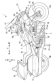
- FIG. 3 is a right side view of the vehicle 1 according to the embodiment
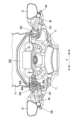
- FIG. 4 is a view of the vehicle 1 in the vehicle width direction as viewed from the driver P side.
- the arrows X, Y, and Z indicate mutually perpendicular directions, with the X direction indicating the front-rear direction of the vehicle (first direction), the Y direction indicating the vehicle width direction of the vehicle (left-right direction: second direction), and the Z direction indicating the up-down direction (third direction).
- the left and right of the vehicle are the left and right when viewed in the forward direction.
- the front or rear of the vehicle in the front-rear direction may be simply referred to as the front or rear.
- the inside or outside of the vehicle in the vehicle width direction (left-right direction) may be simply referred to as the inside or outside.
- Vehicle 1 is a touring motorcycle suitable for long-distance travel, but the present invention is applicable to various types of vehicles, including other types of motorcycles.
- the present invention is also applicable to vehicles such as EVs (Electric Vehicles) that run on an electric motor powered by power supplied from a battery, and FCVs (Fuel Cell Vehicles) that run on an electric motor powered by power supplied from a fuel cell.
- EVs Electric Vehicles
- FCVs Full Cell Vehicles
- the vehicle 1 is equipped with a power unit 2 between the front wheels FW and the rear wheels RW.
- the power unit 2 includes a drive source 21 and a transmission 22.
- the driving force of the transmission 22 is transmitted to the rear wheels RW via a drive shaft (not shown), rotating the rear wheels RW (drive wheels).
- the rotating shaft of the drive source 21 is mechanically connected to the rear wheels RW (drive wheels) of the vehicle 1 via a predetermined gear shift stage of the transmission 22.
- the power unit 2 is supported by a vehicle body frame 3.
- the vehicle body frame 3 includes a pair of left and right main frames 31 extending in the X direction.
- a display device 228 (meter panel) that displays various information to the driver P is provided above the main frames 31.
- a head pipe 32 is provided at the front end of the main frame 31, which rotatably supports a steering shaft (not shown) that is rotated by the throttle operator 8a (right handle lever) and the left handle lever 8b.
- a pair of left and right pivot plates 33 is provided at the rear end of the main frame 31. The lower ends of the pivot plates 33 are connected to the front end of the main frame 31 by a pair of left and right lower arms (not shown), and the power unit 2 is supported by the main frame 31 and the lower arms.
- a pair of left and right seat rails provided at the rear end of the main frame 31 support the seat 4a on which the driver P sits, the seat 4b on which the passenger sits, the rear trunk 7b, etc.
- Left and right saddlebags 7a are provided on the upper sides of the rear wheel RW.
- a front suspension mechanism 9 that supports the front wheel FW is configured at the front end of the main frame 31.
- the front suspension mechanism 9 includes an upper link 91, a lower link 92, a fork support 93, a cushion unit 94, and a pair of left and right front forks 95.
- the upper link 91 and the lower link 92 are arranged at a distance above and below the front end of the main frame 31.
- the front ends of the upper link 91 and the lower link 92 are connected to the fork support 93 so as to be able to swing freely.
- the upper link 91 and the lower link 92 each extend in the fore-and-aft direction and are arranged substantially parallel to each other.
- the cushion unit 94 has a structure in which a shock absorber is inserted into a coil spring, and its upper end is supported so as to be freely swingable by the main frame 31.
- the lower end of the cushion unit 94 is supported so as to be freely swingable by the lower link 92.
- the fork support 93 is cylindrical and tilted backward.
- the front end of the upper link 91 is rotatably connected to the upper front part of the fork support 93.
- the front end of the lower link 92 is rotatably connected to the lower rear part of the fork support 93.
- the steering shaft 96 is supported by the fork support 93 so as to be rotatable about its axis.
- the steering shaft 96 has an axle (not shown) that passes through the fork support 93.
- a bridge (not shown) is provided at the lower end of the steering shaft 96, and a pair of left and right front forks 95 are supported by this bridge.
- the front wheel FW is supported by the front fork 95 so as to be rotatable.
- the upper end of the steering shaft 96 is connected via a link 97 to a handlebar 11 (steering shaft) that is rotated by the throttle operator 8a (right handle lever) and the left handle lever 8b.
- the steering shaft 96 rotates by steering the throttle operator 8a (right handle lever) and the left handle lever 8b, and the front wheel FW is steered.
- the upper part of the front wheel FW is covered by a fender 10, which is supported by the front fork 95.
- the front of the vehicle 1 is covered by a front cover 12, and the front sides of the vehicle 1 are covered by a pair of left and right side covers 14.
- a screen 13 is disposed above the front cover 12.
- the screen 13 is a windshield that reduces the wind pressure experienced by the driver P while driving, and is formed, for example, from a transparent resin material.
- a pair of left and right side mirror units 15 are disposed on the sides of the front cover 12. The side mirror units 15 support side mirrors that allow the driver P to view the rear.
- the handlebars 11 are provided symmetrically with respect to the left-right center of the vehicle body (center in the vehicle width direction) and are made up of, for example, left and right handlebar members that are separate from each other.
- the handlebars 11 made up of the left and right handlebar members each extend diagonally upward from the upper end of the steering shaft 96 towards the left and right outside.
- the throttle operator 8a (right handlebar lever) and left handlebar lever 8b extend downward from the end of the handlebars 11 towards the rear and downward of the vehicle.
- the throttle operator 8a (right handlebar lever) and left handlebar lever 8b are each made up of a cylindrical member that extends in a straight line.
- a throttle operator 8a (right handlebar lever) is rotatably supported on the tip side (outside the left and right sides of the vehicle body) of the right handlebar 11.
- the vehicle 1 is equipped with a hydraulic brake device, and a front brake lever 16a, which is one operator of the brake device, is provided in front of the right throttle operator 8a.
- the vehicle 1 is also equipped with a hydraulic clutch device, and a clutch lever 16b, which is an operator of the clutch device, is provided in front of the left handlebar lever 8b on the left side.
- a housing 80 that rotatably holds the throttle operator 8a (right handle lever) is provided at the base end of the throttle operator 8a (right handle lever).
- Various handle switches 202 are provided on the housing 80.
- the throttle operator 8a (right handle lever) and the left handle lever 8b have a hollow structure, with a resin sleeve constituting the inner layer and a rubber grip body integrally attached to the outer periphery of the sleeve.
- An acquisition unit 221 is provided inside the throttle operator 8a (right handle lever) and the left handle lever 8b.
- the acquisition unit 221 may be configured to be located inside either the left or right handle lever. Alternatively, the acquisition unit 221 may be provided inside the combination switch or the housing 80 of the handle switch 202.
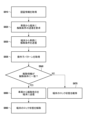
- (Processing flow 1 in communication system STM) 5 is a diagram illustrating a process flow in the communication system STM according to the embodiment.
- a process flow regarding a release determination based on the identification information of the vehicle 1 and the biometric information (authentication information) acquired from the accessory 240 (transmission device 250) as the release information is described.
- the acquisition unit 221 of the vehicle 1 acquires authentication information.
- This processing flow starts with the acquisition of authentication information by the equipment 240.
- the acquisition unit 221 acquires biometric information of the driver P as authentication information from the equipment 240 (transmission device 250) of the driver P via short-range wireless communication or an established communication link.
- the acquisition unit 221 also acquires identification information for identifying the vehicle 1 as release information from the memory unit 223 of the vehicle 1.
- the release information for determining whether to release the locked state of the terminal 230 also includes biometric information (authentication information).
- the communication unit 224 of the vehicle 1 transmits unlocking information to the terminal 230 in response to the acquisition of the authentication information by the acquisition unit 221, for determining whether or not to unlock the terminal 230.
- control unit 231 in the terminal 230 determines whether the release information received from the vehicle 1 via the communication unit 233 matches the release conditions stored in the memory unit 235.
- FIG. 6 is a diagram for explaining a process flow in the communication system STM according to the embodiment.
- the process flow 1 explained in Fig. 5 the process flow in which the control unit 231 of the terminal 230 makes a release determination is explained, but in Fig. 6, the process flow in which the control unit 222 of the vehicle 1 makes a release determination is explained.
- process flow 2 of FIG. 6 similar to process flow 1 of FIG. 5, the process flow for determining whether to release the vehicle 1 is based on the identification information of the vehicle 1 and the biometric information acquired from the equipment 240 (transmission device 250) as the release information is described.
- the acquisition unit 221 of the vehicle 1 acquires authentication information. This processing flow starts with the acquisition of authentication information by the equipment 240.
- the processing of S610 is similar to S510, and the acquisition unit 221 acquires biometric information of the driver P from the equipment 240 (transmission device 250) of the driver P as authentication information.
- the acquisition unit 221 also acquires identification information for identifying the vehicle 1 from the memory unit 223 of the vehicle 1 as release information.
- control unit 222 of the vehicle 1 transmits a request signal to the terminal 230 via the communication unit 224, requesting the transmission of the release conditions.
- the control unit 231 of the terminal 230 transmits the release conditions stored in the memory unit 235 to the vehicle 1 via the communication unit 233.
- control unit 222 in the vehicle 1 determines whether the release information acquired in S610 matches the release conditions received from the terminal 230.
- the control unit 231 of the terminal 230 releases the locked state of the terminal 230 based on the release instruction signal received from the vehicle 1 via the communication unit 233, making the terminal 230 available. In this case, the control unit 231 of the terminal 230 releases the locked state of the terminal 230 in response to receiving the release instruction signal, without determining whether the release information matches the release conditions. This makes it possible to reduce the processing load on the terminal 230.
- Process flow 3 in communication system STM is a diagram for explaining the flow of processing in the communication system STM according to the embodiment.
- process flow 3 of Fig. 7 the flow of processing related to release determination based on an operation pattern as release information will be explained.
- S710 the acquisition unit 221 of the vehicle 1 acquires authentication information. This processing flow begins with the acquisition of authentication information by the accessory 240. The processing of S710 is the same as S510.
- the acquisition unit 221 of the vehicle 1 acquires the operation pattern (first operation pattern) input by the driver P as release information.
- the communication unit 224 of the vehicle 1 transmits unlocking information to the terminal 230 in response to the acquisition of the authentication information by the acquisition unit 221, for determining whether or not to unlock the terminal 230.
- control unit 231 in the terminal 230 determines whether the release information received from the vehicle 1 via the communication unit 233 matches the release condition (first operation pattern) stored in the memory unit 235.
- FIG. 8 is a diagram for explaining a process flow in the communication system STM according to the embodiment.
- the process flow 3 explained in Fig. 7 the process flow in which the control unit 231 of the terminal 230 makes a release determination is explained, but in Fig. 8, a process flow in which the control unit 222 of the vehicle 1 makes a release determination is explained.
- a process flow related to a release determination based on an operation pattern as release information is explained.
- S810 the acquisition unit 221 of the vehicle 1 acquires authentication information. This processing flow begins with the acquisition of authentication information by the accessory 240. The processing of S810 is the same as S510.
- control unit 222 of the vehicle 1 transmits a request signal to the terminal 230 via the communication unit 224, requesting the transmission of the release conditions.
- the control unit 231 of the terminal 230 transmits the release condition (first operation pattern) stored in the memory unit 235 to the vehicle 1 via the communication unit 233.
- the acquisition unit 221 of the vehicle 1 acquires the operation pattern (first operation pattern) input by the driver P as release information.
- control unit 222 in the vehicle 1 determines whether the release information acquired in S835 matches the release conditions received from the terminal 230.
- control unit 222 of the vehicle 1 transmits a release instruction signal to the terminal 230 via the communication unit 224.
- the control unit 231 of the terminal 230 releases the locked state of the terminal 230 based on the release instruction signal received from the vehicle 1 via the communication unit 233, making the terminal 230 available. In this case, the control unit 231 of the terminal 230 releases the locked state of the terminal 230 in response to receiving the release instruction signal, without determining whether the release information matches the release conditions. This makes it possible to reduce the processing load on the terminal 230.
- control unit 222 of the vehicle 1 does not transmit an unlock instruction signal, and the control unit 231 of the terminal 230 maintains the locked state of the terminal 230 (S870).
- the control unit 222 of the vehicle 1 acquires the vehicle speed of the vehicle 1 measured by the vehicle speed measurement unit 211 at a predetermined time interval, and when the vehicle speed of the vehicle 1 reaches a traveling state equal to or higher than the predetermined vehicle speed, the control unit 222 restricts applications available on the terminal 230 while maintaining the unlocked state.
- the driver P can set in advance the applications to be available.
- the control unit 222 makes the applications set by the driver P available and sets the applications to a restricted available state in which the use of other applications is restricted. Based on the setting of the driver P, the control unit 222 allows only applications necessary for driving, such as a map application or a navigation application, to be available while restricting the use of other applications, thereby improving convenience while considering safety.
- the acquisition unit 221 of the vehicle 1 acquires authentication information from the equipment 240 of the driver P at predetermined time intervals, and if the acquired authentication information has been changed from the information stored in the storage unit 223, the control unit 222 sets the terminal 230 in a locked state in which it cannot be used.
- the acquisition unit 221 can acquire authentication information, for example, when the vehicle 1 is started or takes off, or at regular time intervals while the vehicle 1 is traveling.
- the control unit 222 sends a lock instruction to the terminal 230 via the communication unit 224, and the control unit 231 of the terminal 230 locks the terminal 230 based on the lock instruction received from the vehicle 1 via the communication unit 233. For example, even if the vehicle 1 and the terminal 230 are stolen, if the authentication information of a third party other than the driver P differs from the information pre-stored in the terminal, the terminal is locked and cannot be used, improving crime prevention.
- the control unit 222 of the vehicle 1 monitors the communication state between the vehicle 1 and the terminal 230 by the communication unit 224 while the terminal 230 is in the unlocked state. While the communication between the vehicle 1 and the terminal 230 continues, the control unit 222 maintains the unlocked state, and when the communication between the vehicle 1 and the terminal 230 ends, the control unit 222 returns the terminal 230 to a locked state in which it cannot be used.
- control unit 222 transmits a lock instruction to terminal 230 via communication unit 224, and control unit 231 of terminal 230 locks terminal 230 based on the lock instruction received from vehicle 1 via communication unit 233.
- control unit 231 of terminal 230 locks terminal 230 based on the lock instruction received from vehicle 1 via communication unit 233.
- the control unit 231 of the terminal 230 acquires an operation pattern (second operation pattern) input from an operator of the vehicle 1 within a predetermined time (first time) before and after a state in which the vehicle 1 is turned off, via the communication unit 233. Then, the control unit 231 compares the acquired operation pattern (second operation pattern) with information indicating the second operation pattern stored in the memory unit 235 of the terminal 230.
- the terminal 230 is made available for a predetermined time (second time) even after communication between the vehicle 1 and the terminal 230 has ended.
- the terminal when the vehicle is stopped at a gas station to refuel, the terminal can be operated for a certain period of time even after the power is turned off, allowing the device to be unlocked with the equipment attached. This makes it possible to improve convenience when using the terminal for payments at gas stations, etc.
- a program for realizing each function of the communication system described in the embodiment is supplied to a vehicle or a driver's terminal via a network or a storage medium, and one or more processors in a computer of the vehicle or the driver's terminal can read and execute the program.
- the present invention can also be realized in such an aspect.
- the communication system (STM) of the above embodiment includes a vehicle (1), A communication system (STM) having a driver's equipment (240) that provides authentication information for authenticating a driver to the vehicle (1), and a driver's terminal (230) having a communication unit (233) capable of communicating with the vehicle (1),
- the vehicle (1) An acquisition unit (221) that acquires the authentication information from the equipment;
- a control unit (220) having at least a processing unit (222) for processing the authentication information;
- a communication unit (224) capable of communicating with the terminal,
- the control unit (220) transmits release information for determining whether or not to release a lock state of the driver's terminal to the terminal via the communication unit in response to the acquisition of the authentication information by the acquisition unit;
- the terminal (230) unlocks the locked state of the terminal, making the terminal available for use.
- the communication system of configuration 1 allows the driver to unlock the terminal even when the equipment is attached.
- the vehicle's communication unit By using the vehicle's communication unit, it becomes unnecessary to provide equipment with dedicated communication devices for communication with terminals. This makes it possible to reduce the number of dedicated communication devices, reducing costs and improving convenience.
- the release information includes identification information for identifying the vehicle, A control unit (231) of the terminal (230) releases the locked state of the terminal (230) when the information stored in a storage unit (235) of the terminal matches the identification information.
- the vehicle identification information is used as unlocking information for unlocking the locked state, so that the driver can unlock the terminal without directly operating the terminal while driving the vehicle and wearing the accessory.
- the release information includes biometric information of the driver, A control unit (231) of the terminal (230) releases the locked state of the terminal (230) when the information stored in a storage unit (235) of the terminal matches the biometric information.
- the driver's biometric information (authentication information) obtained from the driver's equipment is used as unlocking information for unlocking the locked state, so that the driver can unlock the terminal without directly operating the terminal while wearing the equipment while driving the vehicle.
- the release information includes a first operation pattern input from an operator of the vehicle, A control unit (231) of the terminal (230) unlocks the terminal when the first operation pattern input from an operator of the vehicle matches information indicating the first operation pattern stored in a memory unit of the terminal.
- the first operation pattern input from the vehicle's operator is used as unlocking information for unlocking the locked state, so that the driver can unlock the terminal without directly operating the terminal while driving the vehicle and wearing the accessory.
- the control unit (231) of the terminal (230) acquires the vehicle speed of the vehicle measured by a vehicle speed measurement unit provided in the vehicle from the vehicle, When the vehicle speed reaches or exceeds a predetermined speed, a control unit (231) of the terminal (230) restricts applications that can be used on the terminal.
- the available applications are put into a restricted availability state, thereby achieving both convenience and safety.
- the apps that can be used in the limited availability state may be set in advance by the system or may be set by the user.
- apps that can be used in the limited availability state for example, only apps that are necessary for driving, such as map apps and navigation apps, can be used, which can improve convenience.
- the acquisition unit (221) acquires the authentication information at predetermined time intervals, and the control unit (231) of the terminal (230) locks the terminal so that it cannot be used if the authentication information is changed from the information stored in the storage unit of the terminal.
- the communication system of configuration 7 can provide a terminal state that matches the driver's intentions by using the end of communication between the vehicle and the terminal as a trigger to return to a locked state.
- the communication unit (224) transmits a second operation pattern input from an operator of the vehicle to the terminal within a predetermined time based on the state in which the vehicle is powered off, and the control unit of the terminal makes the terminal available for a predetermined time if the second operation pattern matches information stored in the memory unit of the terminal.
- the operation pattern input from the vehicle's controls within a specified time period is set as the unlocking condition for unlocking the locked state, based on the power-off state, so that the driver P can unlock the terminal while wearing the accessory without directly operating the terminal.
- the device when the vehicle is stopped at a gas station to fill up with gas, the device can be operated for a certain period of time even after the power is turned off, allowing the device to be unlocked with the accessories attached. This can improve convenience, for example, when making payments at gas stations.
- the communication system of the above embodiment includes an acquisition unit (221) that acquires authentication information from an equipment of the driver that provides authentication information for authenticating the driver to the vehicle; a vehicle communication unit (224) that acquires, in response to acquisition of the authentication information, an unlock condition of the terminal from the driver's terminal having a communication unit capable of communicating with the vehicle;
- the acquisition unit (221) In response to the acquisition of the authentication information, unlocking information for determining whether or not to unlock the driver's terminal is acquired from at least one of the authentication information or an operation element provided in the vehicle and operated by the driver to input; When the release information satisfies a release condition, a signal for instructing the unlocking of the locked state is output to the terminal via the vehicle communication unit.
- the driver can unlock the terminal while wearing the equipment.
- the vehicle's communication unit By using the vehicle's communication unit, it becomes unnecessary to provide equipment with dedicated communication devices for communication with terminals. This makes it possible to reduce the number of dedicated communication devices, reducing costs and improving convenience.
- the vehicle (1) of the above embodiment includes an acquisition unit (221) that acquires authentication information from an equipment of the driver that provides authentication information for authenticating the driver to the vehicle; A vehicle communication unit (224) capable of communicating with an external terminal, The acquisition unit (221) acquires, in response to acquisition of the authentication information, unlocking information for determining whether or not to unlock a terminal of the driver having a communication unit capable of communicating with the vehicle, from at least one of the authentication information or an operation element provided in the vehicle and operated by the driver to input an operation; The vehicle communication unit (224) transmits the release information to the terminal, When the unlocking information satisfies a predetermined unlocking condition, the terminal unlocks the terminal and makes the terminal available.
- the vehicle of the above embodiment includes an acquisition unit (221) that acquires authentication information from an equipment of the driver that provides authentication information for authenticating the driver to the vehicle; a vehicle communication unit (224) that acquires, in response to acquisition of the authentication information, a lock release condition of the terminal from the driver's terminal having a communication unit capable of communicating with the vehicle, via the communication unit;
- the acquisition unit (221) In response to the acquisition of the authentication information, unlocking information for determining whether or not to unlock the driver's terminal is acquired from at least one of the authentication information or an operation device provided in the vehicle and operated by the driver to input;
- the vehicle communication unit transmits the release information to the terminal, When the unlocking information satisfies a predetermined unlocking condition stored in a storage unit of the vehicle, an unlocking instruction signal for unlocking the terminal is output to the terminal via the vehicle communication unit.
- the driver can unlock the terminal while the accessory is installed.
- the vehicle's communication unit By using the vehicle's communication unit, it becomes unnecessary to provide equipment with dedicated communication devices for communication with terminals. This makes it possible to reduce the number of dedicated communication devices, reducing costs and improving convenience.
Landscapes
- Engineering & Computer Science (AREA)
- Theoretical Computer Science (AREA)
- Computer Security & Cryptography (AREA)
- Computer Hardware Design (AREA)
- Software Systems (AREA)
- Physics & Mathematics (AREA)
- General Engineering & Computer Science (AREA)
- General Physics & Mathematics (AREA)
- Computer Networks & Wireless Communication (AREA)
- Lock And Its Accessories (AREA)
Abstract
Description
前記装備品から前記認証情報を取得する取得部と、
前記認証情報を処理する処理部を少なくとも有する制御部と、
前記端末と通信可能な通信部と、を備え、
前記制御部は、前記取得部の前記認証情報の取得に応じて、前記運転者の端末のロック状態を解除するか否かを判定するための解除情報を、前記通信部を介して前記端末に送信させ、
前記端末は、受信した前記解除情報が解除条件を満たす場合に、前記端末のロック状態を解除して、当該端末を利用可能な状態にする。
図1は、実施形態に係る通信システムSTMの機能構成を示すブロック図である。図2は、通信システムSTMの構成を模式的に示す図である。図1に示すように通信システムSTMは、車両1と、車両1の運転者Pが所持するスマートフォン等の携帯型端末(以下、端末230)と、運転者Pが車両1を運転する際に装着する装備品240に搭載される伝送デバイス250と、を含む。端末230は、操作表示部234が車両1の後方に向けられた状態で不図示の保持部材により車両1に保持される。
装備品240は、例えば、グローブ241、スマートウォッチ242及びヘルメット243等が含まれる。また、装備品240は、ヘルメット243や運転者Pの頭部に装着される、マイク等により音声情報を入力可能なヘッドセット244であってもよい。
車両1の運転者Pが所持する端末230は、内部構成として、制御部231(認証部232、通信部233)、操作表示部234、記憶部235を有する。操作表示部234は、画面表示が可能なタッチパネル式のユーザインタフェースとして機能する。
車両1において、操作子200は、例示的な構成として、スロットル操作子8a、ハンドルスイッチ202(ハンドルSW)、及びイグニションスイッチ203(イグニションSW)を有する。
図3は、実施形態に係る車両1の右側の側面図、図4は運転者P側から見た車両1の車幅方向の図である。各図において、矢印X、Y、Zは互いに直交する方向を示し、X方向は車両の前後方向(第一方向)、Y方向は車両の車幅方向(左右方向:第二方向)、Z方向は上下方向(第三方向)を示す。車両の左、右は前進方向で見た場合の左、右である。以下、車両の前後方向の前方または後方のことを単に前方または後方と呼ぶ場合がある。また、車両の車幅方向(左右方向)の内側または外側のことを単に内側または外側と呼ぶことがある。
図5は実施形態に係る通信システムSTMにおける処理の流れを説明する図である。図5の処理フロー1では、解除情報として、車両1の識別情報や装備品240(伝送デバイス250)から取得した生体情報(認証情報)に基づいた解除判定に関する処理の流れを説明する。
図6は実施形態に係る通信システムSTMにおける処理の流れを説明する図である。図5で説明した処理フロー1では、端末230の制御部231が解除判定を行う処理の流れを説明したが、図6では、車両1の制御部222が解除判定を行う処理の流れを説明する。
図7は実施形態に係る通信システムSTMにおける処理の流れを説明する図である。図7の処理フロー3では、解除情報として、操作パターンに基づいた解除判定に関する処理の流れを説明する。
図8は実施形態に係る通信システムSTMにおける処理の流れを説明する図である。図7で説明した処理フロー3では、端末230の制御部231が解除判定を行う処理の流れを説明したが、図8では、車両1の制御部222が解除判定を行う処理の流れを説明する。図8の処理フロー4では、解除情報として、操作パターンに基づいた解除判定に関する処理の流れを説明する。
車両1の制御部222は、車速計測部211により計測された車両1の車速を所定時間間隔で取得し、車両1の車速が所定の車速以上の走行状態になった場合に、制御部222は、ロック解除状態を維持しつつ、端末230において利用可能なアプリケーションを制限する。運転者Pは、利用可能にするアプリケーションを予め設定することが可能である。制御部222は、運転者Pにより設定されたアプリケーションを利用可能な状態にし、その他のアプリケーションの利用を制限する制限付き利用可能状態にする。制御部222は、運転者Pの設定に基づいて、例えば、地図アプリやナビゲーションアプリなど、運転に必要なアプリのみを利用可能としつつその他のアプリの利用を制限することで安全性を考慮しながらも、利便性の向上を図ることが可能になる。
車両1の取得部221は、所定の時間間隔ごとに、運転者Pの装備品240から認証情報を取得し、取得した認証情報が、記憶部223に記憶された情報から変更された場合に、制御部222は、端末230を利用することができないロック状態にする。認証情報を取得するタイミングとして、取得部221は、例えば、車両1の始動時や発進時、走行中における一定時間間隔ごとに認証情報を取得することが可能である。
車両1の制御部222は、端末230のロック状態が解除された状態で、通信部224による車両1と端末230との間の通信状態を監視する。車両1と端末230との間の通信が継続している状態では、ロック解除状態を維持し、車両1と端末230との間の通信が終了した場合に、端末230を利用することができないロック状態に戻す。
端末230の制御部231は、車両1が電源オフにされた状態を基準として、前後の所定の時間内(第一の時間)に、車両1の操作子から入力された操作パターン(第二の操作パターン)を、通信部233を介して取得する。そして、制御部231は、取得した操作パターン(第二の操作パターン)と、端末230の記憶部235に記憶された第二の操作パターンを示す情報とを比較する。
また、実施形態で説明された通信システムの各機能を実現するプログラムは、ネットワーク又は記憶媒体を介して車両又は運転者の端末に供給され、車両又は運転者の端末のコンピュータにおける1以上のプロセッサは、このプログラムを読み出して実行することができる。このような態様によっても本発明は実現可能である。
上記実施形態は、少なくとも以下の通信システム及び車両を開示する。
前記車両(1)に運転者を認証するための認証情報を与える前記運転者の装備品(240)と、前記車両(1)と通信可能な通信部(233)を有する前記運転者の端末(230)と、を有する通信システム(STM)であって、
前記車両(1)は、
前記装備品から前記認証情報を取得する取得部(221)と、
前記認証情報を処理する処理部(222)を少なくとも有する制御部(220)と、
前記端末と通信可能な通信部(224)と、を備え、
前記制御部(220)は、前記取得部の前記認証情報の取得に応じて、前記運転者の端末のロック状態を解除するか否かを判定するための解除情報を、前記通信部を介して前記端末に送信させ、
前記端末(230)は、受信した前記解除情報が解除条件を満たす場合に、前記端末のロック状態を解除して、当該端末を利用可能な状態にする。
前記端末(230)の制御部(231)は、前記端末の記憶部(235)に記憶された情報と、前記識別情報とが一致する場合に、前記端末(230)のロック状態を解除する。
前記端末(230)の制御部(231)は、前記端末の記憶部(235)に記憶された情報と、前記生体情報とが一致する場合に、前記端末(230)のロック状態を解除する。
前記端末(230)の制御部(231)は、前記車両の操作子から入力された前記第一の操作パターンと、前記端末の記憶部に記憶された前記第一の操作パターンを示す情報とが一致する場合に、前記端末のロック状態を解除する。
前記車両の車速が所定の車速以上の走行状態になった場合に、前記端末(230)の制御部(231)は、前記端末において利用可能なアプリケーションを制限する。
前記認証情報の取得に応じて、前記車両と通信可能な通信部を有する前記運転者の端末から、前記端末のロック解除条件を取得する車両通信部(224)と、を備え、
前記取得部(221)は、
前記認証情報の取得に応じて、前記運転者の端末のロック状態を解除するか否かを判定するための解除情報を、前記認証情報又は前記車両に設けられた前記運転者が操作入力をする操作子の少なくとも一方から取得し、
前記解除情報が解除条件を満たす場合に、前記ロック状態の解除指示信号を、前記車両通信部を介して前記端末に出力する。
外部端末と通信可能な車両通信部(224)と、を備え、
前記取得部(221)は、前記認証情報の取得に応じて、前記車両と通信可能な通信部を有する前記運転者の端末のロック状態を解除するか否かを判定するための解除情報を、前記認証情報又は前記車両に設けられた前記運転者が操作入力をする操作子の少なくとも一方から取得し、
前記車両通信部(224)は、前記解除情報を前記端末に送信し、
前記端末は、前記解除情報が所定の解除条件を満たす場合に、前記端末のロック状態を解除して、当該端末を利用可能な状態にする。
前記認証情報の取得に応じて、前記車両と通信可能な通信部を有する前記運転者の端末から、通信部を介して、前記端末のロック解除条件を取得する車両通信部(224)と、を備え、
前記取得部(221)は、
前記認証情報の取得に応じて、前記運転者の端末のロック状態を解除するか否かを判定するための解除情報を、記認証情報又は前記車両に設けられた前記運転者が操作入力をする操作子の少なくとも一方から取得し、
前記車両通信部は、前記解除情報を前記端末に送信し、
前記解除情報が前記車両の記憶部に記憶された所定の解除条件を満たす場合に、前記端末のロック状態を解除させる解除指示信号を、前記車両通信部を介して前記端末に出力する。
210:計測装置、211:車速計測部、220:ECU、
221:取得部、222:制御部、223:記憶部、224:通信部、
230:端末、231:制御部、232:認証部、233:通信部、
234:操作表示部、235:記憶部、240:装備品、
251:生体情報取得部、252:記憶部、253:伝達部
Claims (11)
- 車両と、
前記車両に運転者を認証するための認証情報を与える前記運転者の装備品と、
前記車両と通信可能な通信部を有する前記運転者の端末と、を有する通信システムであって、
前記車両は、
前記装備品から前記認証情報を取得する取得部と、
前記認証情報を処理する処理部少なくとも有する制御部と、
前記端末と通信可能な通信部と、を備え、
前記制御部は、前記取得部の前記認証情報の取得に応じて、前記運転者の端末のロック状態を解除するか否かを判定するための解除情報を、前記通信部を介して前記端末に送信させ、
前記端末は、受信した前記解除情報が解除条件を満たす場合に、前記端末のロック状態を解除して、当該端末を利用可能な状態にする
通信システム。 - 前記解除情報には前記車両を特定するための識別情報が含まれ、
前記端末の制御部は、前記端末の記憶部に記憶された情報と、前記識別情報とが一致する場合に、前記端末のロック状態を解除する請求項1に記載の通信システム。 - 前記解除情報には前記運転者の生体情報が含まれ、
前記端末の制御部は、前記端末の記憶部に記憶された情報と、前記生体情報とが一致する場合に、前記端末のロック状態を解除する請求項1に記載の通信システム。 - 前記解除情報には前記車両の操作子から入力された第一の操作パターンが含まれ、
前記端末の制御部は、前記車両の操作子から入力された前記第一の操作パターンと、前記端末の記憶部に記憶された前記第一の操作パターンを示す情報とが一致する場合に、前記端末のロック状態を解除する請求項1に記載の通信システム。 - 前記端末の制御部は、前記車両に設けられた車速計測部により計測された前記車両の車速を前記車両より取得し、
前記車両の車速が所定の車速以上の走行状態になった場合に、前記端末の制御部は、前記端末において利用可能なアプリケーションを制限する請求項1に記載の通信システム。 - 前記取得部は、所定の時間間隔ごとに前記認証情報を取得し、
前記端末の制御部は、前記認証情報が、前記端末の記憶部に記憶されている情報から変更された場合に、前記端末を利用することができないロック状態にする請求項1乃至5のいずれか1項に記載の通信システム。 - 前記端末の制御部は、前記端末のロック状態が解除された状態で、前記通信部と前記端末との間の通信が終了した場合に、前記端末を利用することができないロック状態に戻す請求項1に記載の通信システム。
- 前記通信部は、前記車両が電源オフにされた状態を基準として所定の時間内に、前記車両の操作子から入力された第二の操作パターンを前記端末へ送信し、前記端末の制御部は、前記端末の記憶部に記憶された前記第二の操作パターンを示す情報とが一致する場合に、予め定められた時間だけ前記端末を利用可能な状態にする請求項7に記載の通信システム。
- 車両に運転者を認証するための認証情報を与える前記運転者の装備品から、前記認証情報を取得する取得部と、
前記認証情報の取得に応じて、前記車両と通信可能な通信部を有する前記運転者の端末から、前記端末のロック解除条件を取得する車両通信部(224)と、を備え、
前記取得部は、
前記認証情報の取得に応じて、前記運転者の端末のロック状態を解除するか否かを判定するための解除情報を、前記認証情報又は前記車両に設けられた前記運転者が操作入力をする操作子の少なくとも一方から取得し、
前記解除情報が解除条件を満たす場合に、前記ロック状態の解除指示信号を、前記車両通信部を介して前記端末に出力する通信システム。 - 車両に運転者を認証するための認証情報を与える前記運転者の装備品から、前記認証情報を取得する取得部と、
外部端末と通信可能な車両通信部と、を備え、
前記取得部は、前記認証情報の取得に応じて、前記車両と通信可能な通信部を有する前記運転者の端末のロック状態を解除するか否かを判定するための解除情報を、前記認証情報又は前記車両に設けられた前記運転者が操作入力をする操作子の少なくとも一方から取得し、
前記車両通信部は、前記解除情報を前記端末に送信し、
前記端末は、前記解除情報が所定の解除条件を満たす場合に、前記端末のロック状態を解除して、当該端末を利用可能な状態にする車両。 - 車両に運転者を認証するための認証情報を与える前記運転者の装備品から、前記認証情報を取得する取得部と、
前記認証情報の取得に応じて、前記車両と通信可能な通信部を有する前記運転者の端末から、通信部を介して、前記端末のロック解除条件を取得する車両通信部と、を備え、
前記取得部は、
前記認証情報の取得に応じて、前記運転者の端末のロック状態を解除するか否かを判定するための解除情報を、記認証情報又は前記車両に設けられた前記運転者が操作入力をする操作子の少なくとも一方から取得し、
前記車両通信部は、前記解除情報を前記端末に送信し、
前記解除情報が前記車両の記憶部に記憶された所定の解除条件を満たす場合に、前記端末のロック状態を解除させる解除指示信号を、前記車両通信部を介して前記端末に出力する車両。
Priority Applications (1)
| Application Number | Priority Date | Filing Date | Title |
|---|---|---|---|
| JP2024552844A JPWO2024089985A1 (ja) | 2022-10-28 | 2023-08-18 |
Applications Claiming Priority (2)
| Application Number | Priority Date | Filing Date | Title |
|---|---|---|---|
| JP2022173616 | 2022-10-28 | ||
| JP2022-173616 | 2022-10-28 |
Publications (1)
| Publication Number | Publication Date |
|---|---|
| WO2024089985A1 true WO2024089985A1 (ja) | 2024-05-02 |
Family
ID=90830416
Family Applications (1)
| Application Number | Title | Priority Date | Filing Date |
|---|---|---|---|
| PCT/JP2023/029847 Ceased WO2024089985A1 (ja) | 2022-10-28 | 2023-08-18 | 通信システム及び車両 |
Country Status (2)
| Country | Link |
|---|---|
| JP (1) | JPWO2024089985A1 (ja) |
| WO (1) | WO2024089985A1 (ja) |
Citations (5)
| Publication number | Priority date | Publication date | Assignee | Title |
|---|---|---|---|---|
| JP2000078279A (ja) * | 1998-09-01 | 2000-03-14 | Alpine Electronics Inc | 車載電話のダイヤルロック解除システム及びキーレスユニット |
| JP2005269211A (ja) * | 2004-03-18 | 2005-09-29 | Hitachi Software Eng Co Ltd | 携帯電話機の機能ロック装置および携帯電話機 |
| JP2007104146A (ja) * | 2005-09-30 | 2007-04-19 | Tokai Rika Co Ltd | リモートコントローラー |
| JP2007233590A (ja) * | 2006-02-28 | 2007-09-13 | Oki Electric Ind Co Ltd | 携帯型電子装置、個人認証システム、個人認証方法、及び半導体装置の製造方法 |
| JP2019182013A (ja) * | 2018-04-03 | 2019-10-24 | 株式会社デンソー | 表示制限システム、およびメータ装置 |
Family Cites Families (2)
| Publication number | Priority date | Publication date | Assignee | Title |
|---|---|---|---|---|
| KR102096613B1 (ko) * | 2018-08-31 | 2020-04-06 | 금오공과대학교 산학협력단 | 도난방지 기능이 적용된 오토바이 헬맷 착용 감지 시스템 |
| JP7590956B2 (ja) * | 2019-03-22 | 2024-11-27 | フェリカネットワークス株式会社 | 情報処理装置、情報処理システム、および情報処理方法、並びにプログラム |
-
2023
- 2023-08-18 WO PCT/JP2023/029847 patent/WO2024089985A1/ja not_active Ceased
- 2023-08-18 JP JP2024552844A patent/JPWO2024089985A1/ja active Pending
Patent Citations (5)
| Publication number | Priority date | Publication date | Assignee | Title |
|---|---|---|---|---|
| JP2000078279A (ja) * | 1998-09-01 | 2000-03-14 | Alpine Electronics Inc | 車載電話のダイヤルロック解除システム及びキーレスユニット |
| JP2005269211A (ja) * | 2004-03-18 | 2005-09-29 | Hitachi Software Eng Co Ltd | 携帯電話機の機能ロック装置および携帯電話機 |
| JP2007104146A (ja) * | 2005-09-30 | 2007-04-19 | Tokai Rika Co Ltd | リモートコントローラー |
| JP2007233590A (ja) * | 2006-02-28 | 2007-09-13 | Oki Electric Ind Co Ltd | 携帯型電子装置、個人認証システム、個人認証方法、及び半導体装置の製造方法 |
| JP2019182013A (ja) * | 2018-04-03 | 2019-10-24 | 株式会社デンソー | 表示制限システム、およびメータ装置 |
Also Published As
| Publication number | Publication date |
|---|---|
| JPWO2024089985A1 (ja) | 2024-05-02 |
Similar Documents
| Publication | Publication Date | Title |
|---|---|---|
| CN114556407A (zh) | 安全集成共享车辆系统和方法 | |
| JP5197936B2 (ja) | 車両制御装置およびそれを備えた車両 | |
| JP2002243591A (ja) | 車両用故障診断装置 | |
| KR20040027338A (ko) | 자동 이륜차의 도난 방지 장치 | |
| EP3461700A1 (en) | Saddle-type vehicle | |
| JP2008310766A (ja) | イベントデータレコーダ、自動二輪車及び情報記録方法 | |
| JP2023508399A (ja) | 車両に音声コマンドを伝達するための方法及びシステム | |
| TW201936440A (zh) | 控制裝置及控制系統 | |
| JP6987127B2 (ja) | オープンキャビンビークル | |
| JP2008179274A (ja) | 車両用盗難防止装置 | |
| WO2024089985A1 (ja) | 通信システム及び車両 | |
| JP2014119657A (ja) | 運転操作装置及び仮想運転システム | |
| US9656718B2 (en) | Saddle riding type vehicle | |
| US20250065842A1 (en) | On-vehicle communication system, saddle riding vehicle, and program | |
| JP2007238058A (ja) | 車両用スマートエントリシステム | |
| JP4745180B2 (ja) | レジャービィークル用電子キーシステム | |
| US6879241B2 (en) | Vehicle ready for card key and radio communication system which utilizes card key | |
| CN114450218A (zh) | 骑乘型车辆的车辆信息报告装置 | |
| JP7634986B2 (ja) | 管理システム、管理装置、管理方法、および、コンピュータプログラム | |
| CN217778859U (zh) | 摩托车 | |
| JP2023070467A (ja) | 人力駆動車用制御装置、人力駆動車の制御システム、人力駆動車の制御方法、および、コンピュータプログラム | |
| CN217778860U (zh) | 摩托车 | |
| JP2009061957A (ja) | イモビライザ | |
| KR101971527B1 (ko) | 전기 자전거 및 그 제어방법 | |
| JP7531629B2 (ja) | 車両、車載機器、およびプログラム |
Legal Events
| Date | Code | Title | Description |
|---|---|---|---|
| 121 | Ep: the epo has been informed by wipo that ep was designated in this application |
Ref document number: 23882201 Country of ref document: EP Kind code of ref document: A1 |
|
| WWE | Wipo information: entry into national phase |
Ref document number: 2024552844 Country of ref document: JP |
|
| WWE | Wipo information: entry into national phase |
Ref document number: 202547047356 Country of ref document: IN |
|
| NENP | Non-entry into the national phase |
Ref country code: DE |
|
| WWP | Wipo information: published in national office |
Ref document number: 202547047356 Country of ref document: IN |
|
| 122 | Ep: pct application non-entry in european phase |
Ref document number: 23882201 Country of ref document: EP Kind code of ref document: A1 |