WO2024089949A1 - 車載通信システム、制御装置および電気装置 - Google Patents
車載通信システム、制御装置および電気装置 Download PDFInfo
- Publication number
- WO2024089949A1 WO2024089949A1 PCT/JP2023/025716 JP2023025716W WO2024089949A1 WO 2024089949 A1 WO2024089949 A1 WO 2024089949A1 JP 2023025716 W JP2023025716 W JP 2023025716W WO 2024089949 A1 WO2024089949 A1 WO 2024089949A1
- Authority
- WO
- WIPO (PCT)
- Prior art keywords
- power
- unit
- communication
- electric
- control device
- Prior art date
- Legal status (The legal status is an assumption and is not a legal conclusion. Google has not performed a legal analysis and makes no representation as to the accuracy of the status listed.)
- Ceased
Links
Images





Classifications
-
- B—PERFORMING OPERATIONS; TRANSPORTING
- B60—VEHICLES IN GENERAL
- B60R—VEHICLES, VEHICLE FITTINGS, OR VEHICLE PARTS, NOT OTHERWISE PROVIDED FOR
- B60R16/00—Electric or fluid circuits specially adapted for vehicles and not otherwise provided for; Arrangement of elements of electric or fluid circuits specially adapted for vehicles and not otherwise provided for
- B60R16/02—Electric or fluid circuits specially adapted for vehicles and not otherwise provided for; Arrangement of elements of electric or fluid circuits specially adapted for vehicles and not otherwise provided for electric constitutive elements
- B60R16/023—Electric or fluid circuits specially adapted for vehicles and not otherwise provided for; Arrangement of elements of electric or fluid circuits specially adapted for vehicles and not otherwise provided for electric constitutive elements for transmission of signals between vehicle parts or subsystems
-
- H—ELECTRICITY
- H04—ELECTRIC COMMUNICATION TECHNIQUE
- H04L—TRANSMISSION OF DIGITAL INFORMATION, e.g. TELEGRAPHIC COMMUNICATION
- H04L12/00—Data switching networks
- H04L12/28—Data switching networks characterised by path configuration, e.g. LAN [Local Area Networks] or WAN [Wide Area Networks]
Definitions
- This disclosure relates to an in-vehicle communication system, a control device, and an electrical device.
- This application claims priority to Japanese Application No. 2022-171949, filed on October 27, 2022, and incorporates all of the contents of said Japanese application by reference.
- various installed electrical devices e.g., cameras, sensors, and car navigation systems
- an on-board battery For example, in a PHEV (Plug-in Hybrid Electric Vehicle) or EV (Electric Vehicle), the output voltage of the high-voltage battery used to drive the motor is converted to an appropriate voltage by a power conversion device and supplied to the electrical devices inside the vehicle.
- PHEV Plug-in Hybrid Electric Vehicle
- EV Electric Vehicle
- Patent Document 1 discloses a data communications system that determines whether or not to supply power by taking into account the supply capacity of the power supplier and the capacity of the power receiver.
- An in-vehicle communication system is an in-vehicle communication system including a first control device and a plurality of first electric devices, the first control device including a first power supply unit that outputs electric power, a plurality of first communication units corresponding to each of the plurality of first electric devices, a plurality of first communication paths corresponding to each of the plurality of first communication units, and a first priority determination unit that determines a first priority for supplying electric power from the first power supply unit to the plurality of first electric devices, the first priority determination unit transmits a first transmission request from the plurality of first communication units to each of the plurality of first electric devices via the plurality of first communication paths, and in response to the first transmission request, each of the plurality of first electric devices transmits information representing the importance and required power of the first electric device to the first control device via the first communication path, and the first priority determination unit determines the first priority based on the information representing the importance and required power received from the plurality of first electric devices.
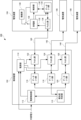
- FIG. 1 is a block diagram showing a configuration of an in-vehicle communication system according to a first embodiment of the present disclosure.
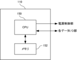
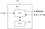
- FIG. 2 is a block diagram showing a configuration of the priority determination unit shown in FIG.
- FIG. 3 is a block diagram showing the configuration of the PoDL (Power over Data Line) section shown in FIG. 1.
- FIG. 4 is a block diagram showing the configuration of the control unit of the electrical device shown in FIG.
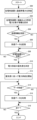
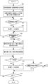
- FIG. 5 is a flowchart showing a process executed by the control device shown in FIG.
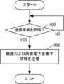
- FIG. 6 is a flow chart illustrating the process performed by the electrical device shown in FIG.
- FIG. 7 is a flowchart showing a process executed by the control device according to the first modified example.
- FIG. 8 is a block diagram showing the configuration of an in-vehicle communication system according to the second embodiment.
- FIG. 9 is a block diagram showing a configuration of the priority determination unit of the second control device shown in FIG.
- FIG. 10 is a block diagram showing the configuration of a control unit of an electric device connected to the first control unit and the second control unit shown in FIG.
- FIG. 11 is a flowchart showing the process executed by the first control device shown in FIG.
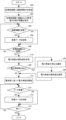
- FIG. 12 is a flowchart showing the process executed by the second control device shown in FIG.
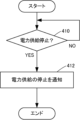
- FIG. 13 is a flowchart showing a process executed by an electric device according to the second modification.
- the present disclosure aims to provide an in-vehicle communication system, a control device, and an electrical device that can supply power preferentially to an electrical device having a specific function based on the importance of each electrical device among multiple electrical devices installed in a vehicle.
- a vehicle-mounted communication system includes a first control device and a plurality of first electric devices
- the first control device includes a first power supply unit that outputs electric power, a plurality of first communication units corresponding to each of the plurality of first electric devices, a plurality of first communication paths corresponding to each of the plurality of first communication units, and a first priority determination unit that determines a first priority for supplying electric power from the first power supply unit to the plurality of first electric devices
- the first priority determination unit transmits a first transmission request from the plurality of first communication units to each of the plurality of first electric devices via the plurality of first communication paths
- each of the plurality of first electric devices transmits information representing the importance and required power of the first electric device to the first control device via the first communication path in response to the first transmission request
- the first priority determination unit determines the first priority based on the information representing the importance and required power received from the plurality of first electric devices. This allows power to be preferentially supplied to an electric device having a
- the first power supply unit can supply the first electric devices with communication power required for each of the first electric devices to communicate with the first control device via the first communication paths. This makes it possible to reduce unnecessary power consumption.
- the first control device may further include at least one superimposing unit of the multiple first communication units, and the superimposing unit may generate a superimposed signal by superimposing the communication signal output from the first communication unit and the power supplied from the first power supply unit, and output the superimposed signal to a first communication path corresponding to the first communication unit that output the communication signal, or may separate a signal including information indicating the importance and required power from a transmission signal transmitted from the first electric device via the first communication path, and output the separated information to the first priority determination unit via the first communication unit corresponding to the first electric device that output the transmission signal.
- This allows power to be superimposed on the communication line transmitting the communication signal and supplied to the electric device. Therefore, the number of electric wirings can be reduced.
- each of the multiple first electric devices may include a separation unit that separates a signal including a first transmission request from a superimposed signal transmitted via a first communication path corresponding to the first electric device, and a communication unit that transmits information representing the importance and required power of the first electric device to the first control device via the first communication path in response to the first transmission request separated by the separation unit. This allows the first control device to receive information representing the importance and required power of each of the multiple first electric devices, making it possible to determine the first priority.
- the separation unit may further separate power from the superimposed signal transmitted via the first communication path corresponding to the first electric device, and each of the first electric devices may further include a power receiving unit that initially supplies the power separated by the separation unit to the communication unit. This enables the first electric device to transmit information indicating the importance and required power as a reply to a transmission request from the first control device.
- the first priority determination unit may change the first priority depending on the state of the vehicle in which the in-vehicle communication system is installed. This allows an appropriate priority to be determined depending on the state of the vehicle. The importance of each electrical device installed in the vehicle changes depending on the state of the vehicle. Therefore, power can be supplied preferentially to an electrical device having a specific function depending on the state of the vehicle.
- the in-vehicle communication system may further include a second control device and a plurality of second electric devices, at least one of the plurality of first electric devices being a specific electric device
- the second control device may include a second power supply unit that outputs electric power, a plurality of second communication units corresponding to each of the plurality of second electric devices and the specific electric device, a plurality of second communication paths corresponding to each of the plurality of second communication units, and a second priority determination unit that determines a second priority for supplying electric power from the second power supply unit to the plurality of second electric devices and the specific electric device, and the second priority determination unit may determine a second priority for supplying electric power from the second power supply unit to the plurality of second electric devices and the specific electric device
- the second control unit may transmit a second transmission request to each of the second electric devices via the second communication paths, and each of the second electric devices may transmit information representing the importance and required power of the second electric device to the second control unit via the second communication paths in
- the second priority determination unit may determine the second priority based on the information representing the importance and required power received from the second electric devices. In response to a reduction in the power supplied from the first power supply unit to the specific electric device, the second priority determination unit may change the second priority so that power is supplied from the second power supply unit to the specific electric device. This makes it possible to supply power to the specific electric device even when the power supplied from the first control unit to the specific electric device is reduced, and the specific electric device can maintain its function.
- the first priority determination unit may notify the second priority determination unit of information indicating that the power supplied from the first power supply unit to the specific electrical device is to be reduced. This allows the second control device to efficiently start supplying power to the specific electrical device when the power supplied from the first control device to the specific electrical device is reduced.
- the specific electrical device may notify the second priority determination unit of information indicating that the power supplied from the first power supply unit to the specific electrical device will be reduced. This allows the second control device to efficiently start supplying power to the specific electrical device when the power supplied from the first control device to the specific electrical device is reduced.
- the information indicating that power will be reduced may include information indicating the importance and power requirements of the specific electrical device. This allows the second control device to quickly change the priority so that power can be supplied to the specific electrical device.
- a control device is a control device mounted on a vehicle, and includes a power supply unit that outputs electric power, a plurality of communication units, and a priority determination unit that determines a priority for supplying electric power from the power supply unit to a plurality of electric devices mounted on the vehicle corresponding to each of the plurality of communication units via a plurality of communication paths corresponding to each of the plurality of communication units, the priority determination unit transmits a transmission request to each of the plurality of electric devices from the plurality of communication units via the plurality of communication paths, and receives, in response to the transmission request, information representing the importance and required power of the electric device from each of the plurality of electric devices via the communication path, and the priority determination unit determines the priority based on the information representing the importance and required power received from the plurality of electric devices. This allows electric power to be supplied from the control device to the plurality of electric devices mounted on the vehicle based on the importance of each electric device.
- a control device is a control device mounted on a vehicle, the control device including a power supply unit that outputs electric power, a plurality of communication units, and a priority determination unit that determines a priority of supplying electric power from the power supply unit to a plurality of electric devices mounted on the vehicle via a plurality of communication paths corresponding to each of the plurality of communication units, at least one of the plurality of electric devices is designated as a specific electric device, the priority determination unit transmits a transmission request from the plurality of communication units via the plurality of communication paths to an electric device other than the specific electric device, and receives information representing the importance and required power of the electric device from the electric device other than the specific electric device in response to the transmission request via the communication path, the priority determination unit determines a priority based on the information representing the importance and required power received from the electric device other than the specific electric device, and in response to a reduction in power supplied to the specific electric device from an on-board device other than the control device, the priority determination unit
- An electric device is an electric device mounted on a vehicle, and includes a separation unit that separates a communication signal from a superimposed signal on which power and a communication signal are superimposed and transmitted from a control device mounted on the vehicle via a communication path, and a communication unit that transmits information representing the importance and required power of the electric device to the control device via the communication path in response to a transmission request included in the communication signal. This allows the control device to supply power to multiple electric devices mounted on the vehicle based on the importance of each electric device.
- the separation unit may further include a power receiving unit that further separates power from the superimposed signal transmitted via the communication path and first supplies the power separated by the separation unit to the communication unit. This enables the electrical device to transmit information indicating the importance and required power.
- the electric device may further include a separation unit separate from the separation unit that receives power from an on-board device separate from the control device, which is mounted on the vehicle, via a path separate from the communication path in response to a reduction in the power supplied from the control device, and the separate separation unit may separate power from a superimposed signal in which the power supplied from the on-board device via the separate path is superimposed on the communication signal, and output the power to the power receiving unit.
- an in-vehicle communication system 100 includes a control device 102 and electric devices 104, 106, and 108.
- the in-vehicle communication system 100 is mounted on a vehicle (not shown).
- the control device 102 is, for example, a C-ECU (Central-Electronic Control Unit).
- Each of the electric devices 104, 106, and 108 is an in-vehicle camera, a sensor, a car navigation system, or the like, and is a target to which power is supplied from the control device 102.
- the control device 102 and the electric devices 104, 106, and 108 are communicatively connected by communication lines 140, 142, and 144, respectively.
- Each communication line constitutes a communication path for connecting the electric devices and the control unit. Note that, although three electric devices are shown in FIG. 1, this is not limiting.
- the control device 102 may be connected to two electric devices so as to be able to supply power. Additionally, the control device 102 may be connected to supply power to four or more electrical devices.
- the control device 102 includes a priority determination unit 110, a power supply control unit 112, a power supply unit 114, data I/O units 116, 118, and 120, and PoDL units 122, 124, and 126. As described below, each data I/O unit and its corresponding PoDL unit constitute a communication unit for the control device 102 to communicate with each electric device.
- the priority determination unit 110 includes a CPU (Central Processing Unit) 150 and a memory 152.
- the CPU 150 controls the memory 152.
- the memory 152 is, for example, a rewritable non-volatile semiconductor memory, and stores a computer program (hereinafter simply referred to as a program) executed by the CPU 150.
- the CPU 150 stores the results of the executed processing in the memory 152 as appropriate.
- CPU 150 outputs data input from data I/O units 116, 118, and 120 to memory 152 for storage.
- CPU 150 also reads out data from memory 152 to be output from priority determination unit 110 to power supply control unit 112 and data I/O units 116, 118, and 120, and outputs the data.
- the priority determination unit 110 determines the priority of supplying power from the control device 102 to the electrical devices 104, 106, and 108, and outputs information indicating the priority determined by the determination (hereinafter referred to as priority information) to the power supply control unit 112.
- the power supply control unit 112 outputs information indicating the value of the power output from the multiple ports of the power supply unit 114 (hereinafter referred to as output power information) to the power supply unit 114 in accordance with the priority information input from the priority determination unit 110.
- the power supply unit 114 outputs the indicated amount of power (i.e., DC power) from each output port in accordance with the output power information input from the power supply control unit 112.
- the three output ports of the power supply unit 114 are connected to the PoDL units 122, 124, and 126, respectively, and the output power of the power supply unit 114 is input to the PoDL units 122, 124, and 126.
- the power output by the power supply unit 114 is generated from external power (power necessary for the operation of the control device 102, for example, power obtained by converting the voltage of an on-board battery (not shown) to a predetermined voltage) supplied from outside the control device 102.
- Priority determination unit 110 acquires specific information for determining the above-mentioned priority from electrical devices 104, 106, and 108. To this end, priority determination unit 110 outputs an instruction requesting the specific information (e.g., specific code data, hereinafter referred to as a transmission request) via data I/O units 116, 118, and 120.
- the specific information is information that represents the function and required power of each electrical device.
- Required power means the power required to operate the electrical device. The required power is, for example, the rated value of the power consumption of each electrical device, and can be acquired from the specifications or instruction manual of each electrical device. The required power may be determined from the power consumption measured by operating each electrical device.
- Data I/O units 116, 118, and 120 output a communication signal corresponding to the transmission request input from priority determination unit 110.
- Data I/O units 116, 118, and 120 are connected to PoDL units 122, 124, and 126, respectively, and communication signals (i.e., transmission requests) output from data I/O units 116, 118, and 120 are input to PoDL units 122, 124, and 126.
- Each of the PoDL units 122, 124, and 126 functions as a signal superposition unit. That is, the PoDL unit 122 generates a signal (hereinafter referred to as a superposition signal) by superimposing a communication signal (e.g., a transmission request) input from the data I/O unit 116 and DC power input from the power supply unit 114, and outputs the signal to the communication line 140. Similarly, the PoDL unit 124 superimposes a communication signal (e.g., a transmission request) input from the data I/O unit 118 and DC power input from the power supply unit 114, and outputs the superposition signal to the communication line 142. The PoDL unit 126 superimposes a communication signal (e.g., a transmission request) input from the data I/O unit 120 and DC power input from the power supply unit 114, and outputs the superposition signal to the communication line 144.
- a communication signal e.g., a transmission request
- Each of the PoDL units 122, 124, and 126 includes, for example, a bias tee.
- the PoDL unit 122 includes a capacitor C1 arranged between the terminals T1 and T3, and an inductor L1 arranged between the terminals T2 and T3.
- a communication signal i.e., an AC signal
- a DC power i.e., a DC signal
- a signal in which the AC signal is superimposed on the DC component is output from the terminal T3.
- Each of the PoDL units 122, 124, and 126 is not limited to a circuit using a capacitor and an inductor, and may be configured as a distributed constant circuit using a stub.
- the communication lines 140, 142, and 144 are realized, for example, by a coaxial cable or a twisted pair cable for transmitting a differential signal.
- Each of the PoDL units 122, 124, and 126 also functions as a signal separator. That is, the PoDL unit 122 separates the AC component from the communication signal input via the communication line 140 (i.e., a signal biased with DC power from the power supply unit 114) and outputs it to the data I/O unit 116.
- the PoDL unit 122 separates the AC component from the communication signal input via the communication line 140 (i.e., a signal biased with DC power from the power supply unit 114) and outputs it to the data I/O unit 116.
- the communication signal input to the PoDL unit 122 via the communication line 140 is input to the terminal T3
- the AC component is output from the terminal T1.
- the output from the terminal T1 is input to the data I/O unit 116, which generates digital data and outputs it to the priority determination unit 110.
- the PoDL unit 124 separates the AC component from the communication signal input via the communication line 142 and outputs it to the data I/O unit 118.
- the data I/O unit 118 generates digital data and outputs it to the priority determination unit 110.
- the PoDL unit 126 separates the AC component from the communication signal input via the communication line 144 and outputs it to the data I/O unit 120.
- the data I/O unit 120 generates digital data and outputs it to the priority determination unit 110. This allows the priority determination unit 110 to receive data transmitted from the electrical devices 104, 106, and 108.
- the PoDL unit 122 is connected to the PoDL unit 136 of the electrical device 104 via a communication line 140, and the superimposed signal output from the PoDL unit 122 is transmitted to the PoDL unit 136 via the communication line 140.
- the PoDL unit 124 is connected to the PoDL unit of the electrical device 106 via a communication line 142, and the superimposed signal output from the PoDL unit 124 is transmitted to the PoDL unit of the electrical device 106 via the communication line 142.
- the PoDL unit 126 is connected to the PoDL unit of the electrical device 108 via a communication line 144, and the superimposed signal output from the PoDL unit 126 is transmitted to the PoDL unit of the electrical device 108 via the communication line 144.
- the electric device 104 includes a control unit 130, a power receiving unit 132, a data I/O unit 134, a PoDL unit 136, a functional unit 138, and a switch 139.
- the functional unit 138 is an element for realizing the functions of the electric device 104.
- the electric devices 106 and 108 also include the same elements as the electric device 104. However, the functional units, which are elements for realizing the respective functions of the electric devices 106 and 108, may be different from the functional unit 138 of the electric device 104.
- the PoDL unit 136 functions as a separator, similar to the PoDL unit 122. That is, the PoDL unit 136 separates the input signal (i.e., a signal biased with DC power from the power supply unit 114) into an AC component and a DC component and outputs them. The separated AC component is input to the data I/O unit 134, and the separated DC component is input to the power receiving unit 132.
- the PoDL unit 136 is configured similarly to the PoDL unit 122.
- the PoDL unit 136 includes, for example, a bias T. When the superimposed signal input from the communication line 140 to the PoDL unit 136 is input to terminal T3 (see FIG. 3), an AC component is output from terminal T1, and a DC component is output from terminal T2. The output from terminal T1 is input to data I/O unit 134, and the output from terminal T2 is input to power receiving unit 132.
- the power receiving unit 132 receives the DC component separated by the PoDL unit 136, i.e., DC power, and first supplies the input DC power to the data I/O unit 134 and the control unit 130. This allows the control unit 130 and the data I/O unit 134 to function, and as described below, the data I/O unit 134 and the control unit 130 can receive communication signals transmitted via the communication line 140. The control unit 130 and the data I/O unit 134 can also output communication signals to the communication line 140. If the power supplied from the PoDL unit 136 is sufficient to execute the function of the electric device 104, the power receiving unit 132 also supplies power to the function unit 138, which is an element for executing the function. As described below, as a result of the communication, the control unit 130 controls the on/off of the switch 139 to control the power supply from the power receiving unit 132 to the function unit 138.
- the data I/O unit 134 receives the AC components separated by the PoDL unit 136, i.e., the communication signals, generates digital data from the input communication signals, and outputs the data to the control unit 130.
- the data I/O unit 134 operates according to the same communication specifications as the data I/O unit 116.
- control unit 130 includes a CPU 160 and a memory 162.
- CPU 160 controls memory 162.
- Memory 162 is, for example, a rewritable non-volatile semiconductor memory, and stores the program executed by CPU 160.
- CPU 160 stores the results of the executed processing in memory 162 as appropriate.
- CPU 160 outputs data input from data I/O unit 134 to memory 162 for storage.
- CPU 160 also reads data to be output to data I/O unit 134 from memory 162, and outputs the data to data I/O unit 134. If the data input from data I/O unit 134 to CPU 160 is an instruction to control unit 130 (for example, the above-mentioned transmission request), CPU 160 executes the instructed processing and outputs the result to data I/O unit 134.
- the CPU 160 reads information (i.e., the specified information) representing the function and power requirements of the electric device 104 stored in the memory 162, and outputs it to the data I/O unit 134.
- the processing result i.e., the specified information
- the reason for transmitting the information representing the function is to determine the importance based on the function. For example, in a vehicle, the importance of electric devices related to the basic functions of running, turning, and stopping is relatively high. That is, the information representing the function is used as an example of information representing the importance.
- the function of an electrical device means the function that the electrical device was originally intended to perform.
- a specific code can be assigned to each in-vehicle camera, sensor, and car navigation system.
- electrical devices that have the same function but are used for different purposes can be assigned different codes according to their purpose (i.e., subdivided functions). For example, a different code can be assigned to each of a forward monitoring camera, a rear monitoring camera, an around-view monitor camera, and an in-vehicle camera.
- Each of the electric devices 106 and 108 operates in the same manner as the electric device 104. That is, each of the electric devices 106 and 108 receives a transmission request from the priority determination unit 110 of the control device 102, and transmits information (i.e., specified information) representing the function and power requirements of each of the electric devices 106 and 108 to the control device 102. The specified information is received by the priority determination unit 110.
- information i.e., specified information
- the operation of the control device 102 will be described with reference to Fig. 5.
- the process shown in Fig. 5 is realized, for example, by the CPU 150 of the priority determination unit 110 shown in Fig. 2 reading and executing a corresponding program from the memory 152.
- the program is read, for example, when the start button of the vehicle equipped with the in-vehicle communication system 100 is turned on.
- step 300 the CPU 150 supplies communication power to each of the electric devices 104, 106, and 108 to which power is to be supplied from the control device 102. Thereafter, control proceeds to step 302. Specifically, the CPU 150 instructs the power supply control unit 112 to supply communication power from the power supply unit 114. In response to this, the power supply control unit 112 instructs the power supply unit 114 to output communication power from the output port, and the power supply unit 114 outputs communication power from the output port in accordance with the instruction of the power supply control unit 112. As described above, the power output from the power supply unit 114 is output to the communication lines 140, 142, and 144 as a superimposed signal by the PoDL units 122, 124, and 126.
- the superimposed signal transmitted via the communication lines 140, 142, and 144 is input to the PoDL units of the electric devices 104, 106, and 108, and the DC component is separated and input to the power receiving unit.
- power is first supplied from the power receiving unit to the data I/O unit and the control unit, and the data I/O unit and the control unit become operable.
- the communication power is less than the power required for each of the electric devices 104, 106, and 108 to realize its function, and refers to the power required for communication with the control device 102.
- the communication power can be calculated from the communication function of each electric device mounted on the vehicle. For example, the maximum value of the calculated values for multiple electric devices can be set as the communication power and stored in advance in memory 152.
- step 302 the CPU 150 requests information representing its own functions and power requirements from each of the electric devices 104, 106, and 108 to which the control device 102 supplies power. Thereafter, control proceeds to step 304. Specifically, the CPU 150 outputs a transmission request to the data I/O units 116, 118, and 120, as described above. As a result, as described above, the PoDL units 122, 124, and 126 output superimposed signals, in which the communication signals supplied from the data I/O units 116, 118, and 120 are superimposed on the power supplied from the power supply unit 114, to the communication lines 140, 142, and 144.
- the superimposed signals transmitted via the communication lines 140, 142, and 144 are input to the PoDL units of the electric devices 104, 106, and 108, and separated into DC and AC components.
- the DC component is input to the power receiving unit, and power is supplied from the power receiving unit to the data I/O unit and the control unit, so that the data I/O unit and the control unit remain in an operable state.
- the AC component is input to the data I/O unit, converted to digital data, and input to the control unit. This allows the control units of each of the electrical devices 104, 106, and 108 to receive the transmission request transmitted from the control device 102.
- step 304 the CPU 150 determines whether or not reply information has been received in response to the transmission request sent in step 302.
- the reply information is information that indicates the function and required power (i.e., specified information). If it is determined that the reply information has been received, control proceeds to step 306. If not, control proceeds to step 308.
- step 306 the CPU 150 stores the data received in step 304 (i.e., the reply information) in the memory 152. Then, control proceeds to step 308.
- step 308 the CPU 150 determines whether or not reply information has been received from all of the electrical devices 104, 106, and 108 to which power is supplied from the control device 102. If it is determined that reply information has been received, control proceeds to step 310. If not, control returns to step 304 and waits for reply information from the electrical devices.
- the CPU 150 reads the reply information (i.e., information representing the functions and required power) stored in the memory 152 in step 306, and determines the priority of supplying power from the control device 102 based on the functions and required power.
- the priority includes an order of priority. For example, if it is known from the reply information that the electric device 104 is an object detection camera, the electric device 106 is a car navigation system, and the electric device 108 is an entertainment device, the CPU 150 can determine the priority (i.e., the priority) so that the electric device 104 has the highest priority, followed by the electric devices 104, 106, and 108 in descending order.
- step 312 the CPU 150 starts supplying power from the power supply unit 114 to the electric devices 104, 106, and 108 according to the priority determined in step 310. Specifically, as described above, the CPU 150 outputs priority information to the power supply control unit 112. As a result, the power supply control unit 112 outputs output power information to the power supply unit 114 according to the priority information input from the priority determination unit 110. The power supply unit 114 outputs power (i.e., DC power) from each output port according to the output power information input from the power supply control unit 112. The output power of the power supply unit 114 is input to the PoDL units 122, 124, and 126, and is supplied to the electric devices 104, 106, and 108 via the communication lines 140, 142, and 144.
- power i.e., DC power
- step 314 the CPU 150 determines whether data has been received from the electrical device to which it supplies power. If it is determined that data has been received, control proceeds to step 316. If not, control proceeds to step 318.
- step 316 the CPU 150 outputs the data received in step 314 to the corresponding device. Control then proceeds to step 318.
- the data is from an object detection camera, it is output to an autonomous driving ECU (Electronic Control Unit).
- the autonomous driving ECU analyzes the output data from the object detection camera to understand the situation around the vehicle and controls mechanisms related to autonomous driving (mechanisms such as the engine, transmission, steering, and brakes).
- step 318 the CPU 150 determines whether or not an instruction to end has been received. If it is determined that an instruction to end has been received, the program ends. If not, control proceeds to step 314. An instruction to end is given, for example, by turning off the start button of the vehicle in which the in-vehicle communication system 100 is installed.
- the operations of the electric devices 104, 106, and 108 will be described.
- the operations of the electric devices 104, 106, and 108 are the same.
- the operation of the electric device 104 will be described with reference to Fig. 6.
- the process shown in Fig. 6 is realized by the CPU 160 of the control unit 130 shown in Fig. 4 reading out a corresponding program from the memory 162 and executing it.
- the program is read out when power for communication is supplied to the electric device 104 from the power supply unit 114 of the control device 102 in step 300 shown in Fig. 5 and the control unit 130 becomes operable.
- step 400 the CPU 160 determines whether or not a transmission request has been received. If it is determined that a transmission request has been received, control proceeds to step 402. If not, step 400 is repeated.
- step 402 the CPU 160 transmits information representing the functions and power requirements of the electric device 104 to the control device 102. Specifically, as described above, the CPU 160 reads the information representing the functions and power requirements of the electric device 104 from the memory 162 and outputs it to the data I/O unit 134. As a result, the information representing the functions and power requirements is transmitted as reply information to a transmission request from the control device 102 (specifically, the priority determination unit 110). The program then terminates.
- the electric device 104 executes its own function if the control device 102 supplies it with enough power to execute the function of the electric device 104 (i.e., power corresponding to the required power). That is, the CPU 160 of the control unit 130 turns on the switch 139, which is off in the initial state, and power to execute the function of the electric device 104 is supplied from the power receiving unit 132 to the functional unit 138. On the other hand, if the priority of the electric device 104 is low and power is not supplied to the electric device 104 from the control device 102 after sending the reply information to the control device 102, the electric device 104 cannot be started. That is, the switch 139 remains off.
- control device 102 supplies communication power that enables each electrical device to communicate with the control device 102. This makes it possible to reduce unnecessary power consumption.
- control device 102 includes PoDL units 122, 124, and 126 that superimpose DC power from the power supply unit 114 on communication signals from data I/O units 116, 118, and 120 and output a superimposed signal. This allows the control device 102 to superimpose DC power onto communication lines 140, 142, and 144 that transmit communication signals and supply it to the electrical devices 104, 106, and 108. This allows the number of electrical wiring to be reduced.
- each electrical device includes a PoDL unit having a function of separating a communication signal from a superimposed signal transmitted over a communication line, and a data I/O unit having a communication function of transmitting information representing its own importance (specifically, function) and required power to the control device 102 over the communication line in response to a separated transmission request.
- This allows the control device 102 to receive information representing each of the importance (specifically, function) and required power from multiple electrical devices, making it possible to determine priority.
- each electrical device separates DC power from the superimposed signal transmitted over the communication line, and each electrical device includes a power receiving unit that first supplies the separated DC power to a data I/O unit having a communication function. This enables each electrical device to transmit information indicating the importance (specifically, function) and power requirements of each electrical device in response to a transmission request from the control device 102.
- the configuration of the in-vehicle communication system according to the first modified example is the same as that shown in Figs. 1 to 4.
- the difference is the process related to determining priority in the control device 102. Therefore, in the following, the symbols in Figs. 1 to 4 will be referred to, and the differences will be mainly described without repeating the same explanation.
- the operation of the control device 102 according to the first modified example will be described with reference to FIG. 7.
- the process shown in FIG. 7 is realized, as in FIG. 5, by the CPU 150 of the priority determination unit 110 shown in FIG. 2 reading and executing a corresponding program from the memory 152 when the start button of the vehicle equipped with the in-vehicle communication system 100 is turned on.
- the flowchart shown in FIG. 7 is the flowchart shown in FIG. 5 in which step 310 is replaced by step 330 and step 332 is added.
- the CPU 150 obtains information representing the functions and power requirements from the electric devices 104, 106, and 108. Then, in step 330, the CPU 150 reads the reply information (i.e., information representing the functions and power requirements) stored in the memory 152, and determines the priority of supplying power from the control device 102 based on the functions and power requirements and the current state of the vehicle in which the in-vehicle communication system 100 is installed.
- the vehicle state includes, for example, parking operation and normal driving.
- the CPU 150 can identify the vehicle state using output data from various sensors (such as a camera and an acceleration sensor) installed in the vehicle and position information from a GPS (Global Positioning System), etc.
- the electric device 104 is a front camera for object detection
- the electric device 106 is a rear camera for object detection
- the electric device 108 is a camera for an around view monitor.
- the CPU 150 determines the priority so that the electric device 104 is the highest, followed by the electric devices 104, 106, and 108 in descending order.
- the CPU 150 determines the priority so that the electric device 108 is the highest, followed by the electric devices 108, 106, and 104 in descending order.
- the front camera for object detection and the rear camera for object detection are important, but the camera for the around view monitor is not important.
- the camera for the around view monitor is most important, and the importance of the front camera for object detection and the rear camera for object detection is low.
- step 312 power supply is started according to the priority determined in step 330. If it is determined in the following step 314 that no data has been received, in step 332, the CPU 150 determines whether the vehicle state has changed. If it is determined that the state has changed, control returns to step 330, and a new priority is determined based on the current vehicle state and the reply information, as described above. If not, control proceeds to step 318.
- control device 102 determines appropriate priorities depending on the state of the vehicle.
- the importance of each electrical device installed in the vehicle changes depending on the state of the vehicle. Therefore, power can be supplied preferentially to electrical devices with specific functions depending on the state of the vehicle.
- the vehicle state also includes a state in which a function provided by an electrical device has been turned off by the user.
- the priority may be changed so that the priority of power supply to the electrical device for which the function has been instructed to be turned off is the lowest.
- the user can turn off an autonomous driving function (such as an automatic following driving function). When it is turned off, there is no need to supply power to sensors, radar, and the like that are used only for that function.
- the in-vehicle communication system 200 includes a first control device 102A, electric devices 106 and 108, a second control device 202, a specific electric device 204, and electric devices 206 and 208.
- the in-vehicle communication system 200 is mounted on a vehicle (not shown).
- the in-vehicle communication system 200 is obtained by replacing the electric device 104 with the specific electric device 204 in the in-vehicle communication system 100 shown in FIG. 1, and adding a second control device 202 and electric devices 206 and 208.
- the first control device 102A is the same as the control device 102 described in the first embodiment, but different symbols and names are used for convenience.
- the first control device 102A is, for example, a C-ECU.
- the specific electrical device 204 and the electrical devices 106 and 108 are targets to which power is supplied from the first control device 102A.
- the first control device 102A, the specific electrical device 204, and the electrical devices 106 and 108 are communicatively connected by communication lines 140, 142, and 144, respectively.
- the second control device 202 is, for example, a Z-ECU (Zone-Electronic Control Unit).
- the specific electrical device 204, and the electrical devices 206 and 208 are targets to which power is supplied from the second control device 202.
- the second control device 202, the specific electrical device 204, and the electrical devices 206 and 208 are communicatively connected by communication lines 240, 242, and 244, respectively.
- the specific electrical device 204 and each of the electrical devices 106, 108, 206, and 208 are an in-vehicle camera, a sensor, a car navigation system, or the like.
- the specific electrical device 204 is connected to the first control device 102A and the second control device 202, and can be supplied with power from the first control device 102A and the second control device 202.
- the first control device 102A and the second control device 202 are connected to a bus 246.
- the bus 246 is, for example, a CAN (Controller Area Network).
- the first control device 102A and the second control device 202 are each connected to be able to supply power to three electrical devices, but this is not limited thereto.
- the first control device 102A and the second control device 202 may each be connected to be able to supply power to two electrical devices.
- the first control device 102A and the second control device 202 may each be connected to be able to supply power to four or more electrical devices.
- one specific electrical device 204 is connected to the first control device 102A and the second control device 202, but this is not limited thereto.
- Two or more electrical devices may be connected to the first control device 102A and the second control device 202.
- the second control device 202 includes a priority determination unit 210, a power supply control unit 212, a power supply unit 214, data I/O units 216, 218, and 220, and PoDL units 222, 224, and 226.
- the priority determination unit 210 includes a CPU 250 and a memory 252.
- the CPU 250 controls the memory 252.
- the memory 252 is, for example, a rewritable non-volatile semiconductor memory, and stores a program executed by the CPU 250.
- the CPU 250 appropriately stores the results of the executed process in the memory 252.
- the CPU 250 outputs data input from the data I/O units 216, 218, and 220 to the memory 252 for storage.
- the CPU 250 also reads out data from the memory 252 to be output from the priority determination unit 210 to the power supply control unit 212 and the data I/O units 216, 218, and 220, and outputs the data.
- the priority determination unit 210 determines the priority of supplying power from the second control device 202 to the specific electrical device 204 and the electrical devices 206 and 208, and outputs priority information indicating the priority determined by the determination to the power supply control unit 212.
- the power supply control unit 212 outputs output power information indicating the value of the power output from the multiple ports of the power supply unit 214 to the power supply unit 214 in accordance with the priority information input from the priority determination unit 210.
- the power supply unit 214 outputs the indicated amount of power (i.e., DC power) from each output port in accordance with the output power information input from the power supply control unit 212.
- the three output ports of the power supply unit 214 are connected to the PoDL units 222, 224, and 226, respectively, and the output power of the power supply unit 214 is input to the PoDL units 222, 224, and 226.
- the power supply unit 214 does not supply power to the PoDL unit 222 (i.e., power is not supplied from the second control device 202 to the specific electrical device 204).
- the priority determination unit 210 obtains the specified information for determining the above-mentioned priority from the electric devices 206 and 208. To this end, the priority determination unit 210 outputs a transmission request requesting the specified information (i.e., information indicating the function and power requirements of the electric devices) to the data I/O units 218 and 220.
- the data I/O units 218 and 220 output a communication signal corresponding to the transmission request input from the priority determination unit 210.
- the data I/O units 218 and 220 are connected to the PoDL units 224 and 226, respectively, and the communication signals (i.e., transmission requests) output from the data I/O units 218 and 220 are input to the PoDL units 224 and 226.
- Each of the PoDL units 222, 224, and 226 functions as a signal superimposing unit. That is, the PoDL unit 222 generates a superimposed signal by superimposing a communication signal input from the data I/O unit 216 and DC power input from the power supply unit 214, and outputs the superimposed signal to the communication line 240.
- the PoDL unit 224 superimposes a communication signal (e.g., a transmission request) input from the data I/O unit 218 and DC power input from the power supply unit 214, and outputs the superimposed signal to the communication line 242.
- a communication signal e.g., a transmission request
- the PoDL unit 226 superimposes a communication signal (e.g., a transmission request) input from the data I/O unit 220 and DC power input from the power supply unit 214, and outputs the superimposed signal to the communication line 244.
- a communication signal e.g., a transmission request
- Each of the PoDL units 222, 224, and 226 is configured to include, for example, a bias tee.
- Each of the PoDL units 222, 224, and 226 also functions as a signal separator. That is, the PoDL unit 222 separates the AC component from the communication signal input via the communication line 240 (i.e., a signal biased with DC power from the power supply unit 214) and outputs it to the data I/O unit 216. The data I/O unit 216 generates digital data and outputs it to the priority determination unit 210. Similarly, the PoDL unit 224 separates the AC component from the communication signal input via the communication line 242 and outputs it to the data I/O unit 218. The data I/O unit 218 generates digital data and outputs it to the priority determination unit 210. The PoDL unit 226 separates the AC component from the communication signal input via the communication line 244 and outputs it to the data I/O unit 220. The data I/O unit 220 generates digital data and outputs it to the priority determination unit 210.
- the PoDL unit 222 is connected to the PoDL unit 236 of the specific electrical device 204 via a communication line 240, and the superimposed signal output from the PoDL unit 222 is transmitted to the PoDL unit 236 via the communication line 240.
- the PoDL unit 224 is connected to the PoDL unit of the electrical device 206 via a communication line 242, and the superimposed signal output from the PoDL unit 224 is transmitted to the PoDL unit of the electrical device 206 via the communication line 242.
- the PoDL unit 226 is connected to the PoDL unit of the electrical device 208 via a communication line 244, and the superimposed signal output from the PoDL unit 226 is transmitted to the PoDL unit of the electrical device 208 via the communication line 244.
- the specific electric device 204 includes a control unit 230, a power receiving unit 232, data I/O units 134 and 234, PoDL units 136 and 236, a functional unit 238, and a switch 239.
- the functional unit 238 is an element for realizing the function of the specific electric device 204.
- the electric devices 206 and 208 include the same elements as the electric device 104 shown in Fig. 1. However, the functional units that are elements for realizing the respective functions of the electric devices 206 and 208 (not shown) may be different from the functional unit 138 of the electric device 104.
- the data I/O unit 134 and the PoDL unit 136 function as described for the electrical device 104 shown in FIG. 1. That is, the PoDL unit 136 functions as a separator, separating the input signal into an AC component and a DC component and outputting them. The separated AC component is input to the data I/O unit 134, and the separated DC component is input to the power receiving unit 232.
- the data I/O unit 134 receives the AC component separated by the PoDL unit 136, i.e., the communication signal, and generates digital data from the input communication signal and outputs it to the control unit 230.
- the PoDL unit 236 functions as a separator, similar to the PoDL unit 136. That is, the PoDL unit 236 separates the input signal into an AC component and a DC component and outputs them. The separated AC component is input to the data I/O unit 234, and the separated DC component is input to the power receiving unit 232.
- the PoDL unit 236 is configured similarly to the PoDL unit 122 (see FIG. 3).
- the PoDL unit 236 includes, for example, a bias tee.
- the power receiving unit 232 receives the DC component separated by the PoDL unit 136, i.e., DC power, and first supplies the input power to the data I/O unit 134 and the control unit 230. Therefore, the control unit 230 and the data I/O unit 134 can function, and the data I/O unit 134 and the control unit 230 can receive a communication signal (e.g., a transmission request) transmitted from the first control device 102A via the communication line 140. In addition, the control unit 230 and the data I/O unit 134 can output a communication signal to the communication line 140 via the PoDL unit 136.
- a communication signal e.g., a transmission request
- the power receiving unit 232 also supplies power to the function unit 238, which is an element for executing the function.
- the control unit 230 controls the on/off of the switch 239 to control the power supply from the power receiving unit 232 to the function unit 238.
- the power receiving unit 232 when the second control device 202 requires data output from the specific electrical device 204, the power receiving unit 232 also supplies power supplied from the first control device 102A to the data I/O unit 234.
- the specific electrical device 204 is a forward camera for object detection
- the first control device 102A outputs image data from the specific electrical device 204 to an autonomous driving ECU
- the second control device 202 outputs image data from the specific electrical device 204 to a recording device.
- the data I/O unit 234 is also supplied with power supplied from the first control device 102A.
- the power receiving unit 232 when the second control device 202 does not require data output from the specific electrical device 204, the power receiving unit 232 does not need to supply power to the data I/O unit 234.
- control unit 230 includes a CPU 260 and a memory 262.
- CPU 260 controls memory 262.
- Memory 262 is, for example, a rewritable non-volatile semiconductor memory, and stores the programs executed by CPU 260.
- CPU 260 stores the results of the executed processes in memory 262 as appropriate.
- CPU 260 outputs data input from data I/O unit 134 or 234 to memory 262 for storage.
- CPU 260 also reads data to be output to data I/O unit 134 or 234 from memory 262, and outputs the data to data I/O unit 134 or 234.
- the CPU 260 executes the instructed process and outputs the result to the data I/O unit 134.
- the CPU 260 reads information (i.e., specified information) representing the function and required power of the specific electrical device 204 stored in the memory 262 and outputs it to the data I/O unit 134.
- the process result i.e., specified information
- the process result is transmitted to the first control device 102A via the communication line 140 and received by the priority determination unit 110.
- the CPU 260 executes the instructed process and outputs the result to the data I/O unit 234.
- the process result is transmitted to the second control device 202 via the communication line 240 and received by the priority determination unit 210.
- Each of the electric devices 206 and 208 operates in the same manner as the electric device 104 shown in FIG. 1. However, while the electric device 104 is connected to the control device 102, the electric devices 206 and 208 are connected to the second control device 202. Therefore, the electric devices 206 and 208 receive a transmission request from the priority determination unit 210 of the second control device 202, and transmit information indicating the functions and power requirements of the electric devices 206 and 208 to the second control device 202.
- the operation of the first control device 102A will be described with reference to Fig. 11.
- the process shown in Fig. 11 is realized, for example, by the CPU 150 of the priority determination unit 110 shown in Fig. 2 reading and executing a corresponding program from the memory 152.
- the program is read, for example, when the start button of the vehicle equipped with the in-vehicle communication system 200 is turned on.
- the first control device 102A is connected to the bus 246, and the CPU 150 of the priority determination unit 110 shown in Fig. 8 is connected to the bus 246 in the same manner as the CPU 250 shown in Fig. 9.
- the flowchart shown in Fig. 11 is obtained by adding steps 340, 342, and 344 to the flowchart shown in Fig. 5. Therefore, the overlapping description will not be repeated, and the differences will be mainly described.
- the CPU 150 obtains information from the specific electrical device 204 and the electrical devices 106 and 108 indicating their respective functions and power requirements, and determines the priority of power supply.
- step 340 the CPU 150 determines whether or not to stop the power supply to the specific electrical device 204. If it is determined that the power supply should be stopped, control proceeds to step 342. If not, control proceeds to step 312.
- step 342 the CPU 150 reads information (i.e., specified information) representing the function and required power of the specific electrical device 204 for which power supply is to be stopped from the memory 152, generates information representing the stop of power supply including the specified information (hereinafter referred to as stop information), and notifies the second control device 202 via the bus 246.
- the stop information is received by the priority determination unit 210 (specifically, the CPU 250) of the second control device 202. Stopping the power supply includes a case where the first control device 102A plans to stop the power supply and a case where power cannot be supplied due to the disconnection of the communication line 140, etc.
- the inability to supply power can be detected, for example, by the CPU 150 periodically communicating with the control unit 230 of the specific electrical device 204 while the first control device 102A is supplying power. If the CPU 150 cannot communicate with the control unit 230 of the specific electrical device 204, it can determine that the communication line 140 has been disconnected. If the power supply is scheduled to be stopped, the CPU 150 waits for a predetermined time, and then control proceeds to step 344. The reason for waiting for a predetermined time is to ensure that power can be supplied uninterrupted from the second control device 202 to the specific electrical device 204, as described below. If power cannot be supplied, control proceeds immediately to step 344.
- step 344 the CPU 150 changes the current priority. That is, because the power supply to the specific electrical device 204 is scheduled to be stopped or the power supply to the specific electrical device 204 has already been stopped, the CPU 150 determines a new priority excluding the specific electrical device 204. Thereafter, control proceeds to step 312, where the CPU 150 starts supplying power to the electrical devices according to the new priority. That is, the power supply from the power supply unit 114 of the first control device 102A to the specific electrical device 204 is stopped.
- the operation of the second control device 202 will be described with reference to Fig. 12.
- the process shown in Fig. 12 is realized, for example, by the CPU 250 of the priority determination unit 210 shown in Fig. 9 reading and executing a corresponding program from the memory 252.
- the program is read, for example, when the start button of the vehicle equipped with the in-vehicle communication system 200 is turned on.
- the flowchart shown in Fig. 12 is obtained by adding steps 350 and 352 to the flowchart shown in Fig. 5. Therefore, the overlapping description will not be repeated and the differences will mainly be described.
- the CPU 250 obtains information from the electric devices 206 and 208 indicating their respective functions and power requirements, determines the priority for supplying power, and starts supplying power according to the determined priority.
- the specific electric device 204 is supplied with power from the first control device 102A, and power is not supplied to the specific electric device 204 from the second control device 202. Therefore, the CPU 250 does not send a transmission request to the specific electric device 204, and does not receive information indicating the functions and power requirements from the specific electric device 204, so the specific electric device 204 is not included in the priority.
- step 350 the CPU 250 determines whether or not there has been a notification from the first control device 102A to stop the power supply to the specific electrical device 204. Specifically, the CPU 250 determines whether or not there has been a stop information from the first control device 102A. If it is determined that there has been a stop notification, control proceeds to step 352. If not, control proceeds to step 318. The stop information is transmitted from the CPU 150 in step 342 shown in FIG. 11.
- the CPU 250 changes the current priority. That is, since the CPU 250 starts supplying power to the specific electrical device 204, it determines a new priority including the specific electrical device 204, i.e., by referring to the function and required power of the specific electrical device 204 included in the stop information. The new priority does not have to be determined so that the specific electrical device 204 has the highest priority, but is determined so that power is supplied to the specific electrical device 204. Thereafter, control proceeds to step 312, and power supply is started from the power supply unit 214 of the second control device 202 according to the new priority.
- the second control device 202 can supply power to the specific electrical device 204, and the specific electrical device 204 can maintain its function.
- the specific electrical device 204 is a forward camera for object detection
- the first control device 102A outputs image data from the specific electrical device 204 to an automatic driving ECU
- the second control device 202 outputs image data from the specific electrical device 204 to a recording device.
- the first control device 102A requires data from the specific electrical device 204, so it supplies power to the specific electrical device 204.
- the first control device 102A does not require data from the specific electrical device 204, so it stops supplying power to the specific electrical device 204.
- the specific electrical device 204 requires data from the specific electrical device 204 as recording data. Therefore, the power supply state is changed so that power is supplied from the second control device 202 to the specific electrical device 204.
- the communication line 140 is cut as described above, power cannot be supplied from the first control device 102A to the specific electrical device 204, and the specific electrical device 204 will no longer function.
- the function of the specific electrical device 204 will continue, and output data from the specific electrical device 204 will be transmitted to the second control device 202.
- the priority determination unit 110 (specifically, CPU 150) of the first control device 102A notifies the priority determination unit 210 (specifically, CPU 250) of the second control device 202 of stop information via the bus 246. This allows the second control device 202 to efficiently start supplying power to the specific electrical device 204 when the power supply from the first control device 102A to the specific electrical device 204 is stopped.
- the stop information notified from the first control device 102A to the second control device 202 includes information indicating the function and power requirements of the specific electrical device 204. This allows the second control device 202 to quickly change the priority so that power can be supplied to the specific electrical device 204.
- the first control device 102A may notify the second control device 202 of stop information that does not include information indicating the function and required power of the specific electric device 204.
- the second control device 202 upon receiving the stop information from the first control device 102A, transmits a transmission request from the data I/O unit 216 to the specific electric device 204 via the PoDL unit 222 and the communication line 240. Since power may not already be supplied from the first control device 102A to the specific electric device 204 due to a break in the communication line 140, the second control device 202 may supply communication power from the power supply unit 214 to the specific electric device 204 via the PoDL unit 222 and the communication line 240, and transmit a transmission request from the data I/O unit 216 via the communication line 240. This allows the second control device 202 to obtain information indicating the function and required power of the specific electric device 204, and change the priority so that power can be supplied to the specific electric device 204.
- the first control device 102A stops the power supply to the specific electrical device 204
- information indicating the time (e.g., in seconds) until the power supply to the specific electrical device 204 is stopped may be transmitted from the first control device 102A to the second control device 202.
- the first control device 102A is a C-ECU and the second control device 202 is a Z-ECU, but this is not limiting.
- the first control device 102A may be a Z-ECU separate from the second control device 202.
- the first control device 102A notifies the second control device 202 of stop information before stopping the power supply from the first control device 102A to the specific electrical device 204, but this is not limiting.
- the first control device 102A notifies the specific electrical device 204 of stop information, and the specific electrical device 204 requests the second control device 202 to supply power.
- the configuration of the in-vehicle communication system according to the second modified example is the same as that in Fig. 8. However, since the first control device 102A does not notify the second control device 202 of stop information, the bus 246 may not be required.
- the priority determination unit 110 of the first control device 102A may notify the specific electrical device 204 of stop information via the communication line 140 in step 342 in FIG. 11.
- the stop information notified at this time does not include information indicating the functions and required power.
- the operation of the specific electrical device 204 will be described with reference to Fig. 13.
- the process shown in Fig. 13 is realized by the CPU 260 of the control unit 230 shown in Fig. 10 reading and executing a corresponding program from the memory 262.
- the program is read when power for communication is supplied from the power supply unit 114 of the first control device 102A to the specific electrical device 204 in step 300 shown in Fig. 11 and the control unit 230 becomes operable.
- step 410 the CPU 260 determines whether or not the power supply is to be stopped. Specifically, the CPU 260 determines whether or not stop information has been notified from the first control device 102A. If it is determined that the power supply is to be stopped, control proceeds to step 412. If not, step 410 is repeated.
- step 412 the CPU 260 notifies the second control device 202 that the power supply from the first control device 102A will be stopped. Specifically, the CPU 260 reads information indicating its own functions and required power (i.e., specified information) from the memory 262, generates stop information including the specified information, and notifies the second control device 202 via the communication line 240. After that, the program ends.
- information indicating its own functions and required power i.e., specified information
- the priority determination unit 210 (specifically, the CPU 250) of the second control device 202 may execute the same program as that shown in Fig. 12. That is, when the CPU 250 receives stop information via the communication line 240 in step 350, it determines a new priority in step 352 by referring to information indicating the functions and required power included in the stop information.
- the second control device 202 can supply power to the specific electrical device 204, and the specific electrical device 204 can maintain its function.
- the specific electrical device 204 receives a notification from the first control device 102A that the power supply has been stopped, it sends stop information to the second control device 202, and the second control device 202 can efficiently start supplying power to the specific electrical device 204.
- the stop information notified from the specific electrical device 204 to the second control device 202 includes information that indicates the function and power requirements of the specific electrical device 204. This allows the second control device 202 to quickly change the priority so that power can be supplied to the specific electrical device 204.
- the case where the power supply from the first control device 102A to the specific electrical device 204 is stopped and power is supplied from the second control device 202 to the specific electrical device 204 has been described, but this is not limiting.
- the power that is insufficient in the specific electrical device 204 may be supplied from the second control device 202.
- the second control device 202 can receive information indicating that the power will be reduced, similar to the stop information, it can start supplying power to the specific electrical device 204 in the same manner as described above.
- the second control device 202 can receive information on the power shortage in the specific electrical device 204 from the first control device 102A or the specific electrical device 204, it can supply appropriate power. Note that reducing the power supplied from the first control device 102A to the specific electrical device 204 includes setting the supply power to 0, that is, stopping the power supply from the first control device 102A.
- control device has a PoDL unit corresponding to each electrical device to which power is to be supplied, but this is not limiting.
- the control device may not have a PoDL unit.
- control device may have at least one PoDL unit. Power may be supplied to some or all of the electrical devices to which power is to be supplied, not via a PoDL unit, i.e., via a path other than the communication line, without superimposing the power and the communication signal.
- AC power may also be supplied from the power supply unit.
- the electrical device is a device that operates on AC power
- the AC power and the communication signal may be superimposed and supplied to the electrical device.
- the superimposition of the AC power and the communication signal and the separation of them may be performed, for example, by PLC (Power Line Communication).
- each process (each function) of the above-mentioned embodiments may be realized by a processing circuit (circuitry) including one or more processors.
- the above-mentioned priority determination unit may be configured by an integrated circuit that combines one or more memories, various analog circuits, and various digital circuits in addition to one or more processors.
- the one or more memories store programs (instructions) that cause the one or more processors to execute each of the above processes.
- the one or more processors may execute each of the above processes according to the programs read from the one or more memories, or may execute each of the above processes according to a logic circuit designed in advance to execute each of the above processes.
- the processor may be any of a variety of processors suitable for computer control, such as a CPU, a GPU (Graphics Processing Unit), a DSP (Digital Signal Processor), an FPGA (Field Programmable Gate Array), and an ASIC (Application Specific Integrated Circuit). Note that the physically separated processors may cooperate with each other to execute the above processes.
- a CPU Central Processing Unit
- GPU Graphics Processing Unit
- DSP Digital Signal Processor
- FPGA Field Programmable Gate Array
- ASIC Application Specific Integrated Circuit
- Control device 102A First control device 104, 106, 108, 206, 208 Electric device 110, 210 Priority determination unit 112, 212 Power supply control unit 114, 214 Power supply unit 116, 118, 120, 134, 216, 218, 220, 234 Data I/O unit 122, 124, 126, 136, 222, 224, 226, 236 PoDL unit 130, 230 Control unit 132, 232 Power receiving unit 138, 238 Functional unit 139, 239 Switch 140, 142, 144, 240, 242, 244 Communication line 150, 160, 250, 260 CPU 152, 162, 252, 262 Memory 202 Second control device 204 Specific electrical device 246 Bus 300, 302, 304, 306, 308, 310, 312, 314, 316, 318, 330, 332, 340, 342, 344, 350, 352, 400, 402, 410, 412 Step C1 Capacitor L1 Inductors T1, T2, T
Landscapes
- Engineering & Computer Science (AREA)
- Mechanical Engineering (AREA)
- Computer Networks & Wireless Communication (AREA)
- Signal Processing (AREA)
- Remote Monitoring And Control Of Power-Distribution Networks (AREA)
Abstract
Description
車両においては、走行する、曲がる、および止まるという基本機能に関係する電気装置の重要度が比較的高く、重要度が比較的低い他の電気装置よりも優先的に電力が供給されなくてはならない。しかし、特許文献1に開示されたデータ通信システムにおいては、この点が考慮されていない。
本開示によれば、車両に搭載されている複数の電気装置に対して、各電気装置の重要度に基づいて、特定の機能を有する電気装置に優先的に電力を供給できる車載通信システム、制御装置および電気装置を提供できる。
本開示の実施形態の内容を列記して説明する。以下に記載する実施形態の少なくとも一部を任意に組合せてもよい。
できる。
以下の実施形態においては、同一の部品には同一の参照番号を付してある。それらの名称および機能も同一である。したがって、それらについての詳細な説明は繰返さない。
(全体構成)
図1を参照して、本開示の第1実施形態に係る車載通信システム100は、制御装置102と、電気装置104、106および108とを含む。車載通信システム100は、車両(図示せず)に搭載される。制御装置102は、例えばC-ECU(Central-Electronic Control Unit)である。電気装置104、106および108の各々は、車載カメラ、センサまたはカーナビゲーションシステムなどであり、制御装置102から電力を供給する対象である。制御装置102と、電気装置104、106および108とは、それぞれ通信ライン140、142および144により通信可能に接続されている。各通信ラインは、電気装置と制御部とを接続するための通信経路を構成する。なお、図1においては、3つの電気装置を示しているが、これに限定されない。制御装置102は、2つの電気装置に電力を供給可能に接続されていてもよい。また、制御装置102は、4つ以上の電気装置に電力を供給可能に接続されていてもよい。
制御装置102は、優先度判定部110と、電源制御部112と、電源部114と、データI/O部116、118および120と、PoDL部122、124および126とを含む。後述するように、各データI/O部、およびそれに対応するPoDL部は、制御装置102が各電気装置と通信するための通信部を構成する。図2を参照して、優先度判定部110は、CPU(Central Processing Unit)150およびメモリ152を含む。CPU150は、メモリ152を制御する。メモリ152は、例えば、書換可能な不揮発性の半導体メモリであり、CPU150が実行するコンピュータプログラム(以下、単にプログラムという)を記憶している。CPU150は、実行した処理の結果を適宜メモリ152に記憶する。CPU150は、データI/O部116、118および120から入力されるデータをメモリ152に出力して記憶させる。また、CPU150は、優先度判定部110から電源制御部112と、データI/O部116、118および120とに出力するためのデータをメモリ152から読出して出力する。
電気装置104は、制御部130、受電部132、データI/O部134、PoDL部136、機能部138およびスイッチ139を含む。機能部138は、電気装置104の機能を実現するための要素である。電気装置106および108も、電気装置104と同じ要素を含む。但し、電気装置106および108の各々の機能を実現するための要素である機能部は、電気装置104の機能部138とは異なり得る。
図5を参照して、制御装置102の動作に関して説明する。図5に示した処理は、例えば、図2に示した優先度判定部110のCPU150が、対応するプログラムをメモリ152から読出して実行することにより実現される。当該プログラムは、例えば、車載通信システム100が搭載された車両のスタートボタンがオンされたときに読出される。
電気装置104、106および108の動作に関して説明する。電気装置104、106および108の動作は同じである。ここでは、図6を参照して、電気装置104の動作に関して説明する。図6に示した処理は、図4に示した制御部130のCPU160が、対応するプログラムをメモリ162から読出して実行することにより実現される。当該プログラムは、図5に示したステップ300により、制御装置102の電源部114から電気装置104に通信用電力が供給され、制御部130が動作可能になったときに読出される。
車両搭載された各電気装置の重要度は、車両の状態によって変化する。したがって、第1変形例に係る車載通信システムは、車載通信システムが搭載されている車両の状態に応じて、優先度を判定する。
上記においては、1つの制御装置が複数の電気装置に電力を供給する場合を説明したが第2実施形態においては、一部の電気装置には、複数の制御装置から電力を供給可能である。
図8を参照して、本開示の第1実施形態に係る車載通信システム200は、第1制御装置102Aと、電気装置106および108と、第2制御装置202と、特定電気装置204と、電気装置206および208とを含む。車載通信システム200は、車両(図示せず)に搭載される。車載通信システム200は、図1に示した車載通信システム100において、電気装置104を特定電気装置204により代替し、第2制御装置202と、電気装置206および208とを追加したものである。第1制御装置102Aは、第1実施形態において説明した制御装置102と同じものであるが、便宜上異なる符号および名称を用いている。
第2制御装置202は、優先度判定部210と、電源制御部212と、電源部214と、データI/O部216、218および220と、PoDL部222、224および226とを含む。図9を参照して、優先度判定部210は、CPU250およびメモリ252を含む。CPU250は、メモリ252を制御する。メモリ252は、例えば、書換可能な不揮発性の半導体メモリであり、CPU250が実行するプログラムを記憶している。CPU250は、実行した処理の結果を、適宜メモリ252に記憶する。CPU250は、データI/O部216、218および220から入力されるデータをメモリ252に出力して記憶させる。また、CPU250は、優先度判定部210から電源制御部212と、データI/O部216、218および220とに出力するためのデータをメモリ252から読出して出力する。
特定電気装置204は、制御部230と、受電部232と、データI/O部134および234と、PoDL部136および236と、機能部238と、スイッチ239とを含む。機能部238は、特定電気装置204の機能を実現するための要素である。電気装置206および208は、図1に示した電気装置104と同じ要素を含む。但し、図示されていない電気装置206および208の各々の機能を実現するための要素である機能部は、電気装置104の機能部138とは異なり得る。
図11を参照して、第1制御装置102Aの動作に関して説明する。図11に示した処理は、例えば、図2に示した優先度判定部110のCPU150が、対応するプログラムをメモリ152から読出して実行することにより実現される。当該プログラムは、例えば、車載通信システム200が搭載された車両のスタートボタンがオンされたときに読出される。なお、上記したように、第1制御装置102Aはバス246に接続されており、図8に示した優先度判定部110のCPU150は、図9に示したCPU250と同様にバス246に接続されている。図11に示したフローチャートは、図5に示したフローチャートにおいて、ステップ340、ステップ342およびステップ344を追加したものである。したがって、重複説明を繰返さず、主として異なる点に関して説明する。
図12を参照して、第2制御装置202の動作に関して説明する。図12に示した処理は、例えば、図9に示した優先度判定部210のCPU250が、対応するプログラムをメモリ252から読出して実行することにより実現される。当該プログラムは、例えば、車載通信システム200が搭載された車両のスタートボタンがオンされたときに読出される。図12に示したフローチャートは、図5に示したフローチャートにおいて、ステップ350およびステップ352を追加したものである。したがって、重複説明を繰返さず、主として異なる点に関して説明する。
上記においては、第1制御装置102Aから特定電気装置204への電力供給を停止する前に、第1制御装置102Aから第2制御装置202に停止情報を通知する場合を説明したが、これに限定されない。第2変形例においては、第1制御装置102Aから特定電気装置204に停止情報を通知し、特定電気装置204から第2制御装置202に電力供給を要請する。第2変形例に係る車載通信システムの構成は、図8と同じである。但し、第1制御装置102Aから第2制御装置202に停止情報は通知されないので、バス246はなくてもよい。
第2変形例においては、第1制御装置102Aの優先度判定部110(具体的には、図2に示したCPU150)は、図11のステップ342において、通信ライン140を介して特定電気装置204に停止情報を通知すればよい。このとき通知される停止情報には、機能および所要電力を表す情報は含まれていない。
図13を参照して、特定電気装置204の動作に関して説明する。図13に示した処理は、図10に示した制御部230のCPU260が、対応するプログラムをメモリ262から読出して実行することにより実現される。当該プログラムは、図11に示したステップ300により、第1制御装置102Aの電源部114から特定電気装置204に通信用電力が供給され、制御部230が動作可能になったときに読出される。
第2変形例においては、第2制御装置202の優先度判定部210(具体的にはCPU250)は、図12と同じプログラムを実行すればよい。即ち、CPU250は、ステップ350において、通信ライン240を介して停止情報を受信すれば、ステップ352において、停止情報に含まれる機能および所要電力を表す情報を参照して、新たな優先度を決定する。
102 制御装置
102A 第1制御装置
104、106、108、206、208 電気装置
110、210 優先度判定部
112、212 電源制御部
114、214 電源部
116、118、120、134、216、218、220、234 データI/O部
122、124、126、136、222、224、226、236 PoDL部
130、230 制御部
132、232 受電部
138、238 機能部
139、239 スイッチ
140、142、144、240、242、244 通信ライン
150、160、250、260 CPU
152、162、252、262 メモリ
202 第2制御装置
204 特定電気装置
246 バス
300、302、304、306、308、310、312、314、316、318、330、332、340、342、344、350、352、400、402、410、412 ステップ
C1 キャパシタ
L1 インダクタ
T1、T2、T3 端子
Claims (15)
- 第1制御装置および複数の第1電気装置を含む車載通信システムであって、
前記第1制御装置は、
電力を出力する第1電源部と、
前記複数の第1電気装置の各々に対応する複数の第1通信部と、
前記複数の第1通信部の各々に対応する複数の第1通信経路と、
前記第1電源部から前記複数の第1電気装置に対して電力を供給する第1優先度を判定する第1優先度判定部とを含み、
前記第1優先度判定部は、前記複数の第1通信部から前記複数の第1通信経路を介して前記複数の第1電気装置の各々に対して第1送信要求を送信し、
前記複数の第1電気装置の各々は、前記第1送信要求に対して、当該第1電気装置の重要度および所要電力を表す情報を、前記第1通信経路を介して前記第1制御装置に送信し、
前記第1優先度判定部は、前記複数の第1電気装置から受信した前記重要度および前記所要電力を表す前記情報に基づいて前記第1優先度を判定する、車載通信システム。 - 前記第1電源部は、前記第1優先度判定部が前記第1送信要求を送信する際に、前記複数の第1通信経路を介して前記複数の第1電気装置に、前記複数の第1電気装置の各々が前記第1制御装置と通信するために必要な通信用電力を供給する、請求項1に記載の車載通信システム。
- 前記第1制御装置は、少なくとも1つの重畳部をさらに含み、
前記重畳部は、
前記第1通信部から出力される通信信号と前記第1電源部から供給される前記電力とを重畳して重畳信号を生成し、当該通信信号を出力した前記第1通信部に対応する前記第1通信経路に前記重畳信号を出力し、
前記第1通信経路を介して前記第1電気装置から伝送される伝送信号から、前記重要度および前記所要電力を表す前記情報を含む信号を分離し、分離された当該情報を、当該伝送信号を出力した前記第1電気装置に対応する前記第1通信部を介して、前記第1優先度判定部に出力する、請求項1または請求項2に記載の車載通信システム。 - 前記複数の第1電気装置の各々は、
当該第1電気装置に対応する前記第1通信経路を介して伝送される前記重畳信号から、前記第1送信要求を含む信号を分離する分離部と、
前記分離部により分離された前記第1送信要求への応答として、当該第1電気装置の前記重要度および前記所要電力を表す前記情報を、前記第1通信経路を介して前記第1制御装置に送信する通信部とを含む、請求項3に記載の車載通信システム。 - 前記分離部は、当該第1電気装置に対応する前記第1通信経路を介して伝送される前記重畳信号から電力をさらに分離し、
前記複数の第1電気装置の各々は、前記分離部により分離された前記電力を最初に前記通信部に供給する受電部をさらに含む、請求項4に記載の車載通信システム。 - 前記第1優先度判定部は、前記車載通信システムが搭載された車両の状態に応じて、前記第1優先度を変更する、請求項1から請求項5のいずれか1項に記載の車載通信システム。
- 第2制御装置および複数の第2電気装置をさらに含み、
前記複数の第1電気装置のうちの少なくとも1つの第1電気装置を特定電気装置とし、
前記2制御装置は、
電力を出力する第2電源部と、
前記複数の第2電気装置および前記特定電気装置の各々に対応する複数の第2通信部と、
前記複数の第2通信部の各々に対応する複数の第2通信経路と、
前記第2電源部から前記複数の第2電気装置および前記特定電気装置に対して電力を供給する第2優先度を判定する第2優先度判定部とを含み、
前記第2優先度判定部は、前記複数の第2通信部から前記複数の第2通信経路を介して前記複数の第2電気装置の各々に対して第2送信要求を送信し、
前記複数の第2電気装置の各々は、前記第2送信要求に対して、当該第2電気装置の重要度および所要電力を表す情報を、前記第2通信経路を介して前記第2制御装置に送信し、
前記第2優先度判定部は、前記複数の第2電気装置から受信した前記重要度および前記所要電力を表す前記情報に基づいて前記第2優先度を判定し、
前記第1電源部から前記特定電気装置に供給される電力が低下されることを受けて、前記第2優先度判定部は、前記第2電源部から前記特定電気装置に電力が供給されるように、前記第2優先度を変更する、請求項1から請求項6のいずれか1項に記載の車載通信システム。 - 前記第1優先度判定部は、前記第2優先度判定部に、前記第1電源部から前記特定電気装置に供給される電力が低下されることを表す情報を通知する、請求項7に記載の車載通信システム。
- 前記特定電気装置は、前記第2優先度判定部に、前記第1電源部から前記特定電気装置に供給される電力が低下されることを表す情報を通知する、請求項7に記載の車載通信システム。
- 電力が低下されることを表す前記情報は、前記特定電気装置の前記重要度および前記所要電力を表す情報を含む、請求項8または請求項9に記載の車載通信システム。
- 車両に搭載される制御装置であって、
電力を出力する電源部と、
複数の通信部と、
前記電源部から、前記車両に搭載された、前記複数の通信部の各々に対応する複数の電気装置に、前記複数の通信部の各々に対応する複数の通信経路を介して電力を供給する優先度を判定する優先度判定部とを含み、
前記優先度判定部は、前記複数の通信部から前記複数の通信経路を介して前記複数の電気装置の各々に対して送信要求を送信し、
前記複数の電気装置の各々から、前記送信要求に対して、当該電気装置の重要度および所要電力を表す情報を、前記通信経路を介して受信し、
前記優先度判定部は、前記複数の電気装置から受信した前記重要度および前記所要電力を表す前記情報に基づいて前記優先度を判定する、制御装置。 - 車両に搭載される制御装置であって、
電力を出力する電源部と、
複数の通信部と、
前記電源部から、前記車両に搭載された複数の電気装置に、前記複数の通信部の各々に対応する複数の通信経路を介して電力を供給する優先度を判定する優先度判定部とを含み、
前記複数の電気装置のうちの少なくとも1つの電気装置を特定電気装置として、前記優先度判定部は、前記複数の通信部から前記複数の通信経路を介して、前記特定電気装置以外の電気装置に対して送信要求を送信し、
前記特定電気装置以外の電気装置から、前記送信要求に対して、当該電気装置の重要度および所要電力を表す情報を、前記通信経路を介して受信し、
前記優先度判定部は、前記特定電気装置以外の電気装置から受信した前記重要度および前記所要電力を表す前記情報に基づいて前記優先度を判定し、
前記制御装置とは別の車載装置から前記特定電気装置に供給される電力が低下されることを受けて、前記優先度判定部は、前記電源部から前記特定電気装置に電力が供給されるように、前記優先度を変更する、制御装置。 - 車両に搭載される電気装置であって、
前記車両に搭載される制御装置から通信経路を介して伝送される、電力および通信信号が重畳された重畳信号から前記通信信号を分離する分離部と、
前記通信信号に含まれる送信要求への応答として、前記電気装置の重要度および所要電力を表す情報を、前記通信経路を介して前記制御装置に送信する通信部とを含む、電気装置。 - 前記分離部は、前記通信経路を介して伝送される前記重畳信号から前記電力をさらに分離し、
前記分離部により分離された前記電力を最初に前記通信部に供給する受電部をさらに含む、請求項13に記載の電気装置。 - 前記制御装置から供給される前記電力が低下されることを受けて、前記車両に搭載された、前記制御装置とは別の車載装置から、前記通信経路とは別の経路を介して電力が供給される、前記分離部とは別の分離部をさらに含み、
前記別の分離部は、前記車載装置から前記別の経路を介して供給される前記電力と通信信号とが重畳された重畳信号から、前記電力を分離して前記受電部に出力する、請求項14に記載の電気装置。
Priority Applications (2)
| Application Number | Priority Date | Filing Date | Title |
|---|---|---|---|
| JP2024552829A JP7852737B2 (ja) | 2022-10-27 | 2023-07-12 | 車載通信システムおよび制御装置 |
| CN202380072491.8A CN120035959A (zh) | 2022-10-27 | 2023-07-12 | 车载通信系统、控制装置及电气装置 |
Applications Claiming Priority (2)
| Application Number | Priority Date | Filing Date | Title |
|---|---|---|---|
| JP2022171949 | 2022-10-27 | ||
| JP2022-171949 | 2022-10-27 |
Publications (1)
| Publication Number | Publication Date |
|---|---|
| WO2024089949A1 true WO2024089949A1 (ja) | 2024-05-02 |
Family
ID=90830536
Family Applications (1)
| Application Number | Title | Priority Date | Filing Date |
|---|---|---|---|
| PCT/JP2023/025716 Ceased WO2024089949A1 (ja) | 2022-10-27 | 2023-07-12 | 車載通信システム、制御装置および電気装置 |
Country Status (3)
| Country | Link |
|---|---|
| JP (1) | JP7852737B2 (ja) |
| CN (1) | CN120035959A (ja) |
| WO (1) | WO2024089949A1 (ja) |
Citations (2)
| Publication number | Priority date | Publication date | Assignee | Title |
|---|---|---|---|---|
| JP2017060300A (ja) * | 2015-09-16 | 2017-03-23 | 富士通株式会社 | 給電制御プログラム、給電制御装置、及び給電制御方法 |
| JP2018161040A (ja) * | 2017-03-22 | 2018-10-11 | 矢崎総業株式会社 | 電力供給システム |
-
2023
- 2023-07-12 JP JP2024552829A patent/JP7852737B2/ja active Active
- 2023-07-12 WO PCT/JP2023/025716 patent/WO2024089949A1/ja not_active Ceased
- 2023-07-12 CN CN202380072491.8A patent/CN120035959A/zh active Pending
Patent Citations (2)
| Publication number | Priority date | Publication date | Assignee | Title |
|---|---|---|---|---|
| JP2017060300A (ja) * | 2015-09-16 | 2017-03-23 | 富士通株式会社 | 給電制御プログラム、給電制御装置、及び給電制御方法 |
| JP2018161040A (ja) * | 2017-03-22 | 2018-10-11 | 矢崎総業株式会社 | 電力供給システム |
Also Published As
| Publication number | Publication date |
|---|---|
| JPWO2024089949A1 (ja) | 2024-05-02 |
| JP7852737B2 (ja) | 2026-04-28 |
| CN120035959A (zh) | 2025-05-23 |
Similar Documents
| Publication | Publication Date | Title |
|---|---|---|
| JP7230949B2 (ja) | 車両用制御装置 | |
| CN109917765B (zh) | 一种基于自动驾驶系统的网络架构的集散式域控制器系统 | |
| TWI462505B (zh) | Bicycle communication adapter | |
| CN209842367U (zh) | 一种基于自动驾驶系统的网络架构的集散式域控制器系统 | |
| CN109689438B (zh) | 继电器装置 | |
| CN113632424B (zh) | 车载通信系统,车载中继装置及车载控制装置 | |
| WO2016111340A1 (ja) | 自動車用電源供給装置及び電源ボックス | |
| EP3725596B1 (en) | Vehicle-mounted system and detector hub | |
| JP2018098733A (ja) | 車載ネットワークシステム | |
| US11254214B2 (en) | Vehicle and method of controlling the same | |
| EP3651418B1 (en) | Network system | |
| JP3714111B2 (ja) | 車両用乗員保護システム | |
| EP4005890A1 (en) | Vehicle control system | |
| WO2021020257A1 (ja) | 車載電源システム | |
| JP2013071611A (ja) | 車両用データ設定システム及びその出力設定方法 | |
| US20240217458A1 (en) | Vehicle mounted communication apparatus and vehicle mounted communication system | |
| WO2024089949A1 (ja) | 車載通信システム、制御装置および電気装置 | |
| JP2005088677A (ja) | 車載用電気応用装置、車載電源制御装置、及び車載電源制御システム | |
| JPH1141261A (ja) | 多重通信装置 | |
| US12447917B2 (en) | Vehicle system | |
| KR20220032362A (ko) | 자율주행차량의 전력 제어 장치 및 그 전원 상태 모니터링 방법 | |
| US12346181B2 (en) | Electronic control device and electronic control system | |
| JP3997815B2 (ja) | 車両駆動系の通信システム、シフト位置指令検出装置、シフト位置制御装置 | |
| JP2011093377A (ja) | 電源制御システム及び電子装置 | |
| EP4005891B1 (en) | Vehicle control system |
Legal Events
| Date | Code | Title | Description |
|---|---|---|---|
| 121 | Ep: the epo has been informed by wipo that ep was designated in this application |
Ref document number: 23882166 Country of ref document: EP Kind code of ref document: A1 |
|
| WWE | Wipo information: entry into national phase |
Ref document number: 2024552829 Country of ref document: JP |
|
| WWE | Wipo information: entry into national phase |
Ref document number: 202380072491.8 Country of ref document: CN |
|
| WWP | Wipo information: published in national office |
Ref document number: 202380072491.8 Country of ref document: CN |
|
| NENP | Non-entry into the national phase |
Ref country code: DE |
|
| 122 | Ep: pct application non-entry in european phase |
Ref document number: 23882166 Country of ref document: EP Kind code of ref document: A1 |