WO2024085123A1 - 開発システム、方法、およびプログラム - Google Patents
開発システム、方法、およびプログラム Download PDFInfo
- Publication number
- WO2024085123A1 WO2024085123A1 PCT/JP2023/037456 JP2023037456W WO2024085123A1 WO 2024085123 A1 WO2024085123 A1 WO 2024085123A1 JP 2023037456 W JP2023037456 W JP 2023037456W WO 2024085123 A1 WO2024085123 A1 WO 2024085123A1
- Authority
- WO
- WIPO (PCT)
- Prior art keywords
- block
- processing
- flow line
- image
- user
- Prior art date
- Legal status (The legal status is an assumption and is not a legal conclusion. Google has not performed a legal analysis and makes no representation as to the accuracy of the status listed.)
- Ceased
Links
Images
























Classifications
-
- G—PHYSICS
- G06—COMPUTING OR CALCULATING; COUNTING
- G06F—ELECTRIC DIGITAL DATA PROCESSING
- G06F8/00—Arrangements for software engineering
- G06F8/30—Creation or generation of source code
- G06F8/34—Graphical or visual programming
-
- G—PHYSICS
- G06—COMPUTING OR CALCULATING; COUNTING
- G06F—ELECTRIC DIGITAL DATA PROCESSING
- G06F11/00—Error detection; Error correction; Monitoring
- G06F11/36—Prevention of errors by analysis, debugging or testing of software
-
- G—PHYSICS
- G06—COMPUTING OR CALCULATING; COUNTING
- G06F—ELECTRIC DIGITAL DATA PROCESSING
- G06F11/00—Error detection; Error correction; Monitoring
- G06F11/36—Prevention of errors by analysis, debugging or testing of software
- G06F11/3698—Environments for analysis, debugging or testing of software
-
- G—PHYSICS
- G06—COMPUTING OR CALCULATING; COUNTING
- G06F—ELECTRIC DIGITAL DATA PROCESSING
- G06F3/00—Input arrangements for transferring data to be processed into a form capable of being handled by the computer; Output arrangements for transferring data from processing unit to output unit, e.g. interface arrangements
- G06F3/01—Input arrangements or combined input and output arrangements for interaction between user and computer
- G06F3/048—Interaction techniques based on graphical user interfaces [GUI]
- G06F3/0481—Interaction techniques based on graphical user interfaces [GUI] based on specific properties of the displayed interaction object or a metaphor-based environment, e.g. interaction with desktop elements like windows or icons, or assisted by a cursor's changing behaviour or appearance
-
- G—PHYSICS
- G06—COMPUTING OR CALCULATING; COUNTING
- G06F—ELECTRIC DIGITAL DATA PROCESSING
- G06F3/00—Input arrangements for transferring data to be processed into a form capable of being handled by the computer; Output arrangements for transferring data from processing unit to output unit, e.g. interface arrangements
- G06F3/01—Input arrangements or combined input and output arrangements for interaction between user and computer
- G06F3/048—Interaction techniques based on graphical user interfaces [GUI]
- G06F3/0484—Interaction techniques based on graphical user interfaces [GUI] for the control of specific functions or operations, e.g. selecting or manipulating an object, an image or a displayed text element, setting a parameter value or selecting a range
- G06F3/0486—Drag-and-drop
-
- G—PHYSICS
- G06—COMPUTING OR CALCULATING; COUNTING
- G06F—ELECTRIC DIGITAL DATA PROCESSING
- G06F8/00—Arrangements for software engineering
- G06F8/30—Creation or generation of source code
- G06F8/38—Creation or generation of source code for implementing user interfaces
-
- G—PHYSICS
- G06—COMPUTING OR CALCULATING; COUNTING
- G06T—IMAGE DATA PROCESSING OR GENERATION, IN GENERAL
- G06T7/00—Image analysis
Definitions
- the present invention relates to technologies such as computer systems (sometimes referred to as development systems) for developing and creating image inspection systems, etc.
- image inspection systems are used at sites such as factories that have production lines.
- Image inspection systems capture images of objects such as parts and products moving along the production line using cameras and sensor devices such as line sensors and area sensors.
- the image inspection system performs processing such as detection and determination of the objects on the captured video and images based on computer-based image processing. This allows image inspection of the objects to be performed.
- image inspection is appearance inspection, which recognizes and detects objects in an image to determine the presence or absence of objects, the number of objects, the quality of their appearance, etc.
- image inspection systems have been developed by people such as engineers with specialized skills and knowledge (sometimes referred to as developers or users), and require advanced programming skills (e.g., coding in C language, etc.).
- Image inspection systems are sometimes constructed using image processing technology that uses AI (artificial intelligence) such as machine learning (e.g., deep learning), in which case developers are required to have knowledge of AI, etc.
- AI artificial intelligence
- machine learning e.g., deep learning
- Patent Document 1 describes how an image processing device is configured to allow an operator to perform work efficiently, how one of multiple pre-defined workflows is specified, and how a workflow editing means is used to edit the workflow, such as by increasing or decreasing the number of processing steps or changing the order of the processing steps, and how a workflow selection means is used to manually select and execute the workflow saved after editing.
- Patent Document 1 which is a technology different from the development of an image inspection system, describes, for example, in FIG. 5, paragraph 0045 onwards, the editing of a workflow related to image processing in a photo printing device.
- an edit button is operated on a screen such as that in FIG. 6, and a workflow editing screen such as that in FIG. 10 is displayed.
- a preset workflow is displayed in the normal display area, and the processing steps that make up the workflow are displayed as icons in the editing area.
- the workflow editing means has a GUI that allows icons of the processing steps of the workflow in the normal display area to be dragged and dropped with a cursor and displayed in the editing area.
- processing process information associated with that processing step is displayed, and the processing process to be executed can be selected.
- the save button is operated, the name of the edited workflow is entered and saved. It is also described that the sequence of the processing process can be set in the recording mode (FIG. 11) or by dragging and dropping an icon.
- the "preview screen” ( Figure 7) described in Patent Document 1 is a screen that displays thumbnail images of photo images, etc., and is an element that constitutes a processing step of a workflow, and is different from the "preview” described in this specification.
- a development system of the conventional technology when developing and creating a system, the user first creates an entire flowline that corresponds to the system being developed, and then checks the operation of the entire flowline that was created. If, as a result of the check, the user needs to debug or change part of the system being developed, the user performs work such as changing part of the flowline. The user then checks the operation of the entire flowline again. Development work that involves repetitive tasks like this can be very time-consuming for the user, and can result in long development times.
- the purpose of this disclosure is to provide technology that can reduce the difficulty of system development and the amount of work required by users, with regard to technologies such as computer systems (development systems) for developing and creating systems such as the image inspection systems described above.
- a representative embodiment of the present disclosure has the following configuration.
- the embodiment is a development system for supporting development of an image inspection system, comprising a computer system having a processor and memory, the computer system generating and providing a GUI screen having a graphical user interface (GUI) for supporting the development to a user performing the development, the GUI screen comprising a block selection unit in which a plurality of processing blocks that are components for configuring a flow line of the image inspection system are arranged, a block arrangement unit in which processing blocks selected from the block selection unit in response to GUI operations by the user are arranged and the arranged processing blocks are connected by lines to configure and display the flow line being created, and a preview display unit that displays a preview image of the operating state of the flow line being created that is arranged in the block arrangement unit in response to GUI operations by the user.
- GUI graphical user interface
- a representative embodiment of the present disclosure can reduce the difficulty of system development and the amount of work required by users with respect to technologies such as computer systems (development systems) for developing and creating systems such as the image inspection system described above. Problems, configurations, effects, etc. other than those described above are shown in the description of the embodiment of the invention.
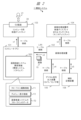
- FIG. 2 is a diagram showing the relationship between the image inspection system to be developed and the development system of the first embodiment.
- FIG. 1 is a diagram showing a first configuration example of a development system according to a first embodiment.
- FIG. 13 is a diagram showing a second configuration example of the development system according to the first embodiment.
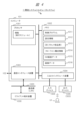
- FIG. 2 is a diagram showing an example of the configuration of the development system according to the first embodiment as a computer system.
- FIG. 2 is a diagram showing an example of the configuration of a GUI screen in the development system according to the first embodiment.
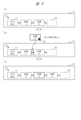
- FIG. 11 is a diagram showing an example of a block deletion operation in the first embodiment.
- FIG. 11 is a diagram showing an example of a block addition (insertion) operation in the first embodiment.
- FIG. 4 is a diagram showing an example of a block replacement operation in the first embodiment.
- FIG. 4 is a diagram showing an example of an operation related to a preview function in the first embodiment.
- 5A to 5C are diagrams showing various functions related to a preview function in the first embodiment.
- 4A to 4C are diagrams showing function 1 (preview display switching function) in the first embodiment.
- FIG. 11 is a diagram showing a target selection method for function 1 in the first embodiment.
- 13A to 13C are diagrams showing an example of displaying a moving image as detailed preview display content for function 1 in the first embodiment.
- FIGS. 11A to 11C are diagrams showing an example of a preview display using a sample input image related to function 1 in the first embodiment.
- FIG. 11 is a diagram showing an example of internal settings of a processing block relating to function 1 in the first embodiment.
- 13 is a diagram showing a preview display example of internal settings of a processing block related to function 1 in the first embodiment.
- FIG. 13 is a diagram showing an example of displaying detailed information on the internal settings of a processing block related to function 1 in the first embodiment.
- 11A and 11B are diagrams showing an example of a provisional application preview display for function 1 in the first embodiment.
- 4A to 4C are diagrams showing an example GUI of a preview display section related to function 1 in the first embodiment.
- FIG. 11 is a diagram showing an example of internal settings of a processing block relating to function 1 in the first embodiment.
- 13 is a diagram showing a preview display example of internal settings of a processing block related to function 1 in the first embodiment.
- FIG. 13 is
- FIG. 11 is a diagram showing function 2 (multiple preview function 1) in the first embodiment.
- FIG. 13 is a diagram showing a modified example of function 2 (multiple preview function 1) in the first embodiment.
- FIG. 11 is a diagram showing function 3 (multi-preview function 2) in the first embodiment.
- FIG. 4 is a diagram showing a preview mode in the first embodiment.
- FIG. 13 is a diagram showing function 4 (alert) in the first embodiment.
- FIG. 13 is a diagram showing function 5 (color information extraction) in the first embodiment.
- FIG. 13 is a diagram showing a first example of function 6 (tournament format) in the first embodiment.
- FIG. 13 is a diagram showing a second example of function 6 (tournament format) in embodiment 1.
- FIG. 13 is a diagram showing function 6 (tournament format) in the first embodiment.
- FIG. 13 is a diagram showing a modified example of function 6 in the first embodiment.
- FIG. 11 is a diagram showing the creation of multiple candidate flow lines in the first embodiment.
- FIG. 11 is a diagram showing a modified example of the display of a flow line in the first embodiment.
- FIG. 13 is a diagram showing function 7 (line sensor installation support) in the first embodiment.
- FIG. 4 is a diagram showing the internal settings of a camera capture block in the first embodiment.
- FIG. 13 is a diagram showing function 8 (template matching setting support) in the first embodiment.
- FIG. 13 is a diagram showing an example of a flow line confirmation screen in the first embodiment.
- 13A and 13B are diagrams showing a preview display/non-display switching function in the second embodiment.
- 13 is a diagram showing another example of a GUI in the preview display/non-preview switching function in the second embodiment.
- 13 is a diagram showing another example of a GUI in the preview display/non-preview switching function in the second embodiment.
- 13 is a diagram showing another example of a GUI in the preview display/non-preview switching function in the second embodiment.
- 13 is a diagram showing another example of a GUI in the preview display/non-preview switching function in the second embodiment.
- 13 is a diagram showing another example of a GUI in the preview display/non-preview switching function in the second embodiment.
- FIG. 11 is a diagram showing a preview display resolution setting function in the second embodiment.
- 13 is a diagram showing another example of a GUI in the preview display resolution setting function in the second embodiment.
- 13A to 13C are diagrams showing a preview display rotation function in the second embodiment.
- FIG. 11 is a diagram showing an example of installation of an image inspection system relating to a preview display rotation function in the second embodiment.
- FIG. 11 is a diagram showing an example of installation of an image inspection system relating to a preview display rotation function in the second embodiment.
- FIG. 13 is a diagram showing a flow line block placement availability display function in the second embodiment.
- 13 is a diagram showing another example of a GUI in the flow line block placement availability display function in the second embodiment.
- FIG. 13 is a diagram showing another example of a GUI in the flow line block placement availability display function in the second embodiment.
- FIG. 13 is a diagram showing an example of setting conditions in the flow line block placement availability display function in the second embodiment.
- FIG. 13 is a diagram showing an example of attribute settings in the flow line block placement availability display function in the second embodiment.
- FIG. 13 is a diagram showing a specific example of placement in the flow line block placement availability display function in the second embodiment.
- FIG. 13 is a diagram showing a specific example of placement in the flow line block placement availability display function in the second embodiment.
- FIG. FIG. 11 is a diagram showing a required setting/non-setting block display function in the second embodiment.
- FIG. 13 is a diagram showing a display example in the required setting/non-setting block display function in the second embodiment.
- FIG. 11 is a diagram showing a function of setting input and output images of a flow line in the second embodiment.
- FIG. 11 is a diagram showing an example of input/output video settings in the required setting/non-setting block display function in the second embodiment.
- FIG. 11 is a diagram showing an example of input/output video settings in the required setting/non-setting block display function in the second embodiment.
- FIG. 11 is a diagram showing an example of input/output video settings in the required setting/non-setting block display function in the second embodiment.
- FIG. 11 is a diagram showing an example of input/output video settings in the required setting/non-setting block display function in the second embodiment.
- FIG. 11 is a diagram showing an example of input/output video settings in the required setting/non-setting block display function in the second embodiment.
- FIG. 11 is a diagram showing a control process flow in a required setting/non-setting block display function in the second embodiment.
- FIG. 13 is a diagram showing a flow line processing block display function in the second embodiment.
- FIG. 13 is a diagram showing a detailed display example of a flow line processing block display function in the second embodiment.
- FIG. 11 is a diagram showing a display example of an internal setting field of a processing block in the second embodiment.
- the program, functions, processing units, etc. may be described as the main focus, but the main hardware focus for these is the processor, or a controller, device, computer, system, etc. that is composed of the processor.
- the computer executes processing according to the program read into the memory by the processor, appropriately using resources such as memory and communication interfaces. This realizes the specified functions, processing units, etc.
- the processor is composed of semiconductor devices such as a CPU/MPU or GPU, for example. Processing is not limited to software program processing, and can also be implemented by dedicated circuits. Dedicated circuits that can be used include FPGAs, ASICs, CPLDs, etc.
- the program may be pre-installed as data on the target computer, or may be distributed as data from a program source to the target computer.
- the program source may be a program distribution server on a communication network, or a non-transient computer-readable storage medium or non-volatile recording medium, such as a memory card or disk.
- the program may be composed of multiple modules.
- the computer system may be composed of multiple devices.
- the computer system may be composed of a client-server system, a cloud computing system, an IoT system, etc.
- the various data and information are composed of structures such as tables and lists, for example, but are not limited to these. Expressions such as identification information, identifiers, IDs, names, numbers, etc. are interchangeable.
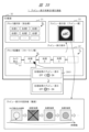
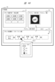
- FIG. 38 shows an example of the configuration of an image inspection system and a development system in a comparative example.
- Image inspection system 2 is the system being developed.
- Development system 3 is a computer system for developing image inspection system 2.
- Image inspection system 2 is a system that performs image inspection, such as appearance inspection, on object 20 using image processing.
- the image inspection system 2 photographs an object 20, such as a part or product moving along a factory production line, using a camera/sensor device 21, such as a line sensor or area sensor, and inputs the photographed image 50 (in other words, an image signal, etc.).
- the image inspection system 2 is a system that performs a specified image inspection process on the image 50 and outputs the results.
- the image inspection system 2 is a system that includes software, including necessary programs, hardware, data, circuits, etc.
- a line sensor (in other words, a line scan camera) is a device that, for example, has CCD image sensor elements arranged in a line, a lens, a driving circuit, etc., and can generate an image of an object by combining multiple images of a moving object captured in a line.
- An area sensor is a device that, for example, has multiple sensors arranged in a rectangular area, and can generate an image of an object corresponding to that area.
- the camera/sensor device 21 is not limited to a line sensor or area sensor, and other types of devices that can capture images can also be used.
- the specific image inspection process of the image inspection system 2 includes, for example, a camera capture process 201, an image process 202, and a judgment process 203. Each of these processes is realized by a process such as program processing by a computer or a circuit. In other words, the flow line of the image inspection system 2 is composed of a connection of process blocks or process steps corresponding to each of these processes.
- camera capture processing 201 is implemented as a first process in a first program.
- Image processing 202 is implemented as a second process in a second program.
- Determination processing 203 is implemented as a third process in a third program.
- a program is a computer program or code.
- the camera capture process 201 is a process (in other words, image input process) that inputs the image 50 (in other words, image signal) output from the camera 21 and captures it as image data, and outputs the camera-captured image 51 (also described as the first image) as a processing result.
- the image process 202 includes various processes such as binarization and image shape conversion. For example, the image process 202 inputs the camera-captured image 51, performs binarization processing, and outputs the result image 52 (also described as the second image) after the binarization processing as a processing result.
- the inspection process 203 is a process that inputs the result image 52, recognizes and detects the object 20 in the image, and judges the presence or absence, number, and appearance quality of the object 20. The inspection process 203 outputs processing result information (in other words, inspection result information, judgment result image) 53. Note that, depending on the image inspection system 2 to be developed, the inspection process 203 may not be included.
- the content of the first image 51 shows an object region 20A of the object 20 in which the letters "ABC" are written in a circle.
- the first image 51 is, for example, a full-color image, but is shown in black and white as a schematic in the drawing.
- the content of the second image 52 shows a binarized object region 20B.
- the image inspection system 2 is configured by connecting multiple processing blocks, such as camera capture processing 201, image processing 202, and inspection processing 203, and can also be expressed as a processing flow diagram such as that shown in Figure 38. Such a configuration of the image inspection system 2 may be referred to as a flow line.
- an image inspection system 2 may be configured using a model based on machine learning (e.g., deep learning), or may be configured using general image processing technology without using a model based on machine learning.
- a model based on machine learning may be applied to any processing block (in other words, processing step) on the flow line of the image inspection system 2.
- a CNN convolutional neural network
- the processing block outputs an estimation result based on CNN for an input image.
- the development system of the embodiment is applicable.
- the development system 3 is a computer system that includes a development environment for developing and creating such an image inspection system 2.
- a user such as an engineer performs development work for this image inspection system 2 using a computer system in which development software and the like are installed.
- the computer system can be configured using general PCs, servers, databases, communication interfaces, input devices, output devices, and the like.
- the engineer performs work to develop and create, by programming, a first program for the camera capture process 201, a second program for the image processing 202, a third program for the judgment process 203, and the like.
- the user first completes the flow line of the image inspection system 2 up to the end (e.g., inspection process 203) and then checks the overall operation of the image inspection system 2. After checking, the user changes part of the flow line in response to design changes, debugging, etc. After that, the user checks the overall operation of the image inspection system 2 again. Even if the conventional development system 3 has a preview function for checking operation, the only thing that can be previewed is the processing result of the entire flow line of the image inspection system 2 for the input image 50. Therefore, this type of development work requires a lot of work from the user.
- the development system according to the embodiment has the following solutions.
- the development system of the embodiment is a computer system that constitutes an environment for developing and creating software for the image inspection system 2.
- the development system of the embodiment is a system that constitutes a GUI-based development environment that includes a graphical user interface (GUI) for developing and creating the image inspection system 2.
- GUI graphical user interface
- the development system 1 of the first embodiment shown in FIG. 1 etc. is a computer system including an application program etc. that supports the development and creation of a flow line corresponding to the image inspection system 2.
- This development system 1 generates a GUI-based screen (sometimes referred to as a GUI screen) having a unique graphical user interface (GUI) and display content not found in conventional technology, and provides it to the user U1.
- GUI graphical user interface
- This GUI screen is displayed on the screen of any display device.
- This GUI screen may be provided in the form of, for example, a web page or the like.
- User U1 such as an engineer who performs development work using development system 1, uses the functions of development system 1 by operating the GUI screen while looking at the GUI screen. User U1 uses the GUI to develop and create programs for each process (e.g., camera capture process 201, image process 202, and judgment process 203) that make up the flow line of image inspection system 2.
- process e.g., camera capture process 201, image process 202, and judgment process 203
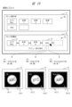
- FIG. 1 shows an example of the configuration of an image inspection system 2, which is a system to be developed, and a development system 1 of the first embodiment.
- the image inspection system 2 has a configuration similar to that of the comparative example of FIG. 38.
- the image inspection system 2 photographs an object 20 by a camera/sensor device 20 such as a line sensor or an area sensor, and inputs the photographed image 50.
- the image inspection system 2 performs, for example, a camera capture process 201 on the input image 50, and obtains a camera-captured image (first image) 51 as a processing result.
- the image inspection system 2 performs, for example, image processing 202 such as binarization on the camera-captured image 50, and obtains a result image (second image) 52 as a processing result.
- image inspection system 2 performs an inspection process 203 such as a judgment process on the result image 52, and obtains inspection result information, in other words, judgment result information 53.
- Development system 1 is a system that supports the work of developing and creating a flow line corresponding to image inspection system 1, for example a flow line consisting of a connection of processing blocks such as camera capture processing 201, image processing 202, and inspection processing 203.
- Development system 1 is a system that supports the work of developing software for image inspection system 1, for example processing programs such as a first program that constitutes camera capture processing 201, a second program that constitutes image processing 202, and a third program that constitutes inspection processing 203.
- Development system 1 supports these development tasks based on GUI operations on a GUI screen by user U1.
- the development system 1 has at least a flow line editing function F1 and a preview display function F2.
- the flow line editing function F1 allows the user to create and edit flow lines by connecting process blocks prepared in advance as components on the GUI screen using methods such as drag and drop.
- this GUI screen can display a preview screen using the preview display function F2 in relation to the flowline created by the flowline editing function F1.
- the preview display function F2 is a function that controls the preview display of the flowline on the preview screen.
- the preview display function F2 targets flowlines or processing blocks, etc. that are in the process of being created by the flowline editing function F1, and realizes a preview display of their operating status and processing results.
- the preview screen can display a preview image that shows the operating status of a provisional flowline that is in the process of being created.
- FIG. 2 and 3 show implementation configuration examples of the development system 1 of the embodiment 1.
- Fig. 2 shows a first implementation example
- Fig. 3 shows a second implementation example.
- the first implementation example of Fig. 2 will be described as the basis, but the second implementation example of Fig. 3 is also possible as a modified example.
- the development system 1 of the first embodiment is a system mainly configured by connecting a computer 101 and an image processing device 102.
- the computer 101 can be configured, for example, as a single general PC.
- the computer 101 has a general OS, middleware (file system, web server, etc.), a communication interface, etc., and has an image inspection system development environment 500 as software.
- This image inspection system development environment 500 corresponds to the software of the development system 1 (including computer programs, databases, etc.).
- the computer 101 and the image processing device 102 are connected by a LAN, for example via a cable connection, and each has a communication interface compatible with the LAN.
- the implementation of the development system 1 is not limited to a single PC configuration, but may also be a client-server system (e.g., a Web system).
- a computer video display 103 is externally connected to the computer 101 via a cable as a display device.
- the computer 101 transmits a video signal s1 to the computer video display 103, thereby displaying the GUI screen 30 generated by the development environment 500 on the screen of the computer video display 103.
- an input device such as a mouse is externally connected to the computer 101.
- the computer image display 103 may be a touch panel.
- the image processing device 102 is a part that functions as an image input engine for the software (development environment 500) of the development system 1.
- the digital signal output device 105 is connected to the image processing device 102 via a cable.
- the digital signal output device 105 is, for example, a camera or a sensor device.
- the digital signal output device 105 which is a camera, has a shooting function and functions as a part corresponding to the camera/sensor device 21 in FIG. 1.
- the digital signal output device 105 which is a camera, transmits an image signal s4 of the captured image to the image processing device 102.
- the image processing device 102 generates an image 15 (image data) based on the image signal s4 and transmits it to the computer 101 as a signal s3.
- the computer 101 receives the image 15 and sets it as the image to be processed in the development environment 500.
- the image processing device 102 is connected to an auxiliary storage device 106 (e.g., a USB memory) via a cable connection.
- the image processing device 102 can read and write data and information (signal s6) such as images from and to the auxiliary storage device 106.
- the image processing device 102 is connected to a monitor display 104 via a cable connection.
- the monitor display 104 is a video display for the image processing device or a touch panel.
- the image processing device 102 transmits a video signal s2 corresponding to an image captured by the digital signal output device 105 to the monitor display 104.
- the monitor display 104 displays an image on a screen based on the video signal s2. If the monitor display 104 or the computer video display 103 is a touch panel, the user can input instructions to the computer 101 or the image processing device 102 by touching the screen of the touch panel.
- the development environment 500 of the computer 101 implements the flow line editing function F1 and preview display function F2 of FIG. 1, and holds data FD of the flow lines of the image inspection system 2 to be created.
- the development system 1 of the first embodiment is mainly composed of one stand-alone image processing device 102 (102B), which is configured as, for example, a video camera device.
- the image inspection system development environment 500 of the computer 101 in FIG. 2 is integrated and implemented in this image processing device 102 (102B).
- the computer 101 in FIG. 2 and the like can be omitted.
- the auxiliary storage device 107 may be connected to the image processing device 102B via a cable-connected LAN.
- the image processing device 102B may transmit data such as the captured image 15 to the auxiliary storage device 107 as a signal s3 and store the data in the auxiliary storage device 107.
- FIG. 4 shows an example of the configuration of the development system 1 (e.g., Fig. 2) as a computer system 1.
- Fig. 4 shows a case having a computer 101, an input device 1005 and an output device 1006 externally connected to the computer 101, and a client terminal device 1030 connected via a communication network 1020 (e.g., a LAN).
- the client terminal device 1030 is used in the case of a client-server system configuration, but is not essential.
- the computer 101 comprises a processor 1001, a memory 1002, a communication interface device 1003, an input/output interface device 1004, etc., and these components are interconnected via a bus.
- An input device 1005 and an output device 1006 are externally connected to the input/output interface device 1004.
- the computer 101 may also have the input device 1005 built in. Examples of the input device 1005 include a mouse, keyboard, and microphone. Examples of the output device 1006 include a display, printer, and speaker.
- the communication interface device 1003 is equipped with a communication interface with the image processing device 102 in Figure 2 and a communication interface with the LAN 1020.
- the processor 1001 executes processing according to the program read into the memory 1002. This allows a given function (such as the flow line editing function F1 described above) to be realized as an execution module.
- the memory 1002 stores a control program 1011, setting information 1012, DB 1013, flow line configuration information 1014, GUI screen data 1015, image data 1016, etc.
- the memory 1002 can be configured with a non-volatile storage device, but is not limited to this.
- a memory resource e.g., a DB server
- external to the computer 101 may also be used.
- DB1013 as a database that constitutes the software of development environment 500 in FIG. 2, contains data and information such as processing blocks that are components for constructing flowlines.
- the processing blocks that constitute flowlines are, in substance, program modules and related data and information (including, for example, files, tables, lists, etc.).
- Flowline configuration information 1014 is configuration information of the flowline of image inspection system 2, and corresponds to the flowline data FD in FIG. 2.
- Flowline configuration information 1014 corresponds to flowline data created and saved by the user.
- Flowline configuration information 1014 represents the configuration and setting state of processing blocks, etc. in the flowline.
- Development system 1 can reproduce the flowline by reading out flowline configuration information 1014.
- the GUI screen data 1015 is data for providing the aforementioned GUI screen 30 to the user, and includes GUI component data for constructing a specific GUI, and data such as images to be displayed within the GUI screen 30.
- the image data 1016 is image data obtained from the camera 21 in FIG. 1, the image processing device 102 and the digital signal output device 105 in FIG. 2, or image data generated as a processing process or processing result during the creation of a flow line in the development environment 500.
- the image data 1016 may be data such as an image file that includes attribute information for each image.
- data and information generated during the processing in the development system 1 is appropriately stored in memory resources such as memory 1002.
- memory resources such as memory 1002.
- Each piece of data and information may be stored in an auxiliary storage device such as that shown in FIG. 2, etc.
- User U1 may also use the client terminal device 1030 to remotely access the computer system 1 as a server and use the functions of the development system 1.
- the development system 1 is in the form of a client-server system
- the following operation is performed, for example.
- the user operates the client terminal device 1030, which accesses the computer 101 of the development system 1 and sends a request.
- the computer 101 sends a response to the client terminal device 1030 using a web page or the like.
- the client terminal device 1030 receives the response and displays the above-mentioned GUI screen 30 or the like on its display.
- the user looks at the GUI screen 30 and inputs instructions, settings, etc. as appropriate.
- the client terminal device 1030 sends information such as the instructions to the computer 101.
- the computer 101 executes processing using the functions of the development environment 500 in response to the instructions, etc., and stores the processing results (for example, a flow line or a preview image).
- the computer 101 sends processing result information, etc. to the client terminal device 1030.
- the client terminal device 1030 displays a GUI screen 30 on which processing result information and the like are displayed. The user can view and confirm the processing result information and the like on the GUI screen 30.
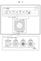
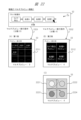
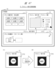
- FIG. 5 shows an example of a GUI screen 30 as a simplified configuration of a GUI in the development environment 500 of the development system 1.
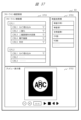
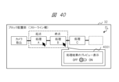
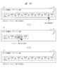
- the GUI screen 30 in Fig. 5 has a block selection section 31 (in other words, a parts column), a block placement section 32 (in other words, a flow line column), and a preview display section 33 (in other words, a preview column).
- the GUI screen 30 also has general GUI components such as a menu, a scroll bar, and command buttons.
- User U1 operates an input device such as a mouse or keyboard to operate cursor 39 and the like on GUI screen 30.
- User U1 selects a desired processing block BL from a plurality of processing blocks BL provided as components in block selection section 31, and moves and places the processing block BL in block placement section 32, for example by drag and drop. In this way, user U1 creates a desired flow line FL by connecting processing blocks BL together in block placement section 32.
- the block selection section 31 contains processing blocks BL such as a "camera capture” block b1, a "judgment” block b2, a “processing A” block, a “processing B” block, and a “processing C” block.
- processing blocks BL such as a "camera capture” block b1, a "judgment” block b2, a “processing A” block, a “processing B” block, and a “processing C” block.
- "Processing A” and the like are, for example, various types of image processing, and are symbolized and illustrated in schematic form.
- This example shows a case where user U1 selects the "processing C" block in the block selection section 31 with cursor 39, and then uses drag and drop to place it next to (in other words, behind, to the right of) the "processing B" block in the block placement section 32 so that it is connected to it.
- the flow line FL is configured and displayed, for example, in such a manner that the processing blocks BL are connected by lines.
- a provisional flow line FL in the process of being created which is placed in the block placement section 32, is arranged from the left as processing blocks BL, with a "camera capture” block b1, a "processing A” block, a “processing B” block, and a “processing C” block.
- the provisionally last block is the "processing C" block, and no blocks are placed after the "processing C" block.
- Such a state in which the next block has not been placed is displayed as a blank block BS indicated by a dashed frame.
- user U1 wants to connect the next block to the flow line FL, he or she simply places the next block in the position of the blank block BS.
- a blank block BS may not be provided, and when the next processing block BL is moved into the block placement section 32, the processing block BL may be connected to the end of the flow line FL.
- the flow line editing function F1 which will be described in detail later, allows the user U1 to use the processing blocks BL in the block selection unit 31 to add, delete, replace, etc. the processing blocks BL in the block placement unit 32, thereby creating a flow line FL with the desired configuration.
- User U1 can also use the preview display function F2 to display a preview of the operating state of a provisional flow line FL under creation that is placed and displayed in the block placement unit 32 in the preview display unit 33.
- the user performs a predetermined preview execution operation on the flow line FL in the block placement unit 32.
- the development system 1 displays a preview image of the operating state of the flow line FL in the preview display unit 33.
- the previewed operating state of the flow line FL is the operating state of the target or range specified by the operation of user U1.
- the target or range is at least one processing block of the flow line FL, and will be described in detail below.
- the flow line FL is arranged and displayed from left to right, but of course this is not limited to this and may be arranged from top to bottom, for example.
- the block selection section 31, block arrangement section 32, and preview display section 33 are arranged from top to bottom in this order within the GUI screen 30, but this is not limited to this.
- Each column can be arranged in the GUI screen 30 at a position and size that is easy for user U1 to operate.
- Each column may be an independent window, or may be displayed in response to an operation, etc., rather than being constantly displayed.
- the block selection unit 31 may also organize and arrange the multiple processing blocks BL by category, type, hierarchy, etc.
- categories and types are “input/output” and “image processing.”
- hierarchies include “binarization,” “image shape conversion,” “filtering,” “feature extraction,” “arithmetic operations,” “logical operations,” “rotation,” “enlargement/reduction,” “graphics drawing,” “pattern matching/template matching,” “dimension measurement,” and “object detection” as subcategories under the “image processing” category. Further hierarchies may also be provided under the subcategories.
- the various processing blocks BL may be provided with different aspects such as color or shape to make them easier to identify.
- the block selection unit 31 may be provided with a search field to enable searching of the processing blocks BL.
- the block selection unit 31 may be provided with an input image block as a component.
- the input image block is a block that specifies the image to be input to the processing block BL, such as the "camera capture" block b1, for example.
- development system 1 saves the configuration of the flow line FL at that time in block placement unit 32 in memory resources, for example as data such as a file (flow line data FD in FIG. 2, flow line configuration information 1014 in FIG. 4).
- the GUI screen 30 also provides a GUI (such as a general file selection dialog) for selecting the flow line FL to be edited from the data of saved flow lines FL.
- a GUI such as a general file selection dialog
- a dedicated flow line confirmation screen is provided.
- the user U1 selects the flow line FL to be edited from the data of saved flow lines FL.
- the development system 1 reproduces the selected flow line FL by placing it in the block placement section 32. This allows the user U1 to edit that flow line FL again.
- the GUI screen 30 may also provide a way to create and edit multiple flow lines FL, as described below.
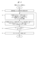
- [Development system process flow] 6 shows a main processing flow of the development system 1, which has steps S1 to S5.
- the development system 1 displays a GUI screen 30 (e.g., FIG. 5) based on an operation by the user U1.
- the GUI screen 30 allows the user U1 to make settings, select a mode to be described later, select a file to be processed, and so on.
- step S2 the development system 1 selects a processing block BL from the block selection unit 31 based on the operation of the user U1 on the GUI screen 30, and creates and edits the flow line FL by placing the selected processing block BL in the block placement unit 32.
- the development system 1 updates and stores the configuration state of the flow line FL according to the operation as data.
- step S3 the development system 1 displays a preview of the operating state of the provisional flow line FL (particularly the specified target/range) being created in the preview display section 33 based on the operations of the user U1 on the GUI screen 30, particularly the preview execution operation.
- step S4 user U1 checks whether the flow line FL is complete, whether any changes are required, etc., and confirms whether to save the completed flow line FL and exit, or to save the flow line FL that is being created and exit. If saving is selected in step S4 (Y), then in step S5, development system 1 saves the current configuration state of the flow line FL as data such as a file, and terminates the application of development system 1. If not saving is selected in step S4 (N), the process returns to step S2, and user U1 repeats the development work in the same manner.
- step S4 user U1 performs a specified save operation on GUI screen 30 (e.g., inputting a command to save the flow line), and development system 1 displays a confirmation message such as "Do you want to save the flow line being edited?" and user U1 presses the "OK (save)" button, causing development system 1 to save the flow line FL at that time as data. Note that it is also possible to automatically save the flow line FL data at a specified timing according to user settings.
- the development system 1 of the first embodiment has a flow line editing function F1 as a first method.
- the flow line editing function F1 is a function that allows a user U1 to freely edit and create a flow line FL of the image inspection system 2 by connecting processing blocks BL prepared in advance in a block selection unit 31 on a GUI screen 30 (FIG. 5) by a GUI operation (e.g., drag and drop, etc.) and arranging the processing blocks BL in a block arrangement unit 32.
- Fig. 7 to Fig. 10 show detailed operations and examples of GUIs when creating and editing a flow line FL as in Fig. 5.
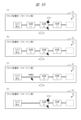
- Fig. 7 shows the flow of sequentially placing process blocks BL in the block placement unit 32 when creating a flow line FL.
- FIG. 7 shows the initial state of the block placement section 32 in which no processing blocks BL have been placed.
- a blank block BS may be displayed in the block placement section 32 at this time.
- the blank block BS serves as a guide for placing the first or next processing block BL, and is illustrated, for example, as a rectangle with a dashed line frame.
- the GUI may be such that a processing block BL can be added to the flow line FL only when the processing block BL is placed at the position of the blank block BS.
- the GUI may be such that a processing block BL can be added to the flow line FL when the processing block BL is placed at a position other than an existing processing block BL in the block placement section 31.
- the user U1 places a processing block BL selected from the block selection unit 31, for example, a "camera capture” block b1, in the position of a blank block BS in the block placement unit 32. This places the "camera capture” block b1 as the first block on the flow line FL.
- FIG. (B) shows the state in which the "camera capture” block b1 has been placed.
- the blank block BS is displayed by moving it behind the placed "camera capture” block b1.
- the user U1 places the next processing block BL selected from the block selection section 31, for example the "processing A" block, in the position of the blank block BS, for example, in the block placement section 32.
- (C) shows the state in which the "Processing A” block has been placed behind the "Camera capture” block b1.
- the blank block BS is moved and displayed behind the placed "Processing A” block.
- the user U1 places the next processing block BL, for example the "Processing B” block, selected from the block selection section 31 in the position of the blank block BS, for example, in the block placement section 32.
- (D) shows the state in which the "Process B” block has been placed behind the "Process A” block.
- the blank block BS is moved and displayed behind the placed "Process B” block.
- User U1 places the next process block BL, for example the "Process C” block, selected from the block selection section 31 in the position of, for example, the blank block BS in the block placement section 32.
- a flow line FL like that shown in Figure 5 can be created.
- the operation of adding blocks is not limited to the above example.
- user U1 selects a desired processing block BL in the block selection unit 31, and inputs a block addition command by, for example, right-clicking on that block.
- the development system 1 places the processing block BL so that it is added to the end of the flow line FL in the block placement unit 32.
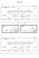
- [Creating and editing flow lines (2)] 8 shows an example of the operation when deleting a process block BL from a flow line FL.
- a user U1 wants to delete a desired process block BL from a flow line FL
- the user U1 selects the process block BL to be deleted and performs a predetermined deletion operation.
- the development system 1 deletes the process block BL from the flow line FL in the block placement unit 32.
- the predetermined deletion operation may be, for example, a deletion command input as shown in the figure. For example, candidate commands are displayed in response to a right click, and the delete command is specified from the candidate commands.
- Another example of the predetermined deletion operation may be an operation of dragging and dropping the processing block BL selected by the user U1 out of the block arrangement section 32. For example, it may be an operation of returning it to the block selection section 31, or an operation of placing it in a predetermined trash can field.
- (C) shows the state of the flow line FL after the deletion operation in (B). In this state, the "Process A” block before the deleted “Process B” block and the “Process C” block after the deleted “Process B” block are connected by a line.
- the development system 1 also allows for an Undo operation by storing a history of operations performed by the user U1 on the flow line FL in the block placement unit 32. For example, if the user U1 wishes to undo the deletion of a block from (B) to (C), the user U1 performs a specific Undo operation (e.g., inputting an Undo command). This makes it possible to revert from the (C) state to the (B) state.
- a specific Undo operation e.g., inputting an Undo command
- FIG. 9 also shows a variation of the block addition operation, in which user U1 inserts a process block BL into the middle of a flow line FL.
- the flow line FL has a "camera capture” block b1, a "process A” block, and a “process B” block arranged thereon.
- user U1 wants to insert "process D” between “process A” and “process B", for example, he or she selects the "process D” block from the block selection unit 31 as shown in (B), and places it near the line between the "process A” and “process B” blocks in the block placement unit 32 by dragging and dropping it.
- the development system 1 adds the "process D” block between the "process A” and “process B” blocks in the flow line FL as shown in (C), connecting them with a line.
- development system 1 may display possible locations on the flow line FL of block placement unit 32 where that processing block BL can be placed in a predetermined manner for easy understanding. For example, if the "Process D" block is selected in (B), possible locations where that "Process D" block can be placed include not only the blank block BS after the "Process B” block, but also the line between the "Process A” block and the "Process B” block. In that case, development system 1 displays these possible locations as areas of a predetermined color, or in other manner. The possible locations may also include block replacement locations, which will be described later.
- FIG. 10 shows an example of an operation when a process block BL in a flow line FL is replaced with another process block BL.
- (A) of FIG. 10 in the block arrangement section 32, up to the "Process C" block is arranged as an example of a flow line FL in a state before replacement. From this state, assume that the user U1 wants to replace the "Process A" block with the "Process D" block. The user U1 selects the "Process D" block to be replaced from the block selection section 31, and places it in the position of the "Process A" block to be replaced (in other words, before replacement) in the block arrangement section 32 by dragging and dropping.
- the development system 1 replaces the "Process A” block with the "Process D” block as shown in (B).
- the development system 1 may display the portion of the process block BL that can be replaced in a predetermined color or other manner according to the process block BL selected by the user U1.
- the development system 1 of the first embodiment has a preview display function F2 as the second method.
- the preview display function F2 is a function that displays a preview of the operation state of the flow line FL created and edited by the flow line editing function F1 of the first method on the preview display unit 33.
- This preview display function F2 displays a preview image that represents the operation state of a specified target/range (e.g., the range up to a specified processing block) in the provisional flow line FL of the block arrangement unit 32.
- the preview image is, for example, a processing result image for each point (i.e., output value) after each block in the range from the first processing block of the flow line FL to the specified processing block.
- the preview display function F2 allows user U1 to preview the operation status of the provisional flow line FL at any time, making it easier to check the operation of the flow line FL and debug it.
- the preview display function F1 has various types of preview display functions, which will be described later, that can assist user U1 in their development work.
- development system 1 displays a preview image of the provisional operating state of flow line FL at that time in preview display section 33.
- the preview display target/scope at that time can be defined in various ways, but one example is all blocks from the beginning to the end of the flow line FL at that time.
- the preview image displayed on preview display section 33 is a moving image or animation that continuously displays the processing result images of each block in chronological order.
- the preview display target/range when user U1 specifies a desired processing block BL in the block placement unit 32 and performs a preview execution operation, the preview display target/range will be, for example, the range from the beginning of the flow line at that time to the specified processing block.
- the preview display target/range when user U1 specifies a desired processing block BL in the block placement unit 32 and performs a preview execution operation, the preview display target/range will be, for example, only the specified processing block.
- the specified preview execution operation can be defined in various ways, but examples include the following.
- One example of a preview execution operation is a specific operation such as double-clicking on a blank space or a desired processing block in the block placement section 32.
- Another example of a preview execution operation is inputting a preview display command.
- user U1 can select and input a preview display command from candidate commands by right-clicking, etc.
- Another example may be pressing the preview display button in the GUI screen 30.
- Another example of a preview execution operation may be an operation such as double-clicking on an area of the preview display section 33.
- Another example may be user U1 selecting a desired block in the block placement section 32 and arranging it in the preview display section 33 by dragging and dropping.
- the development system 1 may determine the target/range of the preview to be the entire provisional flow line FL (from the beginning to the end). Also, if a specific processing block BL is specified/selected as a preview execution operation, the development system 1 may determine the target/range of the preview to be the target/range of the provisional flow line FL that includes the specified processing block (for example, the range from the beginning to the specified block).
- GUIs, operations, and preview display targets/ranges are implemented in advance in the software of the development system 1 and can be specified according to each function. They may also be selectable/switchable according to the mode or user settings described below.
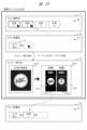
- [Preview display (1)] 11 shows an example of operation related to the preview display function F1.
- (A) shows a first example of preview display
- (B) shows a second example.
- the block arrangement section 32 has a provisional flow line FL arranged from the "camera capture” block b1 to the "process C" block.
- the user U1 selects a desired process block BL, for example, the "camera capture” block b1 (or the line portion immediately following the block) in the flow line FL at that time, and performs a predetermined preview execution operation.
- the development system 1 displays a preview of an image of the process result from the beginning of the flow line FL at that time to the selected process block BL in the preview display section 33.
- the range is only the "camera capture” block b1
- the image of the process result that is the output of the "camera capture” block b1 is the target.
- the development system 1 displays the image of the process result that is the output of the "camera capture” block b1 (corresponding to the camera capture image 51 in FIG. 1) in the area of the preview display section 33 as a preview image 1101.
- development system 1 sets the preview target/range to images of the processing results of each block in the range from the first "Camera Capture” block b1 in flow line FL to the selected "Processing A” block.
- Development system 1 displays the processing result image of "Camera Capture” block b1 and the processing result image of the "Processing A” block (videos of these) as preview images 1102 in the area of preview display section 33.
- the processing result image of the "Processing A” block is the image that results from inputting the camera-captured image, which is the output of the "Camera Capture” block b1, into the "Processing A” block and processing it.
- the "Processing A” block is a binarized image process
- the result will be the binarized image (corresponding to the result image 52 in Figure 1).
- user U1 can select a desired processing block BL on the flow line FL and perform a preview execution operation to display a preview of the processing results up to the selected block.
- the preview target/range is from the first block of the flow line FL to the specified block.
- the processed result image of each block becomes the preview display target, and the preview display unit 33 previews multiple processed result images as videos, animations, etc. in chronological order (see FIG. 15 below).
- the target/scope of the preview can be limited to only one processing block selected/specified by the user U1.
- the input and output of the "camera capture” block b1 will be supplemented.
- the development system 1 has images and videos captured and input in real time by the camera/sensor device 21 (FIG. 1) of the image inspection system 2 or the camera/sensor device (digital signal output device 105 in FIG. 2) of the development system 1. This corresponds to the image 50 input to the camera capture process 201 in FIG. 1 and the image 15 in FIG. 2.
- Such an image 50 is an image (sometimes referred to as an input image or an image to be processed) input to the "camera capture” block b1 on the flow line FL in FIG. 5.
- the "camera capture” block b1 is an "image input” block.
- the "camera capture” block b1 outputs an image (camera capture image 51 in FIG. 1) resulting from a predetermined camera capture process performed on this input image.
- This camera capture process is, for example, a process of sampling the signal of the image 50 corresponding to the camera/sensor device 21 at a predetermined capture period or the like (internal setting described later) and converting it into image data having pixel values.
- the input image to the "camera capture” block b1 is not limited to footage captured in real time by an actual camera, but can also be other types of images. Examples of other types of images include image data that is arbitrarily created, set, or specified in advance by the business operator or user U1.
- Fig. 12 summarizes examples of various detailed preview display functions related to the preview display function F2 provided in the development system 1 of the first embodiment.
- the development system 1 may display various functions such as those shown in Fig. 12 in a GUI such as a menu on the GUI screen 30, and allow the user U1 to select and execute or set the functions. It is of course possible to implement only one of these functions, or to implement a predetermined number of functions, without being limited to the example of Fig. 12.
- the development system 1 switches, for example, the preview display function selected by the user U1 on the GUI screen 30 so that it is in an active state.
- the development system 1 prepares a control mode, for example, for each preview display function.
- the development system 1 switches the control mode to a mode in which that function can be used.
- the GUI on the GUI screen 30 is also switched according to that mode.
- the GUI for each mode includes a system for interpreting what command or process is assumed when a specific operation (e.g., single click, double click, etc.) is performed on an object to be operated, such as a processing block or preview column.
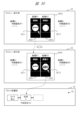
- [Function 1: Preview display switching function] 13 is an explanatory diagram of a preview display switching function by block selection as function 1.
- Function 1 is a function that can select a preview display target in response to an operation by user U1, and can switch the preview display content in response to, for example, the selection of a processing block BL.
- Function 1 may be a normal preview function that is the basis of embodiment 1.
- the development system 1 may control the state in which function 1 is enabled as a predetermined mode (mode 1) in terms of control.
- a "camera capture” block b1 a "processing A” block, a “processing B” block, and a “processing C” block are arranged in that order as a provisional flow line FL in the block arrangement section 32.
- user U1 previews the flow line FL based on a predetermined preview execution operation (e.g. double-clicking a processing block BL, or inputting a preview display command).
- a predetermined preview execution operation e.g. double-clicking a processing block BL, or inputting a preview display command.
- function 1 includes the following function 1a, etc.
- development system 1 targets the process block BL located at the end of the flow line FL at that time, for example, the "Process C" block, as the preview target.
- Development system 1 displays the processing result image of the target "Process C" block as preview image 1301 in preview display unit 33.
- the preview target is a single process block, and the preview image is a still image.
- FIG. 13 illustrates this case as Example 1.
- the development system 1 may automatically display a preview of the last processing block BL of the current flow line FL in the preview display unit 33.
- the preview target is a single processing block as described above
- the processing result image that is the output of that processing block but also the image that is the input of that processing block may be displayed in the area of the preview display section 33.
- the input image and the processing result image may be displayed in parallel in the area of the preview display section 33, or the images may be displayed while switching between them in chronological order.
- the target/range of the preview display may be from the beginning of the flow line FL to a specified processing block, and the preview image may be a video of the processing result images of each block.
- the target and range of the preview display such as whether it is an image of the output of only one processing block BL specified by user U1, as in the above example, an image of input and output, or from the beginning of the flow line FL to the specified block, is determined by the software implementation of development system 1, and user U1 can use it according to the function and GUI operation.
- function 1b user U1 can select another desired processing block BL in the flow line FL (for example, the "camera capture” block b1 or the "processing B" block) and preview that processing block.
- This function 1b allows user U1 to check the processing contents of the desired processing block BL in the flow line FL.
- the preview target can be specified in various ways for function 1b as well.
- (Function 1c) In addition to functions 1a and 1b, it has function 1c.
- user U1 performs another predetermined operation (for example, a second click, double click, or another command input) on, for example, the "Process A" block selected in function 1b.
- the development system 1 switches the internal setting (described in detail later) for the "Process A” block, and displays a preview of the processing result image of the "Process A" block with the switched internal setting. For example, assume that the internal setting of the "Process A" block is initially the first internal setting.
- (Function 1d) It also has functions 1d and 1e.
- the user U1 operates, for example, the "Process A" block as a component in the block selection unit 31 by clicking or the like.
- the development system 1 previews the selected and designated “Process A” block alone, and switches the preview display content in the preview display unit 33 to the processing result image of the selected "Process A” block (described later).
- the development system 1 uses a sample input image that has been set in advance as the input image.
- the development system 1 inputs the sample input image into the "Process A" block, obtains a processing result image, and displays it as a preview image.
- the user U1 can check the processing content of each processing block BL, which is a component that constitutes the flow line FL, in a preview.
- function 1 allows user U1 to easily determine and confirm which processing block BL should be placed next on the flow line FL of block placement unit 32 by appropriately using the preview display. Even if user U1 does not understand the detailed processing content of the processing block (e.g., program code), he or she can visually confirm it from the preview display result, making it easy to create the flow line FL.
- the processing block e.g., program code
- [How to select blocks to preview] 14 shows, as a supplement to Fig. 13, several types of methods relating to GUI operations and the like for selecting and specifying one or more processing blocks BL that are to be the target and range of the preview display. At least one of these methods is implemented as a function of the development system 1.
- FIG. 1 shows the first method, in which the preview target is only one processing block BL selected by user U1.
- the processing block BL to be previewed is shown surrounded by a dashed frame.
- User U1 selects the desired processing block BL, for example the "Process B" block, from the flow line FL of the block placement section 32 with the cursor or the like, and performs a specified preview execution operation. This displays a preview of the specified processing block BL.
- FIG. (B) shows the second method, in which the preview target is the range from the first processing block BL of the flow line FL to one processing block BL (also referred to as the end block) selected by the user U1.
- the user U1 selects a desired end block, for example the "processing B" block, from the flow line FL in the block placement unit 32 with the cursor or the like, and performs a specified preview execution operation. This causes a preview to be displayed of each processing result image of multiple blocks in the range from the first block of the flow line FL to the specified end block.
- FIG. (C) shows a third method, in which the preview target is the range from one processing block BL (also referred to as a starting block) selected by user U1 of the flow line FL to the last processing block BL of the flow line FL.
- User U1 selects a desired starting block (e.g., a "processing B" block) from the flow line FL in block placement unit 32 with a cursor or the like, and performs a specified preview execution operation. This causes a preview display of each processing result image of multiple blocks in the range from the specified starting block to the last block of the flow line FL.
- a desired starting block e.g., a "processing B" block
- (D) shows a fourth method, in which the preview target is the range from the first block (starting block) of the flow line FL selected by the user U1 to the second block (ending block) selected by the user U1.
- the user U1 selects the desired first block, for example the "Process A” block, from the flow line FL in the block arrangement unit 32, then selects the desired second block, for example the "Process B" block, and performs a predetermined preview execution operation. This causes a preview to be displayed of each processing result image of multiple blocks in the range from the first block to the second block of the flow line FL.
- FIG. 15, as a supplement to FIG. 13, shows a case where the process result images of each of the target processing blocks BL are displayed in sequence in the preview display section 33 like a moving image/animation.
- the "processing C" block is selected in the block arrangement section 32, and a preview execution operation is performed.
- the development system 1 sets the target/range of the preview display to the range of four processing blocks BL from the "camera capture” block b1 to the "processing C" block.
- the development system 1 displays the process result images of each of these four processing blocks BL in the area of the preview display section 33, for example, as a loop while switching them sequentially on the time axis.
- the preview image 1500 displayed in the preview display section 33 is displayed while switching in sequence, such as a camera capture result image 1501, a processing A result image 1502, a processing B result image 1503, a processing C result image 1504, and a camera capture result image 1501, and is displayed like a moving image/animation by changing, for example, four still images.
- the preview target/range is a video that spans multiple processing blocks
- user U1 can specify a desired point in the video and display the preview as a still image.
- FIG. 16 is an explanatory diagram of a preview display function of a processing block BL using a sample input image of the above function 1d, as a supplement to Fig. 13.
- a user U1 can select a desired processing block BL in the block selection unit 31 separately from the current flow line FL in the block arrangement unit 32 and perform a predetermined preview execution operation to preview (herein also referred to as a sample preview) the selected one processing block BL.
- user U1 selects the target "Processing C" block in block selection unit 31, and performs a preview execution operation in the sample image method (e.g., inputting a sample preview command).
- development system 1 applies a preset sample image (sample input image) as an input image to the selected "Processing C” block.
- Development system 1 obtains the processing result image of the "Processing C” block for that sample input image as a sample processing result image.
- development system 1 displays sample input image 1601 and sample processing result image 1602 as preview images in the area of preview display unit 33. This allows user U1 to check the function and effect of the selected processing block BL in a preview.
- the sample input image is associated with the processing block BL and is set and saved in advance in the DB of the development system 1.
- the user U1 may be able to select and specify the sample input image to be input to the processing block BL.
- a general file reading GUI may be applied as the GUI.
- the block selection unit 31 may be used, as shown in the lower part of Figure 16.
- a number of set sample images are arranged in the form of blocks. For example, a category of sample images may be managed as one of the tabs.
- the user U1 can select the desired sample image block from within the block selection unit 31 and apply it.
- sample input image 1601 in preview display section 33 may be omitted.
- a sample processing result image using a sample input image, such as sample preview image 1602 may be associated and saved in advance. In this way, when performing a sample preview, the processing of processing block BL may be omitted, and the saved sample preview image may be read out and displayed as a preview.
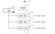
- FIG. 17 is a diagram for explaining the internal settings for each processing block BL as a supplement to FIG. 13.
- the processing block BL which is a component
- the internal settings 1710 have internal settings 1711, 1712, and 1713.
- the internal setting 1711 is "normal binarization”
- the internal setting 1712 is “range binarization”
- the internal setting 1713 is "Otsu's binarization”.
- these three types of "binarization” can be switched by an operation such as clicking by the user U1.
- the internal setting 1711 of "normal binarization” is applied in the case of the first click on the "binarization” block 1700.
- the internal setting 1712 of "range binarization” is applied in the case of the second click.
- the internal setting 1713 of "Otsu's binarization” is applied in the case of the third click.
- the internal setting 1711 of "normal binarization” is applied again. In this way, for example, the internal setting value is switched cyclically.
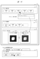
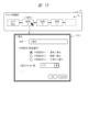
- FIG. 18 shows a display example in the case where a preview display of the internal settings is performed on the GUI screen 30 (the above-mentioned functions 1d and 1e).
- the information of the internal settings for each of the processing blocks BL may be displayed on the GUI screen 30.
- the development system 1 displays the information of the internal settings for the processing block selected by the user U1 in the block selection section 31 or the block arrangement section 32.
- the information of the internal settings for, for example, a "processing A" block selected by the user U1 by an operation such as clicking on the flow line FL of the block arrangement section 32 is displayed in, for example, a balloon-shaped GUI.
- a balloon image is displayed near the click position, and the identification information of the multiple internal settings that the "processing A" block has and the identification information of the currently applied internal setting are displayed so that they can be understood.
- the identification information of the multiple internal settings that the "processing A" block has and the identification information of the currently applied internal setting are displayed so that they can be understood.
- the preview display section 33 can display a preview of the processing block selected/specified by the user U1 as a preview of the internal settings at that time.
- a processing result image 1801 according to the state of the internal settings A1 of the "Processing A" block is displayed as a preview image.
- the preview display section 33 may also display explanatory information about the preview image, such as information about the internal settings.
- [Check and change the internal settings of the processing block] 19 shows a display example in which detailed information on the internal settings of the processing block BL can be displayed and the user U1 can confirm or set/change parameter values.
- a "binarization" block as a "processing A" block arranged in the block selection section 31 or the block arrangement section 32.
- the user U1 selects the "binarization” block in the block arrangement section 32 by, for example, clicking.
- the development system 1 displays detailed information including the internal settings of the "binarization" block in a predetermined GUI, for example, a pop-up, in response to the operation.
- a "binarization" field 1901 is displayed in a pop-up.
- the block name can be set, and one of multiple internal settings (for example, FIG. 17) can be selected and set as the internal setting (in other words, function selection).
- a threshold value for binarization can be set as the detailed parameter value.
- a "binarization” block depending on the processing block BL, there may be multiple internal settings, and the internal settings can be selected or changed in the same way.
- multiple types of filtering processes and detailed parameter values are provided as multiple internal settings.
- in the case of a "binary image shape conversion” block “erosion,” “dilation,” “noise removal,” “contour extraction,” etc. are provided as internal settings.
- the internal settings include drawing mode, center coordinates, radius, color, etc.
- a single processing block BL may have multiple internal settings according to the processing details, and may be prepared as a separate processing block for each internal setting.
- a "normal binarization” block, a "range binarization” block, etc. may be provided in the block selection unit 31.
- the user U1 may be able to change the parameter values of the internal settings in various ways and register them as variations.
- Modification of Function 1 Temporary Application Preview
- This function is a function for displaying a preview of a process block BL that would be temporarily applied to a flow line FL when the user U1 selects a desired process block BL in the block selection unit 31.
- FIG. 20 is an explanatory diagram of the provisional application preview function of this modified example.
- the block placement unit 32 for example, the "camera capture” block, the "processing A” block, and the "processing B” block have already been placed as a provisional flow line FL.
- User U1 considers the next process block BL that he wants to connect after the "processing B" block, and selects it from the parts in the block selection unit 31.
- the candidates for the next process block BL are the "processing D" block and the "processing E" block.
- the processing result image in this provisional application case is an image obtained by inputting the processing result image of the output of the "Process B" block into the "Process D” block and processing it.
- the processing result image of the "Process D” block is displayed in the area of preview display section 33, as in preview display 2001.
- development system 1 assumes that "Process E” block has been placed at the very end of flow line FL, obtains a processing result image of "Process E” block in this assumed state, and displays a preview in preview display section 33.
- the processing result image of "Process E” block is displayed in the area of preview display section 33, as in preview display 2002. Note that Figure 20 illustrates the above two examples together.
- the user U1 can see the preview without having to perform operations such as dragging and dropping the process block BL onto the flow line FL.
- the preview display unit 33 is not limited to one area, and may be provided with multiple preview display areas. For example, as shown in FIG. 20, a first preview image may be displayed in a first preview display area, and a second preview image may be displayed in a second preview display area, and these may be displayed side by side to enable comparison.
- Fig. 21 shows an example of a GUI configuration of the preview display unit 33.
- the example of Fig. 21 has a GUI that allows operations such as playback display of a video when the preview display target/range is a video including a plurality of processing blocks (e.g., Fig. 15).
- the preview display unit 33 has, as GUI components, a video playback button 2101, a video stop button 2102, a start button 2103, an end button 2104, a playback time field 2105, a zoom in button 2106, a zoom out button 2107, and other tabs 2108.
- the preview can be displayed by, for example, pressing the video playback button 2101, double-clicking the preview display area 2100, dragging and dropping into the preview display area 2100, etc.
- a slide bar or the like may be provided, allowing a desired point in the video to be selected and displayed for playback.
- [Feature 2: Multi-preview feature 1] 22 is an explanatory diagram of the multi-preview function 1 as function 2.
- the multi-preview function 1 is a function for displaying, for example, a plurality of processing result images of a plurality of processing blocks BL in parallel in the preview display section 33.
- function 2 the following processing operation is performed when a preview is executed.
- Function 2 includes the following function 2a, etc.
- User U1 enables the multi-preview function and specifies multiple processing blocks BL of the flow line FL in the block placement unit 32 as the target and range of the preview (for example, FIG. 11 described above).
- the development system 1 specifies multiple processing result images of the multiple processing blocks BL specified by user U1 as the preview display target.
- the development system 1 displays the multiple target processing result images in parallel as multi-preview in multiple divided areas within the area (one screen) of the preview display unit 33.
- the multi-preview function is enabled, for example, by a specified operation.
- the development system 1 may transition the control mode to the multi-preview mode (mode 2) in response to a specified operation.
- mode 2 the multi-preview mode
- a specified preview execution operation for example, input of a preview display command
- a specified multi-preview execution operation for example, input of a multi-preview display command
- the user U1 can select the number of divisions for multi-preview.
- the number of divisions may be selected as "none/4/9" when performing multi-preview.
- the multi-preview mode may be selected for each number of divisions.
- the number of divisions in multi-preview mode may be set by the user in advance. When division is "none,” this corresponds to the normal preview display of function 1 described above.
- the 22 illustrates two examples of multi-preview displays when four processing blocks BL, from the "camera capture” block b1 to the "processing C" block, are arranged as provisional flow lines FL in the block arrangement section 32.
- the first example (A) shows a multi-preview display 2211 when a multi-preview execution operation 2201 with a division count of 9 is performed on the target flow line FL.
- the second example (B) shows a multi-preview display 2212 when a multi-preview execution operation 2202 with a division count of 4 is performed on the target flow line FL.
- the preview display section 33 displays a multi-preview with the selected number of divisions.
- the area of the preview display section 33 (a square in this example) is divided into nine divisions to form 3x3 divided areas. In the 3x3 divided area, four divided areas are used to display the processing result images of the four processing blocks of the flow line FL as preview images.
- the area of the preview display section 33 (a square in this example) is divided into four divisions to form 2x2 divided areas. In the 2x2 divided area, four divided areas are used to display the processing result images of the four processing blocks of the flow line FL as preview images.
- the display contents of the preview display section 33 in the case of multi-preview are controlled, for example, as follows.
- (C) shows a schematic diagram of the multi-preview display contents when the number of divisions is four, similar to (B).
- the multi-preview display starts, for example, from the upper left division area in the preview display section 33 area, and ends at the lower right division area.
- Each division area initially has a specified background color.
- the division areas may display characters such as "camera capture preview" that indicate the associated processing block.
- the development system 1 determines the target/range of the multi-preview in the same manner as described above (e.g., FIG. 11) in response to the operation of the user U1. Also, for example, when performing a multi-preview, the user U1 may select/designate, by clicking or other operations, a block at which to start the multi-preview, such as the "camera capture” block b1, or a block at which to end the multi-preview, such as the "processing C" block, from the flow line FL of the block arrangement unit 32. In accordance with the above operations, the development system 1 obtains each of the processing result images for each processing block BL from the start block to the end block in the target/range of the multi-preview. The development system 1 automatically and sequentially displays these multiple processing result images as a multi-preview in the divided areas of the preview display unit 33.
- the development system 1 first displays the processing result image of the "Camera capture” block b1 in the upper left split area 2221 as a camera capture preview. The development system 1 then displays the processing result image of the "Processing A” block as a Processing A preview in the upper right split area 2222. The development system 1 then displays the processing result image of the "Processing B” block as a Processing B preview in the lower left split area 2223. The development system 1 then displays the processing result image of the "Processing C” block as a Processing C preview in the lower right split area 2224. After that, each image in the four split areas continues to be displayed until the end of the multi-preview. A similar multi-preview display is possible when the number of divisions is 9.
- the user U1 when performing a multi-preview operation, the user U1 selects, by clicking or otherwise operating, from the flow line FL in the block placement unit 32, the processing block BL (e.g., the "Process C" block) that will be the end point for the multi-preview display target.
- the development system 1 obtains processing result images of each block in sequence from the specified end block in the opposite direction to the above, i.e., in the direction toward the beginning of the flow line FL, and displays them as a multi-preview in the preview display unit 33.
- the processing block BL is a number (e.g., 3) smaller than the number of divisions (e.g., 4) in the preview display section 33, some of the divided areas will remain displayed as background, and the processed result image will not be displayed. Also, the number of divisions is not limited to 4 or 9, and can be 2 or more.
- the multi-preview function 1 allows the user U1 to check the processing contents of each processing block BL in parallel on the GUI screen 30. This function allows the progress of multiple image processes to be checked at once, further improving the efficiency of debugging and other operations using previews.
- the development system 1 may automatically determine the number of divisions in the multi-preview depending on the number of processing blocks BL selected as the target of the multi-preview. For example, if the number of target processing blocks BL selected in response to the operation of the user U1 is one, a normal preview display is used. If the number of blocks is two, three, or four, a multi-preview with four divisions is used. If the number of blocks is two or three, two or one of the four division areas will be unused. If the number of blocks is five, six, seven, eight, or nine, a multi-preview with nine divisions is used.
- the development system 1 may also automatically determine the number of divisions to be the same as the number of processing blocks BL in the range specified in response to the operation of the user U1. For example, the development system 1 sets the number of divisions to 2 when the number of target processing blocks BL is 2, and to 3 when the number is 3. Note that, although FIG. 12 shows a case where the divided area is also square when the area of the preview display section 33 is square, this is not limiting.
- Fig. 23 shows a modified example of the multi-preview function 1.
- This modified example is an example in which a multi-preview display is performed in a horizontal row in accordance with the arrangement of the flow lines FL.
- the arrangement of the multiple divided areas in the preview display section 33 area is not limited to the example in Fig. 22 and may be a predetermined arrangement, for example, a horizontal row or a vertical row.
- Fig. 23 also shows an example in which the number of divisions is automatically determined in accordance with the number of target processing blocks BL.
- the user U1 performs a multi-preview execution operation 2301 by specifying the start block as "Process A” and the end block as “Process C” as the target of the multi-preview for the state of the provisional flow line FL in the block arrangement unit 32.
- the targets of the multi-preview are three process blocks BL, "Process A”, “Process B”, and "Process C”.
- the development system 1 displays three divided areas corresponding to the three target process blocks BL in a horizontal row in the area of the preview display unit 33 in accordance with the arrangement direction of the flow line FL (from left to right in this example), and displays the processing result images of each of the three blocks in parallel in these divided areas.
- a process A preview image 2311, a process B preview image 2312, and a process C preview image 2313 are displayed in order.
- Fig. 24 is an explanatory diagram of the multi-preview function 2 as function 3.
- the multi-preview function 2 is a function that displays, as a multi-preview, each processing result when multiple internal settings of the processing block BL are switched.
- the development system 1 may control the state in which function 3 is enabled as a predetermined mode (hereinafter referred to as mode 3).
- mode 3 The concept of the internal settings of the processing block BL is as shown in Fig. 17 and the like.
- the multi-preview function 2 includes the following function 3a, etc. As a premise, it is assumed that a multi-preview display 2212 with a division number of 4, as shown in FIG. 22B, for example, has already been created. From this state, in response to a specified operation, for example, the following processing operations are performed.
- the "Processing A" block is clicked the first time, the result image of processing A with "internal setting 1" is displayed in split area 2411.
- the result image of processing A with "internal setting 2" is displayed in second split area 2412.
- the result image of processing A with "internal setting 3" is displayed in third split area 2413.
- user U1 can compare and check the processing results for each internal setting of processing block BL in parallel. For example, user U1 can check the processing result image for multiple detailed parameter setting values of image processing at once. This further improves the efficiency of debugging, etc., using the preview function.
- FIG. 25 is a diagram for explaining the modes (preview modes) of the preview display function F1 as a supplement.
- the preview display function F1 on the GUI screen 30 there are a plurality of functions in detail, as in the above example.
- the development system 1 may prepare a mode corresponding to each function, and switch the control and display modes according to the function that the user U1 wants to use and the GUI operation of the user U1.
- the development system 1 provides a GUI on the GUI screen 30 that allows these modes to be switched according to the operation of the user U1.
- the user U1 can select the mode of the desired function through the GUI.
- the example GUI screen 30 in FIG. 25 has a preview mode field 2501.
- the preview mode field 2501 is a GUI such as a list box in which multiple modes are displayed as options, and a mode can be selected by an operation of the user U1.
- the development system 1 applies the mode selected by the operation of the user U1. For example, when "mode 2" is selected, the development system 1 switches to a mode 2 state in which the multi-preview function 1 is enabled. In other words, the GUI screen 30 including the preview display section 33 and the like is switched to a state in which GUI operations in mode 2 are accepted.
- This alert function is a function that displays information indicating OK, NG, etc., regarding the contents and results of the image inspection on the preview display unit 33, and is a function that highlights the judgment result, etc.
- this alert function is a function that changes the display mode of the image frame depending on the contents and results of the image displayed on the preview display unit 33.
- FIG. 26 is an explanatory diagram of the alert function.
- a "camera capture” block b1 to a “judgment” block b2 are arranged on the flow line FL of the block arrangement section 32.
- the "judgment” block b2 is a block that performs a predetermined judgment process using a processing result image output from a previous processing block BL, for example a "processing B" block, as an input image, and outputs a judgment result image.
- the judgment process is, for example, a judgment of the presence or absence, number, and quality of appearance of objects 20 captured in the input image.
- the output of the "judgment” block b2 includes a judgment result image and judgment result information.
- Function 4 includes the following function 4a, etc.
- the development system 1 changes the color of the frame in the preview image (i.e., the judgment result image) displayed on the preview display unit 33 depending on the judgment result image and judgment result information (e.g., "OK"/"NG”/other information) that are the output of the "Judgment" block b2.
- judgment result information e.g., "OK"/"NG”/other information
- FIG. 26 shows three examples of display in the preview display section 33.
- A is the first example, in which a judgment result image 2601 is previewed in the preview display section 33.
- the judgment result image 2601 has a text image representing the judgment result, for example, "OK", superimposed on the processing result image of "Process B".
- "OK” indicates, for example, that the presence or absence, number, or appearance quality of the object 20 meets a predetermined standard.
- the display color of the outer frame 2611 of the judgment result image 2601 is determined according to the text image of the judgment result.
- the display color of the outer frame 2611 corresponds to the text image of the judgment result "OK”, and is displayed in a color representing "OK", for example, blue.
- (B) is a second example, in which a judgment result image 2602 is previewed in the preview display section 33.
- a text image indicating the judgment result for example, "NG”
- "NG" indicates, for example, that the presence or absence or number of objects 20, the quality of appearance, etc., did not meet a predetermined standard.
- the color of the outer frame 2612 is displayed in a color indicating "NG", for example, yellow, to correspond to the judgment result text image "NG”.
- (C) is a third example, in which a judgment result image 2603 is previewed in the preview display section 33.
- the judgment result image 2603 has a text image indicating the judgment result, for example, "Warning”, superimposed on the result image of "Process B".
- "Warning” indicates a warning due to the fact that a certain condition or result is met, for example, regarding the presence or absence or number of objects 20, the quality of appearance, etc.
- the color of the outer frame 2613 is displayed in a color indicating "Warning", for example, red, to correspond to the judgment result text image "Warning".
- This function allows user U1 to visually grasp the judgment results regarding image inspection in the preview display. This improves the efficiency of debugging and other aspects of system development.
- [Function 5: Color information extraction function] 27 is an explanatory diagram of a color information extraction function as function 5.
- Function 5 is a function that extracts and displays color information of a pixel selected by user U1 selecting and designating a pixel position on the preview image in preview display unit 33 by operating a mouse cursor or the like. In function 5, the following processing operation is performed when a preview operation is performed.
- Function 5 includes the following function 5a, etc.
- the development system 1 extracts the pixel value of the point where the cursor 39 is hovered over the preview image in the preview display section 33, and displays the pixel value as color information in the preview display section 33.
- FIG. 27 two examples are shown together in the case of preview display for judgment block b2.
- first example (A) when the pixel is at pixel position 2721 indicated by the arrow cursor 39 on the judgment result image 2701 of the preview display unit 33, color information 2711 of the pixel value (R, G, B) of that pixel position 21 is extracted and displayed.
- second example (B) when the pixel is at pixel position 22 indicated by the arrow cursor 39 on the judgment result image 2702, color information 2712 of the pixel value of that pixel position 22 is extracted and displayed.
- Function 5 allows user U1 to use the color information displayed along with the preview image as reference information for creating the flow line FL.
- the color information of the preview can be used as a reference value for setting detailed parameter values for the internal settings of those processing blocks BL.
- user U1 can use the color information of the preview as a reference to change the flow line FL, such as changing the "processing A” block, the "processing B” block, and the "judgment” block b2 to a different processing block BL or changing the internal settings of the processing block BL.
- [Feature 6: Tournament system] 28 is an explanatory diagram of a processing block selection function in a tournament format as function 6.
- function 6 in the preview display, the processing result images for each processing block BL are compared in a tournament format, and the user can select the processing block to be adopted.
- function 6 the following processing operations are performed when the preview is executed.
- Function 6 includes the following function 6a, etc.
- the development system 1 determines candidates for the next processing block BL to be placed based on the state of the provisional flow line FL in the block placement unit 32, displays a preview of these candidate blocks in the preview display unit 33 in a tournament format, and allows the user U1 to select candidate blocks one by one to be placed and adopted in the flow line FL.
- the development system 1 automatically determines and extracts the candidate blocks (e.g., the first and second candidates) to be displayed in the preview display unit 33.
- the user U1 may specify the candidate blocks.
- User U1 looks at and compares the processing result images of the candidate blocks (e.g., the first and second candidates) displayed in the preview display unit 33, judges which block should be adopted for the flow line FL, and performs a specified operation to select the processing block BL to be left as the winner according to his/her judgment.
- the development system 1 leaves the candidate block selected according to that operation as the candidate block for the winner, and if there is a next candidate block, it similarly sets it as the opponent's candidate block and similarly displays a preview.
- the development system 1 repeats such matches according to the number of candidate blocks, and finally places the one processing block BL selected by user U1 at a specified location (e.g., the very end) of the flow line FL in the block placement unit 32.
- this function 6 may be used to compare different types of processing blocks, such as a comparison between a "Processing A” block and a “Processing B” block, as comparison targets in a tournament.
- this function 6 may be used to compare different internal settings (e.g., detailed parameter values changed) of the same processing block, such as a comparison between "Processing A (internal setting 1)” and "Processing A (internal setting 2).”
- User U1 can select the winning processing block BL by performing a predetermined operation, such as double-clicking, on the preview display area corresponding to one of the preview-displayed candidate blocks.
- FIG. 28 shows a first example where a comparison is made between different internal settings for the same processing block.
- FIG. 29 shows a second example where a comparison is made between different types of processing blocks.
- FIG. 28 also shows a case where a candidate block is automatically extracted.
- FIG. 29 shows a case where user U1 selects a candidate block.
- the block selection unit 31 is provided with various processing blocks BL, such as a "processing A” block and a “processing B” block.
- the "processing A” block is binarization
- the "processing B” block is an image process different from binarization.
- the "processing A” block has internal settings such as "internal setting A1", “internal setting A2", and "internal setting A3".
- the "camera capture” block b1 is placed as a provisional flow line FL. The user U1 performs a preview execution operation in the tournament method (particularly the internal setting comparison method).
- the development system 1 automatically determines and extracts blocks that can be placed next to the "camera capture" block b1, and extracts a predetermined number (comparison number) of processing blocks BL or internal settings for comparison display in the tournament method as candidates from the extracted processing blocks BL.
- the comparison number in the tournament method may be set in advance as a fixed value (for example, 2), or may be automatically variable within the range of the maximum number.
- the user U1 may be able to specify and set the comparison number.
- the development system 1 extracts a "Processing A" block as a candidate block to be placed next. Then, multiple internal settings for this "Processing A" block are set as candidates for comparison.
- a preview execution operation may be performed in a tournament format on the processing block BL selected by the user U1 in the block selection unit 31.
- a preview execution operation may be performed in a tournament format on the last processing block BL placed on the flow line FL in the block placement unit 32.
- the number of comparisons in the tournament format is 2.
- the development system 1 provides comparison areas 2801 and 2802 corresponding to the number of comparisons 2 in an area 2800 (square in this example) for preview display in the tournament format in the preview display unit 33.
- the development system 1 extracts internal settings that are candidates for the battle in the "Processing A" block. Initially, for example, "internal setting A1" and “internal setting A2" are candidates.
- the development system 1 obtains a processing result image of "Processing A" with each candidate internal setting for the input camera-captured image.
- the development system 1 displays the processing result image with each internal setting as a preview image in each comparison area.
- the development system 1 displays a processing result image 2811 with "internal setting A1" (also shown here as “Processing A1") in the comparison area 2801, and displays a processing result image 2812 with "internal setting A2" (also shown here as “Processing A2") in the comparison area 2802.
- the preview display unit 33 may also display the camera-captured image, which is the image to be processed, and may also display explanatory information about the internal settings of each image.
- User U1 compares the two previewed processing result images 2811, 2812, judges which is more suitable as the internal setting of the processing block to be placed next, and performs a predetermined selection operation to select one of the internal settings as the winning block. For example, when user U1 selects "internal setting A1", he performs an operation such as double-clicking on the comparison area 2801 of the processing result image 2811. In accordance with this operation, the development system 1 leaves the "processing A" block of "internal setting A1" as the winning candidate, and removes the unselected "internal setting A2" from the candidates as the losing one. In this way, first one internal setting of the two candidates is selected. If there are no other candidates, the internal setting of this one candidate is determined to be adopted. The development system 1 places the "processing A" block of the "internal setting A1" determined above at the specified location of the flow line FL of the block placement unit 32.
- user U1 may select the "Process A” block of "Internal Setting A1" from the block selection unit 31 and place it in the block placement unit 32 based on the results of the tournament.
- the development system 1 automatically selects the internal settings of the comparison candidates, but without being limited to this, user U1 may select and operate the internal settings of the comparison candidates.
- various processing blocks BL such as "Process A”, “Process B”, and “Process C” are prepared in the block selection unit 31.
- "Process A” is binarization
- "Process B” and “Process C” are image processes different from binarization.
- "Process B” is, for example, a rotation process.
- a "camera capture” block b1 is placed as a provisional flow line FL. The user U1 performs a preview execution operation in the tournament method (particularly the inter-block comparison method).
- the user U1 specifies two blocks, for example, the "process A” block and the "process B” block, as candidate blocks for comparison among the processing blocks BL that can be placed next to the "camera capture” block b1.
- the development system 1 extracts candidate blocks with a predetermined number of comparisons (for example, 2) for comparison display in the tournament method.
- a predetermined number of comparisons for example, 2 for comparison display in the tournament method.
- the operation when the user U1 specifies multiple processing blocks BL is not limited to clicking each block, and may be an operation of encircling them with a frame using the cursor 39.
- the development system 1 provides comparison areas 2901 and 2902 corresponding to the number of comparisons, 2, in an area 2900 (square in this example) for preview display in the tournament format in the preview display unit 33.
- the development system 1 obtains a processing result image by the "Processing A” block and a processing result image by the "Processing B” block for the camera-captured image, which is the image to be processed.
- the development system 1 displays a processing result image 2911 by the "Processing A" block in the comparison area 2901, and a processing result image 2912 by the "Processing B" block in the comparison area 2902.
- the preview display unit 33 may also display a processing target image 2920, which is the camera-captured image, and may also display explanatory information for each processing block.
- User U1 compares the two previewed processing result images 2911, 2912, determines which is the most suitable block to place on the flow line FL, and performs a specified operation to select one of the processing blocks BL to be retained as the winner. For example, to select the "Processing A" block, the user performs an operation such as double-clicking on the comparison area 2901 of the processing result image 2911. In accordance with this operation, the development system 1 retains the "Processing A" block as the winner and removes the unselected "Processing B" block from the list of candidates. If there are no other candidate blocks, the "Processing A” block is determined to be the block to be adopted. The development system 1 places the selected "Processing A” block at the specified location on the flow line FL in the block placement unit 32.
- development system 1 may automatically determine and extract candidate blocks for comparison. For example, development system 1 may extract all types of blocks that can be placed next to "camera capture" block b1 based on configuration information of all types of processing blocks BL that have been prepared in advance. Then, development system 1 may generate combinations of comparison candidates from the extracted multiple blocks according to the number of comparisons.
- Figure 30 shows such an example, and is a continuation of Figure 28, corresponding to a case where there are three internal settings for the candidates.
- Figure 28 shows a case where the block of "Internal Setting A1" is compared with the block of the third other candidate, "Internal Setting A3" (also shown here as "Processing A3").
- the processing result image 2811 after "Process A1" in FIG. 28 is displayed as is, and in the comparison area 2802, the processing result image 2812 after "Process A2" in FIG. 28 is erased and the processing result image 2813 after "Process A3" is displayed.
- User U1 compares the two previewed processing result images 2811, 2813, determines which one is more suitable as the internal setting block to be adopted for the flow line FL, and selects one of them. For example, to select the "Processing A" block of "Internal Setting A3", user U1 performs an operation such as double-clicking on the comparison area 2802 of the processing result image 2813. In response to this operation, the development system 1 determines that the "Processing A" block of "Internal Setting A3" is the winner, and if there are no other candidates, it determines that it is the block to be adopted. The development system 1 places the selected "Processing A" block of "Internal Setting A3" at the specified location of the flow line FL in the block placement unit 32.
- the preview function of the tournament method described above can assist the user U1 in selecting the processing block BL of the flow line FL, selecting internal settings, adjusting detailed parameters, etc., making it possible for even inexperienced users to develop a system.
- the user U1 can, for example, compare two images and select the more suitable block in turn, making it easy to compare and consider.
- FIG. 31 shows a modified example of function 6 above.
- the example in FIG. 31 shows a case where three types of internal settings in the "Processing A" block, "Internal Setting A1", “Internal Setting A2”, and “Internal Setting A3", are compared simultaneously.
- This method is not a tournament method (where winners compete against each other in turn), but it is the same in that a processing block BL can be selected based on a comparison in a preview.
- a "camera capture” block b1 and a "processing A” block are arranged as provisional flow lines FL in the block arrangement section 32.
- the user U1 wishes to consider adopting the internal settings of the "processing A” block by a preview comparison method, for example, the user U1 performs a predetermined preview execution operation.
- the development system 1 extracts multiple candidate internal settings (in this example, "internal setting A1", “internal setting A2", and “internal setting A3" in the candidate block (in this example, the "processing A” block), and displays preview images of the multiple candidate internal settings in parallel in area 3100 of the preview display section 33.
- processing result images 3111, 3112, and 3113 of the "processing A" block with each internal setting are displayed in parallel, for example, in a single horizontal row.
- the preview image of each internal setting is also provided with a selection button 3130 (for example, a button that allows a check mark to be entered).
- the selection button 3130 is a button for selecting and specifying a candidate block or a block to be adopted. For example, if user U1 determines that "internal setting A3" shown in image 3113 is the most suitable, he or she presses the selection button 3130 corresponding to that image 3113.
- the development system 1 adopts the block of the internal setting corresponding to the operated selection button 3130. In response to this operation, the development system 1 adopts the "processing A" block in the selected "internal setting A3" for the flow line FL.
- the selection buttons 3130 in the preview display section 33 may be designed to allow only one selection, but in other cases, multiple selections may be possible. That is, the user U1 may be able to leave two or more options as candidates as a result of the preview. For example, if the user U1 is unable to narrow down the internal settings to be adopted to one, he or she may select multiple options with the selection buttons 3130, leave them as candidates, and then decide on one at a later time.
- the above example is a comparison between internal settings, but it can be similarly applied to a comparison between different types of blocks.
- [Variation: Multiple flow lines] 32 shows a variation of the function 6, which is a function that can provisionally create multiple flow lines FL in the block placement section 32 according to the selection of a process block BL by the user U1.
- the function 6 is a function that can provisionally create multiple flow lines FL in the block placement section 32 according to the selection of a process block BL by the user U1.
- the tournament-style function 6 of FIG. 28 or the like to select a process block BL to be placed on a flow line FL, if it is not possible to decide on one process block BL (including differences in internal settings), it is also possible to provisionally create two or more flow line configurations according to two or more process blocks BL selected by the user U1.
- the development system 1 creates a provisional flow line FL according to, for example, the type or differences in internal settings of the selected process block BL, and displays it in the block placement section 32.
- the "Processing A” block has "Internal Setting 1" and "Internal Setting 2".
- the user U1 considers and selects which of the "Internal Setting A1" and “Internal Setting A2" blocks should be placed as the "Processing A" block next to the "Camera Capture” block b1 as a provisional flow line FL in the block placement section 32.
- the development system 1 displays a preview image 3211 based on the "Internal Setting A1" and a preview image 3212 based on the "Internal Setting A2" in the preview display section 33 for comparison.
- the development system creates and displays in the block placement section 32 a first candidate flow line 3241 (FL1) when "Internal Setting A1" is selected, and a second candidate flow line 3242 (FL2) when "Internal Setting 2" is selected.
- the development system 1 may divide the area of the block placement section 32 into sections for each flow line FL (e.g., FL1, FL2), for example, by using dashed lines, and display each candidate flow line FL within each divided area.
- each flow line FL e.g., FL1, FL2
- User U1 can also try out different flow line configurations for each candidate flow line FL, for example by connecting other processing blocks BL to the end of each.
- the state of each flow line configuration can be checked using the preview function, as described above.
- User U1 can also delete candidate flow lines depending on the trial.
- User U1 can decide on one flow line FL to adopt depending on the trial. For example, user U1 may decide on one flow line FL to adopt, or on one or more flow lines FL to remain and save as candidates, by operating selection buttons 3250 provided for each flow line FL in block placement unit 32.
- the development system 1 divides the area of the block placement unit 32 as in FIG. 32, creates an area for creating and editing the second flow line, and places a blank block BS.
- User U1 can create a second provisional flow line by performing similar operations on the two areas.
- User U1 can perform an operation to save the selected flow line as data (e.g., inputting a save command).
- Fig. 33 shows another example of the configuration of the flow line FL in the block placement unit 32 and another example of the GUI.
- the flow line FL in Fig. 33 shows an example of a configuration having a branch, in other words, parallel processing blocks.
- the flow line FL is not limited to the simple serial configuration described above, but can also be configured for parallel processing by branching as necessary.
- Fig. 33 also shows a case where the displayed direction of the flow line FL is the vertical direction within the screen.
- User U1 can create a branch in the block placement unit 32 by a predetermined operation (e.g., inputting a branch command).
- the GUI of the flow line FL in FIG. 33 shows a case where there is a node ND between the processing blocks BL.
- This node ND represents input/output data (images, etc.) for the processing block BL.
- the user U1 can also operate this node ND in the block placement unit 32.
- a desired processing block e.g., a "processing X" block
- a desired image file can be placed in the desired node ND, and the image can be specified as an input image for the processing block BL following the node ND.
- the operation can be performed on the node ND.
- flow lines FL can also have loop configurations, just like general information processing flow charts.
- [Function 7: Line sensor installation support] 34 shows an explanatory diagram of a line sensor installation support function (in other words, a camera/sensor device setting support function) as function 7.
- Function 7 is a function that supports the installation settings of the camera/sensor device 21 (digital signal output device 105 in FIG. 2) that is installed in the image inspection system 2 in FIG. 1.
- a camera capture process 201 that inputs an image 50 at the beginning, and correspondingly, a "camera capture” block b1 is provided at the beginning of the flow line FL on the GUI screen 30 of the development system 1.
- the user U1 must select the internal settings for the "camera capture” block b1 and set detailed parameter values for the internal settings.
- Function 7 is a function that assists with procedures such as setting detailed parameters for the internal settings of the "camera capture” block b1 by using a preview function, etc. This function 7 includes the following function 7a, etc. Note that the lower part of FIG. 34 shows two examples of preview displays by each function.
- the development system 1 has a function of displaying a preview of the appropriate image and the camera-captured image side by side in the preview display section 33. This function 7a is shown in (A) of FIG. 34.
- the development system 1 displays a pre-set appropriate image 3401 for the "camera capture” block b1 in parallel with a camera-captured image 3402, which is an output image when the camera capture process is performed with the internal settings of the "camera capture” block b1 on the flow line FL.
- the camera-captured image 3402 is an image resulting from the camera capture process based on the input of an image 50 taken in real time from the camera/sensor device 21.
- the user U1 can compare these images in the preview display section 33 and check whether the camera-captured image 3402 obtained by the internal settings of the "camera capture" block b1 of the flow line FL being created is more suitable than the appropriate image 3401. Depending on the confirmation result, the user U1 can decide on the parameter value of that internal setting or change to the parameter value of another internal setting.
- the development system 1 has a function of displaying an alert if the camera-captured image 3402 largely deviates from the appropriate image 3401 when comparing the appropriate image 3401 and the camera-captured image 3402 in function 7a above.
- This function 7b is shown in (B).
- the development system 1 evaluates the degree of deviation of the contents of the camera-captured image 3402 from the appropriate image 3401 in area 3400 of the preview display unit 33 based on image processing. If the degree of deviation is, for example, greater than a threshold, the development system 1 displays an alert indicating that the deviation is large in the preview display unit 33. In this example, when displaying an alert, similar to the function of FIG.
- the development system 1 highlights at least the outer border 3410 of the rectangle surrounding the camera image 3402 in area 3400 of the preview display unit 33 using a predetermined color or other expression. Furthermore, the development system 1 may display a text image (e.g., "divergence") indicating an alert, rather than being limited to the color of the outer frame 3410. By seeing this alert, the user U1 can easily recognize that there is a large deviation from the correct image 3401, and can adjust the parameter values of the internal settings of the "camera capture" block b1, etc.
- a text image e.g., "divergence”
- the development system 1 has a function of being able to display a preview while changing detailed parameter setting values (e.g., image capture period) of the internal setting of the above-mentioned "camera capture” block b1 by clicking the block multiple times or performing other operations.
- detailed parameter setting values e.g., image capture period
- the development system 1 cyclically changes the internal setting of the "camera capture” block b1 (similar to FIG. 17, etc.).
- the setting can be switched between “internal setting 1", “internal setting 2", “internal setting 3", “internal setting 1”, etc.
- each of these internal settings has a different image capture period as a parameter setting value.
- the development system 1 displays a preview image corresponding to the state of the changed internal setting in the preview display section 33.
- the development system 1 changes the "internal setting 1" of the "camera capture” block b1 to "internal setting 2," and displays the image resulting from processing using "internal setting 2" as the camera capture image 3402. This allows the user U1 to easily compare and confirm each internal setting with the appropriate image 3401 while switching between them.
- the flow line FL is provided with a "camera capture” block b1 whose internal settings can be changed, and also with a preview function for the "camera capture” block b1 by comparison with an appropriate image.
- function 7 makes it easy to change the internal settings of the "camera capture” block b1 and check the image by comparing it with an appropriate image with a simple operation such as clicking. This significantly reduces the difficulty of installing and setting up the camera/sensor device 21 such as a line sensor in the image inspection system 2, contributing to reducing the burden on the user.
- the aspect ratio of the line sensor image may affect the accuracy of inspection, judgment, etc.
- An example of a parameter that affects the aspect ratio is the imaging period (in other words, the trigger interval).
- the imaging period in other words, the trigger interval.
- the image of the target object 20 may be stretched in the camera-captured image, resulting in an inappropriate aspect ratio, and the accuracy of judgment, etc. may decrease.
- the development system 1 selects an image capture cycle as an internal setting in the above-mentioned "camera capture” block b1, and in the area of the camera-captured image 3402 in the preview display section 33, a camera-captured image 3402 when changed to the selected image capture cycle is displayed.
- This makes it easy for the user U1 to set a suitable image capture cycle in the "camera capture” block b1 so that the aspect ratio of the camera-captured image 3402 is suitable in comparison with, for example, an appropriate image 3401 having an appropriate aspect ratio.
- function 7 the multi-preview function described above is also used.
- the development system 1 causes the preview display unit 33 to display multiple camera-captured images, each with different internal settings of the "camera capture" block b1, in parallel as a multi-preview.
- the "camera capture” block b1 has, as its internal settings, parameter values related to the settings of the camera/sensor device 21 (digital signal output device 105 in FIG. 2) of the image inspection system 2. Examples of parameters include the imaging period, imaging direction, and other optical conditions.
- the development system 1 may be configured to select, set, and save detailed parameter values of the internal settings of the "camera capture” block b1 in response to an operation by the user U1 on the GUI screen 30.
- FIG. 35 shows an example of user settings for the internal settings of the "camera capture” block b1 on the GUI screen 30.
- the user U1 selects the "camera capture” block b1 and selects and operates to create a new internal setting.
- the development system 1 displays an internal settings field 3500 as an example of a GUI for the internal settings of the "camera capture” block b1.
- the user U1 can confirm and set the parameter values of the internal settings of the "camera capture” block b1 and register them as new internal settings.
- the internal settings field 3500 for example, the name of the internal setting, the camera/sensor device to be used, the imaging period, and other parameter values can be entered. After the internal setting is registered, the internal setting is displayed as an option and becomes available when operating the internal settings of the camera capture block b1.
- FIG. 36 is an explanatory diagram of a template matching setting support function as function 8.
- a comparison image in other words, a template image, a reference image, etc.
- Inspection, judgment, etc. are performed based on the degree of match between them.
- Function 8 is a function that assists and supports the setting of a template image, etc. in such a template matching method.
- Function 8 includes the following function 8a, etc.
- the development system 1 has a function that allows the user U1 to operate a mouse or the like on the preview display unit 33 to specify a template area when setting a template image.
- the development system 1 has a function to display previews of template candidates in multiple sizes in response to an operation by user U1, such as clicking on a template.
- the development system 1 has a function to determine a template image in response to an operation such as double-clicking a preview image by user U1.
- user U1 selects the "camera capture” block b1 in the block selection unit 31 and performs the procedure for registering a template image.
- the development system 1 displays a camera-captured image 3601 by the "camera capture” block b1 based on an actual camera image in the area of the preview display unit 33. In that area, user U1 selects a desired area of the camera-captured image 3601 that is suitable as a template.
- the selection operation at this time can be, for example, a rectangular area designation by clicking or dragging the mouse cursor 39.
- user U1 designates a rectangular area 3602 that contains and circumscribes a circle corresponding to the target object 20 such as a product as the template area.
- the development system 1 tentatively registers the template area selected by the operation as a candidate for the template image (referred to as candidate 1).
- (B) and (C) show examples in which other candidate template areas have been specified.
- a rectangular area 3603 surrounding the character image "ABC" is specified as template area candidate 2.
- a rectangular area 3604 surrounding the character image "B” is specified as template area candidate 3. Note that when determining and registering the template image candidates, a "Register as template image candidate" command or the like may be used as an example of a GUI.
- user U1 may specify individual template area candidates such as (A), (B), and (C) through a specified GUI operation, but in another method, development system 1 may automatically vary the size of the template area based on the specification of one template area through user U1's operation such as (A) to generate candidates such as (B) and (C).
- the lower part of FIG. 36 shows an example of the function 8b.
- the user U1 selects the registered template image candidates. For example, in the preview display section 33, the user U1 selects the template area corresponding to the template image by clicking or the like, and performs a predetermined preview execution operation.
- the development system 1 displays a preview of one or more selected template image candidates in the area of the preview display section 33.
- the development system 1 displays the template images of the three candidates in parallel as a multi-preview in a division area of a predetermined number of divisions (for example, 4), similar to the multi-preview function described above.
- an image of candidate 1 is displayed in the upper left division area
- an image of candidate 2 is displayed in the upper right division area
- an image of candidate 3 is displayed in the lower left division area.
- User U1 compares these candidate images on the preview screen, selects the candidate that is suitable as the template image, and performs a specified operation to determine it as the template image. For example, when user U1 selects candidate 2, he or she operates the divided area of candidate 2 by double-clicking or the like. As a result, development system 1 determines that candidate image as the template image for "camera capture” block b1 and saves it as data. At this time, a "register as template image” command or the like may be used as an example GUI, as shown in the figure.
- a template image is registered in association with the "camera capture” block b1, but it is also possible to register a template image to be used in the judgment process in association with the "judgment" block b2.
- FIG. 37 shows, as another example of a GUI screen, an example of a GUI screen 60 on which one or more flow lines FL created and saved by the user U1 using the above-mentioned functions can be confirmed.
- the development system 1 may provide a GUI screen 60 on which created flow lines can be confirmed as shown in Fig. 37.
- the GUI screen 60 in Fig. 37 is a flow line confirmation screen, and has a flow line information column 3701, a preview column 3702, an inspection result column 3703, etc.
- the flow line information column 3701 information about one or more flow lines FL that have been created and saved is displayed in an organized manner.
- the information about one flow line FL has a line for the flow line name and a line for the names of each processing block BL that makes up that flow line FL, with the information about the processing blocks BL listed in the order in which they make up the flow line FL.
- the preview field 3702 can display a preview of the flow line FL selected by the user U1 in the flow line information field 3701.
- the inspection result column 3703 displays inspection result information when an inspection is performed on the object 20 by the image inspection system 2 using the image inspection flow corresponding to the selected flow line FL.
- the inspection in this case is not limited to an actual inspection using a completed flow line, but may be a trial inspection using a flow line that is still in the process of being created.
- the inspection result column 3703 displays information such as the inspection date and time, inspector, total number of inspections, number of OKs, number of NGs, etc.
- FIG 37 an example of a flow line FL that has been created and saved, i.e., an example of an image inspection flow for the image inspection system 2, is shown below.
- the flow line FL1 is composed of, in order, a "camera capture” block BL1, a "binarization” block BL2, a “binarized image shape conversion” block BL3, a “ellipse drawing” block BL4, and a “determination” block BL5.
- details such as the internal settings of each block can be displayed and confirmed by operating a specified button, etc.
- the development system 1 of the first embodiment can reduce the difficulty of development and the work of the user in developing the image inspection system 2.
- the operation check of the flow line of the image inspection system 2 can be realized more easily and efficiently than before.
- various configurations of the flow line can be tried while changing the processing blocks and internal settings on the GUI screen.
- the operation state of the flow line and blocks can be confirmed by preview even for the flow line in the middle of creation, so that the development can be made easier and more efficient.
- the development can be made more efficient than the conventional technology in which the operation check by preview can only be performed after the entire flow line of the system is completed. According to the development system of the first embodiment, by supporting the user on the GUI screen, even a user without advanced technical knowledge can develop and create the flow line of the image inspection system 2.
- the development system according to the second embodiment has the following functions in addition to the functions described in the first embodiment. 1. Preview display on/off switching function 2. Preview display resolution setting function 3. Preview display rotation function 4. Flow line block placement availability display function 5. Required setting/unset block display function 6. Flow line processing block display function
- these functions can be selected and executed by user U1, and can also be set by the user.
- FIG. 39 is an explanatory diagram of the preview display/non-display switching function, and shows an example of a GUI screen 30.
- the GUI screen 30 has a block selection section 31, a block arrangement section 32, and a preview display section 33.
- the block selection section 31 and the preview display section 33 do not need to be always displayed on the GUI screen 30, and may be displayed as pop-ups as necessary.
- it is not necessarily necessary to preview the processing results of all processing blocks of a flow line. If the processing results of all processing blocks including the intermediate process of the image inspection are previewed, it may be troublesome.
- each block BL in the flow line column (block arrangement section) 32 of the GUI screen 30 of the development system 1 has a GUI 3901 such as a switch for setting the preview display ON/OFF.
- User U1 can switch the preview display ON/OFF by selecting the desired block BL (the "Process A" block in the example in FIG. 39) and clicking or otherwise manipulating the switch.
- the default setting is that all processing blocks BL are set ON, and user U1 need only operate the processing blocks BL that he or she wants to set OFF.
- a preview of the processing results of the flow line FL is displayed in the preview column 33.
- a preview is not displayed for a processing block BL that is set to OFF in the GUI 3901.
- the development system 1 does not perform calculation processing for previewing the processing results for that processing block BL.
- a camera capture result image, a "processing B" result image, and a "processing C” result image are previewed, and the "processing A" result image is not displayed (OFF display).
- the OFF display may be a predetermined display such as a black background image, or may be a predetermined display indicating that the preview display is set to OFF (for example, an "OFF" text image display).
- This function makes it possible to preview only the processing results of any given processing block in a flow line. It is possible to preview only the parts of the processing results that are necessary for user U1, such as a developer or inspector. This prevents confusion and hassle compared to previewing all processing blocks in a flow line. Also, depending on the development and execution environment, the computational load when previewing the processing result image can affect the processing time. By previewing only the necessary parts, the computational load can be reduced, which ultimately contributes to shortening the processing time.
- Figure 40 shows another example of the GUI for this function.
- the user U1 clicks or drags the mouse cursor to specify a starting processing block BL and an end processing block BL to specify the desired range.
- a GUI 4001 such as a switch can be used to set ON/OFF the preview display of the processing results for all the processing blocks BL within that range.
- FIG. 41 is an example of another GUI.
- a GUI 4101 such as a switch that can collectively set the preview display ON/OFF for all processing blocks BL of the flow line FL being edited may be provided.
- User U1 can temporarily set the preview display OFF for all processing blocks BL of the flow line FL by, for example, setting this GUI 4101 to OFF.
- User U1 can then set the preview display ON for only the desired individual processing blocks BL using a GUI such as FIG. 39.
- a GUI 4102 such as a button for setting only the first processing block BL of a flow line FL to preview display ON, or a GUI 4103 such as a button for setting only the last processing block BL of a flow line FL to preview display ON may be provided.
- a GUI such as a button for setting the first processing block BL and the last processing block of a flow line FL to preview display ON may be provided.
- FIG. 42 is another example of the GUI for this function.
- the example in FIG. 39 described above is an example in which the preview display ON/OFF can be confirmed and set for each processing block BL in a GUI 3901 equivalent to the internal setting column (FIG. 19, etc.), but this is not limiting and an example as shown in FIG. 42 may be used, for example.
- an item 4201 that displays the ON/OFF setting state of the preview display is provided for each processing block BL in the flow line column 32.
- user U1 can switch the preview display ON/OFF setting for the desired processing block BL by clicking or otherwise operating item 4201.
- the display of the row of item 4201 that displays the ON/OFF setting state of the preview display can also be turned ON/OFF.
- This function allows user U1 to easily check the preview display setting status of each processing block BL of the flow line FL at a glance.
- item 4201 that displays the ON/OFF setting state of the preview display may be configured to display only ON-set items or only OFF-set items on the screen.
- Figure 43 shows another example of the GUI of this function.
- the processing block BL with the preview display set to ON is displayed with an icon 4301 (e.g., an "on" mark) added as a predetermined display indicating that the preview display is set to ON.
- the processing block BL with the preview display set to OFF may be displayed in a darker color.
- FIG. 44 shows another example of the GUI for this function.
- a flow line FL may be made up of multiple processing blocks BL.
- the flow line FL includes a camera capture block, a "Processing A” block, and a "Processing G” block. Setting the preview display ON/OFF for multiple processing blocks BL can be time-consuming and can also result in a cluttered screen display.
- this function In response to an operation on a desired process block BL of the flow line FL, this function omits the display of that process block as shown in (B). At the same time, this function sets the preview display of that process block to OFF.
- this function sets the preview display of that process block to OFF.
- the flow line FL is displayed in a shortened state.
- the range is displayed in a specified manner (e.g., "Omitted” display, gray display, etc.) to indicate that it is in a display omission state. Furthermore, when user U1 operates (e.g., double-clicks, etc.) a portion of the specified display that is in this display omission state, the development system 1 expands the range to return it to the original display state without display omission as shown in (C), and automatically sets the preview display of that range to ON.
- a specified manner e.g., "Omitted” display, gray display, etc.
- Fig. 45 is an explanatory diagram of the preview display resolution setting function.
- One problem is that, depending on the development and execution environment, when previewing a processing result image of a processing block of a flow line, the calculation load affects the processing time. If the resolution when previewing the processing result image is high, it is possible to check in high definition, but the calculation load required for the preview display process is high accordingly, and the processing time may be long.
- the preview display resolution setting function allows user U1 to set the resolution at which the processing result images of the processing blocks of the flow line are previewed.
- the preview display resolution can be selected for each processing block in the preview column.
- the development system 1 executes processing so that the processing result images of the processing blocks of the flow line are previewed in the preview column at the set resolution.
- the resolution By adjusting the resolution, the computational load can be adjusted, which contributes to shortening the processing time for the preview display and improving the accuracy of checking and viewing the preview display.
- a GUI 4501 for setting the resolution of the preview display image 4500 is provided in the preview display field 33.
- one of three levels of resolution, "high”, “medium”, and “low”, can be selected.
- "high" resolution is set as the default setting.
- This "high” resolution is a predetermined resolution, for example, the highest resolution in this system.
- the processing result image of each processing block BL to be previewed on the flow line FL is displayed as the preview display image 4500 in "high” resolution in the preview field 33. If the user U1 sets, for example, "low” resolution in the GUI 4501, in response to the preview execution operation, the processing result image of the target processing block BL is displayed in "low” resolution in the preview field 33.
- the example in Figure 45 shows the setting of the preview display resolution for the entire flow line FL (all processing blocks BL), but this is not limiting and it is also possible to set the preview display resolution for each processing block BL.
- FIG. 46 shows an example of a GUI for setting the resolution of the preview display for each processing block BL.
- the flow line column 32 there is a GUI 4601 that allows the resolution of the preview display to be set for each processing block BL.
- the resolution of the preview display can be selected and set for each processing block for the displayed GUI 4601 by a specific operation such as clicking, or in the internal setting column.
- this function is expressed as resolution on the GUI, but it may also be expressed as preview display speed, etc.
- low resolution corresponds to high speed in terms of preview display speed, so "high speed” may be displayed as an option on the GUI.
- the function of setting the preview display ON/OFF as in FIG. 39 and the function of setting the resolution of the preview display as in FIG. 45 may be integrated into one function.
- GUI 4601 in FIG. 46 options for the resolution when set to ON and options for the resolution when set to OFF may be displayed.
- various GUIs, operation methods, display methods, and other aspects may be applied, similar to the preview display on/off switching function described above (FIG. 39, etc.).
- Preview display rotation function 47 is an explanatory diagram of the preview display rotation function, which enables the operation and setting of rotating or flipping an image or video previewed in the preview field.
- the image display content may be displayed in a state that is difficult for the user U1 to recognize.
- the preview display image may show the object 20 upside down, making it difficult to recognize characters written on the object 20. This makes it difficult for the user U1, such as a developer or inspector, to perform work while checking the preview display, such as adjusting the position of the object 20, which is inefficient.
- Figure 48 shows an explanatory diagram of the problem.
- (A) shows a schematic vertical cross-sectional view (Y-Z plane view) of a manufacturing line 4800 or a workbench 4800 corresponding to the image inspection system 2 of Figure 1, on which an object 20 is placed.
- a camera 21 is installed vertically above the object 20.
- An inspector 4801 is placed below (in front of) the object 20.
- the X direction is the direction in which the object 20 flows and the left-right direction as seen by the inspector 4801
- the Y direction is the up-down direction (in other words, the front-back direction) as seen by the inspector 4801 of the object 20
- the Z direction is the vertical direction and height direction.
- the black arrow indicates the up-down direction (in other words, the front-back direction) as seen by the inspector 4801.
- the white arrow indicates the up-down direction of the camera 21.
- the camera 21 is installed so that the top of the camera coordinate system is the bottom from the perspective of the inspector 4801, as shown in the figure.
- the optical axis of the camera 21 for imaging is oriented vertically downward.
- the X-Y plane diagram shown in (B) shows an overview of the surface of object 20 when viewed from inspector 4801 in the position shown in (A).
- the coordinate system of object 20 there is a top and a bottom, as indicated by the gray arrow, which matches the top and bottom in the coordinate system as viewed from inspector 4801.
- the letters "ABC" for example, written on the surface are correctly positioned top and bottom in the Y direction, so inspector 4801 can easily recognize the letters "ABC”.
- FIG. (C) shows an example in which a flow line processing result image, for example, a camera capture result image, is displayed as a preview display image 4803 in the preview field 33 of the GUI screen 30 when the camera 21 captures an image of the object 20 in the installation state of (A).
- a flow line processing result image for example, a camera capture result image
- the preview display image 4803 in the preview field 33 corresponds to the top and bottom of the camera 21 in accordance with the installation state of (A)
- the image of the object 20 is upside down when viewed by the user U1, and for example, the letters "ABC" are difficult to recognize. In this state, it is difficult to perform tasks such as adjusting the position of the object 20.
- the image of the object 20 will be shifted to the left in the preview display image 4803 as shown in (C). Also, for example, if the inspector 4801 shifts the object 20 downward (toward the front), the image of the object 20 will be shifted upward (toward the back) in the preview display image 4803 as shown in (C).
- the user U1 can use the preview display rotation function to rotate or flip the preview display image.
- the preview column 33 is provided with a GUI 4701 such as buttons corresponding to operations of rotating or flipping the preview display image.
- the GUI 4701 has a "Flip Horizontal” button, a "Flip Vertical” button, a "Rotate Right” button, and a "Rotate Left” button.
- the user U1 can select and operate one of these buttons to display the preview display image 4700 in the preview column 33 in a flipped or rotated state.
- the "Rotate Right” button is used to instruct an operation of rotating the preview display image 4700 to the right by a predetermined angle, for example, 90 degrees. Without being limited to this, the user U1 may be able to specify the angle of rotation.
- FIG. 47 A specific example is shown at the bottom of FIG. 47.
- This specific example is a case where the captured image of the camera capture block b1 (camera captured image 51 in FIG. 1) is previewed, and corresponds to the installation example in FIG. 48.
- the state of preview display image 4704 becomes as shown in FIG. 47(B).
- the top and bottom of the target object 20 match the top and bottom of the GUI screen 30, making it easy for the user U1 to recognize, for example, the letters "ABC.”
- Inversion operations can also be used in a similar manner.
- user U1 may operate, for example, the "rotate up/down” button and the "flip left/right” button. This causes development system 1 to display preview display image 4703 in a state in which it is inverted up/down and left/right.
- the state of preview display image 4704 becomes as shown in (B).
- This function allows the constraints of the installation environment of the image inspection system 2 to be resolved on the application software, allowing the user U1 to intuitively operate the system while checking the preview display, making work easier.
- the above example is a method of use in which the state of the preview display is appropriately changed in accordance with the premise of the installation and setting of a certain image inspection system 2 ( Figure 48), but it is not limited to this and can also be applied to a method of use in which the installation and settings of the image inspection system 2 are changed and adjusted while appropriately changing and checking the state of the preview display.
- the following is an example of changing the installation and settings of the image inspection system 2. Assume that the state is initially as shown in FIG. 48. The position of the inspector 4801 (in other words, the work position) and the orientation of the camera 21 are tentative. In the previous example, the placement of the camera 21 was fixed and restricted, but in this example, the placement of the camera 21 can also be changed. While checking the preview display image 4700 on the GUI screen 30 as shown in FIG. 47, the user U1 considers what kind of installation and settings would be best for the image inspection system 2.
- Figure 49 shows an example of the state after the installation and settings of the image inspection system 2 have been changed from the state in Figure 48.
- the configuration in Figure 49 (A) differs from the configuration in Figure 48 in that the orientation of the camera 21 has been adjusted so that the top and bottom of the camera 21 match the top and bottom of the object 20, and the top and bottom as seen by the inspector 4801.
- the first preview display image is a preview display image 4903 as shown in (B).
- This preview display image 4903 is easy for the user U1 to recognize, similar to (B) in Figure 47. After careful consideration, it may be possible to decide on such a configuration for the installation and settings of the image inspection system 2.
- inspector 4801 moves to the right side in the X direction with respect to production line 4800 or workbench 4800, and performs work while looking at object 20 from that right-hand position.
- the state of object 20 viewed from inspector 4801 as in (C) differs from the state of preview display image 4903 as in (B), making it difficult to check the preview display image and to perform work.
- a right rotation operation is performed on GUI 4701 in FIG.
- this preview display image 4904 matches the state of object 20 viewed from inspector 4801.
- this preview display image 4904 can be a virtual preview of the view seen by the inspector 4801, aligned with the position of the inspector 4801. User U1 can check this virtual preview.
- this function can also be used to assist with the installation of hardware for the image inspection system 2 and to assist with inspection work.
- Flow line block placement availability display function 50 is an explanatory diagram of the flow line block placement possibility display function.
- the process blocks that make up the flow line may have conditions regarding whether or not they can be connected to each other.
- the system determines the locations in the flow line in the flow line column 32 where the processing block can and cannot be placed, and displays them as a specified display.
- the conditions for arranging and connecting the processing blocks as described above can be set, for example, as internal setting parameters (attributes, described later) for each processing block.
- application software corresponding to this function describes and manages the conditions in a table (described later), etc.
- User U1 can set the conditions in the table on the GUI screen 30.
- the development system 1 automatically determines whether processing blocks can be placed and connected to each other based on the above conditions, and displays a specified indication of whether placement is possible or not in response to the determination result.
- the flow line FL being created in the flow line column 32 of the GUI screen 30 has a "camera capture” block b1, a "processing A” block, a “processing B” block, and a “processing C” block connected in that order.
- user U1 selects, for example, a "processing D” block 5001 from the block selection unit 31 as a target processing block BL.
- the development system 1 automatically determines, for the selected "processing D" block 5001, the locations in the flow line FL where that processing block can and cannot be placed, and displays a predetermined indication of the locations where it can and/or cannot be placed. Whether or not the processing block BL can be placed is determined based on conditions, which will be described later.
- the example in Figure 50 is an example in which a highlighted area 5002 indicating possible placement is displayed as a possible placement display 5002 in a location in the flow line column 32 where a "Process D" block 5001 can be placed.
- the location of the connecting line after the "Camera capture” block b1 the location of the connecting line after the "Process A" block, and the blank location after the "Process C” block are all possible locations where placement is possible, and a highlighted area 5002 is displayed in each of these locations.
- locations where a highlighted area 5002 is not displayed correspond to locations where placement is not possible.
- user U1 can easily see the possible locations where the selected "Process D” block 5001 can be placed.
- User U1 can place the "Process D” block 5001 at a location selected from these candidates. For example, user U1 moves the "Process D” block 5001 to the position of the highlighted area 5002 between the "Process A” block and the "Process B” block, and performs a placement operation (e.g., drop) at that position.
- the development system 2 receives the placement operation and connects the "Process D" block 5001 between the "Process A” block and the "Process B” block. In other words, the flow line FL is updated.
- FIG. 51 shows another example of a display regarding the feasibility of placement, which is the opposite of FIG. 50, in that a predetermined display indicating that placement is not possible is displayed as an impossible placement display 5003 in a location where the selected processing block BL cannot be placed.
- the predetermined display, the impossible placement display 5003, is an area marked with an X.
- user U1 can easily see the locations where the selected "Process D" block 5001 cannot be placed.
- User U1 can place the "Process D" block 5001 in a selected location other than the impossible locations.
- locations where the impossible placement display 5003 is not displayed correspond to locations where placement is possible.
- the above-mentioned predetermined indication of whether placement is possible or not is not limited to highlighting or marking, and various other indications are possible, such as changing the color of the connecting lines or areas. It is also possible to simultaneously indicate that placement is possible and that placement is not possible.
- FIG. 52 also shows a modified version of this function.
- the development system 1 may display whether or not placement is possible for only that specific location.
- the development system 1 determines whether or not placement is possible in the same manner as in FIG. 50, but does not display whether or not placement is possible before the processing block is moved to the desired location.
- the "Process D" block is selected as the target process block by the operation of user U1.
- the development system 1 judges whether or not it can be placed as shown in FIG. 50 described above, but does not yet display whether or not it can be placed on the flow line FL.
- the "Process D” block is moved by dragging to a desired location on the flow line FL, for example, to a location between the "Process B" block and the "Process C” block. After the movement, the development system 1 displays whether or not the "Process D" block can be placed at that location.
- the development system 1 If it can be placed, the development system 1 superimposes a predetermined display indicating that it can be placed, and if it cannot be placed, it superimposes a predetermined display indicating that it cannot be placed.
- a placement-prohibited display 5203 e.g., an x mark
- the development system 1 does not accept a block placement operation (e.g., a drop operation) at that location.
- the flow line FL is not updated.
- the development system 1 in another example, as shown at the bottom, if the "Process D" block is moved to a location between the "Process A" and “Process B” blocks, the development system 1 superimposes a placement possible indicator 5202 (e.g., a circle mark). If placement is possible, the development system 1 receives a block placement operation (e.g., a drop operation) at that location and connects the process block. The flow line FL is updated.
- a placement possible indicator 5202 e.g., a circle mark
- FIG. 53 shows an example of a table (referred to as a condition table) in which the conditions are set as an example of conditions regarding whether or not placement and linking can be performed.
- Development system 1 sets and manages a condition table such as that of FIG. 53 in the storage resource.
- FIG. 54 shows an example of a table (referred to as an attribute table) in which attributes of processing blocks are set.
- Development system 1 sets and manages an attribute table such as that of FIG. 54 in the storage resource.
- Development system 1 sets and manages conditions regarding whether or not blocks having attributes such as those of FIG. 54 can be linked in a condition table such as that of FIG. 53.
- the attributes (in other words, the type, etc.) of each processing block are set as components that make up the flow line. For example, suppose that there are four attributes A, B, C, and D for the candidate processing blocks. These attributes may also be set as one of the parameter values in the internal setting field for each processing block.
- FIG. 54 shows four types of attributes A, B, C, and D as examples.
- Attribute A indicates a process that does not care about the input and outputs a monochrome image
- attribute B indicates a process that takes a monochrome image as input, converts it to a color image and outputs it
- attribute C indicates a process that takes a color image as input, converts it to a monochrome image and outputs it
- attribute D indicates a process that takes a monochrome image as input and outputs a monochrome image.
- attribute A is set for the "camera capture” block.
- Attribute B is set for the "Bayer conversion” block.
- Attribute C is set for the "RGBLUT” block.
- Attribute D is set for the "binarization" block. In this way, each processing block is given a predetermined attribute in advance by the attribute table.
- the attributes are set to the type of image input and output for each process, but this is not limited to this and other attributes may be set.
- the combination of the attributes of a prefix block and a succeeding block determines whether or not the blocks can be linked together.
- a prefix block is a block that is placed immediately before the target block
- a succeeding block is a block that is placed immediately after the target block.
- the target block selected by user U1 can be a prefix block or a succeeding block. Examples of prefix and succeeding blocks will be given later.
- the camera capture result output is a monochrome image
- the input of the RGBLUT with attribute C requires a color image, so the combination of #3 is not linkable.
- linkability is "Yes” ( ⁇ ).
- a specific example is the "camera capture” block -> "binarization” block.
- linkability is defined for all combinations of all attributes (16 combinations, #1 to #16, in this example).
- the internal setting parameter values of each processing block can be selected and set. Whether or not a processing block can be linked can also be set according to the differences in the internal setting parameter values of the processing blocks.
- FIG. 55 shows a specific example of whether placement is possible in accordance with the above example of conditions.
- a "camera capture” block (attribute A) and a “Bayer conversion” block (attribute B) are placed as the flow line FL being edited.
- the attributes are also written in the processing block BL for easier understanding.
- the target processing block 5501 selected by the user U1 is the "camera capture” block (attribute A).
- This "camera capture” block which is the target processing block 5501, becomes the second "camera capture” block. In this case, based on the conditions in FIG.
- the attribute A-A is arranged, so it is determined that placement is possible based on condition #1
- the attribute A-B is arranged, so it is determined that placement is possible based on condition #2. Since the condition is met for the relationship between the three processing blocks BL, including the processing blocks BL before and after the target processing block 5501, it is determined that the target processing block 5501 (attribute A) can be placed at this location. Therefore, the development system 2 displays a highlighted area 5002 indicating that placement is possible at this location.
- the attribute B-A sequence is assumed, and a decision is made using the condition table in FIG. 53 as to whether the "Bayer transform” block as the preceding block and the "camera capture” block as the following block can be linked.
- the sequence is attribute B-A, it is determined that placement is possible based on condition #5. Since the condition is met, it is determined that the target processing block 5501 (attribute A) can be placed in this location. Therefore, the development system 2 displays a highlighted area 5002 indicating that placement is possible in this location.
- FIG. 56 is another example.
- a "camera capture” block (attribute A), a “Bayer conversion” block (attribute B), an “RGB LUT” block (attribute C), a “binarization” block (attribute D), and a “Bayer conversion” block (attribute B) are arranged as flow lines FL being edited.
- the target processing block 5601 selected by user U1 is the "binarization” block (attribute D).
- two “Bayer conversion” blocks and two “binarization” blocks appear. “No. 1” and “No. 2" are written to distinguish between the two.
- the development system 1 may display them as “No. 1", “No. 2", etc. to distinguish between them.
- the target processing block 5601 (attribute D) is first placed between the "camera capture” block (attribute A) and the “Bayer transform” block (attribute B) based on the conditions
- the sequence of attributes A-D-B is assumed, and a determination is made as to whether or not attributes A-D and attributes D-B can be linked as combinations of attributes of the preceding block and attributes of the succeeding block using the condition table in FIG. 53.
- the sequence of attributes A-D is possible due to condition #4, and the sequence of attributes D-B is possible due to condition #14. As both conditions are met, this location is determined to be possible to place. Therefore, the development system 2 displays a highlighted area 5002 at this location.
- condition table in Figure 53 is used to determine whether placement is possible for the area between the "Bayer Transform" block (attribute B) and the "RGB LUT” block (attribute C), the area between the "RGB LUT” block (attribute C) and the “Binarization” block (attribute D), the area between the "Binarization” block (attribute D) and the “Bayer Transform” block (attribute B), and the blank area after the "Bayer Transform” block (attribute B).
- development system 2 displays a placement-prohibited indicator 5003 indicating that placement is not possible between the "Bayer transform” block (attribute B) and the "RGB LUT” block (attribute C), displays a highlighted region 5002 indicating that placement is possible between the "RGB LUT” block (attribute C) and the “Binarization” block (attribute D), displays a highlighted region 5002 indicating that placement is possible between the "Binarization” block (attribute D) and the "Bayer transform” block (attribute B), and displays a placement-prohibited indicator 5003 indicating that placement is not possible in the blank area after the "Bayer transform” block (attribute B).
- both a highlight indicating that placement is possible and a placement not possible indication indicating that placement is not possible are displayed, but it is also possible to display either one.
- the user U1 is notified of whether placement is possible or not by a visual indication, but this is not limiting, and a warning sound or warning display may also be used, and it is sufficient to inform the user U1 of whether placement is possible or not by some means.
- the determination of whether placement is possible is made based on the attribute table and condition table for each processing block, but the method of determining whether placement is possible is not limited to this and can be realized using other known technologies.
- development system 2 determines whether the target processing block can be connected and placed based on the condition table in FIG. 53 or the like, and displays a specified indication of whether it can be placed on the flow line. This function makes it easy for user U1 to see whether a processing block can be placed, and also reduces unnecessary operations such as moving a processing block to a location where it cannot be placed.
- FIG. 57 is an explanatory diagram of the required setting incomplete block display function.
- the processing blocks constituting a flow line may have parameter items that must be set in the internal settings described above in order to complete the flow line. For the sake of explanation, these are described as required settings, required setting items, etc. If the user U1 has not completed the required settings for the processing blocks constituting the flow line being created and the flow line is executed, a processing error will result due to the processing block for which the required settings have not been completed. The tasks of checking whether the required settings have been completed for each processing block and redoing the settings of the processing block after the flow line has ended due to a processing error are a heavy burden on the user U1 who is the developer.
- user U1 may not be able to complete the flow line or may take a long time to complete it.
- the development system 1 displays a predetermined indication for process blocks (also referred to as unset blocks, etc.) that have been placed on a flow line but for which mandatory settings have not been completed, indicating that the mandatory settings have not been completed (in other words, a state in which a mandatory setting item has not been set).
- a predetermined icon 5701 is provided as the predetermined indication (also referred to as unset indication, mandatory setting incomplete indication, etc.) 5701.
- this icon 5701 is an exclamation mark.
- the illustrated "Processing B” block is a "Binarization” block that has required setting items.
- An internal setting column 5700 of the "Processing B” block is illustrated at the bottom (similar to FIG. 19).
- the "Binarization threshold" item 5703 is a required setting item.
- no threshold value is set in the "Binarization threshold” item 5703.
- the required setting for this "Binarization” block is incomplete.
- the development system 1 determines the incomplete status and displays an icon 5701 indicating that the required setting is incomplete in the "Binarization” block, which is the "Processing B" block, in the flow line FL of the flow line column 32.
- the icon 5701 is displayed for the "Processing C" block when the required setting is incomplete.
- icon 5701 By looking at icon 5701, user U1 can easily recognize that the required settings for the processing block are incomplete, and can make the necessary settings.
- the display of icon 5701 is not limited to the above example, and various other modes are possible.
- a predetermined display e.g., icon 5701 indicating that the required settings are incomplete may be displayed in the required setting item location (e.g., "binarization threshold" item 5703) in the internal setting column of processing block BL.
- development system 1 executes the processing of flow line FL.
- development system 1 executes the processing of flow line FL for preview display in response to a preview execution operation.
- a predetermined display is performed on flow line FL, for example, as illustrated by "execution" in the lower row, which indicates the state of the processing result of processing block BL in the execution of flow line FL.
- the predetermined display also described as block execution state display, etc.
- lamp icon displays 5702a, 5702b, and 5702c for each processing block BL.
- There are multiple types of lamp icon displays and they are displayed in colors according to the state.
- the lamp icon display has a "normal” lamp icon display 5702a, an "error” lamp icon display 5702b, and an "unexecuted” lamp icon display 5702c as the state.
- the "normal” state (for example, a blue icon) indicates that the processing of the processing block BL has ended normally.
- An "error” state e.g., a red icon
- An “unexecuted” state indicates that processing of the processing block BL has not been executed.
- One method is a method in which the processor of the development system 1 executes processing of a processing block with certain internal settings (e.g., a required setting item is not set) and, if the processing ends in an error, determines that the processing block is in an "error" state.
- the other method is a method in which the processor of the development system 1 checks whether a required setting item of the processing block is set or not immediately before executing processing of the processing block with certain internal settings (e.g., a required setting item is not set), and, if it is not set, does not execute the processing and determines that the processing block is in an "error" state.
- FIG. 58 is an explanatory diagram of the function of the icon 5701 relating to the required settings.
- (A) of Figure 58 is a first state, which is the state of the flow line FL similar to that of Figure 57.
- Icon 5701 is displayed in the "Process B" block where the required settings are incomplete.
- User U1 completes the required settings of the "Process B" block based on icon 5701.
- development system 1 may automatically display the required setting items that have not been set.
- development system 1 determines that the required settings of the "Process B" block are complete, it erases icon 5701. This transitions to the second state of (B).
- the development system 1 determines that the required setting has not been completed as described above, and displays the icon 5701 again on the "Process B" block. This transitions to the fourth state of (D). Thereafter, in a similar manner, user U1 can use the icon 5701 to make the required settings and finally complete the desired flow line FL.
- icon 5701 is displayed to assist with the re-setting.
- a processing block is added earlier (upstream) or when the settings of an existing processing block are changed, later (downstream) processing blocks may be affected and the status of the mandatory settings may change.
- the function of icon 5701 can be used in the same way.
- each processing block BL has an input video and an output video, but as one function of the development system 1, the input video can be freely selected and set for each processing block BL.
- the development system 1 also has a function of explicitly displaying the input video ID and output video ID in the flow line column 32 so that the input video and output video of each processing block BL can be easily understood.
- the input video/input image of a certain processing block BL is the processing result image/output image of the processing block BL connected immediately before. If there is no special setting, such an input/output configuration can be used.
- the input video/input image of a certain processing block BL is not limited to the processing result image/output image of the processing block BL connected immediately before, but can be the output image of any other processing block BL in the flow line FL.
- the example in Figure 59 shows functions such as setting the input video of a processing block BL in a flow line FL, displaying the input video ID, and displaying the output video ID.
- the flow line column 32 has an "input video” display 5901 and an "output video” display 5902.
- the "input video” display 5901 displays the ID of the input video for the corresponding processing block BL above in each item 5901a.
- the "output video” display 5902 displays the ID of the output video for the corresponding processing block above in each item 5902a.
- the development system 1 automatically assigns an output image ID to the output image of each processing block BL, starting from the top of the flow line FL.
- the ID of the output image of the "camera capture” block is 001
- the ID of the output image of the "processing B” block is 002
- the ID of the output image of the "processing C” block is 003
- the ID of the output image of the "processing D” block is 004.
- user U1 can assign a desired output image ID individually, for example by name. Since this example is assigned automatically, it is possible to reduce the work of user U1 in setting the IDs.
- the development system 1 sets the input video of each processing block BL, starting from the top of the flow line FL, and assigns an input video ID to that processing block BL.
- the output video of the previous processing block BL may be automatically set as the input video of that processing block BL.
- user U1 freely selects and sets the input video of each processing block BL. Setting this input video is one of the required setting items for each processing block BL.
- user U1 selects and sets an input video ID for the "Processing A" block in input video setting item 5903 (e.g., a GUI such as a list box) in the internal setting field, or in corresponding item 5901a of "Input Video” display 5901.
- the input video ID can be selected from the output video IDs in "Output Video” display 5902.
- the input video ID can also be set in item 5901a of display 5901 by dragging and dropping the output video ID in item 5902a of display 5902 (described later).
- 001 is set as the input video ID for the input video in the "Processing A” block.
- user U1 sets 003 as the input video ID for the "Processing C” block.
- the input video ID setting for the "Processing B" block is incomplete, and the corresponding item 5901a is blank.
- FIG. 59 is another example.
- the output image of the "Processing A” block is set to two, the input image of the "Processing B” block and the input image of the "Processing C” block. Note that while it is possible to create and display such a flow line configuration as a flow line with explicit branches as described above ( Figure 33), in this example it can be displayed as a single flow line with no branches.
- user U1 can set an output video selected from the output videos of a desired processing block as the input video of the desired processing block, and the input/output relationship can be clearly shown by display 5901 and display 5902.
- User U1 can easily check the input/output relationship, which is one of the required setting items.
- the input video ID and output video ID may be set not as an image ID, but as a processing block ID indicating which processing block it is the output of.
- the processing block ID may be displayed and set in item 5901a.
- a processing block BL selected by user U1 e.g., a "Processing B" block
- the input image (input image ID) for that processing block BL must be selected and set from the output images of processing blocks BL that precede (upstream) that processing block BL.
- the development system 1 displays an icon 5701 indicating that the required settings are incomplete in that processing block BL, as in FIG. 57. This allows user U1 to remember to set the input image for that processing block BL.
- Figure 60 is a specific example of changing the input/output video settings and displaying the icon 5701 when a processing block BL is added/inserted into a flow line FL.
- the flow line FL is connected to the "Camera Capture” block, the "Processing A” block, and the "Processing C” block.
- the output video ID is automatically assigned.
- User U1 sets the input video ID of the "Processing A” block to 001, which is the output video ID of the "Camera Capture” block, and sets the input video ID of the "Processing C” block to 002, which is the output video ID of the "Processing A” block.
- development system 1 displays icon 5701 for the "Processing B" block.
- icon 5701 may be displayed for item 5901a where the input video ID is blank.
- the block before the "Processing C” block has changed to the "Processing B” block. Since the input video ID for the "Processing C” block has already been set as 002, icon 5701 is not displayed.
- User U1 may change the setting of the input video ID for the "Processing C” block in conjunction with the insertion of the "Processing B” block.
- icon 5701 or a specified display other than icon 5701 may be displayed in the "Processing C" block to draw user U1's attention, i.e., to indicate whether the input/output video settings should be reviewed because the context has changed.
- user U1 sets the input video ID of the "Processing B” block. This transitions to state (C), for example.
- user U1 sets the input video ID of the "Processing B” block to 002, which is the output video ID of the "Processing A” block.
- User U1 also reviews the input video ID of the "Processing C” block that follows the "Processing B” block, and sets it to 004, which is the output video ID of the "Processing B” block.
- development system 1 erases icon 5701.
- FIG. 61 shows a specific example of a change in the input/output video settings and the display of icon 5701 following the deletion of a processing block BL in a flow line FL.
- the flow line FL is connected to the "Camera capture” block, the "Processing A” block, the "Processing B” block, and the "Processing C” block.
- the input video of each processing block BL is set to the output video of the previous processing block BL.
- the development system 1 displays icon 5701 in the "Processing B” block because the input video ID, which is a required setting item, has already been set for the "Processing B” block but needs to be reset. This results in state (C).
- FIG. 62 shows another specific example.
- the display of a certain flow line FL1 in the flow line column 32 has a row display of "Input Image A", a row display of "Input Image B", a row display of "Processing Result", and a row display of "Execute”, as shown.
- the "Processing Result” row display corresponds to the "Output Image” display 5902 in FIG. 59 and the like described above.
- the development system 1 automatically displays a row of "Processing Result", and automatically assigns and displays the ID of the processing result (output image) to the item for each processing block BL.
- the ID is, for example, a consecutive number.
- This processing result (output image) ID can be treated as the input image ID of any processing block BL placed after the processing block BL.
- the development system 1 automatically displays the row of "Input Video A" when the flow line FL1 is created.
- various inputs and settings can be made to the ID of the input video for each processing block BL, as described above.
- the input video ID of the processing block is not set and is left blank.
- the input video ID can be set by a drag-and-drop operation by the user U1.
- 003 can be set as the input video ID of the "Binarization A” block.
- 003 can be set as the input video ID of the "Pixel Value Conversion” block.
- This function makes it easy to understand input/output relationships, such as which processing block's output video is used as the input video of which processing block in the flow line, and allows intuitive input/output relationship settings. If an input/output relationship has not been set, assistance is available by the alert output of icon 5701.
- FIG. 63 shows an example of reassigning consecutive numbers for output video IDs.
- the state is initially (A).
- the output video IDs of the processing results (output video) of each processing block BL are automatically assigned consecutive numbers, and are set to 001 to 005.
- 001 to 004 are set as the input video IDs, as shown in the figure.
- the development system 1 reassigns the output video IDs.
- the development system 1 reassigns the output video IDs so that they are consecutive from the beginning, in accordance with the current configuration of flow line FL1. As a result, the output video IDs become 001 to 004, as shown in the figure.
- the development system 1 also automatically updates the input video ID settings in the display of the input video, as shown, to match the reassigned output video IDs. For example, the input video ID of the "pixel value conversion" block is updated from 004 to 003.
- Figure 64 shows the control process flow of the development system 1 with respect to the required/unset block display function.
- the development system 1 detects if user U1 has performed an operation to edit a flow line on the GUI screen 30.
- the development system 1 determines whether a new processing block has been placed or if the processing block settings have been changed/deleted. If it has been placed, the process proceeds to step S643 (B), and if it has been changed/deleted, the process proceeds to step S646 (C).
- the process shown in the (B) box is an event process when a new process block is placed on a flow line.
- the development system 1 displays an icon in the newly placed process block indicating that the required settings are incomplete, and in particular that the settings are the initial values.
- This icon may be, for example, an exclamation mark, as in FIG. 57 above, but is not limited to this and may be another specified display indicating that it has been newly placed and that the settings are the initial values.
- step S644 if there is a subsequent block (including one that is connected at a distance) connected behind (downstream) the newly placed block, the development system 1 determines whether the subsequent block requires resetting of the required setting items. If resetting is required (Y), the process proceeds to step S645, and if not (N), the process proceeds to step S648. In step S645, the development system 1 displays a predetermined display, such as the same icon (! mark) as described above, in the corresponding subsequent block indicating that resetting of the required setting items is required.
- the process shown in the (C) box is an event process that occurs when the settings of a processing block that has already been placed on a flow line are changed or deleted.
- step S646 if there is a subsequent block (including a block connected at a distance) connected later (downstream) of the processing block whose settings have been changed or the location where the processing block has been deleted, the development system 1 determines whether the subsequent block requires reconfiguration of the required setting items. If reconfiguration is required (Y), the process proceeds to step S647, and if not (N), the process proceeds to step S648.
- step S647 the development system 1 displays a specified display, such as the same icon (! mark) as described above, in the corresponding subsequent block to indicate that reconfiguration of the required setting items is required.
- step S648 the development system 1 determines whether the required settings have been completed for each processing block in the flow line, and if completed, proceeds to step S649, and if not completed, ends the flow.
- step S649 the development system 1 erases the icon (! mark) for the processing block for which the required settings have been completed, and ends the flow.
- Fig. 65 is an explanatory diagram of the flow line processing block display function.
- One problem is that when executing a flow line, if a user U1 such as a developer cannot know which processing block is currently being executed, it may be difficult for the user U1 to know whether the processing block placed in the flow line is appropriate.
- the user can check the status of each processing block of the flow line, such as whether it was executed normally or ended with an error, but with only this function, it may be difficult to recognize which processing block is currently being executed.
- This function is a function that, when executing a flow line, displays a predetermined indication of which processing block is currently being executed. With this function, only the processing block currently being processed on the flow line is displayed in a first display state, for example brightly and normally, and the other processing blocks are displayed in a second display state, for example darkly.
- a "camera capture” block, a "processing A” block, a “processing B” block, and a “processing C” block are linked together as a created flow line FL in the flow line column 32.
- the development system 1 executes the processing of the flow line FL.
- This execution processing is separate from the preview display processing described above, but may also be the execution processing for the preview display.
- processing of a "Process A" block in the flow line FL is being executed, and the "Process A” block is displayed relatively brightly as a first display state 6501, while the other blocks, the "Camera capture” block, the "Process B” block, and the “Process C” block, are displayed relatively darkly as a second display state 6502.
- the first display state 6501 is displayed with normal brightness on the GUI screen 30, and the second display state 6502 is displayed with a cross-hatched pattern on the upper layer of the screen, but this is not limited to this and various display modes are possible.
- the first display state 6501 may be displayed with a specified color, icon, frame, etc. to make it more noticeable than the normal display.
- This function can also be used in conjunction with the function of displaying the flow line execution status 5702 in FIG. 57 described above, or can be displayed in parallel.
- a parallel display is used, and as shown in the "Execution" row, a display 5702 of the flow line execution status is provided.
- FIG. 66 is a detailed explanatory diagram of FIG. 65, and shows the transition of states during execution of a flow line FL in the flow line column 32.
- the (A) state is the state during execution of the processing of the first "camera capture” block.
- the (B) state is the state during execution of the processing of the "processing A” block, as in FIG. 65.
- the first display state 6501 transitions for each processing block
- the (C) state is the state during execution of the processing of the last "processing C" block.
- This function allows user U1 to easily recognize the processing block currently being executed as the execution status of the flow line.
- the processing block currently being executed (first display state 6501) is displayed in the flow line column 32, and at the same time, a preview display image of the processing block currently being executed is displayed in the preview column 33.
- FIG. 67 shows an example of the display of an internal setting field for each processing block related to each function of the second embodiment.
- the example of FIG. 67 is an internal setting field for the "color conversion" block.
- the "inspection flow display” item 6701 is a GUI that enables ON/OFF setting of whether or not to display information of the processing block on the screen during inspection such as the above-mentioned FIG. 37. Setting it to OFF allows the amount of information displayed on the screen to be reduced.
- the "preview display” item 6702 is a GUI corresponding to the above-mentioned preview display on/off switching function (FIG. 39, etc.).
- the "format conversion” item 6703 is an example of the above-mentioned internal setting corresponding to the case of the "color conversion" block.
- the "Input Video Selection” item 6704 is a field where the input video for the processing block can be set.
- the processing of the processing block is applied to the set input video.
- the check item is unchecked, the processing of the processing block is applied to the default video/image. Even if no input video is set for the processing block, the processing can be applied on a trial basis.
- the "Input Video ID” item 6706 is an item where the ID of the aforementioned input video can be selected/specified.
- the input video preview item 6707 displays a preview of the set input video.
- the "Pixel Value” item 6708 displays the position (x, y) and pixel value (R, G, B) of a pixel specified by hovering the mouse over the input video preview, etc.
- a predetermined display for example, marking or highlighting the required setting items
Landscapes
- Engineering & Computer Science (AREA)
- Theoretical Computer Science (AREA)
- General Engineering & Computer Science (AREA)
- Physics & Mathematics (AREA)
- General Physics & Mathematics (AREA)
- Software Systems (AREA)
- Human Computer Interaction (AREA)
- Computer Hardware Design (AREA)
- Quality & Reliability (AREA)
- Computer Vision & Pattern Recognition (AREA)
- User Interface Of Digital Computer (AREA)
Priority Applications (3)
| Application Number | Priority Date | Filing Date | Title |
|---|---|---|---|
| KR1020257012131A KR20250065411A (ko) | 2022-10-17 | 2023-10-16 | 개발 시스템, 방법 및 프로그램 |
| JP2024551804A JPWO2024085123A1 (https=) | 2022-10-17 | 2023-10-16 | |
| CN202380071762.8A CN120035812A (zh) | 2022-10-17 | 2023-10-16 | 开发系统、方法以及程序 |
Applications Claiming Priority (2)
| Application Number | Priority Date | Filing Date | Title |
|---|---|---|---|
| JP2022-166080 | 2022-10-17 | ||
| JP2022166080 | 2022-10-17 |
Publications (1)
| Publication Number | Publication Date |
|---|---|
| WO2024085123A1 true WO2024085123A1 (ja) | 2024-04-25 |
Family
ID=90737844
Family Applications (1)
| Application Number | Title | Priority Date | Filing Date |
|---|---|---|---|
| PCT/JP2023/037456 Ceased WO2024085123A1 (ja) | 2022-10-17 | 2023-10-16 | 開発システム、方法、およびプログラム |
Country Status (4)
| Country | Link |
|---|---|
| JP (1) | JPWO2024085123A1 (https=) |
| KR (1) | KR20250065411A (https=) |
| CN (1) | CN120035812A (https=) |
| WO (1) | WO2024085123A1 (https=) |
Citations (3)
| Publication number | Priority date | Publication date | Assignee | Title |
|---|---|---|---|---|
| JPH09231061A (ja) * | 1996-02-20 | 1997-09-05 | Fuji Xerox Co Ltd | プログラミング支援装置および方法 |
| JP2019053355A (ja) * | 2017-09-12 | 2019-04-04 | セイコーエプソン株式会社 | 情報処理装置、情報処理方法、及び、プログラム |
| JP2021120903A (ja) * | 2018-11-28 | 2021-08-19 | 株式会社トラスト・テクノロジー | プログラミング装置、およびプログラム |
Family Cites Families (1)
| Publication number | Priority date | Publication date | Assignee | Title |
|---|---|---|---|---|
| JP2009141413A (ja) | 2007-12-03 | 2009-06-25 | Noritsu Koki Co Ltd | 画像処理装置 |
-
2023
- 2023-10-16 JP JP2024551804A patent/JPWO2024085123A1/ja active Pending
- 2023-10-16 WO PCT/JP2023/037456 patent/WO2024085123A1/ja not_active Ceased
- 2023-10-16 KR KR1020257012131A patent/KR20250065411A/ko active Pending
- 2023-10-16 CN CN202380071762.8A patent/CN120035812A/zh active Pending
Patent Citations (3)
| Publication number | Priority date | Publication date | Assignee | Title |
|---|---|---|---|---|
| JPH09231061A (ja) * | 1996-02-20 | 1997-09-05 | Fuji Xerox Co Ltd | プログラミング支援装置および方法 |
| JP2019053355A (ja) * | 2017-09-12 | 2019-04-04 | セイコーエプソン株式会社 | 情報処理装置、情報処理方法、及び、プログラム |
| JP2021120903A (ja) * | 2018-11-28 | 2021-08-19 | 株式会社トラスト・テクノロジー | プログラミング装置、およびプログラム |
Also Published As
| Publication number | Publication date |
|---|---|
| KR20250065411A (ko) | 2025-05-12 |
| JPWO2024085123A1 (https=) | 2024-04-25 |
| CN120035812A (zh) | 2025-05-23 |
Similar Documents
| Publication | Publication Date | Title |
|---|---|---|
| JP4301842B2 (ja) | ユーザインタフェースの利用方法 | |
| JP2001222355A (ja) | オブジェクト移動装置及び記録媒体 | |
| JP2016224599A (ja) | ガイドファイル作成プログラム | |
| US5812805A (en) | Method and editing system for setting tool button | |
| CN114299100A (zh) | 一种屏幕定位方法、终端设备及显示设备 | |
| WO2014002812A1 (ja) | 端末装置及びアノテーション方法並びにコンピュータシステム及びコンピュータプログラム | |
| JP2008117019A (ja) | 会議情報管理装置、会議再生装置、設備管理装置、会議システム及びプログラム | |
| JP2003326014A (ja) | 縫製データ作成装置及び縫製データ作成プログラム | |
| CN113254006B (zh) | 机器人交互的方法、系统、装置、电子设备以及存储介质 | |
| JP2021015476A (ja) | 画面遷移情報生成装置、画面遷移情報生成方法、画面遷移情報生成用プログラム、画面遷移情報生成システム | |
| JP3835589B2 (ja) | 作画装置および作画プログラムを記録したコンピュータ読み取り可能な記録媒体 | |
| JP2013012063A (ja) | 表示制御装置 | |
| CN116048483A (zh) | 一种构建可视化布局的方法、系统、设备和存储介质 | |
| WO2024085123A1 (ja) | 開発システム、方法、およびプログラム | |
| CN112579144B (zh) | 数据处理方法及装置 | |
| JP5125732B2 (ja) | 業務管理システム、業務管理プログラム及び業務管理方法 | |
| JP3890096B2 (ja) | 画像編集システム | |
| JP3239292B2 (ja) | 図形編集処理システムの図形特定制御方法 | |
| JP2019139332A (ja) | 情報処理装置、情報処理方法及び情報処理プログラム | |
| JP2010267214A (ja) | 情報処理装置、方法およびプログラム | |
| WO2010067675A1 (ja) | 情報処理システム、情報処理装置および情報処理方法 | |
| KR20190115401A (ko) | 링크 뷰 방법, 링크 뷰 장치 및 링크 뷰 프로그램 | |
| JP4212396B2 (ja) | 図形要素選択プログラム | |
| JPH0561926A (ja) | Cad装置 | |
| CN121541807A (zh) | 多模态内容生成方法及其装置、智能体、电子设备 |
Legal Events
| Date | Code | Title | Description |
|---|---|---|---|
| 121 | Ep: the epo has been informed by wipo that ep was designated in this application |
Ref document number: 23879766 Country of ref document: EP Kind code of ref document: A1 |
|
| WWE | Wipo information: entry into national phase |
Ref document number: 2024551804 Country of ref document: JP |
|
| WWE | Wipo information: entry into national phase |
Ref document number: 202380071762.8 Country of ref document: CN |
|
| ENP | Entry into the national phase |
Ref document number: 20257012131 Country of ref document: KR Kind code of ref document: A |
|
| WWE | Wipo information: entry into national phase |
Ref document number: 1020257012131 Country of ref document: KR |
|
| NENP | Non-entry into the national phase |
Ref country code: DE |
|
| WWP | Wipo information: published in national office |
Ref document number: 202380071762.8 Country of ref document: CN |
|
| 122 | Ep: pct application non-entry in european phase |
Ref document number: 23879766 Country of ref document: EP Kind code of ref document: A1 |