WO2024080327A1 - 熱延鋼板 - Google Patents
熱延鋼板 Download PDFInfo
- Publication number
- WO2024080327A1 WO2024080327A1 PCT/JP2023/037013 JP2023037013W WO2024080327A1 WO 2024080327 A1 WO2024080327 A1 WO 2024080327A1 JP 2023037013 W JP2023037013 W JP 2023037013W WO 2024080327 A1 WO2024080327 A1 WO 2024080327A1
- Authority
- WO
- WIPO (PCT)
- Prior art keywords
- less
- hot
- steel sheet
- rolled steel
- rolling
- Prior art date
Links
- 229910000831 Steel Inorganic materials 0.000 title claims abstract description 192
- 239000010959 steel Substances 0.000 title claims abstract description 192
- 239000000126 substance Substances 0.000 claims abstract description 46
- 229910052751 metal Inorganic materials 0.000 claims abstract description 41
- 239000002184 metal Substances 0.000 claims abstract description 41
- 229910001566 austenite Inorganic materials 0.000 claims abstract description 34
- 229910000859 α-Fe Inorganic materials 0.000 claims abstract description 31
- 229910001562 pearlite Inorganic materials 0.000 claims abstract description 22
- 239000000203 mixture Substances 0.000 claims abstract description 16
- 238000000034 method Methods 0.000 claims description 26
- 230000000717 retained effect Effects 0.000 claims description 22
- 239000011159 matrix material Substances 0.000 claims description 12
- 238000001878 scanning electron micrograph Methods 0.000 claims description 11
- 239000012535 impurity Substances 0.000 claims description 5
- 229910052718 tin Inorganic materials 0.000 claims description 5
- 238000005096 rolling process Methods 0.000 description 98
- 238000001816 cooling Methods 0.000 description 53
- 230000000694 effects Effects 0.000 description 44
- 230000009467 reduction Effects 0.000 description 43
- 238000005452 bending Methods 0.000 description 33
- 238000005098 hot rolling Methods 0.000 description 32
- 238000007747 plating Methods 0.000 description 30
- 239000000523 sample Substances 0.000 description 25
- 238000006243 chemical reaction Methods 0.000 description 21
- 230000001965 increasing effect Effects 0.000 description 21
- 238000012360 testing method Methods 0.000 description 21
- 239000013078 crystal Substances 0.000 description 19
- 238000005554 pickling Methods 0.000 description 18
- 239000010410 layer Substances 0.000 description 17
- 238000005259 measurement Methods 0.000 description 16
- 239000011701 zinc Substances 0.000 description 16
- 238000005336 cracking Methods 0.000 description 15
- 238000010583 slow cooling Methods 0.000 description 15
- 229910052758 niobium Inorganic materials 0.000 description 14
- 230000002829 reductive effect Effects 0.000 description 14
- 229910052719 titanium Inorganic materials 0.000 description 14
- 229910052720 vanadium Inorganic materials 0.000 description 14
- 238000004381 surface treatment Methods 0.000 description 13
- 238000012545 processing Methods 0.000 description 12
- 229910052725 zinc Inorganic materials 0.000 description 11
- 239000002244 precipitate Substances 0.000 description 10
- 229910052761 rare earth metal Inorganic materials 0.000 description 10
- 230000007423 decrease Effects 0.000 description 9
- 238000004519 manufacturing process Methods 0.000 description 9
- VEXZGXHMUGYJMC-UHFFFAOYSA-N Hydrochloric acid Chemical compound Cl VEXZGXHMUGYJMC-UHFFFAOYSA-N 0.000 description 8
- 238000010008 shearing Methods 0.000 description 8
- 229910045601 alloy Inorganic materials 0.000 description 7
- 239000000956 alloy Substances 0.000 description 7
- 229910052799 carbon Inorganic materials 0.000 description 7
- 238000009864 tensile test Methods 0.000 description 7
- HCHKCACWOHOZIP-UHFFFAOYSA-N Zinc Chemical compound [Zn] HCHKCACWOHOZIP-UHFFFAOYSA-N 0.000 description 6
- 230000015572 biosynthetic process Effects 0.000 description 6
- 229910001567 cementite Inorganic materials 0.000 description 6
- 238000007739 conversion coating Methods 0.000 description 6
- 238000001887 electron backscatter diffraction Methods 0.000 description 6
- 238000005728 strengthening Methods 0.000 description 6
- 229910052721 tungsten Inorganic materials 0.000 description 6
- 230000001133 acceleration Effects 0.000 description 5
- 229910052782 aluminium Inorganic materials 0.000 description 5
- 238000005260 corrosion Methods 0.000 description 5
- 230000007797 corrosion Effects 0.000 description 5
- 238000005520 cutting process Methods 0.000 description 5
- 238000009826 distribution Methods 0.000 description 5
- KSOKAHYVTMZFBJ-UHFFFAOYSA-N iron;methane Chemical compound C.[Fe].[Fe].[Fe] KSOKAHYVTMZFBJ-UHFFFAOYSA-N 0.000 description 5
- 229910000734 martensite Inorganic materials 0.000 description 5
- 238000001556 precipitation Methods 0.000 description 5
- 229920006395 saturated elastomer Polymers 0.000 description 5
- 230000009466 transformation Effects 0.000 description 5
- 229910052726 zirconium Inorganic materials 0.000 description 5
- CSCPPACGZOOCGX-UHFFFAOYSA-N Acetone Chemical compound CC(C)=O CSCPPACGZOOCGX-UHFFFAOYSA-N 0.000 description 4
- 238000002441 X-ray diffraction Methods 0.000 description 4
- XAGFODPZIPBFFR-UHFFFAOYSA-N aluminium Chemical compound [Al] XAGFODPZIPBFFR-UHFFFAOYSA-N 0.000 description 4
- 238000004458 analytical method Methods 0.000 description 4
- 239000011248 coating agent Substances 0.000 description 4
- 238000000576 coating method Methods 0.000 description 4
- 238000011156 evaluation Methods 0.000 description 4
- XEEYBQQBJWHFJM-UHFFFAOYSA-N iron Substances [Fe] XEEYBQQBJWHFJM-UHFFFAOYSA-N 0.000 description 4
- 230000000670 limiting effect Effects 0.000 description 4
- 239000000463 material Substances 0.000 description 4
- 150000001247 metal acetylides Chemical class 0.000 description 4
- 230000008569 process Effects 0.000 description 4
- 238000001953 recrystallisation Methods 0.000 description 4
- 238000007670 refining Methods 0.000 description 4
- 239000006104 solid solution Substances 0.000 description 4
- 239000002344 surface layer Substances 0.000 description 4
- LRXTYHSAJDENHV-UHFFFAOYSA-H zinc phosphate Chemical compound [Zn+2].[Zn+2].[Zn+2].[O-]P([O-])([O-])=O.[O-]P([O-])([O-])=O LRXTYHSAJDENHV-UHFFFAOYSA-H 0.000 description 4
- 229910000165 zinc phosphate Inorganic materials 0.000 description 4
- HEMHJVSKTPXQMS-UHFFFAOYSA-M Sodium hydroxide Chemical compound [OH-].[Na+] HEMHJVSKTPXQMS-UHFFFAOYSA-M 0.000 description 3
- 230000009471 action Effects 0.000 description 3
- 229910001563 bainite Inorganic materials 0.000 description 3
- 230000000052 comparative effect Effects 0.000 description 3
- 238000005516 engineering process Methods 0.000 description 3
- 238000002354 inductively-coupled plasma atomic emission spectroscopy Methods 0.000 description 3
- 239000003112 inhibitor Substances 0.000 description 3
- 229910052748 manganese Inorganic materials 0.000 description 3
- 238000005498 polishing Methods 0.000 description 3
- 230000001376 precipitating effect Effects 0.000 description 3
- 239000000047 product Substances 0.000 description 3
- 230000001737 promoting effect Effects 0.000 description 3
- 238000005204 segregation Methods 0.000 description 3
- 238000005482 strain hardening Methods 0.000 description 3
- 229910018134 Al-Mg Inorganic materials 0.000 description 2
- 229910021365 Al-Mg-Si alloy Inorganic materials 0.000 description 2
- 229910018467 Al—Mg Inorganic materials 0.000 description 2
- OKTJSMMVPCPJKN-UHFFFAOYSA-N Carbon Chemical compound [C] OKTJSMMVPCPJKN-UHFFFAOYSA-N 0.000 description 2
- CURLTUGMZLYLDI-UHFFFAOYSA-N Carbon dioxide Chemical compound O=C=O CURLTUGMZLYLDI-UHFFFAOYSA-N 0.000 description 2
- 229910007570 Zn-Al Inorganic materials 0.000 description 2
- 229910007567 Zn-Ni Inorganic materials 0.000 description 2
- 229910007614 Zn—Ni Inorganic materials 0.000 description 2
- 238000010521 absorption reaction Methods 0.000 description 2
- 239000007864 aqueous solution Substances 0.000 description 2
- 229910052802 copper Inorganic materials 0.000 description 2
- 230000007547 defect Effects 0.000 description 2
- 238000004090 dissolution Methods 0.000 description 2
- 238000004070 electrodeposition Methods 0.000 description 2
- 238000010894 electron beam technology Methods 0.000 description 2
- 238000009713 electroplating Methods 0.000 description 2
- 230000002708 enhancing effect Effects 0.000 description 2
- 238000005246 galvanizing Methods 0.000 description 2
- 238000010438 heat treatment Methods 0.000 description 2
- VKYKSIONXSXAKP-UHFFFAOYSA-N hexamethylenetetramine Chemical compound C1N(C2)CN3CN1CN2C3 VKYKSIONXSXAKP-UHFFFAOYSA-N 0.000 description 2
- 230000001771 impaired effect Effects 0.000 description 2
- 239000012770 industrial material Substances 0.000 description 2
- 239000011261 inert gas Substances 0.000 description 2
- 229910052747 lanthanoid Inorganic materials 0.000 description 2
- 150000002602 lanthanoids Chemical class 0.000 description 2
- 229910052750 molybdenum Inorganic materials 0.000 description 2
- 238000000465 moulding Methods 0.000 description 2
- 229910052759 nickel Inorganic materials 0.000 description 2
- 230000003287 optical effect Effects 0.000 description 2
- 229910052760 oxygen Inorganic materials 0.000 description 2
- 229910052698 phosphorus Inorganic materials 0.000 description 2
- 238000004080 punching Methods 0.000 description 2
- 239000002994 raw material Substances 0.000 description 2
- 239000000243 solution Substances 0.000 description 2
- 229910052717 sulfur Inorganic materials 0.000 description 2
- 230000003746 surface roughness Effects 0.000 description 2
- 238000012935 Averaging Methods 0.000 description 1
- UFHFLCQGNIYNRP-UHFFFAOYSA-N Hydrogen Chemical compound [H][H] UFHFLCQGNIYNRP-UHFFFAOYSA-N 0.000 description 1
- 229910001122 Mischmetal Inorganic materials 0.000 description 1
- BPQQTUXANYXVAA-UHFFFAOYSA-N Orthosilicate Chemical compound [O-][Si]([O-])([O-])[O-] BPQQTUXANYXVAA-UHFFFAOYSA-N 0.000 description 1
- VYPSYNLAJGMNEJ-UHFFFAOYSA-N Silicium dioxide Chemical compound O=[Si]=O VYPSYNLAJGMNEJ-UHFFFAOYSA-N 0.000 description 1
- UCKMPCXJQFINFW-UHFFFAOYSA-N Sulphide Chemical compound [S-2] UCKMPCXJQFINFW-UHFFFAOYSA-N 0.000 description 1
- 238000009825 accumulation Methods 0.000 description 1
- 239000002253 acid Substances 0.000 description 1
- 239000000654 additive Substances 0.000 description 1
- 230000000996 additive effect Effects 0.000 description 1
- 230000002411 adverse Effects 0.000 description 1
- 239000012670 alkaline solution Substances 0.000 description 1
- 229910052796 boron Inorganic materials 0.000 description 1
- 238000004364 calculation method Methods 0.000 description 1
- 239000001569 carbon dioxide Substances 0.000 description 1
- 229910002092 carbon dioxide Inorganic materials 0.000 description 1
- 238000005266 casting Methods 0.000 description 1
- 229910052804 chromium Inorganic materials 0.000 description 1
- 239000010960 cold rolled steel Substances 0.000 description 1
- 238000005097 cold rolling Methods 0.000 description 1
- 239000008119 colloidal silica Substances 0.000 description 1
- 239000012141 concentrate Substances 0.000 description 1
- 238000009749 continuous casting Methods 0.000 description 1
- 238000009792 diffusion process Methods 0.000 description 1
- 238000001035 drying Methods 0.000 description 1
- 238000002149 energy-dispersive X-ray emission spectroscopy Methods 0.000 description 1
- 239000000706 filtrate Substances 0.000 description 1
- 238000005187 foaming Methods 0.000 description 1
- 239000000446 fuel Substances 0.000 description 1
- 238000000227 grinding Methods 0.000 description 1
- 238000009499 grossing Methods 0.000 description 1
- 239000004312 hexamethylene tetramine Substances 0.000 description 1
- 235000010299 hexamethylene tetramine Nutrition 0.000 description 1
- 229910052739 hydrogen Inorganic materials 0.000 description 1
- 239000001257 hydrogen Substances 0.000 description 1
- 238000002347 injection Methods 0.000 description 1
- 239000007924 injection Substances 0.000 description 1
- 238000013507 mapping Methods 0.000 description 1
- 230000007246 mechanism Effects 0.000 description 1
- 238000012986 modification Methods 0.000 description 1
- 230000004048 modification Effects 0.000 description 1
- 150000004767 nitrides Chemical class 0.000 description 1
- 229910052757 nitrogen Inorganic materials 0.000 description 1
- 230000006911 nucleation Effects 0.000 description 1
- 238000010899 nucleation Methods 0.000 description 1
- 239000003973 paint Substances 0.000 description 1
- 239000002245 particle Substances 0.000 description 1
- 230000000737 periodic effect Effects 0.000 description 1
- 238000013139 quantization Methods 0.000 description 1
- 239000011347 resin Substances 0.000 description 1
- 229920005989 resin Polymers 0.000 description 1
- 230000002441 reversible effect Effects 0.000 description 1
- 229910052706 scandium Inorganic materials 0.000 description 1
- 238000007711 solidification Methods 0.000 description 1
- 230000008023 solidification Effects 0.000 description 1
- WFKWXMTUELFFGS-UHFFFAOYSA-N tungsten Chemical group [W] WFKWXMTUELFFGS-UHFFFAOYSA-N 0.000 description 1
- 239000010937 tungsten Substances 0.000 description 1
- 238000004506 ultrasonic cleaning Methods 0.000 description 1
- 239000011800 void material Substances 0.000 description 1
- XLYOFNOQVPJJNP-UHFFFAOYSA-N water Substances O XLYOFNOQVPJJNP-UHFFFAOYSA-N 0.000 description 1
- 238000004804 winding Methods 0.000 description 1
- 229910052727 yttrium Inorganic materials 0.000 description 1
Images

Classifications
-
- C—CHEMISTRY; METALLURGY
- C21—METALLURGY OF IRON
- C21D—MODIFYING THE PHYSICAL STRUCTURE OF FERROUS METALS; GENERAL DEVICES FOR HEAT TREATMENT OF FERROUS OR NON-FERROUS METALS OR ALLOYS; MAKING METAL MALLEABLE, e.g. BY DECARBURISATION OR TEMPERING
- C21D8/00—Modifying the physical properties by deformation combined with, or followed by, heat treatment
- C21D8/02—Modifying the physical properties by deformation combined with, or followed by, heat treatment during manufacturing of plates or strips
-
- C—CHEMISTRY; METALLURGY
- C21—METALLURGY OF IRON
- C21D—MODIFYING THE PHYSICAL STRUCTURE OF FERROUS METALS; GENERAL DEVICES FOR HEAT TREATMENT OF FERROUS OR NON-FERROUS METALS OR ALLOYS; MAKING METAL MALLEABLE, e.g. BY DECARBURISATION OR TEMPERING
- C21D9/00—Heat treatment, e.g. annealing, hardening, quenching or tempering, adapted for particular articles; Furnaces therefor
- C21D9/46—Heat treatment, e.g. annealing, hardening, quenching or tempering, adapted for particular articles; Furnaces therefor for sheet metals
-
- C—CHEMISTRY; METALLURGY
- C22—METALLURGY; FERROUS OR NON-FERROUS ALLOYS; TREATMENT OF ALLOYS OR NON-FERROUS METALS
- C22C—ALLOYS
- C22C38/00—Ferrous alloys, e.g. steel alloys
-
- C—CHEMISTRY; METALLURGY
- C22—METALLURGY; FERROUS OR NON-FERROUS ALLOYS; TREATMENT OF ALLOYS OR NON-FERROUS METALS
- C22C—ALLOYS
- C22C38/00—Ferrous alloys, e.g. steel alloys
- C22C38/18—Ferrous alloys, e.g. steel alloys containing chromium
- C22C38/40—Ferrous alloys, e.g. steel alloys containing chromium with nickel
- C22C38/58—Ferrous alloys, e.g. steel alloys containing chromium with nickel with more than 1.5% by weight of manganese
Definitions
- the present invention relates to a hot-rolled steel sheet.
- This application claims priority based on Japanese Patent Application No. 2022-163955, filed on October 12, 2022, the contents of which are incorporated herein by reference.
- the limiting reduction in thickness at break is a value calculated from the thickness of the tensile test piece before break and the minimum thickness of the tensile test piece after break. If the limiting reduction in thickness at break is low, it is undesirable because it makes the material more likely to break early when tensile strain is applied during press forming.
- Automotive components are formed by press molding, and the blank sheets used for press molding are often manufactured by shearing, which has high productivity. Blank sheets manufactured by shearing need to have excellent end surface precision after shearing.
- sheared end surface a secondary shear surface occurs in the end surface (sheared end surface) after shearing, where the surface is a sheared surface - a fractured surface - a sheared surface, the accuracy of the sheared end surface will be significantly degraded.
- inside-bend cracks cracks that occur on the inside of the bend during bending.
- the mechanism of inside-bend cracks is presumed to be as follows. During bending, compressive stress is generated on the inside of the bend. At first, the entire inside of the bend is uniformly deformed as the processing progresses, but as the amount of processing increases, the uniform deformation alone is no longer able to support the deformation, and strain is concentrated locally, causing the deformation to progress (generation of shear deformation bands). As this shear deformation band continues to grow, cracks are generated along the shear bands from the inside surface of the bend and grow.
- inside-bend cracks are more likely to occur as the strength of steel plates increases is presumed to be because the decrease in work hardening ability associated with high strength makes it difficult for uniform deformation to proceed and makes it easier for deformation to become biased, resulting in the formation of shear deformation bands early in processing (or under loose processing conditions).
- a chemical conversion coating may be formed on the surface of steel plate for the purpose of improving corrosion resistance, etc. If the Si content in the steel plate is increased to increase its strength, oxides containing Si are more likely to form and remain on the surface layer of the steel plate, which may deteriorate the chemical conversion treatability of the steel plate and prevent the chemical conversion coating from being formed sufficiently.
- Patent Document 1 discloses a hot-rolled steel sheet that has controlled Mn and P segregation in the center of the sheet thickness and is used as a raw material for cold-rolled steel sheet with excellent surface properties after press working.
- Patent Document 1 does not take into consideration the critical thickness reduction rate at break, internal bending cracks, and chemical conversion treatability of hot-rolled steel sheets.
- the present invention has been made in consideration of the above-mentioned circumstances, and aims to provide a hot-rolled steel sheet that has high strength and a critical thickness reduction rate at fracture, as well as excellent ductility, shear workability and chemical conversion treatability, and in which the occurrence of internal cracking is suppressed, i.e., has excellent resistance to internal cracking in bending.
- a hot-rolled steel sheet according to one embodiment of the present invention has a chemical composition, in mass%, C: 0.050 to 0.250%, Si: 0.05 to 3.00%, Mn: 1.00 to 4.00%, Ni: 0.02 to 2.00%, sol.
- each element symbol indicates the content of the element in mass %, and 0% is substituted when the element is not contained.
- P(i, j) in the following formulas (1) to (5) is a gray level co-occurrence matrix
- L in the following formula (2) is the number of possible gray scale levels of the SEM image
- i and j in the following formulas (2) and (3) are natural numbers from 1 to L
- ⁇ x and ⁇ y in the following formula (3) are represented by the following formulas (4) and (5), respectively.
- the hot-rolled steel sheet according to the above aspect of the present invention is suitable as an industrial material used for automobile parts, machine structural parts, and further building parts.
- 1 is an example of a sheared end surface of a hot-rolled steel sheet according to an example of the present invention. 1 is an example of a sheared end surface of a hot-rolled steel sheet according to a comparative example.
- the chemical composition of the hot-rolled steel sheet according to this embodiment is, in mass%, C: 0.050 to 0.250%, Si: 0.05 to 3.00%, Mn: 1.00 to 4.00%, Ni: 0.02 to 2.00%, sol. Al: 0.001 to 2.000%, P: 0.100% or less, S: 0.0300% or less, N: 0.1000% or less, O: 0.0100% or less, and the balance: Fe and impurities, and satisfies the formula (A) (0.060% ⁇ Ti+Nb+V ⁇ 0.500%).
- A 0.0060% ⁇ Ti+Nb+V ⁇ 0.500%
- C 0.050 to 0.250% C increases the area ratio of the hard phase and also increases the strength of ferrite by combining with precipitation strengthening elements such as Ti, Nb, and V. If the C content is less than 0.050%, the desired strength cannot be obtained. Therefore, the C content is set to 0.050% or more.
- the C content is preferably 0.060% or more, more preferably 0.070% or more, and even more preferably 0.080% or more or 0.090% or more.
- the C content exceeds 0.250%, the area ratio of ferrite decreases, and the ductility of the hot-rolled steel sheet decreases. Therefore, the C content is set to 0.250% or less.
- the C content is preferably 0.200% or less, 0.150% or less, or 0.120% or less.
- Si 0.05 to 3.00%
- Si has the effect of promoting the formation of ferrite to improve the ductility of the hot-rolled steel sheet, and the effect of solid-solution strengthening ferrite to increase the strength of the hot-rolled steel sheet.
- Si has the effect of making the steel sound by deoxidization (suppressing the occurrence of defects such as blowholes in the steel). If the Si content is less than 0.05%, the above effects cannot be obtained. Therefore, the Si content is set to 0.05% or more.
- the Si content is preferably 0.50% or more, more preferably 0.80% or more, 1.00% or more, 1.20% or more, or 1.40% or more.
- the Si content is set to 3.00% or less.
- the Si content is preferably 2.70% or less, more preferably 2.50% or less, 2.20% or less, 2.00% or less, or 1.80% or less.
- Mn 1.00 to 4.00% Mn has the effect of suppressing ferrite transformation and increasing the strength of the hot-rolled steel sheet. If the Mn content is less than 1.00%, the desired strength cannot be obtained. Therefore, the Mn content is set to 1.00% or more.
- the Mn content is preferably 1.30% or more, more preferably 1.50% or more or 1.80% or more.
- the Mn content is set to 4.00% or less.
- the Mn content is preferably 3.70% or less or 3.50% or less, more preferably 3.20% or less, 3.00% or less, or 2.60% or less.
- Ni 0.02 to 2.00%
- Ni has the effect of enhancing the hardenability of the hot-rolled steel sheet.
- Ni is concentrated in the surface layer of the steel sheet together with the growth of scale during rough rolling, and becomes a precipitation nucleus of the chemical conversion coating, promoting the formation of a chemical conversion coating film with no blemishes and good adhesion. This has the effect of enhancing the chemical conversion treatability of the hot-rolled steel sheet.
- the Ni content is less than 0.02%, the chemical conversion treatability of the hot-rolled steel sheet is deteriorated. Therefore, the Ni content is set to 0.02% or more.
- the Ni content is preferably 0.04% or more, more preferably 0.06% or more, and even more preferably 0.08% or more.
- the Ni content is set to 2.00% or less.
- the Ni content is preferably 1.80% or less, and more preferably 1.60% or less.
- each element symbol indicates the content of the element in mass %, and 0% is substituted when the element is not contained.
- Ti, Nb and V are elements that finely precipitate in steel as carbides and nitrides, and improve the strength of steel by precipitation strengthening. If the total content of Ti, Nb and V is less than 0.060%, these effects cannot be obtained. Therefore, the total content of Ti, Nb and V is set to 0.060% or more. That is, the value of the middle side of the formula (A) is set to 0.060% or more.
- the lower limit of the content of Ti, Nb and V is 0%.
- the lower limit of the content of Ti, Nb and V may be 0.001%, 0.010%, 0.030% or 0.050%, respectively.
- the total content of Ti, Nb and V is preferably 0.080% or more, more preferably 0.100% or more.
- the content of any one of Ti, Nb and V exceeds 0.500%, or if the total content of Ti, Nb and V exceeds 0.500%, the workability of the hot-rolled steel sheet deteriorates.
- the content of each of Ti, Nb and V is set to 0.500% or less, and the total content of Ti, Nb and V is set to 0.500% or less. That is, the value of the middle part of the formula (A) is set to 0.500% or less.
- the content of each of Ti, Nb and V is preferably 0.400% or less or 0.300% or less, more preferably 0.250% or less, and even more preferably 0.200% or less or 0.100% or less.
- sol. Al 0.001 to 2.000% Like Si, Al has the effect of deoxidizing steel to improve its soundness, and also has the effect of promoting the formation of ferrite and increasing the ductility of the hot-rolled steel sheet. If the content of sol. Al is less than 0.001%, the above-mentioned effect cannot be obtained. Therefore, the content of sol. Al is set to 0.001% or more.
- the content of sol. Al is preferably set to 0.010% or more, and more preferably set to 0.030% or more. or more, or 0.050% or more, and more preferably 0.080% or more, 0.100% or more, or 0.150% or more. On the other hand, if the sol. Al content exceeds 2.000%, the above effects are saturated and it is economically undesirable.
- sol. Al content is set to 2.000% or less.
- the sol. Al content is as follows: It is preferably 1.700% or less or 1.500% or less, more preferably 1.300% or less, and even more preferably 1.000% or less.
- sol. Al means acid-soluble Al, and indicates solute Al present in the steel in a solid solution state.
- P 0.100% or less
- the P content may be 0%, or P may be actively contained. However, P is an element that easily segregates, and when the P content exceeds 0.100%, the ductility and the critical break thickness reduction rate of the hot-rolled steel sheet due to grain boundary segregation are significantly reduced. Therefore, the P content is set to 0.100% or less.
- the P content is preferably 0.050% or less, 0.030% or less, 0.020% or less, or 0.015% or less. From the viewpoint of refining costs, the P content may be set to 0.001% or more, 0.003% or more, or 0.005% or more.
- S 0.0300% or less S forms sulfide-based inclusions in steel, lowering the ductility and the critical thickness reduction rate of the hot-rolled steel sheet. If the S content exceeds 0.0300%, the ductility and the critical thickness reduction rate of the hot-rolled steel sheet are significantly reduced. Therefore, the S content is set to 0.0300% or less.
- the S content is preferably 0.0100% or less, 0.0070% or less, or 0.0050% or less.
- the S content may be 0%, but from the viewpoint of refining costs, it may be 0.0001% or more, 0.0005% or more, 0.0010% or more, or 0.0020% or more.
- N 0.1000% or less N has the effect of reducing the ductility and the critical break thickness reduction rate of the hot-rolled steel sheet. If the N content exceeds 0.1000%, the ductility and the critical break thickness reduction rate of the hot-rolled steel sheet are significantly reduced. Therefore, the N content is set to 0.1000% or less.
- the N content is preferably 0.0800% or less, more preferably 0.0700% or less or 0.0300% or less, and even more preferably 0.0150% or less or 0.0100% or less.
- the N content may be 0%, but when one or more of Ti, Nb and V are added to make the metal structure finer, the N content is preferably 0.0010% or more in order to promote the precipitation of carbonitrides, and more preferably 0.0015% or more or 0.0020% or more.
- the O content in steel is large, it forms coarse oxides that become the starting point of fracture, causing brittle fracture and hydrogen-induced cracking. Therefore, the O content is set to 0.0100% or less.
- the O content is preferably 0.0080% or less, more preferably 0.0050% or less or 0.0030% or less.
- the O content may be 0%, but may be 0.0005% or more, or 0.0010% or more in order to disperse a large number of fine oxides during deoxidation of molten steel.
- the remainder of the chemical composition of the hot-rolled steel sheet according to this embodiment may be Fe and impurities.
- impurities refer to substances that are mixed in from raw materials such as ore, scrap, or the manufacturing environment, and/or substances that are acceptable to the extent that they do not adversely affect the hot-rolled steel sheet according to this embodiment.
- the hot-rolled steel sheet according to this embodiment may contain the following elements as optional elements in place of a portion of Fe.
- the lower limit of the content is 0%.
- the optional elements are described in detail below.
- Cu 0.01 to 2.00% Cr: 0.01 to 2.00% Mo: 0.01 to 1.00%
- B 0.0001 to 0.0100%
- Cu, Cr, Mo and B all have the effect of increasing the hardenability of the hot-rolled steel sheet.
- Cu and Mo have the effect of precipitating as carbides in the steel to increase the strength of the hot-rolled steel sheet.
- Ni has the effect of effectively suppressing grain boundary cracking of the slab caused by Cu. Therefore, one or more of these elements may be contained.
- the Cu content is preferably 0.01% or more, and more preferably 0.05% or more. However, if the Cu content exceeds 2.00%, grain boundary cracking of the slab may occur. Therefore, the Cu content is set to 2.00% or less.
- the Cu content is preferably 1.50% or less, and more preferably 1.00% or less, 0.70% or less, or 0.50% or less.
- the Cr content is preferably 0.01% or more, and more preferably 0.05% or more.
- the Cr content is set to 2.00% or less.
- the Cr content is preferably 1.50% or less, and more preferably 1.00% or less, 0.70% or less, or 0.50% or less.
- Mo has the effect of increasing the hardenability of hot-rolled steel sheets and of precipitating in the steel as carbides to increase the strength of the hot-rolled steel sheets.
- the Mo content is preferably 0.01% or more, and more preferably 0.02% or more.
- the Mo content is set to 1.00% or less.
- the Mo content is preferably 0.50% or less, and more preferably 0.20% or less or 0.10% or less.
- B has the effect of improving the hardenability of hot-rolled steel sheet.
- the B content is preferably 0.0001% or more, and more preferably 0.0002% or more.
- the B content is set to 0.0100% or less.
- the B content is preferably set to 0.0050% or less or 0.0025% or less.
- Ca 0.0005 to 0.0200%
- Mg 0.0005 to 0.0200%
- REM 0.0005 to 0.1000%
- Bi 0.0005 to 0.0200%
- Ca, Mg and REM all have the effect of adjusting the shape of inclusions in steel to a preferred shape, thereby increasing the ductility of the hot-rolled steel sheet.
- Bi also has the effect of refining the solidification structure, thereby increasing the ductility of the hot-rolled steel sheet. Therefore, one or more of these elements may be contained.
- the content of one or more of Ca, Mg, REM and Bi is 0.0005% or more.
- the Ca content or Mg content exceeds 0.0200%, or if the REM content exceeds 0.1000%, inclusions are excessively generated in the steel, which may actually reduce the ductility of the hot-rolled steel sheet. Even if the Bi content exceeds 0.0200%, the effect of the above action is saturated, which is not economically preferable. Therefore, the Ca content and Mg content are 0.0200% or less, the REM content is 0.1000% or less, and the Bi content is 0.0200% or less.
- the Ca content, the Mg content and the Bi content are each preferably 0.0100% or less, and more preferably 0.0070% or less or 0.0040% or less.
- the REM content is preferably 0.0070% or less or 0.0040% or less.
- REM refers to a total of 17 elements consisting of Sc, Y and lanthanoids, and the content of the REM refers to the total content of these elements.
- lanthanoids they are industrially added in the form of misch metal.
- the As content is preferably 0.001% or more.
- the As content is set to 0.100% or less.
- the value of the left side of the formula (B) may be 1.00% or less, 0.50% or less, 0.10% or less, or 0.05% or less.
- the contents of Zr, Co, Zn, W and Sn may be 0.50% or less, 0.10% or less, or 0.05% or less, respectively. Since Zr, Co, Zn and W do not need to be contained, the contents of each may be 0%. In order to improve the strength by solid solution strengthening of the steel sheet, the contents of Zr, Co, Zn and W may each be 0.01% or more. The inventors have also confirmed that the effect of the hot-rolled steel sheet according to this embodiment is not impaired even if a small amount of Sn is contained.
- the Sn content is set to 0.05% or less. Since Sn does not need to be contained, the Sn content may be 0%. In order to increase the corrosion resistance of the hot-rolled steel sheet, the Sn content may be 0.01% or more.
- the chemical composition of the above-mentioned hot-rolled steel sheet may be measured by a general analytical method. For example, it may be measured using ICP-AES (Inductively Coupled Plasma-Atomic Emission Spectrometry).
- Sol. Al may be measured by ICP-AES using a filtrate obtained by thermally decomposing a sample with an acid.
- C and S may be measured using a combustion-infrared absorption method
- N may be measured using an inert gas fusion-thermal conductivity method
- O may be measured using an inert gas fusion-non-dispersive infrared absorption method.
- the hot-rolled steel sheet has a plating layer on the surface, the plating layer may be removed by mechanical grinding or the like, as necessary, before analyzing the chemical composition.
- the metal structure at a 1/4 position from the surface in the sheet thickness direction has, in terms of area %, less than 3.0% retained austenite, 15.0% or more and less than 60.0% ferrite, and less than 5.0% pearlite.
- the Entropy value shown in the following formula (1) is 10.7 or more
- the Inverse Difference normalized value shown in the following formula (2) is 1.020 or more
- the Cluster Shade value shown in the following formula (3) is ⁇ 8.0 ⁇ 10 5 to 8.0 ⁇ 10 5
- the standard deviation of the Mn concentration is 0.60 mass% or less
- the area ratio of the region where the Ni concentration is 0.2 mass% or more on the surface is 10.0% or more
- the area ratio of the region where the O concentration is 3.0 mass% or more is 3.0 to 50.0%
- the maximum value of the oxide equivalent sphere diameter is 5.00 ⁇ m or less.
- the structure fraction, Entropy value, Inverse difference normalized value, Cluster Shade value, and standard deviation of Mn concentration of the metal structure in the region located 1/4 of the way from the surface in the sheet thickness direction are specified because the metal structure at this position shows a representative metal structure of the steel sheet.
- the term "surface” as used herein refers to the interface between the plating layer and the steel sheet when the hot-rolled steel sheet has a plating layer
- the term "1 ⁇ 4 depth position from the surface” refers to a position that is 1 ⁇ 4 of the depth of the sheet thickness from the surface of the hot-rolled steel sheet in the sheet thickness direction.
- Retained austenite is a metal structure that exists as a face-centered cubic lattice even at room temperature. Retained austenite has the effect of increasing the ductility of hot-rolled steel sheets by transformation-induced plasticity (TRIP).
- TRIP transformation-induced plasticity
- retained austenite transforms into high-carbon martensite during shear processing, it becomes the starting point of crack generation during deformation and causes a decrease in the critical breakage thickness reduction rate.
- the area ratio of retained austenite is set to less than 3.0%.
- the area ratio of retained austenite is preferably less than 1.5%, more preferably less than 1.0%. Since the smaller the amount of retained austenite, the more preferable it is, the area ratio of the retained austenite may be 0%.
- Methods for measuring the area ratio of retained austenite include X-ray diffraction, EBSP (Electron Backscatter Diffraction Pattern) analysis, and magnetic measurement.
- the area ratio of retained austenite is measured by X-ray diffraction.
- the area ratio of retained austenite is measured by X-ray diffraction.
- a sample is taken from the cross section of the hot-rolled steel sheet at a quarter position from the surface in the thickness direction so that the metal structure can be observed in an area of 1 mm or more at any position in the rolling direction and 1 mm or more from the center in the direction perpendicular to the rolling direction and the thickness direction.
- the thickness is reduced by mechanical polishing and chemical polishing so that the surface is at a quarter position from the surface in the thickness direction.
- the sample is subjected to an X-ray diffraction apparatus (e.g., Rigaku RINT-2500, Co-K ⁇ ray) to obtain the integrated intensity of a total of six peaks, ⁇ (110), ⁇ (200), ⁇ (211), ⁇ (111), ⁇ (200), and ⁇ (220).
- an X-ray diffraction apparatus e.g., Rigaku RINT-2500, Co-K ⁇ ray
- the volume ratio of retained austenite is calculated from the integrated intensity using the intensity averaging method.
- the obtained volume ratio of retained austenite is regarded as the area ratio of retained austenite.
- Ferrite area ratio 15.0% or more, less than 60.0%
- Ferrite is a structure that is generated when fcc transforms to bcc at a relatively high temperature. Ferrite has a high work hardening rate, and therefore has the effect of improving the strength-ductility balance of the hot-rolled steel sheet.
- the ferrite area ratio is set to 15.0% or more. It is preferably 20.0% or more, more preferably 25.0% or more, and even more preferably 30.0% or more.
- the ferrite area ratio is set to less than 60.0%, preferably 50.0% or less, and more preferably 45.0% or less.
- Pearlite area ratio less than 5.0% Pearlite is a lamellar metal structure in which cementite is precipitated in layers between ferrite, and is softer than bainite and martensite. If the pearlite area ratio is 5.0% or more, carbon is consumed by the cementite contained in the pearlite, and the strength of the remaining structure, martensite and bainite, decreases, making it impossible to obtain the desired strength. Therefore, the pearlite area ratio is less than 5.0%.
- the pearlite area ratio is preferably 3.0% or less. In order to improve the stretch flangeability of the hot-rolled steel sheet, it is preferable to reduce the area ratio of pearlite as much as possible, and it is even more preferable that the area ratio of pearlite is 0%.
- the hot-rolled steel sheet according to this embodiment includes a hard structure consisting of one or more of bainite, martensite, and tempered martensite, with a total area ratio of more than 32.0% and not more than 85.0%, as the remaining structure other than the retained austenite, ferrite, and pearlite.
- the area ratio of ferrite and pearlite is measured by the following method. First, a sample is taken in the center in the direction perpendicular to the rolling direction and the thickness direction so that the metal structure in the region at 1/4 position from the surface in the thickness direction can be observed in the thickness cross section parallel to the rolling direction. The sample is made to be a size that can be observed about 10 mm in the rolling direction. Next, the sample cross section is polished to a mirror finish, and then polished for 8 minutes at room temperature using colloidal silica with a particle size of 0.25 ⁇ m that does not contain an alkaline solution, to remove the strain introduced into the surface layer of the sample.
- the region of 200 ⁇ m or more at any position in the rolling direction of the sample cross section and 200 ⁇ m or more from the surface in the thickness direction at the center at a measurement interval of 0.1 ⁇ m in the rolling direction and the thickness direction is measured by electron backscatter diffraction method to obtain crystal orientation information.
- the above measurements are performed using an EBSD analyzer consisting of a thermal field emission scanning electron microscope (e.g., JSM-7001F manufactured by JEOL) and an EBSD detector (e.g., DVC5 type detector manufactured by TSL).
- the degree of vacuum in the EBSD analyzer is 9.6 ⁇ 10 ⁇ 5 Pa or less
- the acceleration voltage is 15 kV
- the irradiation current level is 13
- the electron beam irradiation level is 62.
- the number of observation fields is 5.
- a backscattered electron image is taken in the same field of view for each of the crystal orientation information obtained.
- the acceleration voltage is 15 kV
- the irradiation current level is 12-13
- the electron beam irradiation level is 62.
- the focal distance (WD: Working Distance) is 5 mm. From the backscattered electron image and the crystal orientation information, ferrite and pearlite are identified. First, in the backscattered electron image, the crystal grains in which cementite has precipitated in a lamellar form are identified. In the backscattered electron image, cementite is observed as a white contrast.
- the cementite in this pearlite has a lamellar form, and the crystal grains in which the lamellar white contrast is observed at intervals of 1.0 ⁇ m or less are regarded as pearlite crystal grains.
- the area ratio of the crystal grains is calculated to obtain the area ratio of pearlite.
- the obtained crystal orientation information is used with the "Grain Average Misorientation" function installed in the software "OIM Analysis (registered trademark)" that comes with the EBSD analyzer, and the areas with a Grain Average Misorientation value of 1.0° or less are determined to be ferrite.
- the Grain Tolerance Angle is set to 15°, and the area ratio of the areas determined to be ferrite is obtained to obtain the area ratio of ferrite.
- the area percentage of the remaining structure is obtained by subtracting the area percentages of retained austenite, ferrite, and pearlite from 100%.
- the rolling direction of the hot-rolled steel sheet is determined by the following method. First, a test piece is taken so that a cross section parallel to the surface of the hot-rolled steel sheet can be observed. The cross section of the test piece taken in the sheet thickness direction is mirror-polished and then observed using an optical microscope. The observation surface is a surface parallel to the sheet surface at an arbitrary depth in the range of 1/4 to 1/2 in the sheet thickness direction, and the direction parallel to the extension direction of the crystal grains in the observation surface is determined to be the rolling direction.
- Entropy value 10.7 or more Inverse difference normalized value: 1.020 or more
- E value the Entropy value
- I value the Inverse difference normalized value
- the E value represents the periodicity of the metal structure.
- the E value is 10.7 or more. It is preferably 10.8 or more, and more preferably 11.0 or more. The higher the E value, the better, and there is no particular upper limit, but it may be 13.0 or less, 12.5 or less, or 12.0 or less.
- the I value indicates the uniformity of the metal structure, and increases as the area of the region with a certain brightness becomes larger.
- a high I value means that the metal structure is highly uniform. In this embodiment, it is necessary to increase the I value because it is necessary to have a highly uniform metal structure. If the I value is less than 1.020, a crack will occur from the cutting edge of the shearing tool very early in the shearing process due to the influence of the hardness distribution caused by the precipitates in the crystal grains and the element concentration difference, forming a fracture surface, and then a shear surface will be formed again. This is presumed to make it easier for a secondary shear surface to occur. Therefore, the I value is set to 1.020 or more. It is preferably 1.025 or more, and more preferably 1.030 or more. The higher the I value, the better. There is no particular upper limit to the I value, but it may be 1.200 or less, 1.150 or less, or 1.100 or less.
- the Cluster Shade value indicates the degree of distortion of the metal structure.
- the CS value is a positive value when there are many points with brightness above the average brightness value in an image obtained by photographing the metal structure, and a negative value when there are many points with brightness below the average brightness value.
- the CS value is high when the variation in strength of the metal structure is large or the structural units are small, and is low when the variation in strength is small or the structural units are large.
- the CS value is set to -8.0 x 10 5 or more. It is preferably -7.5 x 10 5 or more, and more preferably -7.0 x 10 5 or more.
- the critical thickness reduction rate at break of the hot-rolled steel sheet decreases.
- the CS value is set to 8.0 ⁇ 10 5 or less. It is preferably 7.5 ⁇ 10 5 or less, and more preferably 7.0 ⁇ 10 5 or less.
- the E value, I value and CS value can be obtained by the following method.
- the area of the SEM image taken to calculate the E value, I value, and CS value is 160 ⁇ m ⁇ 160 ⁇ m, centered at 1/4 position from the surface in the thickness direction, in a cross section parallel to the rolling direction, at the center in the direction perpendicular to the rolling direction and the thickness direction, and the number of observation fields is 5.
- a SU-6600 Schottky electron gun manufactured by Hitachi High-Technologies Corporation is used, the emitter is tungsten, and the acceleration voltage is 1.5 kV. Under the above settings, the SEM image is output at a magnification of 1000 times and a gray scale of 256 gradations.
- the obtained SEM image is cut into an 880 x 880 pixel region (observation region is 160 ⁇ m x 160 ⁇ m in actual size) and the image is subjected to smoothing processing with a tile grid size of 8 x 8 and a contrast enhancement limiting factor of 2.0 as described in Non-Patent Document 3.
- the smoothed SEM image is rotated counterclockwise in 1 degree increments from 0 to 179 degrees, excluding 90 degrees, and an image is created for each degree, resulting in a total of 179 images.
- the GLCM method described in Non-Patent Document 1 is used to extract the frequency values of the luminance between adjacent pixels in the form of a matrix.
- the E value, I value, and CS value are each calculated using the following formulas (1) to (5) described in Non-Patent Document 2. The average values obtained by measuring the entire field of view are calculated.
- P(i,j) in the following formulas (1) to (5) is a gray level co-occurrence matrix, and the value in the i-th row and j-th column of the matrix P is expressed as P(i,j).
- the calculation is performed using a 256 ⁇ 256 matrix P, so if this point is to be emphasized, the following formulas (1) to (5) can be modified to the following formulas (1′) to (5′).
- L in the following formula (2) is the number of grayscale levels that the SEM image can take (quantization levels of grayscale), and in this embodiment, L is 256 because the SEM image is output in a grayscale of 256 levels as described above.
- i and j are natural numbers from 1 to the above L, and ⁇ x and ⁇ y in the following formula (3) are represented by the following formulas (4) and (5), respectively.
- the value in the i-th row and j-th column of the matrix P is represented as P ij .
- Standard deviation of Mn concentration 0.60% by mass or less
- the standard deviation of the Mn concentration of the hot-rolled steel sheet according to this embodiment is 0.60% by mass or less. This allows the hard phase to be uniformly dispersed, and prevents cracks from occurring from the cutting edge of the shearing tool at a very early stage of shearing. As a result, the occurrence of secondary shear planes can be suppressed.
- the standard deviation of the Mn concentration is preferably 0.50% by mass or less, and more preferably 0.47% by mass or less. From the viewpoint of suppressing excessive burrs, the lower limit of the standard deviation of the Mn concentration is preferably as small as possible, but due to the constraints of the manufacturing process, the substantial lower limit is 0.10% by mass.
- the standard deviation of the Mn concentration can be obtained by the following method. First, a sample is taken at the center in the direction perpendicular to the rolling direction and the thickness direction so that the area at 1/4 position from the surface in the thickness direction can be observed in a cross section parallel to the rolling direction. The size of the sample is such that it can be observed about 10 mm in the rolling direction, although this depends on the measuring device. Next, the sample is mirror-polished and the standard deviation of the Mn concentration is measured using an electron probe microanalyzer (EPMA).
- EPMA electron probe microanalyzer
- the measurement conditions are an acceleration voltage of 15 kV and a magnification of 5000 times, and the distribution image of the Mn concentration is measured in a range of 20 ⁇ m in the rolling direction of the sample and 20 ⁇ m in the thickness direction of the sample, centered on the 1/4 position from the surface in the thickness direction. More specifically, the measurement interval is 0.1 ⁇ m, and the Mn concentration is measured at 40,000 or more points. Next, the standard deviation is calculated based on the Mn concentrations obtained from all measurement points to obtain the standard deviation of the Mn concentration.
- the area of the area on the surface of the hot-rolled steel sheet where the O concentration is 3.0 mass% or more is controlled to 3.0% or more in area%, as described later.
- the area ratio of the area on the surface where the O concentration is 3.0 mass% or more is 3.0%, the chemical conversion treatability of the hot-rolled steel sheet is deteriorated.
- the inventors have found that even if the area ratio of the area on the surface of the hot-rolled steel sheet where the O concentration is 3.0 mass% or more is 3.0% or more, the chemical conversion treatability of the hot-rolled steel sheet can be improved by increasing the area ratio of the area on the surface where the Ni concentration is 0.2 mass% or more. If the area ratio of the area on the surface where the Ni concentration is 0.2 mass% or more is less than 10.0%, the chemical conversion treatability of the hot-rolled steel sheet cannot be sufficiently improved. Therefore, the area ratio of the area on the surface where the Ni concentration is 0.2 mass% or more is set to 10.0% or more. It is preferably 15.0% or more, and more preferably 20.0% or more.
- the upper limit of the area ratio of the area on the surface where the Ni concentration is 0.2 mass % or more is not particularly limited, but may be 100.0% or less, 60.0% or less, 50.0% or less, or 40.0% or less. Even if the area ratio of the area on the surface where the Ni concentration is less than 0.2 mass% is increased, the chemical conversion treatability of the hot-rolled steel sheet cannot be sufficiently improved. Therefore, in this embodiment, it is important to increase the area ratio of the area where the Ni concentration is 0.2 mass% or more.
- the area ratio of the surface region having an O concentration of 3.0 mass% or more is set to 3.0% or more, preferably 5.0% or more, and more preferably 10.0% or more.
- the area ratio of the surface region where the O concentration is 3.0 mass% or more exceeds 50.0%, the chemical conversion treatability of the hot-rolled steel sheet deteriorates.
- the area ratio of the surface region where the O concentration is 3.0 mass% or more is set to 50.0% or less, preferably 40.0% or less, and more preferably 30.0% or less. Even if the area ratio of the region on the surface where the O concentration is less than 3.0 mass% is controlled, it does not have a significant effect on the resistance to internal bending cracking and chemical conversion treatability of the hot-rolled steel sheet. Therefore, in this embodiment, it is important to control the area ratio of the region where the O concentration is 3.0 mass% or more.
- the area ratio of the region where the Ni concentration is 0.2 mass % or more and the area ratio of the region where the O concentration is 3.0 mass % or more are measured by the following method.
- a sample is taken so that the surface of the hot-rolled steel sheet can be observed.
- the surface of the sample is degreased at 60°C for 60 seconds using FC-E6403 manufactured by Nihon Parkerizing Co., Ltd., and then immersed in acetone for 90 seconds for ultrasonic cleaning to perform surface treatment.
- mapping analysis is performed for Ni and O using an electron probe microanalyzer (EPMA).
- the measurement conditions are an acceleration voltage of 15 kV and a magnification of 500 times, and a distribution image is measured in a range of 200 ⁇ m in the rolling direction of the sample and 200 ⁇ m in the width direction of the sample sheet. More specifically, the measurement interval is 1 ⁇ m, and the Ni concentration and O concentration are measured at 40,000 or more points per field. Measurement is performed for at least five fields.
- the area ratio of the area where the Ni concentration is 0.2 mass% or more is obtained by dividing the measurement points where the Ni concentration is 0.2 mass% or more by the total measurement points.
- the area ratio of the area where the O concentration is 3.0 mass% or more is obtained by dividing the measurement points where the O concentration is 3.0 mass% or more by the total measurement points.
- the sample is subjected to pickling treatment under the following conditions before being subjected to the above-mentioned surface treatment.
- the pickling treatment may be performed in a conventional manner, for example, by immersing the steel sheet in hydrochloric acid having a concentration of 3 to 10% by volume at a temperature of 85 to 98 ° C for 20 to 300 seconds.
- the pickling may be performed once, or may be performed several times as necessary.
- the above pickling time (20 to 300 seconds) means the time of the pickling when pickling is performed only once, and means the total time of the pickling when pickling is performed several times.
- the pickling temperature By setting the pickling temperature at 85 ° C or higher, the oxides in the surface layer can be sufficiently removed, which is preferable.
- the upper limit of the pickling temperature is not particularly limited, but is practically about 98 ° C. If the pickling time exceeds 300 seconds, the surface roughness becomes excessively rough and the surface properties deteriorate, and furthermore, the unevenness remaining after cold rolling may cause a notch-like effect, which may deteriorate the bendability of the hot-rolled steel sheet.
- the upper limit of the pickling time is preferably 200 seconds.
- the hot-rolled steel sheet has a surface treatment film such as a plating layer and paint on its surface
- the surface treatment film is removed and the resulting base steel surface is subjected to the above-mentioned pickling treatment, and then the above-mentioned surface treatment is performed.
- the method for removing the surface treatment film can be appropriately selected according to the type of surface treatment film, as long as it does not affect the surface roughness of the base steel.
- the surface treatment film is a zinc plating layer such as electrolytic zinc plating, electrolytic Zn-Ni alloy plating, hot-dip zinc plating, alloyed hot-dip zinc plating, hot-dip Zn-Al alloy plating, hot-dip Zn-Al-Mg alloy plating, or hot-dip Zn-Al-Mg-Si alloy plating
- the zinc plating layer can be dissolved using dilute hydrochloric acid to which an inhibitor has been added. This allows only the zinc plating layer to be peeled off from the steel sheet.
- An inhibitor is an additive used to suppress changes in roughness due to excessive dissolution of the base steel. For example, a corrosion inhibitor for hydrochloric acid pickling, "Ibit No.
- the surface treatment film is an aluminum plating layer such as hot-dip aluminum plating
- the aluminum plating is dissolved by sequentially immersing the plate in a sodium hydroxide aqueous solution and a dilute hydrochloric acid aqueous solution to which hexamethylenetetramine has been added, in accordance with the description of JIS G 3314:2019, until the foaming caused by the dissolution of the plating subsides.
- the surface treatment film is an electrodeposition coating
- the electrodeposition coating film is peeled off using a stripper (Neo River SP-751: manufactured by Sansai Kako Co., Ltd.).
- the maximum value of the oxide equivalent to sphere diameter on the surface is set to 5.00 ⁇ m or less.
- the maximum value of the oxide equivalent to sphere diameter is preferably set to 4.50 ⁇ m or less, more preferably 4.00 ⁇ m or less. Since it may be technically difficult to set the maximum equivalent sphere diameter of the oxide to less than 1.00 ⁇ m, the maximum equivalent sphere diameter of the oxide may be set to 1.00 ⁇ m or more.
- the oxides referred to here are precipitates containing O.
- the maximum value of the equivalent sphere diameter of the oxide is measured by the following method.
- a sample is taken from the hot-rolled steel sheet so that the surface can be observed.
- the surface of the sample is degreased using FC-E6403 manufactured by Nihon Parkerizing Co., Ltd. at 60°C for 60 seconds, and then immersed in acetone and ultrasonically cleaned for 90 seconds for surface treatment.
- the surface-treated sample is observed in 10 or more fields at a magnification of 3000 times to identify precipitates.
- the composition of the precipitates is measured by EDS (energy dispersive X-ray spectroscope).
- the equivalent sphere diameter is calculated for precipitates containing O among the precipitates.
- the equivalent sphere diameter of all precipitates containing O in the observation field is calculated.
- the maximum of the obtained equivalent sphere diameters is regarded as the maximum equivalent sphere diameter of the oxide.
- the precipitate is subjected to EDS analysis and O is detected at 15 atomic percent or more, the precipitate is regarded as an oxide.
- the hot-rolled steel sheet has scale or a surface treatment film on the surface, these are removed by the above-mentioned method, and the above-mentioned surface treatment is performed before the measurement.
- Tensile Strength Properties Tensile strength properties (tensile strength, total elongation) among the mechanical properties of the hot-rolled steel sheet are evaluated in accordance with JIS Z 2241: 2011.
- the test piece is a No. 5 test piece of JIS Z 2241: 2011.
- the test piece is taken from a quarter position from the end face in a direction perpendicular to the rolling direction and the plate thickness direction, and the plate width direction is the longitudinal direction of the test piece.
- the hot-rolled steel sheet according to this embodiment has a tensile strength of 980 MPa or more. It is preferably 1000 MPa or more. If the tensile strength is less than 980 MPa, the parts to which it can be applied are limited, and its contribution to reducing the weight of the vehicle body is small. There is no particular need to set an upper limit, but it may be set to 1780 MPa from the viewpoint of suppressing die wear.
- the total elongation of the hot-rolled steel sheet according to this embodiment is preferably 10.0% or more, and the product of tensile strength and total elongation (TS x El) is preferably 13,000 MPa ⁇ % or more.
- the total elongation is more preferably 11.0% or more, and even more preferably 13.0% or more.
- the product of tensile strength and total elongation is more preferably 14,000 MPa ⁇ % or more, and even more preferably 15,000 MPa ⁇ % or more.
- the plate thickness of the hot-rolled steel plate according to this embodiment is not particularly limited, but may be 0.5 to 8.0 mm. If the plate thickness of the hot-rolled steel plate is less than 0.5 mm, it may be difficult to ensure the rolling completion temperature and the rolling load may become excessive, making hot rolling difficult. Therefore, the plate thickness of the hot-rolled steel plate according to this embodiment may be 0.5 mm or more. It is preferably 1.2 mm or more or 1.4 mm or more. On the other hand, if the plate thickness exceeds 8.0 mm, it may be difficult to refine the metal structure, and it may be difficult to obtain the above-mentioned metal structure. Therefore, the plate thickness may be 8.0 mm or less. It is preferably 6.0 mm or less.
- the hot-rolled steel sheet according to the present embodiment having the above-mentioned chemical composition and metal structure may be provided with a plating layer on the surface for the purpose of improving corrosion resistance, etc., to form a surface-treated steel sheet.
- the plating layer may be an electroplating layer or a hot-dip plating layer.
- the electroplating layer include electrogalvanizing and electrogalvanizing Zn-Ni alloy plating.
- the hot-dip plating layer include hot-dip galvanizing, alloyed hot-dip galvanizing, hot-dip aluminum plating, hot-dip Zn-Al alloy plating, hot-dip Zn-Al-Mg alloy plating, and hot-dip Zn-Al-Mg-Si alloy plating.
- the coating weight is not particularly limited and may be the same as in the past.
- a suitable method for manufacturing the hot-rolled steel sheet according to this embodiment having the above-mentioned chemical composition and metal structure is as follows.
- the following steps (1) to (12) are carried out in sequence.
- the temperature of the slab and the temperature of the steel sheet refer to the surface temperature of the slab and the surface temperature of the steel sheet.
- stress refers to the tension applied in the rolling direction of the steel sheet.
- the slab is held in a temperature range of 700 to 850° C. for 900 seconds or more, and then further heated and held in a temperature range of 1100° C. or higher for 6000 seconds or more.
- the number of rough rolling steps is 5 or more, and in all stages of rough rolling, rolling is performed in a temperature range of less than 1130°C and at a rolling reduction rate of less than 50%, and descaling is performed at the entry side of rolling, and rolling is performed within 2.0 seconds after descaling.
- the maximum temperature reached during the period from the completion of rough rolling until 120 seconds have elapsed and before the start of descaling in finish rolling is set to 1000 to 1170°C, and the maximum temperature is maintained for 1.0 second or more.
- Hot rolling is performed in the temperature range of 850 to 1100°C with a total reduction ratio of 90% or more.
- a stress of 170 kPa or more is applied to the steel sheet from the time when the rolling before the final stage of hot rolling is completed until the time when the rolling of the final stage is started.
- the reduction ratio in the final stage of hot rolling is set to 8% or more, and the hot rolling is completed so that the rolling completion temperature Tf is 900°C or more and less than 1010°C.
- a stress of less than 200 kPa is applied to the steel sheet after the completion of the final stage of hot rolling until the steel sheet is cooled to 800°C.
- accelerated cooling is performed to a temperature range of 600 to 780°C at an average cooling rate of 50°C/s or more.
- Slow cooling is performed for 2.0 seconds or more in a temperature range of 600 to 780° C. with an average cooling rate of less than 5° C./s.
- the material is cooled so that the average cooling rate in the temperature range of 450 to 600° C. is 30° C./s or more and less than 50° C./s.
- Cooling is performed so that the average cooling rate in the temperature range from the coiling temperature to 450° C. is 50° C./s or more.
- Winding is performed in a temperature range of 350°C or less.
- the slab to be subjected to hot rolling may be a slab obtained by continuous casting or a slab obtained by casting and blooming. If necessary, the slab may be subjected to hot working or cold working.
- the slab to be subjected to hot rolling is held in a temperature range of 700 to 850°C for 900 seconds or more, and then further heated and held in a temperature range of 1100°C or higher for 6000 seconds or more.
- the steel plate temperature may be fluctuated within this temperature range or may be kept constant.
- the steel plate temperature may be fluctuated within a temperature range of 1100°C or higher or may be kept constant.
- Mn distributes between ferrite and austenite, and by lengthening the transformation time, Mn can diffuse within the ferrite region. This eliminates Mn microsegregation that is unevenly distributed in the slab, and significantly reduces the standard deviation of Mn concentration. In addition, by holding the slab at a temperature range of 1100°C or higher for 6000 seconds or more, the standard deviation of Mn concentration can be significantly reduced.
- Hot rolling is preferably performed using a reverse mill or tandem mill as a multi-pass rolling.
- Hot rolling is a process that includes rough rolling and finish rolling, and multiple rolling passes (stages) are performed for each stage.
- Rough rolling is a process in which the slab is rolled to a minimum of 25 mm
- finish rolling is a process in which the plate after rough rolling is rolled to the target plate thickness.
- the scale thickness formed in the previous stage can be sufficiently reduced, or the scale can be sufficiently removed, and the scale thickness can be suppressed from increasing too much.
- Ni is concentrated on the surface of the steel sheet as it grows. Therefore, if the growth rate of the scale is slow, Ni may be difficult to concentrate on the surface of the steel sheet.
- the area ratio of the area in which the Ni concentration on the surface is 0.2 mass% or more in the hot-rolled steel sheet can be preferably controlled.
- performing rolling in a temperature range of less than 1130° C. in all stages of rough rolling means that the inlet temperature in all stages of rough rolling is in a temperature range of less than 1130° C.
- Descaling can be performed by water injection.
- the maximum temperature reached from the completion of rough rolling until 120 seconds have elapsed and before the start of descaling in the finish rolling is 1000 to 1170 ° C, and that the maximum temperature is held for 1.0 second or more.
- the area ratio of the region where the O concentration is 3.0 mass% or more can be preferably controlled. If the maximum temperature is less than 1000 ° C or more than 1170 ° C, it may not be possible to preferably control the area ratio of the region where the O concentration is 3.0 mass% or more.
- the temperature may be increased to the temperature range of 1000 to 1170° C. by heating, or may be increased by processing heat generated by rolling without heating.
- the exit temperature after the final stage of rough rolling may be 1000° C. or higher in some cases.
- the temperature may be held in the temperature range of 1000 to 1170° C. for 1.0 second or more without increasing the temperature, or the temperature may be raised to a temperature of 1170° C. or lower and then held in the temperature range of 1000 to 1170° C. for 1.0 second or more.
- the steel sheet temperature when the steel sheet is held in the temperature range of 1000 to 1170° C., the steel sheet temperature may be varied in the temperature range of 1000 to 1170° C. or may be kept constant.
- the reduction ratio in the temperature range of 850 to 1100°C can be expressed as ⁇ ( t0 - t1 )/ t0 ⁇ x 100(%), where t0 is the entrance thickness before the first rolling in this temperature range and t1 is the exit thickness after the final rolling stage in this temperature range.
- the rolling one stage before the final stage of hot rolling referred to here means the rolling one stage before the final stage of finish rolling.
- finish rolling is performed in seven passes of F1, F2, ..., F6, and F7, it means the sixth pass (F6).
- the stress applied to the steel plate is less than 170 kPa, it may be impossible to obtain a desired E value.
- the stress applied to the steel plate is more preferably 190 kPa or more.
- the stress applied to the steel sheet refers to the tension applied in the longitudinal direction of the steel sheet, which can be controlled by adjusting the roll rotation speed during tandem rolling, and can be determined by dividing the load in the rolling direction measured in the rolling stand by the cross-sectional area of the steel sheet being passed through.
- Reduction ratio in the final stage of hot rolling 8% or more, hot rolling completion temperature Tf: 900 ° C. or more, less than 1010 ° C. It is preferable that the reduction ratio in the final stage of hot rolling is 8% or more, and the hot rolling completion temperature Tf is 900 ° C. or more.
- the stress applied to the steel sheet is more preferably 180 kPa or less.
- accelerated cooling is preferably performed at an average cooling rate of 50°C/s or more to a temperature range of 600 to 780°C
- accelerated cooling is preferably performed at an average cooling rate of 50°C/s or more to a temperature range of 780°C or less. This makes it possible to suppress the generation of ferrite and pearlite, which have a small amount of precipitation strengthening, and to increase the strength of the hot-rolled steel sheet.
- the average cooling rate referred to here means a value obtained by dividing the temperature drop of the steel plate from the start of accelerated cooling (when the steel plate is introduced into the cooling equipment) to the completion of accelerated cooling (when the steel plate is removed from the cooling equipment) by the time required from the start of accelerated cooling to the completion of accelerated cooling.
- the cooling rate there is no particular upper limit for the cooling rate, but a faster cooling rate requires larger cooling equipment, which increases equipment costs. For this reason, a rate of 300°C/s or less is preferable, considering equipment costs.
- the cooling stop temperature for accelerated cooling should be 600°C or higher in order to perform slow cooling, which will be described later.
- the time for slow cooling is preferably 3.0 seconds or more.
- the upper limit of the time for slow cooling is determined by the equipment layout, but should generally be less than 10.0 seconds.
- the material is cooled so that the average cooling rate in the temperature range of 450 to 600 ° C. is 30 ° C./s or more and less than 50 ° C./s.
- the material is preferably cooled so that the average cooling rate in the temperature range of 450 to 600 ° C. is 30 ° C./s or more and less than 50 ° C./s.
- the average cooling rate is 50 ° C./s or more, a flat lath-like structure with low brightness is likely to be generated, and the CS value is less than -8.0 ⁇ 10 5.
- the average cooling rate is less than 30 ° C./s, the concentration of carbon in the untransformed portion is promoted, the strength of the hard structure increases, and the strength difference with the soft structure increases, so that the CS value exceeds 8.0 ⁇ 10 5 .
- the average cooling rate referred to here means the value obtained by dividing the temperature drop width of the steel plate from the cooling stop temperature of slow cooling at an average cooling rate of less than 5°C/s to the cooling stop temperature of cooling at an average cooling rate of 30°C/s or more and less than 50°C/s by the time required from the stop of slow cooling at an average cooling rate of less than 5°C/s to the stop of cooling at an average cooling rate of 30°C/s or more and less than 50°C/s.
- the average cooling rate referred to here means a value obtained by dividing the temperature drop width of the steel sheet from the cooling stop temperature to the coiling temperature in the case where the average cooling rate is 30° C./s or more and less than 50° C./s, by the time required from the stop of cooling to coiling in the case where the average cooling rate is 30° C./s or more and less than 50° C./s.
- Coiling temperature 350° C. or less
- the coiling temperature is set to 350° C. or less.
- the conditions in the example are an example of conditions adopted to confirm the feasibility and effect of the present invention, and the present invention is not limited to this example of conditions.
- Various conditions can be adopted in the present invention as long as they do not deviate from the gist of the present invention and the object of the present invention is achieved.
- the area ratio of the metal structure, E value, I value, CS value, standard deviation of Mn concentration, area ratio of the area where Ni concentration is 0.2 mass% or more, area ratio of the area where O concentration is 3.0 mass% or more, maximum oxide equivalent sphere diameter, tensile strength TS, and total elongation El were determined for the obtained hot-rolled steel sheet using the methods described above. The obtained measurement results are shown in Tables 5A to 6.
- the critical thickness reduction rate at fracture of the hot-rolled steel sheets was evaluated by a tensile test.
- the tensile test was carried out in the same manner as in the evaluation of the tensile properties.
- the plate thickness before the tensile test was t 1
- the minimum plate thickness at the center of the width direction (short direction) of the tensile test piece after fracture was t 2
- the value of (t 1 -t 2 ) ⁇ 100/t 1 was calculated to obtain the limit plate thickness reduction rate at fracture.
- the tensile test was carried out five times, and the limit plate thickness reduction rate was obtained by calculating the average value of three times excluding the maximum and minimum values of the limit plate thickness reduction rate at fracture.
- the critical fracture thickness reduction rate was 60.0% or more, the hot-rolled steel sheet was deemed to have a high critical fracture thickness reduction rate and was judged to have passed. On the other hand, if the critical fracture thickness reduction rate was less than 60.0%, the hot-rolled steel sheet was deemed to have a high non-critical fracture thickness reduction rate and was judged to have failed.
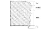
- Shear workability (secondary shear surface evaluation) The shear workability of the hot-rolled steel sheets was evaluated by a punching test. Three punched holes were prepared for each example with a hole diameter of 10 mm, a clearance of 10%, and a punching speed of 3 m/s. Next, the cross section perpendicular to the rolling direction and the cross section parallel to the rolling direction of the punched holes were embedded in resin, and the cross-sectional shape was photographed with a scanning electron microscope. In the obtained observation photograph, the sheared end surface as shown in FIG. 1 or FIG. 2 can be observed. Note that FIG. 1 is an example of a sheared end surface of a hot-rolled steel sheet according to an example of the present invention, and FIG.
- FIG. 2 is an example of a sheared end surface of a hot-rolled steel sheet according to a comparative example.
- the sheared end surface is a sag-shear surface-fracture surface-burr.
- the sheared end surface is a sag-shear surface-fracture surface-shear surface-fracture surface-burr.
- the sag is a region of a smooth R-shaped surface
- the sheared surface is a region of the punched end surface separated by shear deformation
- the fractured surface is a region of the punched end surface separated by a crack generated near the cutting edge
- the burr is a surface having a protrusion protruding from the lower surface of the hot-rolled steel sheet.
- Chemical conversion treatability A sample of 150 mm x 70 mm was taken from the hot-rolled steel sheet after pickling, and was subjected to chemical conversion treatment using a chemical conversion treatment solution (PB-SX35) manufactured by Nihon Parkerizing Co., Ltd. Three locations (center and both ends) along the length of the test piece were observed at 1000 times magnification using a scanning electron microscope (SEM) to observe the degree of adhesion of the crystal grains of the zinc phosphate film.
- the pickling conditions were the same as those for the pickling treatment described above.
- the resistance to internal bending cracks was investigated.
- the value obtained by dividing the average value of the minimum bending radius of the L axis and the C axis by the plate thickness was taken as the limit bending R/t, which was used as an index value of resistance to internal bending cracks.
- the hot-rolled steel sheets according to the examples of the present invention have high strength and a critical thickness reduction rate at break, while also having excellent ductility, shear workability, chemical conversion treatability, and resistance to internal bending cracking.
- the heat-rolled steel sheets according to the comparative examples are deteriorated in at least one of the above characteristics.
- the hot-rolled steel sheet according to the present invention is suitable as an industrial material used for automobile parts, machine structural parts, and further building parts.
Landscapes
- Chemical & Material Sciences (AREA)
- Engineering & Computer Science (AREA)
- Materials Engineering (AREA)
- Mechanical Engineering (AREA)
- Metallurgy (AREA)
- Organic Chemistry (AREA)
- Physics & Mathematics (AREA)
- Thermal Sciences (AREA)
- Crystallography & Structural Chemistry (AREA)
- Heat Treatment Of Sheet Steel (AREA)
Abstract
この熱延鋼板は、所望の化学組成を有し、板厚方向の表面から1/4位置における金属組織が、面積%で、残留オーステナイトが3.0%未満であり、フェライトが15.0%以上、60.0%未満であり、パーライトが5.0%未満であり、E値が10.7以上であり、I値が1.020以上であり、CS値が-8.0×105~8.0×105であり、Mn濃度の標準偏差が0.60質量%以下であり、前記表面において、Ni濃度が0.2質量%以上である領域の面積率が10.0%以上であり、O濃度が3.0質量%以上である領域の面積率が3.0~50.0%であり、酸化物の球相当直径の最大値が5.00μm以下であり、引張強さが980MPa以上である。
Description
本発明は、熱延鋼板に関する。
本願は、2022年10月12日に、日本に出願された特願2022-163955号に基づき優先権を主張し、その内容をここに援用する。
本願は、2022年10月12日に、日本に出願された特願2022-163955号に基づき優先権を主張し、その内容をここに援用する。
近年、地球環境保護の観点から、多くの分野において炭酸ガス排出量の削減が取り組まれている。自動車メーカーにおいても低燃費化を目的とした車体軽量化の技術開発が盛んに行われている。しかし、乗員の安全確保のために耐衝突特性の向上にも重点が置かれるため、車体軽量化は容易ではない。
車体軽量化と耐衝突特性とを両立させるべく、高強度鋼板を用いて部材を薄肉化することが検討されている。このため、高い強度と優れた成形性とを兼備する鋼板が強く望まれており、これらの要求に応えるべく、幾つかの技術が従来から提案されている。
自動車部材には様々な加工様式があるため、要求される成形性は適用される部材により異なる。その中でも、限界破断板厚減少率および延性は成形性の重要な指標として位置付けられている。限界破断板厚減少率とは、破断前の引張試験片の板厚と、破断後の引張試験片の板厚の最小値とから求められる値である。限界破断板厚減少率が低い場合、プレス成形中の引張ひずみが付与された際に早期に破断し易くなるため、好ましくない。
自動車部材はプレス成形によって成形されるが、そのプレス成形のブランク板は生産性が高いせん断加工によって製造されることが多い。せん断加工によって製造されるブランク板では、せん断加工後の端面精度に優れる必要がある。
例えば、せん断加工後の端面(せん断端面)の様相が、せん断面-破断面-せん断面となる2次せん断面が発生すると、せん断端面の精度が著しく劣化する。
また、鋼板の強度が高くなるほど、曲げ加工時に曲げ内側から亀裂が生じやすくなることが知られている(以下、曲げ加工時に曲げ内側に生じる割れを曲げ内割れと呼称する)。曲げ内割れのメカニズムは以下のように推定される。曲げ加工時には曲げ内側に圧縮の応力が生じる。最初は曲げ内側全体が均一に変形しながら加工が進むが、加工量が大きくなると均一な変形のみで変形を担えなくなり、局所にひずみが集中することで変形が進む(せん断変形帯の発生)。このせん断変形帯が更に成長することで曲げ内側表面からせん断帯に沿った亀裂が発生し、成長する。鋼板の高強度化に伴い曲げ内割れが発生しやすくなる理由は、高強度化に伴う加工硬化能の低下により、均一な変形が進みにくくなり、変形の偏りが生じやすくなることで、加工早期に(または緩い加工条件で)せん断変形帯が生じるためと推定される。上述の通り自動車部材には様々な加工様式があり、鋼板が曲げ加工を施される場合も多いため、曲げ内割れが生じることは好ましくない。
また、鋼板には、耐食性向上等を目的として表面に化成処理皮膜が形成される場合がある。高強度化のために鋼板中のSi含有量を高めると、鋼板表層にSiを含む酸化物が生成、残存しやすくなり、これにより鋼板の化成処理性が劣化し、化成処理皮膜が十分に形成されない場合がある。
例えば、特許文献1には、板厚中央部におけるMn偏析度およびP偏析度を制御した、プレス加工後の表面性状に優れた冷延鋼板の素材となる熱延鋼板が開示されている。
J. Webel, J. Gola, D. Britz, F. Mucklich, Materials Characterization 144 (2018) 584-596
D. L. Naik, H. U. Sajid, R. Kiran, Metals 2019, 9, 546
K. Zuiderveld, Contrast Limited Adaptive Histogram Equalization, Chapter VIII.5, Graphics Gems IV. P.S. Heckbert (Eds.), Cambridge, MA, Academic Press, 1994, pp. 474-485
しかしながら、特許文献1では、熱延鋼板の限界破断板厚減少率、曲げ内割れおよび化成処理性について考慮されていない。
本発明は、上述の実情に鑑みてなされたものであり、高い強度および限界破断板厚減少率を有し、且つ、優れた延性、せん断加工性および化成処理性を有するとともに、曲げ内割れの発生が抑制された、すなわち耐曲げ内割れ性に優れた熱延鋼板を提供することを目的とする。
本発明の要旨は、以下の通りである。
(1)本発明の一態様に係る熱延鋼板は、化学組成が、質量%で、
C :0.050~0.250%、
Si:0.05~3.00%、
Mn:1.00~4.00%、
Ni:0.02~2.00%、
sol.Al:0.001~2.000%、
P :0.100%以下、
S :0.0300%以下、
N :0.1000%以下、
O :0.0100%以下、
Ti:0~0.500%、
Nb:0~0.500%、
V :0~0.500%、
Cu:0~2.00%、
Cr:0~2.00%、
Mo:0~1.00%、
B :0~0.0100%、
Ca:0~0.0200%、
Mg:0~0.0200%、
REM:0~0.1000%、
Bi:0~0.0200%、
As:0~0.100%、
Zr:0~1.00%、
Co:0~1.00%、
Zn:0~1.00%、
W :0~1.00%、および
Sn:0~0.05%を含有し、
残部がFeおよび不純物からなり、
下記式(A)および(B)を満たし、
板厚方向の表面から1/4位置における金属組織が、
面積%で、
残留オーステナイトが3.0%未満であり、
フェライトが15.0%以上、60.0%未満であり、
パーライトが5.0%未満であり、
グレーレベル共起行列法により、前記金属組織のSEM画像を解析することによって得られる、下記式(1)で示されるEntropy値が10.7以上であり、
下記式(2)で示されるInverse difference normalized値が1.020以上であり、
下記式(3)で示されるCluster Shade値が-8.0×10⁵~8.0×10⁵であり、
Mn濃度の標準偏差が0.60質量%以下であり、
前記表面において、
Ni濃度が0.2質量%以上である領域の面積率が10.0%以上であり、
O濃度が3.0質量%以上である領域の面積率が3.0~50.0%であり、
酸化物の球相当直径の最大値が5.00μm以下であり、
引張強さが980MPa以上である。
0.060%≦Ti+Nb+V≦0.500% …(A)
Zr+Co+Zn+W≦1.00% …(B)
ただし、前記式(A)および(B)中の各元素記号は、当該元素の質量%での含有量を示し、当該元素を含有しない場合は0%を代入する。
ここで、下記式(1)~(5)中のP(i,j)はグレーレベル共起行列であり、下記式(2)中のLは前記SEM画像の取り得るグレースケールのレベル数であり、下記式(2)および(3)中のiおよびjは1~前記Lの自然数であり、下記式(3)中のμxおよびμyはそれぞれ下記式(4)および(5)で示される。


(2)上記(1)に記載の熱延鋼板は、前記化学組成が、質量%で、
Ti:0.001~0.500%、
Nb:0.001~0.500%、
V :0.001~0.500%、
Cu:0.01~2.00%、
Cr:0.01~2.00%、
Mo:0.01~1.00%、
B :0.0001~0.0100%、
Ca:0.0005~0.0200%、
Mg:0.0005~0.0200%、
REM:0.0005~0.1000%、
Bi:0.0005~0.0200%、
As:0.001~0.100%、
Zr:0.01~1.00%、
Co:0.01~1.00%、
Zn:0.01~1.00%、
W :0.01~1.00%、および
Sn:0.01~0.05%
からなる群から選択される1種または2種以上を含有してもよい。
(1)本発明の一態様に係る熱延鋼板は、化学組成が、質量%で、
C :0.050~0.250%、
Si:0.05~3.00%、
Mn:1.00~4.00%、
Ni:0.02~2.00%、
sol.Al:0.001~2.000%、
P :0.100%以下、
S :0.0300%以下、
N :0.1000%以下、
O :0.0100%以下、
Ti:0~0.500%、
Nb:0~0.500%、
V :0~0.500%、
Cu:0~2.00%、
Cr:0~2.00%、
Mo:0~1.00%、
B :0~0.0100%、
Ca:0~0.0200%、
Mg:0~0.0200%、
REM:0~0.1000%、
Bi:0~0.0200%、
As:0~0.100%、
Zr:0~1.00%、
Co:0~1.00%、
Zn:0~1.00%、
W :0~1.00%、および
Sn:0~0.05%を含有し、
残部がFeおよび不純物からなり、
下記式(A)および(B)を満たし、
板厚方向の表面から1/4位置における金属組織が、
面積%で、
残留オーステナイトが3.0%未満であり、
フェライトが15.0%以上、60.0%未満であり、
パーライトが5.0%未満であり、
グレーレベル共起行列法により、前記金属組織のSEM画像を解析することによって得られる、下記式(1)で示されるEntropy値が10.7以上であり、
下記式(2)で示されるInverse difference normalized値が1.020以上であり、
下記式(3)で示されるCluster Shade値が-8.0×10⁵~8.0×10⁵であり、
Mn濃度の標準偏差が0.60質量%以下であり、
前記表面において、
Ni濃度が0.2質量%以上である領域の面積率が10.0%以上であり、
O濃度が3.0質量%以上である領域の面積率が3.0~50.0%であり、
酸化物の球相当直径の最大値が5.00μm以下であり、
引張強さが980MPa以上である。
0.060%≦Ti+Nb+V≦0.500% …(A)
Zr+Co+Zn+W≦1.00% …(B)
ただし、前記式(A)および(B)中の各元素記号は、当該元素の質量%での含有量を示し、当該元素を含有しない場合は0%を代入する。
ここで、下記式(1)~(5)中のP(i,j)はグレーレベル共起行列であり、下記式(2)中のLは前記SEM画像の取り得るグレースケールのレベル数であり、下記式(2)および(3)中のiおよびjは1~前記Lの自然数であり、下記式(3)中のμxおよびμyはそれぞれ下記式(4)および(5)で示される。
Ti:0.001~0.500%、
Nb:0.001~0.500%、
V :0.001~0.500%、
Cu:0.01~2.00%、
Cr:0.01~2.00%、
Mo:0.01~1.00%、
B :0.0001~0.0100%、
Ca:0.0005~0.0200%、
Mg:0.0005~0.0200%、
REM:0.0005~0.1000%、
Bi:0.0005~0.0200%、
As:0.001~0.100%、
Zr:0.01~1.00%、
Co:0.01~1.00%、
Zn:0.01~1.00%、
W :0.01~1.00%、および
Sn:0.01~0.05%
からなる群から選択される1種または2種以上を含有してもよい。
本発明に係る上記態様によれば、高い強度および限界破断板厚減少率を有し、且つ、優れた延性、せん断加工性、化成処理性および耐曲げ内割れ性を有する熱延鋼板を得ることができる。
本発明の上記態様に係る熱延鋼板は、自動車部材、機械構造部材さらには建築部材に用いられる工業用素材として好適である。
本発明の上記態様に係る熱延鋼板は、自動車部材、機械構造部材さらには建築部材に用いられる工業用素材として好適である。
本実施形態に係る熱延鋼板の化学組成および金属組織について、以下により具体的に説明する。ただし、本発明は本実施形態に開示の構成のみに制限されることなく、本発明の趣旨を逸脱しない範囲で種々の変更が可能である。
以下に「~」を挟んで記載する数値限定範囲には、下限値および上限値がその範囲に含まれる。「未満」または「超」と示す数値には、その値が数値範囲に含まれない。以下の説明において、化学組成に関する%は特に指定しない限り質量%である。
化学組成
本実施形態に係る熱延鋼板の化学組成は、質量%で、C:0.050~0.250%、Si:0.05~3.00%、Mn:1.00~4.00%、Ni:0.02~2.00%、sol.Al:0.001~2.000%、P:0.100%以下、S:0.0300%以下、N:0.1000%以下、O:0.0100%以下、並びに、残部:Feおよび不純物を含み、式(A)(0.060%≦Ti+Nb+V≦0.500%)を満たす。
以下に各元素について詳細に説明する。
本実施形態に係る熱延鋼板の化学組成は、質量%で、C:0.050~0.250%、Si:0.05~3.00%、Mn:1.00~4.00%、Ni:0.02~2.00%、sol.Al:0.001~2.000%、P:0.100%以下、S:0.0300%以下、N:0.1000%以下、O:0.0100%以下、並びに、残部:Feおよび不純物を含み、式(A)(0.060%≦Ti+Nb+V≦0.500%)を満たす。
以下に各元素について詳細に説明する。
C:0.050~0.250%
Cは、硬質相の面積率を上昇させるとともに、Ti、Nb、V等の析出強化元素と結合することで、フェライトの強度を上昇させる。C含有量が0.050%未満では、所望の強度を得ることができない。したがって、C含有量は0.050%以上とする。C含有量は、好ましくは0.060%以上、より好ましくは0.070%以上、より一層好ましくは0.080%以上または0.090%以上である。
一方、C含有量が0.250%超では、フェライトの面積率が低下することで、熱延鋼板の延性が低下する。したがって、C含有量は0.250%以下とする。C含有量は好ましくは0.200%以下、0.150%以下または0.120%以下である。
Cは、硬質相の面積率を上昇させるとともに、Ti、Nb、V等の析出強化元素と結合することで、フェライトの強度を上昇させる。C含有量が0.050%未満では、所望の強度を得ることができない。したがって、C含有量は0.050%以上とする。C含有量は、好ましくは0.060%以上、より好ましくは0.070%以上、より一層好ましくは0.080%以上または0.090%以上である。
一方、C含有量が0.250%超では、フェライトの面積率が低下することで、熱延鋼板の延性が低下する。したがって、C含有量は0.250%以下とする。C含有量は好ましくは0.200%以下、0.150%以下または0.120%以下である。
Si:0.05~3.00%
Siは、フェライトの生成を促進して熱延鋼板の延性を向上させる作用と、フェライトを固溶強化して熱延鋼板の強度を上昇させる作用とを有する。また、Siは脱酸により鋼を健全化する(鋼にブローホールなどの欠陥が生じることを抑制する)作用を有する。Si含有量が0.05%未満では、上記作用による効果を得ることができない。したがって、Si含有量は0.05%以上とする。Si含有量は、好ましくは0.50%以上、より好ましくは0.80%以上、1.00%以上、1.20%以上または1.40%以上である。
しかし、Si含有量が3.00%超では、熱延鋼板の表面性状および化成処理性、さらには延性および溶接性が著しく劣化するとともに、A3変態点が著しく上昇する。これにより、安定して熱間圧延を行うことが困難になる。また、フェライトが過剰に生成し易くなり、熱延鋼板の強度が低下することに加え、冷却後にオーステナイトが残留し易くなり、限界破断板厚減少率が低下する。したがって、Si含有量は3.00%以下とする。Si含有量は、好ましくは2.70%以下、より好ましくは2.50%以下、2.20%以下、2.00%以下または1.80%以下である。
Mn:1.00~4.00%
Mnは、フェライト変態を抑制して熱延鋼板の強度を高める作用を有する。Mn含有量が1.00%未満では、所望の強度を得ることができない。したがって、Mn含有量は1.00%以上とする。Mn含有量は、好ましくは1.30%以上であり、より好ましくは1.50%以上または1.80%以上である。
一方、Mn含有量が4.00%超では、Mnの偏析に起因して、硬質相の形態が周期的なバンド状となり、所望のせん断加工性を得ることが困難となる。したがって、Mn含有量は4.00%以下とする。Mn含有量は、好ましくは3.70%以下または3.50%以下、より好ましくは3.20%以下、3.00%以下または2.60%以下である。
Mnは、フェライト変態を抑制して熱延鋼板の強度を高める作用を有する。Mn含有量が1.00%未満では、所望の強度を得ることができない。したがって、Mn含有量は1.00%以上とする。Mn含有量は、好ましくは1.30%以上であり、より好ましくは1.50%以上または1.80%以上である。
一方、Mn含有量が4.00%超では、Mnの偏析に起因して、硬質相の形態が周期的なバンド状となり、所望のせん断加工性を得ることが困難となる。したがって、Mn含有量は4.00%以下とする。Mn含有量は、好ましくは3.70%以下または3.50%以下、より好ましくは3.20%以下、3.00%以下または2.60%以下である。
Ni:0.02~2.00%
Niは、熱延鋼板の焼入性を高める作用を有する。また、Niは、粗圧延時にスケールの成長と共に鋼板表層に濃化することで、化成処理皮膜の析出核となり、スケがなく密着性の良い化成処理皮膜の形成を促進する。これにより、熱延鋼板の化成処理性を高める作用を有する。Ni含有量が0.02%未満であると、熱延鋼板の化成処理性が劣化する。そのため、Ni含有量は0.02%以上とする。Ni含有量は、好ましくは0.04%以上であり、より好ましくは0.06%以上であり、より一層好ましくは0.08%以上である。
一方、Ni含有量を2.00%超としても、上記効果は飽和するととともに合金コストが増大するため、好ましくない。そのため、Ni含有量は2.00%以下とする。Ni含有量は、好ましくは1.80%以下であり、より好ましくは1.60%以下である。
Ti:0~0.500%
Nb:0~0.500%
V:0~0.500%
0.060%≦Ti+Nb+V≦0.500% …(A)
ただし、前記式(A)中の各元素記号は、当該元素の質量%での含有量を示し、当該元素を含有しない場合は0%を代入する。
Ti、NbおよびVは、炭化物および窒化物として鋼中に微細析出し、析出強化により鋼の強度を向上させる元素である。Ti、NbおよびVの合計の含有量が0.060%未満であると、これらの効果を得ることができない。そのため、Ti、NbおよびVの合計の含有量を0.060%以上とする。すなわち、前記式(A)の中辺の値を0.060%以上とする。なお、Ti、NbおよびVの全てが含有されている必要はなく、いずれか1種でも含まれていればよく、その合計の含有量が0.060%以上であればよい。そのため、Ti、NbおよびVの含有量の下限はそれぞれ0%である。Ti、NbおよびVの含有量の下限は、それぞれ0.001%、0.010%、0.030%または0.050%としてもよい。Ti、NbおよびVの合計の含有量は、好ましくは0.080%以上、より好ましくは0.100%以上である。
一方、Ti、NbおよびVのいずれか1種の含有量が0.500%を超えると、あるいは、Ti、NbおよびVの合計の含有量が0.500%を超えると、熱延鋼板の加工性が劣化する。そのため、Ti、NbおよびVのそれぞれの含有量を0.500%以下とし、且つ、Ti、NbおよびVの合計の含有量を0.500%以下とする。すなわち、前記式(A)の中辺の値を0.500%以下とする。Ti、NbおよびVのそれぞれの含有量は、好ましくは0.400%以下または0.300%以下であり、より好ましくは0.250%以下であり、より一層好ましくは0.200%以下または0.100%以下である。
sol.Al:0.001~2.000%
Alは、Siと同様に、鋼を脱酸して鋼を健全化する作用を有するとともに、フェライトの生成を促進し、熱延鋼板の延性を高める作用を有する。sol.Al含有量が0.001%未満では上記作用による効果を得ることができない。したがって、sol.Al含有量は、0.001%以上とする。sol.Al含有量は、好ましくは0.010%以上、0.030%以上または0.050%以上であり、より好ましくは0.080%以上、0.100%以上または0.150%以上である。
一方、sol.Al含有量が2.000%超では、上記効果が飽和するとともに経済的に好ましくない。そのため、sol.Al含有量は2.000%以下とする。sol.Al含有量は、好ましくは1.700%以下または1.500%以下、より好ましくは1.300%以下、より一層好ましくは1.000%以下である。
なお、sol.Alとは酸可溶性Alを意味し、固溶状態で鋼中に存在する固溶Alのことを示す。
P:0.100%以下
Pは、固溶強化により熱延鋼板の強度を高める作用を有する元素でもある。P含有量は0%としてもよく、Pを積極的に含有させてもよい。しかし、Pは偏析し易い元素であり、P含有量が0.100%を超えると、粒界偏析に起因する熱延鋼板の延性および限界破断板厚減少率の低下が顕著となる。したがって、P含有量は、0.100%以下とする。P含有量は、好ましくは0.050%以下、0.030%以下、0.020%以下または0.015%以下である。
P含有量は、精錬コストの観点から、0.001%以上、0.003%以上または0.005%以上としてもよい。
Pは、固溶強化により熱延鋼板の強度を高める作用を有する元素でもある。P含有量は0%としてもよく、Pを積極的に含有させてもよい。しかし、Pは偏析し易い元素であり、P含有量が0.100%を超えると、粒界偏析に起因する熱延鋼板の延性および限界破断板厚減少率の低下が顕著となる。したがって、P含有量は、0.100%以下とする。P含有量は、好ましくは0.050%以下、0.030%以下、0.020%以下または0.015%以下である。
P含有量は、精錬コストの観点から、0.001%以上、0.003%以上または0.005%以上としてもよい。
S:0.0300%以下
Sは、鋼中に硫化物系介在物を形成して熱延鋼板の延性および限界破断板厚減少率を低下させる。S含有量が0.0300%を超えると、熱延鋼板の延性および限界破断板厚減少率が著しく低下する。したがって、S含有量は0.0300%以下とする。S含有量は、好ましくは0.0100%以下、0.0070%以下または0.0050%以下である。
S含有量は0%としてもよいが、精錬コストの観点から、0.0001%以上、0.0005%以上、0.0010%以上または0.0020%以上としてもよい。
Sは、鋼中に硫化物系介在物を形成して熱延鋼板の延性および限界破断板厚減少率を低下させる。S含有量が0.0300%を超えると、熱延鋼板の延性および限界破断板厚減少率が著しく低下する。したがって、S含有量は0.0300%以下とする。S含有量は、好ましくは0.0100%以下、0.0070%以下または0.0050%以下である。
S含有量は0%としてもよいが、精錬コストの観点から、0.0001%以上、0.0005%以上、0.0010%以上または0.0020%以上としてもよい。
N:0.1000%以下
Nは、熱延鋼板の延性および限界破断板厚減少率を低下させる作用を有する。N含有量が0.1000%超では、熱延鋼板の延性および限界破断板厚減少率が著しく低下する。したがって、N含有量は0.1000%以下とする。N含有量は、好ましくは0.0800%以下であり、より好ましくは0.0700%以下または0.0300%以下であり、より一層好ましくは0.0150%以下または0.0100%以下である。
N含有量は0%としてもよいが、Ti、NbおよびVの1種または2種以上を含有させて金属組織をより微細化する場合には、炭窒化物の析出を促進させるために0.0010%以上とすることが好ましく、0.0015%以上または0.0020%以上とすることがより好ましい。
O:0.0100%以下
Oは、鋼中に多く含まれると破壊の起点となる粗大な酸化物を形成し、脆性破壊や水素誘起割れを引き起こす。そのため、O含有量は0.0100%以下とする。O含有量は、好ましくは0.0080%以下、より好ましくは0.0050%以下または0.0030%以下である。
O含有量は0%としてもよいが、溶鋼の脱酸時に微細な酸化物を多数分散させるために、0.0005%以上、または0.0010%以上としてもよい。
Oは、鋼中に多く含まれると破壊の起点となる粗大な酸化物を形成し、脆性破壊や水素誘起割れを引き起こす。そのため、O含有量は0.0100%以下とする。O含有量は、好ましくは0.0080%以下、より好ましくは0.0050%以下または0.0030%以下である。
O含有量は0%としてもよいが、溶鋼の脱酸時に微細な酸化物を多数分散させるために、0.0005%以上、または0.0010%以上としてもよい。
本実施形態に係る熱延鋼板の化学組成の残部は、Feおよび不純物であってもよい。本実施形態において、不純物とは、原料としての鉱石、スクラップ、または製造環境等から混入されるもの、および/または本実施形態に係る熱延鋼板に悪影響を与えない範囲で許容されるものを意味する。
本実施形態に係る熱延鋼板は、Feの一部に代えて、下記元素を任意元素として含有してもよい。これらの任意元素を含有させない場合の含有量の下限は0%である。以下、任意元素について詳細に説明する。
Cu:0.01~2.00%
Cr:0.01~2.00%
Mo:0.01~1.00%
B:0.0001~0.0100%
Cu、Cr、MoおよびBは、いずれも、熱延鋼板の焼入性を高める作用を有する。また、CuおよびMoは鋼中に炭化物として析出して熱延鋼板の強度を高める作用を有する。さらに、Niは、Cuを含有させる場合においては、Cuに起因するスラブの粒界割れを効果的に抑制する作用を有する。したがって、これらの元素の1種または2種以上を含有させてもよい。
Cr:0.01~2.00%
Mo:0.01~1.00%
B:0.0001~0.0100%
Cu、Cr、MoおよびBは、いずれも、熱延鋼板の焼入性を高める作用を有する。また、CuおよびMoは鋼中に炭化物として析出して熱延鋼板の強度を高める作用を有する。さらに、Niは、Cuを含有させる場合においては、Cuに起因するスラブの粒界割れを効果的に抑制する作用を有する。したがって、これらの元素の1種または2種以上を含有させてもよい。
上述したようにCuは、熱延鋼板の焼入れ性を高める作用および低温で鋼中に炭化物として析出して熱延鋼板の強度を高める作用を有する。上記作用による効果をより確実に得るためには、Cu含有量は0.01%以上とすることが好ましく、0.05%以上とすることがより好ましい。しかし、Cu含有量が2.00%超では、スラブの粒界割れが生じる場合がある。したがって、Cu含有量は2.00%以下とする。Cu含有量は、好ましくは1.50%以下、より好ましくは1.00%以下、0.70%以下または0.50%以下である。
上述したようにCrは、熱延鋼板の焼入性を高める作用を有する。上記作用による効果をより確実に得るためには、Cr含有量を0.01%以上とすることが好ましく、0.05%以上とすることがより好ましい。しかし、Cr含有量が2.00%超では、熱延鋼板の化成処理性が著しく低下する。したがって、Cr含有量は2.00%以下とする。Cr含有量は、好ましくは1.50%以下、より好ましくは1.00%以下、0.70%以下または0.50%以下である。
上述したようにMoは、熱延鋼板の焼入性を高める作用および鋼中に炭化物として析出して熱延鋼板の強度を高める作用を有する。上記作用による効果をより確実に得るためには、Mo含有量を0.01%以上とすることが好ましく、0.02%以上とすることがより好ましい。しかし、Mo含有量を1.00%超としても上記作用による効果は飽和して経済的に好ましくない。したがって、Mo含有量は1.00%以下とする。Mo含有量は、好ましくは0.50%以下、より好ましくは0.20%以下または0.10%以下である。
上述したようにBは、熱延鋼板の焼入れ性を高める作用を有する。この作用による効果をより確実に得るためには、B含有量を0.0001%以上とすることが好ましく、0.0002%以上とすることがより好ましい。しかし、B含有量が0.0100%超では、熱延鋼板の成形性が著しく低下するため、B含有量は0.0100%以下とする。B含有量は、0.0050%以下または0.0025%以下とすることが好ましい。
Ca:0.0005~0.0200%
Mg:0.0005~0.0200%
REM:0.0005~0.1000%
Bi:0.0005~0.0200%
Ca、MgおよびREMは、いずれも、鋼中の介在物の形状を好ましい形状に調整することにより、熱延鋼板の延性を高める作用を有する。また、Biは、凝固組織を微細化することにより、熱延鋼板の延性を高める作用を有する。したがって、これらの元素の1種または2種以上を含有させてもよい。上記作用による効果をより確実に得るためには、Ca、Mg、REMおよびBiのいずれか1種以上の含有量を0.0005%以上とすることが好ましい。しかし、Ca含有量またはMg含有量が0.0200%を超えると、あるいはREM含有量が0.1000%を超えると、鋼中に介在物が過剰に生成され、却って熱延鋼板の延性を低下させる場合がある。また、Bi含有量を0.0200%超としても、上記作用による効果は飽和してしまい、経済的に好ましくない。したがって、Ca含有量およびMg含有量を0.0200%以下、REM含有量を0.1000%以下、並びにBi含有量を0.0200%以下とする。Ca含有量、Mg含有量およびBi含有量は、好ましくは0.0100%以下であり、より好ましくは0.0070%以下または0.0040%以下である。REM含有量は、好ましくは0.0070%以下または0.0040%以下である。
ここで、REMは、Sc、Yおよびランタノイドからなる合計17元素を指し、上記REMの含有量は、これらの元素の合計含有量を指す。ランタノイドの場合、工業的にはミッシュメタルの形で添加される。
As:0.001~0.100%
Asは、オーステナイト単相化温度を低下させることにより、旧オーステナイト粒を細粒化させて、熱延鋼板の延性の向上に寄与する。この効果を確実に得るためには、As含有量を0.001%以上とすることが好ましい。一方、Asを多量に含有させても上記効果は飽和するため、As含有量は0.100%以下とする。
Asは、オーステナイト単相化温度を低下させることにより、旧オーステナイト粒を細粒化させて、熱延鋼板の延性の向上に寄与する。この効果を確実に得るためには、As含有量を0.001%以上とすることが好ましい。一方、Asを多量に含有させても上記効果は飽和するため、As含有量は0.100%以下とする。
Zr:0.01~1.00%
Co:0.01~1.00%
Zn:0.01~1.00%
W :0.01~1.00%
Zr+Co+Zn+W≦1.00% …(B)
Sn:0.01~0.05%
前記式(B)中の各元素記号は、当該元素の質量%での含有量を示し、当該元素を含有しない場合は0%を代入する。
Zr、Co、ZnおよびWについて、本発明者らは、これらの元素を合計で1.00%以下含有させても、本実施形態に係る熱延鋼板の効果は損なわれないことを確認している。そのため、Zr、Co、ZnおよびWのうち1種または2種以上を合計で1.00%以下含有させてもよい。すなわち、前記式(B)の左辺の値を1.00%以下としてもよく、0.50%以下、0.10%以下または0.05%以下としてもよい。Zr、Co、Zn、WおよびSnの各含有量は、それぞれ0.50%以下、0.10%以下または0.05%以下としてもよい。Zr、Co、ZnおよびWは含有させなくてもよいため、それぞれの含有量は0%であってもよい。鋼板を固溶強化させて強度を向上させるため、Zr、Co、ZnおよびWの含有量はそれぞれ0.01%以上であってもよい。
また、本発明者らは、Snを少量含有させても本実施形態に係る熱延鋼板の効果は損なわれないことを確認している。しかし、Snを多量に含有させると熱間圧延時に疵が発生する場合があるため、Sn含有量は0.05%以下とする。Snは含有させなくてもよいため、Sn含有量は0%であってもよい。熱延鋼板の耐食性を高めるため、Sn含有量は0.01%以上としてもよい。
上述した熱延鋼板の化学組成は、一般的な分析方法によって測定すればよい。例えば、ICP-AES(Inductively Coupled Plasma-Atomic Emission Spectrometry)を用いて測定すればよい。なお、sol.Alは、試料を酸で加熱分解した後の濾液を用いてICP-AESによって測定すればよい。CおよびSは燃焼-赤外線吸収法を用い、Nは不活性ガス融解-熱伝導度法を用い、Oは不活性ガス融解-非分散型赤外線吸収法を用いて測定すればよい。
熱延鋼板が表面にめっき層を備える場合は、必要に応じて、機械研削等によりめっき層を除去してから、化学組成の分析を行ってもよい。
熱延鋼板が表面にめっき層を備える場合は、必要に応じて、機械研削等によりめっき層を除去してから、化学組成の分析を行ってもよい。
熱延鋼板の金属組織
次に、本実施形態に係る熱延鋼板の金属組織について説明する。
本実施形態に係る熱延鋼板は、板厚方向の表面から1/4位置における金属組織が、面積%で、残留オーステナイトが3.0%未満であり、フェライトが15.0%以上、60.0%未満であり、パーライトが5.0%未満であり、グレーレベル共起行列法により、前記金属組織のSEM画像を解析することによって得られる、下記式(1)で示されるEntropy値が10.7以上であり、下記式(2)で示されるInverse difference normalized値が1.020以上であり、下記式(3)で示されるCluster Shade値が-8.0×10⁵~8.0×10⁵であり、Mn濃度の標準偏差が0.60質量%以下であり、表面において、Ni濃度が0.2質量%以上である領域の面積率が10.0%以上であり、O濃度が3.0質量%以上である領域の面積率が3.0~50.0%であり、酸化物の球相当直径の最大値が5.00μm以下である。
なお、本実施形態では、板厚方向の表面から1/4位置の領域における金属組織の組織分率、Entropy値、Inverse difference normalized値、Cluster Shade値、およびMn濃度の標準偏差を規定する。その理由は、この位置における金属組織が、鋼板の代表的な金属組織を示すからである。
また、ここでいう「表面」とは、熱延鋼板がめっき層を備える場合においてはめっき層と鋼板との界面のことをいい、「表面から1/4深さ位置」とは、熱延鋼板の表面から、板厚方向に、板厚の1/4の深さである位置のことをいう。
また、ここでいう「表面」とは、熱延鋼板がめっき層を備える場合においてはめっき層と鋼板との界面のことをいい、「表面から1/4深さ位置」とは、熱延鋼板の表面から、板厚方向に、板厚の1/4の深さである位置のことをいう。
残留オーステナイトの面積率:3.0%未満
残留オーステナイトは室温でも面心立方格子として存在する金属組織である。残留オーステナイトは、変態誘起塑性(TRIP)により熱延鋼板の延性を高める作用を有する。一方、残留オーステナイトは、せん断加工中には高炭素のマルテンサイトに変態するため、変形中のき裂発生の起点となり、限界破断板厚減少率低下の原因となる。残留オーステナイトの面積率が3.0%以上では、上記作用が顕在化し、熱延鋼板の限界破断板厚減少率が低下する。そのため、残留オーステナイトの面積率は3.0%未満とする。残留オーステナイトの面積率は、好ましくは1.5%未満、より好ましくは1.0%未満である。
残留オーステナイトは少ない程好ましいため、残留オーステナイトの面積率は0%であってもよい。
残留オーステナイトの面積率の測定方法には、X線回折、EBSP(電子後方散乱回折像、Electron Back Scattering Diffraction Pattern)解析、磁気測定による方法などがある。本実施形態では、残留オーステナイトの面積率はX線回折により測定する。
本実施形態におけるX線回折による残留オーステナイト面積率の測定では、まず、熱延鋼板の板厚方向の表面から1/4位置の断面において、圧延方向の任意の位置で1mm以上、圧延方向および板厚方向に直行する方向における中央を中心に1mm以上の領域における金属組織が観察できるようにサンプルを採取し、板厚方向の表面から1/4位置が表面となるように、機械研磨および化学研磨により減厚する。上記サンプルを、X線回折装置(例えばRigaku製RINT-2500、Co-Kα線)を用いて、α(110)、α(200)、α(211)、γ(111)、γ(200)、γ(220)の計6ピークの積分強度を求める。次に、前記積分強度から強度平均法を用いて残留オーステナイトの体積率を算出する。得られた残留オーステナイトの体積率を、残留オーステナイトの面積率とみなす。
フェライトの面積率:15.0%以上、60.0%未満
フェライトは比較的高温でfccがbccに変態したときに生成する組織である。フェライトは加工硬化率が高いため、熱延鋼板の強度-延性バランスを高める作用がある。上記の作用を得るため、フェライトの面積率は15.0%以上とする。好ましくは20.0%以上であり、より好ましくは25.0%以上であり、より一層好ましくは30.0%以上である。
一方、フェライトは強度が低いため、面積率が過剰であると所望の強度を得ることができない。このため、フェライト面積率は60.0%未満とする。好ましくは50.0%以下であり、より好ましくは45.0%以下である。
フェライトは比較的高温でfccがbccに変態したときに生成する組織である。フェライトは加工硬化率が高いため、熱延鋼板の強度-延性バランスを高める作用がある。上記の作用を得るため、フェライトの面積率は15.0%以上とする。好ましくは20.0%以上であり、より好ましくは25.0%以上であり、より一層好ましくは30.0%以上である。
一方、フェライトは強度が低いため、面積率が過剰であると所望の強度を得ることができない。このため、フェライト面積率は60.0%未満とする。好ましくは50.0%以下であり、より好ましくは45.0%以下である。
パーライトの面積率:5.0%未満
パーライトは、フェライト同士の間にセメンタイトが層状に析出したラメラ状の金属組織であり、またベイナイトやマルテンサイトと比較すると軟質な金属組織である。パーライトの面積率が5.0%以上であると、パーライトに含まれるセメンタイトに炭素が消費され、残部組織であるマルテンサイトおよびベイナイトの強度が低下し、所望の強度を得ることができない。したがって、パーライトの面積率は5.0%未満とする。パーライトの面積率は、好ましくは3.0%以下である。
熱延鋼板の伸びフランジ性を向上させるために、パーライトの面積率は可能な限り低減することが好ましく、パーライトの面積率は0%であることがより一層好ましい。
パーライトは、フェライト同士の間にセメンタイトが層状に析出したラメラ状の金属組織であり、またベイナイトやマルテンサイトと比較すると軟質な金属組織である。パーライトの面積率が5.0%以上であると、パーライトに含まれるセメンタイトに炭素が消費され、残部組織であるマルテンサイトおよびベイナイトの強度が低下し、所望の強度を得ることができない。したがって、パーライトの面積率は5.0%未満とする。パーライトの面積率は、好ましくは3.0%以下である。
熱延鋼板の伸びフランジ性を向上させるために、パーライトの面積率は可能な限り低減することが好ましく、パーライトの面積率は0%であることがより一層好ましい。
なお、本実施形態に係る熱延鋼板には、残留オーステナイト、フェライトおよびパーライト以外の残部組織として、合計の面積率が32.0%超、85.0%以下のベイナイト、マルテンサイトおよび焼き戻しマルテンサイトの1種または2種以上からなる硬質組織が含まれる。
フェライト及びパーライトの面積率の測定は、以下の方法で行う。まず、圧延方向および板厚方向に直行する方向における中央において、圧延方向に平行な板厚断面で、板厚方向の表面から1/4位置の領域における金属組織が観察できるようにサンプルを採取する。サンプルは、圧延方向に10mm程度観察できる大きさとする。次に、上記サンプル断面を研磨し鏡面に仕上げた後、室温においてアルカリ性溶液を含まない、粒径0.25μmのコロイダルシリカを用いて8分間研磨し、サンプルの表層に導入されたひずみを除去する。上記サンプル断面の圧延方向の任意の位置で200μm以上、板厚方向の表面から1/4位置を中心に200μm以上の領域を、圧延方向及び板厚方向に0.1μmの測定間隔で電子後方散乱回折法により測定して結晶方位情報を得る。上記測定には、サーマル電界放射型走査電子顕微鏡(例えば、JEOL製JSM-7001F)とEBSD検出器(例えば、TSL製DVC5型検出器)とで構成されたEBSD解析装置を用いる。この際、EBSD解析装置内の真空度は9.6×10-5Pa以下、加速電圧は15kV、照射電流レベルは13、電子線の照射レベルは62とする。なお、観察視野数は5視野とする。
さらに、前述の結晶方位情報を得たそれぞれの同一視野において反射電子像を撮影する。なお、この像の撮影では、加速電圧は15kV、照射電流レベルは12~13、電子線の照射レベルは62とする。焦点距離(WD:Waorking Distance)は5mmとする。当該反射電子像と前記結晶方位情報から、フェライトとパーライトとを同定する。まず、反射電子像において、セメンタイトがラメラ状に析出した結晶粒を特定する。反射電子像においては、セメンタイトが白いコントラストとして観察される。このパーライト中のセメンタイトはラメラの形態を有しており、ラメラ形態の白いコントラストが1.0μm以下の間隔で観察された結晶粒をパーライトの結晶粒とする。当該結晶粒の面積率を算出することで、パーライトの面積率を得る。その後、パーライトと判別された結晶粒を除く結晶粒に対し、得られた結晶方位情報をEBSD解析装置に付属のソフトウェア「OIM Analysis(登録商標)」に搭載された「Grain Average Misorientation」機能を用いて、Grain Average Misorientation値が1.0°以下の領域をフェライトと判定する。この際、Grain Tolerance Angleは15°に設定しておき、フェライトと判定された領域の面積率を求めることで、フェライトの面積率を得る。
残部組織の面積率は、100%から、残留オーステナイト、フェライトおよびパーライトの面積率を差し引くことで得る。
また、本実施形態において熱延鋼板の圧延方向は以下の方法により判別する。
まず、熱延鋼板の表面と平行な断面が観察できるように試験片を採取する。板厚方向で採取した試験片の断面を鏡面研磨で仕上げた後、光学顕微鏡を用いて観察する。観察面は板厚方向で1/4から1/2の範囲の任意の深さで板面と平行な面とし、当該観察面において、結晶粒の延伸方向と平行な方向を圧延方向と判別する。
まず、熱延鋼板の表面と平行な断面が観察できるように試験片を採取する。板厚方向で採取した試験片の断面を鏡面研磨で仕上げた後、光学顕微鏡を用いて観察する。観察面は板厚方向で1/4から1/2の範囲の任意の深さで板面と平行な面とし、当該観察面において、結晶粒の延伸方向と平行な方向を圧延方向と判別する。
Entropy値:10.7以上
Inverse difference normalized値:1.020以上
2次せん断面の発生を抑制するには、十分にせん断面が形成された後に破断面を形成させることが重要であり、せん断加工時に工具の刃先から早期にき裂が発生することを抑制する必要がある。そのためには、金属組織の周期性が低く、且つ金属組織の均一性が高いことが重要である。本実施形態では、金属組織の周期性を示すEntropy値(E値)および金属組織の均一性を示すInverse difference normalized値(I値)を制御することで、2次せん断面の発生を抑制する。
Inverse difference normalized値:1.020以上
2次せん断面の発生を抑制するには、十分にせん断面が形成された後に破断面を形成させることが重要であり、せん断加工時に工具の刃先から早期にき裂が発生することを抑制する必要がある。そのためには、金属組織の周期性が低く、且つ金属組織の均一性が高いことが重要である。本実施形態では、金属組織の周期性を示すEntropy値(E値)および金属組織の均一性を示すInverse difference normalized値(I値)を制御することで、2次せん断面の発生を抑制する。
E値は金属組織の周期性を表す。バンド状組織が形成する等の影響で輝度が周期的に配列している、すなわち金属組織の周期性が高い場合にはE値は低下する。本実施形態では、周期性が低い金属組織とする必要があるため、E値を高める必要がある。E値が10.7未満であると、2次せん断面が発生しやすくなる。周期的に配列した組織を起点として、せん断加工のごく早期にせん断工具の刃先からき裂が発生して破断面が形成され、その後再びせん断面が形成される。これにより、2次せん断面が発生しやすくなると推定される。よって、E値は10.7以上とする。好ましくは10.8以上であり、より好ましくは11.0以上である。E値は高い程好ましく、上限は特に規定しないが、13.0以下、12.5以下、または12.0以下としてもよい。
I値は金属組織の均一性を表し、一定の輝度を持つ領域の面積が広いほど上昇する。I値が高いことは、金属組織の均一性が高いことを意味する。本実施形態では、均一性が高い金属組織とする必要があるため、I値を高める必要がある。I値が1.020未満であると、結晶粒内の析出物および元素濃度差に起因する硬度分布の影響により、せん断加工のごく早期にせん断工具の刃先からき裂が発生して破断面が形成され、その後再びせん断面が形成される。これにより、2次せん断面が発生しやすくなると推定される。よって、I値は1.020以上とする。好ましくは1.025以上であり、より好ましくは1.030以上である。I値は高い程好ましく、上限は特に規定しないが、1.200以下、1.150以下、または1.100以下としてもよい。
Cluster Shade値:-8.0×10⁵~8.0×10⁵
Cluster Shade値(CS値)は金属組織の歪度を示す。CS値は、金属組織を撮影して得られた画像中の輝度の平均値に対し、平均値を上回る輝度を持つ点が多いと正の値となり、平均値を下回る輝度を持つ点が多いと負の値となる。
Cluster Shade値(CS値)は金属組織の歪度を示す。CS値は、金属組織を撮影して得られた画像中の輝度の平均値に対し、平均値を上回る輝度を持つ点が多いと正の値となり、平均値を下回る輝度を持つ点が多いと負の値となる。
電子顕微鏡の2次電子像においては、観察対象物の表面凹凸が大きい場所では輝度が大きくなり、凹凸が小さい場所では輝度が小さくなる。観察対象物の表面の凹凸は、金属組織内の粒径や強度分布に大きく影響を受ける。本実施形態におけるCS値は、金属組織の強度のばらつきが大きいまたは組織単位が小さいと大きくなり、強度のばらつきが小さいまたは組織単位が大きいと小さくなる。
本実施形態では、CS値を0に近い所望の範囲に保つことが重要である。CS値が-8.0×10⁵未満であると、熱延鋼板の限界破断板厚減少率が低下する。これは、金属組織中に粒径の大きい結晶粒が存在し、極限変形中にその結晶粒が優先的に破壊するためと推定される。そのため、CS値は-8.0×10⁵以上とする。好ましくは-7.5×10⁵以上であり、より好ましくは-7.0×10⁵以上である。
一方、CS値が8.0×10⁵超であると、熱延鋼板の限界破断板厚減少率が低下する。これは、金属組織中の微視的な強度のばらつきが大きく、極限変形中のひずみが局所に集中し破断し易くなるためと推定される。そのため、CS値は8.0×10⁵以下とする。好ましくは7.5×10⁵以下であり、より好ましくは7.0×10⁵以下である。
一方、CS値が8.0×10⁵超であると、熱延鋼板の限界破断板厚減少率が低下する。これは、金属組織中の微視的な強度のばらつきが大きく、極限変形中のひずみが局所に集中し破断し易くなるためと推定される。そのため、CS値は8.0×10⁵以下とする。好ましくは7.5×10⁵以下であり、より好ましくは7.0×10⁵以下である。
E値、I値およびCS値は以下の方法により得ることができる。
本実施形態において、E値、I値およびCS値を算出するために撮影するSEM画像の撮影領域は、圧延方向および板厚方向に直交する方向における中央において、圧延方向に平行な断面で、板厚方向の表面から1/4位置を中心に160μm×160μmとし、観察視野数は5視野とする。SEM画像の撮影には、株式会社日立ハイテクノロジーズ製SU-6600ショットキー電子銃を使用し、エミッタをタングステンとし、加速電圧を1.5kVとする。以上の設定のもと、倍率1000倍で、256階調のグレースケールにてSEM画像を出力する。
本実施形態において、E値、I値およびCS値を算出するために撮影するSEM画像の撮影領域は、圧延方向および板厚方向に直交する方向における中央において、圧延方向に平行な断面で、板厚方向の表面から1/4位置を中心に160μm×160μmとし、観察視野数は5視野とする。SEM画像の撮影には、株式会社日立ハイテクノロジーズ製SU-6600ショットキー電子銃を使用し、エミッタをタングステンとし、加速電圧を1.5kVとする。以上の設定のもと、倍率1000倍で、256階調のグレースケールにてSEM画像を出力する。
次に、得られたSEM画像を880×880ピクセルの領域(観察領域は実寸で160μm×160μm)に切り出した画像に、非特許文献3に記載の、コントラスト強調の制限倍率を2.0とした、タイルグリッドサイズが8×8の平滑化処理を施す。90度を除いて、0度から179度まで1度毎に反時計回りに平滑化処理後のSEM画像を回転させ、1度毎に画像を作成することで、合計で179枚の画像を得る。次に、これら179枚の画像それぞれに対し、非特許文献1に記載のGLCM法を用いて、隣接するピクセル間の輝度の頻度値を行列の形式にて採取する。
以上の方法により採取された179個の頻度値の行列を、kを元画像からの回転角度として、pk(k=0・・・89、91、・・・179)と表現する。各画像に対し、生成されたpkを全てのk(k=0・・・89、91・・・179)について合計した後に、各成分の総和が1となるように規格化した256×256の行列Pを算出する。更に、非特許文献2に記載の下記式(1)~(5)を用いて、E値、I値およびCS値をそれぞれ算出する。なお、全視野について測定して得られた平均値を算出する。
下記式(1)~式(5)中のP(i,j)はグレーレベル共起行列であり、行列Pのi行j列目の値をP(i,j)と表記している。なお、前述のとおり256×256の行列Pを用いて算出されるため、この点を強調したい場合、下記式(1)~(5)を下記式(1’)~(5’)に修正することができる。ここで、下記式(2)中のLはSEM画像の取り得るグレースケールのレベル数(Quantization levels of grayscale)であり、本実施形態では上述の通り256階調のグレースケールにてSEM画像を出力するため、Lは256である。下記式(2)および(3)中のiおよびjは1~前記Lの自然数であり、下記式(3)中のμxおよびμyはそれぞれ下記式(4)および(5)で示される。
下記式(1’)~(5’)では、行列Pのi行j列目の値をPijと表記している。
下記式(1’)~(5’)では、行列Pのi行j列目の値をPijと表記している。


Mn濃度の標準偏差:0.60質量%以下
本実施形態に係る熱延鋼板のMn濃度の標準偏差は0.60質量%以下である。これにより、硬質相を均一に分散させることができ、せん断加工のごく早期にせん断工具の刃先からき裂が発生することを防ぐことができる。その結果、2次せん断面の発生を抑制することができる。Mn濃度の標準偏差は、0.50質量%以下が好ましく、0.47質量%以下がより好ましい。Mn濃度の標準偏差の下限は、過大バリの抑制の観点から、その値は小さいほど望ましいが、製造プロセスの制約より、実質的な下限は0.10質量%である。
本実施形態に係る熱延鋼板のMn濃度の標準偏差は0.60質量%以下である。これにより、硬質相を均一に分散させることができ、せん断加工のごく早期にせん断工具の刃先からき裂が発生することを防ぐことができる。その結果、2次せん断面の発生を抑制することができる。Mn濃度の標準偏差は、0.50質量%以下が好ましく、0.47質量%以下がより好ましい。Mn濃度の標準偏差の下限は、過大バリの抑制の観点から、その値は小さいほど望ましいが、製造プロセスの制約より、実質的な下限は0.10質量%である。
Mn濃度の標準偏差は以下の方法により得ることができる。まず、圧延方向および板厚方向に直交する方向における中央において、圧延方向に平行な断面で、板厚方向の表面から1/4位置における領域が観察できるようにサンプルを採取する。サンプルは、測定装置にもよるが、圧延方向に10mm程度観察できる大きさとする。次に、上記サンプルを鏡面研磨した後、電子プローブマイクロアナライザ(EPMA)を用いて、Mn濃度の標準偏差を測定する。測定条件は加速電圧を15kVとし、倍率を5000倍として試料圧延方向に20μm及び板厚方向の表面から1/4位置を中心に試料板厚方向に20μmの範囲におけるMn濃度の分布像を測定する。より具体的には、測定間隔を0.1μmとし、40000か所以上のMn濃度を測定する。次いで、全測定点から得られたMn濃度に基づいて標準偏差を算出することで、Mn濃度の標準偏差を得る。
表面における、Ni濃度が0.2質量%以上である領域の面積率:10.0%以上
本実施形態では、耐曲げ内割れ性を向上するために、後述の通り、熱延鋼板の表面において、O濃度が3.0質量%以上である領域を面積%で3.0%以上に制御している。しかし、表面においてO濃度が3.0質量%以上である領域が面積率で3.0%以上存在すると、熱延鋼板の化成処理性が劣化する。本発明者らは、熱延鋼板の表面において、O濃度が3.0質量%以上である領域が面積率で3.0%以上であっても、Ni濃度が0.2質量%以上である領域の面積率を高めることで、熱延鋼板の化成処理性を向上できることを知見した。表面において、Ni濃度が0.2質量%以上である領域の面積率が10.0%未満であると、熱延鋼板の化成処理性を十分に高めることができない。そのため、表面において、Ni濃度が0.2質量%以上である領域の面積率は10.0%以上とする。好ましくは15.0%以上であり、より好ましくは20.0%以上である。
表面において、Ni濃度が0.2質量%以上である領域の面積率の上限は特に限定しないが、100.0%以下としてもよく、60.0%以下、50.0%以下または40.0%以下としてもよい。
表面において、Ni濃度が0.2質量%未満の領域の面積率を高めても、熱延鋼板の化成処理性は十分に高めることはできないため、本実施形態では、Ni濃度が0.2質量%以上の領域の面積率を高めることが重要である。
表面における、O濃度が3.0質量%以上である領域の面積率:3.0~50.0%
表面において、O濃度が3.0質量%以上である領域の面積率が3.0%未満であると、熱延鋼板の耐曲げ内割れ性が劣化する。そのため、表面において、O濃度が3.0質量%以上である領域の面積率は3.0%以上とする。好ましくは5.0%以上であり、より好ましくは10.0%以上である。
一方、表面において、O濃度が3.0質量%以上である領域の面積率が50.0%超であると、熱延鋼板の化成処理性が劣化する。そのため、表面において、O濃度が3.0質量%以上である領域の面積率は50.0%以下とする。好ましくは40.0%以下であり、より好ましくは30.0%以下である。
表面において、O濃度が3.0質量%未満である領域の面積率を制御しても、熱延鋼板の耐曲げ内割れ性および化成処理性に大きな影響を及ぼさないため、本実施形態では、O濃度が3.0質量%以上である領域の面積率を制御することが重要である。
Ni濃度が0.2質量%以上である領域の面積率、およびO濃度が3.0質量%以上である領域の面積率は以下の方法により測定する。
熱延鋼板の表面が観察できるように試料を採取する。試料について日本パーカライジング社製のFC-E6403を用いて観察面を60℃で60秒脱脂した後,アセトンに浸漬して90秒間の超音波洗浄を行うことで試料の表面処理を行う。表面処理後の試料について、電子プローブマイクロアナライザ(EPMA)を用いて、NiおよびOについてマッピング分析を行う。測定条件は加速電圧を15kVとし、倍率を500倍として試料圧延方向に200μm及び試料板幅方向に200μmの範囲の分布像を測定する。より具体的には、測定間隔を1μmとし、1視野につき40000か所以上のNi濃度およびO濃度を測定する。少なくとも5視野について測定を行う。Ni濃度が0.2質量%以上であった測定点を全測定点で除することで、Ni濃度が0.2質量%以上である領域の面積率を得る。また、O濃度が3.0質量%以上であった測定点を全測定点で除することで、O濃度が3.0質量%以上である領域の面積率を得る。
熱延鋼板の表面が観察できるように試料を採取する。試料について日本パーカライジング社製のFC-E6403を用いて観察面を60℃で60秒脱脂した後,アセトンに浸漬して90秒間の超音波洗浄を行うことで試料の表面処理を行う。表面処理後の試料について、電子プローブマイクロアナライザ(EPMA)を用いて、NiおよびOについてマッピング分析を行う。測定条件は加速電圧を15kVとし、倍率を500倍として試料圧延方向に200μm及び試料板幅方向に200μmの範囲の分布像を測定する。より具体的には、測定間隔を1μmとし、1視野につき40000か所以上のNi濃度およびO濃度を測定する。少なくとも5視野について測定を行う。Ni濃度が0.2質量%以上であった測定点を全測定点で除することで、Ni濃度が0.2質量%以上である領域の面積率を得る。また、O濃度が3.0質量%以上であった測定点を全測定点で除することで、O濃度が3.0質量%以上である領域の面積率を得る。
なお、熱延鋼板が表面にスケールを備える場合には、以下の条件で試料の酸洗処理を行ってから、上述の表面処理に供する。
酸洗処理は常法で行えばよく、例えば、塩酸濃度が3~10体積%の塩酸に85~98℃の温度で20~300秒間浸漬する条件で行えばよい。また、酸洗は1回でもよく、必要に応じ複数回に分けて行ってもよい。上記の酸洗時間(20~300秒)は、酸洗を1回だけ行う場合は当該酸洗の時間を意味し、酸洗を複数回行う場合はこれらの酸洗の合計時間を意味する。酸洗温度を85℃以上とすることによって、表層の酸化物を十分に除去することができるため、好ましい。酸洗温度の上限は特に限定されないが、現実的には98℃程度である。酸洗時間が300秒超の場合は、表面粗度が過度に粗くなって表面性状が悪化し、さらに、冷間圧延後に残った凹凸がノッチのような効果を生じさせ、熱延鋼板の曲げ性が劣化する場合がある。酸洗時間の上限は、好ましくは200秒である。
酸洗処理は常法で行えばよく、例えば、塩酸濃度が3~10体積%の塩酸に85~98℃の温度で20~300秒間浸漬する条件で行えばよい。また、酸洗は1回でもよく、必要に応じ複数回に分けて行ってもよい。上記の酸洗時間(20~300秒)は、酸洗を1回だけ行う場合は当該酸洗の時間を意味し、酸洗を複数回行う場合はこれらの酸洗の合計時間を意味する。酸洗温度を85℃以上とすることによって、表層の酸化物を十分に除去することができるため、好ましい。酸洗温度の上限は特に限定されないが、現実的には98℃程度である。酸洗時間が300秒超の場合は、表面粗度が過度に粗くなって表面性状が悪化し、さらに、冷間圧延後に残った凹凸がノッチのような効果を生じさせ、熱延鋼板の曲げ性が劣化する場合がある。酸洗時間の上限は、好ましくは200秒である。
熱延鋼板が表面にめっき層および塗装などの表面処理皮膜を備える場合には、表面処理皮膜を除去してから得られる地鉄表面について上述した酸洗処理を行った後に、上述の表面処理に供する。表面処理皮膜を除去する方法は、地鉄の表面粗さに影響を及ぼさない範囲内で、表面処理皮膜の種類に応じて適宜選択することができる。例えば、表面処理皮膜が、電気亜鉛めっき、電気Zn-Ni合金めっき、溶融亜鉛めっき、合金化溶融亜鉛めっき、溶融Zn-Al合金めっき、溶融Zn-Al-Mg合金めっき、溶融Zn-Al-Mg-Si合金めっきなどの亜鉛めっき層である場合、インヒビターを添加した希塩酸を用いて亜鉛めっき層を溶解させればよい。これにより、亜鉛めっき層のみを鋼板から剥離させることができる。インヒビターとは、地鉄の過溶解防止による粗さの変化を抑制するために使用する添加剤である。例えば、5体積%に希釈した塩酸に、0.6g/Lの濃度になるように、朝日化学工業株式会社製の塩酸酸洗用腐食抑制剤「イビットNo.700BK」を添加したものを用いることができる。また、表面処理皮膜が、溶融アルミニウムめっきなどのアルミめっき層である場合、JIS G 3314:2019の記載に準拠して、水酸化ナトリウム水溶液と、ヘキサメチレンテトラミンとを添加した希塩酸水溶液に順次浸漬し、めっきの溶解に起因した発泡が収まるまで浸漬することで、Alめっきを溶解させる。また、表面処理皮膜が、電着塗装であった場合、剥離剤(ネオリバーSP-751:三彩化工(株)製)を用いて電着塗膜を剥離させる。
表面における、酸化物の球相当直径の最大値:5.00μm以下
表面において、酸化物の球相当直径の最大値が5.00μm超であると、熱延鋼板において耐曲げ内割れ性が劣化する。そのため、表面において、酸化物の球相当直径の最大値は5.00μm以下とする。熱延鋼板の耐曲げ内割れ性をより高めるため、酸化物の球相当直径の最大値は、4.50μm以下とすることが好ましく、4.00μm以下とすることがより好ましい。
酸化物の球相当直径の最大値を1.00μm未満とすることは技術的に困難な場合があるため、酸化物の球相当直径の最大値は1.00μm以上としてもよい。
なお、ここでいう酸化物とは、Oを含む析出物のことである。
表面において、酸化物の球相当直径の最大値が5.00μm超であると、熱延鋼板において耐曲げ内割れ性が劣化する。そのため、表面において、酸化物の球相当直径の最大値は5.00μm以下とする。熱延鋼板の耐曲げ内割れ性をより高めるため、酸化物の球相当直径の最大値は、4.50μm以下とすることが好ましく、4.00μm以下とすることがより好ましい。
酸化物の球相当直径の最大値を1.00μm未満とすることは技術的に困難な場合があるため、酸化物の球相当直径の最大値は1.00μm以上としてもよい。
なお、ここでいう酸化物とは、Oを含む析出物のことである。
酸化物の球相当直径の最大値は以下の方法により測定する。
熱延鋼板から表面が観察できるように試料を採取する。試料の表面を、日本パーカライジング社製のFC-E6403を用いて60℃で60秒脱脂した後,アセトンに浸漬して90秒超音波洗浄を行うことで表面処理を行う。表面処理後の試料について、倍率3000倍で10視野以上観察し、析出物を特定する。析出物の組成はEDS(エネルギー分散型X線分光器)により測定する。析出物のうち、Oを含有する析出物について球相当直径を算出する。観察視野において、Oを含有する全ての析出物の球相当直径を算出する。得られた球相当直径のうち、最大値を酸化物の球相当直径の最大値とみなす。
なお、析出物についてEDS分析して、Oが15原子パーセント以上検出された場合、その析出物を酸化物とみなす。
なお、熱延鋼板が表面にスケールや表面処理皮膜を備える場合には、上述の方法でこれらを除去した後、上述の表面処理を行ってから測定を行う。
引張強度特性
熱延鋼板の機械的性質のうち引張強度特性(引張強さ、全伸び)は、JIS Z 2241:2011に準拠して評価する。試験片はJIS Z 2241:2011の5号試験片とする。試験片の採取位置は、圧延方向および板厚方向に直交する方向の端面から1/4位置とし、板幅方向を試験片の長手方向とすればよい。
熱延鋼板の機械的性質のうち引張強度特性(引張強さ、全伸び)は、JIS Z 2241:2011に準拠して評価する。試験片はJIS Z 2241:2011の5号試験片とする。試験片の採取位置は、圧延方向および板厚方向に直交する方向の端面から1/4位置とし、板幅方向を試験片の長手方向とすればよい。
本実施形態に係る熱延鋼板は、引張強さが980MPa以上である。好ましくは1000MPa以上である。引張強さが980MPa未満であると、適用部品が限定され、車体軽量化の寄与が小さい。上限は特に限定する必要は無いが、金型摩耗抑制の観点から、1780MPaとしてもよい。
また、本実施形態に係る熱延鋼板の全伸びは10.0%以上とすることが好ましく、引張強さと全伸びとの積(TS×El)は13000MPa・%以上とすることが好ましい。全伸びは11.0%以上とすることがより好ましく、13.0%以上とすることがより一層好ましい。また、引張強さと全伸びとの積は14000MPa・%以上とすることがより好ましく、15000MPa・%MPa以上とすることがより一層好ましい。全伸びを10.0%以上且つ引張強さと全伸びとの積を13000MPa・%以上とすることで、適用部品が限定されることなく、車体軽量化に大きく寄与することができる。
板厚
本実施形態に係る熱延鋼板の板厚は特に限定されないが、0.5~8.0mmとしてもよい。熱延鋼板の板厚が0.5mm未満では、圧延完了温度の確保が困難になるとともに圧延荷重が過大となって、熱間圧延が困難となる場合がある。したがって、本実施形態に係る熱延鋼板の板厚は0.5mm以上としてもよい。好ましくは1.2mm以上または1.4mm以上である。一方、板厚が8.0mm超では、金属組織の微細化が困難となり、上述した金属組織を得ることが困難となる場合がある。したがって、板厚は8.0mm以下としてもよい。好ましくは6.0mm以下である。
本実施形態に係る熱延鋼板の板厚は特に限定されないが、0.5~8.0mmとしてもよい。熱延鋼板の板厚が0.5mm未満では、圧延完了温度の確保が困難になるとともに圧延荷重が過大となって、熱間圧延が困難となる場合がある。したがって、本実施形態に係る熱延鋼板の板厚は0.5mm以上としてもよい。好ましくは1.2mm以上または1.4mm以上である。一方、板厚が8.0mm超では、金属組織の微細化が困難となり、上述した金属組織を得ることが困難となる場合がある。したがって、板厚は8.0mm以下としてもよい。好ましくは6.0mm以下である。
めっき層
上述した化学組成および金属組織を有する本実施形態に係る熱延鋼板は、表面に耐食性の向上等を目的としてめっき層を備えさせて表面処理鋼板としてもよい。めっき層は電気めっき層であってもよく溶融めっき層であってもよい。電気めっき層としては、電気亜鉛めっき、電気Zn-Ni合金めっき等が例示される。溶融めっき層としては、溶融亜鉛めっき、合金化溶融亜鉛めっき、溶融アルミニウムめっき、溶融Zn-Al合金めっき、溶融Zn-Al-Mg合金めっき、溶融Zn-Al-Mg-Si合金めっき等が例示される。めっき付着量は特に制限されず、従来と同様としてよい。また、めっき後に適当な化成処理(例えば、シリケート系のクロムフリー化成処理液の塗布と乾燥)を施して、耐食性をさらに高めることも可能である。
上述した化学組成および金属組織を有する本実施形態に係る熱延鋼板は、表面に耐食性の向上等を目的としてめっき層を備えさせて表面処理鋼板としてもよい。めっき層は電気めっき層であってもよく溶融めっき層であってもよい。電気めっき層としては、電気亜鉛めっき、電気Zn-Ni合金めっき等が例示される。溶融めっき層としては、溶融亜鉛めっき、合金化溶融亜鉛めっき、溶融アルミニウムめっき、溶融Zn-Al合金めっき、溶融Zn-Al-Mg合金めっき、溶融Zn-Al-Mg-Si合金めっき等が例示される。めっき付着量は特に制限されず、従来と同様としてよい。また、めっき後に適当な化成処理(例えば、シリケート系のクロムフリー化成処理液の塗布と乾燥)を施して、耐食性をさらに高めることも可能である。
製造条件
上述した化学組成および金属組織を有する本実施形態に係る熱延鋼板の好適な製造方法は、以下の通りである。
上述した化学組成および金属組織を有する本実施形態に係る熱延鋼板の好適な製造方法は、以下の通りである。
本実施形態に係る熱延鋼板の好適な製造方法では、以下の工程(1)~(12)を順次行う。なお、本実施形態におけるスラブの温度および鋼板の温度は、スラブの表面温度および鋼板の表面温度のことをいう。また、応力は鋼板の圧延方向に負荷する張力のことをいう。
(1)スラブを700~850℃の温度域で900秒以上保持した後、更に加熱し、1100℃以上の温度域で6000秒以上保持する。
(2)粗圧延の回数は5回以上とし、粗圧延全段において、1130℃未満の温度域で圧延を行い、且つ、50%未満の圧下率で圧延を行い、且つ、圧延の入側でデスケーリングを行い、且つ、デスケーリング後2.0秒以内に圧延を行う。
(3)粗圧延完了後から120秒経過するまで、且つ、仕上げ圧延のデスケ―リング開始前までに到達する最高温度を1000~1170℃とし、該最高温度にて1.0秒以上保持する。
(4)850~1100℃の温度域で合計90%以上の圧下率となるような熱間圧延を行う。
(5)熱間圧延の最終1段前の圧延完了後から最終段の圧延開始前までに、170kPa以上の応力を鋼板に負荷する。
(6)熱間圧延の最終段における圧下率を8%以上とし、圧延完了温度Tfが900℃以上、1010℃未満となるように熱間圧延を完了する。
(7)熱間圧延の最終段の圧延完了後から、鋼板が800℃に冷却されるまでに、200kPa未満の応力を鋼板に負荷する。
(8)、熱間圧延完了後、50℃/s以上の平均冷却速度で600~780℃の温度域まで加速冷却する。
(9)600~780℃の温度域で、平均冷却速度が5℃/s未満である緩冷却を2.0秒以上行う。
(10)緩冷却終了後、450~600℃の温度域の平均冷却速度が30℃/s以上、50℃/s未満となるように冷却する。
(11)巻取り温度~450℃の温度域の平均冷却速度が50℃/s以上となるように冷却する。
(12)350℃以下の温度域で巻き取る。
上記製造方法を採用することにより、高い強度および限界破断板厚減少率、並びに、優れた延性、せん断加工性、化成処理性および耐曲げ内割れ性を有する熱延鋼板を安定して製造することができる。
(1)スラブ、熱間圧延に供する際のスラブ温度および保持時間
熱間圧延に供するスラブは、連続鋳造により得られたスラブや鋳造・分塊により得られたスラブなどを用いることができる。また、必要によっては、それらに熱間加工または冷間加工を加えたものを用いることができる。
熱間圧延に供するスラブは、連続鋳造により得られたスラブや鋳造・分塊により得られたスラブなどを用いることができる。また、必要によっては、それらに熱間加工または冷間加工を加えたものを用いることができる。
熱間圧延に供するスラブは、スラブ加熱時に、700~850℃の温度域で900秒以上保持した後、更に加熱し、1100℃以上の温度域で6000秒以上保持することが好ましい。なお、700~850℃の温度域での保持では、鋼板温度をこの温度域で変動させてもよく、一定としてもよい。また、1100℃以上での保持では、鋼板温度を1100℃以上の温度域で変動させてもよく、一定としてもよい。
700~850℃の温度域におけるオーステナイト変態において、Mnがフェライトとオーステナイトとの間で分配し、その変態時間を長くすることによって、Mnがフェライト領域内を拡散することができる。これにより、スラブに偏在するMnミクロ偏析を解消し、Mn濃度の標準偏差を著しく減ずることができる。また、1100℃以上の温度域で6000秒以上保持することで、Mn濃度の標準偏差を著しく減ずることができる。
熱間圧延は、多パス圧延としてリバースミルまたはタンデムミルを用いることが好ましい。特に工業的生産性の観点および圧延中の鋼板への応力負荷の観点から、少なくとも最終の2段はタンデムミルを用いた熱間圧延とすることがより好ましい。熱間圧延は、粗圧延と、仕上げ圧延と、を含む工程であり、それぞれ複数回(段)の圧延が行われる。粗圧延は、スラブを最小で25mmまで圧延する工程であり、仕上げ圧延は、粗圧延後の板を目標の板厚まで圧延する工程である。
(2)粗圧延における圧下率、デスケーリング、圧延条件
粗圧延では複数回の圧延およびデスケーリングを行う。本実施形態では、粗圧延の回数は5回以上とし、粗圧延全段において、1130℃未満の温度域で圧延を行い、且つ、50%未満の圧下率で圧延を行い、且つ、圧延の入側でデスケーリングを行い、且つ、デスケーリング後2.0秒以内に圧延を行うことが好ましい。
粗圧延では複数回の圧延およびデスケーリングを行う。本実施形態では、粗圧延の回数は5回以上とし、粗圧延全段において、1130℃未満の温度域で圧延を行い、且つ、50%未満の圧下率で圧延を行い、且つ、圧延の入側でデスケーリングを行い、且つ、デスケーリング後2.0秒以内に圧延を行うことが好ましい。
粗圧延の回数を5回以上とし、粗圧延全段において、1130℃未満の温度域で圧延を行い、且つ、50%未満の圧下率で圧延を行い、且つ、圧延の入側でデスケーリングを行うことで、前段で形成したスケール厚を十分に低減でき、あるいはスケールを十分に除去することができ、スケール厚が増大し過ぎることを抑制することができる。鋼板の表面にスケールが生成すると、その成長と共に鋼板の表面にNiが濃化する。そのため、スケールの成長速度が遅くなると、鋼板の表面にNiが濃化し難くなる場合がある。粗圧延の回数を5回以上とし、粗圧延全段において、1130℃未満の温度域で圧延を行い、且つ、50%未満の圧下率で圧延を行い、且つ、圧延の入側でデスケーリングを行うことで、結果として、熱延鋼板において、表面におけるNi濃度が0.2質量%以上である領域の面積率を好ましく制御することができる。
なお、粗圧延全段において1130℃未満の温度域で圧延を行うとは、粗圧延全段の入側温度が1130℃未満の温度域であることをいう。デスケーリングは、水噴射によって行うことができる。
なお、粗圧延全段において1130℃未満の温度域で圧延を行うとは、粗圧延全段の入側温度が1130℃未満の温度域であることをいう。デスケーリングは、水噴射によって行うことができる。
粗圧延全段において、デスケーリング後は、2.0秒以内に圧延を行うことが好ましい。デスケーリング後に2.0秒超の時間が経過すると、表面における酸化物が粗大化し過ぎてしまう場合がある。そのため、デスケーリング後は、2.0秒以内に圧延を行うことが好ましい。
(3)粗圧延完了後の保持条件
粗圧延完了後から120秒経過するまで、且つ、仕上げ圧延のデスケ―リング開始前までに到達する最高温度を1000~1170℃とし、該最高温度にて1.0秒以上保持することが好ましい。粗圧延完了後から120秒経過するまで、且つ、仕上げ圧延のデスケ―リング開始前までに到達する最高温度を1000~1170℃の温度域とすることで、O濃度が3.0質量%以上である領域の面積率を好ましく制御することができる。最高温度が1000℃未満または1170℃超になると、O濃度が3.0質量%以上である領域の面積率を好ましく制御できない場合がある。
粗圧延完了後から120秒経過するまで、且つ、仕上げ圧延のデスケ―リング開始前までに到達する最高温度を1000~1170℃とし、該最高温度にて1.0秒以上保持することが好ましい。粗圧延完了後から120秒経過するまで、且つ、仕上げ圧延のデスケ―リング開始前までに到達する最高温度を1000~1170℃の温度域とすることで、O濃度が3.0質量%以上である領域の面積率を好ましく制御することができる。最高温度が1000℃未満または1170℃超になると、O濃度が3.0質量%以上である領域の面積率を好ましく制御できない場合がある。
なお、1000~1170℃の温度域へは、加熱により温度上昇させてもよく、加熱することなく、圧延によって生じる加工発熱により温度上昇させてもよい。粗圧延の最終段の圧延後の出側温度が1000℃以上となる場合もあるが、この場合には、温度上昇させることなく、1000~1170℃の温度域にて1.0秒以上保持してもよく、1170℃以下の温度まで温度上昇させたうえで、1000~1170℃の温度域にて1.0秒以上保持してもよい。
また、1000~1170℃の温度域における保持では、鋼板温度を1000~1170℃の温度域で変動させてもよく、一定としてもよい。
また、1000~1170℃の温度域における保持では、鋼板温度を1000~1170℃の温度域で変動させてもよく、一定としてもよい。
(4)熱間圧延の圧下率:850~1100℃の温度域で合計90%以上
850~1100℃の温度域での合計圧下率が90%以上となるような熱間圧延を行うことにより、主に再結晶オーステナイト粒の微細化が図られるとともに、未再結晶オーステナイト粒内へのひずみエネルギーの蓄積が促進される。そして、オーステナイトの再結晶が促進されるとともにMnの原子拡散が促進され、Mn濃度の標準偏差を小さくすることができる。したがって、850~1100℃の温度域での合計圧下率が90%以上となるような熱間圧延を行うことが好ましい。
なお、ここでいう熱間圧延には粗圧延および仕上げ圧延を含む。
850~1100℃の温度域での合計圧下率が90%以上となるような熱間圧延を行うことにより、主に再結晶オーステナイト粒の微細化が図られるとともに、未再結晶オーステナイト粒内へのひずみエネルギーの蓄積が促進される。そして、オーステナイトの再結晶が促進されるとともにMnの原子拡散が促進され、Mn濃度の標準偏差を小さくすることができる。したがって、850~1100℃の温度域での合計圧下率が90%以上となるような熱間圧延を行うことが好ましい。
なお、ここでいう熱間圧延には粗圧延および仕上げ圧延を含む。
なお、850~1100℃の温度域の圧下率とは、この温度域の圧延における最初の圧延前の入口板厚をt0とし、この温度域の圧延における最終段の圧延後の出口板厚をt1としたとき、{(t0-t1)/t0}×100(%)で表すことができる。
(5)熱間圧延の最終1段前の圧延後から、最終段の圧延開始までに鋼板に負荷する応力:170kPa以上
熱間圧延の最終1段前の圧延後から、最終段の圧延開始までに、170kPa以上の応力を鋼板に負荷することが好ましい。これにより、最終段1段前の圧延後の再結晶オーステナイトのうち、{110}<001>の結晶方位を有する結晶粒の数を低減することができる。{110}<001>は再結晶し難い結晶方位であるため、この結晶方位の形成を抑制することで最終段の圧下による再結晶を効果的に促進することができる。結果として、熱延鋼板のバンド状組織が改善され、金属組織の周期性が低減し、E値が上昇する。
なお、ここでいう熱間圧延の最終1段前の圧延とは、仕上げ圧延の最終1段前の圧延のことである。例えば、仕上げ圧延をF1、F2…F6、F7の7段のパスで行う場合には、6段目(F6)のパスのことをいう。
鋼板に負荷する応力が170kPa未満の場合、E値を所望の値とすることができない場合がある。鋼板に負荷する応力は、より好ましくは190kPa以上である。
鋼板に負荷する応力とは、鋼板の長手方向に負荷する張力のことであり、タンデム圧延中のロール回転速度の調整により制御可能であり、圧延スタンドで測定した圧延方向の荷重を、通板している鋼板の断面積で除することで求めることができる。
鋼板に負荷する応力とは、鋼板の長手方向に負荷する張力のことであり、タンデム圧延中のロール回転速度の調整により制御可能であり、圧延スタンドで測定した圧延方向の荷重を、通板している鋼板の断面積で除することで求めることができる。
(6)熱間圧延の最終段における圧下率:8%以上、熱間圧延完了温度Tf:900℃以上、1010℃未満
熱間圧延の最終段における圧下率は8%以上とし、熱間圧延完了温度Tfは900℃以上とすることが好ましい。熱間圧延の最終段における圧下率を8%以上とすることで、最終段の圧下による再結晶を促進することができる。結果として熱延鋼板のバンド状組織が改善され、金属組織の周期性が低減し、E値が上昇する。熱間圧延完了温度Tfを900℃以上とすることで、オーステナイト中のフェライト核生成サイト数の過剰な増大を抑制することができる。その結果、最終組織(製造後の熱延鋼板の金属組織)におけるフェライトの生成を抑えられ、高強度の熱延鋼板を得ることができる。また、Tfを1010℃未満とすることで、オーステナイト粒径の粗大化を抑制でき、金属組織の周期性を低減して、E値を所望の値とすることができる。
熱間圧延の最終段における圧下率は8%以上とし、熱間圧延完了温度Tfは900℃以上とすることが好ましい。熱間圧延の最終段における圧下率を8%以上とすることで、最終段の圧下による再結晶を促進することができる。結果として熱延鋼板のバンド状組織が改善され、金属組織の周期性が低減し、E値が上昇する。熱間圧延完了温度Tfを900℃以上とすることで、オーステナイト中のフェライト核生成サイト数の過剰な増大を抑制することができる。その結果、最終組織(製造後の熱延鋼板の金属組織)におけるフェライトの生成を抑えられ、高強度の熱延鋼板を得ることができる。また、Tfを1010℃未満とすることで、オーステナイト粒径の粗大化を抑制でき、金属組織の周期性を低減して、E値を所望の値とすることができる。
(7)熱間圧延の最終段の圧延完了後から、鋼板が800℃に冷却されるまでに鋼板に負荷する応力:200kPa未満
熱間圧延の最終段の圧延完了後から、鋼板が800℃に冷却されるまでに,200kPa未満の応力を鋼板に負荷することが好ましい。200kPa未満の応力を鋼板に負荷することで、オーステナイトの再結晶が圧延方向に優先的に進み、金属組織の周期性の増大を抑制できる。その結果、E値を所望の値とすることができる。鋼板に負荷する応力は、より好ましくは180kPa以下である。
熱間圧延の最終段の圧延完了後から、鋼板が800℃に冷却されるまでに,200kPa未満の応力を鋼板に負荷することが好ましい。200kPa未満の応力を鋼板に負荷することで、オーステナイトの再結晶が圧延方向に優先的に進み、金属組織の周期性の増大を抑制できる。その結果、E値を所望の値とすることができる。鋼板に負荷する応力は、より好ましくは180kPa以下である。
(8)熱間圧延完了後、50℃/s以上の平均冷却速度で600~780℃の温度域まで加速冷却
熱間圧延完了後は、50℃/s以上の平均冷却速度で780℃以下の温度域まで加速冷却を行うことが好ましい。これにより、析出強化量が少ないフェライトおよびパーライトの生成を抑制でき、熱延鋼板の強度を高めることができる。
なお、ここでいう平均冷却速度とは、加速冷却開始時(冷却設備への鋼板の導入時)から加速冷却完了時(冷却設備から鋼板の導出時)までの鋼板の温度降下幅を、加速冷却開始時から加速冷却完了時までの所要時間で除した値のことをいう。
熱間圧延完了後は、50℃/s以上の平均冷却速度で780℃以下の温度域まで加速冷却を行うことが好ましい。これにより、析出強化量が少ないフェライトおよびパーライトの生成を抑制でき、熱延鋼板の強度を高めることができる。
なお、ここでいう平均冷却速度とは、加速冷却開始時(冷却設備への鋼板の導入時)から加速冷却完了時(冷却設備から鋼板の導出時)までの鋼板の温度降下幅を、加速冷却開始時から加速冷却完了時までの所要時間で除した値のことをいう。
冷却速度の上限値は特に規定しないが、冷却速度を速くすると冷却設備が大掛かりとなり、設備コストが高くなる。このため、設備コストを考えると、300℃/s以下が好ましい。また、加速冷却の冷却停止温度は、後述する緩冷却を行うために600℃以上とするとよい。
(9)600~780℃の温度域で、平均冷却速度が5℃/s未満である緩冷却を2.0秒以上行う
600~780℃の温度域で、平均冷却速度が5℃/s未満である緩冷却を2.0秒以上行うことにより、析出強化したフェライトを十分に析出させることができる。これにより、熱延鋼板の強度と延性とを両立することができる。
なお、ここでいう平均冷却速度とは、加速冷却の冷却停止温度から緩冷却の停止温度までの鋼板の温度降下幅を、加速冷却の停止時から緩冷却の停止時までの所要時間で除した値のことをいう。
600~780℃の温度域で、平均冷却速度が5℃/s未満である緩冷却を2.0秒以上行うことにより、析出強化したフェライトを十分に析出させることができる。これにより、熱延鋼板の強度と延性とを両立することができる。
なお、ここでいう平均冷却速度とは、加速冷却の冷却停止温度から緩冷却の停止温度までの鋼板の温度降下幅を、加速冷却の停止時から緩冷却の停止時までの所要時間で除した値のことをいう。
緩冷却を行う時間は、好ましくは3.0秒以上である。緩冷却を行う時間の上限は、設備レイアウトによって決定されるが、おおむね10.0秒未満とすればよい。また、緩冷却の平均冷却速度の下限は特に設けないが、冷却させずに昇温させることは設備上大きな投資を伴うため、0℃/s以上としてもよい。
(10)緩冷却終了後、450~600℃の温度域の平均冷却速度が30℃/s以上、50℃/s未満となるように冷却する
上記緩冷却終了後は、450~600℃の温度域の平均冷却速度が30℃/s以上、50℃/s未満となるように冷却することが好ましい。上記温度域の平均冷却速度を30℃/s以上、50℃/s未満とすることで、CS値を所望の値とすることができる。平均冷却速度が50℃/s以上の場合は、輝度が低い平坦なラス状の組織が生成し易く、CS値が-8.0×105未満となる。平均冷却速度が30℃/s未満の場合には、未変態部分への炭素の濃化が促進され、硬質な組織の強度が上昇し軟質な組織との強度差が拡大するため、CS値が8.0×105超となる。
なお、ここでいう平均冷却速度とは、平均冷却速度が5℃/s未満である緩冷却の冷却停止温度から、平均冷却速度が30℃/s以上、50℃/s未満である冷却の冷却停止温度までの鋼板の温度降下幅を、平均冷却速度が5℃/s未満である緩冷却の停止時から、平均冷却速度が30℃/s以上、50℃/s未満である冷却の停止時までの所要時間で除した値のことをいう。
(11)巻取り温度~450℃の温度域の平均冷却速度:50℃/s以上
パーライトや残留オーステナイトの面積率を抑え、所望の強度と成形性を得るために、巻取り温度~450℃の温度域の平均冷却速度を50℃/s以上とすることが好ましい。これにより、母相組織を硬質にすることができる。
なお、ここでいう平均冷却速度とは、平均冷却速度が30℃/s以上、50℃/s未満である冷却の冷却停止温度から巻取り温度までの鋼板の温度降下幅を、平均冷却速度が30℃/s以上、50℃/s未満である冷却の停止時から巻取りまでの所要時間で除した値のことをいう。
パーライトや残留オーステナイトの面積率を抑え、所望の強度と成形性を得るために、巻取り温度~450℃の温度域の平均冷却速度を50℃/s以上とすることが好ましい。これにより、母相組織を硬質にすることができる。
なお、ここでいう平均冷却速度とは、平均冷却速度が30℃/s以上、50℃/s未満である冷却の冷却停止温度から巻取り温度までの鋼板の温度降下幅を、平均冷却速度が30℃/s以上、50℃/s未満である冷却の停止時から巻取りまでの所要時間で除した値のことをいう。
(12)巻取り温度:350℃以下
巻取り温度は350℃以下とする。巻取り温度を350℃以下とすることで、鉄炭化物の析出量を減少させ、且つ硬質相内の硬度分布のばらつきを低減できる。その結果、I値を増加することができ、2次せん断面の発生を抑制することができる。
巻取り温度は350℃以下とする。巻取り温度を350℃以下とすることで、鉄炭化物の析出量を減少させ、且つ硬質相内の硬度分布のばらつきを低減できる。その結果、I値を増加することができ、2次せん断面の発生を抑制することができる。
次に、実施例により本発明の一態様の効果を更に具体的に説明するが、実施例での条件は、本発明の実施可能性および効果を確認するために採用した一条件例であり、本発明はこの一条件例に限定されるものではない。本発明は、本発明の要旨を逸脱せず、本発明の目的を達成する限りにおいて、種々の条件を採用し得るものである。
表1および表2に示す化学組成を有する鋼を溶製し、連続鋳造により厚みが240~300mmのスラブを製造した。得られたスラブを用いて、表3A~表4Bに示す製造条件により、表5A~表6に示す熱延鋼板を得た。
なお、緩冷却の平均冷却速度は5℃/s未満とした。また、表3Aおよび表3Bに記載の最高温度での保持時間は1.0秒以上とした。また、表4Aおよび表4Bに記載した巻取り温度は50℃が測定下限であるため,50℃と記載した例の実際の巻取り温度は50℃以下である。
なお、緩冷却の平均冷却速度は5℃/s未満とした。また、表3Aおよび表3Bに記載の最高温度での保持時間は1.0秒以上とした。また、表4Aおよび表4Bに記載した巻取り温度は50℃が測定下限であるため,50℃と記載した例の実際の巻取り温度は50℃以下である。
得られた熱延鋼板に対し、上述の方法により、金属組織の面積率、E値、I値、CS値、Mn濃度の標準偏差、Ni濃度が0.2質量%以上である領域の面積率、O濃度が3.0質量%以上である領域の面積率、酸化物の球相当直径の最大値、引張強さTSおよび全伸びElを求めた。得られた測定結果を表5A~表6に示す。
熱延鋼板の特性の評価方法
引張特性
引張強さ(TS)が980MPa以上、且つ全伸び(El)が10.0%以上、且つ引張強さ(TS)×全伸び(El)が13000MPa・%以上であった場合、高い強度を有し、且つ優れた延性を有する熱延鋼板であるとして合格と判定した。いずれか一つでも満たさなかった場合、高い強度を有し、且つ優れた延性を有する熱延鋼板でないとして不合格と判定した。
引張特性
引張強さ(TS)が980MPa以上、且つ全伸び(El)が10.0%以上、且つ引張強さ(TS)×全伸び(El)が13000MPa・%以上であった場合、高い強度を有し、且つ優れた延性を有する熱延鋼板であるとして合格と判定した。いずれか一つでも満たさなかった場合、高い強度を有し、且つ優れた延性を有する熱延鋼板でないとして不合格と判定した。
限界破断板厚減少率
熱延鋼板の限界破断板厚減少率は引張試験により評価した。
引張特性を評価したときと同様の方法により引張試験を行った。引張試験前の板厚をt1、破断後の引張試験片の幅方向(短手方向)中央部における板厚の最小値をt2としたときに、(t1-t2)×100/t1の値を算出することで、限界破断板厚減少率を得た。引張試験は5回実施し、限界破断板厚減少率の最大値および最小値を除いた3回の平均値を算出することで、限界破断板厚減少率を得た。
熱延鋼板の限界破断板厚減少率は引張試験により評価した。
引張特性を評価したときと同様の方法により引張試験を行った。引張試験前の板厚をt1、破断後の引張試験片の幅方向(短手方向)中央部における板厚の最小値をt2としたときに、(t1-t2)×100/t1の値を算出することで、限界破断板厚減少率を得た。引張試験は5回実施し、限界破断板厚減少率の最大値および最小値を除いた3回の平均値を算出することで、限界破断板厚減少率を得た。
限界破断板厚減少率が60.0%以上であった場合、高い限界破断板厚減少率を有する熱延鋼板であるとして合格と判定した。一方、限界破断板厚減少率が60.0%未満であった場合、高い限界破断板厚減少率を有する熱延鋼板でないとして不合格と判定した。
せん断加工性(2次せん断面評価)
熱延鋼板のせん断加工性は、打ち抜き試験により評価した。
穴直径10mm、クリアランス10%、打ち抜き速度3m/sで各実施例につき打ち抜き穴を3個ずつ作製した。次に打ち抜き穴の圧延方向に直角な断面および圧延方向に平行な断面をそれぞれ樹脂に埋め込み、走査型電子顕微鏡で断面形状を撮影した。得られた観察写真では、図1または図2に示すようなせん断端面を観察することができる。なお、図1は本発明例に係る熱延鋼板のせん断端面の一例であり、図2は比較例に係る熱延鋼板のせん断端面の一例である。図1では、ダレ―せん断面―破断面―バリのせん断端面である。一方、図2では、ダレ―せん断面―破断面―せん断面―破断面―バリのせん断端面である。ここで、ダレとはR状の滑らかな面の領域であり、せん断面とはせん断変形により分離した打ち抜き端面の領域であり、破断面とは刃先近傍から発生した亀裂によって分離した打ち抜き端面の領域であり、バリとは熱延鋼板の下面からはみ出した突起を有する面である。
得られたせん断端面のうち、圧延方向に垂直な面2面、および圧延方向に平行な面2面において、例えば図2に示すような、せん断面-破断面-せん断面が見られた場合には、2次せん断面が形成されたと判断した。各打ち抜き穴につき4面、合計12面を観察し、2次せん断面が表れた面が一つもなかった場合、優れたせん断加工性を有する熱延鋼板であるとして合格と判定し、表中に「無」と記載した。一方、2次せん断面が一つでも形成された場合、優れたせん断加工性を有する熱延鋼板でないとして不合格と判定し、表中に「有」と記載した。
化成処理性
酸洗後の熱延鋼板から150mm×70mmの試料を採取し、日本パーカライジング社製の化成処理液(PB-SX35)を用いて化成処理した後、その試験片の長さ方向に沿って3か所(中央部および両端部)を、走査型電子顕微鏡(SEM)を使って1000倍の倍率で観察し、りん酸亜鉛皮膜の結晶粒の付着度合いを観察した。酸洗条件は上述した酸洗処理と同じ条件とした。
化成処理皮膜のりん酸亜鉛結晶が緻密に付着していた場合は「Good」と評価し、りん酸亜鉛結晶が疎で、隣り合う結晶間に僅かな隙間(りん酸亜鉛皮膜が付着していない、一般に「スケ」と呼ばれる部分)が見られる場合を「Fair」と評価した。明らかに化成処理皮膜が被覆されていない箇所が見られる場合を「Bad」と評価した。本評価では、GoodおよびFairと評価された例を合格と判定した。
耐曲げ内割れ性
以下の曲げ試験により、耐曲げ内割れ性を評価した。
酸洗後の熱延鋼板の幅方向1/2位置から、100mm×30mmの短冊形状の試験片を切り出して曲げ試験片を得た。曲げ稜線が圧延方向(L方向)に平行である曲げ(L軸曲げ)と、曲げ稜線が圧延方向に垂直な方向(C方向)に平行である曲げ(C軸曲げ)の両者について、JIS Z 2248:2022のVブロック法(曲げ角度θは90°)に準拠した試験を行った。これにより、亀裂の発生しない最小曲げ半径を求め。耐曲げ内割れ性を調査した。L軸とC軸との最小曲げ半径の平均値を板厚で除した値を限界曲げR/tとして耐曲げ内割れ性の指標値とした。
以下の曲げ試験により、耐曲げ内割れ性を評価した。
酸洗後の熱延鋼板の幅方向1/2位置から、100mm×30mmの短冊形状の試験片を切り出して曲げ試験片を得た。曲げ稜線が圧延方向(L方向)に平行である曲げ(L軸曲げ)と、曲げ稜線が圧延方向に垂直な方向(C方向)に平行である曲げ(C軸曲げ)の両者について、JIS Z 2248:2022のVブロック法(曲げ角度θは90°)に準拠した試験を行った。これにより、亀裂の発生しない最小曲げ半径を求め。耐曲げ内割れ性を調査した。L軸とC軸との最小曲げ半径の平均値を板厚で除した値を限界曲げR/tとして耐曲げ内割れ性の指標値とした。
R/tが2.5以下であった場合、耐曲げ内割れ性に優れた熱延鋼板であるとして合格と判定した。一方、R/tが2.5超であった場合、耐曲げ内割れ性に優れた熱延鋼板でないとして不合格と判定した。
ただし、亀裂の有無は、試験後の試験片を曲げ方向と平行でかつ板面に垂直な面で切断した断面を鏡面研磨後、光学顕微鏡で亀裂を観察し、試験片の曲げ内側に観察される亀裂長さが30μmを超える場合に亀裂有と判断した。
ただし、亀裂の有無は、試験後の試験片を曲げ方向と平行でかつ板面に垂直な面で切断した断面を鏡面研磨後、光学顕微鏡で亀裂を観察し、試験片の曲げ内側に観察される亀裂長さが30μmを超える場合に亀裂有と判断した。


表5A~表6を見ると、本発明例に係る熱延鋼板は、高い強度および限界破断板厚減少率を有しつつ、優れた延性、せん断加工性、化成処理性および耐曲げ内割れ性を有することが分かる。
一方、比較例に係る熱延鋼板は、上記特性のうちいずれか1つ以上が劣化していることが分かる。
一方、比較例に係る熱延鋼板は、上記特性のうちいずれか1つ以上が劣化していることが分かる。
本発明に係る上記態様によれば、高い強度および限界破断板厚減少率を有し、且つ、優れた延性、せん断加工性、化成処理性および耐曲げ内割れ性を有する熱延鋼板を得ることができる。
本発明に係る熱延鋼板は、自動車部材、機械構造部材さらには建築部材に用いられる工業用素材として好適である。
本発明に係る熱延鋼板は、自動車部材、機械構造部材さらには建築部材に用いられる工業用素材として好適である。
Claims (2)
- 化学組成が、質量%で、
C :0.050~0.250%、
Si:0.05~3.00%、
Mn:1.00~4.00%、
Ni:0.02~2.00%、
sol.Al:0.001~2.000%、
P :0.100%以下、
S :0.0300%以下、
N :0.1000%以下、
O :0.0100%以下、
Ti:0~0.500%、
Nb:0~0.500%、
V :0~0.500%、
Cu:0~2.00%、
Cr:0~2.00%、
Mo:0~1.00%、
B :0~0.0100%、
Ca:0~0.0200%、
Mg:0~0.0200%、
REM:0~0.1000%、
Bi:0~0.0200%、
As:0~0.100%、
Zr:0~1.00%、
Co:0~1.00%、
Zn:0~1.00%、
W :0~1.00%、および
Sn:0~0.05%を含有し、
残部がFeおよび不純物からなり、
下記式(A)および(B)を満たし、
板厚方向の表面から1/4位置における金属組織が、
面積%で、
残留オーステナイトが3.0%未満であり、
フェライトが15.0%以上、60.0%未満であり、
パーライトが5.0%未満であり、
グレーレベル共起行列法により、前記金属組織のSEM画像を解析することによって得られる、下記式(1)で示されるEntropy値が10.7以上であり、
下記式(2)で示されるInverse difference normalized値が1.020以上であり、
下記式(3)で示されるCluster Shade値が-8.0×10⁵~8.0×10⁵であり、
Mn濃度の標準偏差が0.60質量%以下であり、
前記表面において、
Ni濃度が0.2質量%以上である領域の面積率が10.0%以上であり、
O濃度が3.0質量%以上である領域の面積率が3.0~50.0%であり、
酸化物の球相当直径の最大値が5.00μm以下であり、
引張強さが980MPa以上である
ことを特徴とする熱延鋼板。
0.060%≦Ti+Nb+V≦0.500% …(A)
Zr+Co+Zn+W≦1.00% …(B)
ただし、前記式(A)および(B)中の各元素記号は、当該元素の質量%での含有量を示し、当該元素を含有しない場合は0%を代入する。
ここで、下記式(1)~(5)中のP(i,j)はグレーレベル共起行列であり、下記式(2)中のLは前記SEM画像の取り得るグレースケールのレベル数であり、下記式(2)および(3)中のiおよびjは1~前記Lの自然数であり、下記式(3)中のμxおよびμyはそれぞれ下記式(4)および(5)で示される。


- 前記化学組成が、質量%で、
Ti:0.001~0.500%、
Nb:0.001~0.500%、
V :0.001~0.500%、
Cu:0.01~2.00%、
Cr:0.01~2.00%、
Mo:0.01~1.00%、
B :0.0001~0.0100%、
Ca:0.0005~0.0200%、
Mg:0.0005~0.0200%、
REM:0.0005~0.1000%、
Bi:0.0005~0.0200%、
As:0.001~0.100%、
Zr:0.01~1.00%、
Co:0.01~1.00%、
Zn:0.01~1.00%、
W :0.01~1.00%、および
Sn:0.01~0.05%
からなる群から選択される1種または2種以上を含有する
ことを特徴とする請求項1に記載の熱延鋼板。
Applications Claiming Priority (2)
| Application Number | Priority Date | Filing Date | Title |
|---|---|---|---|
| JP2022163955 | 2022-10-12 | ||
| JP2022-163955 | 2022-10-12 |
Publications (1)
| Publication Number | Publication Date |
|---|---|
| WO2024080327A1 true WO2024080327A1 (ja) | 2024-04-18 |
Family
ID=90669683
Family Applications (1)
| Application Number | Title | Priority Date | Filing Date |
|---|---|---|---|
| PCT/JP2023/037013 WO2024080327A1 (ja) | 2022-10-12 | 2023-10-12 | 熱延鋼板 |
Country Status (1)
| Country | Link |
|---|---|
| WO (1) | WO2024080327A1 (ja) |
Citations (4)
| Publication number | Priority date | Publication date | Assignee | Title |
|---|---|---|---|---|
| JPH0479722B2 (ja) * | 1983-08-23 | 1992-12-16 | Hitachi Ltd | |
| WO2020184372A1 (ja) * | 2019-03-11 | 2020-09-17 | 日本製鉄株式会社 | 熱延鋼板 |
| WO2022044493A1 (ja) * | 2020-08-27 | 2022-03-03 | 日本製鉄株式会社 | 熱延鋼板 |
| WO2023063010A1 (ja) * | 2021-10-11 | 2023-04-20 | 日本製鉄株式会社 | 熱間圧延鋼板 |
-
2023
- 2023-10-12 WO PCT/JP2023/037013 patent/WO2024080327A1/ja unknown
Patent Citations (4)
| Publication number | Priority date | Publication date | Assignee | Title |
|---|---|---|---|---|
| JPH0479722B2 (ja) * | 1983-08-23 | 1992-12-16 | Hitachi Ltd | |
| WO2020184372A1 (ja) * | 2019-03-11 | 2020-09-17 | 日本製鉄株式会社 | 熱延鋼板 |
| WO2022044493A1 (ja) * | 2020-08-27 | 2022-03-03 | 日本製鉄株式会社 | 熱延鋼板 |
| WO2023063010A1 (ja) * | 2021-10-11 | 2023-04-20 | 日本製鉄株式会社 | 熱間圧延鋼板 |
Similar Documents
| Publication | Publication Date | Title |
|---|---|---|
| JP7239009B2 (ja) | 熱延鋼板 | |
| WO2018026014A1 (ja) | 鋼板及びめっき鋼板 | |
| WO2018026015A1 (ja) | 鋼板及びめっき鋼板 | |
| WO2018026013A1 (ja) | 鋼板及びめっき鋼板 | |
| WO2023063010A1 (ja) | 熱間圧延鋼板 | |
| WO2022044493A1 (ja) | 熱延鋼板 | |
| JP6264506B1 (ja) | 薄鋼板およびめっき鋼板、並びに、熱延鋼板の製造方法、冷延フルハード鋼板の製造方法、薄鋼板の製造方法およびめっき鋼板の製造方法 | |
| WO2023149374A1 (ja) | 熱延鋼板 | |
| JP7260825B2 (ja) | 熱延鋼板 | |
| WO2022044495A1 (ja) | 熱延鋼板 | |
| WO2023007876A1 (ja) | 熱延鋼板 | |
| WO2024080327A1 (ja) | 熱延鋼板 | |
| WO2024095809A1 (ja) | 熱延鋼板 | |
| JP7495640B2 (ja) | 熱延鋼板 | |
| WO2024053701A1 (ja) | 熱延鋼板 | |
| JP7495641B2 (ja) | 熱延鋼板 | |
| WO2023063014A1 (ja) | 熱間圧延鋼板 | |
| JP7260824B2 (ja) | 熱延鋼板 | |
| WO2024048584A1 (ja) | 熱延鋼板 | |
| WO2022044492A1 (ja) | 熱延鋼板 | |
| WO2022044494A1 (ja) | 熱延鋼板 | |
| WO2023281808A1 (ja) | 熱延鋼板 |
Legal Events
| Date | Code | Title | Description |
|---|---|---|---|
| 121 | Ep: the epo has been informed by wipo that ep was designated in this application |
Ref document number: 23877328 Country of ref document: EP Kind code of ref document: A1 |