WO2024080004A1 - カテーテル - Google Patents
カテーテル Download PDFInfo
- Publication number
- WO2024080004A1 WO2024080004A1 PCT/JP2023/030568 JP2023030568W WO2024080004A1 WO 2024080004 A1 WO2024080004 A1 WO 2024080004A1 JP 2023030568 W JP2023030568 W JP 2023030568W WO 2024080004 A1 WO2024080004 A1 WO 2024080004A1
- Authority
- WO
- WIPO (PCT)
- Prior art keywords
- catheter
- lumen
- tip
- marker
- antegrade
- Prior art date
- Legal status (The legal status is an assumption and is not a legal conclusion. Google has not performed a legal analysis and makes no representation as to the accuracy of the status listed.)
- Ceased
Links
Images



Classifications
-
- A—HUMAN NECESSITIES
- A61—MEDICAL OR VETERINARY SCIENCE; HYGIENE
- A61M—DEVICES FOR INTRODUCING MEDIA INTO, OR ONTO, THE BODY; DEVICES FOR TRANSDUCING BODY MEDIA OR FOR TAKING MEDIA FROM THE BODY; DEVICES FOR PRODUCING OR ENDING SLEEP OR STUPOR
- A61M25/00—Catheters; Hollow probes
- A61M25/01—Introducing, guiding, advancing, emplacing or holding catheters
- A61M25/0105—Steering means as part of the catheter or advancing means; Markers for positioning
- A61M25/0108—Steering means as part of the catheter or advancing means; Markers for positioning using radio-opaque or ultrasound markers
Definitions
- the present invention relates to a catheter for insertion into a lumen of a living body.
- JP 2004-229812 A discloses a sheath introducer that guides a catheter when it is introduced into a blood vessel.
- the sheath introducer has a tubular sheath tube, and has three contrast regions at the tip of the sheath tube.
- the three contrast regions are spaced apart from one another in the circumferential direction of the sheath tube, and are in the form of stripes that each extend in the longitudinal direction of the sheath tube.
- the tip of the sheath tube in JP 2004-229812 A has an outer circumferential surface that tapers toward the tip.
- medical personnel When checking the tip of the sheath tube under radioscopy, medical personnel will view it from a direction perpendicular to the longitudinal direction of the sheath tube. At this time, the three contrast regions are displayed in an oblique (tapered) shape along the outer circumferential surface of the tip.
- a first aspect of the present invention is a catheter that can be inserted into a lumen of a living body and advanced along the lumen, the catheter comprising a tubular catheter body having a lumen, and a marker that includes a radiopaque material and is disposed at the tip of the catheter body, the marker having a stripe portion that is parallel to the extension direction of the lumen.
- the striped portion of the marker and the lumen are arranged in parallel, so that when a guidewire is inserted from the tip of the catheter body into the lumen under radioscopy, the guidewire and the catheter body can be easily aligned coaxially while visually checking the striped portion, and the guidewire can be inserted into the lumen of the catheter body. Because it is easy to align the guidewire and the catheter body, it is possible to reduce the amount of radiation exposure to medical personnel and living organisms when working under radioscopy.
- the tip of the catheter body may have a bent portion at a position a predetermined distance away from the most distal end of the catheter body in the proximal direction, and the stripe portion may extend at least to the bent portion.
- the guidewire can be easily aligned and inserted coaxially thanks to the stripe section that is parallel to the lumen.
- the distance between the most distal end of the marker and the most distal end of the catheter body in the axial direction of the catheter body may be 0.5 mm or less.
- the axial distance between the most extreme end of the marker placed at the tip of the catheter and the most extreme end of the catheter body is 0.5 mm or less, so that the position of the catheter tip can be confirmed with high accuracy under radioscopy when the catheter is advanced along the lumen of the living body.
- the marker may have a ring portion that is formed in a ring shape along the circumferential direction of the catheter body and that constitutes the most distal end of the marker.
- the ring portion can be viewed under radioscopy, making it easier and more accurate to confirm the leading edge of the marker and to accurately confirm the position of the catheter tip.
- the catheter may be an antegrade catheter that advances along the lumen toward the peripheral side of the living body.
- the guide wire inserted into the retrograde catheter can be inserted along the striped portion of the marker, thereby improving the insertability of the retrograde catheter.
- a second aspect of the present invention is a method for treating a lesion in a lumen by using an antegrade catheter that advances along a lumen of a living body toward the peripheral side of the living body, and a retrograde catheter that advances along the lumen toward the central side of the living body, the antegrade catheter comprising a tubular first catheter body having a first lumen, and a marker that includes a radiopaque material and is disposed at the tip of the first catheter body, the marker having a stripe portion parallel to the extension direction of the first lumen, and the retrograde catheter comprising a first
- the treatment method includes a tubular second catheter body having two lumens, and includes the steps of advancing the antegrade catheter to the peripheral side within the lumen of the living body, advancing the retrograde catheter with a guidewire inserted through the second lumen to the central side, and inserting the tip of the guidewire into the first lumen while checking the position of the stripe portion of the marker and the guidewire under radioscopy, and inserting the tip
- the striped portion of the marker and the lumen are arranged in parallel in the catheter, so that when a guidewire is inserted from the tip of the catheter body into the lumen under radioscopy, the guidewire and the catheter body can be easily aligned coaxially while visually checking the striped portion, and the guidewire can be inserted into the lumen of the catheter body. Because it is easy to align the guidewire and the catheter body, it is possible to reduce the amount of radiation exposure to the living body when working under radioscopy.
- FIG. 1 is a plan view showing the overall configuration of a catheter according to an embodiment of the present invention.
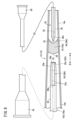
- FIG. 2 is an enlarged plan view of the distal end of the antegrade catheter of FIG.
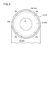
- FIG. 3 is a front view of the distal end of the antegrade catheter of FIG. 2 .
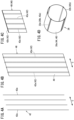
- 4A to 4D are explanatory diagrams showing the manufacturing process when manufacturing a marker.
- FIG. 5 is an explanatory diagram showing a state in which the tip of the antegrade catheter has been delivered to the upstream end of the lesion and the tip of the retrograde catheter has advanced into the lesion.
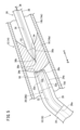
- FIG. 6 is an explanatory diagram showing a state in which a guidewire is inserted into the distal end of an antegrade catheter.
- FIG. 1 is a plan view showing the overall configuration of a catheter according to an embodiment of the present invention.
- FIG. 2 is an enlarged plan view of the distal end of the antegrade catheter of FIG.
- FIG. 3 is a front view of the distal
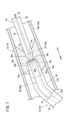
- FIG. 7 is an explanatory diagram showing the state in which the tip portion of a retrograde catheter is inserted into the tip portion of an antegrade catheter at a lesion site.
- FIG. 8 is a plan view showing the overall configuration of a catheter according to a modified example having no bent portion.
- the catheter 10 is used, for example, to treat a lesion 16 (such as a stenosis or occlusion) that has occurred in a blood vessel 14 of a living body 12.
- a lesion 16 such as a stenosis or occlusion
- the catheter 10 is used in lower limb vascular treatment to treat a CTO 16a (chronic total occlusion, lesion 16) that has occurred in a blood vessel 14 of the lower limb of the living body 12 using an antegrade approach.
- the catheter 10 may also be used to treat a lesion 16 in a lumen other than a blood vessel 14, for example, in a living organ such as a bile duct, trachea, esophagus, urethra, or other organ.
- the catheter 10 can be inserted into a blood vessel 14 of a living body 12 and advanced along the blood vessel 14.
- the catheter 10 is used, for example, as an antegrade catheter 18 used in an antegrade approach in lower limb vascular treatment.
- the catheter 10 is also referred to as an antegrade catheter 18.
- the tip 36a of a retrograde catheter 20 used in a retrograde approach can be inserted into the tip 24a of the antegrade catheter 18 (see Figure 7).
- Antegrade catheter 18 is a catheter that advances along blood vessels 14 of living body 12 toward the peripheral side of living body 12 (ankle side, in the direction of arrow A) in lower limb vascular treatment.
- the antegrade catheter 18 comprises a tubular first catheter body 24 having a first lumen 22 and a marker 26 disposed at the tip 24a of the first catheter body 24.
- the first catheter body 24 is formed from a resin material having flexibility.
- the first catheter body 24 is made of a resin material having a certain degree of flexibility, such as polyolefins such as polyethylene, polypropylene, and ethylene-propylene copolymers, polyesters such as polyethylene terephthalate and polybutylene terephthalate, polystyrene, polyvinyl chloride, polyurethane, polyamide, or various elastomers such as polyolefin elastomers, polyester elastomers, polyurethane elastomers, and polyamide elastomers, and may be blended, laminated, or arranged in multiple stages in the axial direction, or a reinforcing member may be arranged.
- polyolefins such as polyethylene, polypropylene, and ethylene-propylene copolymers
- polyesters such as polyethylene terephthalate and polybutylene terephthalate
- polystyrene polyvinyl
- the first lumen 22 is arranged inside the first catheter body 24.
- the first lumen 22 extends along the first catheter body 24. Since the antegrade catheter 18 is used to treat the CTO 16a, the tip 24a of the first catheter body 24 is not made of a soft material such as a rubber material (elastomer material), but has a hardness suitable for treating the CTO 16a.
- the outer peripheral surface of the tip 24a of the first catheter body 24 is tapered, decreasing in diameter toward the tip of the first catheter body 24 (in the direction of arrow A).
- the tip 24a of the first catheter body 24 has a bent portion 28.
- the bent portion 28 is positioned at a predetermined distance from the most distal end 24b of the first catheter body 24 in the proximal direction (in the direction of arrow B in FIG. 1).
- the bent portion 28 causes the tip 24a and the proximal end of the first catheter body 24 to be inclined relative to each other.
- the marker 26 comprises a cylindrical support 26a and an imaging portion 26b arranged on the support 26a.
- the marker 26 enables the tip position (leading end 24b) of the antegrade catheter 18 to be visualized under X-ray (radiation) imaging within the living body 12.
- the marker 26 is arranged on the tip portion 24a of the first catheter body 24.
- the support 26a is formed into a cylindrical shape from a transparent sheet-like film 44.
- the support 26a is formed from a resin material that is transmissible to radiation.
- the support 26a is embedded inside the tip 24a of the first catheter body 24.
- the support 26a has a predetermined length along the extension direction of the first catheter body 24.
- the imaging portion 26b includes a radiopaque material (e.g., gold, platinum, tungsten, or a mixture of these, etc.) and is disposed inside the support 26a.
- the imaging portion 26b is, for example, laminated to the sheet-like support 26a and covered by the support 26a.
- the contrast section 26b has a stripe section 32a extending in the axial direction of the support 26a and a ring section 32b located at the tip of the stripe section 32a.
- the stripe portion 32a is made of a wire that extends from the tip to the base of the support 26a.
- a plurality of stripe portions 32a are provided in the circumferential direction of the support 26a.
- the stripe portions 32a are equally spaced apart from each other in the circumferential direction of the support 26a. Below, a case where four stripe portions 32a are provided will be described.
- each of the multiple stripe portions 32a is parallel to the extension direction of the first lumen 22 (direction of arrows A and B).
- the thickness of the stripe portion 32a in the radial direction of the first catheter body 24 is constant along the stripe portion 32a.
- the tip of the stripe portion 32a extends to the ring portion 32b.
- the base end of the stripe portion 32a extends at least to the bent portion 28. In this embodiment, the stripe portion 32a extends to the base end side beyond the bent portion 28.
- the ring portion 32b is placed at the most distal end 26c of the marker 26.
- the ring portion 32b constitutes the tip of the marker 26.
- the ring portion 32b is formed in a ring shape from a wire.
- the ring portion 32b is placed along the circumferential direction of the support 26a.
- the ring portion 32b is connected to the tip of each stripe portion 32a.
- the multiple stripe portions 32a are connected together by the ring portion 32b.
- the tip of the marker 26 has a leading end 26c that is located in the most distal direction (arrow A direction).
- the leading end 26c of the marker 26 is the tip of the ring portion 32b.
- the leading end 26c of the marker 26 is located on the base end side (arrow B direction) of the leading end 24b of the first catheter body 24.
- the axial distance L between the leading end 26c of the marker 26 and the leading end 24b of the first catheter body 24 is 0.5 mm or less.
- the leading end 26c of the marker 26 is located within 0.5 mm on the base end side (arrow B direction) of the leading end 24b of the first catheter body 24.
- the leading end 26c of the marker 26 (ring portion 32b) is not exposed to the outside from the leading end 24b of the first catheter body 24.
- the base end of the first catheter body 24 includes a first hub 30.
- the first hub 30 is cylindrical.
- the base end of the first hub 30 is open.
- the retrograde catheter 20 used in lower limb vascular treatment.
- the retrograde catheter 20 advances along the blood vessels 14 of the living body 12 toward the central side of the living body 12 (toward the heart, in the direction of arrow B) during lower limb vascular treatment.
- the tip 36a of the retrograde catheter 20 can be inserted into the tip 24a of the antegrade catheter 18 (see Figure 7).
- the retrograde catheter 20 has a tubular second catheter body 36 with a second lumen 34.
- the second catheter body 36 is formed from a resin material having flexibility.
- the second catheter body 36 is made of a resin material having a certain degree of flexibility, such as polyolefins such as polyethylene, polypropylene, and ethylene-propylene copolymers, polyesters such as polyethylene terephthalate and polybutylene terephthalate, polystyrene, polyvinyl chloride, polyurethane, polyamide, or various elastomers such as polyolefin elastomers, polyester elastomers, polyurethane elastomers, and polyamide elastomers, and may be blended, laminated, or arranged in multiple stages in the axial direction, or a reinforcing body may be arranged.
- polyolefins such as polyethylene, polypropylene, and ethylene-propylene copolymers
- polyesters such as polyethylene terephthalate and polybutylene terephthalate
- polystyrene polyvinyl
- the diameter of the second catheter body 36 is smaller than the diameter of the first catheter body 24.
- the second lumen 34 is arranged inside the second catheter body 36.
- the second lumen 34 extends along the second catheter body 36.
- the second lumen 34 is a passage through which the guide wire 38 can be inserted. Because the retrograde catheter 20 is used to treat the CTO 16a, the tip 36a of the second catheter body 36 is not made of a soft material such as rubber (elastomer material) and has a hardness suitable for treating the CTO 16a.
- the tip 36a of the second catheter body 36 is tapered, the diameter of which decreases in the direction of the tip of the second catheter body 36 (in the direction of arrow B).
- the tip 36a of the second catheter body 36 is the end that is in the direction of advancement (in the direction of arrow B) when the retrograde catheter 20 is inserted into the blood vessel 14 and advanced.
- the tip 36a of the second catheter body 36 gradually tapers toward the most distal end 36b (in the direction of the tip, in the direction of arrow B).
- a contrast marker (not shown) is placed at the tip 36a of the second catheter body 36.
- the contrast marker contains a radiopaque material and allows the tip position of the retrograde catheter 20 to be visible under X-ray (radiation) imaging within the living body 12.
- the guidewire 38 is a wire made of a metallic material.
- the guidewire 38 is movably inserted into the second lumen 34 of the second catheter body 36.
- the tip 38a of the guidewire 38 can protrude from the most distal end 36b of the second catheter body 36 in the distal direction (central side, arrow B direction).
- the tip 38a of the guidewire 38 advances through the blood vessel 14 toward the central side (arrow B direction) ahead of the tip 36a of the second catheter body 36.
- the retrograde catheter 20 is guided through the blood vessel 14 by the guidewire 38.
- the base end of the second catheter body 36 is provided with a second hub 40.
- the second hub 40 is cylindrical.
- the base end of the second hub 40 is open.
- a guidewire 38 can be inserted into the second lumen 34 through the second hub 40.
- a plurality of wire materials 42 that constitute the stripe portion 32a and ring portion 32b of the contrast portion 26b are prepared.
- the wire material 42 is formed into a rod shape from a contrast wire material made of a metal material or a resin material containing a contrast agent.
- the plurality of wire materials 42 (hereinafter referred to as first wire materials 42a) that will become the stripe portion 32a are arranged at equal intervals in the width direction (direction of arrow C).
- a lamination process is performed in which all of the first wire materials 42a are sandwiched between a film 44 made of a resin material as shown in FIG. 4B.
- the film 44 forms the support body 26a in the marker 26.
- the marker manufacturing sheet 46 is cut to the desired length in the longitudinal direction of the first wire material 42a to form the marker manufacturing sheet 46 into small sheet pieces 48.
- the wire material 42 that will become the ring portion 32b (hereinafter, the second wire material 42b) is placed at the longitudinal end of the sheet piece 48.
- the second wire material 42b is placed so as to intersect with and straddle the multiple first wire materials 42a.
- the second wire material 42b is fixed to the end of the sheet piece 48 by, for example, heat welding.
- the sheet piece 48 is bent into a ring shape, and the widthwise ends of the sheet piece 48 are fused together by heat welding or the like.
- the multiple first wire materials 42a form the stripe portion 32a
- the second wire material 42b forms the ring portion 32b
- the sheet piece 48 forms the support body 26a.
- the blood vessel 14 in the lower limb in Figure 1 has a main tube 14a and first and second branch tubes 14b, 14c that are bifurcated downstream of the main tube 14a, and shows a case where a CTO 16a (lesion 16) has occurred in the first branch tube 14b.
- the first branch tube 14b and the second branch tube 14c are bent in directions that move away from each other downstream.
- the left side of the CTO 16a in the main tube section 14a and the first branch tube section 14b is the central side (heart side) and the upstream side of the blood flow.
- the right side of the CTO 16a in the first branch tube section 14b is the peripheral side (ankle side) and the downstream side of the blood flow.
- the blood vessel 14 (first branch tube section 14b) upstream (left) of the CTO 16a is referred to as the upstream blood vessel section 14d
- the blood vessel 14 (first branch tube section 14b) downstream (right) of the CTO 16a is referred to as the downstream blood vessel section 14e.
- the upstream blood vessel section 14d is an artery with a relatively large diameter of the blood vessel 14.
- the downstream blood vessel section 14e is a peripheral blood vessel with a smaller diameter of the blood vessel 14 than the upstream blood vessel section 14d.
- an antegrade approach is performed with an antegrade catheter 18 to a blood vessel 14 in the lower limb of a living body 12.
- a medical professional percutaneously inserts the tip 24a of the antegrade catheter 18 into the main tube 14a of the blood vessel 14.
- the tip 24a of the antegrade catheter 18 is advanced toward the peripheral side (in the direction of arrow A) toward the CTO 16a along a guide wire (not shown) within the blood vessel 14.
- the medical professional can visually recognize the marker 26 as a radiographic image via a display or the like under X-ray contrast, thereby performing the procedure while visually recognizing the tip position (leading edge 24b) of the antegrade catheter 18.
- the ring portion 32b of the marker 26 makes it possible to visually recognize the marker 26 from any circumferential position of the tip 24a of the antegrade catheter 18 (see FIG. 3).
- a medical professional (not shown) can rotate the antegrade catheter 18 and point the tip 24a toward the first branch pipe section 14b, allowing the tip 24a of the antegrade catheter 18 to be advanced appropriately along the first branch pipe section 14b.
- a medical professional can rotate the antegrade catheter 18 and point the tip 24a toward the first branch pipe section 14b, allowing the tip 24a of the antegrade catheter 18 to be advanced appropriately along the first branch pipe section 14b.
- the tip 24a of the antegrade catheter 18 is bent at the bend section 28, it is easy to advance the tip 24a toward the bent first branch pipe section 14b.
- the tip 24a (leading edge 24b) of the antegrade catheter 18 is delivered to the upstream end of the CTO 16a along the upstream blood vessel 14d.
- the upstream end of the CTO 16a has a protruding portion 50 that is convex toward the upstream blood vessel 14d (in the direction of arrow B).
- the leading edge 24b of the antegrade catheter 18 comes into contact with the protruding portion 50.
- a medical professional (not shown) can use the marker 26 to confirm the position of the tip 24a of the antegrade catheter 18 as a radiological image on a display or the like.
- a retrograde approach is performed to deliver the tip 36a of the retrograde catheter 20 along the downstream vascular portion 14e to the CTO 16a.
- the tip 36a of the retrograde catheter 20 is percutaneously inserted into the downstream vascular portion 14e of the blood vessel 14 (see FIG. 1).
- the guidewire 38 is inserted into the second lumen 34 of the retrograde catheter 20.
- the tip 36a of the retrograde catheter 20 is advanced toward the central side (arrow B direction) along the guidewire 38 toward the CTO 16a.
- the direction of advancement of the antegrade catheter 18 first direction, toward the peripheral side
- the direction of advancement of the retrograde catheter 20 second direction, toward the central side
- the tip 36a of the retrograde catheter 20 is delivered to the downstream end of the CTO 16a along the downstream blood vessel portion 14e.
- the downstream end of the CTO 16a has a recessed portion 52 that is recessed toward the upstream blood vessel portion 14d.
- the leading end 36b of the retrograde catheter 20 is inserted into the recessed portion 52.
- the tip 36a of the retrograde catheter 20 advances from the recess 52 into the interior of the CTO 16a.
- the tip 36a (leading edge 36b) of the retrograde catheter 20 excavates the CTO 16a, forming a perforation 54.
- the perforation 54 is formed from the bottom of the recess 52 toward the protrusion 50. As the retrograde catheter 20 advances, the perforation 54 penetrates all the way to the upstream end (protrusion 50) of the CTO 16a.
- the tip of the guidewire 38 penetrates the CTO 16a and protrudes from the protrusion 50 in the distal direction.
- a medical professional (not shown) checks the relative positions of the marker 26 of the antegrade catheter 18 and the tip 38a of the guidewire 38 under X-ray fluoroscopy, and adjusts the direction of the guidewire 38 so that the tip 38a of the guidewire 38 is parallel to the stripe portion 32a of the marker 26. After the guidewire 38 and the stripe portion 32a are made parallel, the tip of the guidewire 38 is advanced toward the center of the ring portion 32b of the marker 26. The tip 38a of the guidewire 38 is inserted into the first lumen 22 of the first catheter body 24.
- the guidewire 38 can be advanced toward the antegrade catheter 18 along the stripe portion 32a of the marker 26, allowing the guidewire 38 to be easily and reliably inserted into the first lumen 22.
- the tip 24a (leading edge 24b) of the antegrade catheter 18 advances along the perforation 54 into the interior of the CTO 16a.
- the tip 36a of the retrograde catheter 20 is inserted into the first lumen 22 of the tip 24a of the antegrade catheter 18.
- the tip 24a of the antegrade catheter 18 is smoothly inserted into the CTO 16a along the perforation 54.
- the tip 24a of the antegrade catheter 18 pushes the perforation 54 radially outward.
- the retrograde catheter 20 is removed.
- a balloon catheter (not shown) is inserted into the first lumen 22 of the antegrade catheter 18, and the balloon catheter is delivered to the CTO 16a.
- the CTO 16a is treated with the balloon catheter. Note that after a guidewire (not shown) is inserted into the first lumen 22 of the antegrade catheter 18, the antegrade catheter 18 may be removed to leave the guidewire in place, and the balloon catheter may be delivered to the CTO 16a along the guidewire (not shown).
- the insertion of the tip 36a of the retrograde catheter 20 into the tip 24a of the antegrade catheter 18 is not limited to being performed inside the CTO 16a.
- the tip 36a of the retrograde catheter 20 may be inserted into the tip 24a of the antegrade catheter 18 in the upstream vascular section 14d or downstream vascular section 14e near the CTO 16a.
- the catheter 10 used as the antegrade catheter 18 is not limited to a configuration having a bent portion 28. As shown in FIG. 8, the catheter 10a (antegrade catheter 18a) may have a first catheter body 25 that is linear along the axial direction. The catheter 10a is ideal for use in treating lower limb blood vessels, for example, in unbranched blood vessels 14.
- the stripe portion 32a of the marker 26 and the first lumen 22 are arranged in parallel, so that when a medical professional inserts the guidewire 38 from the tip portion 24a of the first catheter body 24 into the first lumen 22 under X-ray imaging, the medical professional can easily align the guidewire 38 and the first catheter body 24 coaxially while visually checking the stripe portion 32a, and insert the guidewire 38 into the first lumen 22 of the first catheter body 24.
- This makes it possible to easily align the guidewire 38 and the first catheter body 24, and reduces the amount of radiation exposure to the medical professional and the living body 12 when the medical professional works under X-ray imaging.
- the tip 24a of the first catheter body 24 has a bent portion 28 at a position a predetermined distance away from the most distal end 24b of the first catheter body 24 in the proximal direction, and the stripe portion 32a extends at least to the bent portion 28. Therefore, even if the tip 24a of the first catheter body 24 has a bent portion 28, the guidewire 38 can be easily aligned coaxially with the first lumen 22 by the stripe portion 32a arranged parallel to the first lumen 22.
- the distance between the most distal end 26c of the marker 26 and the most distal end 24b of the first catheter body 24 in the axial direction of the first catheter body 24 is 0.5 mm or less, so when the antegrade catheter 18 is advanced along the blood vessel 14 of the living body 12, the tip position of the antegrade catheter 18 can be confirmed with high accuracy under X-ray imaging.
- the marker 26 has a ring portion 32b that is formed in a ring shape along the circumferential direction of the first catheter body 24 and constitutes the leading end 26c of the marker 26. Therefore, by visually checking the ring portion 32b under X-ray contrast, medical personnel can more easily and accurately confirm the leading end 26c of the marker 26, and therefore the tip position of the antegrade catheter 18 can be accurately confirmed.
- the ease of inserting the tip of the retrograde catheter 20 can be improved by inserting the guidewire 38 along the stripe portion 32a of the marker 26 located on the tip portion 24a.
- the present invention is not limited to the above disclosure, and various configurations may be adopted without departing from the gist of the present invention.
- the lesion 16 does not have to be a typical CTO 16a, but may be a severely stenosed lesion where a certain degree of blood flow is observed, or may be a mildly stenosed lesion to reduce the burden on the patient.
Landscapes
- Health & Medical Sciences (AREA)
- Life Sciences & Earth Sciences (AREA)
- Biophysics (AREA)
- Pulmonology (AREA)
- Engineering & Computer Science (AREA)
- Anesthesiology (AREA)
- Biomedical Technology (AREA)
- Heart & Thoracic Surgery (AREA)
- Hematology (AREA)
- Animal Behavior & Ethology (AREA)
- General Health & Medical Sciences (AREA)
- Public Health (AREA)
- Veterinary Medicine (AREA)
- Media Introduction/Drainage Providing Device (AREA)
Abstract
カテーテル(10)(順行性カテーテル(18))は、生体(12)の血管(14)に沿って進行可能であり、第1ルーメン(22)を有した管状の第1カテーテル本体(24)と、放射線不透過性の材料を含み、第1カテーテル本体(24)の先端部(24a)に配置されたマーカ(26)とを備える。マーカ(26)は、第1ルーメン(22)の延在方向と平行なストライプ部(32a)を有する。
Description
本発明は、生体の管腔内に挿入するカテーテルに関する。
特開2004-229812号公報には、カテーテルを血管内に導入する際にガイドするシースイントロデューサが開示されている。シースイントロデューサは、管状のシースチューブを有し、シースチューブの先端に3本の造影部を有する。3本の造影部は、シースチューブの周方向に互いに離間し、シースチューブの長手方向にそれぞれ延在するストライプ状である。血管内にシースチューブが挿入されたとき、放射線透視下に造影部を画像で視認することで、シースチューブの先端位置を確認する。
特開2004-229812号公報のシースチューブの先端は、先端方向に向けて外周面がテーパ状に形成される。放射線透視下にシースチューブの先端を確認するとき、医療従事者はシースチューブの長手方向と直交する方向から視認することになる。このとき、3本の造影部は、先端の外周面に沿って斜め形状(テーパ状)に表示される。
そのため、放射線画像を見ながらシースチューブの先端開口に対してガイドワイヤを挿入する際、斜めに表示される3本の造影部を目安として、シースチューブの先端に対してガイドワイヤをまっすぐに位置合わせして挿入することが難しい。シースチューブの先端とガイドワイヤとの位置合わせのために、医療従事者が様々な角度から放射線画像を見ることで、作業時間の増加を招き、それに伴って、医療従事者及び患者に対する放射線の被曝量が増加する。
(1)本発明の第1の態様は、生体の管腔内に挿入され前記管腔に沿って進行可能なカテーテルであって、ルーメンを有した管状のカテーテル本体と、放射線不透過性の材料を含み、前記カテーテル本体の先端部に配置されたマーカと、を備え、前記マーカは、前記ルーメンの延在方向と平行なストライプ部を有する、カテーテルである。
このカテーテルによれば、マーカのストライプ部とルーメンとが平行に配置されるため、放射線透視下でルーメンに対してカテーテル本体の先端部からルーメンへとガイドワイヤを挿入するとき、ストライプ部を視認しながらガイドワイヤとカテーテル本体とを容易に同軸に位置合わせして、カテーテル本体のルーメンにガイドワイヤを挿入することができる。ガイドワイヤとカテーテル本体との位置合わせが容易であるため、放射線透視下で作業を行う際の医療従事者及び生体に対する放射線の被曝量を低減することができる。
(2)上記の(1)記載のカテーテルにおいて、前記カテーテル本体の前記先端部は、前記カテーテル本体の最先端から基端方向に所定距離だけ離れた位置に屈曲部を有し、前記ストライプ部は、少なくとも前記屈曲部まで延在してもよい。
この構成により、カテーテル本体の先端部に屈曲部を有していても、ルーメンと平行に設けられたストライプ部によってガイドワイヤを容易に同軸に位置合わせして挿入することができる。
(3)上記の(1)記載のカテーテルにおいて、前記カテーテル本体の軸方向における前記マーカの最先端と前記カテーテル本体の最先端との距離は、0.5mm以下であってもよい。
この構成により、カテーテルの先端部に配置されたマーカの最先端とカテーテル本体の最先端との軸方向距離が0.5mm以下であるため、生体の管腔に沿ってカテーテルを進行させる際、放射線透視下でカテーテルの先端位置を精度よく確認することができる。
(4)上記の(1)記載のカテーテルにおいて、前記マーカは、前記カテーテル本体の周方向に沿って環状に形成され前記マーカの最先端を構成するリング部を有してもよい。
この構成により、放射線透視下でリング部を視認することで、より容易且つ正確にマーカの最先端を確認し、カテーテルの先端位置を精度よく確認することができる。
(5)上記の(1)~(4)のいずれか1つに記載のカテーテルにおいて、前記カテーテルは、前記管腔に沿って前記生体の末梢側に進行する順行性カテーテルであってもよい。
この構成により、順行性カテーテルの先端に対して逆行性カテーテルの先端を挿入するとき、マーカのストライプ部に沿って逆行性カテーテルに挿通されたガイドワイヤを挿入することで、逆行性カテーテルの挿入性を高めることができる。
(6)本発明の第2の態様は、生体の管腔に沿って前記生体の末梢側に進行する順行性カテーテルと、前記管腔に沿って前記生体の中枢側に進行する逆行性カテーテルとを用いて、前記管腔内の病変部の治療を行う治療方法であって、前記順行性カテーテルは、第1ルーメンを有した管状の第1カテーテル本体と、放射線不透過性の材料を含み、前記第1カテーテル本体の先端部に配置されたマーカと、を備え、前記マーカは、前記第1ルーメンの延在方向と平行なストライプ部を有し、前記逆行性カテーテルは、第2ルーメンを有した管状の第2カテーテル本体を備え、前記治療方法は、前記生体の前記管腔内において、前記順行性カテーテルを末梢側に進行させる工程と、前記第2ルーメンにガイドワイヤが挿通された前記逆行性カテーテルを前記中枢側に進行させる工程と、放射線透視下で前記マーカの前記ストライプ部と前記ガイドワイヤの位置を確認しながら、前記第1ルーメンに前記ガイドワイヤの先端を挿入し、前記逆行性カテーテルの先端を前記順行性カテーテルの先端に挿入する工程と、を有する、治療方法である。
本発明によれば、カテーテルにおいて、マーカのストライプ部とルーメンとが平行に配置されているため、放射線透視下でルーメンに対してカテーテル本体の先端部からルーメンへとガイドワイヤを挿入するとき、ストライプ部を視認しながらガイドワイヤとカテーテル本体とを容易に同軸に位置合わせして、カテーテル本体のルーメンにガイドワイヤを挿入することができる。ガイドワイヤとカテーテル本体との位置合わせが容易であるため、放射線透視下で作業を行う際の生体に対する被曝量を低減することが可能である。
図1に示されるように、本実施形態に係るカテーテル10は、例えば、生体12の血管14内に生じた病変部16(狭窄部又は閉塞部等)の治療に用いられる。具体的には、カテーテル10は、生体12の下肢の血管14内に生じたCTO16a(慢性完全閉塞病変:Chronic Total Occlusion、病変部16)を順行性アプローチによって治療する下肢血管治療に用いられる。なお、カテーテル10は、血管14以外の管腔、例えば、胆管、気管、食道、尿道、その他の臓器等の生体器官内の病変部16を治療するためのものであってもよい。
カテーテル10は、生体12の血管14内に挿入され血管14に沿って進行可能である。カテーテル10は、例えば、下肢血管治療において順行性アプローチに用いられる順行性カテーテル18として用いられる。以下、カテーテル10を、順行性カテーテル18ともいう。下肢血管治療において、順行性カテーテル18の先端部24aには、逆行性アプローチで用いられる逆行性カテーテル20の先端部36aが挿入可能である(図7参照)。
順行性カテーテル18は、下肢血管治療において生体12の血管14に沿って生体12の末梢側(足首側、矢印A方向)に進行するカテーテルである。
図2に示すように、順行性カテーテル18は、第1ルーメン22を有した管状の第1カテーテル本体24と、第1カテーテル本体24の先端部24aに配置されたマーカ26とを備える。
第1カテーテル本体24は、可撓性を有する樹脂材料から形成される。具体的には、第1カテーテル本体24の構成材料としては、ポリエチレン、ポリプロピレン、エチレン-プロピレン共重合体等のポリオレフィン、ポリエチレンテレフタレート、ポリブチレンテレフタレート等のポリエステル、ポリスチレン、ポリ塩化ビニル、ポリウレタン、ポリアミドあるいはポリオレフィンエラストマー、ポリエステルエラストマー、ポリウレタンエラストマー、ポリアミドエラストマー等各種エラストマー等のある程度の可撓性を備える樹脂材料が使用され、ブレンド、積層あるいは軸方向に多段的に配置してもよく、補強体を配置してもよい。第1ルーメン22は、第1カテーテル本体24の内部に配置される。第1ルーメン22は、第1カテーテル本体24に沿って延在する。順行性カテーテル18はCTO16aの治療に用いられるため、第1カテーテル本体24の先端部24aは、ゴム材(エラストマー材)のような軟質材からなるものではなく、CTO16aの治療に適した硬さを有する。
図1に示すように、第1カテーテル本体24の先端部24aの外周面は、第1カテーテル本体24の先端方向(矢印A方向)に向かって縮径するテーパ状である。第1カテーテル本体24の先端部24aは、屈曲部28を有する。屈曲部28は、第1カテーテル本体24の最先端24bから基端方向(図1中、矢印B方向)に所定距離だけ離れた位置に配置される。屈曲部28によって、第1カテーテル本体24の先端部24aと基端とが相対的に傾斜している。
図2に示すように、マーカ26は、筒状の支持体26aと、支持体26aに配置される造影部26bとを備える。マーカ26は、生体12内で順行性カテーテル18の先端位置(最先端24b)をX線(放射線)造影下で視認可能とするものである。マーカ26は、第1カテーテル本体24の先端部24aに配置される。
支持体26aは、透明なシート状のフィルム44から筒状に形成される。支持体26aは、放射線が透過可能な樹脂材料で形成される。支持体26aは、第1カテーテル本体24の先端部24aの内部に埋設される。支持体26aは、第1カテーテル本体24の延在方向に沿って所定長さを有する。
造影部26bは、放射線不透過性の材料(例えば、金、白金、タングステンあるいはこれらの混合物等)を含み、支持体26aの内部に配置される。造影部26bは、例えば、シート状の支持体26aにラミネートされ支持体26aによって覆われる。
造影部26bは、支持体26aの軸方向に延在するストライプ部32aと、ストライプ部32aの先端に配置されるリング部32bとを有する。
ストライプ部32aは、支持体26aの先端から基端まで延在するワイヤからなる。ストライプ部32aは、支持体26aの周方向に複数設けられる。各ストライプ部32aは、支持体26aの周方向において互いに等間隔離間する。以下、4本のストライプ部32aを備える場合について説明する。
第1カテーテル本体24の先端部24aにマーカ26が配置されたとき、複数のストライプ部32aの各々と第1ルーメン22の延在方向(矢印A、B方向)とが平行である。第1カテーテル本体24の径方向におけるストライプ部32aの厚みは、ストライプ部32aに沿って一定である。ストライプ部32aの先端は、リング部32bまで延在する。ストライプ部32aの基端は、少なくとも屈曲部28まで延在する。本実施形態では、ストライプ部32aは、屈曲部28よりも基端側まで延在する。
リング部32bは、マーカ26の最先端26cに配置される。リング部32bは、マーカ26の先端部を構成する。リング部32bは、ワイヤから環状に形成される。リング部32bは、支持体26aの周方向に沿って配置される。各ストライプ部32aの先端にリング部32bが接続される。リング部32bによって複数のストライプ部32aが一体に繋がる。第1カテーテル本体24の先端部24aにマーカ26が配置されたとき、第1カテーテル本体24の周方向に沿ってリング部32bが配置される。
マーカ26の先端部は、最も先端方向(矢印A方向)に配置される最先端26cを有する。マーカ26の最先端26cは、リング部32bの先端である。マーカ26の最先端26cは、第1カテーテル本体24の最先端24bより基端側(矢印B方向)に配置される。第1カテーテル本体24の軸方向(矢印A、B方向)において、マーカ26の最先端26cと第1カテーテル本体24の最先端24bとの軸方向距離Lは、0.5mm以下である。すなわち、マーカ26の最先端26cは、第1カテーテル本体24の最先端24bから基端側(矢印B方向)に0.5mm以内に配置される。マーカ26の最先端26c(リング部32b)は、第1カテーテル本体24の最先端24bから外部に露出しない。
図1に示すように、第1カテーテル本体24の基端は、第1ハブ30を備える。第1ハブ30は筒状である。第1ハブ30の基端は開口する。
次に、下肢血管治療に用いられる逆行性カテーテル20について説明する。図1に示すように、逆行性カテーテル20は、下肢血管治療において生体12の血管14に沿って生体12の中枢側(心臓側、矢印B方向)に進行する。逆行性カテーテル20が中枢側に向けて進行したとき、逆行性カテーテル20の先端部36aが順行性カテーテル18の先端部24aに挿入可能である(図7参照)。
逆行性カテーテル20は、第2ルーメン34を有した管状の第2カテーテル本体36を有する。
第2カテーテル本体36は、可撓性を有する樹脂材料から形成される。具体的には、第2カテーテル本体36の構成材料としては、ポリエチレン、ポリプロピレン、エチレン-プロピレン共重合体等のポリオレフィン、ポリエチレンテレフタレート、ポリブチレンテレフタレート等のポリエステル、ポリスチレン、ポリ塩化ビニル、ポリウレタン、ポリアミドあるいはポリオレフィンエラストマー、ポリエステルエラストマー、ポリウレタンエラストマー、ポリアミドエラストマー等各種エラストマー等のある程度の可撓性を備える樹脂材料が使用され、ブレンド、積層あるいは軸方向に多段的に配置してもよく、補強体を配置してもよい。第2カテーテル本体36の直径は、第1カテーテル本体24の直径より小さい。第2ルーメン34は、第2カテーテル本体36の内部に配置される。第2ルーメン34は、第2カテーテル本体36に沿って延在する。第2ルーメン34は、ガイドワイヤ38が挿通可能な通路である。逆行性カテーテル20はCTO16aの治療に用いられるため、第2カテーテル本体36の先端部36aは、ゴム材(エラストマー材)のような軟質材からなるものではなく、CTO16aの治療に適した硬さを有する。
第2カテーテル本体36の先端部36aは、第2カテーテル本体36の先端方向(矢印B方向)に向かって縮径するテーパ状である。第2カテーテル本体36の先端部36aは、逆行性カテーテル20を血管14内に挿入して進行させるとき、進行方向(矢印B方向)となる端部である。すなわち、第2カテーテル本体36の先端部36aは、最先端36b(先端方向、矢印B方向)に向けて徐々に先細状となる。
第2カテーテル本体36の先端部36aには、図示しない造影マーカが配置される。造影マーカは、放射線不透過性の材料を含み、生体12内で逆行性カテーテル20の先端位置をX線(放射線)造影下で視認可能とするものである。
ガイドワイヤ38は、金属材料からなるワイヤである。ガイドワイヤ38は、第2カテーテル本体36の第2ルーメン34に移動可能に挿通される。ガイドワイヤ38の先端部38aは、第2カテーテル本体36の最先端36bから先端方向(中枢側、矢印B方向)に突出可能である。第2カテーテル本体36の先端部36aに先行して、ガイドワイヤ38の先端部38aが、血管14を中枢側(矢印B方向)に向かって進行する。ガイドワイヤ38によって逆行性カテーテル20が血管14内をガイドされる。
第2カテーテル本体36の基端は、第2ハブ40を備える。第2ハブ40は筒状である。第2ハブ40の基端は開口する。第2ハブ40を通じて第2ルーメン34にガイドワイヤ38を挿入可能である。
次に、マーカ26の製造方法について図4A~図4Dを参照しながら説明する。
先ず、図4Aに示すように、造影部26bのストライプ部32a及びリング部32bを構成する複数のワイヤ材42を準備する。ワイヤ材42は、金属材料からなる造影性線材、又は、造影剤の含有された樹脂材料から棒状に形成される。ストライプ部32aとなる複数のワイヤ材42(以下、第1ワイヤ材42aという)を幅方向(矢印C方向)に等間隔離間させて配置する。
図4Aのように複数の第1ワイヤ材42aが配置された後、図4Bに示すように、第1ワイヤ材42aの全てを樹脂材料からなるフィルム44によって挟み込むラミネート加工を行う。これにより、フィルム44によって複数の第1ワイヤ材42aが所定位置で固定されたマーカ製造用シート46が形成される。フィルム44は、マーカ26において支持体26aを構成する。
図4Cに示すように、第1ワイヤ材42aの長手方向において、マーカ製造用シート46を所望の長さに切断してマーカ製造用シート46を小片のシート片48とする。シート片48の長手方向端部に、リング部32bとなるワイヤ材42(以下、第2ワイヤ材42b)を配置する。第2ワイヤ材42bは、複数の第1ワイヤ材42aと交差し、且つ、複数の第1ワイヤ材42aを跨ぐように配置する。第2ワイヤ材42bは、例えば、熱溶着等によってシート片48の端部に固定される。
図4Dに示すように、シート片48を環状に湾曲させ、シート片48の幅方向端部を互いに熱溶着等によって融着する。これにより、第1及び第2ワイヤ材42a、42bが覆われた筒状のマーカ26が形成される。複数の第1ワイヤ材42aがストライプ部32aであり、第2ワイヤ材42bが環状のリング部32bであり、シート片48が支持体26aである。
次に、カテーテル10を順行性カテーテル18として用いて下肢血管治療を行う場合について説明する。図1の下肢の血管14は、本管部14aと、本管部14aの下流側で二股状に分岐した第1及び第2分岐管部14b、14cとを有し、第1分岐管部14b内にCTO16a(病変部16)が生じた場合を示す。第1分岐管部14bと第2分岐管部14cとが、下流に向けて互いに離間する方向へ屈曲している。
図1に示す血管14において、本管部14a及び第1分岐管部14bにおけるCTO16aの左方は、中枢側(心臓側)であり血液の流れの上流側である。第1分岐管部14bにおけるCTO16aの右方が、末梢側(足首側)であり血液の流れの下流側である。以下、CTO16aに対して上流側(左方)の血管14(第1分岐管部14b)を上流側血管部14dといい、CTO16aに対して下流側(右方)の血管14(第1分岐管部14b)を下流側血管部14eという。上流側血管部14dは、血管14の管径が比較的太い動脈である。下流側血管部14eは、上流側血管部14dに比べて血管14の管径が細い末梢血管である。
先ず、図1に示すように、生体12の下肢の血管14に対する順行性カテーテル18の順行性アプローチを行う。図示しない医療従事者が順行性カテーテル18の先端部24aを経皮的に血管14の本管部14aに挿入する。順行性カテーテル18の先端部24aを血管14内で図示しないガイドワイヤに沿ってCTO16aに向けて末梢側(矢印A方向)へと進行させる。このとき、図示しない医療従事者は、X線造影下でマーカ26をディスプレイ等を介して放射線画像として視認することで、順行性カテーテル18の先端位置(最先端24b)を視認しながら手技を行うことが可能である。マーカ26のリング部32bによって、順行性カテーテル18の先端部24aを周方向のいずれの位置から見てもマーカ26を視認することが可能である(図3参照)。
第1分岐管部14bと第2分岐管部14cとの分岐部において、図示しない医療従事者が順行性カテーテル18を回転させ、先端部24aを第1分岐管部14bに向けることで、順行性カテーテル18の先端部24aを第1分岐管部14bに沿って好適に進行させることができる。このとき、順行性カテーテル18の先端部24aが屈曲部28を有して屈曲しているため、屈曲した第1分岐管部14bへの先端部24aの進行が容易である。
図5に示すように、上流側血管部14dに沿って順行性カテーテル18の先端部24a(最先端24b)がCTO16aの上流側端部に送達される。CTO16aの上流側端部は、上流側血管部14d側(矢印B方向)に向けて凸状となった突状部50を有する。順行性カテーテル18の最先端24bが突状部50に接触する。図示しない医療従事者は、マーカ26によって順行性カテーテル18の先端部24aの位置をディスプレイ等で放射線画像として確認することができる。
順行性カテーテル18の先端部24aがCTO16aの上流側端部に送達された後、下流側血管部14eに沿って逆行性カテーテル20の先端部36aをCTO16aに送達する逆行性アプローチを行う。
逆行性カテーテル20の先端部36aを、経皮的に血管14の下流側血管部14eに挿入する(図1参照)。このとき、逆行性カテーテル20の第2ルーメン34には、ガイドワイヤ38が挿通されている。ガイドワイヤ38の先端部38aを逆行性カテーテル20の最先端36bから先端方向(矢印B方向)に突出させた状態で、逆行性カテーテル20の先端部36aをガイドワイヤ38に沿ってCTO16aに向けて中枢側(矢印B方向)へ進行させる。順行性カテーテル18の進行方向(第1方向、末梢側へ向かう)と逆行性カテーテル20の進行方向(第2方向、中枢側へ向かう)とが反対方向である。換言すれば、逆行性カテーテル20の先端部36aは、順行性カテーテル18の先端部24aに向けて進行する。
下流側血管部14eに沿って逆行性カテーテル20の先端部36aがCTO16aの下流側端部に送達される。CTO16aの下流側端部は、上流側血管部14d側に向けて窪んだ窪み部52を有する。逆行性カテーテル20の最先端36bが窪み部52に挿入される。
逆行性カテーテル20の先端部36aをさらに進行させることで、窪み部52からCTO16aの内部に先端部36aが進行していく。逆行性カテーテル20の先端部36a(最先端36b)によって、CTO16aが掘られて穿孔54が形成される。穿孔54は、窪み部52の底部から突状部50に向けて形成される。逆行性カテーテル20の進行に伴って、CTO16aの上流側端部(突状部50)まで穿孔54が貫通する。
図6に示すように、ガイドワイヤ38の先端がCTO16aを貫通し、突状部50から先端方向へ突出する。図示しない医療従事者は、X線透視下で順行性カテーテル18のマーカ26とガイドワイヤ38の先端部38aとの相対位置を確認し、ガイドワイヤ38の先端部38aが、マーカ26のストライプ部32aと平行となるようにガイドワイヤ38の方向を調整する。ガイドワイヤ38とストライプ部32aとを平行とした後、ガイドワイヤ38の先端をマーカ26のリング部32bの中心に向けて進行させる。ガイドワイヤ38の先端部38aが、第1カテーテル本体24の第1ルーメン22に挿入される。
このとき、順行性カテーテル18の先端部24aが屈曲部28を有し、先端部24aが基端に対して傾斜していた場合でも、マーカ26のストライプ部32aに沿ってガイドワイヤ38を順行性カテーテル18側に向けて進行させることで、ガイドワイヤ38を第1ルーメン22に容易且つ確実に挿入することができる。
図7に示すように、ガイドワイヤ38に沿って、順行性カテーテル18の先端部24aと逆行性カテーテル20の先端部36aとを互いに接近させることで、順行性カテーテル18の先端部24a(最先端24b)が穿孔54に沿ってCTO16aの内部に進行する。CTO16aの内部において、逆行性カテーテル20の先端部36aが、順行性カテーテル18の先端部24aの第1ルーメン22に挿入される。このとき、CTO16aに穿孔54が形成されているため、順行性カテーテル18の先端部24aは穿孔54に沿って円滑にCTO16a内に挿入される。順行性カテーテル18の先端部24aによって、穿孔54が径方向外方に押し広げられる。
順行性カテーテル18の先端部24aがCTO16aの内部の所定位置に留置された後、逆行性カテーテル20が抜去される。図示しないバルーンカテーテルが順行性カテーテル18の第1ルーメン22に挿通され、バルーンカテーテルがCTO16aまで送達される。バルーンカテーテルによってCTO16aの治療が行われる。なお、順行性カテーテル18の第1ルーメン22に図示しないガイドワイヤを挿通させた後、順行性カテーテル18を抜去してガイドワイヤを留置し、図示しないガイドワイヤに沿ってバルーンカテーテルをCTO16aまで送達してもよい。
順行性カテーテル18の先端部24aに対する逆行性カテーテル20の先端部36aの挿入は、CTO16aの内部で行われる場合に限定されない。CTO16a近傍となる上流側血管部14d又は下流側血管部14eにおいて、逆行性カテーテル20の先端部36aを順行性カテーテル18の先端部24aに挿入してもよい。
なお、順行性カテーテル18として用いられるカテーテル10は、屈曲部28を備える構成に限定されない。図8に示すように、軸方向に沿って直線状の第1カテーテル本体25を備えるカテーテル10a(順行性カテーテル18a)であってもよい。カテーテル10aは、例えば、分岐していない血管14の下肢血管治療に用いると最適である。
以上のように、本発明の実施形態では、カテーテル10(順行性カテーテル18)において、マーカ26のストライプ部32aと第1ルーメン22とが平行に配置されるため、医療従事者がX線造影下で第1ルーメン22に対して第1カテーテル本体24の先端部24aからガイドワイヤ38を第1ルーメン22へと挿入するとき、ストライプ部32aを視認しながらガイドワイヤ38と第1カテーテル本体24とを容易に同軸に位置合わせして、第1カテーテル本体24の第1ルーメン22にガイドワイヤ38を挿入することができる。これにより、ガイドワイヤ38と第1カテーテル本体24との位置合わせを容易に行うことが可能となり、医療従事者がX線造影下で作業を行う際の医療従事者及び生体12に対する被曝量を低減することができる。
第1カテーテル本体24の先端部24aは、第1カテーテル本体24の最先端24bから基端方向に所定距離だけ離れた位置に屈曲部28を有し、ストライプ部32aが、少なくとも屈曲部28まで延在しているため、第1カテーテル本体24の先端部24aに屈曲部28を有していても、第1ルーメン22と平行に設けられたストライプ部32aによってガイドワイヤ38を容易に同軸に位置合わせできる。
第1カテーテル本体24の軸方向におけるマーカ26の最先端26cと第1カテーテル本体24の最先端24bとの距離は、0.5mm以下であるため、生体12の血管14に沿って順行性カテーテル18を進行させるとき、X線造影下で順行性カテーテル18の先端位置を精度よく確認することができる。
マーカ26は、第1カテーテル本体24の周方向に沿って環状に形成されマーカ26の最先端26cを構成するリング部32bを有するため、医療従事者がX線造影下でリング部32bを視認することで、より容易且つ正確にマーカ26の最先端26cを確認し、それに伴って、順行性カテーテル18の先端位置を精度よく確認することができる。
順行性カテーテル18の先端に対して逆行性カテーテル20の先端を挿入するとき、先端部24aに配置されたマーカ26のストライプ部32aに沿ってガイドワイヤ38を挿入することで、逆行性カテーテル20の先端の挿入性を高めることができる。
なお、本発明は、上述した開示に限らず、本発明の要旨を逸脱することなく、種々の構成を採り得る。例えば、病変部16は、代表的なCTO16aでなくても血流がある程度認められる強度の狭窄病変部でもよく、患者の負担を減らすために軽度の狭窄病変部であってもよい。
Claims (6)
- 生体の管腔内に挿入され前記管腔に沿って進行可能なカテーテルであって、
ルーメンを有した管状のカテーテル本体と、
放射線不透過性の材料を含み、前記カテーテル本体の先端部に配置されたマーカと、
を備え、
前記マーカは、前記ルーメンの延在方向と平行なストライプ部を有する、カテーテル。 - 請求項1記載のカテーテルにおいて、
前記カテーテル本体の前記先端部は、前記カテーテル本体の最先端から基端方向に所定距離だけ離れた位置に屈曲部を有し、
前記ストライプ部は、少なくとも前記屈曲部まで延在する、カテーテル。 - 請求項1記載のカテーテルにおいて、
前記カテーテル本体の軸方向における前記マーカの最先端と前記カテーテル本体の最先端との距離は、0.5mm以下である、カテーテル。 - 請求項1記載のカテーテルにおいて、
前記マーカは、前記カテーテル本体の周方向に沿って環状に形成され前記マーカの最先端を構成するリング部を有する、カテーテル。 - 請求項1~4のいずれか1項に記載のカテーテルにおいて、
前記カテーテルは、前記管腔に沿って前記生体の末梢側に進行する順行性カテーテルである、カテーテル。 - 生体の管腔に沿って前記生体の末梢側に進行する順行性カテーテルと、前記管腔に沿って前記生体の中枢側に進行する逆行性カテーテルとを用いて、前記管腔内の病変部の治療を行う治療方法であって、
前記順行性カテーテルは、
第1ルーメンを有した管状の第1カテーテル本体と、
放射線不透過性の材料を含み、前記第1カテーテル本体の先端部に配置されたマーカと、
を備え、
前記マーカは、前記第1ルーメンの延在方向と平行なストライプ部を有し、
前記逆行性カテーテルは、第2ルーメンを有した管状の第2カテーテル本体を備え、
前記治療方法は、
前記生体の前記管腔内において、前記順行性カテーテルを末梢側に進行させる工程と、
前記第2ルーメンにガイドワイヤが挿通された前記逆行性カテーテルを前記中枢側に進行させる工程と、
放射線透視下で前記マーカの前記ストライプ部と前記ガイドワイヤの位置を確認しながら、前記第1ルーメンに前記ガイドワイヤの先端を挿入し、前記逆行性カテーテルの先端を前記順行性カテーテルの先端に挿入する工程と、を有する治療方法。
Applications Claiming Priority (2)
| Application Number | Priority Date | Filing Date | Title |
|---|---|---|---|
| JP2022163449A JP2025176721A (ja) | 2022-10-11 | 2022-10-11 | カテーテル |
| JP2022-163449 | 2022-10-11 |
Publications (1)
| Publication Number | Publication Date |
|---|---|
| WO2024080004A1 true WO2024080004A1 (ja) | 2024-04-18 |
Family
ID=90669370
Family Applications (1)
| Application Number | Title | Priority Date | Filing Date |
|---|---|---|---|
| PCT/JP2023/030568 Ceased WO2024080004A1 (ja) | 2022-10-11 | 2023-08-24 | カテーテル |
Country Status (2)
| Country | Link |
|---|---|
| JP (1) | JP2025176721A (ja) |
| WO (1) | WO2024080004A1 (ja) |
Citations (7)
| Publication number | Priority date | Publication date | Assignee | Title |
|---|---|---|---|---|
| JPS57501165A (ja) * | 1980-07-28 | 1982-07-08 | ||
| US5921978A (en) * | 1997-06-20 | 1999-07-13 | Ep Technologies, Inc. | Catheter tip steering plane marker |
| JP2001104487A (ja) * | 1999-10-06 | 2001-04-17 | Kanegafuchi Chem Ind Co Ltd | 薬剤注入カテーテル |
| JP2009268648A (ja) * | 2008-05-02 | 2009-11-19 | Nipro Corp | 医療用カテーテル |
| JP2011518615A (ja) * | 2008-04-23 | 2011-06-30 | レトロ・ヴァスキュラー・インコーポレーテッド | コントロールされた順行性および逆行性トラッキングを使用する閉塞した血管の再疎通 |
| US20160256120A1 (en) * | 2015-03-06 | 2016-09-08 | University Of Rochester | Catheter Detection, Tracking And Virtual Image Reconstruction |
| JP2021510106A (ja) * | 2018-01-05 | 2021-04-15 | ベクトン・ディキンソン・アンド・カンパニーBecton, Dickinson And Company | エコー源性のカテーテルおよびカテーテルシステム |
-
2022
- 2022-10-11 JP JP2022163449A patent/JP2025176721A/ja active Pending
-
2023
- 2023-08-24 WO PCT/JP2023/030568 patent/WO2024080004A1/ja not_active Ceased
Patent Citations (7)
| Publication number | Priority date | Publication date | Assignee | Title |
|---|---|---|---|---|
| JPS57501165A (ja) * | 1980-07-28 | 1982-07-08 | ||
| US5921978A (en) * | 1997-06-20 | 1999-07-13 | Ep Technologies, Inc. | Catheter tip steering plane marker |
| JP2001104487A (ja) * | 1999-10-06 | 2001-04-17 | Kanegafuchi Chem Ind Co Ltd | 薬剤注入カテーテル |
| JP2011518615A (ja) * | 2008-04-23 | 2011-06-30 | レトロ・ヴァスキュラー・インコーポレーテッド | コントロールされた順行性および逆行性トラッキングを使用する閉塞した血管の再疎通 |
| JP2009268648A (ja) * | 2008-05-02 | 2009-11-19 | Nipro Corp | 医療用カテーテル |
| US20160256120A1 (en) * | 2015-03-06 | 2016-09-08 | University Of Rochester | Catheter Detection, Tracking And Virtual Image Reconstruction |
| JP2021510106A (ja) * | 2018-01-05 | 2021-04-15 | ベクトン・ディキンソン・アンド・カンパニーBecton, Dickinson And Company | エコー源性のカテーテルおよびカテーテルシステム |
Also Published As
| Publication number | Publication date |
|---|---|
| JP2025176721A (ja) | 2025-12-05 |
Similar Documents
| Publication | Publication Date | Title |
|---|---|---|
| JP7757366B2 (ja) | 脈管再入カテーテル | |
| US11213657B2 (en) | Guide wire for medical devices, method of using the guidewire, and method for forming a covering on the guidewire | |
| US8197442B2 (en) | Interventional medical device system having a slotted section and radiopaque marker and method of making the same | |
| US20200147347A1 (en) | Vascular re-entry catheter | |
| US8864789B2 (en) | Interventional medical device system having a spiral section and radiopaque marker and method of making the same | |
| EP0610347B1 (en) | Fluoroscopically viewable guidewire for catheters | |
| US6491662B1 (en) | Catheter with stand-off structure | |
| US11547835B2 (en) | Systems, methods and apparatus for guiding and supporting catheters and methods of manufacture | |
| WO2013095986A1 (en) | Biliary system catheter | |
| JP2009273640A (ja) | ガイディングカテーテル | |
| US20220387758A1 (en) | Vascular re-entry catheter | |
| WO2012141747A2 (en) | Hypotube based support catheter | |
| US8585680B2 (en) | Endovascular device tip assembly incorporating a marker device and method for making the same | |
| JP2009539552A (ja) | ワイヤガイド括約筋切開刀 | |
| JP2011156115A (ja) | 医療用器具 | |
| JP2025183963A (ja) | カテーテル | |
| WO2012014860A1 (ja) | 医療用カテーテル | |
| JP2025176721A (ja) | カテーテル | |
| WO2024080003A1 (ja) | カテーテル及びカテーテルシステム | |
| JP2023018560A (ja) | カテーテル、カテーテルの製造方法、及び造影マーカのかしめ方法 | |
| US20250332381A1 (en) | Catheter and catheter system | |
| JP7555506B1 (ja) | 医療機器用補助具、ガイドワイヤアッセンブリ及び医療機器アッセンブリ | |
| US20250082898A1 (en) | Systems and methods of forming a continuous reinforced catheter shaft | |
| WO2024127750A1 (ja) | カテーテル | |
| JP2024100601A (ja) | カテーテル |
Legal Events
| Date | Code | Title | Description |
|---|---|---|---|
| 121 | Ep: the epo has been informed by wipo that ep was designated in this application |
Ref document number: 23877012 Country of ref document: EP Kind code of ref document: A1 |
|
| NENP | Non-entry into the national phase |
Ref country code: DE |
|
| 122 | Ep: pct application non-entry in european phase |
Ref document number: 23877012 Country of ref document: EP Kind code of ref document: A1 |
|
| NENP | Non-entry into the national phase |
Ref country code: JP |