WO2024079874A1 - 空気調和装置 - Google Patents
空気調和装置 Download PDFInfo
- Publication number
- WO2024079874A1 WO2024079874A1 PCT/JP2022/038341 JP2022038341W WO2024079874A1 WO 2024079874 A1 WO2024079874 A1 WO 2024079874A1 JP 2022038341 W JP2022038341 W JP 2022038341W WO 2024079874 A1 WO2024079874 A1 WO 2024079874A1
- Authority
- WO
- WIPO (PCT)
- Prior art keywords
- pressure
- refrigerant
- relay
- pipe
- outdoor
- Prior art date
- Legal status (The legal status is an assumption and is not a legal conclusion. Google has not performed a legal analysis and makes no representation as to the accuracy of the status listed.)
- Ceased
Links
Images









Classifications
-
- F—MECHANICAL ENGINEERING; LIGHTING; HEATING; WEAPONS; BLASTING
- F25—REFRIGERATION OR COOLING; COMBINED HEATING AND REFRIGERATION SYSTEMS; HEAT PUMP SYSTEMS; MANUFACTURE OR STORAGE OF ICE; LIQUEFACTION SOLIDIFICATION OF GASES
- F25B—REFRIGERATION MACHINES, PLANTS OR SYSTEMS; COMBINED HEATING AND REFRIGERATION SYSTEMS; HEAT PUMP SYSTEMS
- F25B47/00—Arrangements for preventing or removing deposits or corrosion, not provided for in another subclass
- F25B47/02—Defrosting cycles
Definitions
- This disclosure relates to an air conditioning device having a repeater.
- Patent Document 1 discloses an air conditioner constituting a two-pipe simultaneous heating and cooling operation system in which the refrigerant that has lost heat in the outdoor heat exchanger and become cold during defrosting operation is circulated only through the outdoor unit, main pipe, and relay unit, and the opening/closing state and direction of the valve are controlled so that the refrigerant that has lost heat in the outdoor heat exchanger and become cold is not allowed to flow into the branch pipes and indoor unit.
- the opening/closing state and direction of the valve are controlled so that the refrigerant that has lost heat in the outdoor heat exchanger and become cold is circulated only through the outdoor unit, main pipe, and relay unit, and is not allowed to flow into the extension branch pipe connecting the relay unit and the indoor unit, and into the indoor unit.
- the air conditioner of Patent Document 1 suppresses the temperature drop in the extension branch pipe, eliminating the need to reheat the extension branch pipe when heating is resumed, thereby shortening the time it takes to resume heating.
- Patent Document 1 the extension main pipe connecting the outdoor unit and the relay unit loses temperature as heat is absorbed by the low-temperature refrigerant, and so it is necessary to reheat these pipes when heating is resumed. Therefore, even in the air conditioning device of Patent Document 1, there is still room to further shorten the heating resume time.
- This disclosure has been made to solve the problems described above, and aims to provide an air conditioner that shortens the time it takes to return to heating mode from defrosting operation.
- the air conditioner according to the present disclosure includes an outdoor unit having a compressor that compresses a refrigerant, an outdoor flow path switching device that switches the connection direction of the piping through which the refrigerant discharged from the compressor flows, an outdoor heat exchanger that performs heat exchange between the air and the refrigerant, and an outdoor expansion valve that expands the refrigerant, an indoor unit having an indoor refrigerant heat exchanger that performs heat exchange between the refrigerant or heat medium and the air, a relay unit that relays the heat supplied from the outdoor unit via the refrigerant to the indoor unit via the refrigerant or heat medium, and a control device, and the control device performs a heating operation and a defrosting operation that removes frost that has formed on the outdoor heat exchanger during the heating operation, controls the relay unit to cut off the supply of heat to the indoor unit during the defrosting operation, and controls the outdoor flow path switching device to circulate the refrigerant discharged from the compressor to the relay unit without passing through the outdoor heat exchanger.
- the air conditioning apparatus of the present disclosure controls the relay unit to cut off the supply of heat to the indoor unit, and controls the outdoor flow path switching device to allow the refrigerant discharged from the compressor to flow to the relay unit without passing through the outdoor heat exchanger.
- the outdoor unit, the relay unit, and the main pipe connecting the outdoor unit and the relay unit are prevented from dropping in temperature during defrost operation by circulating high-temperature refrigerant.
- the temperature of the indoor unit, in which refrigerant does not circulate, and the branch pipe connecting the relay unit and the indoor unit are also prevented from dropping during defrost operation.
- the air conditioning apparatus of the present disclosure it is not necessary to reheat the outdoor unit, the relay unit, the indoor unit, and the main pipe and branch pipe when heating is resumed, and the heating restoration time from the end of defrost operation to the actual start of heating in the room can be shortened.
- FIG. 1 is a refrigerant circuit diagram of an air conditioning apparatus according to a first embodiment.
- FIG. 2 is a hardware configuration diagram showing a configuration example of a control device according to the first embodiment.
- FIG. 2 is a hardware configuration diagram showing a configuration example of a control device according to the first embodiment.
- 1 is a functional block diagram showing an air conditioning apparatus according to a first embodiment.
- FIG. 2 is a diagram for explaining a heating operation of the air conditioning apparatus according to the first embodiment.
- FIG. 2 is a diagram for explaining the defrosting operation of the air conditioning apparatus according to the first embodiment.
- 4 is a flowchart showing the operation of the control device according to the first embodiment.
- FIG. 2 is a refrigerant circuit diagram for explaining a defrosting operation of an air conditioner according to a first modified example of the first embodiment.
- 10 is a flowchart showing the operation of the control device according to the first modification of the first embodiment.
- FIG. 11 is a refrigerant circuit diagram for explaining a defrosting operation of an air conditioner according to a second modification of the first embodiment.
- 13 is a flowchart showing the operation of a control device according to a second modification of the first embodiment.
- FIG. 6 is a refrigerant circuit diagram and a water circuit diagram of an air conditioning apparatus according to a second embodiment.
- FIG. 11 is a functional block diagram showing an air conditioning apparatus according to a second embodiment.
- FIG. 11 is a diagram for explaining the heating operation of the air conditioning apparatus according to the second embodiment.
- FIG. 11 is a diagram for explaining the defrosting operation of the air conditioning apparatus according to the second embodiment.
- 10 is a flowchart showing the operation of the control device according to the second embodiment.
- Fig. 1 is a refrigerant circuit diagram of an air conditioner 1 according to embodiment 1. As shown in Fig. 1, the air conditioner 1 has an outdoor unit 2, a relay unit 3, a first indoor unit 4a, and a second indoor unit 4b.
- the outdoor unit 2 and the repeater unit 3 are connected by a low-pressure main pipe 101 and a high-pressure main pipe 102. Refrigerant flowing from the repeater unit 3 to the outdoor unit 2 passes through the low-pressure main pipe 101. Refrigerant flowing from the outdoor unit 2 to the repeater unit 3 passes through the high-pressure main pipe 102. Refrigerant with a higher pressure than the refrigerant flowing through the low-pressure main pipe 101 flows through the high-pressure main pipe 102.
- the relay unit 3 and the first indoor unit 4a are connected by the first gas branch pipe 103a and the first liquid branch pipe 104a.
- the relay unit 3 and the second indoor unit 4b are connected by the second gas branch pipe 103b and the second liquid branch pipe 104b.
- Gas refrigerant flows through the first gas branch pipe 103a and the second gas branch pipe 103b regardless of the operation mode of the air conditioning device 1.
- Gas-liquid two-phase refrigerant or liquid refrigerant flows through the first liquid branch pipe 104a and the second liquid branch pipe 104b regardless of the operation mode of the air conditioning device 1.
- the outdoor unit 2 is a device that supplies hot or cold heat to the first indoor unit 4a and the second indoor unit 4b.
- the outdoor unit 2 has outdoor piping 111-115, a suction pipe 116, and a discharge pipe 117.
- the outdoor unit 2 includes a compressor 21, an outdoor flow path switching device 22, an outdoor heat exchanger 23, an outdoor expansion valve 24, an accumulator 25, check valves 26a-26d, a frost detection device 27, and a defrost detection device 28.
- the outdoor pipe 111 is a pipe that connects the outdoor flow path switching device 22 and the low pressure main pipe 101.
- the outdoor pipe 112 is a pipe that connects the outdoor flow path switching device 22, the outdoor heat exchanger 23, the outdoor expansion valve 24, and the high pressure main pipe 102.
- the outdoor pipe 113 is a pipe that connects the outdoor flow path switching device 22 and the accumulator 25.
- the outdoor pipe 114 is a pipe that connects the outdoor pipe 111 and the outdoor pipe 112.
- the outdoor pipe 115 is a pipe that connects the outdoor pipe 111 and the outdoor pipe 112.
- the suction pipe 116 is a pipe that connects the accumulator 25 and the suction side of the compressor 21.
- the discharge pipe 117 is a pipe that connects the discharge side of the compressor 21 and the outdoor flow path switching device 22.
- the compressor 21 sucks in a refrigerant in a low temperature and low pressure state, compresses the sucked refrigerant, and discharges it as a refrigerant in a high temperature and high pressure state.
- the outdoor flow path switching device 22 is, for example, a four-way valve.
- the outdoor flow path switching device 22 switches the connection direction of the pipe through which the refrigerant discharged from the compressor 21 flows. Specifically, the outdoor flow path switching device 22 switches the connection direction of the pipe between the connection direction of the outdoor heat exchanger 23 and the compressor 21 and the connection direction of the outdoor heat exchanger 23 and the accumulator 25. This switches the flow direction of the refrigerant in the refrigerant circuit.
- the outdoor heat exchanger 23 exchanges heat between the refrigerant and the outdoor air.
- the outdoor heat exchanger 23 functions as a condenser with a heat dissipation effect during cooling operation, and functions as an evaporator with a heat absorption effect during heating operation.
- the outdoor expansion valve 24 reduces the pressure of the refrigerant and expands it, and is, for example, an electronic expansion valve with an adjustable opening.
- the accumulator 25 is a device for storing excess refrigerant circulating through the outdoor unit 2.
- Check valve 26a is provided in outdoor pipe 111 between the point where outdoor pipe 114 is connected and the point where outdoor pipe 115 is connected.
- Check valve 26a allows the flow of refrigerant flowing through outdoor pipe 111 from low-pressure main pipe 101 to outdoor flow path switching device 22, and blocks the flow of refrigerant flowing from outdoor flow path switching device 22 to low-pressure main pipe 101.
- Check valve 26b is provided in outdoor pipe 115.
- Check valve 26b allows the flow of refrigerant flowing through outdoor pipe 115 from outdoor pipe 111 to outdoor pipe 112, and blocks the flow of refrigerant flowing from outdoor pipe 112 to outdoor pipe 111.
- Check valve 26c is provided in outdoor pipe 114.
- Check valve 26c allows the flow of refrigerant through outdoor pipe 114 from outdoor pipe 111 to outdoor pipe 112, and blocks the flow of refrigerant from outdoor pipe 112 to outdoor pipe 111.
- Check valve 26d is provided in outdoor pipe 112 between the point where outdoor pipe 114 is connected and the point where outdoor pipe 115 is connected.
- Check valve 26d allows the flow of refrigerant through outdoor pipe 112 from outdoor expansion valve 24 to high-pressure main pipe 102, and blocks the flow of refrigerant from high-pressure main pipe 102 to outdoor expansion valve 24.
- the relay unit 3 is a device that relays hot or cold energy supplied from the outdoor unit 2 via a refrigerant to the first indoor unit 4a and the second indoor unit 4b via the refrigerant or heat medium.
- the relay unit 3 also blocks the supply of hot or cold energy from the outdoor unit 2 to the first indoor unit 4a and the second indoor unit 4b via the refrigerant or heat medium.
- the relay unit 3 has a liquid relay pipe 121 and a gas relay pipe 124.
- the relay unit 3 has a low pressure relay expansion valve 31, a high pressure relay expansion valve 32, a first low pressure valve 33a, a second low pressure valve 33b, a first high pressure valve 34a, and a second high pressure valve 34b.
- the liquid relay pipe 121 connects the first liquid branch pipe 104a and the second liquid branch pipe 104b to the low pressure main pipe 101 and the high pressure main pipe 102.
- the liquid relay pipe 121 is a pipe that branches into a low pressure side and a high pressure side, and has a low pressure liquid branch pipe 122 and a high pressure liquid branch pipe 123.
- the low pressure liquid branch pipe 122 is a pipe that connects the branched portion of the liquid relay pipe 121 to the low pressure main pipe 101.
- the high pressure liquid branch pipe 123 is a pipe that connects the branched portion of the liquid relay pipe 121 to the high pressure main pipe 102.
- the liquid relay pipe 121 branches corresponding to the first indoor unit 4a and the second indoor unit 4b.
- the gas relay pipe 124 connects the first gas branch pipe 103a and the second gas branch pipe 103b to the low-pressure liquid branch pipe 122 and the high-pressure liquid branch pipe 123.
- the gas relay pipe 124 is a pipe that branches into a low-pressure side and a high-pressure side, and has a low-pressure gas branch pipe 125 and a high-pressure gas branch pipe 126.
- the low-pressure gas branch pipe 125 is a pipe that connects the branched portion of the gas relay pipe 124 to the low-pressure liquid branch pipe 122.
- the low-pressure gas branch pipe 125 branches in correspondence with the first indoor unit 4a and the second indoor unit 4b.
- the high-pressure gas branch pipe 126 is a pipe that connects the branched portion of the gas relay pipe 124 to the high-pressure liquid branch pipe 123.
- the high-pressure gas branch pipe 126 branches in correspondence with the first indoor unit 4a and the second indoor unit 4b.
- the low-pressure relay expansion valve 31 is provided in the low-pressure liquid branch pipe 122 at a portion closer to the liquid branch pipe 104 than the connection portion of the low-pressure gas branch pipe 125.
- the low-pressure relay expansion valve 31 reduces the pressure of the refrigerant to expand it, and is, for example, an electronic expansion valve with an adjustable opening.
- the high-pressure relay expansion valve 32 is provided in the high-pressure liquid branch pipe 123 at a portion closer to the liquid branch pipe 104 than the connection portion of the high-pressure gas branch pipe 126.
- the high-pressure relay expansion valve 32 reduces the pressure of the refrigerant to expand it, and is, for example, an electronic expansion valve with an adjustable opening.
- the first low pressure valve 33a is provided at a position corresponding to the first indoor unit 4a in the low pressure gas branch pipe 125 that branches into the first indoor unit 4a and the second indoor unit 4b.
- the first low pressure valve 33a has a function of switching between an open state that allows the flow of refrigerant flowing through the region of the low pressure gas branch pipe 125 that corresponds to the first indoor unit 4a and a closed state that blocks the flow of refrigerant flowing through the region of the low pressure gas branch pipe 125 that corresponds to the first indoor unit 4a.
- the second low pressure valve 33b is provided at a position corresponding to the second indoor unit 4b in the low pressure gas branch pipe 125 that branches into the first indoor unit 4a and the second indoor unit 4b.
- the second low pressure valve 33b has a function of switching between an open state that allows the flow of refrigerant flowing through the region of the low pressure gas branch pipe 125 that corresponds to the second indoor unit 4b and a closed state that blocks the flow of refrigerant flowing through the region of the low pressure gas branch pipe 125 that corresponds to the second indoor unit 4b.
- the first high pressure valve 34a is provided at a position corresponding to the first indoor unit 4a in the high pressure gas branch pipe 126 that branches into the first indoor unit 4a and the second indoor unit 4b.
- the first high pressure valve 34a has a function of switching between an open state that allows the flow of refrigerant flowing through the area of the high pressure gas branch pipe 126 that corresponds to the first indoor unit 4a and a closed state that blocks the flow of refrigerant flowing through the area of the high pressure gas branch pipe 126 that corresponds to the first indoor unit 4a.
- the second high pressure valve 34b is provided at a position corresponding to the second indoor unit 4b in the high pressure gas branch pipe 126 that branches into the first indoor unit 4a and the second indoor unit 4b.
- the second high pressure valve 34b has a function of switching between an open state that allows the flow of refrigerant flowing through the area of the high pressure gas branch pipe 126 that corresponds to the second indoor unit 4b and a closed state that blocks the flow of refrigerant flowing through the area of the high pressure gas branch pipe 126 that corresponds to the second indoor unit 4b.
- the first low pressure valve 33a, the second low pressure valve 33b, the first high pressure valve 34a, and the second high pressure valve 34b are not limited in type as long as they have a mechanism that can switch between allowing and blocking the flow of refrigerant. Therefore, these valves may be, for example, opening and closing valves or expansion valves.
- the first indoor unit 4a and the second indoor unit 4b are devices for supplying hot or cold heat to the room.
- the first indoor unit 4a has a first indoor refrigerant piping 131a.
- the first indoor unit 4a is equipped with a first indoor refrigerant heat exchanger 41a and a first indoor expansion valve 42a.
- the first indoor refrigerant piping 131a connects the first gas branch pipe 103a, the first indoor refrigerant heat exchanger 41a, the first indoor expansion valve 42a, and the first liquid branch pipe 104a, and is a pipe through which refrigerant flows.
- the second indoor unit 4b has a second indoor refrigerant piping 131b.
- the second indoor unit 4b is equipped with a second indoor refrigerant heat exchanger 41b and a second indoor expansion valve 42b.
- the second indoor refrigerant pipe 131b is a pipe that connects the second gas branch pipe 103b, the second indoor refrigerant heat exchanger 41b, the second indoor expansion valve 42b, and the second liquid branch pipe 104b, and through which the refrigerant flows.
- the first indoor refrigerant heat exchanger 41a and the second indoor refrigerant heat exchanger 41b exchange heat between the indoor air and the refrigerant.
- the first indoor refrigerant heat exchanger 41a and the second indoor refrigerant heat exchanger 41b act as evaporators during cooling operation and as condensers during heating operation.
- the first indoor expansion valve 42a and the second indoor expansion valve 42b reduce the pressure of the refrigerant to expand it, and are, for example, electronic expansion valves with adjustable opening.
- the number of indoor units 4 in the air conditioning device 1 is not limited to two, and may be one, three or more.
- the first indoor unit 4a and the second indoor unit 4b are not particularly distinguished, they and their corresponding configurations may be referred to as follows. That is, when the first indoor unit 4a and the second indoor unit 4b are not distinguished, they are referred to as indoor units 44.
- the first gas branch pipe 103a and the second gas branch pipe 103b are not distinguished, they are referred to as gas branch pipe 103.
- the first liquid branch pipe 104a and the second liquid branch pipe 104b are not distinguished, they are referred to as liquid branch pipe 104.
- first low pressure valve 33a and the second low pressure valve 33b are not distinguished, they are referred to as low pressure valve 33.
- first high pressure valve 34a and the second high pressure valve 34b are not distinguished, they are referred to as high pressure valve 34.
- the indoor refrigerant heat exchanger 41a and the second indoor refrigerant heat exchanger 41b are not differentiated from each other, they are referred to as the indoor refrigerant heat exchanger 41.
- the indoor expansion valve 42a and the second indoor expansion valve 42b are not differentiated from each other, they are referred to as the indoor expansion valve 42.
- the air conditioning device 1 has a control device 5 that controls each device of the outdoor unit 2, relay unit 3, and indoor unit 4.
- the control device 5 controls the execution of various operation modes.
- the operation modes executed by the air conditioning device 1 of embodiment 1 include heating operation, defrosting operation, and cooling operation.
- the user instructs the execution of heating operation and cooling operation using a remote control (not shown) or the like.
- the defrosting operation is an operation mode for removing frost that has formed on the outdoor heat exchanger 23 during heating operation.
- FIG. 2 is a hardware configuration diagram showing an example of the configuration of the control device 5 according to the first embodiment.
- the control device 5 is configured by a processing circuit 201 as shown in FIG. 2.
- the processing circuit 201 is, for example, a single circuit, a composite circuit, a programmed processor 202, a parallel programmed processor 202, an ASIC (Application Specific Integrated Circuit), an FPGA (Field-Programmable Gate Array), or a combination of these.
- Each function realized by the processing circuit 201 may be realized by separate hardware, or each function may be realized by a single piece of hardware.
- FIG. 3 is a hardware configuration diagram showing an example of the configuration of the control device 5 according to the first embodiment.
- the control device 5 is composed of a processor 202 such as a CPU and a memory 203, as shown in FIG. 3.
- FIG. 3 shows that the processor 202 and the memory 203 are communicatively connected to each other via a bus 204.
- Each function of the control device 5 is realized by software, firmware, or a combination of software and firmware.
- the software and firmware are written as programs and stored in the memory 203.
- the processor 202 realizes the functions of each means by reading and executing the programs stored in the memory 203.
- a non-volatile semiconductor memory such as a ROM (Read Only Memory), a flash memory, an EPROM (Erasable and Programmable ROM), and an EEPROM (Electrically Erasable and Programmable ROM) may be used.
- a volatile semiconductor memory such as a RAM (Random Access Memory) may be used as the memory 203.
- a removable recording medium such as a magnetic disk, a flexible disk, an optical disk, a CD (Compact Disc), an MD (Mini Disc), and a DVD (Digital Versatile Disc) may be used as the memory 203.
- some of the functions of the processing circuit 201 may be realized by dedicated hardware, and some may be realized by software or firmware.
- FIG. 4 is a functional block diagram showing the air conditioning apparatus 1 according to the first embodiment.
- the control device 5 controls the compressor 21, outdoor flow path switching device 22, and outdoor expansion valve 24 of the outdoor unit 2 according to the operation mode.
- the control device 5 also controls the low pressure relay expansion valve 31, high pressure relay expansion valve 32, low pressure valve 33, and high pressure valve 34 of the relay unit 3 according to the operation mode.
- the control device 5 controls the indoor expansion valve 42 of the indoor unit 44 according to the operation mode.
- the control device 5 transitions the operation mode based on the measurement results of the frost detection device 27 and the defrost detection device 28.
- the frost detection device 27 is a sensor for detecting frost on the outdoor heat exchanger 23, and is, for example, a pressure sensor.
- the frost detection device 27 is not particularly limited, but is, for example, arranged in the piping between the outdoor heat exchanger 23 and the compressor 21.
- the frost detection device 27 transmits the measurement result to the control device 5.
- the control device 5 determines, based on the measurement result of the frost detection device 27, that frost has occurred in the outdoor heat exchanger 23 to the extent that defrosting is required, the control device 5 transitions the operation mode from heating operation to defrosting operation.
- the control device 5 determines that frost has occurred in the outdoor heat exchanger 23 to the extent that defrosting is required.
- the defrost detection means is a sensor for detecting defrost from the outdoor heat exchanger 23, and is, for example, a temperature sensor.
- the defrost detection device 28 is arranged in the piping between the outdoor heat exchanger 23 and the compressor 21.
- the defrost detection device 28 transmits the measurement result to the control device 5.
- the control device 5 determines that the defrosting of the outdoor heat exchanger 23 is completed based on the measurement result of the defrost detection device 28, it transitions the operation mode from the defrosting operation to the heating operation. For example, when the temperature of the refrigerant measured by the defrost detection device 28 exceeds a predetermined threshold, the control device 5 determines that the defrosting of the outdoor heat exchanger 23 is completed.
- FIG. 5 is a diagram for explaining the heating operation of the air conditioner 1 according to the first embodiment.
- the arrows indicate the direction of the refrigerant flow.
- the control device 5 switches the outdoor flow path switching device 22 to a direction that connects the outdoor heat exchanger 23 and the accumulator 25.
- the control device 5 also opens the low-pressure relay expansion valve 31 and closes the high-pressure relay expansion valve 32.
- the control device 5 closes the low-pressure valve 33 and opens the high-pressure valve 34.
- the control device 5 then opens the indoor expansion valve 42 and the outdoor expansion valve 24.
- the refrigerant sucked into the compressor 21 is compressed by the compressor 21 and discharged in a high-temperature, high-pressure gas state.
- the high-temperature, high-pressure gas refrigerant discharged from the compressor 21 passes through the high-pressure main pipe 102 via the outdoor piping 115 equipped with a check valve 26b, and flows into the relay unit 3.
- the refrigerant that flows into the relay unit 3 passes through a part of the high-pressure liquid branch pipe 123, the high-pressure gas branch pipe 126 equipped with a high-pressure valve 34, and the gas branch pipe 103, and flows into the indoor unit 4.
- the high-temperature, high-pressure gas refrigerant that flows into the indoor unit 4 passes through the indoor refrigerant heat exchanger 41, which acts as a condenser.
- the refrigerant that passes through the indoor refrigerant heat exchanger 41 exchanges heat with the indoor air, condenses, and liquefies. At this time, the indoor air is warmed, and heating is performed in the room.
- the liquid refrigerant passes through the indoor expansion valve 42, is decompressed and expanded, and becomes a low-temperature, low-pressure gas-liquid two-phase refrigerant.
- the refrigerant in the gas-liquid two-phase state passes through the liquid branch pipe 104 and flows into the relay unit 3.
- the refrigerant that flows into the relay unit 3 passes through the low-pressure liquid branch pipe 122, which is provided with the low-pressure relay expansion valve 31, and the low-pressure main pipe 101, and flows into the outdoor unit 2.
- the refrigerant that flows into the outdoor unit 2 passes through the outdoor expansion valve 24 via the outdoor piping 114, which is provided with the check valve 26c, and is further reduced in pressure and expanded, and passes through the outdoor heat exchanger 23, which acts as an evaporator.
- the refrigerant that passes through the outdoor heat exchanger 23 exchanges heat with the outdoor air and evaporates and gasifies.
- the evaporated low-temperature, low-pressure gaseous refrigerant then passes through the outdoor flow switching device 22 and the accumulator 25, and is sucked back into the compressor 21 and circulates.
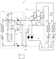
- FIG. 6 is a diagram for explaining the defrosting operation of the air conditioning apparatus 1 according to the first embodiment.
- the arrows indicate the direction of refrigerant flow.
- the control device 5 switches the outdoor flow path switching device 22 to a direction that connects the outdoor heat exchanger 23 and the accumulator 25.
- the control device 5 also closes the low pressure relay expansion valve 31 and closes the high pressure relay expansion valve 32.
- the control device 5 opens the low pressure valve 33 and opens the high pressure valve 34.
- the control device 5 then opens the indoor expansion valve 42 and opens the outdoor expansion valve 24. Note that the indoor expansion valve 42 may be closed.
- the refrigerant sucked into the compressor 21 is compressed by the compressor 21 and discharged in a high-temperature, high-pressure gas state.
- the high-temperature, high-pressure gas refrigerant discharged from the compressor 21 passes through the high-pressure main pipe 102 via the outdoor piping 115 equipped with a check valve 26b, and flows into the relay unit 3.
- the refrigerant that flows into the relay unit 3 passes through a part of the high-pressure liquid branch pipe 123, the high-pressure gas branch pipe 126 equipped with a high-pressure valve 34, the low-pressure gas branch pipe 125 equipped with a low-pressure valve 33, a part of the low-pressure liquid branch pipe 122, and the low-pressure main pipe 101, and flows back into the outdoor unit 2.
- the high-temperature, high-pressure gas refrigerant that flows into the outdoor unit 2 passes through the outdoor expansion valve 24 via the outdoor piping 114 equipped with a check valve 26c, where it is decompressed and expanded, becoming a high-temperature, low-pressure gas refrigerant, which passes through the outdoor heat exchanger 23.
- the high-temperature, low-pressure gaseous refrigerant passing through the outdoor heat exchanger 23 exchanges heat with the frost adhering to the outdoor heat exchanger 23, and becomes a low-temperature, low-pressure gaseous refrigerant.
- the outdoor heat exchanger 23 is defrosted.
- the low-temperature, low-pressure gaseous refrigerant then passes through the outdoor flow switching device 22 and the accumulator 25, and is again sucked into the compressor 21 and circulated. In this way, in the defrosting operation of the first embodiment, high-temperature refrigerant circulates between the outdoor unit 2 and the relay unit 3, and the flow of refrigerant to the indoor unit 44, and thus the supply of heat, is blocked.
- FIG. 7 is a flowchart showing the operation of the control device 5 according to the first embodiment.
- the execution of the defrosting operation will be described with reference to FIG. 7.
- the control device 5 determines whether or not defrosting of the outdoor heat exchanger 23 is necessary based on the measurement result of the frost detection device 27 (step S1). If it is determined that defrosting of the outdoor heat exchanger 23 is unnecessary (step S1: NO), the process of step S1 is repeated until it is determined that defrosting of the outdoor heat exchanger 23 is necessary. If it is determined that defrosting of the outdoor heat exchanger 23 is necessary (step S1: YES), the low-pressure valve 33 is changed to an open state (step S2). Then, the low-pressure relay expansion valve 31 is closed (step S3). This causes the operation mode to transition from the heating operation to the defrosting operation.
- step S4 determines whether the defrosting of the outdoor heat exchanger 23 has been completed based on the measurement result of the defrosting detection device 28 (step S4). If it is determined that the defrosting of the outdoor heat exchanger 23 is not completed (step S4: NO), the process of step S4 is repeated until it is determined that the defrosting of the outdoor heat exchanger 23 has been completed. If it is determined that the defrosting of the outdoor heat exchanger 23 has been completed (step S4: YES), the low-pressure relay expansion valve 31 is opened (step S5). Then, the low-pressure valve 33 is changed to a closed state (step S6). This causes the operation mode to transition from the defrosting operation to the heating operation.
- the air conditioning device 1 of the first embodiment controls the relay unit 3 to cut off the supply of heat to the indoor unit 4 during defrost operation, and controls the outdoor flow path switching device 22 to allow the refrigerant discharged from the compressor 21 to flow to the relay unit 3 without passing through the outdoor heat exchanger 23. Therefore, the outdoor unit 2, the relay unit 3, and the main pipe connecting the outdoor unit 2 and the relay unit 3 are prevented from dropping in temperature during defrost operation by circulating high-temperature refrigerant. In addition, the temperature of the indoor unit 4, in which refrigerant does not circulate, and the branch pipe connecting the relay unit 3 and the indoor unit 4 are also prevented from dropping during defrost operation.
- the air conditioning device 1 of the first embodiment it is not necessary to reheat the outdoor unit 2, the relay unit 3, the indoor unit 4, and the main pipe and branch pipe when heating is resumed, and the heating resume time from the end of the defrost operation to the start of actual heating in the room can be shortened.
- FIG. 8 is a refrigerant circuit diagram for explaining the defrosting operation of the air conditioner 1 according to the first modification of the first embodiment.
- the arrows indicate the direction of the refrigerant flow.
- the control device 5 switches the outdoor flow path switching device 22 to a direction that connects the outdoor heat exchanger 23 and the accumulator 25.
- the control device 5 opens the low pressure relay expansion valve 31 and opens the high pressure relay expansion valve 32.
- the control device 5 closes the low pressure valve 33 and opens the high pressure valve 34. Then, the control device 5 closes the indoor expansion valve 42 and opens the outdoor expansion valve 24.
- the refrigerant sucked into the compressor 21 is compressed by the compressor 21 and discharged in a high-temperature, high-pressure gas state.
- the high-temperature, high-pressure gas state refrigerant discharged from the compressor 21 passes through the high-pressure main pipe 102 via the outdoor piping 115 equipped with a check valve 26b, and flows into the relay unit 3.
- the refrigerant that flows into the relay unit 3 passes through the high-pressure liquid branch pipe 123 equipped with a high-pressure relay expansion valve 32, the low-pressure liquid branch pipe 122 equipped with a low-pressure relay expansion valve 31, and the low-pressure main pipe 101, and flows back into the outdoor unit 2.
- the high-temperature, high-pressure gas state refrigerant that flows into the outdoor unit 2 passes through the outdoor expansion valve 24 via the outdoor piping 114 equipped with a check valve 26c, where it is decompressed and expanded, becoming a high-temperature, low-pressure gas state refrigerant that passes through the outdoor heat exchanger 23.
- the high-temperature, low-pressure gaseous refrigerant passing through the outdoor heat exchanger 23 exchanges heat with the frost adhering to the outdoor heat exchanger 23, and becomes a low-temperature, low-pressure gaseous state. At this time, the outdoor heat exchanger 23 is defrosted.
- the low-temperature, low-pressure gaseous refrigerant then passes through the outdoor flow path switching device 22 and the accumulator 25, and is again sucked into the compressor 21 and circulated. In this way, even in the defrosting operation of the first modification of the first embodiment, high-temperature refrigerant circulates between the outdoor unit 2 and the relay unit 3, and the flow of refrigerant to the indoor unit 44, and the supply of heat, are blocked.
- FIG. 9 is a flowchart showing the operation of the control device 5 according to the first modification of the first embodiment.
- the execution of the defrosting operation will be described with reference to FIG. 9.
- the control device 5 determines whether or not defrosting of the outdoor heat exchanger 23 is necessary based on the measurement result of the frost detection device 27 (step S11). If it is determined that defrosting of the outdoor heat exchanger 23 is unnecessary (step S11: NO), the process of step S11 is repeated until it is determined that defrosting of the outdoor heat exchanger 23 is necessary. If it is determined that defrosting of the outdoor heat exchanger 23 is necessary (step S11: YES), the high-pressure relay expansion valve 32 is opened (step S12). Then, the indoor expansion valve 42 is closed (step S13). This causes the operation mode to transition from the heating operation to the defrosting operation.
- step S14 determines whether the defrosting of the outdoor heat exchanger 23 has been completed based on the measurement result of the defrosting detection device 28 (step S14). If it is determined that the defrosting of the outdoor heat exchanger 23 is not completed (step S14: NO), the process of step S14 is repeated until it is determined that the defrosting of the outdoor heat exchanger 23 has been completed. If it is determined that the defrosting of the outdoor heat exchanger 23 has been completed (step S14: YES), the indoor expansion valve 42 is opened (step S15). Then, the high-pressure relay expansion valve 32 is closed (step S16). This causes the operation mode to transition from the defrosting operation to the heating operation.
- the air conditioning apparatus 1 of Variation 1 of Embodiment 1 also controls the relay unit 3 to cut off the supply of heat to the indoor unit 4 during defrost operation, and controls the outdoor flow path switching device 22 to cause the refrigerant discharged from the compressor 21 to flow through the relay unit 3 without passing through the outdoor heat exchanger 23. Therefore, with the air conditioning apparatus 1 of Variation 1 of Embodiment 1, it does not take time to reheat the outdoor unit 2, relay unit 3, indoor unit 4, and main pipe and branch pipe when heating is resumed. Therefore, the heating restoration time from the end of defrost operation to the actual start of heating indoors can be shortened.
- the first high pressure valve 34a may be closed. Or, both the first indoor expansion valve 42a and the first high pressure valve 34a may be closed.
- the second high pressure valve 34b may be closed. Or, both the second indoor expansion valve 42b and the second high pressure valve 34b may be closed.
- the air conditioning apparatus 1 may control the devices differently from the devices in the defrosting operation shown in the first embodiment and the first modified example of the first embodiment.
- FIG. 10 is a refrigerant circuit diagram for explaining the defrosting operation of the air conditioning apparatus 1 according to the second modified example of the first embodiment.
- the arrows indicate the direction of the refrigerant flow.
- the control device 5 switches the outdoor flow path switching device 22 to a direction that connects the outdoor heat exchanger 23 and the accumulator 25.
- the control device 5 opens the low pressure relay expansion valve 31 and opens the high pressure relay expansion valve 32.
- the control device 5 opens the low pressure valve 33 and opens the high pressure valve 34. Then, the control device 5 closes the indoor expansion valve 42 and opens the outdoor expansion valve 24.
- a main circuit and a bypass circuit are formed.
- the refrigerant sucked into the compressor 21 is compressed by the compressor 21 and discharged in a high-temperature, high-pressure gas state.
- the high-temperature, high-pressure gas refrigerant discharged from the compressor 21 passes through the high-pressure main pipe 102 via the outdoor piping 115 provided with a check valve 26b, and flows into the relay unit 3.
- the refrigerant that flows into the relay unit 3 passes through a part of the high-pressure liquid branch pipe 123, the high-pressure gas branch pipe 126 provided with a high-pressure valve 34, the low-pressure gas branch pipe 125 provided with a low-pressure valve 33, a part of the low-pressure liquid branch pipe 122, and the low-pressure main pipe 101, and flows back into the outdoor unit 2.
- the high-temperature, high-pressure gas refrigerant that flows into the outdoor unit 2 passes through the outdoor expansion valve 24 via the outdoor piping 114 provided with a check valve 26c, is decompressed and expanded, and becomes a high-temperature, low-pressure gas refrigerant, which passes through the outdoor heat exchanger 23.
- the high-temperature, low-pressure gaseous refrigerant passing through the outdoor heat exchanger 23 exchanges heat with the frost adhering to the outdoor heat exchanger 23, and becomes a low-temperature, low-pressure gaseous refrigerant.
- the outdoor heat exchanger 23 is defrosted.
- the low-temperature, low-pressure gaseous refrigerant then passes through the outdoor flow switching device 22 and the accumulator 25, and is sucked back into the compressor 21 and circulated.
- the refrigerant flowing through the bypass circuit branches off from the main circuit, passes through high-pressure liquid branch pipe 123, in which high-pressure relay expansion valve 32 is provided, and low-pressure liquid branch pipe 122, in which low-pressure relay expansion valve 31 is provided, and merges into the main circuit.
- high-temperature refrigerant circulates between the outdoor unit 2 and the relay unit 3, and the flow of refrigerant to the indoor unit 44, and thus the supply of heat, is blocked.
- FIG. 11 is a flowchart showing the operation of the control device 5 according to the first modification of the first embodiment. The execution of the defrosting operation will be described based on FIG. 11.
- the control device 5 judges whether or not defrosting of the outdoor heat exchanger 23 is necessary based on the measurement result of the frost detection device 27 (step S21). If it is judged that defrosting of the outdoor heat exchanger 23 is unnecessary (step S21: NO), the process of step S21 is repeated until it is judged that defrosting of the outdoor heat exchanger 23 is necessary.
- step S21 If it is judged that defrosting of the outdoor heat exchanger 23 is necessary (step S21: YES), the low pressure valve 33 is changed to an open state and the high pressure relay expansion valve 32 is opened (step S22). Then, the indoor expansion valve 42 is closed (step S23). This causes the operation mode to transition from the heating operation to the defrosting operation.
- step S24 determines whether the defrosting of the outdoor heat exchanger 23 has been completed based on the measurement result of the defrosting detection device 28 (step S24). If it is determined that the defrosting of the outdoor heat exchanger 23 is not completed (step S24: NO), the process of step S24 is repeated until it is determined that the defrosting of the outdoor heat exchanger 23 has been completed. If it is determined that the defrosting of the outdoor heat exchanger 23 has been completed (step S24: YES), the indoor expansion valve 42 is opened (step S25). After that, the low pressure valve 33 is changed to a closed state, and the high pressure relay expansion valve 32 is closed (step S26). This causes the operation mode to transition from the defrosting operation to the heating operation.
- the air conditioning apparatus 1 of Variation 2 of Embodiment 1 also controls the relay unit 3 to cut off the supply of heat to the indoor unit 4 during defrost operation, and controls the outdoor flow path switching device 22 to cause the refrigerant discharged from the compressor 21 to flow through the relay unit 3 without passing through the outdoor heat exchanger 23. Therefore, with the air conditioning apparatus 1 of Variation 2 of Embodiment 1, no time is required to reheat the outdoor unit 2, relay unit 3, indoor unit 4, and main pipe and branch pipe when heating is resumed. Therefore, the heating restoration time from the end of defrost operation to the actual start of heating indoors can be shortened.
- the first low pressure valve 33a, the second low pressure valve 33b, and the high pressure relay expansion valve 32 may not all be opened, and only the high pressure relay expansion valve 32 or the first low pressure valve 33a and the second low pressure valve 33b may be opened.
- Embodiment 2 differs from the first embodiment in that the indoor refrigerant heat exchanger 41 is a device that exchanges heat between the heat medium and the air.
- the same parts as those in the first embodiment are denoted by the same reference numerals and the description thereof is omitted, and the description will be centered on the differences from the first embodiment.
- FIG. 12 is a refrigerant circuit diagram and a water circuit diagram of an air conditioning apparatus 10 according to embodiment 2.
- the configuration of the outdoor unit 2 is the same as that of embodiment 1, and therefore a description thereof is omitted.
- the relay unit 30 and the first indoor unit 40a are connected by a first high-pressure branch pipe 161a and a first low-pressure branch pipe 162a.
- the relay unit 30 and the second indoor unit 40b are connected by a second high-pressure branch pipe 161b and a second low-pressure branch pipe 162b.
- a heat medium flows through the first high-pressure branch pipe 161a and the second high-pressure branch pipe 161b, and the first low-pressure branch pipe 162a and the second low-pressure branch pipe 162b.
- the heat medium is a fluid other than a refrigerant, such as water or brine.
- the relay unit 30 has a high-pressure relay pipe 141, a low-pressure relay pipe 144, and a relay connection pipe 145.
- the relay unit 30 also has a first relay heat exchanger 301a, a second relay heat exchanger 301b, a first relay flow path switching device 302a, a second relay flow path switching device 302b, a first main expansion valve 303a, a second main expansion valve 303b, a sub-expansion valve 304, and a relay switching valve 305.
- the high-pressure relay pipe 141 is a pipe that connects the high-pressure main pipe 102 to the inlet and outlet of the first heat medium flow path 311a of the first relay heat exchanger 301a described later.
- the high-pressure relay pipe 141 also connects the high-pressure main pipe 102 to the inlet and outlet of the second heat medium flow path 311b of the second relay heat exchanger 301b described later.
- the high-pressure relay pipe 141 has an inlet branch pipe 142 that connects to the inlet, and an outlet branch pipe 143 that connects to the outlet.
- the inlet branch pipe 142 and the outlet branch pipe 143 are branched in correspondence with the first relay heat exchanger 301a and the second relay heat exchanger 301b.
- the low-pressure relay pipe 144 is a pipe that connects the low-pressure main pipe 101 to the outlet branch pipe 143.
- the first relay heat exchanger 301a has a first refrigerant flow path 310a through which the refrigerant that has been heat exchanged in the outdoor heat exchanger 23 flows, and a first heat medium flow path 311a through which the heat medium that has been heat exchanged in the indoor refrigerant heat exchanger 41 flows.
- the first relay heat exchanger 301a performs heat exchange between the refrigerant flowing in the first refrigerant flow path 310a and the heat medium flowing in the first heat medium flow path 311a.
- the second relay heat exchanger 301b has a second refrigerant flow path 310b through which the refrigerant that has been heat exchanged in the outdoor heat exchanger 23 flows, and a second heat medium flow path 311b through which the heat medium that has been heat exchanged in the indoor refrigerant heat exchanger 41 flows.
- the second relay heat exchanger 301b performs heat exchange between the refrigerant flowing in the second refrigerant flow path 310b and the heat medium flowing in the second heat medium flow path 311b.
- the first relay flow path switching device 302a switches between an orientation in which the first relay heat exchanger 301a is connected to the low-pressure main pipe 101 and an orientation in which the first relay heat exchanger 301a is connected to the high-pressure main pipe 102.
- the second relay flow path switching device 302b switches between an orientation in which the second relay heat exchanger 301b is connected to the low-pressure main pipe 101 and an orientation in which the second relay heat exchanger 301b is connected to the high-pressure main pipe 102.
- the first main expansion valve 303a is provided at a position corresponding to the first relay heat exchanger 301a in the outflow branch pipe 143 that branches into the first relay heat exchanger 301a and the second relay heat exchanger 301b.
- the first main expansion valve 303a is provided at a portion of the outflow branch pipe 143 that is closer to the first relay heat exchanger 301a than the connection portion of the low-pressure relay pipe 144.
- the first main expansion valve 303a reduces the pressure of the refrigerant flowing through the area of the outflow branch pipe 143 that corresponds to the first relay heat exchanger 301a and is, for example, an electronic expansion valve whose opening is adjustable.
- the second main expansion valve 303b is provided at a position corresponding to the second relay heat exchanger 301b in the outflow branch pipe 143 that branches into the first relay heat exchanger 301a and the second relay heat exchanger 301b.
- the second main expansion valve 303b is provided in a portion of the outflow branch pipe 143 that is closer to the second relay heat exchanger 301b than the connection portion of the low-pressure relay pipe 144.
- the second main expansion valve 303b reduces the pressure of the refrigerant flowing through the region of the outflow branch pipe 143 that corresponds to the second relay heat exchanger 301b, and expands it, and is, for example, an electronic expansion valve with an adjustable opening.
- the sub-expansion valve 304 is provided in the low-pressure relay pipe 144.
- the sub-expansion valve 304 reduces the pressure of the refrigerant flowing through the low-pressure relay pipe 144 and expands it, and is, for example, an electronic expansion valve with an adjustable opening.
- the relay switching valve 305 is provided in a portion of the outflow branch pipe 143 that is closer to the high-pressure main pipe 102 than the connection portion of the low-pressure relay pipe 144.
- the relay switching valve 305 has a function of switching between an open state that allows the flow of refrigerant through the outflow branch pipe 143 and a closed state that blocks the flow of refrigerant through the outflow branch pipe 143.
- the relay unit 30 has heat medium supply pipes 151 and 152, heat medium return pipes 153 and 154, and heat medium piping 155 to 158.
- the relay unit 30 also has a first pump 306a, a second pump 306b, a first mixed three-way valve 307a, a second mixed three-way valve 307b, a first diverting three-way valve 308a, and a second diverting three-way valve 308b.
- the heat medium supply pipe 151 is a pipe that connects the outlet of the first heat medium flow path 311a of the first relay heat exchanger 301a to the first mixed three-way valve 307a and the second mixed three-way valve 307b.
- the heat medium supply pipe 152 is a pipe that connects the outlet of the second heat medium flow path 311b of the second relay heat exchanger 301b to the first mixed three-way valve 307a and the second mixed three-way valve 307b.
- the heat medium return pipe 153 is a pipe that connects the inlet of the first heat medium flow path 311a of the first relay heat exchanger 301a to the first and second branch three-way valves 308a and 308b.
- the heat medium return pipe 154 is a pipe that connects the inlet of the second heat medium flow path 311b of the second relay heat exchanger 301b to the first and second branch three-way valves 308a and 308b.
- the heat medium pipe 155 is a pipe that connects the first mixed flow three-way valve 307a and the first high pressure branch pipe 161a.
- the heat medium pipe 156 is a pipe that connects the first diverted three-way valve 308a and the first low pressure branch pipe 162a.
- the heat medium pipe 157 is a pipe that connects the first mixed flow three-way valve 307a and the second high pressure branch pipe 161b.
- the heat medium pipe 158 is a pipe that connects the first diverted three-way valve 308a and the second low pressure branch pipe 162b.
- the first pump 306a is provided in the heat medium return pipe 153.
- the first pump 306a sends the heat medium flowing through the heat medium return pipe 153 to the first relay heat exchanger 301a side.
- the second pump 306b is provided in the heat medium return pipe 154.
- the second pump 306b sends the heat medium flowing through the heat medium return pipe 154 to the second relay heat exchanger 301b side.
- the first mixed flow three-way valve 307a is passed by the heat medium that flows out of the first relay heat exchanger 301a or the second relay heat exchanger 301b and flows to the first indoor unit 40a.
- the first mixed flow three-way valve 307a switches between a direction that connects the first indoor unit 40a and the first relay heat exchanger 301a and a direction that connects the first indoor unit 40a and the second relay heat exchanger 301b.
- the second mixed flow three-way valve 307b is passed by the heat medium that flows out of the first relay heat exchanger 301a or the second relay heat exchanger 301b and flows to the second indoor unit 40b.
- the second mixed flow three-way valve 307b switches between a direction that connects the second indoor unit 40b and the first relay heat exchanger 301a and a direction that connects the second indoor unit 40b and the second relay heat exchanger 301b.
- the first branch three-way valve 308a passes the heat medium that flows out from the first indoor unit 40a and flows to the first relay heat exchanger 301a or the second relay heat exchanger 301b.
- the first branch three-way valve 308a switches between a direction that connects the first indoor unit 40a and the first relay heat exchanger 301a and a direction that connects the first indoor unit 40a and the second relay heat exchanger 301b.
- the second branch three-way valve 308b passes the heat medium that flows out from the second indoor unit 40b and flows to the first relay heat exchanger 301a or the second relay heat exchanger 301b.
- the second branch three-way valve 308b switches between a direction that connects the second indoor unit 40b and the first relay heat exchanger 301a and a direction that connects the second indoor unit 40b and the second relay heat exchanger 301b.
- the first indoor unit 40a has a first indoor heat medium piping 171a.
- the first indoor unit 40a is equipped with a first indoor heat medium heat exchanger 401a.
- the first indoor refrigerant piping 131a connects the first high-pressure branch pipe 161a, the first indoor heat medium heat exchanger 401a, and the first low-pressure branch pipe 162a, and is a pipe through which a heat medium flows.
- the second indoor unit 40b has a second indoor heat medium piping 171b.
- the second indoor unit 40b is equipped with a second indoor heat medium heat exchanger 401b.
- the second indoor refrigerant piping 131b connects the second high-pressure branch pipe 161b, the second indoor heat medium heat exchanger 401b, and the second low-pressure branch pipe 162b, and is a pipe through which a heat medium flows.
- the first indoor heat medium heat exchanger 401a and the second indoor heat medium heat exchanger 401b exchange heat between the indoor air and the heat medium.
- the first indoor refrigerant heat exchanger 41a and the second indoor refrigerant heat exchanger 41b function as evaporators with a heat absorbing effect during cooling operation, and as condensers with a heat releasing effect during heating operation.
- the number of indoor units in the air conditioning device 10 is not limited to two, and may be one or three or more.
- the first indoor unit 40a and the second indoor unit 40b are not particularly distinguished, they and their corresponding configurations may be referred to as follows. That is, when the first indoor unit 40a and the second indoor unit 40b are not distinguished, they are referred to as indoor units 40.
- the first high-pressure branch pipe 161a and the second high-pressure branch pipe 161b are not distinguished, they are referred to as high-pressure branch pipe 161.
- the first low-pressure branch pipe 162a and the second low-pressure branch pipe 162b are not distinguished, they are referred to as low-pressure branch pipe 162.
- first relay heat exchanger 301a and the second relay heat exchanger 301b are not distinguished, they are referred to as relay heat exchanger 301.
- refrigerant flow path 310a and the second refrigerant flow path 310b are not distinguished, they are referred to as refrigerant flow path 310.
- the first heat medium flow path 311a and the second heat medium flow path 311b are not distinguished from each other, they are referred to as the heat medium flow path 311.
- the indoor heat medium heat exchanger 401a and the second indoor heat medium heat exchanger 401b are not distinguished from each other, they are referred to as the indoor heat medium heat exchanger 401.
- first relay flow path switching device 302a and the second relay flow path switching device 302b are not distinguished from each other, they are referred to as the relay flow path switching device 302.
- the first main expansion valve 303a and the second main expansion valve 303b are not distinguished from each other, they are referred to as the main expansion valve 303.
- the pump 306 When the first pump 306a and the second pump 306b are not distinguished from each other, they are referred to as the pump 306.
- the first mixed flow three-way valve 307a and the second mixed flow three-way valve 307b are not distinguished from each other, they are referred to as the mixed flow three-way valve 307.
- the diversion three-way valve 308a and 308b they are referred to as the diversion three-way valve 308.
- FIG. 13 is a functional block diagram showing an air conditioning apparatus 10 according to the second embodiment.
- the control device 5 controls the compressor 21, outdoor flow path switching device 22, and outdoor expansion valve 24 of the outdoor unit 2 according to the operation mode.
- the control device 5 also controls the relay flow path switching device 302, main expansion valve 303, and sub-expansion valve 304 of the relay unit 30, as well as the pump 306, mixed flow three-way valve 307, and divided flow three-way valve 308 according to the operation mode.
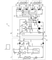
- FIG. 14 is a diagram for explaining the heating operation of the air conditioning device 10 according to the second embodiment.
- the solid arrows indicate the direction of the refrigerant flow
- the dashed arrows indicate the direction of the heat medium flow.
- the control device 5 switches the relay flow path switching device 302 to a direction that connects the relay heat exchanger 301 and the high-pressure main pipe 102.
- the control device 5 closes the relay switching valve 305.
- the control device 5 also opens the main expansion valve 303, opens the sub-expansion valve 304, and opens the outdoor expansion valve 24.
- the refrigerant sucked into the compressor 21 is compressed by the compressor 21 and discharged in a high-temperature, high-pressure gas state.
- the high-temperature, high-pressure gas refrigerant discharged from the compressor 21 passes through the high-pressure main pipe 102 via the outdoor pipe 115 provided with a check valve 26b, and flows into the relay unit 30.
- the refrigerant that flows into the relay unit 30 passes through the relay flow path switching device 302 and the refrigerant flow path 310 of the relay heat exchanger 301 via the inlet branch pipe 142.
- the refrigerant passing through the refrigerant flow path 310 of the relay heat exchanger 301 is cooled by heat exchange with the heat medium flowing through the heat medium flow path 311.
- the cooled refrigerant is decompressed and expanded by passing through a part of the outlet branch pipe 143 provided with the main expansion valve 303.
- the decompressed and expanded refrigerant passes through the low-pressure relay pipe 144 provided with the sub-expansion valve 304 and the low-pressure main pipe 101, and flows into the outdoor unit 2.
- the refrigerant that flows into the outdoor unit 2 passes through the outdoor expansion valve 24 via the outdoor piping 114 equipped with a check valve 26c, and is further decompressed and expanded before passing through the outdoor heat exchanger 23 that acts as an evaporator.
- the refrigerant that passes through the outdoor heat exchanger 23 exchanges heat with the outdoor air and evaporates and gasifies.
- the evaporated low-temperature, low-pressure gaseous refrigerant then passes through the outdoor flow switching device 22 and the accumulator 25, and is sucked back into the compressor 21 and circulated.
- the heat medium sent out from the pump 306 is heat exchanged with the refrigerant flowing through the refrigerant flow path 310 in the relay heat exchanger 301.
- the heat medium heated by the heat exchange passes through the high-pressure branch pipe 161 via the mixed flow three-way valve 307 and flows into the indoor unit 40.
- the heat medium that flows into the indoor unit 40 is cooled by heat exchange with the indoor air in the indoor heat medium heat exchanger 401. At this time, heating is performed indoors.
- the cooled refrigerant passes through the low-pressure branch pipe 162 and flows into the relay unit 30.
- the refrigerant that flows into the relay unit 30 passes through the diverting three-way valve 308, is sucked into the pump 306, and circulates.
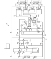
- FIG 15 is a diagram for explaining the defrosting operation of the air conditioning apparatus 10 according to the second embodiment.
- the arrows indicate the direction of refrigerant flow
- the dashed arrows indicate the direction of heat medium flow.
- the control device 5 switches the outdoor flow path switching device 22 to a direction that connects the outdoor heat exchanger 23 and the accumulator 25.
- the control device 5 switches the relay flow path switching device 302 to a direction that connects the relay heat exchanger 301 and the high-pressure main pipe 102.
- the control device 5 opens the relay switching valve 305.
- the control device 5 also closes the main expansion valve 303, opens the sub-expansion valve 304, and opens the outdoor expansion valve 24.
- the refrigerant sucked into the compressor 21 is compressed by the compressor 21 and discharged in a high-temperature, high-pressure gas state.
- the high-temperature, high-pressure gas state refrigerant discharged from the compressor 21 passes through the high-pressure main pipe 102 via the outdoor pipe 115 provided with a check valve 26b, and flows into the relay unit 30.
- the refrigerant that flows into the relay unit 30 passes through a part of the high-pressure relay pipe 141 provided with a relay switching valve 305, the low-pressure relay pipe 144 provided with a sub-expansion valve 304, and the low-pressure main pipe 101, and flows back into the outdoor unit 2.
- the high-temperature, high-pressure gas state refrigerant that flows into the outdoor unit 2 passes through the outdoor expansion valve 24 via the outdoor pipe 114 provided with a check valve 26c, is decompressed and expanded, and passes through the outdoor heat exchanger 23.
- the high-temperature, low-pressure gas state refrigerant that passes through the outdoor heat exchanger 23 is heat exchanged with the frost attached to the outdoor heat exchanger 23, and becomes a low-temperature, low-pressure gas state.
- the outdoor heat exchanger 23 is defrosted.
- the low-temperature, low-pressure gaseous refrigerant then passes through the outdoor flow switching device 22 and the accumulator 25, and is again drawn into the compressor 21 and circulated.
- the refrigerant does not flow through the relay heat exchanger 301, so heat is not supplied to the indoor unit 40.
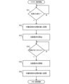
- FIG. 16 is a flowchart showing the operation of the control device 5 according to the second embodiment.
- the execution of the defrosting operation will be described with reference to FIG. 16.
- the control device 5 judges whether or not defrosting of the outdoor heat exchanger 23 is necessary based on the measurement result of the frost detection device 27 (step S31). If it is judged that defrosting of the outdoor heat exchanger 23 is unnecessary (step S31: NO), the process of step S31 is repeated until it is judged that defrosting of the outdoor heat exchanger 23 is necessary. If it is judged that defrosting of the outdoor heat exchanger 23 is necessary (step S31: YES), the relay switching valve 305 is changed to an open state (step S32). Then, the main expansion valve 303 is closed (step S33). This causes the operation mode to transition from the heating operation to the defrosting operation.
- step S34 determines whether the defrosting of the outdoor heat exchanger 23 has been completed based on the measurement result of the defrosting detection device 28 (step S34). If it is determined that the defrosting of the outdoor heat exchanger 23 is not completed (step S34: NO), the process of step S34 is repeated until it is determined that the defrosting of the outdoor heat exchanger 23 has been completed. If it is determined that the defrosting of the outdoor heat exchanger 23 has been completed (step S34: YES), the main expansion valve 303 is opened (step S35). Then, the relay switching valve 305 is changed to a closed state (step S36). This causes the operation mode to transition from the defrosting operation to the heating operation.
- the air conditioning device 10 of the second embodiment controls the relay unit 30 during defrost operation to cut off the supply of heat to the indoor unit 4, and controls the outdoor flow path switching device 22 to allow the refrigerant discharged from the compressor 21 to flow through the relay unit 30 without passing through the outdoor heat exchanger 23. Therefore, the outdoor unit 2, the relay unit 30, and the main pipe connecting the outdoor unit 2 and the relay unit 30 are prevented from dropping in temperature during defrost operation by circulating high-temperature refrigerant. In addition, the temperature of the indoor unit 40, in which refrigerant does not circulate, and the branch pipe connecting the relay unit 30 and the indoor unit 40 are also prevented from dropping during defrost operation.
- the air conditioning device 10 of the second embodiment it does not take time to reheat the outdoor unit 2, the relay unit 30, the indoor unit 40, and the main pipe and branch pipe when heating is resumed. Therefore, the heating resume time from the end of the defrost operation to the actual start of heating in the room can be shortened.
- Air conditioner 10 Air conditioner, 2 Outdoor unit, 3 Relay unit, 30 Relay unit, 4 Indoor unit, 40 Indoor unit, 4a First indoor unit, 4b Second indoor unit, 40a First indoor unit, 40b Second indoor unit, 5 Control device, 21 Compressor, 22 Outdoor flow path switching device, 23 Outdoor heat exchanger, 24 Outdoor expansion valve, 25 Accumulator, 2 6a check valve, 26b check valve, 26c check valve, 26d check valve, 27 frost detection device, 28 defrost detection device, 31 low pressure relay expansion valve, 32 high pressure relay expansion valve, 33 low pressure valve, 33a first low pressure valve, 33b second low pressure valve, 34 high pressure valve, 34a first high pressure valve, 34b second high pressure valve, 41 indoor refrigerant heat exchanger, 41a first indoor refrigerant medium heat exchanger, 41b second indoor refrigerant heat exchanger, 42 indoor expansion valve, 42a first indoor expansion valve, 42b second indoor expansion valve, 101 low pressure main pipe, 102 high pressure main pipe, 103 gas branch pipe, 103a first gas branch pipe,
Landscapes
- Engineering & Computer Science (AREA)
- Physics & Mathematics (AREA)
- Mechanical Engineering (AREA)
- Thermal Sciences (AREA)
- General Engineering & Computer Science (AREA)
- Compression-Type Refrigeration Machines With Reversible Cycles (AREA)
- Air Conditioning Control Device (AREA)
Priority Applications (2)
| Application Number | Priority Date | Filing Date | Title |
|---|---|---|---|
| PCT/JP2022/038341 WO2024079874A1 (ja) | 2022-10-14 | 2022-10-14 | 空気調和装置 |
| JP2023512095A JP7305081B1 (ja) | 2022-10-14 | 2022-10-14 | 空気調和装置 |
Applications Claiming Priority (1)
| Application Number | Priority Date | Filing Date | Title |
|---|---|---|---|
| PCT/JP2022/038341 WO2024079874A1 (ja) | 2022-10-14 | 2022-10-14 | 空気調和装置 |
Publications (1)
| Publication Number | Publication Date |
|---|---|
| WO2024079874A1 true WO2024079874A1 (ja) | 2024-04-18 |
Family
ID=87001936
Family Applications (1)
| Application Number | Title | Priority Date | Filing Date |
|---|---|---|---|
| PCT/JP2022/038341 Ceased WO2024079874A1 (ja) | 2022-10-14 | 2022-10-14 | 空気調和装置 |
Country Status (2)
| Country | Link |
|---|---|
| JP (1) | JP7305081B1 (https=) |
| WO (1) | WO2024079874A1 (https=) |
Citations (5)
| Publication number | Priority date | Publication date | Assignee | Title |
|---|---|---|---|---|
| JP2598550B2 (ja) * | 1990-04-23 | 1997-04-09 | 三菱電機株式会社 | 空気調和機 |
| WO2013088484A1 (ja) * | 2011-12-16 | 2013-06-20 | 三菱電機株式会社 | 空気調和装置 |
| WO2014128970A1 (ja) * | 2013-02-25 | 2014-08-28 | 三菱電機株式会社 | 空気調和装置 |
| WO2017199289A1 (ja) * | 2016-05-16 | 2017-11-23 | 三菱電機株式会社 | 空気調和装置 |
| WO2021001869A1 (ja) * | 2019-07-01 | 2021-01-07 | 三菱電機株式会社 | 空気調和装置 |
-
2022
- 2022-10-14 WO PCT/JP2022/038341 patent/WO2024079874A1/ja not_active Ceased
- 2022-10-14 JP JP2023512095A patent/JP7305081B1/ja active Active
Patent Citations (5)
| Publication number | Priority date | Publication date | Assignee | Title |
|---|---|---|---|---|
| JP2598550B2 (ja) * | 1990-04-23 | 1997-04-09 | 三菱電機株式会社 | 空気調和機 |
| WO2013088484A1 (ja) * | 2011-12-16 | 2013-06-20 | 三菱電機株式会社 | 空気調和装置 |
| WO2014128970A1 (ja) * | 2013-02-25 | 2014-08-28 | 三菱電機株式会社 | 空気調和装置 |
| WO2017199289A1 (ja) * | 2016-05-16 | 2017-11-23 | 三菱電機株式会社 | 空気調和装置 |
| WO2021001869A1 (ja) * | 2019-07-01 | 2021-01-07 | 三菱電機株式会社 | 空気調和装置 |
Also Published As
| Publication number | Publication date |
|---|---|
| JP7305081B1 (ja) | 2023-07-07 |
| JPWO2024079874A1 (https=) | 2024-04-18 |
Similar Documents
| Publication | Publication Date | Title |
|---|---|---|
| CN107110546B (zh) | 空气调节装置 | |
| US20080028773A1 (en) | Air conditioner and controlling method thereof | |
| WO2015045247A1 (ja) | ヒートポンプシステム、及び、ヒートポンプ式給湯器 | |
| JP2008082589A (ja) | 空気調和装置 | |
| JP2019020020A (ja) | 除湿送風機 | |
| JP3324420B2 (ja) | 冷凍装置 | |
| KR101692243B1 (ko) | 캐스캐이드 사이클을 이용한 히트 펌프 | |
| JP2004271105A (ja) | 冷凍サイクル装置 | |
| JP2667741B2 (ja) | 空気調和機 | |
| JP2002107012A (ja) | 空気調和機 | |
| WO2024079874A1 (ja) | 空気調和装置 | |
| JP3511161B2 (ja) | 空気調和装置 | |
| JP4270555B2 (ja) | 再熱除湿型空気調和機 | |
| JP2000291985A (ja) | 空気調和装置 | |
| JP3794339B2 (ja) | 空気調和機 | |
| JP7424425B1 (ja) | 二元冷凍装置 | |
| KR100591323B1 (ko) | 히트 펌프식 공기조화기 | |
| JPH076714B2 (ja) | 空気調和機 | |
| JP2004085047A (ja) | 空気調和装置 | |
| JP7802195B2 (ja) | 空気調和装置 | |
| KR100854828B1 (ko) | 공기조화 시스템의 제어방법 | |
| JPH1163709A (ja) | 空気調和機 | |
| JP6932551B2 (ja) | 熱交換システム及びその制御方法 | |
| KR20090021594A (ko) | 지속적인 난방운전이 가능한 히트펌프 공기조화기 | |
| WO2021192074A1 (ja) | 空気調和機 |
Legal Events
| Date | Code | Title | Description |
|---|---|---|---|
| ENP | Entry into the national phase |
Ref document number: 2023512095 Country of ref document: JP Kind code of ref document: A |
|
| 121 | Ep: the epo has been informed by wipo that ep was designated in this application |
Ref document number: 22962092 Country of ref document: EP Kind code of ref document: A1 |
|
| NENP | Non-entry into the national phase |
Ref country code: DE |
|
| 122 | Ep: pct application non-entry in european phase |
Ref document number: 22962092 Country of ref document: EP Kind code of ref document: A1 |