WO2024075709A1 - 軸受およびコンプレッサ - Google Patents
軸受およびコンプレッサ Download PDFInfo
- Publication number
- WO2024075709A1 WO2024075709A1 PCT/JP2023/035972 JP2023035972W WO2024075709A1 WO 2024075709 A1 WO2024075709 A1 WO 2024075709A1 JP 2023035972 W JP2023035972 W JP 2023035972W WO 2024075709 A1 WO2024075709 A1 WO 2024075709A1
- Authority
- WO
- WIPO (PCT)
- Prior art keywords
- bearing
- groove
- groove portion
- resin layer
- additive
- Prior art date
- Legal status (The legal status is an assumption and is not a legal conclusion. Google has not performed a legal analysis and makes no representation as to the accuracy of the status listed.)
- Ceased
Links
Images



Classifications
-
- F—MECHANICAL ENGINEERING; LIGHTING; HEATING; WEAPONS; BLASTING
- F16—ENGINEERING ELEMENTS AND UNITS; GENERAL MEASURES FOR PRODUCING AND MAINTAINING EFFECTIVE FUNCTIONING OF MACHINES OR INSTALLATIONS; THERMAL INSULATION IN GENERAL
- F16C—SHAFTS; FLEXIBLE SHAFTS; ELEMENTS OR CRANKSHAFT MECHANISMS; ROTARY BODIES OTHER THAN GEARING ELEMENTS; BEARINGS
- F16C33/00—Parts of bearings; Special methods for making bearings or parts thereof
- F16C33/02—Parts of sliding-contact bearings
- F16C33/04—Brasses; Bushes; Linings
- F16C33/20—Sliding surface consisting mainly of plastics
- F16C33/201—Composition of the plastic
-
- F—MECHANICAL ENGINEERING; LIGHTING; HEATING; WEAPONS; BLASTING
- F16—ENGINEERING ELEMENTS AND UNITS; GENERAL MEASURES FOR PRODUCING AND MAINTAINING EFFECTIVE FUNCTIONING OF MACHINES OR INSTALLATIONS; THERMAL INSULATION IN GENERAL
- F16C—SHAFTS; FLEXIBLE SHAFTS; ELEMENTS OR CRANKSHAFT MECHANISMS; ROTARY BODIES OTHER THAN GEARING ELEMENTS; BEARINGS
- F16C33/00—Parts of bearings; Special methods for making bearings or parts thereof
- F16C33/02—Parts of sliding-contact bearings
- F16C33/04—Brasses; Bushes; Linings
- F16C33/06—Sliding surface mainly made of metal
- F16C33/10—Construction relative to lubrication
-
- C—CHEMISTRY; METALLURGY
- C08—ORGANIC MACROMOLECULAR COMPOUNDS; THEIR PREPARATION OR CHEMICAL WORKING-UP; COMPOSITIONS BASED THEREON
- C08K—Use of inorganic or non-macromolecular organic substances as compounding ingredients
- C08K3/00—Use of inorganic substances as compounding ingredients
- C08K3/01—Use of inorganic substances as compounding ingredients characterized by their specific function
- C08K3/013—Fillers, pigments or reinforcing additives
-
- C—CHEMISTRY; METALLURGY
- C08—ORGANIC MACROMOLECULAR COMPOUNDS; THEIR PREPARATION OR CHEMICAL WORKING-UP; COMPOSITIONS BASED THEREON
- C08L—COMPOSITIONS OF MACROMOLECULAR COMPOUNDS
- C08L27/00—Compositions of homopolymers or copolymers of compounds having one or more unsaturated aliphatic radicals, each having only one carbon-to-carbon double bond, and at least one being terminated by a halogen; Compositions of derivatives of such polymers
- C08L27/02—Compositions of homopolymers or copolymers of compounds having one or more unsaturated aliphatic radicals, each having only one carbon-to-carbon double bond, and at least one being terminated by a halogen; Compositions of derivatives of such polymers not modified by chemical after-treatment
- C08L27/12—Compositions of homopolymers or copolymers of compounds having one or more unsaturated aliphatic radicals, each having only one carbon-to-carbon double bond, and at least one being terminated by a halogen; Compositions of derivatives of such polymers not modified by chemical after-treatment containing fluorine atoms
- C08L27/18—Homopolymers or copolymers or tetrafluoroethene
-
- C—CHEMISTRY; METALLURGY
- C09—DYES; PAINTS; POLISHES; NATURAL RESINS; ADHESIVES; COMPOSITIONS NOT OTHERWISE PROVIDED FOR; APPLICATIONS OF MATERIALS NOT OTHERWISE PROVIDED FOR
- C09D—COATING COMPOSITIONS, e.g. PAINTS, VARNISHES OR LACQUERS; FILLING PASTES; CHEMICAL PAINT OR INK REMOVERS; INKS; CORRECTING FLUIDS; WOODSTAINS; PASTES OR SOLIDS FOR COLOURING OR PRINTING; USE OF MATERIALS THEREFOR
- C09D179/00—Coating compositions based on macromolecular compounds obtained by reactions forming in the main chain of the macromolecule a linkage containing nitrogen, with or without oxygen, or carbon only, not provided for in groups C09D161/00 - C09D177/00
- C09D179/04—Polycondensates having nitrogen-containing heterocyclic rings in the main chain; Polyhydrazides; Polyamide acids or similar polyimide precursors
- C09D179/08—Polyimides; Polyester-imides; Polyamide-imides; Polyamide acids or similar polyimide precursors
-
- F—MECHANICAL ENGINEERING; LIGHTING; HEATING; WEAPONS; BLASTING
- F16—ENGINEERING ELEMENTS AND UNITS; GENERAL MEASURES FOR PRODUCING AND MAINTAINING EFFECTIVE FUNCTIONING OF MACHINES OR INSTALLATIONS; THERMAL INSULATION IN GENERAL
- F16C—SHAFTS; FLEXIBLE SHAFTS; ELEMENTS OR CRANKSHAFT MECHANISMS; ROTARY BODIES OTHER THAN GEARING ELEMENTS; BEARINGS
- F16C33/00—Parts of bearings; Special methods for making bearings or parts thereof
- F16C33/02—Parts of sliding-contact bearings
- F16C33/04—Brasses; Bushes; Linings
- F16C33/06—Sliding surface mainly made of metal
- F16C33/10—Construction relative to lubrication
- F16C33/1095—Construction relative to lubrication with solids as lubricant, e.g. dry coatings, powder
-
- F—MECHANICAL ENGINEERING; LIGHTING; HEATING; WEAPONS; BLASTING
- F16—ENGINEERING ELEMENTS AND UNITS; GENERAL MEASURES FOR PRODUCING AND MAINTAINING EFFECTIVE FUNCTIONING OF MACHINES OR INSTALLATIONS; THERMAL INSULATION IN GENERAL
- F16C—SHAFTS; FLEXIBLE SHAFTS; ELEMENTS OR CRANKSHAFT MECHANISMS; ROTARY BODIES OTHER THAN GEARING ELEMENTS; BEARINGS
- F16C33/00—Parts of bearings; Special methods for making bearings or parts thereof
- F16C33/02—Parts of sliding-contact bearings
- F16C33/04—Brasses; Bushes; Linings
- F16C33/20—Sliding surface consisting mainly of plastics
-
- F—MECHANICAL ENGINEERING; LIGHTING; HEATING; WEAPONS; BLASTING
- F16—ENGINEERING ELEMENTS AND UNITS; GENERAL MEASURES FOR PRODUCING AND MAINTAINING EFFECTIVE FUNCTIONING OF MACHINES OR INSTALLATIONS; THERMAL INSULATION IN GENERAL
- F16C—SHAFTS; FLEXIBLE SHAFTS; ELEMENTS OR CRANKSHAFT MECHANISMS; ROTARY BODIES OTHER THAN GEARING ELEMENTS; BEARINGS
- F16C33/00—Parts of bearings; Special methods for making bearings or parts thereof
- F16C33/02—Parts of sliding-contact bearings
- F16C33/04—Brasses; Bushes; Linings
- F16C33/20—Sliding surface consisting mainly of plastics
- F16C33/208—Methods of manufacture, e.g. shaping, applying coatings
-
- C—CHEMISTRY; METALLURGY
- C08—ORGANIC MACROMOLECULAR COMPOUNDS; THEIR PREPARATION OR CHEMICAL WORKING-UP; COMPOSITIONS BASED THEREON
- C08F—MACROMOLECULAR COMPOUNDS OBTAINED BY REACTIONS ONLY INVOLVING CARBON-TO-CARBON UNSATURATED BONDS
- C08F114/00—Homopolymers of compounds having one or more unsaturated aliphatic radicals, each having only one carbon-to-carbon double bond, and at least one being terminated by a halogen
- C08F114/18—Monomers containing fluorine
- C08F114/26—Tetrafluoroethene
-
- C—CHEMISTRY; METALLURGY
- C08—ORGANIC MACROMOLECULAR COMPOUNDS; THEIR PREPARATION OR CHEMICAL WORKING-UP; COMPOSITIONS BASED THEREON
- C08K—Use of inorganic or non-macromolecular organic substances as compounding ingredients
- C08K2201/00—Specific properties of additives
- C08K2201/002—Physical properties
- C08K2201/005—Additives being defined by their particle size in general
-
- C—CHEMISTRY; METALLURGY
- C08—ORGANIC MACROMOLECULAR COMPOUNDS; THEIR PREPARATION OR CHEMICAL WORKING-UP; COMPOSITIONS BASED THEREON
- C08K—Use of inorganic or non-macromolecular organic substances as compounding ingredients
- C08K3/00—Use of inorganic substances as compounding ingredients
- C08K3/02—Elements
- C08K3/04—Carbon
-
- C—CHEMISTRY; METALLURGY
- C08—ORGANIC MACROMOLECULAR COMPOUNDS; THEIR PREPARATION OR CHEMICAL WORKING-UP; COMPOSITIONS BASED THEREON
- C08K—Use of inorganic or non-macromolecular organic substances as compounding ingredients
- C08K3/00—Use of inorganic substances as compounding ingredients
- C08K3/34—Silicon-containing compounds
- C08K3/346—Clay
-
- C—CHEMISTRY; METALLURGY
- C08—ORGANIC MACROMOLECULAR COMPOUNDS; THEIR PREPARATION OR CHEMICAL WORKING-UP; COMPOSITIONS BASED THEREON
- C08L—COMPOSITIONS OF MACROMOLECULAR COMPOUNDS
- C08L2205/00—Polymer mixtures characterised by other features
- C08L2205/14—Polymer mixtures characterised by other features containing polymeric additives characterised by shape
- C08L2205/18—Spheres
-
- F—MECHANICAL ENGINEERING; LIGHTING; HEATING; WEAPONS; BLASTING
- F16—ENGINEERING ELEMENTS AND UNITS; GENERAL MEASURES FOR PRODUCING AND MAINTAINING EFFECTIVE FUNCTIONING OF MACHINES OR INSTALLATIONS; THERMAL INSULATION IN GENERAL
- F16C—SHAFTS; FLEXIBLE SHAFTS; ELEMENTS OR CRANKSHAFT MECHANISMS; ROTARY BODIES OTHER THAN GEARING ELEMENTS; BEARINGS
- F16C17/00—Sliding-contact bearings for exclusively rotary movement
- F16C17/02—Sliding-contact bearings for exclusively rotary movement for radial load only
-
- F—MECHANICAL ENGINEERING; LIGHTING; HEATING; WEAPONS; BLASTING
- F16—ENGINEERING ELEMENTS AND UNITS; GENERAL MEASURES FOR PRODUCING AND MAINTAINING EFFECTIVE FUNCTIONING OF MACHINES OR INSTALLATIONS; THERMAL INSULATION IN GENERAL
- F16C—SHAFTS; FLEXIBLE SHAFTS; ELEMENTS OR CRANKSHAFT MECHANISMS; ROTARY BODIES OTHER THAN GEARING ELEMENTS; BEARINGS
- F16C2202/00—Solid materials defined by their properties
- F16C2202/50—Lubricating properties
- F16C2202/52—Graphite
-
- F—MECHANICAL ENGINEERING; LIGHTING; HEATING; WEAPONS; BLASTING
- F16—ENGINEERING ELEMENTS AND UNITS; GENERAL MEASURES FOR PRODUCING AND MAINTAINING EFFECTIVE FUNCTIONING OF MACHINES OR INSTALLATIONS; THERMAL INSULATION IN GENERAL
- F16C—SHAFTS; FLEXIBLE SHAFTS; ELEMENTS OR CRANKSHAFT MECHANISMS; ROTARY BODIES OTHER THAN GEARING ELEMENTS; BEARINGS
- F16C2208/00—Plastics; Synthetic resins, e.g. rubbers
- F16C2208/02—Plastics; Synthetic resins, e.g. rubbers comprising fillers, fibres
-
- F—MECHANICAL ENGINEERING; LIGHTING; HEATING; WEAPONS; BLASTING
- F16—ENGINEERING ELEMENTS AND UNITS; GENERAL MEASURES FOR PRODUCING AND MAINTAINING EFFECTIVE FUNCTIONING OF MACHINES OR INSTALLATIONS; THERMAL INSULATION IN GENERAL
- F16C—SHAFTS; FLEXIBLE SHAFTS; ELEMENTS OR CRANKSHAFT MECHANISMS; ROTARY BODIES OTHER THAN GEARING ELEMENTS; BEARINGS
- F16C2208/00—Plastics; Synthetic resins, e.g. rubbers
- F16C2208/20—Thermoplastic resins
- F16C2208/30—Fluoropolymers
- F16C2208/32—Polytetrafluorethylene [PTFE]
-
- F—MECHANICAL ENGINEERING; LIGHTING; HEATING; WEAPONS; BLASTING
- F16—ENGINEERING ELEMENTS AND UNITS; GENERAL MEASURES FOR PRODUCING AND MAINTAINING EFFECTIVE FUNCTIONING OF MACHINES OR INSTALLATIONS; THERMAL INSULATION IN GENERAL
- F16C—SHAFTS; FLEXIBLE SHAFTS; ELEMENTS OR CRANKSHAFT MECHANISMS; ROTARY BODIES OTHER THAN GEARING ELEMENTS; BEARINGS
- F16C2240/00—Specified values or numerical ranges of parameters; Relations between them
- F16C2240/40—Linear dimensions, e.g. length, radius, thickness, gap
- F16C2240/60—Thickness, e.g. thickness of coatings
-
- F—MECHANICAL ENGINEERING; LIGHTING; HEATING; WEAPONS; BLASTING
- F16—ENGINEERING ELEMENTS AND UNITS; GENERAL MEASURES FOR PRODUCING AND MAINTAINING EFFECTIVE FUNCTIONING OF MACHINES OR INSTALLATIONS; THERMAL INSULATION IN GENERAL
- F16C—SHAFTS; FLEXIBLE SHAFTS; ELEMENTS OR CRANKSHAFT MECHANISMS; ROTARY BODIES OTHER THAN GEARING ELEMENTS; BEARINGS
- F16C2360/00—Engines or pumps
- F16C2360/42—Pumps with cylinders or pistons
Definitions
- the present invention relates to a bearing and a compressor.
- a configuration in which a groove is formed on the surface of the inner circumference of a cylindrical bearing is known.
- a configuration in which a groove is formed in a bearing layer on a substrate has been disclosed.
- a configuration in which a resin layer containing an additive such as graphite is used as the bearing layer provided on the substrate has been disclosed.
- the grooves are formed by, for example, cutting a resin material layer provided on the substrate.
- additives contained in the resin layer can make it difficult to form grooves in the desired shape. For this reason, conventional technology is unable to form grooves properly, resulting in insufficient seizure resistance.
- the present invention aims to provide a bearing and compressor that can improve seizure resistance.
- the bearing of the present invention comprises a cylindrical base material, a resin layer that is joined to the inner peripheral surface of the base material, has a plurality of grooves on the surface facing the shaft member housed on the inner peripheral surface side of the base material, the grooves being aligned in a direction intersecting the extension direction of the shaft member, and contains a synthetic resin and an additive dispersed in the synthetic resin, and the average particle size of the additive is less than the depth of the grooves.
- the present invention can improve seizure resistance.
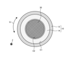
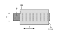
- FIG. 1A is an explanatory diagram of an example of the overall configuration of a bearing according to an embodiment.
- FIG. 1B is an explanatory diagram of an example of the overall configuration of a bearing according to an embodiment.
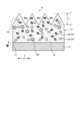
- FIG. 2 is an enlarged cross-sectional view of an example of a bearing.
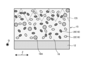
- FIG. 3A is an explanatory diagram of an example of a method for manufacturing a bearing.
- FIG. 3B is an explanatory diagram of an example of a method for manufacturing a bearing.
- FIG. 4 is an explanatory diagram of an example of a conventional comparative bearing.
- FIG. 5 is a schematic diagram of an example of a compressor.
- FIG. 6 is an explanatory diagram of the seizure resistance test.
- the bearing of this embodiment includes a cylindrical base material and a resin layer.
- the resin layer is bonded to the inner peripheral surface of the base material.
- the resin layer has a plurality of grooves on the surface facing the shaft member housed on the inner peripheral surface side of the base material, the grooves being aligned in a direction intersecting the extension direction of the shaft member.
- the resin layer includes a synthetic resin and an additive dispersed in the synthetic resin. The average particle size of the additive is less than the depth of the grooves.
- the average particle size of the additive contained in the resin layer is less than the depth of the groove. This makes it easier to form the groove in the bearing of this embodiment, and improves seizure resistance.
- the average particle size of the additives contained in the resin layer is greater than or equal to the depth of the groove, it may be difficult to form the groove in the desired shape. Also, if the average particle size of the additives contained in the resin layer is greater than or equal to the depth of the groove, the additives may fall off during processing of the groove, causing a large defect in the shape of the groove, and the groove may not be formed in the desired shape. If it becomes difficult to form the groove in the desired shape, it may be impossible to stably demonstrate bearing performance, including seizure resistance, and problems may arise with the quality of the bearing product. Also, if the average particle size of the additives contained in the resin layer is greater than or equal to the depth of the groove, it may be possible that the specified groove shape may not be maintained when sliding against the shaft member.
- the groove will be properly formed in the desired shape. It is also presumed that forming grooves in the desired shape will provide the grooves with an appropriate oil film retention capacity for the lubricating oil, improving lubrication performance and improving seizure resistance.
- FIG. 1A and 1B are explanatory diagrams of an example of the overall configuration of the bearing 10 of this embodiment.
- FIG. 1A is a cross-sectional view of the bearing 10 cut in a direction intersecting the extension direction Z of the bearing 10.
- FIG. 1B is an external view of the bearing 10 viewed from a direction intersecting the extension direction Z of the bearing 10.
- the bearing 10 comprises a base material 12 and a resin layer 14.
- the substrate 12 is a cylindrical member.
- the substrate 12 is described as a cylindrical member as an example. Note that the substrate 12 may be cylindrical, and is not limited to a cylindrical shape.
- the base material 12 is a member for housing the shaft member 30 on the side of the inner circumferential surface C1.
- the shaft member 30 is a rod-shaped member that is long in the extension direction Z.
- a form in which the extension direction Z of the base material 12 and the extension direction Z of the shaft member 30 coincide will be described as an example. Note that the extension direction Z of the base material 12 and the extension direction Z of the shaft member 30 may not coincide.
- the resin layer 14 is a layer that is bonded to the inner circumferential surface C1 of the substrate 12.
- a plurality of grooves MG are provided on the surface C2 of the resin layer 14 facing the shaft member 30 along a direction intersecting with the extension direction Z of the shaft member 30.
- Grooves MG along a direction intersecting with the extension direction Z means grooves MG that are extended along a direction intersecting with the extension direction Z.
- the groove portion MG may be provided along a direction intersecting the extension direction Z of the shaft member 30, either perpendicular to the extension direction Z or inclined at an angle of less than 90° to the perpendicular direction.
- the groove portion MG is provided along a direction perpendicular to the extension direction Z of the shaft member 30, i.e., along the circumferential direction Q of the cylindrical bearing 10.
- the groove portion MG may be formed in a continuous spiral shape from one end to the other end of the extension direction Z in the resin layer 14.
- the resin layer 14 may have a configuration in which multiple discontinuous groove portions MG are provided from one end to the other end of the extension direction Z.
- Figure 2 is an enlarged cross-sectional view of an example of a bearing 10.
- the bearing 10 is a laminate of a substrate 12 and a resin layer 14 formed on the substrate 12.
- the substrate 12 is a layer that provides mechanical strength to the bearing 10.
- the substrate 12 may be referred to as a backing metal or a backing metal layer.
- the substrate 12 may be, for example, a metal plate such as an Fe alloy, Cu, or Cu alloy.
- At least a portion of the region of the substrate 12 on the contact surface side with the resin layer 14 may be configured with a sintered layer.
- the sintered layer is a sintered body of metal powder, and is a porous layer having multiple holes.
- the metal powder that configures the sintered layer may be the same metal as the substrate 12, or may be a metal or material different from that of the substrate 12.
- the resin layer 14 is a layer that is bonded to the inner circumferential surface C1 of the base material 12. As described above, a groove portion MG is provided on the surface C2 of the resin layer 14 that faces the shaft member 30.
- the groove portion MG is a micro-level fine and precise groove processing portion formed on the surface of the resin layer 14.
- the groove portion MG may be called a micro groove or a micro groove.
- the shape of the groove portion MG is not limited.
- the groove portion MG may have any shape that can hold the lubricating oil supplied when the bearing 10 is rotated and can hold the oil between the groove portion MG and the shaft member 30.
- FIG. 2 shows an example in which the cross-sectional shape of the groove portion MG is V-shaped.
- the cross-sectional shape of the groove portion MG is not limited to a V-shape.
- the cross-sectional shape of the groove portion MG may be U-shaped, or may have a shape consisting of a flat bottom and a pair of side walls standing upright against the bottom, etc.
- the depth d of the groove MG and the width of the groove MG are not limited.
- the depth d and width of the groove MG may be any depth and width that can hold the lubricating oil supplied when the bearing 10 is rotated and driven, and can hold the oil between the groove MG and the shaft member 30.
- the depth d of the groove MG represents the distance in the thickness direction of the resin layer 14 between the bottom B of the groove MG and the apex T of the peak of the groove MG.
- the width of the groove MG represents the distance between the centers of the bottoms B of adjacent grooves MG.
- the depth d of the groove portion MG is, for example, in the range of 4.0 ⁇ m or more and 7.0 ⁇ m or less, but is not limited to this range.
- the width of the groove portion MG is, for example, in the range of 0.045 mm or more and 0.145 mm or less, preferably 0.075 mm or more and 0.095 mm or less, but is not limited to this range. Furthermore, the groove portion MG is formed continuously in the width direction.
- the resin layer 14 is a layer whose main component is a resin material.
- the resin layer 14 is composed of a synthetic resin 16 and an additive 18 dispersed in the synthetic resin 16.
- the composition of the synthetic resin 16 is not limited. From the viewpoint of improving abrasion resistance, it is preferable that the composition of the synthetic resin 16 is made of a heat-resistant resin.
- the synthetic resin 16 includes PTFE (polytetrafluoroethylene).
- PTFE polytetrafluoroethylene
- a form in which PTFE particles 16A, which are particulate PTFE, are dispersed in the synthetic resin 16 will be described as an example.
- the amount of PTFE particles 16A contained in synthetic resin 16 is not limited.
- the amount of PTFE particles 16A contained in synthetic resin 16 is preferably 5% by volume or more and 30% by volume or less, more preferably 10% by volume or more and 25% by volume or less, and particularly preferably 12% by volume or more and 20% by volume or less.
- the friction coefficient of the resin layer 14 can be reduced.
- the PTFE particles 16A have high heat resistance and are difficult to dissolve or decompose. Therefore, by making the synthetic resin 16 contain the PTFE particles 16A, the friction coefficient of the resin layer 14 can be effectively reduced. In other words, by containing the PTFE particles 16A, the seizure resistance of the bearing 10 can be further improved.
- the average particle size of the PTFE particles 16A is not limited.
- the average particle size of the PTFE particles 16A may be equal to or greater than the depth d of the groove portion MG, or may be less than the depth d of the groove portion MG.
- the average particle size of the PTFE particles 16A is preferably, for example, 1.0 ⁇ m or more and 25.0 ⁇ m or less, more preferably 1.0 ⁇ m or more and 15.0 ⁇ m or less, and particularly preferably 0.2 ⁇ m or more and 12.0 ⁇ m or less.
- the average particle size of the PTFE particles 16A is within the above range, the total surface area of the PTFE particles 16A dispersed in the synthetic resin 16 increases. Therefore, even if the content of the PTFE particles 16A is smaller within the above range, it is possible to reduce the friction coefficient of the resin layer 14 and improve the seizure resistance.
- the average particle size of the PTFE particles 16A refers to the average primary particle size of the PTFE particles 16A.
- the average primary particle size refers to the cumulative 50% particle size of the volume average particle size.
- a scanning electron microscope (SEM) can be used to measure the average particle size of the PTFE particles 16A.
- the PTFE particles 16A are observed by SEM observation at an appropriate magnification (for example, about 5000 times), the diameter of each of 100 primary particles is measured, the volume is calculated, and the cumulative 50% particle size can be regarded as the average primary particle size. Note that if the PTFE particles 16A are not spherical, the average of the major axis and minor axis is regarded as the diameter of the primary particle.
- the shape of the PTFE particles 16A is not limited.
- the shape of the PTFE particles 16A may be either spherical or elongated spheroid.
- the method of producing the PTFE particles 16A is not limited.
- the PTFE particles 16A may be any of PTFE particles produced by suspension polymerization, PTFE particles produced by emulsion polymerization, and recycled PTFE particles.
- the synthetic resin 16 may further include one or more selected from the group consisting of PI (polyimide), PAI (polyamideimide), PBI (polybenzimidazole), PA (polyamide), phenol, epoxy, POM (polyacetal), PEEK (polyetheretherketone), PE (polyethylene), PPS (polyphenylene sulfide) and PEI (polyetherimide).
- PI polyimide
- PAI polyamideimide
- PBI polybenzimidazole
- PA polyamide
- phenol epoxy
- POM polyacetal
- PEEK polyetheretherketone
- PE polyethylene
- PPS polyphenylene sulfide
- PEI polyetherimide
- the synthetic resin 16 may further contain a silane coupling agent to strengthen the bond with the additive 18.
- the additive 18 is a substance for improving the characteristics of the resin layer 14.
- the additive 18 means a substance other than resin. In other words, the additive 18 does not include resin.
- the average particle size of additive 18 in this embodiment is less than the depth d of groove portion MG.
- the average particle size of additive 18 must be less than 1 time the depth d of groove portion MG, preferably less than 3/4 times the depth d of groove portion MG, and more preferably less than 1/2 times the depth d of groove portion MG.
- the groove MG will be properly formed in the desired shape when bearing 10B is manufactured. By properly forming groove MG in the desired shape, it is believed that the groove MG will have a good ability to retain lubricant, and seizure resistance can be improved.
- the average particle size of the additives 18 may be measured by the following method. In detail, for example, a cross section of the resin layer 14 in the direction along the stretching direction Z is photographed using an electron microscope at an appropriate magnification (for example, 1000 times) to obtain an electron image. The area of the additives 18 contained in the obtained electron image is then measured for each type of additive 18 using a general image analysis method, and converted into an average diameter assuming a circle. By these processes, the average particle size for each type of additive 18 can be obtained.
- the additive 18 specifically includes at least one of graphite 20 and clay 22.
- the additive 18 contains graphite 20, which can improve the seizure resistance of the resin layer 14.
- the average particle size of additive 18 such as graphite 20 may be less than the depth d of groove portion MG.
- the depth d of groove portion MG is in the range of 4.0 ⁇ m or more and 7.0 ⁇ m or less.
- the average particle size of graphite 20 is, for example, preferably 1.0 ⁇ m or more and less than 4.0 ⁇ m, and more preferably 1.0 ⁇ m or more and less than 2.0 ⁇ m.
- the amount of graphite 20 contained in the synthetic resin 16 is not limited.
- the amount of graphite 20 contained in the synthetic resin 16 is preferably 1% by volume or more and less than 15% by volume, more preferably 3% by volume or more and less than 12% by volume, and particularly preferably 5% by volume or more and less than 9% by volume.
- the lipophilicity of the resin layer 14 can be improved, and seizure resistance can be further improved.
- the shape of the graphite 20 is not limited.
- the shape of the graphite 20 may be either flake-like or spherical. It is preferable that the shape of the graphite 20 is flake-like.
- Scaly means that the shape is scaly.
- Scaly graphite 20 is a crystal with a thickness in the C-axis direction perpendicular to the AB planes, where many AB planes (hexagonal mesh planes, basal planes) are stacked together as a result of carbon atoms forming a regular mesh structure, and the crystal has a thickness in the C-axis direction perpendicular to the AB planes.
- the bonding strength due to van der Waals forces between the stacked AB planes is much weaker than the bonding strength in the in-plane direction of the AB planes, so shear is likely to occur between the AB planes. For this reason, the thickness of the flake graphite 20 in the stacking direction is thin compared to the spread of the AB planes, and it is generally thin plate-like.
- flake graphite 20 When the flake graphite 20 is subjected to an external force, shear occurs between the A and B planes, and the flake graphite 20 functions as a solid lubricant. Therefore, by using flake graphite 20 as the graphite 20 dispersed in the synthetic resin 16, it is possible to further improve the seizure resistance of the resin layer 14.
- the graphitization degree of the graphite 20 is high.
- the graphitization degree of the graphite 20 is preferably 95% or more, and more preferably 99% or more.
- the clay 22 is generally an Al 2 O 3 —SiO 2 —H 2 O clay mineral.
- the clay 22 may be a calcined clay.
- the additive 18 contains the clay 22, the abrasion resistance of the resin layer 14 can be improved.
- the average particle size of the clay 22 may be less than the depth d of the groove portion MG.
- the depth d of the groove portion MG is in the range of 4.0 ⁇ m or more and 7.0 ⁇ m or less.
- the average particle size of the clay 22 is preferably, for example, 2.0 ⁇ m or more and 4.0 ⁇ m or less, and more preferably 2.0 ⁇ m or more and less than 3.5 ⁇ m.
- the amount of clay 22 contained in synthetic resin 16 is not limited.
- the amount of clay 22 contained in synthetic resin 16 is preferably, for example, 1% by volume or more and 5% by volume or less, and more preferably 1% by volume or more and 3% by volume or less. When the amount of clay 22 is within the above range, it is possible to improve the abrasion resistance of resin layer 14 and suppress the decrease in fatigue resistance.
- the bearing 10 of this embodiment is manufactured, for example, by the following process.
- FIGS. 3A and 3B are explanatory diagrams of an example of a method for manufacturing bearing 10.
- the constituent material of the resin layer 14 having the above-mentioned structure is applied onto the substrate 12 to form a resin material layer 15 (resin material layer forming process). Then, the resin material layer 15 formed on the substrate 12 is dried.
- Known conditions may be used as the application and drying conditions.
- a groove processing step is performed.
- the cutting edge of a cutting tool is moved along the surface of the resin material layer 15, and the surface of the resin material layer 15 is scraped away along the cut surface CS of the groove MG of the desired shape.
- This groove processing step produces a bearing 10 having a resin layer 14 with a groove MG formed therein, as shown in FIG. 3B.
- the formation of the groove portion MG is not limited to cutting the resin material layer 15 with a cutting tool.
- the groove portion MG may be formed by etching, a roller, etc.
- the resin material layer 15 contains additive 18.
- the average particle size of the additive 18 is less than the depth d of the groove portion MG. Therefore, in this embodiment, even if the resin material layer 15 contains additive 18, the groove portion MG can be easily formed.
- the additive 18 may fall off from the resin layer 14 due to cutting of the resin material layer 15, etc., and a fallen portion F may be formed on the surface of the resin layer 14 (see FIG. 3B).
- the average particle size of the additive 18 is less than the depth d of the groove portion MG. Therefore, even if a fallen portion F is formed on the surface of the resin layer 14 due to the additive 18 falling off when the groove portion MG is formed, the shape of the groove portion MG in the bearing 10 of this embodiment will be in a state where the target shape is substantially maintained (see FIG. 3B). In other words, in this embodiment, it is possible to manufacture a bearing 10 having a groove portion MG with a reduced shape defect rate (i.e., normal) with respect to the target shape.
- Figure 4 is an explanatory diagram of an example of a comparative bearing 1000.
- the average particle size of additives 19 such as graphite 21 and clay 23 dispersed in the synthetic resin 16 of the comparative resin layer 17 is equal to or greater than the depth d of the groove MG.
- the relative size of additives 19 to the groove MG is large, which can make it difficult to process the groove MG on the surface of the resin material layer of the comparative resin layer 17.
- the relative size of the detached portion F formed by the additive 19 falling off during the formation of the groove portion MG was large in comparison to the groove portion MG, and as a result, there were cases in which the groove portion MG was formed with a shape that was significantly deformed from the intended shape (see Figure 4). For this reason, the comparative bearing 1000 was unable to form a normal groove portion MG, and it was considered difficult to achieve stable bearing performance, resulting in quality problems as a bearing product.
- the average particle size of the additive 18 is less than the depth d of the groove portion MG. Therefore, in this embodiment, even if the resin material layer 15 contains the additive 18, the groove portion MG can be easily formed. Also, as shown in FIG. 3B, the bearing 10 of this embodiment has a smaller shape defect rate for the target shape of the groove portion MG compared to the conventional comparative bearing 1000, and it is believed that it is possible to manufacture a bearing 10 with a groove portion MG that is closer to or matches the target shape.
- the groove portion MG by forming the groove portion MG in the desired shape, it is believed that the groove portion MG can provide an appropriate lubricant retention force, thereby improving the seizure resistance of the bearing 10.
- the bearing 10 is used, for example, as a bushing in a fuel injection pump, various bearings, a compressor, or the like.
- FIG. 5 is a schematic diagram of an example of a compressor 40.
- the compressor 40 is an example of an application form of the bearing 10.
- FIG. 5 shows a scroll compressor as an example. Scroll compressors are used to compress gases such as refrigerant gas in air conditioners for automobiles, homes, railways, or businesses, for example.
- the compressor 40 has a cylindrical housing 41 with both ends closed.
- the center of the housing 41 is disposed along the z-axis.
- the z-axis direction coincides with a direction parallel to the vertical direction.
- the +z direction is the vertical direction, and is sometimes referred to as the upward direction.
- the -z direction is the anti-vertical direction, and is sometimes referred to as the downward direction.
- FIG. 5 shows an example in which the extension direction Z of the shaft member 30 and the bearing 10 coincides with the z axis direction, which is parallel to the vertical direction.
- FIG. 5 explains an example in which the compressor 40 is a vertical compressor.
- a fixed scroll member 47 with spiral blades is fixed to the upper part of the housing 41 of the compressor 40.
- a movable scroll member 48 with spiral blades that wind in the opposite direction to the blades of the fixed scroll member 47 is disposed below the fixed scroll member 47, facing the fixed scroll member 47.
- the movable scroll member 48 forms a compression chamber together with the fixed scroll member 47.
- the shaft member 30 has the crank pin 30A at the top.
- the crank pin 30A rotates.
- the crank pin 30A is housed in a pin receiver 48A provided on the lower side of the movable scroll member 48, and rotates the movable scroll member 48 by rotating itself.
- the compressor 40 air conditioner compressor
- the compressor 40 that compresses the refrigerant contains lubricating oil (refrigeration oil) in the refrigerant, and supplies the lubricating oil to each bearing 10 by circulating the refrigerant.
- lubricating oil refrigeration oil
- the compressor is stopped, the refrigerant is not circulating, so no lubricating oil is supplied. Therefore, from the time the compressor is stopped until the beginning of startup, the bearing 10 is lubricated only by the oil held (adhered) between the bearing 10 and the shaft member 30.
- the shaft member 30 When the compressor 40 starts, the shaft member 30 is driven to rotate by lubricating it with the oil held between the bearing 10 and the shaft member 30. If this oil runs out before the refrigerant circulates, seizure will occur.
- a groove portion MG is provided on the surface C2 of the resin layer 14 facing the shaft member 30.
- the groove MG provided in the resin layer 14 increases the oil retention of the lubricating oil that has entered the gap between the bearing 10 and the shaft member 30.
- the resin layer 14 of the bearing 10 and the shaft member 30 are lubricated, which is thought to prevent the shaft member 30 from running out of oil and seizing when the shaft member 30 first starts rotating.
- the compressor 40 equipped with the bearing 10 of this embodiment can improve seizure resistance.
- FIG. 5 shows an example in which the compressor 40 is a vertical compressor.
- the compressor 40 may be a horizontal compressor in which the extension direction Z of the shaft member 30 and the bearing 10 is aligned with the horizontal direction.
- the compressor 40 may also be in a form in which the extension direction Z of the shaft member 30 and the bearing 10 is aligned with the horizontal direction and intersects with both the horizontal and vertical directions.
- the timing of forming the groove portion MG is not limited.
- the groove portion MG may be formed before the bearing 10 is attached to the compressor 40.
- the compressor 40 may be manufactured by attaching the bearing 10 with the groove portion MG formed therein to the compressor 40.
- the groove portion MG may be formed by performing a groove processing process on the resin material layer 15 after mounting the bearing 10 having the resin material layer 15 without the groove portion MG formed therein to the compressor 40.
- the average particle size of the additive 18 contained in the resin material layer 15 is less than the depth d of the groove portion MG to be formed. Therefore, in this embodiment, even if the resin material layer 15 contains the additive 18, the groove portion MG can be easily formed. That is, in this embodiment, even if the groove portion MG is formed after the bearing 10 is mounted to the compressor 40, the groove portion MG of the desired shape can be easily and highly accurately formed.
- Test pieces having the following resin layer 14 and comparative resin layer were prepared, and the seizure resistance of these test pieces was evaluated.
- a steel plate (SPCC (JIS)) having a thickness of 1.5 mm was prepared as the substrate 12.
- a solution of the constituent material of the resin layer 14 was prepared by adding the additives shown in Examples 1 to 3 of Table 1 to the synthetic resin having the composition shown in Examples 1 to 3 of Table 1. Then, this solution was applied to the substrate 12 by a knife coating method. After application, the solution was dried for 60 to 90 minutes at room temperature to about 200°C. Then, the temperature was raised to about 300°C and the resin was baked for 30 to 90 minutes. Through these steps, a resin material layer 15 was formed on the substrate 12.
- the cutting edge of the cutting tool was moved along the surface of the resin material layer 15, and the surface of the resin material layer 15 was scraped off along the cut surface CS of the groove portion MG of the target shape.
- the target shape was a depth d of 4.0 ⁇ m, a width of 0.075 ⁇ m, and a V-shaped cross section.
- test pieces of the resin layer 14 of each of Examples 1 to 3 were produced.
- test pieces of comparative resin layers 17 of Comparative Examples 1 to 3 were prepared in the same manner as resin layers 14 of Examples 1 to 3, except that the synthetic resins and additives shown in Comparative Examples 1 to 3 in Table 1 were used as the constituent materials of comparative resin layers 17.
- the graphite used was flake - like graphite with a graphitization degree of 99%, and the clay used had the structural formula Al2O3.2SiO2 .
- Figure 6 is an explanatory diagram of the seizure resistance test.
- the groove portion MG side of a test piece corresponding to either the resin layer 14 or the comparative resin layer 17 was placed facing the shaft member 30, and 45 mg of lubricating oil was applied to the surface on the groove portion MG side.
- the shaft member 30 was then rotated while applying a load to evaluate the seizure resistance. The evaluation was performed under the following conditions.
- Testing machine Seizure testing machine (see Figure 6) Load: 5 MPa Rotational speed (circumferential speed): 2 m/s Test temperature (ambient temperature): 40°C Material of shaft member 30: SCM415 (Hv500 or more) Surface roughness Ra of the shaft member 30: 0.15 ⁇ m
- Lubricating oil liquid paraffin (viscosity: 4.4 ⁇ 10 ⁇ 3 Pa ⁇ s)
- Lubrication method Lubricant application 45mg ⁇ Oil clearance: 100 ⁇ m Seizure judgment: the time (seconds) required from the start of rotation of the shaft member 30 until the friction torque reaches 4.8 N ⁇ m
- the shaft member 30 was rotated under the above conditions, and the time (seconds) required from the start of rotational drive of the shaft member 30 until the friction torque reached 4.8 Nm was measured as the elapsed time until seizure.
- the elapsed time until seizure means the time required from the start of rotational drive of the shaft member 30 until seizure occurs.
- Table 1 the longer the elapsed time until seizure, the higher the seizure resistance, i.e., the more excellent the seizure resistance.
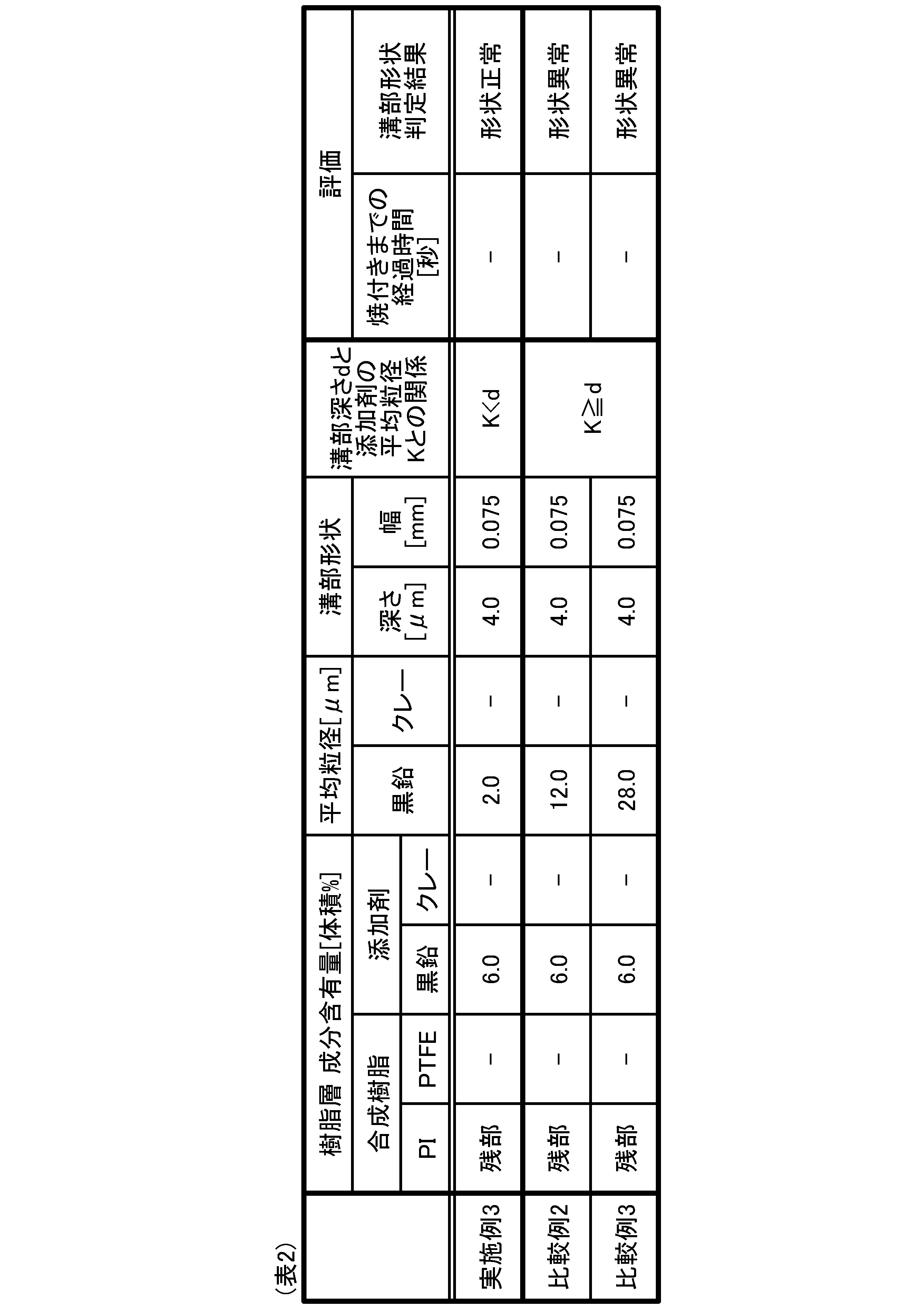
- the shape defect rate of the groove shape was small (shape normal). Also, as shown in Table 2, when the Gr grain size was larger than the depth of the groove MG, the shape defect rate of the groove shape was large (shape abnormal).
- the surfaces of the groove portions MG of the bearing 10 and the comparative bearing 1000 were traced along the extension direction Z with a roughness measuring device (SE-3400 manufactured by Kosaka Laboratory) to obtain surface shape expansion curves along the extension direction Z of the groove portions MG. Then, for each of the test specimens of the example and the test specimen of the comparative example, the average value av of the depths d of the multiple groove portions MG included in the surface shape expansion curves and the standard deviation ⁇ of the depths d of the groove portions MG were calculated.
- SE-3400 manufactured by Kosaka Laboratory
- groove portions MG with a depth d within the range of the standard deviation ⁇ 1/2 from the average value av were determined to be normal, and groove portions MG with a depth d outside the range were determined to be defective. Then, for each of the test pieces of the examples and the test pieces of the comparative examples, if the ratio of groove portions MG determined to be defective among the multiple groove portions MG included was 20% or more, the groove portions MG were determined to have an abnormal shape.
- the resin layer 14 according to the present invention may further contain unavoidable impurities.
- the specific structure of the bearing 10 is not limited to those exemplified in Figures 1A to 2, etc.
Landscapes
- Engineering & Computer Science (AREA)
- General Engineering & Computer Science (AREA)
- Chemical & Material Sciences (AREA)
- Mechanical Engineering (AREA)
- Chemical Kinetics & Catalysis (AREA)
- Organic Chemistry (AREA)
- Medicinal Chemistry (AREA)
- Polymers & Plastics (AREA)
- Health & Medical Sciences (AREA)
- Manufacturing & Machinery (AREA)
- Life Sciences & Earth Sciences (AREA)
- Materials Engineering (AREA)
- Wood Science & Technology (AREA)
- Sliding-Contact Bearings (AREA)
- Compositions Of Macromolecular Compounds (AREA)
Abstract
Description
本実施の形態の軸受10は、例えば、下記工程によって作製される。
次に、軸受10の適用形態の一例を説明する。軸受10は、例えば燃料噴射ポンプにおけるブシュ、各種の軸受、またはコンプレッサなどとして用いられる。
基材12として、厚さ1.5mmの鋼板(SPCC(JIS))を用意した。また、表1の実施例1~実施例3に示す組成の合成樹脂に、表1の実施例1~実施例3に示す添加剤を添加した樹脂層14の構成材料の溶液を調整した。そして、この溶液を、基材12上にナイフコート法により塗布した。塗布後、室温~約200℃の範囲で60分~90分乾燥した。その後、約300℃まで昇温し、30分~90分焼成した。これらの工程により、基材12上に樹脂材料層15を形成した。さらに、樹脂材料層15の表面に沿って切削工具の刃先を移動させることで、樹脂材料層15の表面を目的形状の溝部MGの切断面CSに沿って削り取った。目的形状は、溝部MGの深さd4.0μm、溝部MGの幅0.075μm、断面形状V字状とした。

―耐焼付き性―
実施例の試験片および比較例の試験片について、耐焼付き性を評価した。耐焼付き性の評価は、図6に示す試験機を用いて行った。
・荷重:5Mpa
・回転速度(周速):2m/s
・試験温度(雰囲気温度):40℃
・軸部材30の材質:SCM415(Hv500以上)
・軸部材30の表面粗さRa:0.15μm
・潤滑油:流動パラフィン(粘度:4.4×10⁻³Pa・s)
・潤滑方法:潤滑油の塗布 45mg
・オイルクリアランス:100μm
・焼付き判定:軸部材30の回転駆動開始から摩擦トルクが4.8N・mとなるまでに要する時間(秒)
表1に示すように、溝部MGを付けた実施例の試験片は全て、比較例の溝部MGの無い試験片に比べて焼き付きまでの経過時間が長かった。このため、実施例の樹脂層14の試験片は、比較例の比較樹脂層17の試験片に比べて、耐焼付き性が高いという評価結果が得られた。
実施例の試験片および比較例の試験片について、溝部MGの形状加工性を評価した。評価結果を表2に示した。
12 基材
14 樹脂層
16 合成樹脂
16A PTFE粒子
18 添加剤
20 黒鉛
22 クレー
40 コンプレッサ
Claims (5)
- 筒状の基材と、
前記基材の内周面に接合し、前記基材の前記内周面の側に収容される軸部材との対向面側の表面に前記軸部材の延伸方向に対して交差する方向に沿った複数の溝部が設けられ、合成樹脂および前記合成樹脂中に分散された添加剤を含む樹脂層と、
を備え、
前記添加剤の平均粒径が、前記溝部の深さ未満である、
軸受。 - 前記添加剤は、
黒鉛およびクレーの少なくとも一方を含む、
請求項1に記載の軸受。 - 前記黒鉛の平均粒径が1.0μm以上4.0μm未満であり、
前記クレーの平均粒径が2.0μm以上3.5μm未満であり、
前記溝部の深さが4μm以上7μm以下である、
請求項2に記載の軸受。 - 前記合成樹脂は、PTFE粒子を含む、
請求項1に記載の軸受。 - 請求項1に記載の軸受を備えたコンプレッサ。
Priority Applications (3)
| Application Number | Priority Date | Filing Date | Title |
|---|---|---|---|
| DE112023003369.2T DE112023003369T5 (de) | 2022-10-05 | 2023-10-02 | Lager und kompressor |
| KR1020257011013A KR20250059507A (ko) | 2022-10-05 | 2023-10-02 | 베어링 및 컴프레서 |
| CN202380070679.9A CN119998553A (zh) | 2022-10-05 | 2023-10-02 | 轴承和压缩机 |
Applications Claiming Priority (2)
| Application Number | Priority Date | Filing Date | Title |
|---|---|---|---|
| JP2022-161275 | 2022-10-05 | ||
| JP2022161275A JP7727610B2 (ja) | 2022-10-05 | 2022-10-05 | 軸受およびコンプレッサ |
Publications (1)
| Publication Number | Publication Date |
|---|---|
| WO2024075709A1 true WO2024075709A1 (ja) | 2024-04-11 |
Family
ID=90608178
Family Applications (1)
| Application Number | Title | Priority Date | Filing Date |
|---|---|---|---|
| PCT/JP2023/035972 Ceased WO2024075709A1 (ja) | 2022-10-05 | 2023-10-02 | 軸受およびコンプレッサ |
Country Status (5)
| Country | Link |
|---|---|
| JP (1) | JP7727610B2 (ja) |
| KR (1) | KR20250059507A (ja) |
| CN (1) | CN119998553A (ja) |
| DE (1) | DE112023003369T5 (ja) |
| WO (1) | WO2024075709A1 (ja) |
Citations (5)
| Publication number | Priority date | Publication date | Assignee | Title |
|---|---|---|---|---|
| JP2008069973A (ja) * | 2006-09-14 | 2008-03-27 | Federal-Mogul Deva Gmbh | プラスチックの滑り層およびこの滑り層を有する滑り要素 |
| JP2008208902A (ja) * | 2007-02-26 | 2008-09-11 | Alps Electric Co Ltd | プリンタの軸受機構 |
| JP2010084825A (ja) * | 2008-09-30 | 2010-04-15 | Ntn Corp | 流体動圧軸受装置及びその製造方法 |
| JP2018193519A (ja) * | 2017-05-22 | 2018-12-06 | 大豊工業株式会社 | 摺動部材用樹脂材料及び摺動部材 |
| JP2021084962A (ja) * | 2019-11-27 | 2021-06-03 | 大豊工業株式会社 | 摺動部材用樹脂材料および摺動部材 |
Family Cites Families (1)
| Publication number | Priority date | Publication date | Assignee | Title |
|---|---|---|---|---|
| JP6944811B2 (ja) | 2017-05-22 | 2021-10-06 | 大豊工業株式会社 | 摺動部材用樹脂材料及び摺動部材 |
-
2022
- 2022-10-05 JP JP2022161275A patent/JP7727610B2/ja active Active
-
2023
- 2023-10-02 CN CN202380070679.9A patent/CN119998553A/zh active Pending
- 2023-10-02 KR KR1020257011013A patent/KR20250059507A/ko active Pending
- 2023-10-02 DE DE112023003369.2T patent/DE112023003369T5/de active Pending
- 2023-10-02 WO PCT/JP2023/035972 patent/WO2024075709A1/ja not_active Ceased
Patent Citations (5)
| Publication number | Priority date | Publication date | Assignee | Title |
|---|---|---|---|---|
| JP2008069973A (ja) * | 2006-09-14 | 2008-03-27 | Federal-Mogul Deva Gmbh | プラスチックの滑り層およびこの滑り層を有する滑り要素 |
| JP2008208902A (ja) * | 2007-02-26 | 2008-09-11 | Alps Electric Co Ltd | プリンタの軸受機構 |
| JP2010084825A (ja) * | 2008-09-30 | 2010-04-15 | Ntn Corp | 流体動圧軸受装置及びその製造方法 |
| JP2018193519A (ja) * | 2017-05-22 | 2018-12-06 | 大豊工業株式会社 | 摺動部材用樹脂材料及び摺動部材 |
| JP2021084962A (ja) * | 2019-11-27 | 2021-06-03 | 大豊工業株式会社 | 摺動部材用樹脂材料および摺動部材 |
Also Published As
| Publication number | Publication date |
|---|---|
| CN119998553A (zh) | 2025-05-13 |
| DE112023003369T5 (de) | 2025-07-31 |
| JP7727610B2 (ja) | 2025-08-21 |
| JP2024054795A (ja) | 2024-04-17 |
| KR20250059507A (ko) | 2025-05-02 |
Similar Documents
| Publication | Publication Date | Title |
|---|---|---|
| CN103890403B (zh) | 涡旋式压缩机 | |
| EP2995827A1 (en) | Sliding member | |
| AU2006223991B2 (en) | Composition for sliding element, sliding element and fluid machine | |
| CN108380883B (zh) | 通过松散烧结获得的具有超低孔隙率的轴承材料及其制造方法 | |
| JP7727610B2 (ja) | 軸受およびコンプレッサ | |
| JP7149252B2 (ja) | 摺動部材用樹脂材料および摺動部材 | |
| CN103518065B (zh) | 涡旋式压缩机 | |
| EP3543322B1 (en) | Sliding member | |
| EP3543295A1 (en) | Resin composition and sliding member | |
| JP5816121B2 (ja) | すべり軸受とその製造方法 | |
| JP2020172997A (ja) | 摺動部材 | |
| US10865782B2 (en) | Refrigerant compressor and refrigeration device including refrigerant compressor | |
| JPH06229476A (ja) | 摺動装置、流体装置、圧縮機及びその製造方法 | |
| US10760563B2 (en) | Refrigerant compressor and refrigeration device including refrigerant compressor | |
| JP2024078404A (ja) | 摺動部材およびすべり軸受 | |
| CN118110735A (zh) | 滑动构件以及滑动轴承 | |
| CN1351229A (zh) | 制冷剂压缩机、利用该制冷剂压缩机的空调器和制冷器及其部件 | |
| JP2007085420A (ja) | モータ用軸受 | |
| JP2006097720A (ja) | 軸受けおよびその製造方法 | |
| JP2007192206A (ja) | 摺動部材 |
Legal Events
| Date | Code | Title | Description |
|---|---|---|---|
| 121 | Ep: the epo has been informed by wipo that ep was designated in this application |
Ref document number: 23874836 Country of ref document: EP Kind code of ref document: A1 |
|
| WWE | Wipo information: entry into national phase |
Ref document number: 202517032632 Country of ref document: IN Ref document number: 202380070679.9 Country of ref document: CN |
|
| WWE | Wipo information: entry into national phase |
Ref document number: 112023003369 Country of ref document: DE |
|
| ENP | Entry into the national phase |
Ref document number: 20257011013 Country of ref document: KR Kind code of ref document: A |
|
| WWE | Wipo information: entry into national phase |
Ref document number: 1020257011013 Country of ref document: KR |
|
| WWP | Wipo information: published in national office |
Ref document number: 202517032632 Country of ref document: IN |
|
| WWP | Wipo information: published in national office |
Ref document number: 202380070679.9 Country of ref document: CN |
|
| WWP | Wipo information: published in national office |
Ref document number: 112023003369 Country of ref document: DE |
|
| 122 | Ep: pct application non-entry in european phase |
Ref document number: 23874836 Country of ref document: EP Kind code of ref document: A1 |