WO2024075707A1 - システム、電子機器、システムの制御方法、及びプログラム - Google Patents
システム、電子機器、システムの制御方法、及びプログラム Download PDFInfo
- Publication number
- WO2024075707A1 WO2024075707A1 PCT/JP2023/035965 JP2023035965W WO2024075707A1 WO 2024075707 A1 WO2024075707 A1 WO 2024075707A1 JP 2023035965 W JP2023035965 W JP 2023035965W WO 2024075707 A1 WO2024075707 A1 WO 2024075707A1
- Authority
- WO
- WIPO (PCT)
- Prior art keywords
- user
- electronic device
- gaze
- image
- control unit
- Prior art date
- Legal status (The legal status is an assumption and is not a legal conclusion. Google has not performed a legal analysis and makes no representation as to the accuracy of the status listed.)
- Ceased
Links
Images



Classifications
-
- G—PHYSICS
- G10—MUSICAL INSTRUMENTS; ACOUSTICS
- G10L—SPEECH ANALYSIS TECHNIQUES OR SPEECH SYNTHESIS; SPEECH RECOGNITION; SPEECH OR VOICE PROCESSING TECHNIQUES; SPEECH OR AUDIO CODING OR DECODING
- G10L25/00—Speech or voice analysis techniques not restricted to a single one of groups G10L15/00 - G10L21/00
- G10L25/48—Speech or voice analysis techniques not restricted to a single one of groups G10L15/00 - G10L21/00 specially adapted for particular use
- G10L25/51—Speech or voice analysis techniques not restricted to a single one of groups G10L15/00 - G10L21/00 specially adapted for particular use for comparison or discrimination
-
- H—ELECTRICITY
- H04—ELECTRIC COMMUNICATION TECHNIQUE
- H04M—TELEPHONIC COMMUNICATION
- H04M3/00—Automatic or semi-automatic exchanges
- H04M3/42—Systems providing special services or facilities to subscribers
- H04M3/56—Arrangements for connecting several subscribers to a common circuit, i.e. affording conference facilities
-
- H—ELECTRICITY
- H04—ELECTRIC COMMUNICATION TECHNIQUE
- H04N—PICTORIAL COMMUNICATION, e.g. TELEVISION
- H04N7/00—Television systems
- H04N7/14—Systems for two-way working
Definitions
- This disclosure relates to a system, an electronic device, a method for controlling the system, and a program.
- remote conferences such as web conferences or video conferences
- electronic devices or systems including electronic devices
- audio and/or video of the conference in the office is acquired by, for example, an electronic device installed in the office, and transmitted to, for example, an electronic device installed in the participant's home.
- audio and/or video at the participant's home is acquired by, for example, an electronic device installed in the participant's home, and transmitted to, for example, an electronic device installed in the office.
- Such electronic devices allow a conference to be held without all participants gathering in the same place.
- Patent Document 1 discloses a device that displays a graphic that represents the output range of directional sound output by a speaker, superimposed on an image captured by a camera. This device makes it possible to visually grasp the output range of directional sound.
- Patent Document 2 discloses a system in which, when a speaker and a listener in separate locations are engaged in a conversation, a listener robot is attached to the speaker's side, and a speaker robot is attached to the listener's side.
- the system includes: a first electronic device that captures an image of at least one first user; a second electronic device that outputs a video of the first user to a second user and acquires information on a line of sight of the second user; a control unit that controls a position of a gaze of the second user in the image of the first user so as to be indicated by the first electronic device; including.
- the electronic device includes: An electronic device configured to be able to communicate with other electronic devices, an acquisition unit that acquires a video of at least one first user; a control unit that controls a position of a line of sight of a second user using the other electronic device in the image of the first user so that the electronic device indicates the position; Equipped with.
- a method for controlling a system includes the steps of: A first electronic device acquires an image of at least one first user; A step of a second electronic device outputting a video of the first user to a second user; The second electronic device acquires information of a line of sight of the second user; controlling a position of a gaze direction of the second user in the image of the first user to be indicated by the first electronic device; including.
- a program includes: On the computer, A first electronic device acquires an image of at least one first user; A step of a second electronic device outputting a video of the first user to a second user; The second electronic device acquires information of a line of sight of the second user; controlling a position of a gaze direction of the second user in the image of the first user to be indicated by the first electronic device; Execute the command.
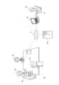
- FIG. 1 is a diagram illustrating an example of a usage mode of a system according to an embodiment.
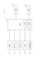
- FIG. 2 is a functional block diagram illustrating a schematic configuration of a first electronic device according to an embodiment.
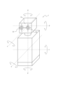
- 5A to 5C are diagrams illustrating an example of driving by a driving unit of the first electronic device according to an embodiment.
- FIG. 4 is a functional block diagram illustrating a schematic configuration of a second electronic device according to an embodiment.
- FIG. 4 is a functional block diagram illustrating a configuration of a third electronic device according to an embodiment.
- FIG. 2 is a sequence diagram illustrating a basic operation of a system according to an embodiment.
- 1 is a flowchart illustrating an operation of a system according to an embodiment.
- 1 is a flowchart illustrating an operation of a system according to an embodiment.
- an "electronic device” may be, for example, a device that is powered by power supplied from a power system or a battery.
- a “system” may be, for example, a device that includes at least an electronic device.
- a "user” may be a person who uses or may use an electronic device according to an embodiment (typically a human), and a person who uses or may use a system including an electronic device according to an embodiment.
- a conference in which at least one participant participates by communication from a different location than the other participants is collectively referred to as a "remote conference.”
- FIG. 1 is a diagram showing an example of how a system according to an embodiment is used.
- participant Mg remotely participates in a conference held in a conference room MR from his/her home RL, as shown in FIG. 1.
- participants Ma, Mb, Mc, and Md participate in the conference in the conference room MR.
- the participants of the conference are not limited to participants Ma, Mb, Mc, and Md, and may include, for example, other participants.
- the participants of the conference may be any number of at least one person. Participants other than participant Mg may also remotely participate in the conference from their respective homes.
- the system according to an embodiment may include, for example, a first electronic device 1, a second electronic device 100, and a third electronic device 300.
- the first electronic device 1, the second electronic device 100, and the third electronic device 300 are shown only in schematic form.
- the system according to an embodiment may not include at least any of the first electronic device 1, the second electronic device 100, and the third electronic device 300, and may include devices other than the electronic devices mentioned above.
- the first electronic device 1 may be installed in the conference room MR.
- the second electronic device 100 may be installed in the home RL of the participant Mg.
- the first electronic device 1 and the second electronic device 100 may be configured to be able to communicate with each other.
- the location of the home RL of the participant Mg may be a location different from the location of the conference room MR.
- the location of the home RL of the participant Mg may be far away from the location of the conference room MR, or may be close to the location of the conference room MR (for example, a room adjacent to the conference room MR).
- the first electronic device 1 according to an embodiment may be connected to the second electronic device 100 according to an embodiment, for example, via a network N.
- the third electronic device 300 according to an embodiment may be connected to at least one of the first electronic device 1 and the second electronic device 100, for example, via a network N.
- the first electronic device 1 according to an embodiment may be connected to the second electronic device 100 according to an embodiment, by at least one of wireless and wired.
- the third electronic device 300 according to an embodiment may be connected to at least one of the first electronic device 1 and the second electronic device 100, by at least one of wireless and wired.
- the first electronic device 1, the second electronic device 100, and the third electronic device 300 are shown by dashed lines as being connected wirelessly and/or wired via the network N.
- the first electronic device 1 and the second electronic device 100 may be included in a remote conference system according to an embodiment.
- the third electronic device 300 may be included in a remote conference system according to an embodiment.
- the network N as shown in FIG. 1 may include various electronic devices and/or devices such as a server as appropriate.
- the network N as shown in FIG. 1 may also include devices such as a base station and/or a repeater as appropriate.
- the first electronic device 1 and the second electronic device 100 may communicate directly.
- the first electronic device 1 and the second electronic device 100 may communicate via at least one of other devices such as the third electronic device 300, a repeater, and/or a base station.
- the communication unit of the first electronic device 1 and the communication unit of the second electronic device 100 may communicate.
- the above-mentioned notation may include the same intention as above not only when the first electronic device 1 and the second electronic device 100 "communicate” with each other, but also when one "sends” information to the other and/or when the other "receives” information sent by one. Furthermore, the above-mentioned notation may include the same intention as above not only when the first electronic device 1 and the second electronic device 100 "communicate” with each other, but also when any electronic device, including the third electronic device 300, communicates with any other electronic device.
- the first electronic device 1 may be arranged in the conference room MR, for example as shown in FIG. 1.
- the first electronic device 1 may be arranged in a position where it can acquire the voice and/or video of at least one of the conference participants Ma, Mb, Mc, and Md.
- the first electronic device 1 outputs the voice and/or video of participant Mg, as described below. Therefore, the first electronic device 1 may be arranged so that the voice and/or video of participant Mg output from the first electronic device 1 reaches at least one of the conference participants Ma, Mb, Mc, and Md.
- the second electronic device 100 may be arranged in the home RL of the participant Mg, for example, in a manner as shown in FIG. 1.
- the second electronic device 100 may be arranged in a position where it is possible to acquire the voice and/or image of the participant Mg.
- the second electronic device 100 may acquire the voice and/or image of the participant Mg by a microphone or a headset and/or a camera connected to the second electronic device 100.
- the second electronic device 100 may acquire information on the gaze of the participant Mg, such as the gaze of the participant Mg, the direction of the gaze, and/or the movement of the gaze, as described below. The acquisition of gaze information by the second electronic device 100 will be described further below.
- the second electronic device 100 outputs the audio and/or video of at least one of the participants Ma, Mb, Mc, and Md of the conference in the conference room MR, as described below. For this reason, the second electronic device 100 may be positioned so that the audio and/or video output from the second electronic device 100 reaches the participant Mg.
- the audio output from the second electronic device 100 may be positioned so that it reaches the ears of the participant Mg, for example, via headphones, earphones, speakers, or a headset.
- the video output from the second electronic device 100 may be positioned so that it is visually recognized by the participant Mg, for example, via a display.
- the third electronic device 300 may be, for example, a server-like device that relays between the first electronic device 1 and the second electronic device 100. Also, the system according to one embodiment does not need to include the third electronic device 300.
- FIG. 1 shows only one example of a usage mode of the first electronic device 1, the second electronic device 100, and the third embodiment 300 according to an embodiment.
- the first electronic device 1, the second electronic device 100, and the third embodiment 300 according to an embodiment may be used in various other modes.
- the remote conference system including the first electronic device 1 and the second electronic device 100 shown in FIG. 1 allows the participant Mg to behave as if he or she is participating in a conference held in the conference room MR while staying at home RL. Also, the remote conference system including the first electronic device 1 and the second electronic device 100 shown in FIG. 1 allows the conference participants Ma, Mb, Mc, and Md to feel as if the participant Mg is actually participating in the conference held in the conference room MR. That is, in the remote conference system including the first electronic device 1 and the second electronic device 100, the first electronic device 1 arranged in the conference room MR can play a role like an avatar of the participant Mg.
- the first electronic device 1 may function as a physical avatar (such as a telepresence robot) that resembles the participant Mg. Also, the first electronic device 1 may function as a virtual avatar that displays an image of the participant Mg or an image of the participant Mg that is, for example, a character.
- the image of participant Mg or the display of the image of participant Mg by the first electronic device 1 may be, for example, a display provided in the first electronic device 1 itself, an external display, or a 3D hologram projected by the first electronic device 1.
- the first electronic device 1 may be used in the conference room MR by participants Ma, Mb, Mc, Md, etc.
- the second electronic device 100 described later has a function of outputting the voice, video, and/or gaze information of the participant Mg acquired by the second electronic device 100 when the participant Mg speaks to the first electronic device 1.
- the first electronic device 1 also has a function of outputting the voice and/or video of the participants Ma, Mb, Mc, Md, etc. acquired by the first electronic device 1 when the participants Ma, Mb, Mc, Md, etc. speak to the second electronic device 100.
- the first electronic device 1 allows the participants Ma, Mb, Mc, Md, etc. to hold a remote conference or video conference in the conference room MR even if the participant Mg is in a remote location. Therefore, the first electronic device 1 is also referred to as an electronic device "used locally" as appropriate.
- the first electronic device 1 may be configured to reproduce the line of sight of the participant Mg. That is, the first electronic device 1 can perform an operation that simulates the line of sight of the participant Mg. Specifically, the first electronic device 1 can cause the participants Ma, Mb, Mc, Md, etc. in the conference room MR to recognize in which direction the participant Mg is looking. For example, the first electronic device 1 can cause people around the first electronic device 1 in the conference room MR to recognize whether the participant Mg is looking at the participant Ma, whether the participant Mg is looking at the participant Mb, or whether the participant Mg is not looking at any of the participants.
- the first electronic device 1 may be various devices, but may be, for example, a specially designed device.
- the first electronic device 1 according to one embodiment may have a housing with an illustration of a human or the like drawn on it, or may have a shape that imitates at least a part of a human or the like or a robot-like shape.
- the first electronic device 1 according to one embodiment may be, for example, a general-purpose smartphone, tablet, phablet, notebook computer (notebook PC or laptop), or computer (desktop).
- the first electronic device 1 may draw at least a part of a human or robot on the display of a notebook PC, for example.
- the first electronic device 1 according to one embodiment may project at least a part of a human or robot as a 3D hologram, for example.
- the first electronic device 1 may include a control unit 10, a memory unit 20, a communication unit 30, an imaging unit 40, an audio input unit 50, an audio output unit 60, a display unit 70, and a drive unit 80.
- the control unit 10 may also include, for example, an identification unit 12 and an estimation unit 14.
- the first electronic device 1 may not include at least some of the functional units shown in FIG. 2, or may include components other than the functional units shown in FIG. 2.
- the control unit 10 controls and/or manages the entire first electronic device 1, including each functional unit constituting the first electronic device 1.
- the control unit 10 may include at least one processor, such as a CPU (Central Processing Unit) or a DSP (Digital Signal Processor), to provide control and processing power for executing various functions.
- the control unit 10 may be realized as a single processor, as a number of processors, or as individual processors.
- the processor may be realized as a single integrated circuit (IC).
- the processor may be realized as a number of communicatively connected integrated circuits and discrete circuits.
- the processor may be realized based on various other known technologies.
- the control unit 10 may include one or more processors and memories.
- the processor may include a general-purpose processor that loads a specific program to execute a specific function, and a dedicated processor specialized for a specific process.
- the dedicated processor may include an application specific integrated circuit (ASIC).
- the processor may include a programmable logic device (PLD).
- the PLD may include a field-programmable gate array (FPGA).
- the control unit 10 may be either a system-on-a-chip (SoC) or a system in a package (SiP) in which one or more processors work together.
- SoC system-on-a-chip
- SiP system in a package
- the control unit 10 may be configured to include, for example, at least one of software and hardware resources. Furthermore, in the first electronic device 1 according to one embodiment, the control unit 10 may be configured by specific means in which software and hardware resources work together. Furthermore, in the first electronic device 1 according to one embodiment, at least one of the other functional units may also be configured by specific means in which software and hardware resources work together.
- control unit 10 performs various operations such as control, which will be described later.
- the determination unit 12 of the control unit 10 can perform various determination processes.
- the estimation unit 14 can perform various estimation processes.
- the storage unit 20 may function as a memory that stores various information.
- the storage unit 20 may store, for example, a program executed in the control unit 10 and the results of processing executed in the control unit 10.
- the storage unit 20 may also function as a work memory for the control unit 10.
- the storage unit 20 may be connected to the control unit 10 by wire and/or wirelessly.
- the storage unit 20 may include, for example, at least one of a RAM (Random Access Memory) and a ROM (Read Only Memory).
- the storage unit 20 may be configured, for example, by a semiconductor memory or the like, but is not limited to this, and may be any storage device.
- the storage unit 20 may be a storage medium such as a memory card inserted into the first electronic device 1 according to one embodiment.
- the storage unit 20 may also be an internal memory of a CPU used as the control unit 10, or may be connected to the control unit 10 as a separate unit.
- the communication unit 30 has an interface function for wireless and/or wired communication with, for example, an external device.
- the communication method performed by the communication unit 30 in one embodiment may be a wireless communication standard.
- the wireless communication standard includes cellular phone communication standards such as 2G, 3G, 4G, and 5G.
- the cellular phone communication standards include LTE (Long Term Evolution), W-CDMA (Wideband Code Division Multiple Access), CDMA2000, PDC (Personal Digital Cellular), GSM (Registered Trademark) (Global System for Mobile communications), and PHS (Personal Handy-phone System), etc.
- wireless communication standards include WiMAX (Worldwide Interoperability for Microwave Access), IEEE 802.11, WiFi, Bluetooth (registered trademark), IrDA (Infrared Data Association), and NFC (Near Field Communication).
- the communication unit 30 may include, for example, a modem whose communication method is standardized by ITU-T (International Telecommunication Union Telecommunication Standardization Sector).
- ITU-T International Telecommunication Union Telecommunication Standardization Sector
- the communication unit 30 may be configured to include, for example, an antenna for transmitting and receiving radio waves and an appropriate RF unit.
- the communication unit 30 may wirelessly communicate with, for example, a communication unit of another electronic device via an antenna.
- the communication unit 30 may have a function of transmitting any information from the first electronic device 1 to another device, and/or a function of receiving any information from another device in the first electronic device 1.
- the communication unit 30 may wirelessly communicate with the second electronic device 100 shown in FIG. 1.
- the communication unit 30 may wirelessly communicate with a communication unit 130 (described later) of the second electronic device 100.
- the communication unit 30 has a function of communicating with the second electronic device 100.
- the communication unit 30 may wirelessly communicate with the third electronic device 300 shown in FIG. 1.
- the communication unit 30 may wirelessly communicate with a communication unit 330 (described later) of the third electronic device 300.
- the communication unit 30 may have a function of communicating with the third electronic device 300.
- the communication unit 30 may also be configured as an interface such as a connector for wired connection to the outside.
- the communication unit 30 can be configured using known technology for wireless communication, so a detailed description of the hardware and the like is omitted.
- the communication unit 30 may be connected to the control unit 10 via a wired and/or wireless connection.
- Various pieces of information received by the communication unit 30 may be supplied to, for example, the storage unit 20 and/or the control unit 10.
- Various pieces of information received by the communication unit 30 may be stored in, for example, a memory built into the control unit 10.
- the communication unit 30 may transmit, for example, the results of processing by the control unit 10 and/or information stored in the storage unit 20 to the outside.
- the imaging unit 40 may be configured to include an image sensor that captures images electronically, such as a digital camera.
- the imaging unit 40 may be configured to include an imaging element that performs photoelectric conversion, such as a CCD (Charge Coupled Device Image Sensor) or a CMOS (Complementary Metal Oxide Semiconductor) sensor.
- the imaging unit 40 can capture an image of the surroundings of the first electronic device 1, for example.
- the imaging unit 40 may capture an image of the inside of the conference room MR shown in FIG. 1, for example.
- the imaging unit 40 may capture images of participants Ma, Mb, Mc, and Md of a conference held in the conference room MR shown in FIG. 1, for example.
- the imaging unit 40 may be configured to capture video having a predetermined range of angle of view centered on a specific direction. For example, the imaging unit 40 according to one embodiment may capture video centered on participant Mb in FIG. 1, where participant Ma and/or participant Md are not included in the angle of view.
- the imaging unit 40 may also be configured to simultaneously capture video in all directions (e.g., 360 degrees), such as the horizontal direction.
- the imaging unit 40 may capture all-directional video including participants Ma, Mb, Mc, and Md in FIG. 1.
- the imaging unit 40 may convert the captured image into a signal and transmit it to the control unit 10. For this reason, the imaging unit 40 may be connected to the control unit 10 via a wired and/or wireless connection. Furthermore, a signal based on the image captured by the imaging unit 40 may be supplied to any functional unit of the first electronic device 1, such as the memory unit 20 and/or the display unit 70.
- the imaging unit 40 is not limited to an imaging device such as a digital camera, and may be any device that captures an image of the state inside the conference room MR shown in FIG. 1.
- the imaging unit 40 may capture images of the state inside the conference room MR as still images at predetermined time intervals (e.g., 15 frames per second). Also, in one embodiment, the imaging unit 40 may capture images of the state inside the conference room MR as a continuous video. Furthermore, the imaging unit 40 may be configured to include a fixed camera, or may be configured to include a movable camera.
- the voice input unit 50 detects (acquires) sounds or voices around the first electronic device 1, including human voices.
- the voice input unit 50 may detect sounds or voices as air vibrations, for example, with a diaphragm, and convert them into an electrical signal.
- the voice input unit 50 may include an acoustic device that converts sounds into an electrical signal, such as a microphone.
- the voice input unit 50 may detect (acquire) the voices of at least one of the participants Ma, Mb, Mc, and Md in the conference room MR shown in FIG. 1, for example.
- the voices (electrical signals) detected by the voice input unit 50 may be input to the control unit 10, for example. For this reason, the voice input unit 50 may be connected to the control unit 10 by wire and/or wirelessly.
- the audio input unit 50 may be configured to include, for example, a stereo microphone or a microphone array.
- An audio input unit 50 including multiple channels, such as a stereo microphone or a microphone array can identify (or estimate) the direction and/or position of a sound source. With such an audio input unit 50, it can be identified (or estimated) from which direction and/or position a sound detected in, for example, a conference room MR originates, based on the first electronic device 1 equipped with the audio input unit 50.
- the audio input unit 50 may convert the acquired sound or voice into an electrical signal and supply it to the control unit 10.
- the audio input unit 50 may also supply the electrical signal (audio signal) into which the sound or voice has been converted to a functional unit of the first electronic device 1, such as the memory unit 20.
- the audio input unit 50 may be any device that detects (acquires) sound or voice within the conference room MR shown in FIG. 1.
- the audio output unit 60 converts an electrical signal (audio signal) of sound or voice supplied from the control unit 10 into sound, and outputs the audio signal as sound or voice.
- the audio output unit 60 may be connected to the control unit 10 by wire and/or wirelessly.
- the audio output unit 60 may be configured to include a device having a function of outputting sound, such as an arbitrary speaker (loudspeaker).
- the audio output unit 60 may be configured to include a directional speaker that transmits sound in a specific direction.
- the audio output unit 60 may also be configured to be able to change the directionality of the sound.
- the audio output unit 60 may include an amplifier or an amplification circuit that appropriately amplifies the electrical signal (audio signal).
- the audio output unit 60 may amplify the audio signal that the communication unit 30 receives from the second electronic device 100.
- the audio signal received from the second electronic device 100 may be, for example, the audio signal of a speaker (e.g., participant Mg shown in FIG. 1) who is speaking (currently speaking) that is received by the communication unit 30 from the second electronic device 100 of that speaker.
- the audio output unit 60 may output the audio signal of a speaker (e.g., participant Mg shown in FIG. 1) as the voice of that speaker.
- the display unit 70 may be any display device, such as a Liquid Crystal Display (LCD), an Organic Electro-Luminescence panel, or an Inorganic Electro-Luminescence panel.
- the display unit 70 may also be, for example, a projector that projects a 3D hologram.
- the display unit 70 may display various types of information, such as characters, figures, or symbols.
- the display unit 70 may also display objects and icon images that constitute various GUIs, for example, to prompt the user to operate the first electronic device 1.
- the display unit 70 may be connected to the control unit 10 or the like by wire and/or wirelessly.
- the display unit 70 may be configured to include a backlight, etc., as appropriate.
- the display unit 70 may display an image based on a video signal transmitted from the second electronic device 100.
- the second electronic device 100 acquires, for example, audio, video, and/or gaze information of the participant Mg shown in FIG. 1 and outputs it to the first electronic device 1.
- the display unit 70 may then represent the gaze of the participant Mg in the image based on the video and/or gaze information of the participant Mg input from the first electronic device 1.
- the participants Ma, Mb, Mc, and Md shown in FIG. 1 can visually know the gaze of the participant Mg who is in a location away from the conference room MR.
- the display unit 70 may display, for example, an image of the gaze of the participant Mg captured by the second electronic device 100 as is.
- the display unit 70 may display, for example, an image that characterizes the gaze of the participant Mg (for example, the gaze of an avatar or robot).
- the display unit 70 may represent the gaze of the user of the second electronic device 100 by an image.
- the display unit 70 may also represent the gaze direction and/or gaze movement of the user of the second electronic device 100 by an image.
- the first electronic device 1 may include a display unit 70 that represents the gaze and/or gaze direction of the user of the second electronic device 100 by an image.
- the driving unit 80 drives a specific moving part in the first electronic device 1.
- the driving unit 80 may be configured to include a power source such as a servo motor that drives the moving part in the first electronic device 1.
- the driving unit 80 may drive any moving part in the first electronic device 1 under the control of the control unit 10. For this reason, the driving unit 80 may be connected to the control unit 10 by wire and/or wirelessly.
- the driving unit 80 may drive, for example, at least a part of the housing of the first electronic device 1. Furthermore, for example, when the first electronic device 1 has a shape that imitates at least a part of a human or a robot, the driving unit 80 may drive at least a part of the shape of a human or a robot. In particular, when the first electronic device 1 has a shape that imitates at least a part of a human face or a robot face, the driving unit 80 may represent the line of sight, line of sight direction, and/or line of sight movement of a human or a robot by a physical configuration (shape) and/or movement.
- the second electronic device 100 acquires, for example, audio, video, and/or gaze information of the participant Mg shown in FIG. 1 and outputs it to the first electronic device 1.
- the drive unit 80 may represent the gaze of the image of the participant Mg by a physical configuration (shape) and/or movement based on the video and/or gaze information of the participant Mg input from the first electronic device 1.
- the drive unit 80 of the first electronic device 1 representing the gaze of the participant Mg, for example, the participants Ma, Mb, Mc, and Md shown in FIG. 1 can visually know the gaze state of the participant Mg who is in a location away from the conference room MR.
- the driving unit 80 may directly reproduce the gaze direction and/or movement of the participant Mg captured by the second electronic device 100, for example.
- the driving unit 80 may express the gaze direction and/or movement of the participant Mg in a characterized form (such as the gaze of an avatar or robot).
- the driving unit 80 may express the gaze, gaze direction, and/or gaze movement of the user of the second electronic device 100 by a physical configuration (form) and/or movement.
- the first electronic device 1 may include a driving unit 80 that expresses the gaze and/or gaze direction of the user of the second electronic device 100 by driving a mechanical structure.
- FIG. 3 is a diagram illustrating an example of the operation of the driving unit 80 in the first electronic device 1 according to one embodiment.
- the driving unit 80 may realize driving about at least one of the driving axes ⁇ , ⁇ , ⁇ , ⁇ , ⁇ , and ⁇ in the first electronic device 1.
- the driving unit 80 may express a negative movement (shaking the head from side to side) of the user of the second electronic device 100 (e.g., participant Mg) by performing driving about the driving axis ⁇ in the first electronic device 1.
- the driving unit 80 may express a positive movement (nodding movement) of the user of the second electronic device 100 (e.g., participant Mg) by performing driving about the driving axis ⁇ in the first electronic device 1.
- the driving unit 80 may express a movement (tilting the head) in which the user of the second electronic device 100 (e.g., participant Mg) is undecided by performing driving about the driving axis ⁇ in the first electronic device 1. Also, for example, the driving unit 80 may express a negative or rejecting movement (shaking the body from side to side) of the user of the second electronic device 100 (e.g., participant Mg) by performing driving about the driving axis ⁇ of the first electronic device 1. Also, for example, the driving unit 80 may express a polite movement (bowing) of the user of the second electronic device 100 (e.g., participant Mg) by performing driving about the driving axis ⁇ of the first electronic device 1. Also, for example, the driving unit 80 may express a movement of the user of the second electronic device 100 (e.g., participant Mg) by performing driving about the driving axis ⁇ of the first electronic device 1.
- the driving unit 80 may express the movement of the eyes E1 and E2 in the face portion Fc of the first electronic device 1 shown in FIG. 3, that is, the line of sight of the user (e.g., participant Mg) of the second electronic device 100.
- the driving unit 80 may express the line of sight of the user (e.g., participant Mg) of the second electronic device 100 by driving at least one of the eyes E1 and E2 in the face portion Fc of the first electronic device 1.
- the driving unit 80 may express the line of sight of the user (e.g., participant Mg) of the second electronic device 100 by driving the movement of at least one of the eyes E1 and E2 in the face portion Fc of the first electronic device 1.
- the driving unit 80 may express the line of sight of the user (e.g., participant Mg) of the second electronic device 100 by moving, for example, at least one of the eyes E1 and E2 in the face portion Fc of the first electronic device 1 in any direction of the arrows shown in FIG. 3.
- the display unit 70 may represent the gaze of the user of the second electronic device 100 (e.g., participant Mg) by displaying, for example, the eyes E1 and E2 in the face portion Fc shown in FIG. 3.
- at least one of the display unit 70 and the drive unit 80 may represent the gaze of the user of the second electronic device 100 (e.g., participant Mg) by displaying at least one of the eyes E1 and E2 of the first electronic device 1.
- various operations expressing the emotions and/or behavior of a human being such as participant Mg can be expressed by displaying the display unit 70 and/or driving the drive unit 80.
- Various known techniques may be used for the operations expressing the emotions and/or behavior of a human being such as participant Mg by displaying the display unit 70 and/or driving the drive unit 80. For this reason, a detailed description of the operations expressing the emotions and/or behavior of a human being such as participant Mg by displaying the display unit 70 and/or driving the drive unit 80 will be omitted.
- the first electronic device 1 according to one embodiment can perform operations expressing the emotions and/or behavior of participant Mg by displaying the display unit 70 and/or driving the drive unit 80.
- the first electronic device 1 may be a dedicated device as described above. Meanwhile, in one embodiment, the first electronic device 1 may include, for example, an audio output unit 60 and a drive unit 80 among the functional units shown in FIG. 2. In this case, the first electronic device 1 may be connected to another electronic device to supplement at least some of the functions of the other functional units shown in FIG. 2.
- the other electronic device may be, for example, a general-purpose smartphone, tablet, phablet, notebook computer (notebook PC or laptop), or computer (desktop).
- the manner in which various actions expressing the emotions and/or behavior of a human being such as participant Mg are expressed by the display unit 70 and/or the drive unit 80 in the first electronic device 1 shown in FIG. 3 may merely be considered as examples that can be envisioned.
- the first electronic device 1 may express various actions expressing the emotions and/or behavior of a human being such as participant Mg by using various configurations and/or operating modes.
- FIG. 4 is a block diagram showing a schematic configuration of the second electronic device 100 shown in FIG. 1.
- the second electronic device 100 may be, for example, an device used by the participant Mg at his/her home RL.
- the above-mentioned first electronic device 1 has a function of outputting the voice and/or video of the participants Ma, Mb, Mc, Md, etc. acquired by the first electronic device 1 when the participants Ma, Mb, Mc, Md, etc. speak to the second electronic device 100.
- the first electronic device 1 can express the gaze of the participant Mg.
- the second electronic device 100 has a function of outputting the voice and/or video of the participant Mg acquired by the second electronic device 100 to the first electronic device 1 when the participant Mg speaks. Furthermore, the second electronic device 100 has a function of outputting the gaze information of the participant Mg acquired by the second electronic device 100 to the first electronic device 1.
- the second electronic device 100 allows the participants Mg to hold a remote conference or video conference even when they are in a location far from the conference room MR. Therefore, the second electronic device 100 is also referred to as an electronic device "used remotely" as appropriate.
- the second electronic device 100 may include a control unit 110, a memory unit 120, a communication unit 130, an imaging unit 140, an audio input unit 150, an audio output unit 160, a display unit 170, and a gaze information acquisition unit 200.
- the control unit 110 may also include, for example, an identification unit 112 and an estimation unit 114.
- the second electronic device 100 may not include at least some of the functional units shown in FIG. 4, or may include components other than the functional units shown in FIG. 4.
- the control unit 110 controls and/or manages the entire second electronic device 100, including each functional unit constituting the second electronic device 100.
- the control unit 110 may basically be configured based on the same concept as the control unit 10 shown in FIG. 2, for example.
- the identification unit 112 and estimation unit 114 of the control unit 110 may also be configured based on the same concept as the identification unit 12 and estimation unit 14 of the control unit 10 shown in FIG. 2, for example.
- the storage unit 120 may function as a memory that stores various types of information.
- the storage unit 120 may store, for example, programs executed in the control unit 110 and results of processing executed in the control unit 110.
- the storage unit 120 may also function as a work memory for the control unit 110.
- the storage unit 120 may be connected to the control unit 110 via a wired and/or wireless connection.
- the storage unit 120 may basically be configured based on the same concept as the storage unit 20 shown in FIG. 2, for example.
- the communication unit 130 has an interface function for wireless and/or wired communication.
- the communication unit 130 may wirelessly communicate with, for example, a communication unit of another electronic device, for example, via an antenna.
- the communication unit 130 may wirelessly communicate with the first electronic device 1 shown in FIG. 1.
- the communication unit 130 may wirelessly communicate with the communication unit 30 of the first electronic device 1.
- the communication unit 130 has a function of communicating with the first electronic device 1.
- the communication unit 130 may wirelessly communicate with the third electronic device 300 shown in FIG. 1.
- the communication unit 130 may wirelessly communicate with the communication unit 330 (described later) of the third electronic device 300.
- the communication unit 130 may have a function of communicating with the third electronic device 300.
- the communication unit 130 may be connected to the control unit 110 in a wired and/or wireless manner.
- the communication unit 130 may basically have a configuration based on the same idea as the communication unit 30 shown in FIG. 2, for example.
- the imaging unit 140 may be configured to include an image sensor that captures images electronically, such as a digital camera.
- the imaging unit 140 may capture images of the interior of the home RL shown in FIG. 1, for example.
- the imaging unit 140 may capture images of participants Mg who join a conference from the home RL shown in FIG. 1, for example.
- the imaging unit 140 may convert the captured images into signals and transmit them to the control unit 110. For this reason, the imaging unit 140 may be connected to the control unit 110 by wire and/or wirelessly.
- the imaging unit 140 may basically be configured based on the same concept as the imaging unit 40 shown in FIG. 2, for example.
- the audio input unit 150 detects (acquires) sounds or voices around the second electronic device 100, including human voices.
- the audio input unit 150 may detect sounds or voices as air vibrations, for example, with a diaphragm, and convert them into an electrical signal.
- the audio input unit 150 may include an acoustic device that converts sounds into an electrical signal, such as an arbitrary microphone.
- the audio input unit 150 may detect (acquire) the voice of the participant Mg in the home RL shown in FIG. 1, for example.
- the voice (electrical signal) detected by the audio input unit 150 may be input to the control unit 110, for example. For this reason, the audio input unit 150 may be connected to the control unit 110 by wire and/or wirelessly.
- the audio input unit 150 may basically be configured based on the same concept as the audio input unit 50 shown in FIG. 2, for example.
- the audio output unit 160 converts an electrical signal (audio signal) supplied from the control unit 110 into sound, and outputs the audio signal as sound or voice.
- the audio output unit 160 may be connected to the control unit 110 by wire and/or wirelessly.
- the audio output unit 160 may be configured to include a device having a function of outputting sound, such as an arbitrary speaker (loudspeaker).
- the audio output unit 160 may output a sound detected by the audio input unit 50 of the first electronic device 1.
- the sound detected by the audio input unit 50 of the first electronic device 1 may be at least one of the voices of the participants Ma, Mb, Mc, and Md in the conference room MR shown in FIG. 1.
- the audio output unit 160 may basically be configured based on the same idea as the audio output unit 60 shown in FIG. 2, for example.
- the display unit 170 may be any display device, such as a Liquid Crystal Display (LCD), an Organic Electro-Luminescence panel, or an Inorganic Electro-Luminescence panel.
- the display unit 170 may basically be configured based on the same concept as the display unit 70 shown in FIG. 2, for example.
- Various data required for display on the display unit 170 may be supplied from, for example, the control unit 110 or the memory unit 120. For this reason, the display unit 170 may be connected to the control unit 110, etc., via a wired and/or wireless connection.
- the display unit 170 may be, for example, a touch screen display equipped with a touch panel function that detects input by contact with the participant Mg's finger or stylus.
- the display unit 170 may display an image based on the video signal transmitted from the first electronic device 1.
- the display unit 170 may display images of participants Ma, Mb, Mc, Md, etc. captured by the first electronic device 1 (its imaging unit 40) as an image based on the video signal transmitted from the first electronic device 1.
- participant Mg shown in FIG. 1 can visually know the state of participants Ma, Mb, Mc, Md, etc. in a conference room MR away from his/her home RL.
- the display unit 170 may directly display images of the participants Ma, Mb, Mc, Md, etc. captured by the first electronic device 1. On the other hand, the display unit 170 may display images (e.g., avatars) that characterize the participants Ma, Mb, Mc, Md, etc.
- images e.g., avatars
- the gaze information acquisition unit 200 acquires gaze information of the user of the second electronic device 100 (e.g., participant Mg).
- the gaze information acquisition unit 200 may acquire gaze information of the user of the second electronic device 100, such as the gaze of the user of the second electronic device 100, the direction of the gaze, and/or the movement of the gaze.
- the gaze information acquisition unit 200 may have a function of tracking the movement of the gaze of the user of the second electronic device 100 (e.g., participant Mg), such as an eye tracker.
- the gaze information acquisition unit 200 may be any component capable of acquiring gaze information of the user of the second electronic device 100, such as the gaze of the user of the second electronic device 100, the direction of the gaze, and/or the movement of the gaze.
- the second electronic device 100 may acquire gaze information of a user (e.g., participant Mg) of the second electronic device 100 based on the eye movement of the user captured by the imaging unit 140.
- the second electronic device 100 may not include the gaze information acquisition unit 200, or the imaging unit 140 may also function as the gaze information acquisition unit 200.
- the gaze information acquired by the gaze information acquisition unit 200 may be input to the control unit 110, for example. For this reason, the gaze information acquisition unit 200 may be connected to the control unit 110 via a wired and/or wireless connection.
- the second electronic device 100 may be a dedicated device as described above. Meanwhile, in one embodiment, the second electronic device 100 may include some of the functional units shown in FIG. 4, for example. In this case, the second electronic device 100 may be connected to another electronic device to supplement at least some of the functions of the other functional units shown in FIG. 4.
- the other electronic device may be, for example, a general-purpose smartphone, tablet, phablet, notebook computer (notebook PC or laptop), or computer (desktop), etc.
- the second electronic device 100 may be a smartphone or a laptop computer.
- the second electronic device 100 may be a smartphone or a laptop computer with an application (program) installed for linking with the first electronic device 1.
- FIG. 5 is a block diagram showing a schematic configuration of the third electronic device 300 shown in FIG. 1. An example of the configuration of the third electronic device 300 according to an embodiment will be described below.
- the third electronic device 300 may be installed in a location other than the participant Mg's home RL and the conference room MR, as shown in FIG. 1.
- the third electronic device 300 may be installed in the participant Mg's home RL or nearby, or in the conference room MR or nearby.
- the first electronic device 1 has a function of transmitting the audio and/or video data of the participants Ma, Mb, Mc, Md, etc. acquired by the first electronic device 1 to the third electronic device 300 when the participants Ma, Mb, Mc, Md, etc. speak.
- the third electronic device 300 may transmit the audio and/or video data received from the first electronic device 1 to the second electronic device 100.
- the second electronic device 100 also has a function of transmitting the audio and/or video data of the participant Mg acquired by the second electronic device 100 to the third electronic device 300 when the participant Mg speaks.
- the third electronic device 300 may transmit the audio and/or video data received from the second electronic device 100 to the first electronic device 1. In this way, the third electronic device 300 may have a function of relaying between the first electronic device 1 and the second electronic device 100.
- the third electronic device 100 is also referred to as a "server" as appropriate.
- the third electronic device 300 may include a control unit 310, a storage unit 320, and a communication unit 330.
- the control unit 310 may also include, for example, an identification unit 312 and an estimation unit 314.
- the third electronic device 300 may not include at least some of the functional units shown in FIG. 5, or may include components other than the functional units shown in the figure.
- the control unit 310 controls and/or manages the entire third electronic device 300, including each functional unit constituting the third electronic device 300.
- the control unit 310 may basically be configured based on the same concept as the control unit 10 shown in FIG. 2, for example.
- the identification unit 312 and estimation unit 314 of the control unit 310 may also be configured based on the same concept as the identification unit 12 and estimation unit 14 of the control unit 10 shown in FIG. 2, for example.
- the storage unit 320 may function as a memory that stores various types of information.
- the storage unit 320 may store, for example, programs executed in the control unit 310 and results of processing executed in the control unit 310.
- the storage unit 320 may also function as a work memory for the control unit 310.
- the storage unit 320 may be connected to the control unit 310 via a wired and/or wireless connection.
- the storage unit 320 may basically be configured based on the same concept as the storage unit 20 shown in FIG. 2, for example.
- the communication unit 330 has an interface function for wireless and/or wired communication.
- the communication unit 330 may wirelessly communicate with, for example, a communication unit of another electronic device, for example, via an antenna.
- the communication unit 330 may wirelessly communicate with the first electronic device 1 shown in FIG. 1.
- the communication unit 330 may wirelessly communicate with the communication unit 30 of the first electronic device 1.
- the communication unit 330 has a function of communicating with the first electronic device 1.
- the communication unit 330 may wirelessly communicate with the second electronic device 100 shown in FIG. 1.
- the communication unit 330 may wirelessly communicate with the communication unit 130 of the second electronic device 100.
- the communication unit 330 may have a function of communicating with the second electronic device 100. As shown in FIG. 5, the communication unit 330 may be connected to the control unit 310 in a wired and/or wireless manner. The communication unit 330 may basically be configured based on the same idea as the communication unit 30 shown in FIG. 2.
- the third electronic device 300 may be, for example, a specially designed device.
- the third electronic device 300 may include, for example, some of the functional units shown in FIG. 5.
- the third electronic device 300 may be connected to other electronic devices to supplement at least some of the functions of the other functional units shown in FIG. 5.
- the other electronic devices may be, for example, devices such as a general-purpose computer or server.
- the third electronic device 300 may be, for example, a relay server, a web server, or an application server.
- the first electronic device 1 is installed in the conference room MR and acquires video and/or audio of at least one of the participants Ma, Mb, Mc, and Md.
- the video and/or audio acquired by the first electronic device 1 is transmitted to the second electronic device 100 installed in the home RL of the participant Mg.
- the second electronic device 100 outputs the video and/or audio of at least one of the participants Ma, Mb, Mc, and Md acquired by the first electronic device 1. This allows the participant Mg to recognize the video and/or audio of at least one of the participants Ma, Mb, Mc, and Md.
- the second electronic device 100 is installed in the home RL of the participant Mg and acquires the voice of the participant Mg.
- the second electronic device 100 also acquires information on the gaze of the participant Mg.
- the voice and/or gaze information acquired by the second electronic device 100 is transmitted to the first electronic device 1 installed in the conference room MR.
- the first electronic device 1 outputs the voice of the participant Mg received from the second electronic device 100.
- at least one of the participants Ma, Mb, Mc, and Md can hear the voice of the participant Mg.
- the first electronic device 1 also expresses the gaze of the participant Mg based on the gaze information of the participant Mg received from the second electronic device 100.
- the second electronic device 100 may acquire an image of the participant Mg.
- the image acquired by the second electronic device 100 may be transmitted to the first electronic device 1 installed in the conference room MR.
- the first electronic device 1 may output the video of the participant Mg received from the second electronic device 100.
- FIG. 6 is a sequence diagram explaining the basic operation of the system according to the embodiment described above.
- FIG. 6 is a diagram showing the exchange of data and the like between the first electronic device 1, the second electronic device 100, and the third electronic device 300.
- the basic operation when a remote conference or video conference is held using the system according to the embodiment will be explained with reference to FIG. 6.
- the first electronic device 1 used locally may be used by the first user.
- the first user may be, for example, at least one of the participants Ma, Mb, Mc, and Md shown in FIG. 1 (hereinafter also referred to as a local user).
- the second electronic device 100 used remotely may be used by the second user.
- the second user may be, for example, the participant Mg shown in FIG. 1 (hereinafter also referred to as a remote user).
- the operation performed by the first electronic device 1 may be, in more detail, performed by, for example, the control unit 10 of the first electronic device 1.
- the operation performed by the control unit 10 of the first electronic device 1 may be referred to as the operation performed by the first electronic device 1.
- the operation performed by the second electronic device 100 may be, in more detail, performed by, for example, the control unit 110 of the second electronic device 100.
- the operation performed by the control unit 110 of the second electronic device 100 may be referred to as the operation performed by the second electronic device 100.
- the operations performed by the third electronic device 300 may be more specifically performed by, for example, the control unit 310 of the third electronic device 300.
- the operations performed by the control unit 310 of the third electronic device 300 may be referred to as operations performed by the third electronic device 300.
- the first electronic device 1 acquires at least one of the video and audio of the first user (e.g., at least one of the participants Ma, Mb, Mc, and Md) (step S1). Specifically, in step S1, the first electronic device 1 may capture the video of the first user using the imaging unit 40 and acquire (or detect) the audio of the first user using the audio input unit 50. Next, the first electronic device 1 encodes at least one of the video and audio of the first user (step S2). In step S2, encoding may mean compressing the video and/or audio data according to a predetermined rule and converting it into a format according to the purpose, including encryption. The first electronic device 1 may perform various known encoding methods, such as software encoding or hardware encoding.
- the first electronic device 1 transmits the encoded video and/or audio data to the third electronic device 300 (step S3). Specifically, in step S3, the first electronic device 1 transmits the video and/or audio data from the communication unit 30 to the communication unit 330 of the third electronic device 300. Also in step S3, the third electronic device 300 receives the video and/or audio data transmitted from the communication unit 30 of the first electronic device 1 via the communication unit 330.
- the third electronic device 300 transmits the encoded video and/or audio data received from the communication unit 30 to the second electronic device 100 (step S4). Specifically, in step S4, the third electronic device 300 transmits the video and/or audio data from the communication unit 330 to the communication unit 130 of the second electronic device 100. Also, in step S4, the second electronic device 100 receives the video and/or audio data transmitted from the communication unit 330 of the third electronic device 300 via the communication unit 130.
- step S5 decodes the encoded video and/or audio data received from the communication unit 330 (step S5).
- decoding may mean returning the format of the encoded video and/or audio data to its original format.
- the second electronic device 100 may perform various known decoding methods, such as software encoding or hardware encoding.
- the second electronic device 100 presents at least one of the video and audio of the first user (e.g., at least one of participants Ma, Mb, Mc, and Md) to the second user (e.g., participant Mg) (step S6).
- the second electronic device 100 may display the video of the first user on the display unit 170 and output the audio of the first user from the audio output unit 160.
- a second user e.g., participant Mg
- a first user e.g., at least one of participants Ma, Mb, Mc, and Md
- the above describes a manner in which the first electronic device 1 transmits video and/or audio of the first user to the second electronic device 100 via the third electronic device 300.
- the second electronic device 100 can transmit audio and/or gaze information of the second user to the first electronic device 1 via the third electronic device 300.
- the second electronic device 100 acquires at least one of the voice and gaze information of the second user (e.g., participant Mg) (step S11). Specifically, in step S11, the second electronic device 100 may acquire (or detect) the voice of the second user by the voice input unit 150. Also, in step S11, the second electronic device 100 may acquire gaze information of the second user by the gaze information acquisition unit 200. Next, the second electronic device 100 encodes at least one of the voice and gaze information of the second user (step S12).
- the second electronic device 100 transmits the encoded voice and/or gaze data to the third electronic device 300 (step S13). Specifically, in step S13, the second electronic device 100 transmits the voice and/or gaze data from the communication unit 130 to the communication unit 330 of the third electronic device 300. Also in step S13, the third electronic device 300 receives the voice and/or gaze data transmitted from the communication unit 130 of the second electronic device 100 via the communication unit 330.
- the third electronic device 300 transmits the encoded voice and/or gaze data received from the communication unit 130 to the first electronic device 1 (step S14). Specifically, in step S14, the third electronic device 300 transmits the voice and/or gaze data from the communication unit 330 to the communication unit 30 of the first electronic device 1. Also, in step S14, the first electronic device 1 receives the voice and/or gaze data transmitted from the communication unit 330 of the third electronic device 300 via the communication unit 30.
- the first electronic device 1 decodes the encoded voice and/or gaze data received from the communication unit 330 (step S15).
- the first electronic device 1 presents at least one of the voice and/or gaze of the second user (e.g., participant Mg) to the first user (e.g., at least one of participants Ma, Mb, Mc, and Md) (step S16). Specifically, in step S16, the first electronic device 1 may output the voice of the second user from the audio output unit 60. Also, in step S16, the first electronic device 1 may express the gaze of the second user by driving the drive unit 80.
- a first user e.g., at least one of participants Ma, Mb, Mc, and Md
- a second user e.g., participant Mg
- step S1 to step S6 and the operations from step S11 to step S16 may be executed in the reverse order. That is, the operations from step S11 to step S16 may be executed first, and then the operations from step S1 to step S6. Furthermore, the operations from step S1 to step S6 and the operations from step S11 to step S16 may be executed simultaneously, or may be executed so that they at least partially overlap.
- the results of eye tracking of the gaze of the user (participant Mg) of the second electronic device 100 by the gaze information acquisition unit 200 are always reflected in the gaze expression by the drive unit 80 of the first electronic device 1.
- the acquisition of gaze information by the gaze information acquisition unit 200 of the second electronic device 100 and/or the gaze expression by the drive unit 80 of the first electronic device 1 cannot keep up with the actual gaze movement of the participant Mg.
- the frequency of the gaze movement by the drive unit 80 of the first electronic device 1 becomes too high. If the frequency of the gaze movement by the drive unit 80 of the first electronic device 1 becomes too high, it may cause discomfort to the participants Ma, Mb, Mc, and Md who visually observe the movement of the first electronic device 1.
- the driver 80 of the first electronic device 1 may express the gaze when the actual gaze of the participant Mg is fixed for a predetermined time, such as three seconds. However, even with this type of control, the driver 80 of the first electronic device 1 does not express the gaze until the predetermined time, such as three seconds, has elapsed, making it difficult to improve the real-time nature of the gaze expression.
- the first electronic device 1 may automatically express the gaze. For example, the first electronic device 1 may identify participants Ma, Mb, Mc, Md, etc., and control the drive unit 80 to drive the gaze toward the identified participants. However, in such control, the gaze of the user of the second electronic device 100 (participant Mg) is not reflected, and participants Ma, Mb, Mc, Md, etc. cannot visually recognize the gaze movement of participant Mg.
- a system realizes a situation in which the gaze of a user of an electronic device used remotely is properly recognized by a user of an electronic device used locally.
- FIG. 7 is a flowchart illustrating a characteristic operation of the system according to an embodiment.
- the operation shown in FIG. 7 may be executed by at least one of the first electronic device 1, the second electronic device 100, and the third electronic device 300 included in the system according to an embodiment.
- the operation shown in FIG. 7 will be described as being executed by the control unit 310 of the third electronic device 300.
- the operation shown in FIG. 7 may be executed by the control unit 10 of the first electronic device 1, or may be executed by the control unit 110 of the second electronic device 100.
- the operations shown in FIG. 7 may be executed in parallel with the operations shown in FIG. 6.
- the operations shown in FIG. 7 may also be executed so as to interrupt the operations shown in FIG. 6 while they are being performed.
- the operations shown in FIG. 6 may also be executed so as to interrupt the operations shown in FIG. 7 while they are being performed.
- FIG. 7 a description will be given of characteristic operations when a remote conference or video conference is held using a system according to one embodiment.
- the encoding and decoding of data described in FIG. 5 may use known technology. For this reason, a description of the encoding and decoding of data will be omitted in FIG. 7.
- a description of content that is the same or similar to that already described in FIG. 6 may be simplified or omitted as appropriate.
- the first electronic device 1 is assumed to be ready to acquire at least one of the video and audio of the first user (e.g., at least one of the participants Ma, Mb, Mc, and Md).
- the first electronic device 1 is also assumed to be ready to transmit at least one of the video and audio of the first user that it has acquired to the third electronic device 300.
- the first electronic device 1 is assumed to be ready to receive various types of information transmitted from the third electronic device 300.
- the second electronic device 100 is assumed to be ready to acquire at least one of the voice and gaze information of the second user (e.g., participant Mg). Also, the second electronic device 100 is assumed to be ready to transmit at least one of the voice and gaze information of the second user acquired to the third electronic device 300. Furthermore, the second electronic device 100 is assumed to be ready to receive various types of information transmitted from the third electronic device 300.
- the control unit 310 determines whether or not a voice spoken by any of the first users has been acquired by the first electronic device 1 (step S101).
- the first user may be, for example, at least one of the participants Ma, Mb, Mc, and Md, and any of the first users may be, for example, participant Mc.
- the first electronic device 1 may acquire the voice when any of the first users (participant Mc in this case) starts a conversation, for example, and transmit it to the third electronic device 300.
- the control unit 310 identifies a speaker among the first users who is speaking (currently speaking) based on at least one of the video and audio of the first user acquired by the first electronic device 1 (step S102). That is, in step S102, the control unit 310 may identify a speaker (e.g., one or more) among a possible plurality of first users. Here, the control unit 310 may identify participant Mc as the speaker based on the video of multiple participants including participant Mc and the audio of participant Mc acquired by the first electronic device 1.
- the control unit 310 may use various techniques to identify the speaker of the first user based on at least one of the video and audio of the first user. For example, the control unit 310 may identify the speaker of the first user by performing person detection from the video (image) of the first user and estimating the direction of the sound source from the audio of the first user. In this case, the direction of the sound source may be estimated in the section where the audio of the first user is detected. The control unit 310 may also perform person detection from the video (image) of the first user and determine whether the first user is speaking from the video (image) of the first user's mouth. In this case, the control unit 310 may also appropriately perform processing such as lip reading from the video (image) of the first user's mouth.
- the control unit 310 may also perform person detection from the video (image) of the first user and identify the speaker of the first user by detecting the body movement (behavior) of the first user. As described above, the control unit 310 may identify the speaker of the first user by any process based on at least one of the video and audio of the first user.
- control unit 310 identifies the position of the speaker in the image of the first user acquired by the first electronic device 1 (step S103).
- step S102 the control unit 310 identified the speaker from among the possible multiple first users.
- step S103 the control unit 310 identifies the position of the speaker (here, participant Mc) in the image containing the possible multiple first users.
- the control unit 310 may identify the coordinates of the position of the speaker (here, participant Mc) in the image of the first user.
- steps S102 and S103 may be executed by the control unit 310, for example, by the identification unit 112.
- control unit 310 determines whether or not gaze information of the second user (participant Mg) has been acquired by the second electronic device 100 (step S104). The process performed when gaze information of the second user has not been acquired in step S104 will be described later.
- step S104 the control unit 310 estimates where the second user's gaze is directed in the image of the first user (step S105). That is, in step S105, the control unit 310 estimates (acquires) the position where the second user's gaze is directed in the image of the first user, based on the second user's gaze information acquired by the second electronic device 100.
- the position (coordinates) in the image of the first user and the position of the direction of the gaze of the second user may be associated with each other.
- the position (two-dimensional coordinates) in the image of the first user may be converted into a position (three-dimensional coordinates) in real space of the direction of the gaze of the second user.
- the position (three-dimensional coordinates) in real space of the direction of the gaze of the second user may be converted into a position (two-dimensional coordinates) in the image of the first user.
- step S105 may be executed by the control unit 310, for example, by the estimation unit 114.
- control unit 310 determines whether the position identified in step S103 and the position estimated in step S105 are within a predetermined distance (step S106). That is, the control unit 310 determines whether the position of the speaker in the video of the first user and the position in the video of the first user where the gaze of the second user is directed are within a predetermined distance. When there are multiple speakers, the control unit 310 may individually determine whether the position of each speaker in the video of the first user and the position in the video of the first user where the gaze of the second user is directed are within a predetermined distance.
- step S106 When the determination in step S106 is positive (YES in step S106), it means that the position where the second user's gaze is directed is relatively close to the position of the speaker. That is, in this case, it may be determined that the second user is directing his/her gaze at the speaker. Therefore, in this case, the control unit 310 may control the first electronic device to indicate that the second user's gaze is directed at the speaker (step S107). That is, in this case, the control unit 310 may drive the drive unit 80 by controlling the first electronic device 1 so that the gaze of the first electronic device 1 is directed (facing) the speaker.
- the control unit 310 may control the first electronic device to indicate that the second user's gaze is directed at the speaker who is closest to the position where the second user's gaze is directed. In this way, in a system according to one embodiment, the control unit 310 may control the first electronic device 1 to indicate the position to which the second user's gaze is most directed in the video of the first user.
- step S106 determines whether the position towards which the second user's gaze is directed is relatively far from the position of the speaker. That is, in this case, it may be determined that the second user is not directing his/her gaze at the speaker. Therefore, in this case, the control unit 310 may control the first electronic device 1 to indicate that the second user's gaze is not directed at the speaker (step S108). That is, in this case, the control unit 310 may control the first electronic device 1 to drive the drive unit 80 so that the gaze of the first electronic device 1 is not directed at (not directly facing) the speaker.
- control unit 310 may perform the operation of step S108.
- participant Mc in the conference room MR speaks, participant Mg in the home RL can recognize the state in which participant Mc is speaking via the display unit 170 of the second electronic device 100.
- participant Mg in the home RL turns his/her gaze on participant Mc who is speaking on the display unit 170 of the second electronic device 100.
- the gaze of the first electronic device 1 in the conference room MR is directed at participant Mc. Therefore, participant Mc can recognize the situation in which participant Mg in the home RL is turning his/her gaze at participant Mc.
- participant Mc can recognize the situation in which participant Mg in the home RL is turning his/her gaze at participant Mc.
- other participants in the conference room MR such as participant Ma, participant Mb, and/or participant Md, can also recognize the situation in which participant Mg in the home RL is turning his/her gaze at participant Mc.
- the system according to one embodiment can control the direction of gaze of the first electronic device 1 using the speaker's speech as a trigger. Therefore, the system according to one embodiment can control the gaze of a participant who is participating in a remote conference at home, for example, while reflecting the gaze of the participant on the first electronic device 1 to an extent that does not cause discomfort to the other participants. Furthermore, the system according to one embodiment can control the first electronic device 1 to instantly direct its gaze in response to the speaker's speech. Therefore, the system according to one embodiment can facilitate communication between multiple locations.
- the control unit 310 may identify the position in real space of the speaker of the first user (e.g., participant Mc) based on the position of the first electronic device 1 in real space (e.g., conference room MR). In this way, the position of the speaker of the first user can be identified more accurately. Then, if the determination in step S106 is positive (YES in step S106), the control unit 130 may control the line of sight of the second user (participant Mg) represented by the first electronic device 1 to be directed toward the position of the speaker (participant Mc) in real space.
- the control unit 130 may control the line of sight of the second user (participant Mg) represented by the first electronic device 1 to be directed toward the position of the speaker (participant Mc) in real space.
- step S103 of FIG. 7 when the control unit 310 (identification unit 312) identifies the position of the speaker of the first user, the control unit 310 (identification unit 312) may determine that the positions of the candidate speakers are each areas having a predetermined area in the image of the first user. In other words, the identification unit 312 may identify the speaker of the first user depending on whether the position of the speaker estimated based on the voice of the first user is included in each area of the first user that is set based on each position of the first user in the image of the first user.
- FIG. 8 is a flowchart illustrating the characteristic operations of the system according to one embodiment.
- the operations shown in FIG. 8 are partial modifications of the operations shown in FIG. 7. Therefore, descriptions that are the same or similar to those already explained in FIG. 7 will be omitted as appropriate.
- the control unit 310 identifies each first user based on the video of the first user acquired by the first electronic device 1 (step S201). That is, in step S201, the control unit 310 may identify each of the first users, of which there may be multiple. Here, the control unit 310 may identify, for example, participant Ma, participant Mb, participant Mc, and participant Md, based on the video of multiple participants including participant Mc acquired by the first electronic device 1.
- the control unit 310 may use various techniques to identify each first user based on the video of the first user. For example, the control unit 310 may perform person detection from the video (image) of the first user to identify each first user. The control unit 310 may identify each first user by any processing based on the video of the first user. Furthermore, when the voice of the first user can be acquired, the control unit 310 may also identify each first user by taking into account an estimation of the direction of the sound source from the voice of the first user. The control unit 310 may identify each first user by any processing based on at least one of the video and voice of the first user.
- control unit 310 identifies the position of each first user in the image of the first user acquired by the first electronic device 1 (step S202).
- step S201 the control unit 310 identified the speaker from among multiple possible first users.
- step S202 the control unit 310 identifies the position of each first user in the image including multiple possible first users.
- the control unit 310 may identify the coordinates of the position of each first user (here, for example, participant Ma, participant Mb, participant Mc, and participant Md) in the image of the first users.
- steps S201 and S202 may be executed by the control unit 310, for example, by the identification unit 112.
- control unit 310 determines whether or not gaze information of the second user (participant Mg) has been acquired by the second electronic device 100 (step S104).
- the process performed in step S104 may be similar to step S104 shown in FIG. 7. The process performed when gaze information of the second user has not been acquired will be described later.
- step S105 the control unit 310 estimates where the second user's gaze is directed in the image of the first user (step S105). That is, in step S105, the control unit 310 estimates (acquires) the position where the second user's gaze is directed in the image of the first user based on the second user's gaze information acquired by the second electronic device 100.
- the process performed in step S105 may be the same as step S105 shown in FIG. 7.
- control unit 310 determines whether any of the positions identified in step S202 and the position estimated in step S105 are within a predetermined distance (step S203). That is, the control unit 310 determines whether any of the positions of the first user in the first user's video and the position to which the second user's gaze is directed in the first user's video are within a predetermined distance.
- step S203 If the determination in step S203 is positive (YES in step S203), this means that the position to which the second user is looking is relatively close to the position of one of the first users. In other words, in this case, it may be determined that the second user is looking at one of the first users.
- step S203 determines whether the voice of the second user has been acquired by the second electronic device 100 (step S204).
- the second electronic device 100 may acquire the voice when the second user starts a conversation, for example, and transmit the voice to the third electronic device 300.
- the control unit 310 may control the first electronic device to indicate that the second user's gaze is directed toward one of the first users based on the voice of the second user (step S205). That is, in this case, the control unit 310 may control the first electronic device 1 to drive the drive unit 80 so that the gaze of the first electronic device 1 is directed toward (facing) one of the first users.
- step S203 determines whether the position towards which the second user's gaze is directed is relatively far from the positions of any of the first users. That is, in this case, it may be determined that the second user is not directing his/her gaze towards any of the first users. Therefore, in this case, the control unit 310 may control the first electronic device 1 to indicate that the gaze of the second user is not directed towards any of the first users (step S206). That is, in this case, the control unit 310 may control the first electronic device 1 to drive the drive unit 80 so that the gaze of the first electronic device 1 is not directed towards (not directly facing) any of the first users.
- step S104 if the second user's gaze information is not acquired in step S104, the second user's gaze cannot be reflected in the first electronic device 1. Therefore, in this case too, the control unit 310 may perform the operation of step S206. In addition, if the second user's voice is not acquired in step S204, the second user's gaze does not have to be reflected in the first electronic device 1. Therefore, in this case too, the control unit 310 may perform the operation of step S206.
- the participant Mg in the home RL can recognize the participants Ma, Mb, Mc, and Md through the display unit 170 of the second electronic device 100. Assume that the participant Mg in the home RL starts speaking to the participant Mc while looking at the participant Mc on the display unit 170 of the second electronic device 100. In this case, in the conference room MR, the first electronic device 1 turns its gaze to the participant Mc in response to the speech of the participant Mg in the home RL. Therefore, the participant Mc can recognize the situation in which the participant Mg in the home RL is speaking while looking at the participant Mc. In addition, other participants in the conference room MR, such as the participant Ma, the participant Mb, and/or the participant Md, can also recognize the situation in which the participant Mg in the home RL is speaking while looking at the participant Mc.
- the system may include, for example, the first electronic device 1, the second electronic device 100, and the control unit 310.
- the first electronic device 1 acquires an image of at least one first user.
- the second electronic device 100 outputs the image of the first user to the second user and acquires information on the line of sight of the second user.
- the control unit 310 controls the position of the line of sight of the second user in the image of the first user so that it is indicated by the first electronic device 1.
- the system according to one embodiment can control the direction of the line of sight of the first electronic device 1 using the speech of a speaker as a trigger.
- the system according to one embodiment can control the line of sight of a participant participating in a remote conference at home or the like while reflecting the line of sight of the participant on the first electronic device 1 to a degree that does not cause discomfort to other participants. Furthermore, the system according to one embodiment can control the first electronic device 1 to immediately direct its line of sight in response to the speech of the speaker. Therefore, the system according to one embodiment can facilitate communication between multiple locations.
- the control unit 310 may identify the position of each of the first users in real space based on the position of the first electronic device 1 in real space (e.g., conference room MR). In this way, the position of each of the first users can be identified more accurately. Then, if the determination in step S203 is positive (YES in step S203), the control unit 130 may control the line of sight of the second user (participant Mg) represented by the first electronic device 1 to be directed toward the position of one of the first users in real space.
- the control unit 130 may control the line of sight of the second user (participant Mg) represented by the first electronic device 1 to be directed toward the position of one of the first users in real space.
- the embodiments of the present disclosure can also be realized as a method, a program executed by a processor or the like included in the device, or a storage medium or storage medium on which a program is recorded. It should be understood that these are also included in the scope of the present disclosure.
- control unit 310 may execute the process of step S205 instead of the process of step S204 shown in FIG. 8. In this case, even if the second user is not speaking, the control unit 310 can control the first electronic device 1 to drive the drive unit 80 so that the line of sight of the first electronic device 1 is directed (facing) towards one of the first users.
- control unit 310 makes the determination using a predetermined distance in step S106 shown in FIG. 7 and step S203 shown in FIG. 8.
- control unit 310 may identify a speaker who satisfies other conditions or a position (coordinates) in the video of the first user as the position toward which the second user's gaze is directed.
- control unit 310 in order for the control unit 310 to execute the process of step S105, in addition to associating the position (coordinates) in the image of the first user with the position to which the gaze of the second user is directed, other control may also be performed. In this case, the control unit 310 may further associate, for example, the time or number of times that the gaze of the second user is directed to the position (coordinates) in the image of the first user. Then, instead of the determination using a predetermined distance in step S106 or step S203, the control unit 310 may execute the following process.
- control unit 310 may determine the position (coordinates) in the image of the first user to which the gaze of the second user is directed for the longest time or the most number of times during a predetermined period in the past up to the time when the process is executed. In this case, the control unit 310 may execute the process in step S107 or step S205 with the position determined as described above as the position to be used for controlling the first electronic device.
- control unit 310 may execute the following process to execute the process of step S105. That is, the control unit 310 may not only associate the position (coordinates) in the image of the first user with the position of the second user's gaze, but may also further associate an evaluation value according to the time or number of times that the gaze of the second user was directed to the position (coordinates) in the image of the first user. Then, instead of the determination using a predetermined distance in step S106 or step S203, the control unit 310 may execute the following process.
- control unit 310 may find the position (coordinates) in the image of the first user that has the highest evaluation value among the evaluation values associated with the positions (coordinates) in the image of the first user during a predetermined period in the past up to the time when the process is executed. In this case, the control unit 310 may execute the process in step S107 or step S205 as the position to be used for controlling the first electronic device.
- the evaluation value may be set highest for the position (coordinates) in the video of the first user that corresponds to the position of the gaze of the second user, and the evaluation values assigned to the coordinates around this position may gradually decrease as the distance from the position increases.
- the video of the first user may be divided into a number of regions, and an evaluation value may be associated with each divided region.
- an evaluation value according to the position of the first user and/or the behavior (movement) of the first user that attracts the attention of the second user may be added to the above-mentioned evaluation value.
- an evaluation value may be set in advance for each of the actions such as the position of the first user or the speaker, the speaker's speech volume, the physical movement of the first user, the line of sight of the first user, and/or the facial movement of the first user. Then, the evaluation value based on the position and/or the behavior of the first user may be added to the evaluation value of the corresponding position (coordinates) in the video of the first user.
- the control unit 310 may execute the following process. That is, the control unit 310 may determine the position (coordinates) in the video of the first user that has the highest evaluation value among the evaluation values associated with the positions (coordinates) in the video of the first user during a predetermined period in the past from the time of executing the process. In this case, the control unit 310 may execute processing in step S107 or step S205 as a position to be used for controlling the first electronic device.
- the evaluation value may be set highest for the position (coordinates) in the image of the first user corresponding to the position and behavior of the first user, and evaluation values may be assigned to the coordinates around this position that gradually decrease as they move away from the position.
- the control unit 310 may control the position of the gaze of the second user to be indicated by the first electronic device 1 based on various conditions. For example, the control unit 310 may control the position of the gaze of the second user to be indicated by the first electronic device 1 based on the position of the first user in the image of the first user, at least one of the actions of the first user, and the position to which the gaze of the second user is most directed in the image of the first user.
- the above-described embodiments are not limited to implementation as a system.
- the above-described embodiments may be implemented as a control method for a system, or as a program executed in a system.
- the above-described embodiments may be implemented as at least one of the first electronic device 1, the second electronic device 100, and the third electronic device 300.
- the above-described embodiments may be implemented as a control method for at least one of the first electronic device 1, the second electronic device 100, and the third electronic device 300.
- the above-described embodiments may be implemented as a program executed by at least one of the first electronic device 1, the second electronic device 100, and the third electronic device 300, or as a storage medium or recording medium on which the program is recorded.
- the above-described embodiment may be implemented as the first electronic device 1.
- the first electronic device 1 may be configured to be able to communicate with the second electronic device 100.
- the first electronic device 1 may include an acquisition unit, an identification unit, an estimation unit, and a control unit.
- the acquisition unit acquires an image of at least one first user.
- the identification unit identifies each first user based on the image of the first user acquired by the acquisition unit, and identifies the position of each first user in the image of the first user acquired by the acquisition unit.
- the estimation unit estimates the position of the second user's gaze direction in the image of the first user based on information on the gaze of the second user acquired by the second electronic device.
- the control unit determines whether or not the position of any of the first users in the image of the first user and the position of the second user's gaze direction in the image of the first user are within a predetermined distance. Depending on the determination result, the control unit controls the first electronic device 1 to indicate that the gaze of the second user is directed toward any of the first users based on the voice of the second user acquired by the second electronic device 200.
Landscapes
- Engineering & Computer Science (AREA)
- Multimedia (AREA)
- Signal Processing (AREA)
- Computational Linguistics (AREA)
- Health & Medical Sciences (AREA)
- Audiology, Speech & Language Pathology (AREA)
- Human Computer Interaction (AREA)
- Physics & Mathematics (AREA)
- Acoustics & Sound (AREA)
- Two-Way Televisions, Distribution Of Moving Picture Or The Like (AREA)
Priority Applications (1)
| Application Number | Priority Date | Filing Date | Title |
|---|---|---|---|
| JP2024555797A JPWO2024075707A1 (https=) | 2022-10-07 | 2023-10-02 |
Applications Claiming Priority (2)
| Application Number | Priority Date | Filing Date | Title |
|---|---|---|---|
| JP2022162777 | 2022-10-07 | ||
| JP2022-162777 | 2022-10-07 |
Publications (1)
| Publication Number | Publication Date |
|---|---|
| WO2024075707A1 true WO2024075707A1 (ja) | 2024-04-11 |
Family
ID=90608214
Family Applications (1)
| Application Number | Title | Priority Date | Filing Date |
|---|---|---|---|
| PCT/JP2023/035965 Ceased WO2024075707A1 (ja) | 2022-10-07 | 2023-10-02 | システム、電子機器、システムの制御方法、及びプログラム |
Country Status (2)
| Country | Link |
|---|---|
| JP (1) | JPWO2024075707A1 (https=) |
| WO (1) | WO2024075707A1 (https=) |
Citations (5)
| Publication number | Priority date | Publication date | Assignee | Title |
|---|---|---|---|---|
| JP2010206307A (ja) * | 2009-02-27 | 2010-09-16 | Toshiba Corp | 情報処理装置、情報処理方法、情報処理プログラム、およびネットワーク会議システム |
| JP2011152593A (ja) * | 2010-01-26 | 2011-08-11 | Nec Corp | ロボット操作装置 |
| JP2015220534A (ja) * | 2014-05-15 | 2015-12-07 | 株式会社リコー | コミュニケーション補助装置、コミュニケーション補助システム、コミュニケーション補助方法及びプログラム |
| JP2016181856A (ja) * | 2015-03-25 | 2016-10-13 | 株式会社アルブレイン | 会議システム |
| JP2017201742A (ja) * | 2016-05-02 | 2017-11-09 | 株式会社ソニー・インタラクティブエンタテインメント | 処理装置および画像決定方法 |
-
2023
- 2023-10-02 JP JP2024555797A patent/JPWO2024075707A1/ja active Pending
- 2023-10-02 WO PCT/JP2023/035965 patent/WO2024075707A1/ja not_active Ceased
Patent Citations (5)
| Publication number | Priority date | Publication date | Assignee | Title |
|---|---|---|---|---|
| JP2010206307A (ja) * | 2009-02-27 | 2010-09-16 | Toshiba Corp | 情報処理装置、情報処理方法、情報処理プログラム、およびネットワーク会議システム |
| JP2011152593A (ja) * | 2010-01-26 | 2011-08-11 | Nec Corp | ロボット操作装置 |
| JP2015220534A (ja) * | 2014-05-15 | 2015-12-07 | 株式会社リコー | コミュニケーション補助装置、コミュニケーション補助システム、コミュニケーション補助方法及びプログラム |
| JP2016181856A (ja) * | 2015-03-25 | 2016-10-13 | 株式会社アルブレイン | 会議システム |
| JP2017201742A (ja) * | 2016-05-02 | 2017-11-09 | 株式会社ソニー・インタラクティブエンタテインメント | 処理装置および画像決定方法 |
Also Published As
| Publication number | Publication date |
|---|---|
| JPWO2024075707A1 (https=) | 2024-04-11 |
Similar Documents
| Publication | Publication Date | Title |
|---|---|---|
| CN110290262B (zh) | 一种通话方法及终端设备 | |
| CN114143696B (zh) | 音箱位置调节方法、音频渲染方法和装置 | |
| CN110035250A (zh) | 音频处理方法、处理设备、终端及计算机可读存储介质 | |
| US10306142B2 (en) | Headset | |
| EP3611897B1 (en) | Method, apparatus, and system for presenting communication information in video communication | |
| EP3576430A1 (en) | Audio signal processing method and device, and storage medium | |
| US9826556B2 (en) | Apparatus and method for data transmission and reception of a mobile terminal | |
| WO2020026850A1 (ja) | 情報処理装置、情報処理方法及びプログラム | |
| US11743954B2 (en) | Augmented reality communication method and electronic device | |
| WO2022088050A1 (zh) | 视频会议实现方法、装置、系统以及存储介质 | |
| JPWO2019155735A1 (ja) | 情報処理装置、情報処理方法及びプログラム | |
| CN113301544B (zh) | 一种音频设备间语音互通的方法及设备 | |
| US12231845B2 (en) | Virtual space connection device | |
| US11368611B2 (en) | Control method for camera device, camera device, camera system, and storage medium | |
| CN115691531B (zh) | 一种音频信号的处理方法及装置 | |
| JP2014175944A (ja) | テレビ会議装置、テレビ会議装置の制御方法、及びプログラム | |
| WO2024075707A1 (ja) | システム、電子機器、システムの制御方法、及びプログラム | |
| US10991392B2 (en) | Apparatus, electronic device, system, method and computer program for capturing audio signals | |
| WO2024154626A1 (ja) | 電子機器及びプログラム | |
| JP2018066780A (ja) | 音声抑制システム及び音声抑制装置 | |
| EP4648441A1 (en) | Spatial audio rendering method and apparatus | |
| JP7847589B2 (ja) | 電子機器、プログラム、及びシステム | |
| CN119545296A (zh) | 展示信息的方法和终端设备 | |
| WO2024070550A1 (ja) | システム、電子機器、システムの制御方法、及びプログラム | |
| US20240348977A1 (en) | Electronic device, program, and system |
Legal Events
| Date | Code | Title | Description |
|---|---|---|---|
| 121 | Ep: the epo has been informed by wipo that ep was designated in this application |
Ref document number: 23874834 Country of ref document: EP Kind code of ref document: A1 |
|
| WWE | Wipo information: entry into national phase |
Ref document number: 2024555797 Country of ref document: JP |
|
| NENP | Non-entry into the national phase |
Ref country code: DE |
|
| 122 | Ep: pct application non-entry in european phase |
Ref document number: 23874834 Country of ref document: EP Kind code of ref document: A1 |