WO2024075707A1 - System, electronic device, method for controlling system, and program - Google Patents
System, electronic device, method for controlling system, and program Download PDFInfo
- Publication number
- WO2024075707A1 WO2024075707A1 PCT/JP2023/035965 JP2023035965W WO2024075707A1 WO 2024075707 A1 WO2024075707 A1 WO 2024075707A1 JP 2023035965 W JP2023035965 W JP 2023035965W WO 2024075707 A1 WO2024075707 A1 WO 2024075707A1
- Authority
- WO
- WIPO (PCT)
- Prior art keywords
- user
- electronic device
- gaze
- image
- control unit
- Prior art date
Links
- 238000000034 method Methods 0.000 title claims description 41
- 238000004891 communication Methods 0.000 description 102
- 230000006870 function Effects 0.000 description 39
- 238000003384 imaging method Methods 0.000 description 33
- 230000008569 process Effects 0.000 description 23
- 230000015654 memory Effects 0.000 description 19
- 238000011156 evaluation Methods 0.000 description 16
- 238000010586 diagram Methods 0.000 description 13
- 238000012545 processing Methods 0.000 description 13
- 230000006399 behavior Effects 0.000 description 10
- 230000005236 sound signal Effects 0.000 description 10
- 230000008451 emotion Effects 0.000 description 6
- 238000001514 detection method Methods 0.000 description 4
- 238000005401 electroluminescence Methods 0.000 description 4
- 238000005516 engineering process Methods 0.000 description 4
- 230000001413 cellular effect Effects 0.000 description 3
- 238000012986 modification Methods 0.000 description 3
- 230000004048 modification Effects 0.000 description 3
- 230000004044 response Effects 0.000 description 3
- 239000013589 supplement Substances 0.000 description 3
- 238000012937 correction Methods 0.000 description 2
- 210000003128 head Anatomy 0.000 description 2
- 239000004973 liquid crystal related substance Substances 0.000 description 2
- 239000004065 semiconductor Substances 0.000 description 2
- 241001122315 Polites Species 0.000 description 1
- 230000003321 amplification Effects 0.000 description 1
- 230000008859 change Effects 0.000 description 1
- 238000006243 chemical reaction Methods 0.000 description 1
- 230000000295 complement effect Effects 0.000 description 1
- 210000005069 ears Anatomy 0.000 description 1
- 230000004424 eye movement Effects 0.000 description 1
- 230000001815 facial effect Effects 0.000 description 1
- 230000007774 longterm Effects 0.000 description 1
- 229910044991 metal oxide Inorganic materials 0.000 description 1
- 150000004706 metal oxides Chemical class 0.000 description 1
- 238000010295 mobile communication Methods 0.000 description 1
- 238000003199 nucleic acid amplification method Methods 0.000 description 1
Images


Classifications
-
- G—PHYSICS
- G10—MUSICAL INSTRUMENTS; ACOUSTICS
- G10L—SPEECH ANALYSIS TECHNIQUES OR SPEECH SYNTHESIS; SPEECH RECOGNITION; SPEECH OR VOICE PROCESSING TECHNIQUES; SPEECH OR AUDIO CODING OR DECODING
- G10L25/00—Speech or voice analysis techniques not restricted to a single one of groups G10L15/00 - G10L21/00
- G10L25/48—Speech or voice analysis techniques not restricted to a single one of groups G10L15/00 - G10L21/00 specially adapted for particular use
- G10L25/51—Speech or voice analysis techniques not restricted to a single one of groups G10L15/00 - G10L21/00 specially adapted for particular use for comparison or discrimination
-
- H—ELECTRICITY
- H04—ELECTRIC COMMUNICATION TECHNIQUE
- H04M—TELEPHONIC COMMUNICATION
- H04M3/00—Automatic or semi-automatic exchanges
- H04M3/42—Systems providing special services or facilities to subscribers
- H04M3/56—Arrangements for connecting several subscribers to a common circuit, i.e. affording conference facilities
-
- H—ELECTRICITY
- H04—ELECTRIC COMMUNICATION TECHNIQUE
- H04N—PICTORIAL COMMUNICATION, e.g. TELEVISION
- H04N7/00—Television systems
- H04N7/14—Systems for two-way working
Definitions
- This disclosure relates to a system, an electronic device, a method for controlling the system, and a program.
- remote conferences such as web conferences or video conferences
- electronic devices or systems including electronic devices
- audio and/or video of the conference in the office is acquired by, for example, an electronic device installed in the office, and transmitted to, for example, an electronic device installed in the participant's home.
- audio and/or video at the participant's home is acquired by, for example, an electronic device installed in the participant's home, and transmitted to, for example, an electronic device installed in the office.
- Such electronic devices allow a conference to be held without all participants gathering in the same place.
- Patent Document 1 discloses a device that displays a graphic that represents the output range of directional sound output by a speaker, superimposed on an image captured by a camera. This device makes it possible to visually grasp the output range of directional sound.
- Patent Document 2 discloses a system in which, when a speaker and a listener in separate locations are engaged in a conversation, a listener robot is attached to the speaker's side, and a speaker robot is attached to the listener's side.
- the system includes: a first electronic device that captures an image of at least one first user; a second electronic device that outputs a video of the first user to a second user and acquires information on a line of sight of the second user; a control unit that controls a position of a gaze of the second user in the image of the first user so as to be indicated by the first electronic device; including.
- the electronic device includes: An electronic device configured to be able to communicate with other electronic devices, an acquisition unit that acquires a video of at least one first user; a control unit that controls a position of a line of sight of a second user using the other electronic device in the image of the first user so that the electronic device indicates the position; Equipped with.
- a method for controlling a system includes the steps of: A first electronic device acquires an image of at least one first user; A step of a second electronic device outputting a video of the first user to a second user; The second electronic device acquires information of a line of sight of the second user; controlling a position of a gaze direction of the second user in the image of the first user to be indicated by the first electronic device; including.
- a program includes: On the computer, A first electronic device acquires an image of at least one first user; A step of a second electronic device outputting a video of the first user to a second user; The second electronic device acquires information of a line of sight of the second user; controlling a position of a gaze direction of the second user in the image of the first user to be indicated by the first electronic device; Execute the command.
- FIG. 1 is a diagram illustrating an example of a usage mode of a system according to an embodiment.
- FIG. 2 is a functional block diagram illustrating a schematic configuration of a first electronic device according to an embodiment.
- 5A to 5C are diagrams illustrating an example of driving by a driving unit of the first electronic device according to an embodiment.
- FIG. 4 is a functional block diagram illustrating a schematic configuration of a second electronic device according to an embodiment.
- FIG. 4 is a functional block diagram illustrating a configuration of a third electronic device according to an embodiment.
- FIG. 2 is a sequence diagram illustrating a basic operation of a system according to an embodiment.
- 1 is a flowchart illustrating an operation of a system according to an embodiment.
- 1 is a flowchart illustrating an operation of a system according to an embodiment.
- an "electronic device” may be, for example, a device that is powered by power supplied from a power system or a battery.
- a “system” may be, for example, a device that includes at least an electronic device.
- a "user” may be a person who uses or may use an electronic device according to an embodiment (typically a human), and a person who uses or may use a system including an electronic device according to an embodiment.
- a conference in which at least one participant participates by communication from a different location than the other participants is collectively referred to as a "remote conference.”
- FIG. 1 is a diagram showing an example of how a system according to an embodiment is used.
- participant Mg remotely participates in a conference held in a conference room MR from his/her home RL, as shown in FIG. 1.
- participants Ma, Mb, Mc, and Md participate in the conference in the conference room MR.
- the participants of the conference are not limited to participants Ma, Mb, Mc, and Md, and may include, for example, other participants.
- the participants of the conference may be any number of at least one person. Participants other than participant Mg may also remotely participate in the conference from their respective homes.
- the system according to an embodiment may include, for example, a first electronic device 1, a second electronic device 100, and a third electronic device 300.
- the first electronic device 1, the second electronic device 100, and the third electronic device 300 are shown only in schematic form.
- the system according to an embodiment may not include at least any of the first electronic device 1, the second electronic device 100, and the third electronic device 300, and may include devices other than the electronic devices mentioned above.
- the first electronic device 1 may be installed in the conference room MR.
- the second electronic device 100 may be installed in the home RL of the participant Mg.
- the first electronic device 1 and the second electronic device 100 may be configured to be able to communicate with each other.
- the location of the home RL of the participant Mg may be a location different from the location of the conference room MR.
- the location of the home RL of the participant Mg may be far away from the location of the conference room MR, or may be close to the location of the conference room MR (for example, a room adjacent to the conference room MR).
- the first electronic device 1 according to an embodiment may be connected to the second electronic device 100 according to an embodiment, for example, via a network N.
- the third electronic device 300 according to an embodiment may be connected to at least one of the first electronic device 1 and the second electronic device 100, for example, via a network N.
- the first electronic device 1 according to an embodiment may be connected to the second electronic device 100 according to an embodiment, by at least one of wireless and wired.
- the third electronic device 300 according to an embodiment may be connected to at least one of the first electronic device 1 and the second electronic device 100, by at least one of wireless and wired.
- the first electronic device 1, the second electronic device 100, and the third electronic device 300 are shown by dashed lines as being connected wirelessly and/or wired via the network N.
- the first electronic device 1 and the second electronic device 100 may be included in a remote conference system according to an embodiment.
- the third electronic device 300 may be included in a remote conference system according to an embodiment.
- the network N as shown in FIG. 1 may include various electronic devices and/or devices such as a server as appropriate.
- the network N as shown in FIG. 1 may also include devices such as a base station and/or a repeater as appropriate.
- the first electronic device 1 and the second electronic device 100 may communicate directly.
- the first electronic device 1 and the second electronic device 100 may communicate via at least one of other devices such as the third electronic device 300, a repeater, and/or a base station.
- the communication unit of the first electronic device 1 and the communication unit of the second electronic device 100 may communicate.
- the above-mentioned notation may include the same intention as above not only when the first electronic device 1 and the second electronic device 100 "communicate” with each other, but also when one "sends” information to the other and/or when the other "receives” information sent by one. Furthermore, the above-mentioned notation may include the same intention as above not only when the first electronic device 1 and the second electronic device 100 "communicate” with each other, but also when any electronic device, including the third electronic device 300, communicates with any other electronic device.
- the first electronic device 1 may be arranged in the conference room MR, for example as shown in FIG. 1.
- the first electronic device 1 may be arranged in a position where it can acquire the voice and/or video of at least one of the conference participants Ma, Mb, Mc, and Md.
- the first electronic device 1 outputs the voice and/or video of participant Mg, as described below. Therefore, the first electronic device 1 may be arranged so that the voice and/or video of participant Mg output from the first electronic device 1 reaches at least one of the conference participants Ma, Mb, Mc, and Md.
- the second electronic device 100 may be arranged in the home RL of the participant Mg, for example, in a manner as shown in FIG. 1.
- the second electronic device 100 may be arranged in a position where it is possible to acquire the voice and/or image of the participant Mg.
- the second electronic device 100 may acquire the voice and/or image of the participant Mg by a microphone or a headset and/or a camera connected to the second electronic device 100.
- the second electronic device 100 may acquire information on the gaze of the participant Mg, such as the gaze of the participant Mg, the direction of the gaze, and/or the movement of the gaze, as described below. The acquisition of gaze information by the second electronic device 100 will be described further below.
- the second electronic device 100 outputs the audio and/or video of at least one of the participants Ma, Mb, Mc, and Md of the conference in the conference room MR, as described below. For this reason, the second electronic device 100 may be positioned so that the audio and/or video output from the second electronic device 100 reaches the participant Mg.
- the audio output from the second electronic device 100 may be positioned so that it reaches the ears of the participant Mg, for example, via headphones, earphones, speakers, or a headset.
- the video output from the second electronic device 100 may be positioned so that it is visually recognized by the participant Mg, for example, via a display.
- the third electronic device 300 may be, for example, a server-like device that relays between the first electronic device 1 and the second electronic device 100. Also, the system according to one embodiment does not need to include the third electronic device 300.
- FIG. 1 shows only one example of a usage mode of the first electronic device 1, the second electronic device 100, and the third embodiment 300 according to an embodiment.
- the first electronic device 1, the second electronic device 100, and the third embodiment 300 according to an embodiment may be used in various other modes.
- the remote conference system including the first electronic device 1 and the second electronic device 100 shown in FIG. 1 allows the participant Mg to behave as if he or she is participating in a conference held in the conference room MR while staying at home RL. Also, the remote conference system including the first electronic device 1 and the second electronic device 100 shown in FIG. 1 allows the conference participants Ma, Mb, Mc, and Md to feel as if the participant Mg is actually participating in the conference held in the conference room MR. That is, in the remote conference system including the first electronic device 1 and the second electronic device 100, the first electronic device 1 arranged in the conference room MR can play a role like an avatar of the participant Mg.
- the first electronic device 1 may function as a physical avatar (such as a telepresence robot) that resembles the participant Mg. Also, the first electronic device 1 may function as a virtual avatar that displays an image of the participant Mg or an image of the participant Mg that is, for example, a character.
- the image of participant Mg or the display of the image of participant Mg by the first electronic device 1 may be, for example, a display provided in the first electronic device 1 itself, an external display, or a 3D hologram projected by the first electronic device 1.
- the first electronic device 1 may be used in the conference room MR by participants Ma, Mb, Mc, Md, etc.
- the second electronic device 100 described later has a function of outputting the voice, video, and/or gaze information of the participant Mg acquired by the second electronic device 100 when the participant Mg speaks to the first electronic device 1.
- the first electronic device 1 also has a function of outputting the voice and/or video of the participants Ma, Mb, Mc, Md, etc. acquired by the first electronic device 1 when the participants Ma, Mb, Mc, Md, etc. speak to the second electronic device 100.
- the first electronic device 1 allows the participants Ma, Mb, Mc, Md, etc. to hold a remote conference or video conference in the conference room MR even if the participant Mg is in a remote location. Therefore, the first electronic device 1 is also referred to as an electronic device "used locally" as appropriate.
- the first electronic device 1 may be configured to reproduce the line of sight of the participant Mg. That is, the first electronic device 1 can perform an operation that simulates the line of sight of the participant Mg. Specifically, the first electronic device 1 can cause the participants Ma, Mb, Mc, Md, etc. in the conference room MR to recognize in which direction the participant Mg is looking. For example, the first electronic device 1 can cause people around the first electronic device 1 in the conference room MR to recognize whether the participant Mg is looking at the participant Ma, whether the participant Mg is looking at the participant Mb, or whether the participant Mg is not looking at any of the participants.
- the first electronic device 1 may be various devices, but may be, for example, a specially designed device.
- the first electronic device 1 according to one embodiment may have a housing with an illustration of a human or the like drawn on it, or may have a shape that imitates at least a part of a human or the like or a robot-like shape.
- the first electronic device 1 according to one embodiment may be, for example, a general-purpose smartphone, tablet, phablet, notebook computer (notebook PC or laptop), or computer (desktop).
- the first electronic device 1 may draw at least a part of a human or robot on the display of a notebook PC, for example.
- the first electronic device 1 according to one embodiment may project at least a part of a human or robot as a 3D hologram, for example.
- the first electronic device 1 may include a control unit 10, a memory unit 20, a communication unit 30, an imaging unit 40, an audio input unit 50, an audio output unit 60, a display unit 70, and a drive unit 80.
- the control unit 10 may also include, for example, an identification unit 12 and an estimation unit 14.
- the first electronic device 1 may not include at least some of the functional units shown in FIG. 2, or may include components other than the functional units shown in FIG. 2.
- the control unit 10 controls and/or manages the entire first electronic device 1, including each functional unit constituting the first electronic device 1.
- the control unit 10 may include at least one processor, such as a CPU (Central Processing Unit) or a DSP (Digital Signal Processor), to provide control and processing power for executing various functions.
- the control unit 10 may be realized as a single processor, as a number of processors, or as individual processors.
- the processor may be realized as a single integrated circuit (IC).
- the processor may be realized as a number of communicatively connected integrated circuits and discrete circuits.
- the processor may be realized based on various other known technologies.
- the control unit 10 may include one or more processors and memories.
- the processor may include a general-purpose processor that loads a specific program to execute a specific function, and a dedicated processor specialized for a specific process.
- the dedicated processor may include an application specific integrated circuit (ASIC).
- the processor may include a programmable logic device (PLD).
- the PLD may include a field-programmable gate array (FPGA).
- the control unit 10 may be either a system-on-a-chip (SoC) or a system in a package (SiP) in which one or more processors work together.
- SoC system-on-a-chip
- SiP system in a package
- the control unit 10 may be configured to include, for example, at least one of software and hardware resources. Furthermore, in the first electronic device 1 according to one embodiment, the control unit 10 may be configured by specific means in which software and hardware resources work together. Furthermore, in the first electronic device 1 according to one embodiment, at least one of the other functional units may also be configured by specific means in which software and hardware resources work together.
- control unit 10 performs various operations such as control, which will be described later.
- the determination unit 12 of the control unit 10 can perform various determination processes.
- the estimation unit 14 can perform various estimation processes.
- the storage unit 20 may function as a memory that stores various information.
- the storage unit 20 may store, for example, a program executed in the control unit 10 and the results of processing executed in the control unit 10.
- the storage unit 20 may also function as a work memory for the control unit 10.
- the storage unit 20 may be connected to the control unit 10 by wire and/or wirelessly.
- the storage unit 20 may include, for example, at least one of a RAM (Random Access Memory) and a ROM (Read Only Memory).
- the storage unit 20 may be configured, for example, by a semiconductor memory or the like, but is not limited to this, and may be any storage device.
- the storage unit 20 may be a storage medium such as a memory card inserted into the first electronic device 1 according to one embodiment.
- the storage unit 20 may also be an internal memory of a CPU used as the control unit 10, or may be connected to the control unit 10 as a separate unit.
- the communication unit 30 has an interface function for wireless and/or wired communication with, for example, an external device.
- the communication method performed by the communication unit 30 in one embodiment may be a wireless communication standard.
- the wireless communication standard includes cellular phone communication standards such as 2G, 3G, 4G, and 5G.
- the cellular phone communication standards include LTE (Long Term Evolution), W-CDMA (Wideband Code Division Multiple Access), CDMA2000, PDC (Personal Digital Cellular), GSM (Registered Trademark) (Global System for Mobile communications), and PHS (Personal Handy-phone System), etc.
- wireless communication standards include WiMAX (Worldwide Interoperability for Microwave Access), IEEE 802.11, WiFi, Bluetooth (registered trademark), IrDA (Infrared Data Association), and NFC (Near Field Communication).
- the communication unit 30 may include, for example, a modem whose communication method is standardized by ITU-T (International Telecommunication Union Telecommunication Standardization Sector).
- ITU-T International Telecommunication Union Telecommunication Standardization Sector
- the communication unit 30 may be configured to include, for example, an antenna for transmitting and receiving radio waves and an appropriate RF unit.
- the communication unit 30 may wirelessly communicate with, for example, a communication unit of another electronic device via an antenna.
- the communication unit 30 may have a function of transmitting any information from the first electronic device 1 to another device, and/or a function of receiving any information from another device in the first electronic device 1.
- the communication unit 30 may wirelessly communicate with the second electronic device 100 shown in FIG. 1.
- the communication unit 30 may wirelessly communicate with a communication unit 130 (described later) of the second electronic device 100.
- the communication unit 30 has a function of communicating with the second electronic device 100.
- the communication unit 30 may wirelessly communicate with the third electronic device 300 shown in FIG. 1.
- the communication unit 30 may wirelessly communicate with a communication unit 330 (described later) of the third electronic device 300.
- the communication unit 30 may have a function of communicating with the third electronic device 300.
- the communication unit 30 may also be configured as an interface such as a connector for wired connection to the outside.
- the communication unit 30 can be configured using known technology for wireless communication, so a detailed description of the hardware and the like is omitted.
- the communication unit 30 may be connected to the control unit 10 via a wired and/or wireless connection.
- Various pieces of information received by the communication unit 30 may be supplied to, for example, the storage unit 20 and/or the control unit 10.
- Various pieces of information received by the communication unit 30 may be stored in, for example, a memory built into the control unit 10.
- the communication unit 30 may transmit, for example, the results of processing by the control unit 10 and/or information stored in the storage unit 20 to the outside.
- the imaging unit 40 may be configured to include an image sensor that captures images electronically, such as a digital camera.
- the imaging unit 40 may be configured to include an imaging element that performs photoelectric conversion, such as a CCD (Charge Coupled Device Image Sensor) or a CMOS (Complementary Metal Oxide Semiconductor) sensor.
- the imaging unit 40 can capture an image of the surroundings of the first electronic device 1, for example.
- the imaging unit 40 may capture an image of the inside of the conference room MR shown in FIG. 1, for example.
- the imaging unit 40 may capture images of participants Ma, Mb, Mc, and Md of a conference held in the conference room MR shown in FIG. 1, for example.
- the imaging unit 40 may be configured to capture video having a predetermined range of angle of view centered on a specific direction. For example, the imaging unit 40 according to one embodiment may capture video centered on participant Mb in FIG. 1, where participant Ma and/or participant Md are not included in the angle of view.
- the imaging unit 40 may also be configured to simultaneously capture video in all directions (e.g., 360 degrees), such as the horizontal direction.
- the imaging unit 40 may capture all-directional video including participants Ma, Mb, Mc, and Md in FIG. 1.
- the imaging unit 40 may convert the captured image into a signal and transmit it to the control unit 10. For this reason, the imaging unit 40 may be connected to the control unit 10 via a wired and/or wireless connection. Furthermore, a signal based on the image captured by the imaging unit 40 may be supplied to any functional unit of the first electronic device 1, such as the memory unit 20 and/or the display unit 70.
- the imaging unit 40 is not limited to an imaging device such as a digital camera, and may be any device that captures an image of the state inside the conference room MR shown in FIG. 1.
- the imaging unit 40 may capture images of the state inside the conference room MR as still images at predetermined time intervals (e.g., 15 frames per second). Also, in one embodiment, the imaging unit 40 may capture images of the state inside the conference room MR as a continuous video. Furthermore, the imaging unit 40 may be configured to include a fixed camera, or may be configured to include a movable camera.
- the voice input unit 50 detects (acquires) sounds or voices around the first electronic device 1, including human voices.
- the voice input unit 50 may detect sounds or voices as air vibrations, for example, with a diaphragm, and convert them into an electrical signal.
- the voice input unit 50 may include an acoustic device that converts sounds into an electrical signal, such as a microphone.
- the voice input unit 50 may detect (acquire) the voices of at least one of the participants Ma, Mb, Mc, and Md in the conference room MR shown in FIG. 1, for example.
- the voices (electrical signals) detected by the voice input unit 50 may be input to the control unit 10, for example. For this reason, the voice input unit 50 may be connected to the control unit 10 by wire and/or wirelessly.
- the audio input unit 50 may be configured to include, for example, a stereo microphone or a microphone array.
- An audio input unit 50 including multiple channels, such as a stereo microphone or a microphone array can identify (or estimate) the direction and/or position of a sound source. With such an audio input unit 50, it can be identified (or estimated) from which direction and/or position a sound detected in, for example, a conference room MR originates, based on the first electronic device 1 equipped with the audio input unit 50.
- the audio input unit 50 may convert the acquired sound or voice into an electrical signal and supply it to the control unit 10.
- the audio input unit 50 may also supply the electrical signal (audio signal) into which the sound or voice has been converted to a functional unit of the first electronic device 1, such as the memory unit 20.
- the audio input unit 50 may be any device that detects (acquires) sound or voice within the conference room MR shown in FIG. 1.
- the audio output unit 60 converts an electrical signal (audio signal) of sound or voice supplied from the control unit 10 into sound, and outputs the audio signal as sound or voice.
- the audio output unit 60 may be connected to the control unit 10 by wire and/or wirelessly.
- the audio output unit 60 may be configured to include a device having a function of outputting sound, such as an arbitrary speaker (loudspeaker).
- the audio output unit 60 may be configured to include a directional speaker that transmits sound in a specific direction.
- the audio output unit 60 may also be configured to be able to change the directionality of the sound.
- the audio output unit 60 may include an amplifier or an amplification circuit that appropriately amplifies the electrical signal (audio signal).
- the audio output unit 60 may amplify the audio signal that the communication unit 30 receives from the second electronic device 100.
- the audio signal received from the second electronic device 100 may be, for example, the audio signal of a speaker (e.g., participant Mg shown in FIG. 1) who is speaking (currently speaking) that is received by the communication unit 30 from the second electronic device 100 of that speaker.
- the audio output unit 60 may output the audio signal of a speaker (e.g., participant Mg shown in FIG. 1) as the voice of that speaker.
- the display unit 70 may be any display device, such as a Liquid Crystal Display (LCD), an Organic Electro-Luminescence panel, or an Inorganic Electro-Luminescence panel.
- the display unit 70 may also be, for example, a projector that projects a 3D hologram.
- the display unit 70 may display various types of information, such as characters, figures, or symbols.
- the display unit 70 may also display objects and icon images that constitute various GUIs, for example, to prompt the user to operate the first electronic device 1.
- the display unit 70 may be connected to the control unit 10 or the like by wire and/or wirelessly.
- the display unit 70 may be configured to include a backlight, etc., as appropriate.
- the display unit 70 may display an image based on a video signal transmitted from the second electronic device 100.
- the second electronic device 100 acquires, for example, audio, video, and/or gaze information of the participant Mg shown in FIG. 1 and outputs it to the first electronic device 1.
- the display unit 70 may then represent the gaze of the participant Mg in the image based on the video and/or gaze information of the participant Mg input from the first electronic device 1.
- the participants Ma, Mb, Mc, and Md shown in FIG. 1 can visually know the gaze of the participant Mg who is in a location away from the conference room MR.
- the display unit 70 may display, for example, an image of the gaze of the participant Mg captured by the second electronic device 100 as is.
- the display unit 70 may display, for example, an image that characterizes the gaze of the participant Mg (for example, the gaze of an avatar or robot).
- the display unit 70 may represent the gaze of the user of the second electronic device 100 by an image.
- the display unit 70 may also represent the gaze direction and/or gaze movement of the user of the second electronic device 100 by an image.
- the first electronic device 1 may include a display unit 70 that represents the gaze and/or gaze direction of the user of the second electronic device 100 by an image.
- the driving unit 80 drives a specific moving part in the first electronic device 1.
- the driving unit 80 may be configured to include a power source such as a servo motor that drives the moving part in the first electronic device 1.
- the driving unit 80 may drive any moving part in the first electronic device 1 under the control of the control unit 10. For this reason, the driving unit 80 may be connected to the control unit 10 by wire and/or wirelessly.
- the driving unit 80 may drive, for example, at least a part of the housing of the first electronic device 1. Furthermore, for example, when the first electronic device 1 has a shape that imitates at least a part of a human or a robot, the driving unit 80 may drive at least a part of the shape of a human or a robot. In particular, when the first electronic device 1 has a shape that imitates at least a part of a human face or a robot face, the driving unit 80 may represent the line of sight, line of sight direction, and/or line of sight movement of a human or a robot by a physical configuration (shape) and/or movement.
- the second electronic device 100 acquires, for example, audio, video, and/or gaze information of the participant Mg shown in FIG. 1 and outputs it to the first electronic device 1.
- the drive unit 80 may represent the gaze of the image of the participant Mg by a physical configuration (shape) and/or movement based on the video and/or gaze information of the participant Mg input from the first electronic device 1.
- the drive unit 80 of the first electronic device 1 representing the gaze of the participant Mg, for example, the participants Ma, Mb, Mc, and Md shown in FIG. 1 can visually know the gaze state of the participant Mg who is in a location away from the conference room MR.
- the driving unit 80 may directly reproduce the gaze direction and/or movement of the participant Mg captured by the second electronic device 100, for example.
- the driving unit 80 may express the gaze direction and/or movement of the participant Mg in a characterized form (such as the gaze of an avatar or robot).
- the driving unit 80 may express the gaze, gaze direction, and/or gaze movement of the user of the second electronic device 100 by a physical configuration (form) and/or movement.
- the first electronic device 1 may include a driving unit 80 that expresses the gaze and/or gaze direction of the user of the second electronic device 100 by driving a mechanical structure.
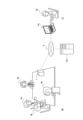
- FIG. 3 is a diagram illustrating an example of the operation of the driving unit 80 in the first electronic device 1 according to one embodiment.
- the driving unit 80 may realize driving about at least one of the driving axes ⁇ , ⁇ , ⁇ , ⁇ , ⁇ , and ⁇ in the first electronic device 1.
- the driving unit 80 may express a negative movement (shaking the head from side to side) of the user of the second electronic device 100 (e.g., participant Mg) by performing driving about the driving axis ⁇ in the first electronic device 1.
- the driving unit 80 may express a positive movement (nodding movement) of the user of the second electronic device 100 (e.g., participant Mg) by performing driving about the driving axis ⁇ in the first electronic device 1.
- the driving unit 80 may express a movement (tilting the head) in which the user of the second electronic device 100 (e.g., participant Mg) is undecided by performing driving about the driving axis ⁇ in the first electronic device 1. Also, for example, the driving unit 80 may express a negative or rejecting movement (shaking the body from side to side) of the user of the second electronic device 100 (e.g., participant Mg) by performing driving about the driving axis ⁇ of the first electronic device 1. Also, for example, the driving unit 80 may express a polite movement (bowing) of the user of the second electronic device 100 (e.g., participant Mg) by performing driving about the driving axis ⁇ of the first electronic device 1. Also, for example, the driving unit 80 may express a movement of the user of the second electronic device 100 (e.g., participant Mg) by performing driving about the driving axis ⁇ of the first electronic device 1.
- the driving unit 80 may express the movement of the eyes E1 and E2 in the face portion Fc of the first electronic device 1 shown in FIG. 3, that is, the line of sight of the user (e.g., participant Mg) of the second electronic device 100.
- the driving unit 80 may express the line of sight of the user (e.g., participant Mg) of the second electronic device 100 by driving at least one of the eyes E1 and E2 in the face portion Fc of the first electronic device 1.
- the driving unit 80 may express the line of sight of the user (e.g., participant Mg) of the second electronic device 100 by driving the movement of at least one of the eyes E1 and E2 in the face portion Fc of the first electronic device 1.
- the driving unit 80 may express the line of sight of the user (e.g., participant Mg) of the second electronic device 100 by moving, for example, at least one of the eyes E1 and E2 in the face portion Fc of the first electronic device 1 in any direction of the arrows shown in FIG. 3.
- the display unit 70 may represent the gaze of the user of the second electronic device 100 (e.g., participant Mg) by displaying, for example, the eyes E1 and E2 in the face portion Fc shown in FIG. 3.
- at least one of the display unit 70 and the drive unit 80 may represent the gaze of the user of the second electronic device 100 (e.g., participant Mg) by displaying at least one of the eyes E1 and E2 of the first electronic device 1.
- various operations expressing the emotions and/or behavior of a human being such as participant Mg can be expressed by displaying the display unit 70 and/or driving the drive unit 80.
- Various known techniques may be used for the operations expressing the emotions and/or behavior of a human being such as participant Mg by displaying the display unit 70 and/or driving the drive unit 80. For this reason, a detailed description of the operations expressing the emotions and/or behavior of a human being such as participant Mg by displaying the display unit 70 and/or driving the drive unit 80 will be omitted.
- the first electronic device 1 according to one embodiment can perform operations expressing the emotions and/or behavior of participant Mg by displaying the display unit 70 and/or driving the drive unit 80.
- the first electronic device 1 may be a dedicated device as described above. Meanwhile, in one embodiment, the first electronic device 1 may include, for example, an audio output unit 60 and a drive unit 80 among the functional units shown in FIG. 2. In this case, the first electronic device 1 may be connected to another electronic device to supplement at least some of the functions of the other functional units shown in FIG. 2.
- the other electronic device may be, for example, a general-purpose smartphone, tablet, phablet, notebook computer (notebook PC or laptop), or computer (desktop).
- the manner in which various actions expressing the emotions and/or behavior of a human being such as participant Mg are expressed by the display unit 70 and/or the drive unit 80 in the first electronic device 1 shown in FIG. 3 may merely be considered as examples that can be envisioned.
- the first electronic device 1 may express various actions expressing the emotions and/or behavior of a human being such as participant Mg by using various configurations and/or operating modes.
- FIG. 4 is a block diagram showing a schematic configuration of the second electronic device 100 shown in FIG. 1.
- the second electronic device 100 may be, for example, an device used by the participant Mg at his/her home RL.
- the above-mentioned first electronic device 1 has a function of outputting the voice and/or video of the participants Ma, Mb, Mc, Md, etc. acquired by the first electronic device 1 when the participants Ma, Mb, Mc, Md, etc. speak to the second electronic device 100.
- the first electronic device 1 can express the gaze of the participant Mg.
- the second electronic device 100 has a function of outputting the voice and/or video of the participant Mg acquired by the second electronic device 100 to the first electronic device 1 when the participant Mg speaks. Furthermore, the second electronic device 100 has a function of outputting the gaze information of the participant Mg acquired by the second electronic device 100 to the first electronic device 1.
- the second electronic device 100 allows the participants Mg to hold a remote conference or video conference even when they are in a location far from the conference room MR. Therefore, the second electronic device 100 is also referred to as an electronic device "used remotely" as appropriate.
- the second electronic device 100 may include a control unit 110, a memory unit 120, a communication unit 130, an imaging unit 140, an audio input unit 150, an audio output unit 160, a display unit 170, and a gaze information acquisition unit 200.
- the control unit 110 may also include, for example, an identification unit 112 and an estimation unit 114.
- the second electronic device 100 may not include at least some of the functional units shown in FIG. 4, or may include components other than the functional units shown in FIG. 4.
- the control unit 110 controls and/or manages the entire second electronic device 100, including each functional unit constituting the second electronic device 100.
- the control unit 110 may basically be configured based on the same concept as the control unit 10 shown in FIG. 2, for example.
- the identification unit 112 and estimation unit 114 of the control unit 110 may also be configured based on the same concept as the identification unit 12 and estimation unit 14 of the control unit 10 shown in FIG. 2, for example.
- the storage unit 120 may function as a memory that stores various types of information.
- the storage unit 120 may store, for example, programs executed in the control unit 110 and results of processing executed in the control unit 110.
- the storage unit 120 may also function as a work memory for the control unit 110.
- the storage unit 120 may be connected to the control unit 110 via a wired and/or wireless connection.
- the storage unit 120 may basically be configured based on the same concept as the storage unit 20 shown in FIG. 2, for example.
- the communication unit 130 has an interface function for wireless and/or wired communication.
- the communication unit 130 may wirelessly communicate with, for example, a communication unit of another electronic device, for example, via an antenna.
- the communication unit 130 may wirelessly communicate with the first electronic device 1 shown in FIG. 1.
- the communication unit 130 may wirelessly communicate with the communication unit 30 of the first electronic device 1.
- the communication unit 130 has a function of communicating with the first electronic device 1.
- the communication unit 130 may wirelessly communicate with the third electronic device 300 shown in FIG. 1.
- the communication unit 130 may wirelessly communicate with the communication unit 330 (described later) of the third electronic device 300.
- the communication unit 130 may have a function of communicating with the third electronic device 300.
- the communication unit 130 may be connected to the control unit 110 in a wired and/or wireless manner.
- the communication unit 130 may basically have a configuration based on the same idea as the communication unit 30 shown in FIG. 2, for example.
- the imaging unit 140 may be configured to include an image sensor that captures images electronically, such as a digital camera.
- the imaging unit 140 may capture images of the interior of the home RL shown in FIG. 1, for example.
- the imaging unit 140 may capture images of participants Mg who join a conference from the home RL shown in FIG. 1, for example.
- the imaging unit 140 may convert the captured images into signals and transmit them to the control unit 110. For this reason, the imaging unit 140 may be connected to the control unit 110 by wire and/or wirelessly.
- the imaging unit 140 may basically be configured based on the same concept as the imaging unit 40 shown in FIG. 2, for example.
- the audio input unit 150 detects (acquires) sounds or voices around the second electronic device 100, including human voices.
- the audio input unit 150 may detect sounds or voices as air vibrations, for example, with a diaphragm, and convert them into an electrical signal.
- the audio input unit 150 may include an acoustic device that converts sounds into an electrical signal, such as an arbitrary microphone.
- the audio input unit 150 may detect (acquire) the voice of the participant Mg in the home RL shown in FIG. 1, for example.
- the voice (electrical signal) detected by the audio input unit 150 may be input to the control unit 110, for example. For this reason, the audio input unit 150 may be connected to the control unit 110 by wire and/or wirelessly.
- the audio input unit 150 may basically be configured based on the same concept as the audio input unit 50 shown in FIG. 2, for example.
- the audio output unit 160 converts an electrical signal (audio signal) supplied from the control unit 110 into sound, and outputs the audio signal as sound or voice.
- the audio output unit 160 may be connected to the control unit 110 by wire and/or wirelessly.
- the audio output unit 160 may be configured to include a device having a function of outputting sound, such as an arbitrary speaker (loudspeaker).
- the audio output unit 160 may output a sound detected by the audio input unit 50 of the first electronic device 1.
- the sound detected by the audio input unit 50 of the first electronic device 1 may be at least one of the voices of the participants Ma, Mb, Mc, and Md in the conference room MR shown in FIG. 1.
- the audio output unit 160 may basically be configured based on the same idea as the audio output unit 60 shown in FIG. 2, for example.
- the display unit 170 may be any display device, such as a Liquid Crystal Display (LCD), an Organic Electro-Luminescence panel, or an Inorganic Electro-Luminescence panel.
- the display unit 170 may basically be configured based on the same concept as the display unit 70 shown in FIG. 2, for example.
- Various data required for display on the display unit 170 may be supplied from, for example, the control unit 110 or the memory unit 120. For this reason, the display unit 170 may be connected to the control unit 110, etc., via a wired and/or wireless connection.
- the display unit 170 may be, for example, a touch screen display equipped with a touch panel function that detects input by contact with the participant Mg's finger or stylus.
- the display unit 170 may display an image based on the video signal transmitted from the first electronic device 1.
- the display unit 170 may display images of participants Ma, Mb, Mc, Md, etc. captured by the first electronic device 1 (its imaging unit 40) as an image based on the video signal transmitted from the first electronic device 1.
- participant Mg shown in FIG. 1 can visually know the state of participants Ma, Mb, Mc, Md, etc. in a conference room MR away from his/her home RL.
- the display unit 170 may directly display images of the participants Ma, Mb, Mc, Md, etc. captured by the first electronic device 1. On the other hand, the display unit 170 may display images (e.g., avatars) that characterize the participants Ma, Mb, Mc, Md, etc.
- images e.g., avatars
- the gaze information acquisition unit 200 acquires gaze information of the user of the second electronic device 100 (e.g., participant Mg).
- the gaze information acquisition unit 200 may acquire gaze information of the user of the second electronic device 100, such as the gaze of the user of the second electronic device 100, the direction of the gaze, and/or the movement of the gaze.
- the gaze information acquisition unit 200 may have a function of tracking the movement of the gaze of the user of the second electronic device 100 (e.g., participant Mg), such as an eye tracker.
- the gaze information acquisition unit 200 may be any component capable of acquiring gaze information of the user of the second electronic device 100, such as the gaze of the user of the second electronic device 100, the direction of the gaze, and/or the movement of the gaze.
- the second electronic device 100 may acquire gaze information of a user (e.g., participant Mg) of the second electronic device 100 based on the eye movement of the user captured by the imaging unit 140.
- the second electronic device 100 may not include the gaze information acquisition unit 200, or the imaging unit 140 may also function as the gaze information acquisition unit 200.
- the gaze information acquired by the gaze information acquisition unit 200 may be input to the control unit 110, for example. For this reason, the gaze information acquisition unit 200 may be connected to the control unit 110 via a wired and/or wireless connection.
- the second electronic device 100 may be a dedicated device as described above. Meanwhile, in one embodiment, the second electronic device 100 may include some of the functional units shown in FIG. 4, for example. In this case, the second electronic device 100 may be connected to another electronic device to supplement at least some of the functions of the other functional units shown in FIG. 4.
- the other electronic device may be, for example, a general-purpose smartphone, tablet, phablet, notebook computer (notebook PC or laptop), or computer (desktop), etc.
- the second electronic device 100 may be a smartphone or a laptop computer.
- the second electronic device 100 may be a smartphone or a laptop computer with an application (program) installed for linking with the first electronic device 1.
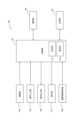
- FIG. 5 is a block diagram showing a schematic configuration of the third electronic device 300 shown in FIG. 1. An example of the configuration of the third electronic device 300 according to an embodiment will be described below.
- the third electronic device 300 may be installed in a location other than the participant Mg's home RL and the conference room MR, as shown in FIG. 1.
- the third electronic device 300 may be installed in the participant Mg's home RL or nearby, or in the conference room MR or nearby.
- the first electronic device 1 has a function of transmitting the audio and/or video data of the participants Ma, Mb, Mc, Md, etc. acquired by the first electronic device 1 to the third electronic device 300 when the participants Ma, Mb, Mc, Md, etc. speak.
- the third electronic device 300 may transmit the audio and/or video data received from the first electronic device 1 to the second electronic device 100.
- the second electronic device 100 also has a function of transmitting the audio and/or video data of the participant Mg acquired by the second electronic device 100 to the third electronic device 300 when the participant Mg speaks.
- the third electronic device 300 may transmit the audio and/or video data received from the second electronic device 100 to the first electronic device 1. In this way, the third electronic device 300 may have a function of relaying between the first electronic device 1 and the second electronic device 100.
- the third electronic device 100 is also referred to as a "server" as appropriate.
- the third electronic device 300 may include a control unit 310, a storage unit 320, and a communication unit 330.
- the control unit 310 may also include, for example, an identification unit 312 and an estimation unit 314.
- the third electronic device 300 may not include at least some of the functional units shown in FIG. 5, or may include components other than the functional units shown in the figure.
- the control unit 310 controls and/or manages the entire third electronic device 300, including each functional unit constituting the third electronic device 300.
- the control unit 310 may basically be configured based on the same concept as the control unit 10 shown in FIG. 2, for example.
- the identification unit 312 and estimation unit 314 of the control unit 310 may also be configured based on the same concept as the identification unit 12 and estimation unit 14 of the control unit 10 shown in FIG. 2, for example.
- the storage unit 320 may function as a memory that stores various types of information.
- the storage unit 320 may store, for example, programs executed in the control unit 310 and results of processing executed in the control unit 310.
- the storage unit 320 may also function as a work memory for the control unit 310.
- the storage unit 320 may be connected to the control unit 310 via a wired and/or wireless connection.
- the storage unit 320 may basically be configured based on the same concept as the storage unit 20 shown in FIG. 2, for example.
- the communication unit 330 has an interface function for wireless and/or wired communication.
- the communication unit 330 may wirelessly communicate with, for example, a communication unit of another electronic device, for example, via an antenna.
- the communication unit 330 may wirelessly communicate with the first electronic device 1 shown in FIG. 1.
- the communication unit 330 may wirelessly communicate with the communication unit 30 of the first electronic device 1.
- the communication unit 330 has a function of communicating with the first electronic device 1.
- the communication unit 330 may wirelessly communicate with the second electronic device 100 shown in FIG. 1.
- the communication unit 330 may wirelessly communicate with the communication unit 130 of the second electronic device 100.
- the communication unit 330 may have a function of communicating with the second electronic device 100. As shown in FIG. 5, the communication unit 330 may be connected to the control unit 310 in a wired and/or wireless manner. The communication unit 330 may basically be configured based on the same idea as the communication unit 30 shown in FIG. 2.
- the third electronic device 300 may be, for example, a specially designed device.
- the third electronic device 300 may include, for example, some of the functional units shown in FIG. 5.
- the third electronic device 300 may be connected to other electronic devices to supplement at least some of the functions of the other functional units shown in FIG. 5.
- the other electronic devices may be, for example, devices such as a general-purpose computer or server.
- the third electronic device 300 may be, for example, a relay server, a web server, or an application server.
- the first electronic device 1 is installed in the conference room MR and acquires video and/or audio of at least one of the participants Ma, Mb, Mc, and Md.
- the video and/or audio acquired by the first electronic device 1 is transmitted to the second electronic device 100 installed in the home RL of the participant Mg.
- the second electronic device 100 outputs the video and/or audio of at least one of the participants Ma, Mb, Mc, and Md acquired by the first electronic device 1. This allows the participant Mg to recognize the video and/or audio of at least one of the participants Ma, Mb, Mc, and Md.
- the second electronic device 100 is installed in the home RL of the participant Mg and acquires the voice of the participant Mg.
- the second electronic device 100 also acquires information on the gaze of the participant Mg.
- the voice and/or gaze information acquired by the second electronic device 100 is transmitted to the first electronic device 1 installed in the conference room MR.
- the first electronic device 1 outputs the voice of the participant Mg received from the second electronic device 100.
- at least one of the participants Ma, Mb, Mc, and Md can hear the voice of the participant Mg.
- the first electronic device 1 also expresses the gaze of the participant Mg based on the gaze information of the participant Mg received from the second electronic device 100.
- the second electronic device 100 may acquire an image of the participant Mg.
- the image acquired by the second electronic device 100 may be transmitted to the first electronic device 1 installed in the conference room MR.
- the first electronic device 1 may output the video of the participant Mg received from the second electronic device 100.
- FIG. 6 is a sequence diagram explaining the basic operation of the system according to the embodiment described above.
- FIG. 6 is a diagram showing the exchange of data and the like between the first electronic device 1, the second electronic device 100, and the third electronic device 300.
- the basic operation when a remote conference or video conference is held using the system according to the embodiment will be explained with reference to FIG. 6.
- the first electronic device 1 used locally may be used by the first user.
- the first user may be, for example, at least one of the participants Ma, Mb, Mc, and Md shown in FIG. 1 (hereinafter also referred to as a local user).
- the second electronic device 100 used remotely may be used by the second user.
- the second user may be, for example, the participant Mg shown in FIG. 1 (hereinafter also referred to as a remote user).
- the operation performed by the first electronic device 1 may be, in more detail, performed by, for example, the control unit 10 of the first electronic device 1.
- the operation performed by the control unit 10 of the first electronic device 1 may be referred to as the operation performed by the first electronic device 1.
- the operation performed by the second electronic device 100 may be, in more detail, performed by, for example, the control unit 110 of the second electronic device 100.
- the operation performed by the control unit 110 of the second electronic device 100 may be referred to as the operation performed by the second electronic device 100.
- the operations performed by the third electronic device 300 may be more specifically performed by, for example, the control unit 310 of the third electronic device 300.
- the operations performed by the control unit 310 of the third electronic device 300 may be referred to as operations performed by the third electronic device 300.
- the first electronic device 1 acquires at least one of the video and audio of the first user (e.g., at least one of the participants Ma, Mb, Mc, and Md) (step S1). Specifically, in step S1, the first electronic device 1 may capture the video of the first user using the imaging unit 40 and acquire (or detect) the audio of the first user using the audio input unit 50. Next, the first electronic device 1 encodes at least one of the video and audio of the first user (step S2). In step S2, encoding may mean compressing the video and/or audio data according to a predetermined rule and converting it into a format according to the purpose, including encryption. The first electronic device 1 may perform various known encoding methods, such as software encoding or hardware encoding.
- the first electronic device 1 transmits the encoded video and/or audio data to the third electronic device 300 (step S3). Specifically, in step S3, the first electronic device 1 transmits the video and/or audio data from the communication unit 30 to the communication unit 330 of the third electronic device 300. Also in step S3, the third electronic device 300 receives the video and/or audio data transmitted from the communication unit 30 of the first electronic device 1 via the communication unit 330.
- the third electronic device 300 transmits the encoded video and/or audio data received from the communication unit 30 to the second electronic device 100 (step S4). Specifically, in step S4, the third electronic device 300 transmits the video and/or audio data from the communication unit 330 to the communication unit 130 of the second electronic device 100. Also, in step S4, the second electronic device 100 receives the video and/or audio data transmitted from the communication unit 330 of the third electronic device 300 via the communication unit 130.
- step S5 decodes the encoded video and/or audio data received from the communication unit 330 (step S5).
- decoding may mean returning the format of the encoded video and/or audio data to its original format.
- the second electronic device 100 may perform various known decoding methods, such as software encoding or hardware encoding.
- the second electronic device 100 presents at least one of the video and audio of the first user (e.g., at least one of participants Ma, Mb, Mc, and Md) to the second user (e.g., participant Mg) (step S6).
- the second electronic device 100 may display the video of the first user on the display unit 170 and output the audio of the first user from the audio output unit 160.
- a second user e.g., participant Mg
- a first user e.g., at least one of participants Ma, Mb, Mc, and Md
- the above describes a manner in which the first electronic device 1 transmits video and/or audio of the first user to the second electronic device 100 via the third electronic device 300.
- the second electronic device 100 can transmit audio and/or gaze information of the second user to the first electronic device 1 via the third electronic device 300.
- the second electronic device 100 acquires at least one of the voice and gaze information of the second user (e.g., participant Mg) (step S11). Specifically, in step S11, the second electronic device 100 may acquire (or detect) the voice of the second user by the voice input unit 150. Also, in step S11, the second electronic device 100 may acquire gaze information of the second user by the gaze information acquisition unit 200. Next, the second electronic device 100 encodes at least one of the voice and gaze information of the second user (step S12).
- the second electronic device 100 transmits the encoded voice and/or gaze data to the third electronic device 300 (step S13). Specifically, in step S13, the second electronic device 100 transmits the voice and/or gaze data from the communication unit 130 to the communication unit 330 of the third electronic device 300. Also in step S13, the third electronic device 300 receives the voice and/or gaze data transmitted from the communication unit 130 of the second electronic device 100 via the communication unit 330.
- the third electronic device 300 transmits the encoded voice and/or gaze data received from the communication unit 130 to the first electronic device 1 (step S14). Specifically, in step S14, the third electronic device 300 transmits the voice and/or gaze data from the communication unit 330 to the communication unit 30 of the first electronic device 1. Also, in step S14, the first electronic device 1 receives the voice and/or gaze data transmitted from the communication unit 330 of the third electronic device 300 via the communication unit 30.
- the first electronic device 1 decodes the encoded voice and/or gaze data received from the communication unit 330 (step S15).
- the first electronic device 1 presents at least one of the voice and/or gaze of the second user (e.g., participant Mg) to the first user (e.g., at least one of participants Ma, Mb, Mc, and Md) (step S16). Specifically, in step S16, the first electronic device 1 may output the voice of the second user from the audio output unit 60. Also, in step S16, the first electronic device 1 may express the gaze of the second user by driving the drive unit 80.
- a first user e.g., at least one of participants Ma, Mb, Mc, and Md
- a second user e.g., participant Mg
- step S1 to step S6 and the operations from step S11 to step S16 may be executed in the reverse order. That is, the operations from step S11 to step S16 may be executed first, and then the operations from step S1 to step S6. Furthermore, the operations from step S1 to step S6 and the operations from step S11 to step S16 may be executed simultaneously, or may be executed so that they at least partially overlap.
- the results of eye tracking of the gaze of the user (participant Mg) of the second electronic device 100 by the gaze information acquisition unit 200 are always reflected in the gaze expression by the drive unit 80 of the first electronic device 1.
- the acquisition of gaze information by the gaze information acquisition unit 200 of the second electronic device 100 and/or the gaze expression by the drive unit 80 of the first electronic device 1 cannot keep up with the actual gaze movement of the participant Mg.
- the frequency of the gaze movement by the drive unit 80 of the first electronic device 1 becomes too high. If the frequency of the gaze movement by the drive unit 80 of the first electronic device 1 becomes too high, it may cause discomfort to the participants Ma, Mb, Mc, and Md who visually observe the movement of the first electronic device 1.
- the driver 80 of the first electronic device 1 may express the gaze when the actual gaze of the participant Mg is fixed for a predetermined time, such as three seconds. However, even with this type of control, the driver 80 of the first electronic device 1 does not express the gaze until the predetermined time, such as three seconds, has elapsed, making it difficult to improve the real-time nature of the gaze expression.
- the first electronic device 1 may automatically express the gaze. For example, the first electronic device 1 may identify participants Ma, Mb, Mc, Md, etc., and control the drive unit 80 to drive the gaze toward the identified participants. However, in such control, the gaze of the user of the second electronic device 100 (participant Mg) is not reflected, and participants Ma, Mb, Mc, Md, etc. cannot visually recognize the gaze movement of participant Mg.
- a system realizes a situation in which the gaze of a user of an electronic device used remotely is properly recognized by a user of an electronic device used locally.
- FIG. 7 is a flowchart illustrating a characteristic operation of the system according to an embodiment.
- the operation shown in FIG. 7 may be executed by at least one of the first electronic device 1, the second electronic device 100, and the third electronic device 300 included in the system according to an embodiment.
- the operation shown in FIG. 7 will be described as being executed by the control unit 310 of the third electronic device 300.
- the operation shown in FIG. 7 may be executed by the control unit 10 of the first electronic device 1, or may be executed by the control unit 110 of the second electronic device 100.
- the operations shown in FIG. 7 may be executed in parallel with the operations shown in FIG. 6.
- the operations shown in FIG. 7 may also be executed so as to interrupt the operations shown in FIG. 6 while they are being performed.
- the operations shown in FIG. 6 may also be executed so as to interrupt the operations shown in FIG. 7 while they are being performed.
- FIG. 7 a description will be given of characteristic operations when a remote conference or video conference is held using a system according to one embodiment.
- the encoding and decoding of data described in FIG. 5 may use known technology. For this reason, a description of the encoding and decoding of data will be omitted in FIG. 7.
- a description of content that is the same or similar to that already described in FIG. 6 may be simplified or omitted as appropriate.
- the first electronic device 1 is assumed to be ready to acquire at least one of the video and audio of the first user (e.g., at least one of the participants Ma, Mb, Mc, and Md).
- the first electronic device 1 is also assumed to be ready to transmit at least one of the video and audio of the first user that it has acquired to the third electronic device 300.
- the first electronic device 1 is assumed to be ready to receive various types of information transmitted from the third electronic device 300.
- the second electronic device 100 is assumed to be ready to acquire at least one of the voice and gaze information of the second user (e.g., participant Mg). Also, the second electronic device 100 is assumed to be ready to transmit at least one of the voice and gaze information of the second user acquired to the third electronic device 300. Furthermore, the second electronic device 100 is assumed to be ready to receive various types of information transmitted from the third electronic device 300.
- the control unit 310 determines whether or not a voice spoken by any of the first users has been acquired by the first electronic device 1 (step S101).
- the first user may be, for example, at least one of the participants Ma, Mb, Mc, and Md, and any of the first users may be, for example, participant Mc.
- the first electronic device 1 may acquire the voice when any of the first users (participant Mc in this case) starts a conversation, for example, and transmit it to the third electronic device 300.
- the control unit 310 identifies a speaker among the first users who is speaking (currently speaking) based on at least one of the video and audio of the first user acquired by the first electronic device 1 (step S102). That is, in step S102, the control unit 310 may identify a speaker (e.g., one or more) among a possible plurality of first users. Here, the control unit 310 may identify participant Mc as the speaker based on the video of multiple participants including participant Mc and the audio of participant Mc acquired by the first electronic device 1.
- the control unit 310 may use various techniques to identify the speaker of the first user based on at least one of the video and audio of the first user. For example, the control unit 310 may identify the speaker of the first user by performing person detection from the video (image) of the first user and estimating the direction of the sound source from the audio of the first user. In this case, the direction of the sound source may be estimated in the section where the audio of the first user is detected. The control unit 310 may also perform person detection from the video (image) of the first user and determine whether the first user is speaking from the video (image) of the first user's mouth. In this case, the control unit 310 may also appropriately perform processing such as lip reading from the video (image) of the first user's mouth.
- the control unit 310 may also perform person detection from the video (image) of the first user and identify the speaker of the first user by detecting the body movement (behavior) of the first user. As described above, the control unit 310 may identify the speaker of the first user by any process based on at least one of the video and audio of the first user.
- control unit 310 identifies the position of the speaker in the image of the first user acquired by the first electronic device 1 (step S103).
- step S102 the control unit 310 identified the speaker from among the possible multiple first users.
- step S103 the control unit 310 identifies the position of the speaker (here, participant Mc) in the image containing the possible multiple first users.
- the control unit 310 may identify the coordinates of the position of the speaker (here, participant Mc) in the image of the first user.
- steps S102 and S103 may be executed by the control unit 310, for example, by the identification unit 112.
- control unit 310 determines whether or not gaze information of the second user (participant Mg) has been acquired by the second electronic device 100 (step S104). The process performed when gaze information of the second user has not been acquired in step S104 will be described later.
- step S104 the control unit 310 estimates where the second user's gaze is directed in the image of the first user (step S105). That is, in step S105, the control unit 310 estimates (acquires) the position where the second user's gaze is directed in the image of the first user, based on the second user's gaze information acquired by the second electronic device 100.
- the position (coordinates) in the image of the first user and the position of the direction of the gaze of the second user may be associated with each other.
- the position (two-dimensional coordinates) in the image of the first user may be converted into a position (three-dimensional coordinates) in real space of the direction of the gaze of the second user.
- the position (three-dimensional coordinates) in real space of the direction of the gaze of the second user may be converted into a position (two-dimensional coordinates) in the image of the first user.
- step S105 may be executed by the control unit 310, for example, by the estimation unit 114.
- control unit 310 determines whether the position identified in step S103 and the position estimated in step S105 are within a predetermined distance (step S106). That is, the control unit 310 determines whether the position of the speaker in the video of the first user and the position in the video of the first user where the gaze of the second user is directed are within a predetermined distance. When there are multiple speakers, the control unit 310 may individually determine whether the position of each speaker in the video of the first user and the position in the video of the first user where the gaze of the second user is directed are within a predetermined distance.
- step S106 When the determination in step S106 is positive (YES in step S106), it means that the position where the second user's gaze is directed is relatively close to the position of the speaker. That is, in this case, it may be determined that the second user is directing his/her gaze at the speaker. Therefore, in this case, the control unit 310 may control the first electronic device to indicate that the second user's gaze is directed at the speaker (step S107). That is, in this case, the control unit 310 may drive the drive unit 80 by controlling the first electronic device 1 so that the gaze of the first electronic device 1 is directed (facing) the speaker.
- the control unit 310 may control the first electronic device to indicate that the second user's gaze is directed at the speaker who is closest to the position where the second user's gaze is directed. In this way, in a system according to one embodiment, the control unit 310 may control the first electronic device 1 to indicate the position to which the second user's gaze is most directed in the video of the first user.
- step S106 determines whether the position towards which the second user's gaze is directed is relatively far from the position of the speaker. That is, in this case, it may be determined that the second user is not directing his/her gaze at the speaker. Therefore, in this case, the control unit 310 may control the first electronic device 1 to indicate that the second user's gaze is not directed at the speaker (step S108). That is, in this case, the control unit 310 may control the first electronic device 1 to drive the drive unit 80 so that the gaze of the first electronic device 1 is not directed at (not directly facing) the speaker.
- control unit 310 may perform the operation of step S108.
- participant Mc in the conference room MR speaks, participant Mg in the home RL can recognize the state in which participant Mc is speaking via the display unit 170 of the second electronic device 100.
- participant Mg in the home RL turns his/her gaze on participant Mc who is speaking on the display unit 170 of the second electronic device 100.
- the gaze of the first electronic device 1 in the conference room MR is directed at participant Mc. Therefore, participant Mc can recognize the situation in which participant Mg in the home RL is turning his/her gaze at participant Mc.
- participant Mc can recognize the situation in which participant Mg in the home RL is turning his/her gaze at participant Mc.
- other participants in the conference room MR such as participant Ma, participant Mb, and/or participant Md, can also recognize the situation in which participant Mg in the home RL is turning his/her gaze at participant Mc.
- the system according to one embodiment can control the direction of gaze of the first electronic device 1 using the speaker's speech as a trigger. Therefore, the system according to one embodiment can control the gaze of a participant who is participating in a remote conference at home, for example, while reflecting the gaze of the participant on the first electronic device 1 to an extent that does not cause discomfort to the other participants. Furthermore, the system according to one embodiment can control the first electronic device 1 to instantly direct its gaze in response to the speaker's speech. Therefore, the system according to one embodiment can facilitate communication between multiple locations.
- the control unit 310 may identify the position in real space of the speaker of the first user (e.g., participant Mc) based on the position of the first electronic device 1 in real space (e.g., conference room MR). In this way, the position of the speaker of the first user can be identified more accurately. Then, if the determination in step S106 is positive (YES in step S106), the control unit 130 may control the line of sight of the second user (participant Mg) represented by the first electronic device 1 to be directed toward the position of the speaker (participant Mc) in real space.
- the control unit 130 may control the line of sight of the second user (participant Mg) represented by the first electronic device 1 to be directed toward the position of the speaker (participant Mc) in real space.
- step S103 of FIG. 7 when the control unit 310 (identification unit 312) identifies the position of the speaker of the first user, the control unit 310 (identification unit 312) may determine that the positions of the candidate speakers are each areas having a predetermined area in the image of the first user. In other words, the identification unit 312 may identify the speaker of the first user depending on whether the position of the speaker estimated based on the voice of the first user is included in each area of the first user that is set based on each position of the first user in the image of the first user.
- FIG. 8 is a flowchart illustrating the characteristic operations of the system according to one embodiment.
- the operations shown in FIG. 8 are partial modifications of the operations shown in FIG. 7. Therefore, descriptions that are the same or similar to those already explained in FIG. 7 will be omitted as appropriate.
- the control unit 310 identifies each first user based on the video of the first user acquired by the first electronic device 1 (step S201). That is, in step S201, the control unit 310 may identify each of the first users, of which there may be multiple. Here, the control unit 310 may identify, for example, participant Ma, participant Mb, participant Mc, and participant Md, based on the video of multiple participants including participant Mc acquired by the first electronic device 1.
- the control unit 310 may use various techniques to identify each first user based on the video of the first user. For example, the control unit 310 may perform person detection from the video (image) of the first user to identify each first user. The control unit 310 may identify each first user by any processing based on the video of the first user. Furthermore, when the voice of the first user can be acquired, the control unit 310 may also identify each first user by taking into account an estimation of the direction of the sound source from the voice of the first user. The control unit 310 may identify each first user by any processing based on at least one of the video and voice of the first user.
- control unit 310 identifies the position of each first user in the image of the first user acquired by the first electronic device 1 (step S202).
- step S201 the control unit 310 identified the speaker from among multiple possible first users.
- step S202 the control unit 310 identifies the position of each first user in the image including multiple possible first users.
- the control unit 310 may identify the coordinates of the position of each first user (here, for example, participant Ma, participant Mb, participant Mc, and participant Md) in the image of the first users.
- steps S201 and S202 may be executed by the control unit 310, for example, by the identification unit 112.
- control unit 310 determines whether or not gaze information of the second user (participant Mg) has been acquired by the second electronic device 100 (step S104).
- the process performed in step S104 may be similar to step S104 shown in FIG. 7. The process performed when gaze information of the second user has not been acquired will be described later.
- step S105 the control unit 310 estimates where the second user's gaze is directed in the image of the first user (step S105). That is, in step S105, the control unit 310 estimates (acquires) the position where the second user's gaze is directed in the image of the first user based on the second user's gaze information acquired by the second electronic device 100.
- the process performed in step S105 may be the same as step S105 shown in FIG. 7.
- control unit 310 determines whether any of the positions identified in step S202 and the position estimated in step S105 are within a predetermined distance (step S203). That is, the control unit 310 determines whether any of the positions of the first user in the first user's video and the position to which the second user's gaze is directed in the first user's video are within a predetermined distance.
- step S203 If the determination in step S203 is positive (YES in step S203), this means that the position to which the second user is looking is relatively close to the position of one of the first users. In other words, in this case, it may be determined that the second user is looking at one of the first users.
- step S203 determines whether the voice of the second user has been acquired by the second electronic device 100 (step S204).
- the second electronic device 100 may acquire the voice when the second user starts a conversation, for example, and transmit the voice to the third electronic device 300.
- the control unit 310 may control the first electronic device to indicate that the second user's gaze is directed toward one of the first users based on the voice of the second user (step S205). That is, in this case, the control unit 310 may control the first electronic device 1 to drive the drive unit 80 so that the gaze of the first electronic device 1 is directed toward (facing) one of the first users.
- step S203 determines whether the position towards which the second user's gaze is directed is relatively far from the positions of any of the first users. That is, in this case, it may be determined that the second user is not directing his/her gaze towards any of the first users. Therefore, in this case, the control unit 310 may control the first electronic device 1 to indicate that the gaze of the second user is not directed towards any of the first users (step S206). That is, in this case, the control unit 310 may control the first electronic device 1 to drive the drive unit 80 so that the gaze of the first electronic device 1 is not directed towards (not directly facing) any of the first users.
- step S104 if the second user's gaze information is not acquired in step S104, the second user's gaze cannot be reflected in the first electronic device 1. Therefore, in this case too, the control unit 310 may perform the operation of step S206. In addition, if the second user's voice is not acquired in step S204, the second user's gaze does not have to be reflected in the first electronic device 1. Therefore, in this case too, the control unit 310 may perform the operation of step S206.
- the participant Mg in the home RL can recognize the participants Ma, Mb, Mc, and Md through the display unit 170 of the second electronic device 100. Assume that the participant Mg in the home RL starts speaking to the participant Mc while looking at the participant Mc on the display unit 170 of the second electronic device 100. In this case, in the conference room MR, the first electronic device 1 turns its gaze to the participant Mc in response to the speech of the participant Mg in the home RL. Therefore, the participant Mc can recognize the situation in which the participant Mg in the home RL is speaking while looking at the participant Mc. In addition, other participants in the conference room MR, such as the participant Ma, the participant Mb, and/or the participant Md, can also recognize the situation in which the participant Mg in the home RL is speaking while looking at the participant Mc.
- the system may include, for example, the first electronic device 1, the second electronic device 100, and the control unit 310.
- the first electronic device 1 acquires an image of at least one first user.
- the second electronic device 100 outputs the image of the first user to the second user and acquires information on the line of sight of the second user.
- the control unit 310 controls the position of the line of sight of the second user in the image of the first user so that it is indicated by the first electronic device 1.
- the system according to one embodiment can control the direction of the line of sight of the first electronic device 1 using the speech of a speaker as a trigger.
- the system according to one embodiment can control the line of sight of a participant participating in a remote conference at home or the like while reflecting the line of sight of the participant on the first electronic device 1 to a degree that does not cause discomfort to other participants. Furthermore, the system according to one embodiment can control the first electronic device 1 to immediately direct its line of sight in response to the speech of the speaker. Therefore, the system according to one embodiment can facilitate communication between multiple locations.
- the control unit 310 may identify the position of each of the first users in real space based on the position of the first electronic device 1 in real space (e.g., conference room MR). In this way, the position of each of the first users can be identified more accurately. Then, if the determination in step S203 is positive (YES in step S203), the control unit 130 may control the line of sight of the second user (participant Mg) represented by the first electronic device 1 to be directed toward the position of one of the first users in real space.
- the control unit 130 may control the line of sight of the second user (participant Mg) represented by the first electronic device 1 to be directed toward the position of one of the first users in real space.
- the embodiments of the present disclosure can also be realized as a method, a program executed by a processor or the like included in the device, or a storage medium or storage medium on which a program is recorded. It should be understood that these are also included in the scope of the present disclosure.
- control unit 310 may execute the process of step S205 instead of the process of step S204 shown in FIG. 8. In this case, even if the second user is not speaking, the control unit 310 can control the first electronic device 1 to drive the drive unit 80 so that the line of sight of the first electronic device 1 is directed (facing) towards one of the first users.
- control unit 310 makes the determination using a predetermined distance in step S106 shown in FIG. 7 and step S203 shown in FIG. 8.
- control unit 310 may identify a speaker who satisfies other conditions or a position (coordinates) in the video of the first user as the position toward which the second user's gaze is directed.
- control unit 310 in order for the control unit 310 to execute the process of step S105, in addition to associating the position (coordinates) in the image of the first user with the position to which the gaze of the second user is directed, other control may also be performed. In this case, the control unit 310 may further associate, for example, the time or number of times that the gaze of the second user is directed to the position (coordinates) in the image of the first user. Then, instead of the determination using a predetermined distance in step S106 or step S203, the control unit 310 may execute the following process.
- control unit 310 may determine the position (coordinates) in the image of the first user to which the gaze of the second user is directed for the longest time or the most number of times during a predetermined period in the past up to the time when the process is executed. In this case, the control unit 310 may execute the process in step S107 or step S205 with the position determined as described above as the position to be used for controlling the first electronic device.
- control unit 310 may execute the following process to execute the process of step S105. That is, the control unit 310 may not only associate the position (coordinates) in the image of the first user with the position of the second user's gaze, but may also further associate an evaluation value according to the time or number of times that the gaze of the second user was directed to the position (coordinates) in the image of the first user. Then, instead of the determination using a predetermined distance in step S106 or step S203, the control unit 310 may execute the following process.
- control unit 310 may find the position (coordinates) in the image of the first user that has the highest evaluation value among the evaluation values associated with the positions (coordinates) in the image of the first user during a predetermined period in the past up to the time when the process is executed. In this case, the control unit 310 may execute the process in step S107 or step S205 as the position to be used for controlling the first electronic device.
- the evaluation value may be set highest for the position (coordinates) in the video of the first user that corresponds to the position of the gaze of the second user, and the evaluation values assigned to the coordinates around this position may gradually decrease as the distance from the position increases.
- the video of the first user may be divided into a number of regions, and an evaluation value may be associated with each divided region.
- an evaluation value according to the position of the first user and/or the behavior (movement) of the first user that attracts the attention of the second user may be added to the above-mentioned evaluation value.
- an evaluation value may be set in advance for each of the actions such as the position of the first user or the speaker, the speaker's speech volume, the physical movement of the first user, the line of sight of the first user, and/or the facial movement of the first user. Then, the evaluation value based on the position and/or the behavior of the first user may be added to the evaluation value of the corresponding position (coordinates) in the video of the first user.
- the control unit 310 may execute the following process. That is, the control unit 310 may determine the position (coordinates) in the video of the first user that has the highest evaluation value among the evaluation values associated with the positions (coordinates) in the video of the first user during a predetermined period in the past from the time of executing the process. In this case, the control unit 310 may execute processing in step S107 or step S205 as a position to be used for controlling the first electronic device.
- the evaluation value may be set highest for the position (coordinates) in the image of the first user corresponding to the position and behavior of the first user, and evaluation values may be assigned to the coordinates around this position that gradually decrease as they move away from the position.
- the control unit 310 may control the position of the gaze of the second user to be indicated by the first electronic device 1 based on various conditions. For example, the control unit 310 may control the position of the gaze of the second user to be indicated by the first electronic device 1 based on the position of the first user in the image of the first user, at least one of the actions of the first user, and the position to which the gaze of the second user is most directed in the image of the first user.
- the above-described embodiments are not limited to implementation as a system.
- the above-described embodiments may be implemented as a control method for a system, or as a program executed in a system.
- the above-described embodiments may be implemented as at least one of the first electronic device 1, the second electronic device 100, and the third electronic device 300.
- the above-described embodiments may be implemented as a control method for at least one of the first electronic device 1, the second electronic device 100, and the third electronic device 300.
- the above-described embodiments may be implemented as a program executed by at least one of the first electronic device 1, the second electronic device 100, and the third electronic device 300, or as a storage medium or recording medium on which the program is recorded.
- the above-described embodiment may be implemented as the first electronic device 1.
- the first electronic device 1 may be configured to be able to communicate with the second electronic device 100.
- the first electronic device 1 may include an acquisition unit, an identification unit, an estimation unit, and a control unit.
- the acquisition unit acquires an image of at least one first user.
- the identification unit identifies each first user based on the image of the first user acquired by the acquisition unit, and identifies the position of each first user in the image of the first user acquired by the acquisition unit.
- the estimation unit estimates the position of the second user's gaze direction in the image of the first user based on information on the gaze of the second user acquired by the second electronic device.
- the control unit determines whether or not the position of any of the first users in the image of the first user and the position of the second user's gaze direction in the image of the first user are within a predetermined distance. Depending on the determination result, the control unit controls the first electronic device 1 to indicate that the gaze of the second user is directed toward any of the first users based on the voice of the second user acquired by the second electronic device 200.
Landscapes
- Engineering & Computer Science (AREA)
- Multimedia (AREA)
- Signal Processing (AREA)
- Computational Linguistics (AREA)
- Health & Medical Sciences (AREA)
- Audiology, Speech & Language Pathology (AREA)
- Human Computer Interaction (AREA)
- Physics & Mathematics (AREA)
- Acoustics & Sound (AREA)
- Two-Way Televisions, Distribution Of Moving Picture Or The Like (AREA)
Abstract
This system comprises: a first electronic device that acquires video of at least one first user; a second electronic device that outputs the video of the first user to a second user, and acquires information about the line of sight of the second user; and a control unit that performs control so that the first electronic device indicates a position to which the line of sight of the second user in the video of the first user is directed.
Description
本出願は、2022年10月7日に日本国に特許出願された特願2022-162777の優先権を主張するものであり、この先の出願の開示全体を、ここに参照のために取り込む。
This application claims priority to patent application No. 2022-162777, filed in Japan on October 7, 2022, the entire disclosure of which is incorporated herein by reference.
本開示は、システム、電子機器、システムの制御方法、及びプログラムに関する。
This disclosure relates to a system, an electronic device, a method for controlling the system, and a program.
近年、Web会議又はビデオ会議などのような、いわゆるリモート会議が実施される機会が増えている。リモート会議においては、複数の場所に存在する参加者のコミュニケーションを実現する電子機器(又は電子機器を含むシステム)が使用される。例えば、あるオフィスにおいて会議が行われる際に、会議の参加者の少なくとも1人が、遠隔地の自宅でリモート会議を行う場面を想定する。この場合、オフィスにおける会議の音声及び/又は映像は、例えばオフィスに設置された電子機器によって取得されて、例えば参加者の自宅に設置された電子機器に送信される。また、参加者の自宅における音声及び/又は映像は、例えば参加者の自宅に設置された電子機器によって取得されて、例えばオフィスに設置された電子機器に送信される。このような電子機器によれば、参加者全員が同じ場所に参集しなくても、会議を行うことができる。
In recent years, so-called remote conferences, such as web conferences or video conferences, have become more common. In remote conferences, electronic devices (or systems including electronic devices) are used to enable communication between participants in multiple locations. For example, consider a situation in which a conference is held in an office, and at least one of the conference participants holds the remote conference at his or her home in a remote location. In this case, audio and/or video of the conference in the office is acquired by, for example, an electronic device installed in the office, and transmitted to, for example, an electronic device installed in the participant's home. Also, audio and/or video at the participant's home is acquired by, for example, an electronic device installed in the participant's home, and transmitted to, for example, an electronic device installed in the office. Such electronic devices allow a conference to be held without all participants gathering in the same place.
上述のようなリモート会議に応用され得る技術は、種々提案されている。例えば特許文献1は、スピーカが出力する指向性を有する音の出力範囲を表わす図形を、カメラが撮像した画像と重ねて表示する装置を開示している。この装置によれば、指向性を有する音の出力範囲を視覚的に把握することができる。また、例えば、特許文献2は、離れた所にいる話し手と聞き手が会話を行う際、話し手の側に聞き手ロボットを付設し、聞き手の側に話し手ロボットを付設するシステムを開示している。
Various technologies that can be applied to remote conferences such as those described above have been proposed. For example, Patent Document 1 discloses a device that displays a graphic that represents the output range of directional sound output by a speaker, superimposed on an image captured by a camera. This device makes it possible to visually grasp the output range of directional sound. Furthermore, for example, Patent Document 2 discloses a system in which, when a speaker and a listener in separate locations are engaged in a conversation, a listener robot is attached to the speaker's side, and a speaker robot is attached to the listener's side.
一実施形態に係るシステムは、
少なくとも1人の第1ユーザの映像を取得する第1電子機器と、
前記第1ユーザの映像を第2ユーザに出力し、前記第2ユーザの視線の情報を取得する第2電子機器と、
前記第1ユーザの映像における、前記第2ユーザの視線が向く先の位置を、前記第1電子機器が示すように制御する制御部と、
を含む。 In one embodiment, the system includes:
a first electronic device that captures an image of at least one first user;
a second electronic device that outputs a video of the first user to a second user and acquires information on a line of sight of the second user;
a control unit that controls a position of a gaze of the second user in the image of the first user so as to be indicated by the first electronic device;
including.
一実施形態に係る電子機器は、
他の電子機器と通信可能に構成される電子機器であって、
少なくとも1人の第1ユーザの映像を取得する取得部と、
前記第1ユーザの映像において、前記他の電子機器を使用する第2ユーザの視線が向く先の位置を、前記電子機器が示すように制御する制御部と、
を備える。 The electronic device according to an embodiment includes:
An electronic device configured to be able to communicate with other electronic devices,
an acquisition unit that acquires a video of at least one first user;
a control unit that controls a position of a line of sight of a second user using the other electronic device in the image of the first user so that the electronic device indicates the position;
Equipped with.
一実施形態に係るシステムの制御方法は、
第1電子機器が、少なくとも1人の第1ユーザの映像を取得するステップと、
第2電子機器が、前記第1ユーザの映像を第2ユーザに出力するステップと、
前記第2電子機器が、前記第2ユーザの視線の情報を取得するステップと、
前記第1ユーザの映像における、前記第2ユーザの視線が向く先の位置を、前記第1電子機器が示すように制御するステップと、
を含む。 A method for controlling a system according to an embodiment includes the steps of:
A first electronic device acquires an image of at least one first user;
A step of a second electronic device outputting a video of the first user to a second user;
The second electronic device acquires information of a line of sight of the second user;
controlling a position of a gaze direction of the second user in the image of the first user to be indicated by the first electronic device;
including.
一実施形態に係るプログラムは、
コンピュータに、
第1電子機器が、少なくとも1人の第1ユーザの映像を取得するステップと、
第2電子機器が、前記第1ユーザの映像を第2ユーザに出力するステップと、
前記第2電子機器が、前記第2ユーザの視線の情報を取得するステップと、
前記第1ユーザの映像における、前記第2ユーザの視線が向く先の位置を、前記第1電子機器が示すように制御するステップと、
を実行させる。 A program according to an embodiment includes:
On the computer,
A first electronic device acquires an image of at least one first user;
A step of a second electronic device outputting a video of the first user to a second user;
The second electronic device acquires information of a line of sight of the second user;
controlling a position of a gaze direction of the second user in the image of the first user to be indicated by the first electronic device;
Execute the command.
本開示において、「電子機器」とは、例えば電力系統又はバッテリなどから供給される電力により駆動する機器としてよい。本開示において、「システム」とは、例えば、少なくとも電子機器を含むものとしてよい。本開示において、「ユーザ」とは、一実施形態に係る電子機器を使用する者又は使用し得る者(典型的には人間)、及び、一実施形態に係る電子機器を含むシステムを使用する者又は使用し得る者としてよい。また、本開示において、Web会議又はビデオ会議などのように、参加者の少なくとも1人が他の参加者と異なる場所から通信により参加する方式の会議を、「リモート会議」と総称する。
In this disclosure, an "electronic device" may be, for example, a device that is powered by power supplied from a power system or a battery. In this disclosure, a "system" may be, for example, a device that includes at least an electronic device. In this disclosure, a "user" may be a person who uses or may use an electronic device according to an embodiment (typically a human), and a person who uses or may use a system including an electronic device according to an embodiment. In addition, in this disclosure, a conference in which at least one participant participates by communication from a different location than the other participants, such as a web conference or video conference, is collectively referred to as a "remote conference."
リモート会議などにおいて複数の場所の間でコミュニケーションを実現する電子機器は、例えばコミュニケーションの円滑化のため、さらなる機能の向上が望まれている。本開示の目的は、複数の場所の間でコミュニケーションを円滑にするシステム、電子機器、システムの制御方法、及びプログラムを提供することにある。一実施形態によれば、複数の場所の間でコミュニケーションを円滑にするシステム、電子機器、システムの制御方法、及びプログラムを提供することができる。以下、一実施形態に係る電子機器を含むシステムについて、図面を参照して詳細に説明する。
Further improvements in functionality are desired for electronic devices that enable communication between multiple locations during remote conferences, etc., for example to facilitate communication. The purpose of the present disclosure is to provide a system, electronic device, system control method, and program that facilitate communication between multiple locations. According to one embodiment, it is possible to provide a system, electronic device, system control method, and program that facilitate communication between multiple locations. Below, a system including an electronic device according to one embodiment is described in detail with reference to the drawings.
図1は、一実施形態に係るシステムの使用態様の例を示す図である。以下、図1に示すように、会議室MRにおいて行われる会議に、参加者Mgが自宅RLからリモートで参加する場面を想定して説明する。図1に示すように、会議室MRにおいて、参加者Ma,Mb,Mc,及びMdが会議に参加するものとする。会議室MRにおいて、会議の参加者は、参加者Ma,Mb,Mc,及びMdなどに限定されず、例えばさらに他の参加者を含んでもよい。会議室MRにおいて、会議の参加者は、少なくとも1人の任意の数としてよい。また、参加者Mg以外の参加者も、それぞれの自宅から、当該会議にリモートで参加してもよい。
FIG. 1 is a diagram showing an example of how a system according to an embodiment is used. The following description assumes a situation in which participant Mg remotely participates in a conference held in a conference room MR from his/her home RL, as shown in FIG. 1. As shown in FIG. 1, participants Ma, Mb, Mc, and Md participate in the conference in the conference room MR. In the conference room MR, the participants of the conference are not limited to participants Ma, Mb, Mc, and Md, and may include, for example, other participants. In the conference room MR, the participants of the conference may be any number of at least one person. Participants other than participant Mg may also remotely participate in the conference from their respective homes.
図1に示すように、一実施形態に係るシステムは、例えば、第1電子機器1と、第2電子機器100と、第3電子機器300と、を含んで構成されてよい。図1において、第1電子機器1、第2電子機器100、及び第3電子機器300は、それぞれ概略的な形状のみを示している。一実施形態に係るシステムは、第1電子機器1、第2電子機器100、及び第3電子機器300の少なくともいずれかを含まなくてもよいし、前述の電子機器以外の機器を含んでもよい。
As shown in FIG. 1, the system according to an embodiment may include, for example, a first electronic device 1, a second electronic device 100, and a third electronic device 300. In FIG. 1, the first electronic device 1, the second electronic device 100, and the third electronic device 300 are shown only in schematic form. The system according to an embodiment may not include at least any of the first electronic device 1, the second electronic device 100, and the third electronic device 300, and may include devices other than the electronic devices mentioned above.
一実施形態に係る第1電子機器1は、会議室MRに設置されてよい。一方、一実施形態に係る第2電子機器100は、参加者Mgの自宅RLに設置されてよい。第1電子機器1と、第2電子機器100とは、互いに通信可能に構成されてよい。参加者Mgの自宅RLの場所は、会議室MRの場所とは異なる場所としてよい。参加者Mgの自宅RLの場所は、会議室MRの場所から遠く離れていてもよいし、会議室MRの場所の近く(例えば会議室MRに隣接する部屋など)としてもよい。
The first electronic device 1 according to one embodiment may be installed in the conference room MR. Meanwhile, the second electronic device 100 according to one embodiment may be installed in the home RL of the participant Mg. The first electronic device 1 and the second electronic device 100 may be configured to be able to communicate with each other. The location of the home RL of the participant Mg may be a location different from the location of the conference room MR. The location of the home RL of the participant Mg may be far away from the location of the conference room MR, or may be close to the location of the conference room MR (for example, a room adjacent to the conference room MR).
図1に示すように、一実施形態に係る第1電子機器1は、例えばネットワークNを介して、一実施形態に係る第2電子機器100と接続されてよい。また、図1に示すように、一実施形態に係る第3電子機器300は、例えばネットワークNを介して、第1電子機器1及び第2電子機器100の少なくとも一方と接続されてよい。一実施形態に係る第1電子機器1は、無線及び有線の少なくとも一方により、一実施形態に係る第2電子機器100と接続されてよい。一実施形態に係る第3電子機器300は、無線及び有線の少なくとも一方により、第1電子機器1及び第2電子機器100の少なくとも一方と接続されてよい。図1において、第1電子機器1、第2電子機器100、及び第3電子機器300がネットワークNを介して無線及び/又は有線により接続されている様子を、破線によって示してある。一実施形態において、第1電子機器1及び第2電子機器100は、一実施形態に係るリモート会議システムに含まれるものとしてよい。また、第3電子機器300も、一実施形態に係るリモート会議システムに含まれるものとしてもよい。
1, the first electronic device 1 according to an embodiment may be connected to the second electronic device 100 according to an embodiment, for example, via a network N. Also, as shown in FIG. 1, the third electronic device 300 according to an embodiment may be connected to at least one of the first electronic device 1 and the second electronic device 100, for example, via a network N. The first electronic device 1 according to an embodiment may be connected to the second electronic device 100 according to an embodiment, by at least one of wireless and wired. The third electronic device 300 according to an embodiment may be connected to at least one of the first electronic device 1 and the second electronic device 100, by at least one of wireless and wired. In FIG. 1, the first electronic device 1, the second electronic device 100, and the third electronic device 300 are shown by dashed lines as being connected wirelessly and/or wired via the network N. In an embodiment, the first electronic device 1 and the second electronic device 100 may be included in a remote conference system according to an embodiment. Also, the third electronic device 300 may be included in a remote conference system according to an embodiment.
本開示において、図1に示すようなネットワークNは、例えば各種の電子機器及び/又はサーバのような機器を、適宜含んでもよい。また、図1に示すようなネットワークNは、例えば基地局及び/又は中継器のような機器も、適宜含んでもよい。また、本開示において、例えば第1電子機器1と第2電子機器100とが「通信する」場合、第1電子機器1と第2電子機器100とが直接通信するものとしてもよい。また、例えば第1電子機器1と第2電子機器100とが「通信する」場合、第1電子機器1と第2電子機器100とが例えば第3電子機器300のような他の機器、中継器、及び/又は基地局などの少なくともいずれかを介して通信するものとしてもよい。また、例えば第1電子機器1と第2電子機器100とが「通信する」場合、より詳細には、第1電子機器1が備える通信部と、第2電子機器100が備える通信部とが通信を行うものとしてよい。
In the present disclosure, the network N as shown in FIG. 1 may include various electronic devices and/or devices such as a server as appropriate. The network N as shown in FIG. 1 may also include devices such as a base station and/or a repeater as appropriate. In the present disclosure, for example, when the first electronic device 1 and the second electronic device 100 "communicate", the first electronic device 1 and the second electronic device 100 may communicate directly. In the present disclosure, for example, when the first electronic device 1 and the second electronic device 100 "communicate", the first electronic device 1 and the second electronic device 100 may communicate via at least one of other devices such as the third electronic device 300, a repeater, and/or a base station. In the present disclosure, for example, when the first electronic device 1 and the second electronic device 100 "communicate", more specifically, the communication unit of the first electronic device 1 and the communication unit of the second electronic device 100 may communicate.
以上のような表記は、第1電子機器1と第2電子機器100とが「通信する」場合のみならず、一方が他方に情報を「送信する」場合、及び/又は、一方が送信した情報を他方が「受信する」場合にも、上述同様の意図を含んでもよい。さらに、以上のような表記は、第1電子機器1と第2電子機器100とが「通信する」場合のみならず、例えば第3電子機器300を含む任意の電子機器が、他の任意の電子機器と通信する場合にも、上述同様の意図を含んでもよい。
The above-mentioned notation may include the same intention as above not only when the first electronic device 1 and the second electronic device 100 "communicate" with each other, but also when one "sends" information to the other and/or when the other "receives" information sent by one. Furthermore, the above-mentioned notation may include the same intention as above not only when the first electronic device 1 and the second electronic device 100 "communicate" with each other, but also when any electronic device, including the third electronic device 300, communicates with any other electronic device.
一実施形態に係る第1電子機器1は、会議室MRにおいて、例えば図1に示すように配置されてよい。この場合、第1電子機器1は、会議の参加者Ma,Mb,Mc,及びMdの少なくとも1人の音声及び/又は映像を取得可能な位置に配置されてよい。また、第1電子機器1は、後述のように、参加者Mgの音声及び/又は映像を出力する。このため、第1電子機器1は、第1電子機器1から出力される参加者Mgの音声及び/又は映像が会議の参加者Ma,Mb,Mc,及びMdの少なくとも1人に届くように配置されてよい。
The first electronic device 1 according to one embodiment may be arranged in the conference room MR, for example as shown in FIG. 1. In this case, the first electronic device 1 may be arranged in a position where it can acquire the voice and/or video of at least one of the conference participants Ma, Mb, Mc, and Md. Furthermore, the first electronic device 1 outputs the voice and/or video of participant Mg, as described below. Therefore, the first electronic device 1 may be arranged so that the voice and/or video of participant Mg output from the first electronic device 1 reaches at least one of the conference participants Ma, Mb, Mc, and Md.
一実施形態に係る第2電子機器100は、参加者Mgの自宅RLにおいて、例えば図1に示すような態様で配置されてよい。この場合、第2電子機器100は、参加者Mgの音声及び/又は映像を取得可能な位置に配置されてよい。第2電子機器100は、第2電子機器100に接続されたマイク若しくはヘッドセット及び/又はカメラによって、参加者Mgの音声及び/又は映像を取得してもよい。また、一実施形態に係る第2電子機器100は、後述のように、参加者Mgの視線、当該視線の向き、及び/又は、当該視線の動きなど、参加者Mgの視線の情報を取得してよい。第2電子機器100による視線の情報の取得については、さらに後述する。
The second electronic device 100 according to one embodiment may be arranged in the home RL of the participant Mg, for example, in a manner as shown in FIG. 1. In this case, the second electronic device 100 may be arranged in a position where it is possible to acquire the voice and/or image of the participant Mg. The second electronic device 100 may acquire the voice and/or image of the participant Mg by a microphone or a headset and/or a camera connected to the second electronic device 100. Furthermore, the second electronic device 100 according to one embodiment may acquire information on the gaze of the participant Mg, such as the gaze of the participant Mg, the direction of the gaze, and/or the movement of the gaze, as described below. The acquisition of gaze information by the second electronic device 100 will be described further below.
また、第2電子機器100は、後述のように、会議室MRにおける会議の参加者Ma,Mb,Mc,及びMdの少なくとも1人の音声及び/又は映像を出力する。このため、第2電子機器100は、第2電子機器100から出力される音声及び/又は映像が参加者Mgに届くように配置されてよい。第2電子機器100から出力される音声は、例えばヘッドフォン、イヤフォン、スピーカ、又はヘッドセットなどを介して、参加者Mgの耳に届くように配置されてもよい。また、第2電子機器100から出力される映像は、例えばディスプレイなどを介して、参加者Mgに視覚的に認識されるように配置されてもよい。
Furthermore, the second electronic device 100 outputs the audio and/or video of at least one of the participants Ma, Mb, Mc, and Md of the conference in the conference room MR, as described below. For this reason, the second electronic device 100 may be positioned so that the audio and/or video output from the second electronic device 100 reaches the participant Mg. The audio output from the second electronic device 100 may be positioned so that it reaches the ears of the participant Mg, for example, via headphones, earphones, speakers, or a headset. Furthermore, the video output from the second electronic device 100 may be positioned so that it is visually recognized by the participant Mg, for example, via a display.
第3電子機器300は、第1電子機器1と第2電子機器100とを中継する例えばサーバのような機器としてよい。また、一実施形態に係るシステムは、第3電子機器300を含まなくてもよい。
The third electronic device 300 may be, for example, a server-like device that relays between the first electronic device 1 and the second electronic device 100. Also, the system according to one embodiment does not need to include the third electronic device 300.
図1は、一実施形態に係る第1電子機器1、第2電子機器100、及び第3実施形態300の使用態様の単なる一例を示すものである。一実施形態に係る第1電子機器1、第2電子機器100、及び第3実施形態300は、他の種々の態様で使用されてもよい。
FIG. 1 shows only one example of a usage mode of the first electronic device 1, the second electronic device 100, and the third embodiment 300 according to an embodiment. The first electronic device 1, the second electronic device 100, and the third embodiment 300 according to an embodiment may be used in various other modes.
図1に示す第1電子機器1及び第2電子機器100を含むリモート会議システムにより、参加者Mgは、自宅RLに居ながら、あたかも会議室MRにおいて実施される会議に参加しているように振る舞うことができる。また、図1に示す第1電子機器1及び第2電子機器100を含むリモート会議システムにより、会議の参加者Ma,Mb,Mc,及びMdは、会議室MRにおいて実施される会議にあたかも参加者Mgが現実に参加しているかのような感覚を得ることができる。すなわち、第1電子機器1及び第2電子機器100を含むリモート会議システムにおいて、会議室MRに配置された第1電子機器1は、参加者Mgのアバターのような役割を担うことができる。この場合、第1電子機器1は、当該第1電子機器1を参加者Mgに見立てたフィジカルアバター(例えばテレプレゼンスロボットのような)として機能するようにしてもよい。また、第1電子機器1は、当該第1電子機器1に参加者Mgの画像又は参加者Mgを例えばキャラクタ化したような画像を表示させたバーチャルアバターとして機能するようにしてもよい。第1電子機器1による、参加者Mgの画像又は参加者Mgの画像の表示は、例えば、第1電子機器1自身が備えるディスプレイ、外部のディスプレイ、又は第1電子機器1が投影する3Dホログラムなどであってよい。
The remote conference system including the first electronic device 1 and the second electronic device 100 shown in FIG. 1 allows the participant Mg to behave as if he or she is participating in a conference held in the conference room MR while staying at home RL. Also, the remote conference system including the first electronic device 1 and the second electronic device 100 shown in FIG. 1 allows the conference participants Ma, Mb, Mc, and Md to feel as if the participant Mg is actually participating in the conference held in the conference room MR. That is, in the remote conference system including the first electronic device 1 and the second electronic device 100, the first electronic device 1 arranged in the conference room MR can play a role like an avatar of the participant Mg. In this case, the first electronic device 1 may function as a physical avatar (such as a telepresence robot) that resembles the participant Mg. Also, the first electronic device 1 may function as a virtual avatar that displays an image of the participant Mg or an image of the participant Mg that is, for example, a character. The image of participant Mg or the display of the image of participant Mg by the first electronic device 1 may be, for example, a display provided in the first electronic device 1 itself, an external display, or a 3D hologram projected by the first electronic device 1.
次に、一実施形態に係る第1電子機器1、第2電子機器100、及び第3電子機器300の機能的な構成について説明する。
Next, the functional configurations of the first electronic device 1, the second electronic device 100, and the third electronic device 300 according to one embodiment will be described.
図2は、図1に示した第1電子機器1の機能の構成を概略的に示すブロック図である。以下、一実施形態に係る第1電子機器1の構成の一例について説明する。第1電子機器1は、図1に示したように、例えば参加者Ma,Mb,Mc,及びMdなどが、会議室MRにおいて使用する機器としてよい。後述する第2電子機器100は、参加者Mgが発話する際に、第2電子機器100が取得した参加者Mgの音声、映像、及び/又は視線の情報を、第1電子機器1に出力する機能を有する。また、第1電子機器1は、参加者Ma,Mb,Mc,及びMdなどが発話する際に、第1電子機器1が取得した参加者Ma,Mb,Mc,及びMdなどの音声及び/又は映像を、第2電子機器100に出力する機能を有する。第1電子機器1により、参加者Ma,Mb,Mc,及びMdなどは、会議室MRにおいて、参加者Mgが離れた場所にいても、リモート会議又はビデオ会議を行うことができる。したがって、第1電子機器1は、適宜、「ローカルで使用される」電子機器とも記す。
2 is a block diagram showing a schematic configuration of the functions of the first electronic device 1 shown in FIG. 1. An example of the configuration of the first electronic device 1 according to an embodiment will be described below. As shown in FIG. 1, the first electronic device 1 may be used in the conference room MR by participants Ma, Mb, Mc, Md, etc. The second electronic device 100 described later has a function of outputting the voice, video, and/or gaze information of the participant Mg acquired by the second electronic device 100 when the participant Mg speaks to the first electronic device 1. The first electronic device 1 also has a function of outputting the voice and/or video of the participants Ma, Mb, Mc, Md, etc. acquired by the first electronic device 1 when the participants Ma, Mb, Mc, Md, etc. speak to the second electronic device 100. The first electronic device 1 allows the participants Ma, Mb, Mc, Md, etc. to hold a remote conference or video conference in the conference room MR even if the participant Mg is in a remote location. Therefore, the first electronic device 1 is also referred to as an electronic device "used locally" as appropriate.
一実施形態に係る第1電子機器1は、参加者Mgの視線を再現するように構成されてよい。すなわち、第1電子機器1は、参加者Mgの視線を模擬するような動作を行うことができる。具体的には、第1電子機器1は、参加者Mgがどの方向を見ているのかを、会議室MRにおいて、参加者Ma,Mb,Mc,及びMdなどに認識させることができる。例えば、第1電子機器1は、参加者Mgが参加者Maの方を見ているか、参加者Mgが参加者Mbの方を見ているか、又は、参加者Mgがいずれの参加者の方も見ていないのかなどを、会議室MRにおいて第1電子機器1の周囲の者に認識させることができる。
The first electronic device 1 according to one embodiment may be configured to reproduce the line of sight of the participant Mg. That is, the first electronic device 1 can perform an operation that simulates the line of sight of the participant Mg. Specifically, the first electronic device 1 can cause the participants Ma, Mb, Mc, Md, etc. in the conference room MR to recognize in which direction the participant Mg is looking. For example, the first electronic device 1 can cause people around the first electronic device 1 in the conference room MR to recognize whether the participant Mg is looking at the participant Ma, whether the participant Mg is looking at the participant Mb, or whether the participant Mg is not looking at any of the participants.
一実施形態に係る第1電子機器1は、各種の機器を想定することができるが、例えば、専用に設計された機器としてもよい。例えば、一実施形態に係る第1電子機器1は、人間などのイラストが描かれた外観の筐体を有してもよいし、人間などの少なくとも一部を模したような形状又はロボットのような形状を有してもよい。また、一実施形態に係る第1電子機器1は、例えば、汎用のスマートフォン、タブレット、ファブレット、ノートパソコン(ノートPC若しくはラップトップ)、又はコンピュータ(デスクトップ)などの機器としてもよい。一実施形態に係る第1電子機器1は、例えばノートPCのディスプレイに、人間又はロボットなどの少なくとも一部を描画してもよい。また、一実施形態に係る第1電子機器1は、例えば、人間又はロボットなどの少なくとも一部を3Dホログラムとして投影してもよい。
The first electronic device 1 according to one embodiment may be various devices, but may be, for example, a specially designed device. For example, the first electronic device 1 according to one embodiment may have a housing with an illustration of a human or the like drawn on it, or may have a shape that imitates at least a part of a human or the like or a robot-like shape. The first electronic device 1 according to one embodiment may be, for example, a general-purpose smartphone, tablet, phablet, notebook computer (notebook PC or laptop), or computer (desktop). The first electronic device 1 according to one embodiment may draw at least a part of a human or robot on the display of a notebook PC, for example. The first electronic device 1 according to one embodiment may project at least a part of a human or robot as a 3D hologram, for example.
図2に示すように、一実施形態に係る第1電子機器1は、制御部10、記憶部20、通信部30、撮像部40、音声入力部50、音声出力部60、表示部70、及び駆動部80を備えてよい。また、制御部10は、例えば、特定部12及び推定部14などを含んでよい。一実施形態において、第1電子機器1は、図2に示す機能部の少なくとも一部を備えなくてもよいし、図2に示す機能部以外の構成要素を備えてもよい。
As shown in FIG. 2, the first electronic device 1 according to one embodiment may include a control unit 10, a memory unit 20, a communication unit 30, an imaging unit 40, an audio input unit 50, an audio output unit 60, a display unit 70, and a drive unit 80. The control unit 10 may also include, for example, an identification unit 12 and an estimation unit 14. In one embodiment, the first electronic device 1 may not include at least some of the functional units shown in FIG. 2, or may include components other than the functional units shown in FIG. 2.
制御部10は、第1電子機器1を構成する各機能部をはじめとして、第1電子機器1の全体を制御及び/又は管理する。制御部10は、種々の機能を実行するための制御及び処理能力を提供するために、例えばCPU(Central Processing Unit)又はDSP(Digital Signal Processor)のような、少なくとも1つのプロセッサを含んでよい。制御部10は、まとめて1つのプロセッサで実現してもよいし、いくつかのプロセッサで実現してもよいし、それぞれ個別のプロセッサで実現してもよい。プロセッサは、単一の集積回路(IC;Integrated Circuit)として実現されてよい。プロセッサは、複数の通信可能に接続された集積回路及びディスクリート回路として実現されてよい。プロセッサは、他の種々の既知の技術に基づいて実現されてよい。
The control unit 10 controls and/or manages the entire first electronic device 1, including each functional unit constituting the first electronic device 1. The control unit 10 may include at least one processor, such as a CPU (Central Processing Unit) or a DSP (Digital Signal Processor), to provide control and processing power for executing various functions. The control unit 10 may be realized as a single processor, as a number of processors, or as individual processors. The processor may be realized as a single integrated circuit (IC). The processor may be realized as a number of communicatively connected integrated circuits and discrete circuits. The processor may be realized based on various other known technologies.
制御部10は、1以上のプロセッサ及びメモリを含んでもよい。プロセッサは、特定のプログラムを読み込ませて特定の機能を実行する汎用のプロセッサ、及び特定の処理に特化した専用のプロセッサを含んでよい。専用のプロセッサは、特定用途向けIC(ASIC;Application Specific Integrated Circuit)を含んでよい。プロセッサは、プログラマブルロジックデバイス(PLD;Programmable Logic Device)を含んでよい。PLDは、FPGA(Field-Programmable Gate Array)を含んでよい。制御部10は、1つ又は複数のプロセッサが協働するSoC(System-on-a-Chip)、及びSiP(System In a Package)のいずれかであってもよい。制御部10は、第1電子機器1の各構成要素の動作を制御する。
The control unit 10 may include one or more processors and memories. The processor may include a general-purpose processor that loads a specific program to execute a specific function, and a dedicated processor specialized for a specific process. The dedicated processor may include an application specific integrated circuit (ASIC). The processor may include a programmable logic device (PLD). The PLD may include a field-programmable gate array (FPGA). The control unit 10 may be either a system-on-a-chip (SoC) or a system in a package (SiP) in which one or more processors work together. The control unit 10 controls the operation of each component of the first electronic device 1.
制御部10は、例えば、ソフトウェア及びハードウェア資源の少なくとも一方を含んで構成されてよい。また、一実施形態に係る第1電子機器1において、制御部10は、ソフトウェアとハードウェア資源とが協働した具体的手段によって構成されてもよい。また、一実施形態に係る第1電子機器1において、他の機能部の少なくともいずれかも、ソフトウェアとハードウェア資源とが協働した具体的手段によって構成されてもよい。
The control unit 10 may be configured to include, for example, at least one of software and hardware resources. Furthermore, in the first electronic device 1 according to one embodiment, the control unit 10 may be configured by specific means in which software and hardware resources work together. Furthermore, in the first electronic device 1 according to one embodiment, at least one of the other functional units may also be configured by specific means in which software and hardware resources work together.
一実施形態に係る第1電子機器1において、制御部10が行う制御などの動作については、さらに後述する。また、制御部10の特定部12は、各種の特定処理を行うことができる。推定部14は、各種の推定処理を行うことができる。
In the first electronic device 1 according to one embodiment, the control unit 10 performs various operations such as control, which will be described later. The determination unit 12 of the control unit 10 can perform various determination processes. The estimation unit 14 can perform various estimation processes.
記憶部20は、各種の情報を記憶するメモリとしての機能を有してよい。記憶部20は、例えば制御部10において実行されるプログラム、及び、制御部10において実行された処理の結果などを記憶してよい。また、記憶部20は、制御部10のワークメモリとして機能してもよい。図2に示すように、記憶部20は、制御部10に有線及び/又は無線で接続されてよい。記憶部20は、例えば、RAM(Random Access Memory)及びROM(Read Only Memory)の少なくとも一方を含んでもよい。記憶部20は、例えば半導体メモリ等により構成することができるが、これに限定されず、任意の記憶装置とすることができる。例えば、記憶部20は、一実施形態に係る第1電子機器1に挿入されたメモリカードのような記憶媒体としてもよい。また、記憶部20は、制御部10として用いられるCPUの内部メモリであってもよいし、制御部10に別体として接続されるものとしてもよい。
The storage unit 20 may function as a memory that stores various information. The storage unit 20 may store, for example, a program executed in the control unit 10 and the results of processing executed in the control unit 10. The storage unit 20 may also function as a work memory for the control unit 10. As shown in FIG. 2, the storage unit 20 may be connected to the control unit 10 by wire and/or wirelessly. The storage unit 20 may include, for example, at least one of a RAM (Random Access Memory) and a ROM (Read Only Memory). The storage unit 20 may be configured, for example, by a semiconductor memory or the like, but is not limited to this, and may be any storage device. For example, the storage unit 20 may be a storage medium such as a memory card inserted into the first electronic device 1 according to one embodiment. The storage unit 20 may also be an internal memory of a CPU used as the control unit 10, or may be connected to the control unit 10 as a separate unit.
通信部30は、例えば外部の機器などと無線及び/又は有線により通信するためのインタフェースの機能を有する。一実施形態の通信部30によって行われる通信方式は、無線通信規格としてよい。例えば、無線通信規格は、2G、3G、4G、及び5G等のセルラーフォンの通信規格を含む。例えば、セルラーフォンの通信規格は、LTE(Long Term Evolution)、W-CDMA(Wideband Code Division Multiple Access)、CDMA2000、PDC(Personal Digital Cellular)、GSM(登録商標)(Global System for Mobile communications)、及びPHS(Personal Handy-phone System)等を含む。例えば、無線通信規格は、WiMAX(Worldwide Interoperability for Microwave Access)、IEEE802.11、WiFi、Bluetooth(登録商標)、IrDA(Infrared Data Association)、及びNFC(Near Field Communication)等を含む。通信部30は、例えばITU-T(International Telecommunication Union Telecommunication Standardization Sector)において通信方式が標準化されたモデムを含んでよい。通信部30は、上記の通信規格の1つ又は複数をサポートすることができる。
The communication unit 30 has an interface function for wireless and/or wired communication with, for example, an external device. The communication method performed by the communication unit 30 in one embodiment may be a wireless communication standard. For example, the wireless communication standard includes cellular phone communication standards such as 2G, 3G, 4G, and 5G. For example, the cellular phone communication standards include LTE (Long Term Evolution), W-CDMA (Wideband Code Division Multiple Access), CDMA2000, PDC (Personal Digital Cellular), GSM (Registered Trademark) (Global System for Mobile communications), and PHS (Personal Handy-phone System), etc. For example, wireless communication standards include WiMAX (Worldwide Interoperability for Microwave Access), IEEE 802.11, WiFi, Bluetooth (registered trademark), IrDA (Infrared Data Association), and NFC (Near Field Communication). The communication unit 30 may include, for example, a modem whose communication method is standardized by ITU-T (International Telecommunication Union Telecommunication Standardization Sector). The communication unit 30 can support one or more of the above communication standards.
通信部30は、例えば電波を送受信するアンテナ及び適当なRF部などを含めて構成してよい。通信部30は、例えばアンテナを介して、例えば他の電子機器の通信部と無線通信してもよい。通信部30は、第1電子機器1から他の機器に任意の情報を送信する機能、及び/又は、第1電子機器1において他の機器から任意の情報を受信する機能を備えてよい。例えば、通信部30は、図1に示した第2電子機器100と無線通信してよい。この場合、通信部30は、第2電子機器100の通信部130(後述)と無線通信してよい。このように、一実施形態において、通信部30は、第2電子機器100と通信する機能を有する。また、例えば、通信部30は、図1に示した第3電子機器300と無線通信してよい。この場合、通信部30は、第3電子機器300の通信部330(後述)と無線通信してよい。このように、一実施形態において、通信部30は、第3電子機器300と通信する機能を有してよい。また、通信部30は、外部に有線接続するためのコネクタなどのようなインタフェースとして構成してもよい。通信部30は、無線通信を行うための既知の技術により構成することができるため、より詳細なハードウェアなどの説明は省略する。
The communication unit 30 may be configured to include, for example, an antenna for transmitting and receiving radio waves and an appropriate RF unit. The communication unit 30 may wirelessly communicate with, for example, a communication unit of another electronic device via an antenna. The communication unit 30 may have a function of transmitting any information from the first electronic device 1 to another device, and/or a function of receiving any information from another device in the first electronic device 1. For example, the communication unit 30 may wirelessly communicate with the second electronic device 100 shown in FIG. 1. In this case, the communication unit 30 may wirelessly communicate with a communication unit 130 (described later) of the second electronic device 100. Thus, in one embodiment, the communication unit 30 has a function of communicating with the second electronic device 100. Also, for example, the communication unit 30 may wirelessly communicate with the third electronic device 300 shown in FIG. 1. In this case, the communication unit 30 may wirelessly communicate with a communication unit 330 (described later) of the third electronic device 300. Thus, in one embodiment, the communication unit 30 may have a function of communicating with the third electronic device 300. The communication unit 30 may also be configured as an interface such as a connector for wired connection to the outside. The communication unit 30 can be configured using known technology for wireless communication, so a detailed description of the hardware and the like is omitted.
図2に示すように、通信部30は、制御部10に有線及び/又は無線で接続されてよい。通信部30が受信する各種の情報は、例えば記憶部20及び/又は制御部10に供給されてよい。通信部30が受信する各種の情報は、例えば制御部10に内蔵されたメモリに記憶してもよい。また、通信部30は、例えば制御部10による処理結果、及び/又は、記憶部20に記憶された情報などを外部に送信してもよい。
As shown in FIG. 2, the communication unit 30 may be connected to the control unit 10 via a wired and/or wireless connection. Various pieces of information received by the communication unit 30 may be supplied to, for example, the storage unit 20 and/or the control unit 10. Various pieces of information received by the communication unit 30 may be stored in, for example, a memory built into the control unit 10. Furthermore, the communication unit 30 may transmit, for example, the results of processing by the control unit 10 and/or information stored in the storage unit 20 to the outside.
撮像部40は、例えばデジタルカメラのような、電子的に画像を撮像するイメージセンサを含んで構成されてよい。撮像部40は、CCD(Charge Coupled Device Image Sensor)又はCMOS(Complementary Metal Oxide Semiconductor)センサ等のように、光電変換を行う撮像素子を含んで構成されてよい。撮像部40は、例えば第1電子機器1の周囲の画像を撮像することができる。撮像部40は、例えば図1に示す会議室MR内の様子を撮像してよい。一実施形態において、撮像部40は、例えば図1に示す会議室MRにおいて行われる会議の参加者Ma,Mb,Mc,及びMdなどを撮像してよい。
The imaging unit 40 may be configured to include an image sensor that captures images electronically, such as a digital camera. The imaging unit 40 may be configured to include an imaging element that performs photoelectric conversion, such as a CCD (Charge Coupled Device Image Sensor) or a CMOS (Complementary Metal Oxide Semiconductor) sensor. The imaging unit 40 can capture an image of the surroundings of the first electronic device 1, for example. The imaging unit 40 may capture an image of the inside of the conference room MR shown in FIG. 1, for example. In one embodiment, the imaging unit 40 may capture images of participants Ma, Mb, Mc, and Md of a conference held in the conference room MR shown in FIG. 1, for example.
撮像部40は、特定の方向を中心とした所定の範囲の画角を有する映像を撮像するように構成されてよい。例えば、一実施形態に係る撮像部40は、図1において、参加者Mbを中心とする映像であって、参加者Ma及び/又は参加者Mdなどが画角に含まれない映像を撮像してもよい。また、撮像部40は、例えば水平方向などの全方位(例えば360度)の映像を同時に撮像するように構成されてもよい。例えば、一実施形態に係る撮像部40は、図1において、参加者Ma,Mb,Mc,及びMdなどがいずれも含まれる全方位映像を撮像してもよい。
The imaging unit 40 may be configured to capture video having a predetermined range of angle of view centered on a specific direction. For example, the imaging unit 40 according to one embodiment may capture video centered on participant Mb in FIG. 1, where participant Ma and/or participant Md are not included in the angle of view. The imaging unit 40 may also be configured to simultaneously capture video in all directions (e.g., 360 degrees), such as the horizontal direction. For example, the imaging unit 40 according to one embodiment may capture all-directional video including participants Ma, Mb, Mc, and Md in FIG. 1.
撮像部40は、撮像した画像を信号に変換して、制御部10に送信してよい。このため、撮像部40は、制御部10に有線及び/又は無線で接続されてよい。また、撮像部40によって撮像された画像に基づく信号は、記憶部20、及び/又は表示部70など、第1電子機器1の任意の機能部に供給されてもよい。撮像部40は、図1に示す会議室MR内の様子を撮像するものであれば、デジタルカメラのような撮像デバイスに限定されず、任意のデバイスとしてよい。
The imaging unit 40 may convert the captured image into a signal and transmit it to the control unit 10. For this reason, the imaging unit 40 may be connected to the control unit 10 via a wired and/or wireless connection. Furthermore, a signal based on the image captured by the imaging unit 40 may be supplied to any functional unit of the first electronic device 1, such as the memory unit 20 and/or the display unit 70. The imaging unit 40 is not limited to an imaging device such as a digital camera, and may be any device that captures an image of the state inside the conference room MR shown in FIG. 1.
一実施形態において、撮像部40は、例えば会議室MR内の様子を所定時間ごと(例えば秒間15フレームなど)の静止画として撮像してもよい。また、一実施形態において、撮像部40は、例えば会議室MR内の様子を連続した動画として撮像してもよい。さらに、撮像部40は、定点カメラを含んで構成してもよいし、可動式のカメラを含んで構成してもよい。
In one embodiment, the imaging unit 40 may capture images of the state inside the conference room MR as still images at predetermined time intervals (e.g., 15 frames per second). Also, in one embodiment, the imaging unit 40 may capture images of the state inside the conference room MR as a continuous video. Furthermore, the imaging unit 40 may be configured to include a fixed camera, or may be configured to include a movable camera.
音声入力部50は、人が発する声を含む、第1電子機器1の周囲の音又は音声を検出(取得)する。例えば、音声入力部50は、音又は音声を空気振動として例えばダイヤフラムなどで検出したものを電気信号に変換したものとしてよい。具体的には、音声入力部50は、任意のマイク(マイクロフォン)のような音を電気信号に変換する音響機器を含んで構成されてよい。一実施形態において、音声入力部50は、例えば図1に示した会議室MRにおける参加者Ma,Mb,Mc,及びMdの少なくともいずれかの音声を検出(取得)してよい。音声入力部50によって検出された音声(電気信号)は、例えば制御部10に入力されてよい。このため、音声入力部50は、制御部10に有線及び/又は無線で接続されてよい。
The voice input unit 50 detects (acquires) sounds or voices around the first electronic device 1, including human voices. For example, the voice input unit 50 may detect sounds or voices as air vibrations, for example, with a diaphragm, and convert them into an electrical signal. Specifically, the voice input unit 50 may include an acoustic device that converts sounds into an electrical signal, such as a microphone. In one embodiment, the voice input unit 50 may detect (acquire) the voices of at least one of the participants Ma, Mb, Mc, and Md in the conference room MR shown in FIG. 1, for example. The voices (electrical signals) detected by the voice input unit 50 may be input to the control unit 10, for example. For this reason, the voice input unit 50 may be connected to the control unit 10 by wire and/or wirelessly.
一実施形態において、音声入力部50は、例えば、ステレオマイクロホン又はマイクロホンアレイなどを含んで構成されもよい。ステレオマイクロホン又はマイクロホンアレイのように複数チャンネルを含む音声入力部50によれば、音源の方向及び/又は音源の位置などを特定(又は推定)することができる。このような音声入力部50によれば、例えば会議室MRにおいて検出される音が、音声入力部50を備える第1電子機器1を基準として、どの方向及び/又は位置に存在する音源から発された音なのか、特定(又は推定)することができる。
In one embodiment, the audio input unit 50 may be configured to include, for example, a stereo microphone or a microphone array. An audio input unit 50 including multiple channels, such as a stereo microphone or a microphone array, can identify (or estimate) the direction and/or position of a sound source. With such an audio input unit 50, it can be identified (or estimated) from which direction and/or position a sound detected in, for example, a conference room MR originates, based on the first electronic device 1 equipped with the audio input unit 50.
音声入力部50は、取得した音又は音声を電気信号に変換して、制御部10に供給してよい。また、音声入力部50は、音又は音声が変換された電気信号(音声信号)を、記憶部20など、第1電子機器1の機能部に供給してもよい。音声入力部50は、図1に示す会議室MR内の音又は音声を検出(取得)するものであれば、任意のデバイスとしてよい。
The audio input unit 50 may convert the acquired sound or voice into an electrical signal and supply it to the control unit 10. The audio input unit 50 may also supply the electrical signal (audio signal) into which the sound or voice has been converted to a functional unit of the first electronic device 1, such as the memory unit 20. The audio input unit 50 may be any device that detects (acquires) sound or voice within the conference room MR shown in FIG. 1.
音声出力部60は、制御部10から供給される音又は音声の電気信号(音声信号)を音に変換することにより、当該音声信号を音又は音声として出力する。音声出力部60は、制御部10に有線及び/又は無線で接続されてよい。音声出力部60は、任意のスピーカ(ラウドスピーカ)などの音を出力する機能を有するデバイスを含めて構成されてよい。一実施形態において、音声出力部60は、特定の方向に音を伝達する指向性スピーカを含んで構成されてもよい。また、音声出力部60は、音の指向性を変更可能に構成されていてもよい。音声出力部60は、電気信号(音声信号)を適宜増幅する増幅器又は増幅回路などを含んでもよい。
The audio output unit 60 converts an electrical signal (audio signal) of sound or voice supplied from the control unit 10 into sound, and outputs the audio signal as sound or voice. The audio output unit 60 may be connected to the control unit 10 by wire and/or wirelessly. The audio output unit 60 may be configured to include a device having a function of outputting sound, such as an arbitrary speaker (loudspeaker). In one embodiment, the audio output unit 60 may be configured to include a directional speaker that transmits sound in a specific direction. The audio output unit 60 may also be configured to be able to change the directionality of the sound. The audio output unit 60 may include an amplifier or an amplification circuit that appropriately amplifies the electrical signal (audio signal).
一実施形態において、音声出力部60は、通信部30が第2電子機器100から受信する音声信号を増幅してよい。ここで、第2電子機器100から受信する音声信号とは、例えば、発話している(発話中の)発話者(例えば図1に示した参加者Mg)の第2電子機器100から通信部30が受信する、当該発話者の音声信号としてよい。すなわち、音声出力部60は、発話者(例えば図1に示した参加者Mg)の音声信号を、当該発話者の音声として出力してよい。
In one embodiment, the audio output unit 60 may amplify the audio signal that the communication unit 30 receives from the second electronic device 100. Here, the audio signal received from the second electronic device 100 may be, for example, the audio signal of a speaker (e.g., participant Mg shown in FIG. 1) who is speaking (currently speaking) that is received by the communication unit 30 from the second electronic device 100 of that speaker. In other words, the audio output unit 60 may output the audio signal of a speaker (e.g., participant Mg shown in FIG. 1) as the voice of that speaker.
表示部70は、例えば、液晶ディスプレイ(Liquid Crystal Display:LCD)、有機ELディスプレイ(Organic Electro-Luminescence panel)、又は無機ELディスプレイ(Inorganic Electro-Luminescence panel)等の任意の表示デバイスとしてよい。また、表示部70は、例えば、3Dホログラムを投影するプロジェクタなどであってもよい。表示部70は、文字、図形、又は記号等の各種の情報を表示してよい。また、表示部70は、例えばユーザに第1電子機器1の操作を促すために、種々のGUIを構成するオブジェクト、及びアイコン画像などを表示してもよい。
The display unit 70 may be any display device, such as a Liquid Crystal Display (LCD), an Organic Electro-Luminescence panel, or an Inorganic Electro-Luminescence panel. The display unit 70 may also be, for example, a projector that projects a 3D hologram. The display unit 70 may display various types of information, such as characters, figures, or symbols. The display unit 70 may also display objects and icon images that constitute various GUIs, for example, to prompt the user to operate the first electronic device 1.
表示部70において表示を行うために必要な各種データは、例えば制御部10又は記憶部20などから供給されてよい。このため、表示部70は、制御部10などに有線及び/又は無線で接続されてよい。また、表示部70は、例えばLCDなどを含む場合、適宜、バックライトなどを含んで構成されてもよい。
Various data necessary for display on the display unit 70 may be supplied, for example, from the control unit 10 or the memory unit 20. For this reason, the display unit 70 may be connected to the control unit 10 or the like by wire and/or wirelessly. Furthermore, when the display unit 70 includes, for example, an LCD, it may be configured to include a backlight, etc., as appropriate.
一実施形態において、表示部70は、第2電子機器100から送信される映像信号に基づく映像を表示してよい。後述のように、第2電子機器100は、例えば図1に示した参加者Mgの音声、映像、及び/又は視線の情報を取得して、第1電子機器1に出力する。そこで、表示部70は、第1電子機器1から入力される参加者Mgの映像及び/又は視線の情報に基づいて、参加者Mgの映像の視線を映像によって表現してもよい。第1電子機器1の表示部70に参加者Mgの視線の映像が表示されることにより、例えば図1に示す参加者Ma,Mb,Mc,及びMdなどは、会議室MRから離れた場所にいる参加者Mgの視線の様子を、視覚的に知ることができる。
In one embodiment, the display unit 70 may display an image based on a video signal transmitted from the second electronic device 100. As described below, the second electronic device 100 acquires, for example, audio, video, and/or gaze information of the participant Mg shown in FIG. 1 and outputs it to the first electronic device 1. The display unit 70 may then represent the gaze of the participant Mg in the image based on the video and/or gaze information of the participant Mg input from the first electronic device 1. By displaying the image of the gaze of the participant Mg on the display unit 70 of the first electronic device 1, for example, the participants Ma, Mb, Mc, and Md shown in FIG. 1 can visually know the gaze of the participant Mg who is in a location away from the conference room MR.
表示部70は、例えば第2電子機器100によって撮像された参加者Mgの視線の映像をそのまま表示してもよい。一方、表示部70は、例えば参加者Mgの視線をキャラクタ化したような画像(例えばアバター又はロボットの視線など)を表示してもよい。表示部70は、第2電子機器100のユーザの視線を、映像によって表現してよい。また、表示部70は、第2電子機器100のユーザの視線の向き及び/又は視線の動きなどを、映像によって表現してもよい。このように、一実施形態に係る第1電子機器1は、第2電子機器100のユーザの視線及び/又は当該視線の向きを映像によって表現する表示部70を備えてもよい。
The display unit 70 may display, for example, an image of the gaze of the participant Mg captured by the second electronic device 100 as is. On the other hand, the display unit 70 may display, for example, an image that characterizes the gaze of the participant Mg (for example, the gaze of an avatar or robot). The display unit 70 may represent the gaze of the user of the second electronic device 100 by an image. The display unit 70 may also represent the gaze direction and/or gaze movement of the user of the second electronic device 100 by an image. In this way, the first electronic device 1 according to one embodiment may include a display unit 70 that represents the gaze and/or gaze direction of the user of the second electronic device 100 by an image.
駆動部80は、第1電子機器1における所定の可動部を駆動する。駆動部80は、第1電子機器1における可動部を駆動するサーボモータなどの動力源を含んで構成されてよい。駆動部80は、制御部10の制御によって、第1電子機器1における任意の可動部を駆動してよい。このため、駆動部80は、制御部10に有線及び/又は無線で接続されてよい。
The driving unit 80 drives a specific moving part in the first electronic device 1. The driving unit 80 may be configured to include a power source such as a servo motor that drives the moving part in the first electronic device 1. The driving unit 80 may drive any moving part in the first electronic device 1 under the control of the control unit 10. For this reason, the driving unit 80 may be connected to the control unit 10 by wire and/or wirelessly.
一実施形態において、駆動部80は、例えば第1電子機器1の筐体の少なくとも一部を駆動してよい。また、駆動部80は、例えば第1電子機器1が人間などの少なくとも一部を模したような形状又はロボットのような形状を有する場合、人間などの形状又はロボットの少なくとも一部を駆動してもよい。特に、駆動部80は、第1電子機器1が人間の顔の少なくとも一部を模したような形状又はロボットの顔のような形状を有する場合、人間又はロボットの視線、視線の向き、及び/又は、視線の動きなどを、物理的な構成(形態)及び/又は動きによって表現してよい。
In one embodiment, the driving unit 80 may drive, for example, at least a part of the housing of the first electronic device 1. Furthermore, for example, when the first electronic device 1 has a shape that imitates at least a part of a human or a robot, the driving unit 80 may drive at least a part of the shape of a human or a robot. In particular, when the first electronic device 1 has a shape that imitates at least a part of a human face or a robot face, the driving unit 80 may represent the line of sight, line of sight direction, and/or line of sight movement of a human or a robot by a physical configuration (shape) and/or movement.
後述のように、第2電子機器100は、例えば図1に示した参加者Mgの音声、映像、及び/又は視線の情報を取得して、第1電子機器1に出力する。そこで、駆動部80は、第1電子機器1から入力される参加者Mgの映像及び/又は視線の情報に基づいて、参加者Mgの映像の視線を、物理的な構成(形態)及び/又は動きによって表現してもよい。第1電子機器1の駆動部80が参加者Mgの視線を表現することにより、例えば図1に示す参加者Ma,Mb,Mc,及びMdなどは、会議室MRから離れた場所にいる参加者Mgの視線の様子を、視覚的に知ることができる。
As described below, the second electronic device 100 acquires, for example, audio, video, and/or gaze information of the participant Mg shown in FIG. 1 and outputs it to the first electronic device 1. The drive unit 80 may represent the gaze of the image of the participant Mg by a physical configuration (shape) and/or movement based on the video and/or gaze information of the participant Mg input from the first electronic device 1. By the drive unit 80 of the first electronic device 1 representing the gaze of the participant Mg, for example, the participants Ma, Mb, Mc, and Md shown in FIG. 1 can visually know the gaze state of the participant Mg who is in a location away from the conference room MR.
駆動部80は、例えば第2電子機器100によって撮像された参加者Mgの視線の向き及び/又は動きを、そのまま再現してもよい。一方、駆動部80は、例えば参加者Mgの視線の向き及び/又は動きをキャラクタ化したような形態(例えばアバター又はロボットの視線など)を表現してもよい。駆動部80は、第2電子機器100のユーザの視線、当該視線の向き、及び/又は、当該視線の動きなどを、物理的な構成(形態)及び/又は動きによって表現してもよい。このように、一実施形態に係る第1電子機器1は、第2電子機器100のユーザの視線及び/又は当該視線の向きを機械的構造の駆動によって表現する駆動部80を備えてもよい。
The driving unit 80 may directly reproduce the gaze direction and/or movement of the participant Mg captured by the second electronic device 100, for example. On the other hand, the driving unit 80 may express the gaze direction and/or movement of the participant Mg in a characterized form (such as the gaze of an avatar or robot). The driving unit 80 may express the gaze, gaze direction, and/or gaze movement of the user of the second electronic device 100 by a physical configuration (form) and/or movement. In this way, the first electronic device 1 according to one embodiment may include a driving unit 80 that expresses the gaze and/or gaze direction of the user of the second electronic device 100 by driving a mechanical structure.
図3は、一実施形態に係る第1電子機器1における駆動部80による動作の例を説明する図である。
FIG. 3 is a diagram illustrating an example of the operation of the driving unit 80 in the first electronic device 1 according to one embodiment.
図3に示すように、一実施形態において、駆動部80は、第1電子機器1における駆動軸α、β、γ、δ、ε、及びζの少なくともいずれかを中心とする駆動を実現してよい。例えば、駆動部80は、第1電子機器1における駆動軸αを中心とする駆動を行うことにより、第2電子機器100のユーザ(例えば参加者Mg)の否定的な動作(首を左右に振る動作)を表現してよい。また、例えば、駆動部80は、第1電子機器1における駆動軸βを中心とする駆動を行うことにより、第2電子機器100のユーザ(例えば参加者Mg)の肯定的な動作(頷く動作)を表現してよい。また、例えば、駆動部80は、第1電子機器1における駆動軸γを中心とする駆動を行うことにより、第2電子機器100のユーザ(例えば参加者Mg)が態度を決めかねるような動作(首をかしげる動作)を表現してよい。また、例えば、駆動部80は、第1電子機器1における駆動軸δを中心とする駆動を行うことにより、第2電子機器100のユーザ(例えば参加者Mg)の否定的な動作又は拒絶を示す動作(身体を左右に振る動作)を表現してよい。また、例えば、駆動部80は、第1電子機器1における駆動軸εを中心とする駆動を行うことにより、第2電子機器100のユーザ(例えば参加者Mg)が礼儀を示す動作(お辞儀をする動作)を表現してよい。また、例えば、駆動部80は、第1電子機器1における駆動軸ζを中心とする駆動を行うことにより、第2電子機器100のユーザ(例えば参加者Mg)の動作を表現してもよい。
As shown in FIG. 3, in one embodiment, the driving unit 80 may realize driving about at least one of the driving axes α, β, γ, δ, ε, and ζ in the first electronic device 1. For example, the driving unit 80 may express a negative movement (shaking the head from side to side) of the user of the second electronic device 100 (e.g., participant Mg) by performing driving about the driving axis α in the first electronic device 1. Also, for example, the driving unit 80 may express a positive movement (nodding movement) of the user of the second electronic device 100 (e.g., participant Mg) by performing driving about the driving axis β in the first electronic device 1. Also, for example, the driving unit 80 may express a movement (tilting the head) in which the user of the second electronic device 100 (e.g., participant Mg) is undecided by performing driving about the driving axis γ in the first electronic device 1. Also, for example, the driving unit 80 may express a negative or rejecting movement (shaking the body from side to side) of the user of the second electronic device 100 (e.g., participant Mg) by performing driving about the driving axis δ of the first electronic device 1. Also, for example, the driving unit 80 may express a polite movement (bowing) of the user of the second electronic device 100 (e.g., participant Mg) by performing driving about the driving axis ε of the first electronic device 1. Also, for example, the driving unit 80 may express a movement of the user of the second electronic device 100 (e.g., participant Mg) by performing driving about the driving axis ζ of the first electronic device 1.
また、一実施形態において、駆動部80は、図3に示す第1電子機器1の顔部分Fcにおける目E1及び目E2の動き、すなわち第2電子機器100のユーザ(例えば参加者Mg)の視線を表現してもよい。この場合、駆動部80は、第1電子機器1の顔部分Fcにおける目E1及び目E2の少なくとも一方を駆動することにより、第2電子機器100のユーザ(例えば参加者Mg)の視線を表現してよい。一実施形態において、駆動部80は、第1電子機器1の顔部分Fcにおける目E1及び目E2の少なくとも一方の動きを駆動することにより、第2電子機器100のユーザ(例えば参加者Mg)の視線を表現してよい。具体的には、駆動部80は、例えば第1電子機器1の顔部分Fcにおける目E1及び目E2の少なくとも一方を、図3に示す矢印のいずれかの方向に動かすようにして、第2電子機器100のユーザ(例えば参加者Mg)の視線を表現してよい。
In one embodiment, the driving unit 80 may express the movement of the eyes E1 and E2 in the face portion Fc of the first electronic device 1 shown in FIG. 3, that is, the line of sight of the user (e.g., participant Mg) of the second electronic device 100. In this case, the driving unit 80 may express the line of sight of the user (e.g., participant Mg) of the second electronic device 100 by driving at least one of the eyes E1 and E2 in the face portion Fc of the first electronic device 1. In one embodiment, the driving unit 80 may express the line of sight of the user (e.g., participant Mg) of the second electronic device 100 by driving the movement of at least one of the eyes E1 and E2 in the face portion Fc of the first electronic device 1. Specifically, the driving unit 80 may express the line of sight of the user (e.g., participant Mg) of the second electronic device 100 by moving, for example, at least one of the eyes E1 and E2 in the face portion Fc of the first electronic device 1 in any direction of the arrows shown in FIG. 3.
一実施形態において、表示部70は、例えば図3に示す顔部分Fcにおける目E1及び目E2を表示することにより、第2電子機器100のユーザ(例えば参加者Mg)の視線を表現してもよい。一実施形態において、表示部70及び駆動部80の少なくとも一方は、第1電子機器1の目E1及び目E2の少なくとも一方を表現することにより、第2電子機器100のユーザ(例えば参加者Mg)の視線を表現してよい。
In one embodiment, the display unit 70 may represent the gaze of the user of the second electronic device 100 (e.g., participant Mg) by displaying, for example, the eyes E1 and E2 in the face portion Fc shown in FIG. 3. In one embodiment, at least one of the display unit 70 and the drive unit 80 may represent the gaze of the user of the second electronic device 100 (e.g., participant Mg) by displaying at least one of the eyes E1 and E2 of the first electronic device 1.
上述のように、表示部70による表示、及び/又は、駆動部80の駆動により、例えば参加者Mgのような人間の感情及び/又は行動を表す種々の動作を表現することができる。表示部70による表示、及び/又は、駆動部80の駆動により、例えば参加者Mgのような人間の感情及び/又は行動を表す動作は、公知の種々の技術を用いてよい。このため、表示部70による表示、及び/又は、駆動部80の駆動により、例えば参加者Mgのような人間の感情及び/又は行動を表す動作については、より詳細な説明は省略する。一実施形態に係る第1電子機器1は、表示部70による表示、及び/又は、駆動部80の駆動により、参加者Mgの感情及び/又は行動を表す動作を行うことができる。
As described above, various operations expressing the emotions and/or behavior of a human being such as participant Mg can be expressed by displaying the display unit 70 and/or driving the drive unit 80. Various known techniques may be used for the operations expressing the emotions and/or behavior of a human being such as participant Mg by displaying the display unit 70 and/or driving the drive unit 80. For this reason, a detailed description of the operations expressing the emotions and/or behavior of a human being such as participant Mg by displaying the display unit 70 and/or driving the drive unit 80 will be omitted. The first electronic device 1 according to one embodiment can perform operations expressing the emotions and/or behavior of participant Mg by displaying the display unit 70 and/or driving the drive unit 80.
一実施形態において、第1電子機器1は、上述のように、専用に設計された機器としてもよい。一方、一実施形態において、第1電子機器1は、例えば図2に示す機能部のうち音声出力部60及び駆動部80を備えてもよい。この場合、第1電子機器1は、図2に示す他の機能部の機能の少なくとも一部を補うために、他の電子機器に接続されてもよい。ここで、他の電子機器とは、例えば、汎用のスマートフォン、タブレット、ファブレット、ノートパソコン(ノートPC若しくはラップトップ)、又はコンピュータ(デスクトップ)などの機器としてもよい。
In one embodiment, the first electronic device 1 may be a dedicated device as described above. Meanwhile, in one embodiment, the first electronic device 1 may include, for example, an audio output unit 60 and a drive unit 80 among the functional units shown in FIG. 2. In this case, the first electronic device 1 may be connected to another electronic device to supplement at least some of the functions of the other functional units shown in FIG. 2. Here, the other electronic device may be, for example, a general-purpose smartphone, tablet, phablet, notebook computer (notebook PC or laptop), or computer (desktop).
図3に示した第1電子機器1における表示部70による表示、及び/又は、駆動部80の駆動により、参加者Mgのような人間の感情及び/又は行動を表す種々の動作を表現する態様は、あくまでも想定し得る例示としてよい。一実施形態に係る第1電子機器1は、種々の構成及び/又は動作態様によって、参加者Mgのような人間の感情及び/又は行動を表す種々の動作を表現してよい。
The manner in which various actions expressing the emotions and/or behavior of a human being such as participant Mg are expressed by the display unit 70 and/or the drive unit 80 in the first electronic device 1 shown in FIG. 3 may merely be considered as examples that can be envisioned. The first electronic device 1 according to one embodiment may express various actions expressing the emotions and/or behavior of a human being such as participant Mg by using various configurations and/or operating modes.
図4は、図1に示した第2電子機器100の構成を概略的に示すブロック図である。以下、一実施形態に係る第2電子機器100の構成の一例について説明する。第2電子機器100は、図1に示したように、例えば参加者Mgが、自宅RLにおいて使用する機器としてよい。上述した第1電子機器1は、参加者Ma,Mb,Mc,及びMdなどが発話する際に、第1電子機器1が取得した参加者Ma,Mb,Mc,及びMdなどの音声及び/又は映像を、第2電子機器100に出力する機能を有する。そして、第1電子機器1は、参加者Mgの視線を表現することができる。また、第2電子機器100は、参加者Mgが発話する際に、第2電子機器100が取得した参加者Mgの音声及び/又は映像を、第1電子機器1に出力する機能を有する。さらに、第2電子機器100は、第2電子機器100が取得した参加者Mgの視線の情報を、第1電子機器1に出力する機能を有する。第2電子機器100により、参加者Mgは、会議室MRから離れた場所においても、リモート会議又はビデオ会議を行うことができる。したがって、第2電子機器100は、適宜、「リモートで使用される」電子機器とも記す。
FIG. 4 is a block diagram showing a schematic configuration of the second electronic device 100 shown in FIG. 1. An example of the configuration of the second electronic device 100 according to an embodiment will be described below. As shown in FIG. 1, the second electronic device 100 may be, for example, an device used by the participant Mg at his/her home RL. The above-mentioned first electronic device 1 has a function of outputting the voice and/or video of the participants Ma, Mb, Mc, Md, etc. acquired by the first electronic device 1 when the participants Ma, Mb, Mc, Md, etc. speak to the second electronic device 100. The first electronic device 1 can express the gaze of the participant Mg. In addition, the second electronic device 100 has a function of outputting the voice and/or video of the participant Mg acquired by the second electronic device 100 to the first electronic device 1 when the participant Mg speaks. Furthermore, the second electronic device 100 has a function of outputting the gaze information of the participant Mg acquired by the second electronic device 100 to the first electronic device 1. The second electronic device 100 allows the participants Mg to hold a remote conference or video conference even when they are in a location far from the conference room MR. Therefore, the second electronic device 100 is also referred to as an electronic device "used remotely" as appropriate.
図4に示すように、一実施形態に係る第2電子機器100は、制御部110、記憶部120、通信部130、撮像部140、音声入力部150、音声出力部160、表示部170、及び、視線情報取得部200、を備えてよい。また、制御部110は、例えば、特定部112及び推定部114を含んでよい。一実施形態において、第2電子機器100は、図4に示す機能部の少なくとも一部を備えなくてもよいし、図4に示す機能部以外の構成要素を備えてもよい。
As shown in FIG. 4, the second electronic device 100 according to one embodiment may include a control unit 110, a memory unit 120, a communication unit 130, an imaging unit 140, an audio input unit 150, an audio output unit 160, a display unit 170, and a gaze information acquisition unit 200. The control unit 110 may also include, for example, an identification unit 112 and an estimation unit 114. In one embodiment, the second electronic device 100 may not include at least some of the functional units shown in FIG. 4, or may include components other than the functional units shown in FIG. 4.
制御部110は、第2電子機器100を構成する各機能部をはじめとして、第2電子機器100の全体を制御及び/又は管理する。制御部110は、基本的に、例えば図2に示した制御部10と同様の思想に基づく構成としてよい。また、制御部110の特定部112及び推定部114についても、それぞれ、例えば図2に示した制御部10の特定部12及び推定部14と同様の思想に基づく構成としてよい。
The control unit 110 controls and/or manages the entire second electronic device 100, including each functional unit constituting the second electronic device 100. The control unit 110 may basically be configured based on the same concept as the control unit 10 shown in FIG. 2, for example. The identification unit 112 and estimation unit 114 of the control unit 110 may also be configured based on the same concept as the identification unit 12 and estimation unit 14 of the control unit 10 shown in FIG. 2, for example.
記憶部120は、各種の情報を記憶するメモリとしての機能を有してよい。記憶部120は、例えば制御部110において実行されるプログラム、及び、制御部110において実行された処理の結果などを記憶してよい。また、記憶部120は、制御部110のワークメモリとして機能してもよい。図4に示すように、記憶部120は、制御部110に有線及び/又は無線で接続されてよい。記憶部120は、基本的に、例えば図2に示した記憶部20と同様の思想に基づく構成としてよい。
The storage unit 120 may function as a memory that stores various types of information. The storage unit 120 may store, for example, programs executed in the control unit 110 and results of processing executed in the control unit 110. The storage unit 120 may also function as a work memory for the control unit 110. As shown in FIG. 4, the storage unit 120 may be connected to the control unit 110 via a wired and/or wireless connection. The storage unit 120 may basically be configured based on the same concept as the storage unit 20 shown in FIG. 2, for example.
通信部130は、無線及び/又は有線により通信するためのインタフェースの機能を有する。通信部130は、例えばアンテナを介して、例えば他の電子機器の通信部と無線通信してもよい。例えば、通信部130は、図1に示した第1電子機器1と無線通信してよい。この場合、通信部130は、第1電子機器1の通信部30と無線通信してよい。このように、一実施形態において、通信部130は、第1電子機器1と通信する機能を有する。また、例えば、通信部130は、図1に示した第3電子機器300と無線通信してよい。この場合、通信部130は、第3電子機器300の通信部330(後述)と無線通信してよい。このように、一実施形態において、通信部130は、第3電子機器300と通信する機能を有してよい。図4に示すように、通信部130は、制御部110に有線及び/又は無線で接続されてよい。通信部130は、基本的に、例えば図2に示した通信部30と同様の思想に基づく構成としてよい。
The communication unit 130 has an interface function for wireless and/or wired communication. The communication unit 130 may wirelessly communicate with, for example, a communication unit of another electronic device, for example, via an antenna. For example, the communication unit 130 may wirelessly communicate with the first electronic device 1 shown in FIG. 1. In this case, the communication unit 130 may wirelessly communicate with the communication unit 30 of the first electronic device 1. In this way, in one embodiment, the communication unit 130 has a function of communicating with the first electronic device 1. Also, for example, the communication unit 130 may wirelessly communicate with the third electronic device 300 shown in FIG. 1. In this case, the communication unit 130 may wirelessly communicate with the communication unit 330 (described later) of the third electronic device 300. In this way, in one embodiment, the communication unit 130 may have a function of communicating with the third electronic device 300. As shown in FIG. 4, the communication unit 130 may be connected to the control unit 110 in a wired and/or wireless manner. The communication unit 130 may basically have a configuration based on the same idea as the communication unit 30 shown in FIG. 2, for example.
撮像部140は、例えばデジタルカメラのような、電子的に画像を撮像するイメージセンサを含んで構成されてよい。撮像部140は、例えば図1に示す自宅RL内の様子を撮像してよい。一実施形態において、撮像部140は、例えば図1に示す自宅RLから会議に参加する参加者Mgなどを撮像してよい。撮像部140は、撮像した画像を信号に変換して、制御部110に送信してよい。このため、撮像部140は、制御部110に有線及び/又は無線で接続されてよい。撮像部140は、基本的に、例えば図2に示した撮像部40と同様の思想に基づく構成としてよい。
The imaging unit 140 may be configured to include an image sensor that captures images electronically, such as a digital camera. The imaging unit 140 may capture images of the interior of the home RL shown in FIG. 1, for example. In one embodiment, the imaging unit 140 may capture images of participants Mg who join a conference from the home RL shown in FIG. 1, for example. The imaging unit 140 may convert the captured images into signals and transmit them to the control unit 110. For this reason, the imaging unit 140 may be connected to the control unit 110 by wire and/or wirelessly. The imaging unit 140 may basically be configured based on the same concept as the imaging unit 40 shown in FIG. 2, for example.
音声入力部150は、人が発する声を含む、第2電子機器100の周囲の音又は音声を検出(取得)する。例えば、音声入力部150は、音又は音声を空気振動として例えばダイヤフラムなどで検出したものを電気信号に変換したものとしてよい。具体的には、音声入力部150は、任意のマイク(マイクロフォン)のような音を電気信号に変換する音響機器を含んで構成されてよい。一実施形態において、音声入力部150は、例えば図1に示した自宅RLにおける参加者Mgの音声を検出(取得)してよい。音声入力部150によって検出された音声(電気信号)は、例えば制御部110に入力されてよい。このため、音声入力部150は、制御部110に有線及び/又は無線で接続されてよい。音声入力部150は、基本的に、例えば図2に示した音声入力部50と同様の思想に基づく構成としてよい。
The audio input unit 150 detects (acquires) sounds or voices around the second electronic device 100, including human voices. For example, the audio input unit 150 may detect sounds or voices as air vibrations, for example, with a diaphragm, and convert them into an electrical signal. Specifically, the audio input unit 150 may include an acoustic device that converts sounds into an electrical signal, such as an arbitrary microphone. In one embodiment, the audio input unit 150 may detect (acquire) the voice of the participant Mg in the home RL shown in FIG. 1, for example. The voice (electrical signal) detected by the audio input unit 150 may be input to the control unit 110, for example. For this reason, the audio input unit 150 may be connected to the control unit 110 by wire and/or wirelessly. The audio input unit 150 may basically be configured based on the same concept as the audio input unit 50 shown in FIG. 2, for example.
音声出力部160は、制御部110から供給される電気信号(音声信号)を音に変換することにより、当該音声信号を音又は音声として出力する。音声出力部160は、制御部110に有線及び/又は無線で接続されてよい。音声出力部160は、任意のスピーカ(ラウドスピーカ)などの音を出力する機能を有するデバイスを含めて構成されてよい。一実施形態において、音声出力部160は、第1電子機器1の音声入力部50が検出した音声を出力してよい。ここで、第1電子機器1の音声入力部50が検出した音声とは、図1に示した会議室MRにおける参加者Ma,Mb,Mc,及びMdの少なくともいずれかの音声としてよい。音声出力部160は、基本的に、例えば図2に示した音声出力部60と同様の思想に基づく構成としてよい。
The audio output unit 160 converts an electrical signal (audio signal) supplied from the control unit 110 into sound, and outputs the audio signal as sound or voice. The audio output unit 160 may be connected to the control unit 110 by wire and/or wirelessly. The audio output unit 160 may be configured to include a device having a function of outputting sound, such as an arbitrary speaker (loudspeaker). In one embodiment, the audio output unit 160 may output a sound detected by the audio input unit 50 of the first electronic device 1. Here, the sound detected by the audio input unit 50 of the first electronic device 1 may be at least one of the voices of the participants Ma, Mb, Mc, and Md in the conference room MR shown in FIG. 1. The audio output unit 160 may basically be configured based on the same idea as the audio output unit 60 shown in FIG. 2, for example.
表示部170は、例えば、液晶ディスプレイ(Liquid Crystal Display:LCD)、有機ELディスプレイ(Organic Electro-Luminescence panel)、又は無機ELディスプレイ(Inorganic Electro-Luminescence panel)等の任意の表示デバイスとしてよい。表示部170は、基本的に、例えば図2に示した表示部70と同様の思想に基づく構成としてよい。表示部170において表示を行うために必要な各種データは、例えば制御部110又は記憶部120などから供給されてよい。このため、表示部170は、制御部110などに有線及び/又は無線で接続されてよい。
The display unit 170 may be any display device, such as a Liquid Crystal Display (LCD), an Organic Electro-Luminescence panel, or an Inorganic Electro-Luminescence panel. The display unit 170 may basically be configured based on the same concept as the display unit 70 shown in FIG. 2, for example. Various data required for display on the display unit 170 may be supplied from, for example, the control unit 110 or the memory unit 120. For this reason, the display unit 170 may be connected to the control unit 110, etc., via a wired and/or wireless connection.
表示部170は、例えば参加者Mgの指又はスタイラスの接触による入力を検出するタッチパネルの機能を備えたタッチスクリーンディスプレイとしてもよい。
The display unit 170 may be, for example, a touch screen display equipped with a touch panel function that detects input by contact with the participant Mg's finger or stylus.
一実施形態において、表示部170は、第1電子機器1から送信される映像信号に基づく映像を表示してよい。表示部170は、第1電子機器1から送信される映像信号に基づく映像として、第1電子機器1(の撮像部40)によって撮像された例えば参加者Ma,Mb,Mc,及びMdなどの映像を表示してもよい。第2電子機器100の表示部170に参加者Ma,Mb,Mc,及びMdなどの映像が表示されることにより、例えば図1に示す参加者Mgは、自宅RLから離れた会議室MRにいる参加者Ma,Mb,Mc,及びMdなどの様子を視覚的に知ることができる。
In one embodiment, the display unit 170 may display an image based on the video signal transmitted from the first electronic device 1. The display unit 170 may display images of participants Ma, Mb, Mc, Md, etc. captured by the first electronic device 1 (its imaging unit 40) as an image based on the video signal transmitted from the first electronic device 1. By displaying images of participants Ma, Mb, Mc, Md, etc. on the display unit 170 of the second electronic device 100, for example, participant Mg shown in FIG. 1 can visually know the state of participants Ma, Mb, Mc, Md, etc. in a conference room MR away from his/her home RL.
表示部170は、例えば第1電子機器1によって撮像された参加者Ma,Mb,Mc,及びMdなどの映像をそのまま表示してもよい。一方、表示部170は、例えば参加者Ma,Mb,Mc,及びMdなどをキャラクタ化したような画像(例えばアバター)を表示してもよい。
The display unit 170 may directly display images of the participants Ma, Mb, Mc, Md, etc. captured by the first electronic device 1. On the other hand, the display unit 170 may display images (e.g., avatars) that characterize the participants Ma, Mb, Mc, Md, etc.
視線情報取得部200は、第2電子機器100のユーザ(例えば参加者Mg)の視線の情報を取得する。視線情報取得部200は、第2電子機器100のユーザの視線、当該視線の向き、及び/又は、当該視線の動きなど、第2電子機器100のユーザの視線の情報を取得してよい。視線情報取得部200は、例えばアイトラッカーなどのように、第2電子機器100のユーザ(例えば参加者Mg)の視線の動きを追尾する機能を備えてよい。視線情報取得部200は、第2電子機器100のユーザの視線、当該視線の向き、及び/又は、当該視線の動きなど、第2電子機器100のユーザの視線の情報を取得することができる任意の部材としてよい。
The gaze information acquisition unit 200 acquires gaze information of the user of the second electronic device 100 (e.g., participant Mg). The gaze information acquisition unit 200 may acquire gaze information of the user of the second electronic device 100, such as the gaze of the user of the second electronic device 100, the direction of the gaze, and/or the movement of the gaze. The gaze information acquisition unit 200 may have a function of tracking the movement of the gaze of the user of the second electronic device 100 (e.g., participant Mg), such as an eye tracker. The gaze information acquisition unit 200 may be any component capable of acquiring gaze information of the user of the second electronic device 100, such as the gaze of the user of the second electronic device 100, the direction of the gaze, and/or the movement of the gaze.
一実施形態に係る第2電子機器100は、撮像部140によって撮像される第2電子機器100のユーザ(例えば参加者Mg)の目の動きに基づいて、当該ユーザの視線の情報を取得してもよい。この場合、第2電子機器100は、視線情報取得部200を備えなくてもよいし、撮像部140が視線情報取得部200を兼ねてもよい。視線情報取得部200によって取得された視線情報は、例えば制御部110に入力されてよい。このため、視線情報取得部200は、制御部110に有線及び/又は無線で接続されてよい。
The second electronic device 100 according to one embodiment may acquire gaze information of a user (e.g., participant Mg) of the second electronic device 100 based on the eye movement of the user captured by the imaging unit 140. In this case, the second electronic device 100 may not include the gaze information acquisition unit 200, or the imaging unit 140 may also function as the gaze information acquisition unit 200. The gaze information acquired by the gaze information acquisition unit 200 may be input to the control unit 110, for example. For this reason, the gaze information acquisition unit 200 may be connected to the control unit 110 via a wired and/or wireless connection.
一実施形態において、第2電子機器100は、上述のように、専用に設計された機器としてもよい。一方、一実施形態において、第2電子機器100は、例えば図4に示す機能部のうち一部を備えてもよい。この場合、第2電子機器100は、図4に示す他の機能部の機能の少なくとも一部を補うために、他の電子機器に接続されてもよい。ここで、他の電子機器とは、例えば、汎用のスマートフォン、タブレット、ファブレット、ノートパソコン(ノートPC若しくはラップトップ)、又はコンピュータ(デスクトップ)などの機器としてもよい。
In one embodiment, the second electronic device 100 may be a dedicated device as described above. Meanwhile, in one embodiment, the second electronic device 100 may include some of the functional units shown in FIG. 4, for example. In this case, the second electronic device 100 may be connected to another electronic device to supplement at least some of the functions of the other functional units shown in FIG. 4. Here, the other electronic device may be, for example, a general-purpose smartphone, tablet, phablet, notebook computer (notebook PC or laptop), or computer (desktop), etc.
特に、スマートフォン又はノートパソコンなどは、図4に示す機能部のほとんど全てを備えていることが多い。このため、一実施形態において、第2電子機器100は、スマートフォン又はノートパソコンなどとしてもよい。この場合、第2電子機器100は、スマートフォン又はノートパソコンなどにおいて、第1電子機器1と連携するためのアプリケーション(プログラム)をインストールしたものとしてもよい。
In particular, a smartphone or a laptop computer often has almost all of the functional units shown in FIG. 4. For this reason, in one embodiment, the second electronic device 100 may be a smartphone or a laptop computer. In this case, the second electronic device 100 may be a smartphone or a laptop computer with an application (program) installed for linking with the first electronic device 1.
図5は、図1に示した第3電子機器300の構成を概略的に示すブロック図である。以下、一実施形態に係る第3電子機器300の構成の一例について説明する。第3電子機器300は、図1に示したように、例えば参加者Mgの自宅RL及び会議室MRとは異なる場所に設置されてよい。また、第3電子機器300は、例えば参加者Mgの自宅RL又はその付近に設置されてもよいし、会議室MR又はその付近に設置されてもよい。
FIG. 5 is a block diagram showing a schematic configuration of the third electronic device 300 shown in FIG. 1. An example of the configuration of the third electronic device 300 according to an embodiment will be described below. The third electronic device 300 may be installed in a location other than the participant Mg's home RL and the conference room MR, as shown in FIG. 1. The third electronic device 300 may be installed in the participant Mg's home RL or nearby, or in the conference room MR or nearby.
第1電子機器1は、参加者Ma,Mb,Mc,及びMdなどが発話する際に、第1電子機器1が取得した参加者Ma,Mb,Mc,及びMdなどの音声及び/又は映像のデータを、第3電子機器300に送信する機能を有する。第3電子機器300は、第1電子機器1から受信した音声及び/又は映像のデータを第2電子機器100に送信してよい。また、第2電子機器100は、参加者Mgが発話する際に、第2電子機器100が取得した参加者Mgの音声及び/又は映像のデータを、第3電子機器300に送信する機能を有する。第3電子機器300は、第2電子機器100から受信した音声及び/又は映像のデータを第1電子機器1に送信してよい。このように、第3電子機器300は、第1電子機器1と第2電子機器100とを中継する機能を備えてよい。第3電子機器100は、適宜、「サーバ」とも記す。
The first electronic device 1 has a function of transmitting the audio and/or video data of the participants Ma, Mb, Mc, Md, etc. acquired by the first electronic device 1 to the third electronic device 300 when the participants Ma, Mb, Mc, Md, etc. speak. The third electronic device 300 may transmit the audio and/or video data received from the first electronic device 1 to the second electronic device 100. The second electronic device 100 also has a function of transmitting the audio and/or video data of the participant Mg acquired by the second electronic device 100 to the third electronic device 300 when the participant Mg speaks. The third electronic device 300 may transmit the audio and/or video data received from the second electronic device 100 to the first electronic device 1. In this way, the third electronic device 300 may have a function of relaying between the first electronic device 1 and the second electronic device 100. The third electronic device 100 is also referred to as a "server" as appropriate.
図5に示すように、一実施形態に係る第3電子機器300は、制御部310、記憶部320、及び通信部330を備えてよい。また、制御部310は、例えば、特定部312及び推定部314を含んでよい。一実施形態において、第3電子機器300は、図5に示す機能部の少なくとも一部を備えなくてもよいし、図に示す機能部以外の構成要素を備えてもよい。
As shown in FIG. 5, the third electronic device 300 according to one embodiment may include a control unit 310, a storage unit 320, and a communication unit 330. The control unit 310 may also include, for example, an identification unit 312 and an estimation unit 314. In one embodiment, the third electronic device 300 may not include at least some of the functional units shown in FIG. 5, or may include components other than the functional units shown in the figure.
制御部310は、第3電子機器300を構成する各機能部をはじめとして、第3電子機器300の全体を制御及び/又は管理する。制御部310は、基本的に、例えば図2に示した制御部10と同様の思想に基づく構成としてよい。また、制御部310の特定部312及び推定部314についても、それぞれ、例えば図2に示した制御部10の特定部12及び推定部14と同様の思想に基づく構成としてよい。
The control unit 310 controls and/or manages the entire third electronic device 300, including each functional unit constituting the third electronic device 300. The control unit 310 may basically be configured based on the same concept as the control unit 10 shown in FIG. 2, for example. The identification unit 312 and estimation unit 314 of the control unit 310 may also be configured based on the same concept as the identification unit 12 and estimation unit 14 of the control unit 10 shown in FIG. 2, for example.
記憶部320は、各種の情報を記憶するメモリとしての機能を有してよい。記憶部320は、例えば制御部310において実行されるプログラム、及び、制御部310において実行された処理の結果などを記憶してよい。また、記憶部320は、制御部310のワークメモリとして機能してもよい。図5に示すように、記憶部320は、制御部310に有線及び/又は無線で接続されてよい。記憶部320は、基本的に、例えば図2に示した記憶部20と同様の思想に基づく構成としてよい。
The storage unit 320 may function as a memory that stores various types of information. The storage unit 320 may store, for example, programs executed in the control unit 310 and results of processing executed in the control unit 310. The storage unit 320 may also function as a work memory for the control unit 310. As shown in FIG. 5, the storage unit 320 may be connected to the control unit 310 via a wired and/or wireless connection. The storage unit 320 may basically be configured based on the same concept as the storage unit 20 shown in FIG. 2, for example.
通信部330は、無線及び/又は有線により通信するためのインタフェースの機能を有する。通信部330は、例えばアンテナを介して、例えば他の電子機器の通信部と無線通信してもよい。例えば、通信部330は、図1に示した第1電子機器1と無線通信してよい。この場合、通信部330は、第1電子機器1の通信部30と無線通信してよい。このように、一実施形態において、通信部330は、第1電子機器1と通信する機能を有する。また、例えば、通信部330は、図1に示した第2電子機器100と無線通信してよい。この場合、通信部330は、第2電子機器100の通信部130と無線通信してよい。このように、一実施形態において、通信部330は、第2電子機器100と通信する機能を有してよい。図5に示すように、通信部330は、制御部310に有線及び/又は無線で接続されてよい。通信部330は、基本的に、例えば図2に示した通信部30と同様の思想に基づく構成としてよい。
The communication unit 330 has an interface function for wireless and/or wired communication. The communication unit 330 may wirelessly communicate with, for example, a communication unit of another electronic device, for example, via an antenna. For example, the communication unit 330 may wirelessly communicate with the first electronic device 1 shown in FIG. 1. In this case, the communication unit 330 may wirelessly communicate with the communication unit 30 of the first electronic device 1. In this way, in one embodiment, the communication unit 330 has a function of communicating with the first electronic device 1. Also, for example, the communication unit 330 may wirelessly communicate with the second electronic device 100 shown in FIG. 1. In this case, the communication unit 330 may wirelessly communicate with the communication unit 130 of the second electronic device 100. In this way, in one embodiment, the communication unit 330 may have a function of communicating with the second electronic device 100. As shown in FIG. 5, the communication unit 330 may be connected to the control unit 310 in a wired and/or wireless manner. The communication unit 330 may basically be configured based on the same idea as the communication unit 30 shown in FIG. 2.
一実施形態において、第3電子機器300は、例えば専用に設計された機器としてもよい。一方、一実施形態において、第3電子機器300は、例えば図5に示す機能部のうち一部を備えてもよい。この場合、第3電子機器300は、図5に示す他の機能部の機能の少なくとも一部を補うために、他の電子機器に接続されてもよい。ここで、他の電子機器とは、例えば、汎用のコンピュータ又はサーバなどの機器としてもよい。一実施形態において、第3電子機器300は、例えば中継サーバ、ウェブサーバ、又はアプリケーションサーバなどとしてもよい。
In one embodiment, the third electronic device 300 may be, for example, a specially designed device. On the other hand, in one embodiment, the third electronic device 300 may include, for example, some of the functional units shown in FIG. 5. In this case, the third electronic device 300 may be connected to other electronic devices to supplement at least some of the functions of the other functional units shown in FIG. 5. Here, the other electronic devices may be, for example, devices such as a general-purpose computer or server. In one embodiment, the third electronic device 300 may be, for example, a relay server, a web server, or an application server.
次に、一実施形態に係る第1電子機器1及び第2電子機器100の基本的な動作について説明する。以下、図1に示すように、会議室MRにおいて実施されるリモート会議に、参加者Mgが自宅RLから参加する状況を想定して説明する。
Next, the basic operation of the first electronic device 1 and the second electronic device 100 according to one embodiment will be described. The following description will be given assuming a situation in which a participant Mg participates in a remote conference held in a conference room MR from his/her home RL, as shown in FIG. 1.
すなわち、一実施形態に係る第1電子機器1は、会議室MRに設置され、参加者Ma,Mb,Mc,及びMdの少なくともいずれかの映像及び/又は音声を取得する。第1電子機器1によって取得された映像及び/又は音声は、参加者Mgの自宅RLに設置された第2電子機器100に送信される。第2電子機器100は、第1電子機器1が取得する参加者Ma,Mb,Mc,及びMdの少なくともいずれかの映像及び/又は音声を出力する。これにより、参加者Mgは、参加者Ma,Mb,Mc,及びMdの少なくともいずれかの映像及び/又は音声を認識することができる。
That is, the first electronic device 1 according to one embodiment is installed in the conference room MR and acquires video and/or audio of at least one of the participants Ma, Mb, Mc, and Md. The video and/or audio acquired by the first electronic device 1 is transmitted to the second electronic device 100 installed in the home RL of the participant Mg. The second electronic device 100 outputs the video and/or audio of at least one of the participants Ma, Mb, Mc, and Md acquired by the first electronic device 1. This allows the participant Mg to recognize the video and/or audio of at least one of the participants Ma, Mb, Mc, and Md.
一方、一実施形態に係る第2電子機器100は、参加者Mgの自宅RLに設置され、参加者Mgの音声を取得する。また、第2電子機器100は、参加者Mgの視線の情報を取得する。第2電子機器100によって取得された音声及び/又は視線の情報は、会議室MRに設置された第1電子機器1に送信される。第1電子機器1は、第2電子機器100から受信する参加者Mgの音声を出力する。これにより、参加者Ma,Mb,Mc,及びMdの少なくともいずれかは、参加者Mgの音声を聞くことができる。また、第1電子機器1は、第2電子機器100から受信する参加者Mgの視線の情報に基づいて、参加者Mgの視線を表現する。これにより、参加者Ma,Mb,Mc,及びMdの少なくともいずれかは、参加者Mgの視線の様子を視認することができる。さらに、一実施形態に係る第2電子機器100は、参加者Mgの映像を取得してもよい。第2電子機器100によって取得された映像は、会議室MRに設置された第1電子機器1に送信されてよい。この場合、第1電子機器1は、第2電子機器100から受信する参加者Mgの映像を出力してもよい。
On the other hand, the second electronic device 100 according to one embodiment is installed in the home RL of the participant Mg and acquires the voice of the participant Mg. The second electronic device 100 also acquires information on the gaze of the participant Mg. The voice and/or gaze information acquired by the second electronic device 100 is transmitted to the first electronic device 1 installed in the conference room MR. The first electronic device 1 outputs the voice of the participant Mg received from the second electronic device 100. As a result, at least one of the participants Ma, Mb, Mc, and Md can hear the voice of the participant Mg. The first electronic device 1 also expresses the gaze of the participant Mg based on the gaze information of the participant Mg received from the second electronic device 100. As a result, at least one of the participants Ma, Mb, Mc, and Md can visually recognize the state of the gaze of the participant Mg. Furthermore, the second electronic device 100 according to one embodiment may acquire an image of the participant Mg. The image acquired by the second electronic device 100 may be transmitted to the first electronic device 1 installed in the conference room MR. In this case, the first electronic device 1 may output the video of the participant Mg received from the second electronic device 100.
図6は、上述のような一実施形態に係るシステムの基本的な動作について説明するシーケンス図である。図6は、第1電子機器1、第2電子機器100、及び第3電子機器300の相互間で行われるデータなどのやり取りを示す図である。以下、図6を参照して、一実施形態に係るシステムを用いてリモート会議又はビデオ会議が行われる際の基本的な動作について説明する。
FIG. 6 is a sequence diagram explaining the basic operation of the system according to the embodiment described above. FIG. 6 is a diagram showing the exchange of data and the like between the first electronic device 1, the second electronic device 100, and the third electronic device 300. Below, the basic operation when a remote conference or video conference is held using the system according to the embodiment will be explained with reference to FIG. 6.
図6に示す動作において、ローカルで使用される第1電子機器1は、第1ユーザによって使用されるものとしてよい。ここで、第1ユーザとは、例えば図1に示した参加者Ma,Mb,Mc,及びMdの少なくとも1人(以下、ローカルのユーザとも記す)としてよい。また、リモートで使用される第2電子機器100は、第2ユーザによって使用されるものとしてよい。ここで、第2ユーザとは、例えば図1に示した参加者Mg(以下、リモートのユーザとも記す)としてよい。以下、第1電子機器1が実行する動作は、より詳細には、例えば第1電子機器1の制御部10が実行するものとしてよい。本明細書において、第1電子機器1の制御部10が実行する動作を、第1電子機器1が実行する動作として記すことがある。同様に、第2電子機器100が実行する動作は、より詳細には、例えば第2電子機器100の制御部110が実行するものとしてよい。本明細書において、第2電子機器100の制御部110が実行する動作を、第2電子機器100が実行する動作として記すことがある。また、第3電子機器300が実行する動作は、より詳細には、例えば第3電子機器300の制御部310が実行するものとしてよい。本明細書において、第3電子機器300の制御部310が実行する動作を、第3電子機器300が実行する動作として記すことがある。
In the operation shown in FIG. 6, the first electronic device 1 used locally may be used by the first user. Here, the first user may be, for example, at least one of the participants Ma, Mb, Mc, and Md shown in FIG. 1 (hereinafter also referred to as a local user). The second electronic device 100 used remotely may be used by the second user. Here, the second user may be, for example, the participant Mg shown in FIG. 1 (hereinafter also referred to as a remote user). Hereinafter, the operation performed by the first electronic device 1 may be, in more detail, performed by, for example, the control unit 10 of the first electronic device 1. In this specification, the operation performed by the control unit 10 of the first electronic device 1 may be referred to as the operation performed by the first electronic device 1. Similarly, the operation performed by the second electronic device 100 may be, in more detail, performed by, for example, the control unit 110 of the second electronic device 100. In this specification, the operation performed by the control unit 110 of the second electronic device 100 may be referred to as the operation performed by the second electronic device 100. Furthermore, the operations performed by the third electronic device 300 may be more specifically performed by, for example, the control unit 310 of the third electronic device 300. In this specification, the operations performed by the control unit 310 of the third electronic device 300 may be referred to as operations performed by the third electronic device 300.
図6に示す動作が開始すると、第1電子機器1は、第1ユーザ(例えば参加者Ma,Mb,Mc,及びMdなどの少なくともいずれか)の映像及び音声の少なくとも一方を取得する(ステップS1)。具体的には、ステップS1において、第1電子機器1は、撮像部40によって第1ユーザの映像を撮像し、音声入力部50によって第1ユーザの音声を取得(又は検出)してよい。次に、第1電子機器1は、第1ユーザの映像及び音声の少なくとも一方をエンコードする(ステップS2)。ステップS2において、エンコードとは、映像及び/又は音声のデータを所定の規則に従って圧縮し、暗号化を含む目的に応じた形式に変換するものとしてよい。第1電子機器1は、ソフトウェアエンコード又はハードウェアエンコードなど、公知の種々のエンコードを行ってよい。
6 starts, the first electronic device 1 acquires at least one of the video and audio of the first user (e.g., at least one of the participants Ma, Mb, Mc, and Md) (step S1). Specifically, in step S1, the first electronic device 1 may capture the video of the first user using the imaging unit 40 and acquire (or detect) the audio of the first user using the audio input unit 50. Next, the first electronic device 1 encodes at least one of the video and audio of the first user (step S2). In step S2, encoding may mean compressing the video and/or audio data according to a predetermined rule and converting it into a format according to the purpose, including encryption. The first electronic device 1 may perform various known encoding methods, such as software encoding or hardware encoding.
次に、第1電子機器1は、エンコードされた映像及び/又は音声のデータを、第3電子機器300に送信する(ステップS3)。具体的には、ステップS3において、第1電子機器1は、映像及び/又は音声のデータを、通信部30から、第3電子機器300の通信部330に送信する。また、ステップS3において、第3電子機器300は、第1電子機器1の通信部30から送信される映像及び/又は音声のデータを、通信部330によって受信する。
Next, the first electronic device 1 transmits the encoded video and/or audio data to the third electronic device 300 (step S3). Specifically, in step S3, the first electronic device 1 transmits the video and/or audio data from the communication unit 30 to the communication unit 330 of the third electronic device 300. Also in step S3, the third electronic device 300 receives the video and/or audio data transmitted from the communication unit 30 of the first electronic device 1 via the communication unit 330.
次に、第3電子機器300は、通信部30から受信するエンコードされた映像及び/又は音声のデータを、第2電子機器100に送信する(ステップS4)。具体的には、ステップS4において、第3電子機器300は、映像及び/又は音声のデータを、通信部330から、第2電子機器100の通信部130に送信する。また、ステップS4において、第2電子機器100は、第3電子機器300の通信部330から送信される映像及び/又は音声のデータを、通信部130によって受信する。
Next, the third electronic device 300 transmits the encoded video and/or audio data received from the communication unit 30 to the second electronic device 100 (step S4). Specifically, in step S4, the third electronic device 300 transmits the video and/or audio data from the communication unit 330 to the communication unit 130 of the second electronic device 100. Also, in step S4, the second electronic device 100 receives the video and/or audio data transmitted from the communication unit 330 of the third electronic device 300 via the communication unit 130.
次に、第2電子機器100は、通信部330から受信するエンコードされた映像及び/又は音声のデータをデコードする(ステップS5)。ステップS5において、デコードとは、エンコードされた映像及び/又は音声のデータの形式を、元の形式に戻すものとしてよい。第2電子機器100は、ソフトウェアエンコード又はハードウェアエンコードなど、公知の種々のデコードを行ってよい。
Then, the second electronic device 100 decodes the encoded video and/or audio data received from the communication unit 330 (step S5). In step S5, decoding may mean returning the format of the encoded video and/or audio data to its original format. The second electronic device 100 may perform various known decoding methods, such as software encoding or hardware encoding.
次に、第2電子機器100は、第1ユーザ(例えば参加者Ma,Mb,Mc,及びMdなどの少なくともいずれか)の映像及び音声の少なくとも一方を、第2ユーザ(例えば参加者Mg)に提示する(ステップS6)。具体的には、ステップS6において、第2電子機器100は、表示部170に第1ユーザの映像を表示し、音声出力部160から第1ユーザの音声を出力してよい。
Next, the second electronic device 100 presents at least one of the video and audio of the first user (e.g., at least one of participants Ma, Mb, Mc, and Md) to the second user (e.g., participant Mg) (step S6). Specifically, in step S6, the second electronic device 100 may display the video of the first user on the display unit 170 and output the audio of the first user from the audio output unit 160.
ステップS1~ステップS6の動作により、例えば自宅RLにいる第2ユーザ(例えば参加者Mg)は、例えば会議室MRにおける第1ユーザ(例えば参加者Ma,Mb,Mc,及びMdなどの少なくともいずれか)の映像及び/又は音声を認識することができる。
By performing the operations of steps S1 to S6, for example, a second user (e.g., participant Mg) at home RL can recognize the video and/or audio of a first user (e.g., at least one of participants Ma, Mb, Mc, and Md) in a conference room MR.
以上、第1電子機器1が第1ユーザの映像及び/又は音声を、第3電子機器300を介して、第2電子機器100に送信する態様を説明した。その逆の手順により、第2電子機器100が第2ユーザの音声及び/又は視線の情報を、第3電子機器300を介して、第1電子機器1に送信することができる。
The above describes a manner in which the first electronic device 1 transmits video and/or audio of the first user to the second electronic device 100 via the third electronic device 300. By reversing the procedure, the second electronic device 100 can transmit audio and/or gaze information of the second user to the first electronic device 1 via the third electronic device 300.
すなわち、第2電子機器100は、第2ユーザ(例えば参加者Mg)の音声及び視線の情報の少なくとも一方を取得する(ステップS11)。具体的には、ステップS11において、第2電子機器100は、音声入力部150によって第2ユーザの音声を取得(又は検出)してよい。また、ステップS11において、第2電子機器100は、視線情報取得部200によって第2ユーザの視線の情報を取得してよい。次に、第2電子機器100は、第2ユーザの音声及び視線の情報の少なくとも一方をエンコードする(ステップS12)。
That is, the second electronic device 100 acquires at least one of the voice and gaze information of the second user (e.g., participant Mg) (step S11). Specifically, in step S11, the second electronic device 100 may acquire (or detect) the voice of the second user by the voice input unit 150. Also, in step S11, the second electronic device 100 may acquire gaze information of the second user by the gaze information acquisition unit 200. Next, the second electronic device 100 encodes at least one of the voice and gaze information of the second user (step S12).
次に、第2電子機器100は、エンコードされた音声及び/又は視線のデータを、第3電子機器300に送信する(ステップS13)。具体的には、ステップS13において、第2電子機器100は、音声及び/又は視線のデータを、通信部130から、第3電子機器300の通信部330に送信する。また、ステップS13において、第3電子機器300は、第2電子機器100の通信部130から送信される音声及び/又は視線のデータを、通信部330によって受信する。
Next, the second electronic device 100 transmits the encoded voice and/or gaze data to the third electronic device 300 (step S13). Specifically, in step S13, the second electronic device 100 transmits the voice and/or gaze data from the communication unit 130 to the communication unit 330 of the third electronic device 300. Also in step S13, the third electronic device 300 receives the voice and/or gaze data transmitted from the communication unit 130 of the second electronic device 100 via the communication unit 330.
次に、第3電子機器300は、通信部130から受信するエンコードされた音声及び/又は視線のデータを、第1電子機器1に送信する(ステップS14)。具体的には、ステップS14において、第3電子機器300は、音声及び/又は視線のデータを、通信部330から、第1電子機器1の通信部30に送信する。また、ステップS14において、第1電子機器1は、第3電子機器300の通信部330から送信される音声及び/又は視線のデータを、通信部30によって受信する。
Next, the third electronic device 300 transmits the encoded voice and/or gaze data received from the communication unit 130 to the first electronic device 1 (step S14). Specifically, in step S14, the third electronic device 300 transmits the voice and/or gaze data from the communication unit 330 to the communication unit 30 of the first electronic device 1. Also, in step S14, the first electronic device 1 receives the voice and/or gaze data transmitted from the communication unit 330 of the third electronic device 300 via the communication unit 30.
次に、第1電子機器1は、通信部330から受信するエンコードされた音声及び/又は視線のデータをデコードする(ステップS15)。
Next, the first electronic device 1 decodes the encoded voice and/or gaze data received from the communication unit 330 (step S15).
次に、第1電子機器1は、第2ユーザ(例えば参加者Mg)の音声及び/又は視線の少なくとも一方を、第1ユーザ(例えば参加者Ma,Mb,Mc,及びMdなどの少なくともいずれか)に提示する(ステップS16)。具体的には、ステップS16において、第1電子機器1は、音声出力部60から第2ユーザの音声を出力してよい。また、ステップS16において、第1電子機器1は、駆動部80の駆動によって第2ユーザの視線を表現してよい。
Next, the first electronic device 1 presents at least one of the voice and/or gaze of the second user (e.g., participant Mg) to the first user (e.g., at least one of participants Ma, Mb, Mc, and Md) (step S16). Specifically, in step S16, the first electronic device 1 may output the voice of the second user from the audio output unit 60. Also, in step S16, the first electronic device 1 may express the gaze of the second user by driving the drive unit 80.
ステップS11~ステップS16の動作により、例えば会議室MRにおける第1ユーザ(例えば参加者Ma,Mb,Mc,及びMdなどの少なくともいずれか)は、例えば自宅RLにいる第2ユーザ(例えば参加者Mg)の音声及び/又は視線を認識できる。
By performing the operations of steps S11 to S16, for example, a first user (e.g., at least one of participants Ma, Mb, Mc, and Md) in the conference room MR can recognize the voice and/or line of sight of a second user (e.g., participant Mg) in the home RL.
ステップS1からステップS6までの動作と、ステップS11からステップS16までの動作とは、逆の順序で実行されてもよい。すなわち、ステップS11からステップS16までの動作が実行されてから、ステップS1からステップS6までの動作が実行されてもよい。また、ステップS1からステップS6までの動作と、ステップS11からステップS16までの動作とは、同時に実行されてもよいし、少なくとも一部が重なるようにして実行されてもよい。
The operations from step S1 to step S6 and the operations from step S11 to step S16 may be executed in the reverse order. That is, the operations from step S11 to step S16 may be executed first, and then the operations from step S1 to step S6. Furthermore, the operations from step S1 to step S6 and the operations from step S11 to step S16 may be executed simultaneously, or may be executed so that they at least partially overlap.
ここで、以上のようにして実現されるリモート会議又はビデオ会議において想定される課題について説明する。
Here, we will explain some of the issues that may arise when using remote or video conferencing in the manner described above.
例えば、視線情報取得部200によって第2電子機器100のユーザ(参加者Mg)の視線をアイトラッキングした結果を、常時、第1電子機器1の駆動部80による視線の表現に反映させるような制御も想定できる。しかしながら、このような制御をしても、第2電子機器100の視線情報取得部200による視線の情報の取得、及び/又は、第1電子機器1の駆動部80による視線の表現が、参加者Mgの実際の視線の動きに追いつかないこともあり得る。また、前述のように、第1電子機器1の駆動部80による視線の表現を、常時参加者Mgの実際の視線の動きに追従させると、第1電子機器1の駆動部80による視線の動きの頻度が高くなりすぎることも想定される。第1電子機器1の駆動部80による視線の動きの頻度が高くなりすぎると、第1電子機器1の動きを視認する参加者Ma,Mb,Mc,及びMdなどに違和感を与え得る。
For example, it is possible to assume that the results of eye tracking of the gaze of the user (participant Mg) of the second electronic device 100 by the gaze information acquisition unit 200 are always reflected in the gaze expression by the drive unit 80 of the first electronic device 1. However, even with such control, it is possible that the acquisition of gaze information by the gaze information acquisition unit 200 of the second electronic device 100 and/or the gaze expression by the drive unit 80 of the first electronic device 1 cannot keep up with the actual gaze movement of the participant Mg. In addition, as described above, if the gaze expression by the drive unit 80 of the first electronic device 1 is always made to follow the actual gaze movement of the participant Mg, it is also assumed that the frequency of the gaze movement by the drive unit 80 of the first electronic device 1 becomes too high. If the frequency of the gaze movement by the drive unit 80 of the first electronic device 1 becomes too high, it may cause discomfort to the participants Ma, Mb, Mc, and Md who visually observe the movement of the first electronic device 1.
また、参加者Mgの実際の視線が例えば3秒などの所定の時間注視された場合に、第1電子機器1の駆動部80による視線の表現を行うことも想定できる。しかしながら、このような制御をしても、例えば3秒などの所定の時間が経過しないと第1電子機器1の駆動部80による視線の表現が行われないため、視線の表現のリアルタイム性を高めることは困難である。
It is also conceivable that the driver 80 of the first electronic device 1 may express the gaze when the actual gaze of the participant Mg is fixed for a predetermined time, such as three seconds. However, even with this type of control, the driver 80 of the first electronic device 1 does not express the gaze until the predetermined time, such as three seconds, has elapsed, making it difficult to improve the real-time nature of the gaze expression.
さらに、視線情報取得部200によって第2電子機器100のユーザの視線の情報を取得するのではなく、第1電子機器1が、自動的に視線の表現を行うことも考えられる。例えば、第1電子機器1が、参加者Ma,Mb,Mc,及びMdなどを特定することにより、特定された参加者に対して視線が向くように駆動部80を駆動させるような制御も考えられる。しかしながら、このような制御においては、第2電子機器100のユーザ(参加者Mg)の視線が反映されず、参加者Ma,Mb,Mc,及びMdなどは、参加者Mgの視線の動きを視認することができない。
Furthermore, instead of acquiring gaze information of the user of the second electronic device 100 by the gaze information acquisition unit 200, the first electronic device 1 may automatically express the gaze. For example, the first electronic device 1 may identify participants Ma, Mb, Mc, Md, etc., and control the drive unit 80 to drive the gaze toward the identified participants. However, in such control, the gaze of the user of the second electronic device 100 (participant Mg) is not reflected, and participants Ma, Mb, Mc, Md, etc. cannot visually recognize the gaze movement of participant Mg.
リモート会議において円滑なコミュニケーションが行われるためには、遠隔地からリモート会議に参加している参加者の視線が、他の参加者に適切に認識される状況が望ましい。そこで、一実施形態に係るシステムは、リモートで使用される電子機器のユーザの視線が、ローカルで使用される電子機器のユーザに適切に認識される状況を実現する。
In order for smooth communication to take place during a remote conference, it is desirable for the gaze of a participant joining the remote conference from a remote location to be properly recognized by the other participants. Therefore, a system according to one embodiment realizes a situation in which the gaze of a user of an electronic device used remotely is properly recognized by a user of an electronic device used locally.
次に、一実施形態に係るシステムの特徴的な動作について説明する。図7は、一実施形態に係るシステムの特徴的な動作を説明するフローチャートである。図7に示す動作は、一実施形態に係るシステムに含まれる第1電子機器1、第2電子機器100、及び第3電子機器300の少なくともいずれかによって実行されてよい。以下、図7に示す動作は、第3電子機器300の制御部310によって実行されるものとして説明する。しかしながら、一実施形態に係るシステムにおいて、図7に示す動作は、第1電子機器1の制御部10によって実行されるものとしてもよいし、第2電子機器100の制御部110によって実行されるものとしてもよい。
Next, a characteristic operation of the system according to an embodiment will be described. FIG. 7 is a flowchart illustrating a characteristic operation of the system according to an embodiment. The operation shown in FIG. 7 may be executed by at least one of the first electronic device 1, the second electronic device 100, and the third electronic device 300 included in the system according to an embodiment. Hereinafter, the operation shown in FIG. 7 will be described as being executed by the control unit 310 of the third electronic device 300. However, in the system according to an embodiment, the operation shown in FIG. 7 may be executed by the control unit 10 of the first electronic device 1, or may be executed by the control unit 110 of the second electronic device 100.
図7に示す動作は、図6に示した動作と並行して実行されてよい。また、図7に示す動作は、図6に示した動作が行われている最中に割り込むようにして実行されてもよい。一方、図6に示す動作は、図7に示した動作が行われている最中に割り込むようにして実行されてもよい。
The operations shown in FIG. 7 may be executed in parallel with the operations shown in FIG. 6. The operations shown in FIG. 7 may also be executed so as to interrupt the operations shown in FIG. 6 while they are being performed. On the other hand, the operations shown in FIG. 6 may also be executed so as to interrupt the operations shown in FIG. 7 while they are being performed.
以下、図7を参照して、一実施形態に係るシステムを用いてリモート会議又はビデオ会議が行われる際の特徴的な動作について説明する。図5において説明したデータのエンコード及びデコードは、既知の技術を利用してよい。このため、図7においては、データのエンコード及びデコードについての説明は省略する。以下、図6において既に説明したのと同様又は類似となる内容の説明は、適宜、簡略化又は省略することがある。
Below, referring to FIG. 7, a description will be given of characteristic operations when a remote conference or video conference is held using a system according to one embodiment. The encoding and decoding of data described in FIG. 5 may use known technology. For this reason, a description of the encoding and decoding of data will be omitted in FIG. 7. Below, a description of content that is the same or similar to that already described in FIG. 6 may be simplified or omitted as appropriate.
図7に示す動作が開始する時点で、第1電子機器1は、第1ユーザ(例えば参加者Ma,Mb,Mc,及びMdなどの少なくともいずれか)の映像及び音声の少なくとも一方を取得する準備ができているものとする。また、第1電子機器1は、取得する第1ユーザの映像及び音声の少なくとも一方を、第3電子機器300に送信する準備ができているものとする。さらに、第1電子機器1は、第3電子機器300から送信される各種の情報を受信する準備ができているものとする。
At the time when the operation shown in FIG. 7 starts, the first electronic device 1 is assumed to be ready to acquire at least one of the video and audio of the first user (e.g., at least one of the participants Ma, Mb, Mc, and Md). The first electronic device 1 is also assumed to be ready to transmit at least one of the video and audio of the first user that it has acquired to the third electronic device 300. Furthermore, the first electronic device 1 is assumed to be ready to receive various types of information transmitted from the third electronic device 300.
同様に、図7に示す動作が開始する時点で、第2電子機器100は、第2ユーザ(例えば参加者Mg)の音声及び視線の情報の少なくとも一方を取得する準備ができているものとする。また、第2電子機器100は、取得する第2ユーザの音声及び視線の情報の少なくとも一方を、第3電子機器300に送信する準備ができているものとする。さらに、第2電子機器100は、第3電子機器300から送信される各種の情報を受信する準備ができているものとする。
Similarly, at the time when the operation shown in FIG. 7 starts, the second electronic device 100 is assumed to be ready to acquire at least one of the voice and gaze information of the second user (e.g., participant Mg). Also, the second electronic device 100 is assumed to be ready to transmit at least one of the voice and gaze information of the second user acquired to the third electronic device 300. Furthermore, the second electronic device 100 is assumed to be ready to receive various types of information transmitted from the third electronic device 300.
図7に示す動作が開始すると、制御部310は、第1ユーザのうちいずれかによって発話される音声が、第1電子機器1によって取得された否か判定する(ステップS101)。ここで、第1ユーザとは、例えば参加者Ma,Mb,Mc,及びMdなどの少なくともいずれかとしてよく、第1ユーザのうちいずれかとは、例えば参加者Mcなどとしてよい。第1電子機器1は、第1ユーザのうちいずれか(ここでは参加者Mc)が例えば会話を開始した際の音声を取得して、第3電子機器300に送信してよい。
7 starts, the control unit 310 determines whether or not a voice spoken by any of the first users has been acquired by the first electronic device 1 (step S101). Here, the first user may be, for example, at least one of the participants Ma, Mb, Mc, and Md, and any of the first users may be, for example, participant Mc. The first electronic device 1 may acquire the voice when any of the first users (participant Mc in this case) starts a conversation, for example, and transmit it to the third electronic device 300.
次に、制御部310は、第1電子機器1が取得する第1ユーザの映像及び音声の少なくとも一方に基づいて、第1ユーザに含まれる発話している(発話中の)発話者を特定する(ステップS102)。すなわち、ステップS102において、制御部310は、複数存在し得る第1ユーザの中で、(例えば1人の、又は複数の)発話者を特定してよい。ここでは、制御部310は、第1電子機器1が取得する参加者Mcを含む複数の参加者の映像及び参加者Mcの音声に基づいて、参加者Mcを発話者として特定してよい。
Next, the control unit 310 identifies a speaker among the first users who is speaking (currently speaking) based on at least one of the video and audio of the first user acquired by the first electronic device 1 (step S102). That is, in step S102, the control unit 310 may identify a speaker (e.g., one or more) among a possible plurality of first users. Here, the control unit 310 may identify participant Mc as the speaker based on the video of multiple participants including participant Mc and the audio of participant Mc acquired by the first electronic device 1.
ステップS102において、制御部310は、種々の技法を用いることにより、第1ユーザの映像及び音声の少なくとも一方に基づいて、第1ユーザにおける発話者を特定してよい。例えば、制御部310は、第1ユーザの映像(画像)から人物検出を行い、第1ユーザの音声から音源の方位を推定することにより、第1ユーザにおける発話者を特定してよい。この場合、第1ユーザの音声が検出される区間において、音源の方位を推定してよい。また、制御部310は、第1ユーザの映像(画像)から人物検出を行い、第1ユーザの口部分の映像(画像)から、第1ユーザが発話を行っているか否かを判定してもよい。また、この場合、制御部310は、第1ユーザの口部分の映像(画像)から、例えば読唇などの処理を適宜行ってもよい。また、制御部310は、第1ユーザの映像(画像)から人物検出を行い、第1ユーザの身体の動き(行動)を検出することにより、第1ユーザにおける発話者を特定してもよい。以上のように、制御部310は、第1ユーザの映像及び音声の少なくとも一方に基づく任意の処理によって、第1ユーザにおける発話者を特定してよい。
In step S102, the control unit 310 may use various techniques to identify the speaker of the first user based on at least one of the video and audio of the first user. For example, the control unit 310 may identify the speaker of the first user by performing person detection from the video (image) of the first user and estimating the direction of the sound source from the audio of the first user. In this case, the direction of the sound source may be estimated in the section where the audio of the first user is detected. The control unit 310 may also perform person detection from the video (image) of the first user and determine whether the first user is speaking from the video (image) of the first user's mouth. In this case, the control unit 310 may also appropriately perform processing such as lip reading from the video (image) of the first user's mouth. The control unit 310 may also perform person detection from the video (image) of the first user and identify the speaker of the first user by detecting the body movement (behavior) of the first user. As described above, the control unit 310 may identify the speaker of the first user by any process based on at least one of the video and audio of the first user.
次に、制御部310は、第1電子機器1が取得する第1ユーザの映像において、発話者の位置を特定する(ステップS103)。ステップS102において、制御部310は、複数存在し得る第1ユーザの中で、発話者を特定した。そこで、ステップS103において、制御部310は、複数存在し得る第1ユーザが含まれる画像において、発話者(ここでは参加者Mc)の位置を特定する。典型的には、制御部310は、第1ユーザの映像において、発話者(ここでは参加者Mc)の位置の座標を特定してよい。
Next, the control unit 310 identifies the position of the speaker in the image of the first user acquired by the first electronic device 1 (step S103). In step S102, the control unit 310 identified the speaker from among the possible multiple first users. Then, in step S103, the control unit 310 identifies the position of the speaker (here, participant Mc) in the image containing the possible multiple first users. Typically, the control unit 310 may identify the coordinates of the position of the speaker (here, participant Mc) in the image of the first user.
ステップS102及びステップS103の処理は、制御部310において、例えば特定部112によって実行されてよい。
The processing of steps S102 and S103 may be executed by the control unit 310, for example, by the identification unit 112.
次に、制御部310は、第2ユーザ(参加者Mg)の視線の情報が第2電子機器100によって取得されたか否か判定する(ステップS104)。ステップS104において第2ユーザの視線の情報が取得されない場合の処理は、後述する。
Next, the control unit 310 determines whether or not gaze information of the second user (participant Mg) has been acquired by the second electronic device 100 (step S104). The process performed when gaze information of the second user has not been acquired in step S104 will be described later.
ステップS104において第2ユーザの視線の情報が取得されると、制御部310は、第1ユーザの映像において第2ユーザの視線がどこを向いているかを推定する(ステップS105)。すなわち、ステップS105では、制御部310は、第2電子機器100が取得する第2ユーザの視線の情報に基づいて、第1ユーザの映像において第2ユーザの視線が向く先の位置を推定(取得)する。
When the second user's gaze information is acquired in step S104, the control unit 310 estimates where the second user's gaze is directed in the image of the first user (step S105). That is, in step S105, the control unit 310 estimates (acquires) the position where the second user's gaze is directed in the image of the first user, based on the second user's gaze information acquired by the second electronic device 100.
ステップS105の処理を実行するために、第1ユーザの映像における位置(座標)と、第2ユーザの視線が向く先の位置とは、互いに対応付けられてよい。この対応付けのために、例えば、第1ユーザの映像における位置(2次元の座標)を、第2ユーザの視線が向く先の実空間における位置(3次元の座標)に変換してもよい。また、例えば、第2ユーザの視線が向く先の実空間における位置(3次元の座標)を、第1ユーザの映像における位置(2次元の座標)に変換してもよい。
To execute the process of step S105, the position (coordinates) in the image of the first user and the position of the direction of the gaze of the second user may be associated with each other. For this association, for example, the position (two-dimensional coordinates) in the image of the first user may be converted into a position (three-dimensional coordinates) in real space of the direction of the gaze of the second user. Also, for example, the position (three-dimensional coordinates) in real space of the direction of the gaze of the second user may be converted into a position (two-dimensional coordinates) in the image of the first user.
ステップS105の処理は、制御部310において、例えば推定部114によって実行されてよい。
The processing of step S105 may be executed by the control unit 310, for example, by the estimation unit 114.
次に、制御部310は、ステップS103において特定された位置と、ステップS105において推定された位置とが、所定の距離内にあるか否か判定する(ステップS106)。すなわち、制御部310は、第1ユーザの映像における発話者の位置と、第1ユーザの映像において第2ユーザの視線が向く先の位置とが所定の距離内にあるか否か判定する。制御部310は、複数の発話者が存在する場合、第1ユーザの映像における各発話者の位置と、第1ユーザの映像において第2ユーザの視線が向く先の位置とが所定の距離内にあるか否かを、各々判定してもよい。
Next, the control unit 310 determines whether the position identified in step S103 and the position estimated in step S105 are within a predetermined distance (step S106). That is, the control unit 310 determines whether the position of the speaker in the video of the first user and the position in the video of the first user where the gaze of the second user is directed are within a predetermined distance. When there are multiple speakers, the control unit 310 may individually determine whether the position of each speaker in the video of the first user and the position in the video of the first user where the gaze of the second user is directed are within a predetermined distance.
ステップS106における判定が肯定的な場合(ステップS106においてYESの場合)とは、第2ユーザの視線が向く先の位置が、発話者の位置に比較的近い状況を意味する。すなわち、この場合、第2ユーザは、発話者に視線を向けていると判定してよい。したがって、この場合、制御部310は、第2ユーザの視線が発話者に向いていることを第1電子機器が示すように制御してよい(ステップS107)。すなわち、この場合、制御部310は、第1電子機器1を制御することにより、第1電子機器1の視線が発話者に向く(正対する)ように、駆動部80を駆動させてよい。制御部310は、第1ユーザの映像において第2ユーザの視線が向く先の位置から所定の距離内にある発話者が複数存在する場合、第2ユーザの視線が向く先の位置から最も近い位置にある発話者に第2ユーザの視線が向いていることを第1電子機器が示すように制御してもよい。このように、一実施形態に係るシステムにおいて、制御部310は、第1ユーザの映像において第2ユーザの視線が最も向く先の位置を、第1電子機器1が示すように制御してもよい。
When the determination in step S106 is positive (YES in step S106), it means that the position where the second user's gaze is directed is relatively close to the position of the speaker. That is, in this case, it may be determined that the second user is directing his/her gaze at the speaker. Therefore, in this case, the control unit 310 may control the first electronic device to indicate that the second user's gaze is directed at the speaker (step S107). That is, in this case, the control unit 310 may drive the drive unit 80 by controlling the first electronic device 1 so that the gaze of the first electronic device 1 is directed (facing) the speaker. When there are multiple speakers within a predetermined distance from the position where the second user's gaze is directed in the video of the first user, the control unit 310 may control the first electronic device to indicate that the second user's gaze is directed at the speaker who is closest to the position where the second user's gaze is directed. In this way, in a system according to one embodiment, the control unit 310 may control the first electronic device 1 to indicate the position to which the second user's gaze is most directed in the video of the first user.
一方、ステップS106における判定が否定的な場合(ステップS106においてNOの場合)とは、第2ユーザの視線が向く先の位置が、発話者の位置と比較的遠い状況を意味する。すなわち、この場合、第2ユーザは、発話者に視線を向けていないと判定してよい。したがって、この場合、制御部310は、第2ユーザの視線が発話者に向いていないことを第1電子機器が示すように制御してよい(ステップS108)。すなわち、この場合、制御部310は、第1電子機器1を制御することにより、第1電子機器1の視線が発話者に向かない(正対しない)ように、駆動部80を駆動させてよい。
On the other hand, if the determination in step S106 is negative (NO in step S106), this means that the position towards which the second user's gaze is directed is relatively far from the position of the speaker. That is, in this case, it may be determined that the second user is not directing his/her gaze at the speaker. Therefore, in this case, the control unit 310 may control the first electronic device 1 to indicate that the second user's gaze is not directed at the speaker (step S108). That is, in this case, the control unit 310 may control the first electronic device 1 to drive the drive unit 80 so that the gaze of the first electronic device 1 is not directed at (not directly facing) the speaker.
また、ステップS104において第2ユーザの視線の情報が取得されない場合、第2ユーザの視線を第1電子機器1に反映させることができない。したがって、この場合も、制御部310は、ステップS108の動作を行ってもよい。
Furthermore, if the information on the second user's line of sight is not acquired in step S104, the second user's line of sight cannot be reflected in the first electronic device 1. Therefore, in this case as well, the control unit 310 may perform the operation of step S108.
上述のような動作を、図1に示したようなリモート会議における具体的として説明すると、次のようになる。例えば会議室MRにおける参加者Mcが発言すると、自宅RLにおける参加者Mgは、第2電子機器100の表示部170を介して、参加者Mcが発言している様子を認識することができる。ここで、自宅RLにおける参加者Mgが、第2電子機器100の表示部170において発言している参加者Mcに視線を向けたとする。この場合、会議室MRにおいて、第1電子機器1の視線が参加者Mcに向けられる。したがって、参加者Mcは、自宅RLにおける参加者Mgが、参加者Mcに視線を向けている状況を認識することができる。また、参加者Ma、参加者Mb、及び/又は参加者Mdなど、会議室MRにおける他の参加者も、自宅RLにおける参加者Mgが、参加者Mcに視線を向けている状況を認識することができる。
The above-mentioned operation can be specifically described as follows for a remote conference as shown in FIG. 1. For example, when participant Mc in the conference room MR speaks, participant Mg in the home RL can recognize the state in which participant Mc is speaking via the display unit 170 of the second electronic device 100. Now, assume that participant Mg in the home RL turns his/her gaze on participant Mc who is speaking on the display unit 170 of the second electronic device 100. In this case, the gaze of the first electronic device 1 in the conference room MR is directed at participant Mc. Therefore, participant Mc can recognize the situation in which participant Mg in the home RL is turning his/her gaze at participant Mc. In addition, other participants in the conference room MR, such as participant Ma, participant Mb, and/or participant Md, can also recognize the situation in which participant Mg in the home RL is turning his/her gaze at participant Mc.
以上説明したように、一実施形態に係るシステムは、発話者の発話をトリガとして、第1電子機器1の視線の向きを制御することができる。このため、一実施形態に係るシステムは、自宅などでリモート会議に参加している参加者の視線を第1電子機器1に反映させつつ、他の参加者に違和感を与えない程度に視線を制御することができる。また、一実施形態に係るシステムは、発話者の発話に応じて、即座に第1電子機器1が視線を向けるように制御することができる。したがって、一実施形態に係るシステムによれば、複数の場所の間でコミュニケーションを円滑にすることができる。
As described above, the system according to one embodiment can control the direction of gaze of the first electronic device 1 using the speaker's speech as a trigger. Therefore, the system according to one embodiment can control the gaze of a participant who is participating in a remote conference at home, for example, while reflecting the gaze of the participant on the first electronic device 1 to an extent that does not cause discomfort to the other participants. Furthermore, the system according to one embodiment can control the first electronic device 1 to instantly direct its gaze in response to the speaker's speech. Therefore, the system according to one embodiment can facilitate communication between multiple locations.
図7のステップS103において、制御部310(特定部312)は、第1電子機器1の実空間(例えば会議室MR)における位置を基準として、第1ユーザのうち発話者(例えば参加者Mc)の実空間における位置を特定してよい。このようにすれば、第1ユーザのうち発話者の位置を、より正確に特定し得る。そして、ステップS106における判定が肯定的な場合(ステップS106においてYESの場合)、制御部130は、第1電子機器1によって表現される第2ユーザ(参加者Mg)の視線が、発話者(参加者Mc)の実空間における位置に向くように制御してよい。
In step S103 of FIG. 7, the control unit 310 (identification unit 312) may identify the position in real space of the speaker of the first user (e.g., participant Mc) based on the position of the first electronic device 1 in real space (e.g., conference room MR). In this way, the position of the speaker of the first user can be identified more accurately. Then, if the determination in step S106 is positive (YES in step S106), the control unit 130 may control the line of sight of the second user (participant Mg) represented by the first electronic device 1 to be directed toward the position of the speaker (participant Mc) in real space.
また、図7のステップS103において、制御部310(特定部312)は、第1ユーザのうち発話者の位置を特定する際に、第1ユーザの映像において発話者の候補の位置がそれぞれ所定の面積を有する領域としてもよい。すなわち、特定部312は、第1ユーザの音声に基づいて推定される発話者の位置が、第1ユーザの映像において第1ユーザのそれぞれの位置に基づいて設定される第1ユーザのそれぞれの領域に含まれるか否かに応じて、第1ユーザにおける発話者を特定してもよい。
In addition, in step S103 of FIG. 7, when the control unit 310 (identification unit 312) identifies the position of the speaker of the first user, the control unit 310 (identification unit 312) may determine that the positions of the candidate speakers are each areas having a predetermined area in the image of the first user. In other words, the identification unit 312 may identify the speaker of the first user depending on whether the position of the speaker estimated based on the voice of the first user is included in each area of the first user that is set based on each position of the first user in the image of the first user.
次に、一実施形態に係るシステムの特徴的な他の動作について説明する。図8は、一実施形態に係るシステムの特徴的な動作を説明するフローチャートである。図8に示す動作は、図7に示した動作を部分的に変更するものである。したがって、図7において既に説明したのと同様又は類似となる説明は、適宜省略する。
Next, other characteristic operations of the system according to one embodiment will be described. FIG. 8 is a flowchart illustrating the characteristic operations of the system according to one embodiment. The operations shown in FIG. 8 are partial modifications of the operations shown in FIG. 7. Therefore, descriptions that are the same or similar to those already explained in FIG. 7 will be omitted as appropriate.
図8に示す動作が開始すると、制御部310は、第1電子機器1が取得する第1ユーザの映像に基づいて、第1ユーザをそれぞれ特定する(ステップS201)。すなわち、ステップS201において、制御部310は、複数存在し得る第1ユーザをそれぞれ特定してよい。ここでは、制御部310は、第1電子機器1が取得する参加者Mcを含む複数の参加者の映像に基づいて、例えば、参加者Ma、参加者Mb、参加者Mc、及び参加者Mdを、それぞれ特定してよい。
8 starts, the control unit 310 identifies each first user based on the video of the first user acquired by the first electronic device 1 (step S201). That is, in step S201, the control unit 310 may identify each of the first users, of which there may be multiple. Here, the control unit 310 may identify, for example, participant Ma, participant Mb, participant Mc, and participant Md, based on the video of multiple participants including participant Mc acquired by the first electronic device 1.
ステップS201において、制御部310は、種々の技法を用いることにより、第1ユーザの映像に基づいて、第1ユーザをそれぞれ特定してよい。例えば、制御部310は、第1ユーザの映像(画像)から人物検出を行い、第1ユーザをそれぞれ特定してよい。制御部310は、第1ユーザの映像に基づく任意の処理によって、第1ユーザをそれぞれ特定してよい。また、制御部310は、第1ユーザの音声を取得可能な場合には、第1ユーザの音声から音源の方位の推定も加味することにより、第1ユーザをそれぞれ特定してもよい。制御部310は、第1ユーザの映像及び音声の少なくとも一方に基づく任意の処理によって、第1ユーザをそれぞれ特定してもよい。
In step S201, the control unit 310 may use various techniques to identify each first user based on the video of the first user. For example, the control unit 310 may perform person detection from the video (image) of the first user to identify each first user. The control unit 310 may identify each first user by any processing based on the video of the first user. Furthermore, when the voice of the first user can be acquired, the control unit 310 may also identify each first user by taking into account an estimation of the direction of the sound source from the voice of the first user. The control unit 310 may identify each first user by any processing based on at least one of the video and voice of the first user.
次に、制御部310は、第1電子機器1が取得する第1ユーザの映像において、第1ユーザそれぞれの位置を特定する(ステップS202)。ステップS201において、制御部310は、複数存在し得る第1ユーザの中で、発話者を特定した。そこで、ステップS202において、制御部310は、複数存在し得る第1ユーザが含まれる画像において、第1ユーザのそれぞれの位置を特定する。典型的には、制御部310は、第1ユーザの映像において、第1ユーザのそれぞれ(ここでは例えば、参加者Ma、参加者Mb、参加者Mc、及び参加者Md)の位置の座標を特定してよい。
Next, the control unit 310 identifies the position of each first user in the image of the first user acquired by the first electronic device 1 (step S202). In step S201, the control unit 310 identified the speaker from among multiple possible first users. Then, in step S202, the control unit 310 identifies the position of each first user in the image including multiple possible first users. Typically, the control unit 310 may identify the coordinates of the position of each first user (here, for example, participant Ma, participant Mb, participant Mc, and participant Md) in the image of the first users.
ステップS201及びステップS202の処理は、制御部310において、例えば特定部112によって実行されてよい。
The processing of steps S201 and S202 may be executed by the control unit 310, for example, by the identification unit 112.
次に、制御部310は、第2ユーザ(参加者Mg)の視線の情報が第2電子機器100によって取得されたか否か判定する(ステップS104)。ステップS104において行う処理は、図7に示したステップS104と同様としてよい。第2ユーザの視線の情報が取得されない場合の処理は、後述する。
Next, the control unit 310 determines whether or not gaze information of the second user (participant Mg) has been acquired by the second electronic device 100 (step S104). The process performed in step S104 may be similar to step S104 shown in FIG. 7. The process performed when gaze information of the second user has not been acquired will be described later.
ステップS104において第2ユーザの視線の情報が取得されると、制御部310は、第1ユーザの映像において第2ユーザの視線がどこを向いているかを推定する(ステップS105)。すなわち、ステップS105では、制御部310は、第2電子機器100が取得する第2ユーザの視線の情報に基づいて、第1ユーザの映像において第2ユーザの視線が向く先の位置を推定(取得)する。ステップS105において行う処理は、図7に示したステップS105と同様としてよい。
When the second user's gaze information is acquired in step S104, the control unit 310 estimates where the second user's gaze is directed in the image of the first user (step S105). That is, in step S105, the control unit 310 estimates (acquires) the position where the second user's gaze is directed in the image of the first user based on the second user's gaze information acquired by the second electronic device 100. The process performed in step S105 may be the same as step S105 shown in FIG. 7.
次に、制御部310は、ステップS202において特定されたいずれかの位置と、ステップS105において推定された位置とが、所定の距離内にあるか否か判定する(ステップS203)。すなわち、制御部310は、第1ユーザの映像における第1ユーザのいずれかの位置と、第1ユーザの映像において第2ユーザの視線が向く先の位置とが所定の距離内にあるか否か判定する。
Next, the control unit 310 determines whether any of the positions identified in step S202 and the position estimated in step S105 are within a predetermined distance (step S203). That is, the control unit 310 determines whether any of the positions of the first user in the first user's video and the position to which the second user's gaze is directed in the first user's video are within a predetermined distance.
ステップS203における判定が肯定的な場合(ステップS203においてYESの場合)とは、第2ユーザの視線が向く先の位置が、第1ユーザのいずれかの位置に比較的近い状況を意味する。すなわち、この場合、第2ユーザは、第1ユーザのいずれかに視線を向けていると判定してよい。
If the determination in step S203 is positive (YES in step S203), this means that the position to which the second user is looking is relatively close to the position of one of the first users. In other words, in this case, it may be determined that the second user is looking at one of the first users.
ステップS203における判定が肯定的な場合(ステップS203においてYESの場合)、制御部310は、第2電子機器100によって第2ユーザの音声が取得されたか否か判定する(ステップS204)。第2電子機器100は、第2ユーザが例えば会話を開始した際の音声を取得して、第3電子機器300に送信してよい。
If the determination in step S203 is positive (YES in step S203), the control unit 310 determines whether the voice of the second user has been acquired by the second electronic device 100 (step S204). The second electronic device 100 may acquire the voice when the second user starts a conversation, for example, and transmit the voice to the third electronic device 300.
ステップS204において第2ユーザの音声が取得された場合、制御部310は、第2ユーザの音声に基づいて、第2ユーザの視線が第1ユーザのいずれかに向いていることを第1電子機器が示すように制御してよい(ステップS205)。すなわち、この場合、制御部310は、第1電子機器1を制御することにより、第1電子機器1の視線が第1ユーザのいずれかに向く(正対する)ように、駆動部80を駆動させてよい。
If the voice of the second user is acquired in step S204, the control unit 310 may control the first electronic device to indicate that the second user's gaze is directed toward one of the first users based on the voice of the second user (step S205). That is, in this case, the control unit 310 may control the first electronic device 1 to drive the drive unit 80 so that the gaze of the first electronic device 1 is directed toward (facing) one of the first users.
一方、ステップS203における判定が否定的な場合(ステップS203においてNOの場合)とは、第2ユーザの視線が向く先の位置が、第1ユーザのいずれの位置とも比較的遠い状況を意味する。すなわち、この場合、第2ユーザは、第1ユーザのいずれにも視線を向けていないと判定してよい。したがって、この場合、制御部310は、第2ユーザの視線が第1ユーザのいずれかに向いていないことを第1電子機器が示すように制御してよい(ステップS206)。すなわち、この場合、制御部310は、第1電子機器1を制御することにより、第1電子機器1の視線が第1ユーザのいずれかに向かない(正対しない)ように、駆動部80を駆動させてよい。
On the other hand, if the determination in step S203 is negative (NO in step S203), this means that the position towards which the second user's gaze is directed is relatively far from the positions of any of the first users. That is, in this case, it may be determined that the second user is not directing his/her gaze towards any of the first users. Therefore, in this case, the control unit 310 may control the first electronic device 1 to indicate that the gaze of the second user is not directed towards any of the first users (step S206). That is, in this case, the control unit 310 may control the first electronic device 1 to drive the drive unit 80 so that the gaze of the first electronic device 1 is not directed towards (not directly facing) any of the first users.
また、ステップS104において第2ユーザの視線の情報が取得されない場合、第2ユーザの視線を第1電子機器1に反映させることができない。したがって、この場合も、制御部310は、ステップS206の動作を行ってもよい。また、ステップS204において第2ユーザの音声が取得されない場合も、第2ユーザの視線を第1電子機器1に反映させなくてもよい。したがって、この場合も、制御部310は、ステップS206の動作を行ってもよい。
In addition, if the second user's gaze information is not acquired in step S104, the second user's gaze cannot be reflected in the first electronic device 1. Therefore, in this case too, the control unit 310 may perform the operation of step S206. In addition, if the second user's voice is not acquired in step S204, the second user's gaze does not have to be reflected in the first electronic device 1. Therefore, in this case too, the control unit 310 may perform the operation of step S206.
上述のような動作を、図1に示したようなリモート会議における具体的として説明すると、次のようになる。例えば会議室MRにおけるリモート会議が開始すると、自宅RLにおける参加者Mgは、第2電子機器100の表示部170を介して、参加者Ma、参加者Mb、参加者Mc、及び参加者Mdなどを認識することができる。ここで、自宅RLにおける参加者Mgが、第2電子機器100の表示部170において参加者Mcに視線を向けると同時に、参加者Mcに向けて発話を開始したとする。この場合、会議室MRにおいて、自宅RLにおける参加者Mgの発話に応じて、第1電子機器1の視線が参加者Mcに向けられる。したがって、参加者Mcは、自宅RLにおける参加者Mgが、参加者Mcに視線を向けて発言している状況を認識することができる。また、参加者Ma、参加者Mb、及び/又は参加者Mdなど、会議室MRにおける他の参加者も、自宅RLにおける参加者Mgが、参加者Mcに視線を向けて発言している状況を認識することができる。
The above-mentioned operation will be specifically described as follows for a remote conference as shown in FIG. 1. For example, when a remote conference in the conference room MR starts, the participant Mg in the home RL can recognize the participants Ma, Mb, Mc, and Md through the display unit 170 of the second electronic device 100. Assume that the participant Mg in the home RL starts speaking to the participant Mc while looking at the participant Mc on the display unit 170 of the second electronic device 100. In this case, in the conference room MR, the first electronic device 1 turns its gaze to the participant Mc in response to the speech of the participant Mg in the home RL. Therefore, the participant Mc can recognize the situation in which the participant Mg in the home RL is speaking while looking at the participant Mc. In addition, other participants in the conference room MR, such as the participant Ma, the participant Mb, and/or the participant Md, can also recognize the situation in which the participant Mg in the home RL is speaking while looking at the participant Mc.
このように、一実施形態に係るシステムは、例えば、第1電子機器1と、第2電子機器100と、制御部310とを含んでよい。第1電子機器1は、少なくとも1人の第1ユーザの映像を取得する。第2電子機器100は、第1ユーザの映像を第2ユーザに出力し、第2ユーザの視線の情報を取得する。制御部310は、第1ユーザの映像における、第2ユーザの視線が向く先の位置を、第1電子機器1が示すように制御する。以上説明したように、一実施形態に係るシステムは、発話者の発話をトリガとして、第1電子機器1の視線の向きを制御することができる。このため、一実施形態に係るシステムは、自宅などでリモート会議に参加している参加者の視線を第1電子機器1に反映させつつ、他の参加者に違和感を与えない程度に視線を制御することができる。また、一実施形態に係るシステムは、発話者の発話に応じて、即座に第1電子機器1が視線を向けるように制御することができる。したがって、一実施形態に係るシステムによれば、複数の場所の間でコミュニケーションを円滑にすることができる。
In this way, the system according to one embodiment may include, for example, the first electronic device 1, the second electronic device 100, and the control unit 310. The first electronic device 1 acquires an image of at least one first user. The second electronic device 100 outputs the image of the first user to the second user and acquires information on the line of sight of the second user. The control unit 310 controls the position of the line of sight of the second user in the image of the first user so that it is indicated by the first electronic device 1. As described above, the system according to one embodiment can control the direction of the line of sight of the first electronic device 1 using the speech of a speaker as a trigger. Therefore, the system according to one embodiment can control the line of sight of a participant participating in a remote conference at home or the like while reflecting the line of sight of the participant on the first electronic device 1 to a degree that does not cause discomfort to other participants. Furthermore, the system according to one embodiment can control the first electronic device 1 to immediately direct its line of sight in response to the speech of the speaker. Therefore, the system according to one embodiment can facilitate communication between multiple locations.
図8のステップS202において、制御部310(特定部312)は、第1電子機器1の実空間(例えば会議室MR)における位置を基準として、第1ユーザのそれぞれの実空間における位置を特定してよい。このようにすれば、第1ユーザのそれぞれの位置を、より正確に特定し得る。そして、ステップS203における判定が肯定的な場合(ステップS203においてYESの場合)、制御部130は、第1電子機器1によって表現される第2ユーザ(参加者Mg)の視線が、第1ユーザのいずれかの実空間における位置に向くように制御してよい。
In step S202 of FIG. 8, the control unit 310 (identification unit 312) may identify the position of each of the first users in real space based on the position of the first electronic device 1 in real space (e.g., conference room MR). In this way, the position of each of the first users can be identified more accurately. Then, if the determination in step S203 is positive (YES in step S203), the control unit 130 may control the line of sight of the second user (participant Mg) represented by the first electronic device 1 to be directed toward the position of one of the first users in real space.
本開示に係る実施形態について、諸図面及び実施例に基づき説明してきたが、当業者であれば本開示に基づき種々の変形又は修正を行うことが容易であることに注意されたい。従って、これらの変形又は修正は本開示の範囲に含まれることに留意されたい。例えば、各構成部又は各ステップなどに含まれる機能などは論理的に矛盾しないように再配置可能であり、複数の構成部又はステップなどを1つに組み合わせたり、或いは分割したりすることが可能である。本開示に係る実施形態について装置を中心に説明してきたが、本開示に係る実施形態は装置の各構成部が実行するステップを含む方法としても実現し得るものである。本開示に係る実施形態は装置が備えるプロセッサなどにより実行される方法、プログラム、又はプログラムを記録した記憶媒体若しくは記録媒体としても実現し得るものである。本開示の範囲にはこれらも包含されるものと理解されたい。
Although the embodiments of the present disclosure have been described based on the drawings and examples, it should be noted that those skilled in the art would easily be able to make various modifications or corrections based on the present disclosure. Therefore, it should be noted that these modifications or corrections are included in the scope of the present disclosure. For example, the functions included in each component or step can be rearranged so as not to cause logical inconsistencies, and multiple components or steps can be combined into one or divided. Although the embodiments of the present disclosure have been described mainly with respect to the device, the embodiments of the present disclosure can also be realized as a method including steps executed by each component of the device. The embodiments of the present disclosure can also be realized as a method, a program executed by a processor or the like included in the device, or a storage medium or storage medium on which a program is recorded. It should be understood that these are also included in the scope of the present disclosure.
例えば、制御部310は、図8に示したステップS204の処理を実行せず、ステップS205の処理を実行してもよい。この場合、第2ユーザが発話をしない状態であっても、制御部310は、第1電子機器1を制御することにより、第1電子機器1の視線が第1ユーザのいずれかに向く(正対する)ように、駆動部80を駆動させることができる。
For example, the control unit 310 may execute the process of step S205 instead of the process of step S204 shown in FIG. 8. In this case, even if the second user is not speaking, the control unit 310 can control the first electronic device 1 to drive the drive unit 80 so that the line of sight of the first electronic device 1 is directed (facing) towards one of the first users.
上述した実施形態では、制御部310は、図7に示したステップS106及び図8に示したステップS203において所定の距離を用いて判定を行った。しかしながら、一実施形態において、制御部310は、他の条件を満たす発話者、又は第1ユーザの映像における位置(座標)を、第2ユーザの視線が向く先の位置として特定してもよい。
In the embodiment described above, the control unit 310 makes the determination using a predetermined distance in step S106 shown in FIG. 7 and step S203 shown in FIG. 8. However, in one embodiment, the control unit 310 may identify a speaker who satisfies other conditions or a position (coordinates) in the video of the first user as the position toward which the second user's gaze is directed.
例えば、制御部310がステップS105の処理を実行するために、第1ユーザの映像における位置(座標)と、第2ユーザの視線が向く先の位置とを対応付けるだけでなく、さらに他の制御を行ってもよい。この場合、制御部310は、例えば、第2ユーザの視線が第1ユーザの映像における位置(座標)を向いた時間、又は回数をさらに対応付けてもよい。そして、ステップS106又はステップS203における所定の距離を用いた判定に代えて、制御部310は、次のような処理を実行してもよい。すなわち、制御部310は、当該処理を実行する時点までの過去の所定期間において、第2ユーザの視線が最も向いた時間が長い、又は回数の多い第1ユーザの映像における位置(座標)を求めてもよい。この場合、制御部310は、ステップS107又はステップS205において、前述のようにして求めた位置を、第1電子機器の制御に用いる位置として処理を実行してもよい。
For example, in order for the control unit 310 to execute the process of step S105, in addition to associating the position (coordinates) in the image of the first user with the position to which the gaze of the second user is directed, other control may also be performed. In this case, the control unit 310 may further associate, for example, the time or number of times that the gaze of the second user is directed to the position (coordinates) in the image of the first user. Then, instead of the determination using a predetermined distance in step S106 or step S203, the control unit 310 may execute the following process. That is, the control unit 310 may determine the position (coordinates) in the image of the first user to which the gaze of the second user is directed for the longest time or the most number of times during a predetermined period in the past up to the time when the process is executed. In this case, the control unit 310 may execute the process in step S107 or step S205 with the position determined as described above as the position to be used for controlling the first electronic device.
例えば、制御部310がステップS105の処理を実行するために、次のような処理を実行してもよい。すなわち、制御部310は、第1ユーザの映像における位置(座標)と、第2ユーザの視線が向く先の位置とを対応付けるだけでなく、第2ユーザの視線が第1ユーザの映像における位置(座標)を向いた時間、又は回数に応じた評価値をさらに対応付けてもよい。そして、ステップS106又はステップS203における所定の距離を用いた判定に代えて、制御部310は、次のような処理を実行してもよい。すなわち、制御部310は、当該処理を実行する時点までの過去の所定期間において、第1ユーザの映像における位置(座標)に対応付けられた評価値のうち、最も高い評価値となる第1ユーザの映像における位置(座標)を求めてもよい。この場合、制御部310は、ステップS107又はステップS205において、第1電子機器の制御に用いる位置として処理を実行してもよい。評価値は、第2ユーザの視線の位置に対応する第1ユーザの映像における位置(座標)を最も高く設定し、この位置の周囲の座標に対しては、当該位置から離れるにつれて徐々に値を下げた評価値を付与するようにしてもよい。また、評価値を、第1ユーザの映像における座標ごとに対応付けるのではなく、第1ユーザの映像を複数の領域に分割し、当該分割された領域ごとに評価値を対応付けてもよい。
For example, the control unit 310 may execute the following process to execute the process of step S105. That is, the control unit 310 may not only associate the position (coordinates) in the image of the first user with the position of the second user's gaze, but may also further associate an evaluation value according to the time or number of times that the gaze of the second user was directed to the position (coordinates) in the image of the first user. Then, instead of the determination using a predetermined distance in step S106 or step S203, the control unit 310 may execute the following process. That is, the control unit 310 may find the position (coordinates) in the image of the first user that has the highest evaluation value among the evaluation values associated with the positions (coordinates) in the image of the first user during a predetermined period in the past up to the time when the process is executed. In this case, the control unit 310 may execute the process in step S107 or step S205 as the position to be used for controlling the first electronic device. The evaluation value may be set highest for the position (coordinates) in the video of the first user that corresponds to the position of the gaze of the second user, and the evaluation values assigned to the coordinates around this position may gradually decrease as the distance from the position increases. Also, instead of associating an evaluation value with each coordinate in the video of the first user, the video of the first user may be divided into a number of regions, and an evaluation value may be associated with each divided region.
さらに、例えば、制御部310がステップS105の処理を実行するために、上述した評価値に、第1ユーザの位置、及び/又は、第2ユーザの注意を引くような第1ユーザの行動(動作)に応じた評価値を加算してもよい。例えば、第1ユーザや発話者の位置、発話者の発話音量、第1ユーザの身体的な動作、第1ユーザの目線、及び/又は第1ユーザの顔の動きといった動作のそれぞれに、予め評価値を設定しておいてもよい。そして、第1ユーザの位置、及び/又は行動に基づく評価値を、対応する第1ユーザの映像における位置(座標)における評価値に加算してもよい。そして、ステップS106又はステップS203における所定の距離を用いた判定に代えて、制御部310は、次のような処理を実行してもよい。すなわち、制御部310は、当該処理を実行する時点から過去の所定期間において、第1ユーザの映像における位置(座標)に対応付けられた評価値のうち、最も高い評価値となる第1ユーザの映像における位置(座標)を求めてもよい。この場合、制御部310は、ステップS107又はステップS205において、第1電子機器の制御に用いる位置として処理を実行してもよい。なお、評価値は、第1ユーザの位置、行動に対応する第1ユーザの映像における位置(座標)を最も高く設定し、この位置の周囲の座標に対しては、当該位置から離れるにつれ徐々に値を下げた評価値を付与してもよい。このように、制御部310は、各種の条件に基づいて、第2ユーザの視線の位置を、第1電子機器1が示すように制御してもよい。例えば、制御部310は、第1ユーザの映像における第1ユーザの位置と、第1ユーザの動作の少なくとも何れかと、第1ユーザの映像において第2ユーザの視線が最も向く先の位置とに基づいて、第2ユーザの視線の位置を、第1電子機器1が示すように制御してもよい。
Furthermore, for example, in order for the control unit 310 to execute the process of step S105, an evaluation value according to the position of the first user and/or the behavior (movement) of the first user that attracts the attention of the second user may be added to the above-mentioned evaluation value. For example, an evaluation value may be set in advance for each of the actions such as the position of the first user or the speaker, the speaker's speech volume, the physical movement of the first user, the line of sight of the first user, and/or the facial movement of the first user. Then, the evaluation value based on the position and/or the behavior of the first user may be added to the evaluation value of the corresponding position (coordinates) in the video of the first user. Then, instead of the determination using a predetermined distance in step S106 or step S203, the control unit 310 may execute the following process. That is, the control unit 310 may determine the position (coordinates) in the video of the first user that has the highest evaluation value among the evaluation values associated with the positions (coordinates) in the video of the first user during a predetermined period in the past from the time of executing the process. In this case, the control unit 310 may execute processing in step S107 or step S205 as a position to be used for controlling the first electronic device. The evaluation value may be set highest for the position (coordinates) in the image of the first user corresponding to the position and behavior of the first user, and evaluation values may be assigned to the coordinates around this position that gradually decrease as they move away from the position. In this way, the control unit 310 may control the position of the gaze of the second user to be indicated by the first electronic device 1 based on various conditions. For example, the control unit 310 may control the position of the gaze of the second user to be indicated by the first electronic device 1 based on the position of the first user in the image of the first user, at least one of the actions of the first user, and the position to which the gaze of the second user is most directed in the image of the first user.
上述した実施形態は、システムとしての実施のみに限定されるものではない。例えば、上述した実施形態は、システムの制御方法として実施してもよいし、システムにおいて実行されるプログラムとして実施してもよい。また、例えば、上述した実施形態は、第1電子機器1、第2電子機器100、及び第3電子機器300の少なくともいずれかのような機器として実施してもよい。また、上述した実施形態は、第1電子機器1、第2電子機器100、及び第3電子機器300の少なくともいずれかのような機器の制御方法として実施してもよい。さらに、上述した実施形態は、第1電子機器1、第2電子機器100、及び第3電子機器300の少なくともいずれかのような機器によって実行されるプログラム、又はプログラムを記録した記憶媒体若しくは記録媒体としてとして実施してもよい。
The above-described embodiments are not limited to implementation as a system. For example, the above-described embodiments may be implemented as a control method for a system, or as a program executed in a system. For example, the above-described embodiments may be implemented as at least one of the first electronic device 1, the second electronic device 100, and the third electronic device 300. The above-described embodiments may be implemented as a control method for at least one of the first electronic device 1, the second electronic device 100, and the third electronic device 300. Furthermore, the above-described embodiments may be implemented as a program executed by at least one of the first electronic device 1, the second electronic device 100, and the third electronic device 300, or as a storage medium or recording medium on which the program is recorded.
例えば、上述した実施形態は、第1電子機器1として実施してもよい。この場合、第1電子機器1は、第2電子機器100と通信可能に構成されてよい。第1電子機器1は、取得部と、特定部と、推定部と、制御部と、を備えてもよい。取得部は、少なくとも1人の第1ユーザの映像を取得する。特定部は、取得部が取得する第1ユーザの映像に基づいて、第1ユーザをそれぞれ特定し、取得部が取得する第1ユーザの映像において第1ユーザそれぞれの位置を特定する。推定部は、第2電子機器によって取得される第2ユーザの視線の情報に基づいて、第1ユーザの映像において第2ユーザの視線が向く先の位置を推定する。制御部は、第1ユーザの映像における第1ユーザのいずれかの位置と、第1ユーザの映像において第2ユーザの視線が向く先の位置とが所定の距離内にあるか否か判定する。制御部は、判定結果に応じて、第2電子機器200によって取得される第2ユーザの音声に基づいて、第2ユーザの視線が第1ユーザのいずれかに向いていることを第1電子機器1が示すように制御する。
For example, the above-described embodiment may be implemented as the first electronic device 1. In this case, the first electronic device 1 may be configured to be able to communicate with the second electronic device 100. The first electronic device 1 may include an acquisition unit, an identification unit, an estimation unit, and a control unit. The acquisition unit acquires an image of at least one first user. The identification unit identifies each first user based on the image of the first user acquired by the acquisition unit, and identifies the position of each first user in the image of the first user acquired by the acquisition unit. The estimation unit estimates the position of the second user's gaze direction in the image of the first user based on information on the gaze of the second user acquired by the second electronic device. The control unit determines whether or not the position of any of the first users in the image of the first user and the position of the second user's gaze direction in the image of the first user are within a predetermined distance. Depending on the determination result, the control unit controls the first electronic device 1 to indicate that the gaze of the second user is directed toward any of the first users based on the voice of the second user acquired by the second electronic device 200.
1 第1電子機器
10 制御部
12 特定部
14 推定部
20 記憶部
30 通信部
40 撮像部
50 音声入力部
60 音声出力部
70 表示部
80 駆動部
100 第2電子機器
110 制御部
112 特定部
114 推定部
120 記憶部
130 通信部
140 撮像部
150 音声入力部
160 音声出力部
170 表示部
200 視線情報取得部
300 第3電子機器
310 制御部
312 特定部
314 推定部
320 記憶部
330 通信部
N ネットワーク
LIST OF SYMBOLS 1 Firstelectronic device 10 Control unit 12 Identification unit 14 Estimation unit 20 Memory unit 30 Communication unit 40 Imaging unit 50 Audio input unit 60 Audio output unit 70 Display unit 80 Driving unit 100 Second electronic device 110 Control unit 112 Identification unit 114 Estimation unit 120 Memory unit 130 Communication unit 140 Imaging unit 150 Audio input unit 160 Audio output unit 170 Display unit 200 Line-of-sight information acquisition unit 300 Third electronic device 310 Control unit 312 Identification unit 314 Estimation unit 320 Memory unit 330 Communication unit N Network
10 制御部
12 特定部
14 推定部
20 記憶部
30 通信部
40 撮像部
50 音声入力部
60 音声出力部
70 表示部
80 駆動部
100 第2電子機器
110 制御部
112 特定部
114 推定部
120 記憶部
130 通信部
140 撮像部
150 音声入力部
160 音声出力部
170 表示部
200 視線情報取得部
300 第3電子機器
310 制御部
312 特定部
314 推定部
320 記憶部
330 通信部
N ネットワーク
LIST OF SYMBOLS 1 First
Claims (18)
- 少なくとも1人の第1ユーザの映像を取得する第1電子機器と、
前記第1ユーザの映像を第2ユーザに出力し、前記第2ユーザの視線の情報を取得する第2電子機器と、
前記第1ユーザの映像における、前記第2ユーザの視線が向く先の位置を、前記第1電子機器が示すように制御する制御部と、
を含む、システム。 a first electronic device that captures an image of at least one first user;
a second electronic device that outputs a video of the first user to a second user and acquires information on a line of sight of the second user;
a control unit that controls a position of a gaze of the second user in the image of the first user so as to be indicated by the first electronic device;
Including, the system. - 前記第1電子機器は、前記少なくとも1人の第1ユーザの映像及び音声を取得し、
前記第2電子機器は、前記第1電子機器から取得する前記第1ユーザの映像及び音声を前記第2ユーザに出力し、前記第2ユーザの視線の情報を取得し、
前記制御部は、
前記第1ユーザの映像及び音声の少なくとも一方に基づいて、前記第1ユーザに含まれる発話中の発話者を特定し、前記第1ユーザの映像において前記発話者の位置を特定し、
前記第2ユーザの視線の情報に基づいて、前記第1ユーザの映像において前記第2ユーザの視線が向く先の位置を取得し、
前記第1ユーザの映像における前記発話者の位置と、前記第1ユーザの映像において前記第2ユーザの視線が向く先の位置とに基づいて、前記第2ユーザの視線が前記発話者に向いていることを前記第1電子機器が示すように制御する、
請求項1に記載のシステム。 The first electronic device acquires video and audio of the at least one first user;
The second electronic device outputs the video and audio of the first user acquired from the first electronic device to the second user and acquires line-of-sight information of the second user; and
The control unit is
Identifying a speaker included in the first user who is currently speaking based on at least one of an image and an audio of the first user, and identifying a position of the speaker in the image of the first user;
acquiring a position of a destination of the gaze of the second user in the video of the first user based on information of the gaze of the second user;
and controlling the first electronic device to indicate that the line of sight of the second user is directed toward the speaker, based on a position of the speaker in the image of the first user and a position of a destination of the line of sight of the second user in the image of the first user.
The system of claim 1 . - 前記制御部は、
前記第1電子機器の実空間における位置を基準とした前記発話者の実空間における位置を特定し、
前記第1ユーザの映像における前記発話者の位置と、前記第1ユーザの映像において前記第2ユーザの視線が向く先の位置とが所定の距離内にある場合、前記第1電子機器によって表現される前記第2ユーザの視線が、前記発話者の実空間における位置に向くように制御する、請求項2に記載のシステム。 The control unit is
Identifying a position in real space of the speaker based on a position in real space of the first electronic device;
The system described in claim 2, wherein when the position of the speaker in the image of the first user and the position to which the second user's gaze is directed in the image of the first user are within a predetermined distance, the gaze of the second user represented by the first electronic device is controlled to be directed toward the speaker's position in real space. - 前記制御部は、
前記第1ユーザの音声に基づいて特定される発話者の位置が、前記第1ユーザの映像において当該第1ユーザのそれぞれの位置に基づいて設定される当該第1ユーザのそれぞれの領域に含まれるか否かに応じて、前記第1ユーザにおける発話者を特定する、請求項2に記載のシステム。 The control unit is
The system of claim 2, wherein the speaker of the first user is identified depending on whether or not the position of the speaker identified based on the voice of the first user is included in an area of each of the first users that is set based on the position of each of the first users in the video of the first user. - 前記制御部は、前記第1ユーザの映像における前記発話者の位置と、前記第1ユーザの映像において前記第2ユーザの視線が向く先の位置とが所定の距離内にない場合、前記第2ユーザの視線が前記発話者に向いていないことを前記第1電子機器が示すように制御する、請求項2に記載のシステム。 The system of claim 2, wherein the control unit controls the first electronic device to indicate that the second user's gaze is not directed toward the speaker when the position of the speaker in the image of the first user and the position of the second user's gaze in the image of the first user are not within a predetermined distance.
- 前記制御部は、前記第2ユーザの視線の情報が得られない場合、前記第2ユーザの視線が前記発話者に向いていないことを前記第1電子機器が示すように制御する、請求項2に記載のシステム。 The system according to claim 2, wherein the control unit controls the first electronic device to indicate that the second user's gaze is not directed toward the speaker when gaze information of the second user cannot be obtained.
- 前記第2電子機器は、前記第1電子機器から取得する前記第1ユーザの映像を受信して前記第2ユーザに出力し、前記第2ユーザの視線の情報を取得し、
前記制御部は、
前記第1ユーザの映像に基づいて、前記第1ユーザをそれぞれ特定し、前記第1電子機器が取得する前記第1ユーザの映像において前記第1ユーザそれぞれの位置を特定し、
前記第2ユーザの視線の情報に基づいて、前記第1ユーザの映像において前記第2ユーザの視線が向く先の位置を取得し、
前記第1ユーザの映像における前記第1ユーザのいずれかの位置と、前記第1ユーザの映像において前記第2ユーザの視線が向く先の位置とに基づいて、前記第2ユーザの視線を前記第1電子機器が示すように制御する、
請求項1に記載のシステム。 the second electronic device receives a video of the first user acquired from the first electronic device, outputs the video to the second user, and acquires information on the line of sight of the second user;
The control unit is
Identifying each of the first users based on the video of the first users, and identifying a position of each of the first users in the video of the first users acquired by the first electronic device;
acquiring a position of a destination of the gaze of the second user in the video of the first user based on information of the gaze of the second user;
Controlling the first electronic device to indicate the line of sight of the second user based on a position of the first user in the image of the first user and a position of a destination of the line of sight of the second user in the image of the first user.
The system of claim 1 . - 前記第2電子機器は、前記第2ユーザの音声をさらに取得し、
前記制御部は、前記第1ユーザの映像における前記第1ユーザのいずれかの位置と、前記第1ユーザの映像において前記第2ユーザの視線が向く先の位置とが所定の距離にある場合、前記第2ユーザの音声に基づいて、前記第2ユーザの視線が前記第1ユーザのいずれかに向いていることを前記第1電子機器が示すように制御する、請求項7に記載のシステム。 The second electronic device further acquires a voice of the second user;
The system described in claim 7, wherein the control unit controls the first electronic device to indicate, based on the voice of the second user, that the second user's gaze is directed toward one of the first users when a predetermined distance is between a position of any of the first users in the image of the first user and a position in the image of the first user toward which the second user's gaze is directed. - 前記制御部は、
前記第1電子機器の実空間における位置を基準とした前記第1ユーザのそれぞれの実空間における位置を特定し、
前記第1ユーザの映像における前記第1ユーザのいずれかの位置と、前記第1ユーザの映像において前記第2ユーザの視線が向く先の位置とが所定の距離内にある場合、前記第1電子機器によって表現される前記第2ユーザの視線が、前記第1ユーザのいずれかの実空間における位置に向くように制御する、請求項8に記載のシステム。 The control unit is
Identifying a position in the real space of each of the first users based on a position in the real space of the first electronic device;
The system described in claim 8, wherein when a position of the first user in the image of the first user and a position to which the second user's gaze is directed in the image of the first user are within a predetermined distance, the gaze of the second user represented by the first electronic device is controlled to be directed toward a position of the first user in real space. - 前記制御部は、前記第1ユーザの映像における前記第1ユーザのいずれかの位置と、前記第1ユーザの映像において前記第2ユーザの視線が向く先の位置とが所定の距離内にない場合、前記第2ユーザの視線が前記第1ユーザのいずれかに向いていないことを前記第1電子機器が示すように制御する、請求項7に記載のシステム。 The system of claim 7, wherein the control unit controls the first electronic device to indicate that the second user's gaze is not directed toward any of the first users when a position of any of the first users in the image of the first user and a position to which the second user's gaze is directed in the image of the first user are not within a predetermined distance.
- 前記制御部は、前記第1ユーザの映像において前記第2ユーザの視線が最も向く先の位置を、前記第1電子機器が示すように制御する、請求項7に記載のシステム。 The system according to claim 7, wherein the control unit controls the first electronic device to indicate the position to which the second user's gaze is most directed in the image of the first user.
- 前記制御部は、前記第1ユーザの映像における前記第1ユーザの位置と、当該第1ユーザの動作の少なくとも何れかと、前記第1ユーザの映像において前記第2ユーザの視線が最も向く先の位置とに基づいて、前記第2ユーザの視線の位置を、前記第1電子機器が示すように制御する、請求項7に記載のシステム。 The system of claim 7, wherein the control unit controls the position of the gaze of the second user to be indicated by the first electronic device based on the position of the first user in the image of the first user, at least one of the actions of the first user, and the position to which the gaze of the second user is most directed in the image of the first user.
- 前記制御部は、前記第2ユーザの視線の情報が得られない場合、前記第2ユーザの視線が前記第1ユーザのいずれかに向いていないことを前記第1電子機器が示すように制御する、請求項7に記載のシステム。 The system according to claim 7, wherein the control unit controls the first electronic device to indicate that the second user's line of sight is not directed toward any of the first users when information about the second user's line of sight cannot be obtained.
- 前記第1電子機器は、前記第2ユーザの視線及び/又は当該視線の向きを映像によって表現する表示部を備える、請求項1から13のいずれかに記載のシステム。 The system according to any one of claims 1 to 13, wherein the first electronic device is provided with a display unit that displays the line of sight and/or the direction of the line of sight of the second user through an image.
- 前記第1電子機器は、前記第2ユーザの視線及び/又は当該視線の向きを機械的構造の駆動によって表現する駆動部を備える、請求項1から13のいずれかに記載のシステム。 The system according to any one of claims 1 to 13, wherein the first electronic device includes a drive unit that expresses the line of sight and/or the direction of the line of sight of the second user by driving a mechanical structure.
- 他の電子機器と通信可能に構成される電子機器であって、
少なくとも1人の第1ユーザの映像を取得する取得部と、
前記第1ユーザの映像において、前記他の電子機器を使用する第2ユーザの視線が向く先の位置を、前記電子機器が示すように制御する制御部と、
を備える、電子機器。 An electronic device configured to be able to communicate with other electronic devices,
an acquisition unit that acquires a video of at least one first user;
a control unit that controls a position of a line of sight of a second user using the other electronic device in the image of the first user so that the electronic device indicates the position;
An electronic device comprising: - 第1電子機器が、少なくとも1人の第1ユーザの映像を取得するステップと、
第2電子機器が、前記第1ユーザの映像を第2ユーザに出力するステップと、
前記第2電子機器が、前記第2ユーザの視線の情報を取得するステップと、
前記第1ユーザの映像における、前記第2ユーザの視線が向く先の位置を、前記第1電子機器が示すように制御するステップと、
を含む、システムの制御方法。 A first electronic device acquires an image of at least one first user;
A step of a second electronic device outputting a video of the first user to a second user;
The second electronic device acquires information of a line of sight of the second user;
controlling a position of a gaze direction of the second user in the image of the first user to be indicated by the first electronic device;
A method for controlling a system, comprising: - コンピュータに、
第1電子機器が、少なくとも1人の第1ユーザの映像を取得するステップと、
第2電子機器が、前記第1ユーザの映像を第2ユーザに出力するステップと、
前記第2電子機器が、前記第2ユーザの視線の情報を取得するステップと、
前記第1ユーザの映像における、前記第2ユーザの視線が向く先の位置を、前記第1電子機器が示すように制御するステップと、
を実行させる、プログラム。
On the computer,
A first electronic device acquires an image of at least one first user;
A step of a second electronic device outputting a video of the first user to a second user;
The second electronic device acquires information of a line of sight of the second user;
controlling a position of a gaze direction of the second user in the image of the first user to be indicated by the first electronic device;
A program to execute.
Applications Claiming Priority (2)
| Application Number | Priority Date | Filing Date | Title |
|---|---|---|---|
| JP2022-162777 | 2022-10-07 | ||
| JP2022162777 | 2022-10-07 |
Publications (1)
| Publication Number | Publication Date |
|---|---|
| WO2024075707A1 true WO2024075707A1 (en) | 2024-04-11 |
Family
ID=90608214
Family Applications (1)
| Application Number | Title | Priority Date | Filing Date |
|---|---|---|---|
| PCT/JP2023/035965 WO2024075707A1 (en) | 2022-10-07 | 2023-10-02 | System, electronic device, method for controlling system, and program |
Country Status (1)
| Country | Link |
|---|---|
| WO (1) | WO2024075707A1 (en) |
Citations (5)
| Publication number | Priority date | Publication date | Assignee | Title |
|---|---|---|---|---|
| JP2010206307A (en) * | 2009-02-27 | 2010-09-16 | Toshiba Corp | Information processor, information processing method, information processing program, and network conference system |
| JP2011152593A (en) * | 2010-01-26 | 2011-08-11 | Nec Corp | Robot operation device |
| JP2015220534A (en) * | 2014-05-15 | 2015-12-07 | 株式会社リコー | Auxiliary apparatus, auxiliary system and auxiliary method for communication, and program |
| JP2016181856A (en) * | 2015-03-25 | 2016-10-13 | 株式会社アルブレイン | Conference system |
| JP2017201742A (en) * | 2016-05-02 | 2017-11-09 | 株式会社ソニー・インタラクティブエンタテインメント | Processing device, and image determining method |
-
2023
- 2023-10-02 WO PCT/JP2023/035965 patent/WO2024075707A1/en unknown
Patent Citations (5)
| Publication number | Priority date | Publication date | Assignee | Title |
|---|---|---|---|---|
| JP2010206307A (en) * | 2009-02-27 | 2010-09-16 | Toshiba Corp | Information processor, information processing method, information processing program, and network conference system |
| JP2011152593A (en) * | 2010-01-26 | 2011-08-11 | Nec Corp | Robot operation device |
| JP2015220534A (en) * | 2014-05-15 | 2015-12-07 | 株式会社リコー | Auxiliary apparatus, auxiliary system and auxiliary method for communication, and program |
| JP2016181856A (en) * | 2015-03-25 | 2016-10-13 | 株式会社アルブレイン | Conference system |
| JP2017201742A (en) * | 2016-05-02 | 2017-11-09 | 株式会社ソニー・インタラクティブエンタテインメント | Processing device, and image determining method |
Similar Documents
| Publication | Publication Date | Title |
|---|---|---|
| US20140079212A1 (en) | Signal processing apparatus and storage medium | |
| EP3611897B1 (en) | Method, apparatus, and system for presenting communication information in video communication | |
| WO2020026850A1 (en) | Information processing device, information processing method, and program | |
| JP2008517525A (en) | Portable wireless communication apparatus displaying information on a plurality of display screens, operating method of the portable wireless communication apparatus, and computer program for operating the portable wireless communication apparatus | |
| US20180206055A1 (en) | Techniques for generating multiple auditory scenes via highly directional loudspeakers | |
| US20230209297A1 (en) | Sound box position adjustment method, audio rendering method, and apparatus | |
| US10306142B2 (en) | Headset | |
| JP2019220848A (en) | Data processing apparatus, data processing method and program | |
| US11743954B2 (en) | Augmented reality communication method and electronic device | |
| JP6149433B2 (en) | Video conference device, video conference device control method, and program | |
| JP2022514325A (en) | Source separation and related methods in auditory devices | |
| CN113301544B (en) | Method and equipment for voice intercommunication between audio equipment | |
| WO2024075707A1 (en) | System, electronic device, method for controlling system, and program | |
| US20230350629A1 (en) | Double-Channel Screen Mirroring Method and Electronic Device | |
| CN109144461B (en) | Sound production control method and device, electronic device and computer readable medium | |
| US11368611B2 (en) | Control method for camera device, camera device, camera system, and storage medium | |
| US20230199380A1 (en) | Virtual space connection device | |
| JP2006339869A (en) | Apparatus for integrating video signal and voice signal | |
| WO2022088050A1 (en) | Video conference implementation method, apparatus and system, and storage medium | |
| WO2024070550A1 (en) | System, electronic device, system control method, and program | |
| WO2023286680A1 (en) | Electronic device, program, and system | |
| WO2023286678A1 (en) | Electronic device, program, and system | |
| JP6191333B2 (en) | Information processing apparatus, communication system, and program | |
| JP7361460B2 (en) | Communication devices, communication programs, and communication methods | |
| JP2017168903A (en) | Information processing apparatus, conference system, and method for controlling information processing apparatus |
Legal Events
| Date | Code | Title | Description |
|---|---|---|---|
| 121 | Ep: the epo has been informed by wipo that ep was designated in this application |
Ref document number: 23874834 Country of ref document: EP Kind code of ref document: A1 |