WO2024075673A1 - ラベル装着機 - Google Patents
ラベル装着機 Download PDFInfo
- Publication number
- WO2024075673A1 WO2024075673A1 PCT/JP2023/035848 JP2023035848W WO2024075673A1 WO 2024075673 A1 WO2024075673 A1 WO 2024075673A1 JP 2023035848 W JP2023035848 W JP 2023035848W WO 2024075673 A1 WO2024075673 A1 WO 2024075673A1
- Authority
- WO
- WIPO (PCT)
- Prior art keywords
- label
- suction
- roller
- rollers
- wall surface
- Prior art date
- Legal status (The legal status is an assumption and is not a legal conclusion. Google has not performed a legal analysis and makes no representation as to the accuracy of the status listed.)
- Ceased
Links
Images


Classifications
-
- B—PERFORMING OPERATIONS; TRANSPORTING
- B65—CONVEYING; PACKING; STORING; HANDLING THIN OR FILAMENTARY MATERIAL
- B65B—MACHINES, APPARATUS OR DEVICES FOR, OR METHODS OF, PACKAGING ARTICLES OR MATERIALS; UNPACKING
- B65B53/00—Shrinking wrappers, containers, or container covers during or after packaging
-
- B—PERFORMING OPERATIONS; TRANSPORTING
- B65—CONVEYING; PACKING; STORING; HANDLING THIN OR FILAMENTARY MATERIAL
- B65C—LABELLING OR TAGGING MACHINES, APPARATUS, OR PROCESSES
- B65C3/00—Labelling other than flat surfaces
- B65C3/06—Affixing labels to short rigid containers
- B65C3/08—Affixing labels to short rigid containers to container bodies
- B65C3/14—Affixing labels to short rigid containers to container bodies the container being positioned for labelling with its centre-line vertical
- B65C3/16—Affixing labels to short rigid containers to container bodies the container being positioned for labelling with its centre-line vertical by rolling the labels onto cylindrical containers, e.g. bottles
Definitions
- This disclosure relates to a label attachment machine.
- Patent Document 1 discloses, as such a label attachment machine, an attachment device that includes a tubular film opening device that opens a tubular film while transporting it and fits it onto a mandrel.
- the label opening device comprises a pair of first suction chamber forming members in which a first suction chamber is formed, a pair of second suction chamber forming members arranged such that the distance between them increases downward and in which a second suction chamber is formed, and a pair of endless conveyor belts.
- a plurality of suction holes are formed at predetermined intervals in the longitudinal direction of the pair of conveyor belts. The label is opened while being conveyed downward while being held between the pair of conveyor belts and fitted onto the mandrel.
- Patent Document 1 when the conveyor belt is driven, the conveyor belt rubs against the first suction chamber forming member. Therefore, the frictional force generated between the conveyor belt and the first suction chamber forming member becomes a load on the motor that drives the conveyor belt.
- the present disclosure has been made in consideration of the above problems, and its purpose is to provide a label attachment method that allows for efficient unfolding of a tubular label that has been folded flat.
- a label attachment machine includes a label opener that spreads a tubular label folded flat while conveying it, and a conveying device that conveys the label spread by the label opener to attach it to a container.
- the label opener includes first and second rollers that each have an outer peripheral surface and an end surface and are opposed to each other.
- the label opener conveys the label by rotating the first and second rollers while clamping the label between the first and second rollers.
- the first and second rollers are formed with a plurality of flow paths that connect from the end surface to the outer peripheral surface. Each flow path has a first opening end on the outer peripheral surface side and a second opening end on the end surface side.
- the label opener further includes a suction device that sucks air in the flow path from the second opening end of at least one of the plurality of second opening ends, the second opening end of which has a first opening end facing the label.
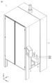
- FIG. 2 is a perspective view showing the appearance of the label attachment machine.
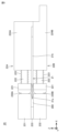
- FIG. 2 is a diagram for explaining a mechanism inside a housing.
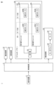
- FIG. 2 is a hardware block diagram of the label attachment machine.
- FIG. FIG. FIG. 13 is a diagram for explaining a label opener.
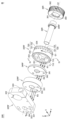
- FIG. 4 is an exploded view for explaining a part of the structure of the first suction unit.
- 11A and 11B are diagrams for explaining the arrangement of open ends of the suction roller. IX-IX line cross-sectional view of the suction roller.
- FIG. 13 is a diagram for explaining the positional relationship between a mandrel and a label opener.
- FIG. 1 is a perspective view showing the appearance of the label attachment machine.
- FIG. 2 is a diagram for explaining a mechanism inside a housing.
- FIG. 2 is a hardware block diagram of the label attachment machine.
- FIG. FIG. 13 is a diagram for explaining a label opener.
- FIG. 4 is an exploded view for explaining a part
- label attachment machine by taking as an example a label attachment machine that attaches heat-shrinkable labels (shrink labels) to the outer surface of containers.
- label attachment machine that attaches heat-shrinkable labels (shrink labels) to the outer surface of containers.
- shrink labels heat-shrinkable labels
- FIG. 1 is a perspective view showing the appearance of a label attachment machine 1 according to the present embodiment.
- the label attachment machine 1 includes a housing 2, an operation device 3, and a conveyor 4.
- the label attachment machine 1 covers the container 900 with the label 850 in the housing 2, and conveys the container 900 covered with the label 850 out of the housing 2 by the conveyor 4.
- the operation device 3 is The placement machine 1 accepts operations by an operator.
- the label will be referred to as "label 850" below regardless of the state of the label.
- FIG. 2 is a diagram for explaining the mechanism inside the housing 2.
- the label attachment machine 1 includes a conveying device 10, a cutting device 20, a label opener 30, a mandrel 40, a conveying device 50, belts 68R and 68L, and a pair of shot rollers (not shown).
- the conveying device 10 sends the tubular original roll 800, which has been folded flat, to the cutting device 20, which is located downstream of the conveying device 10.
- the cutting device 20 has a blade 21.
- the cutting device 20 cuts the tip side of the original roll 800 with the blade 21. This produces a label 850 of a predetermined length (a tubular label 850, which has been folded flat). Details of the cutting device 20 will be described later.
- the label opener 30 is located downstream of the cutting device 20.
- the label opener 30 has a first suction unit 30R and a second suction unit 30L that face each other.
- the label opener 30 spreads the flattened tubular label 850 while conveying it, thereby fitting the label 850 onto the mandrel 40. More specifically, the label opener 30 fits the label 850 onto the tip of the mandrel 40.
- the conveying device 50 has rollers 51R, 51L, 52R, 52L, 53R, and 53L, and belts 58R and 58L.
- Belts 58R and 58L are endless. Belt 58R is tensioned by rollers 51R, 52R, and 53R. Belt 58L is tensioned by rollers 51L, 52L, and 53L. In this example, rollers 51R and 51L are drive rollers. Rollers 51R and 51L rotate synchronously with each other. Rollers 52R, 52L, 53R, and 53L are driven rollers.
- the roller 51R rotates counterclockwise when viewed from the front of the label attachment machine 1 (viewed in the positive direction of the Y axis as in Figure 2). This causes the belt 58R to also rotate counterclockwise (in the direction of arrow P3).
- the roller 51L rotates clockwise when viewed from the front of the label attachment machine 1. This causes the belt 58L to also rotate clockwise (in the direction of arrow P4).
- roller 51R is configured to be movable in the direction of the mandrel 40 (the direction of arrow P1) in order to bring belt 58R into contact with the mandrel 40.
- the position of roller 52R also changes.
- the position of roller 53R does not change.
- roller 51L is configured to be movable in the direction of the mandrel 40 (the direction of arrow P2) in order to bring belt 58L into contact with the mandrel 40.
- the position of roller 52L also changes.
- the position of roller 53L does not change.
- the conveying device 50 conveys the tubular label 850 fitted onto the mandrel 40 downward (negative Z-axis direction) by sandwiching it between the mandrel 40 and the belts 58R and 58L with a portion of the belts 58R and 58L in contact with the mandrel 40.
- the pair of shot rollers receive the label 850 transferred downward by the conveying device 50 by pinching it between the mandrel 40 (more specifically, the lower part 42 of the mandrel 40), and send it downward while rotating in the circumferential direction.
- This allows the label attachment machine 1 to fit the label 850 onto the container 900 passing directly below the mandrel 40.
- the pair of shot rollers are disposed with their rotation axes inclined relative to the axis of the mandrel 40, and are driven by a motor (not shown).
- the belts 68R and 68L are for driving the label opener 30. Although details will be described later, the belt 68R drives and rotates a rotating body in the first suction unit 30R. The belt 68L rotates and drives a rotor in the second suction unit 30L.
- Belts 68R and 68L are endless.
- Belt 68R is tensioned by rollers 51R and 52R and driven roller 36R (FIG. 6), which is part of the rotating body and will be described later.
- Belt 68L is tensioned by rollers 51L and 52L and a roller (not shown), which is part of the rotating body and will be described later.
- Belt 68R rotates in the same direction as belt 58R in synchronization with belt 58R.
- belt 68L rotates in the same direction as belt 58L in synchronization with belt 58L.
- belt 68R overlaps with belt 58R in the section between roller 53R and roller 51R and in the section between roller 51R and roller 52R. Therefore, belt 68R is driven to rotate by frictional force with belt 58R in both sections.
- belt 68L overlaps with belt 58L in the section between roller 53L and roller 51L and in the section between roller 51L and roller 52L. Therefore, belt 68L is driven to rotate by frictional force with belt 58L in both sections.
- FIG. 3 is a hardware block diagram of the label attachment machine 1. As shown in FIG. 3, the label attachment machine 1 further includes a control device 5 in addition to an operating device 3, a conveying device 10, a cutting device 20, a label opener 30, and a conveying device 50.
- a control device 5 in addition to an operating device 3, a conveying device 10, a cutting device 20, a label opener 30, and a conveying device 50.
- the control device 5 acquires the information input using the operation device 3.
- the control device 5 controls the operation of the label attachment machine 1 based on the information.
- the conveying device 50 includes a motor driver 54 and a motor 55.
- the motor driver 54 rotates the motor 55 in response to a command from the control device 5.
- the rotation of the motor 55 rotates the rollers 51R and 51L.
- the label opener 30 further includes a suction machine 39 in addition to the first suction unit 30R and the second suction unit 30L.
- the suction machine 39 operates in response to a command from the control device 5. When the suction machine 39 is driven, air is sucked from the first suction unit 30R and the second suction unit 30L through the piping.
- the suction machine 39 is, for example, a vacuum pump.
- the first suction unit 30R is equipped with a suction roller 35RF and a suction roller 35RB, which have the same rotation axis.
- the second suction unit 30L is equipped with a suction roller 35LF and a suction roller 35LB, which have the same rotation axis.
- the suction roller 35RF of the first suction unit 30R and the suction roller 35LF of the second suction unit 30L face each other and form a roller pair 391.
- the suction roller 35RB of the first suction unit 30R and the suction roller 35LB of the second suction unit 30L face each other and form a roller pair 392. Details of the first suction unit 30R and the second suction unit 30L will be described later.
- Fig. 4 is a top view of the cutting device 20 shown in Fig. 2. As shown in Fig. 4, the cutting device 20 includes a blade 21, a movable member 22A, and a fixed member 231.
- the movable member 22A includes a pressing portion 221, a support rod 222, a spring 223, and a base 224A.
- One end of the support rod 222 is housed within the base 224A.
- the other end of the support rod 222 is connected to the pressing portion 221.
- One end of the spring 223 is fixed to the base 224A.
- the other end of the spring 223 is connected to the pressing portion 221.
- the movable member 22A can move in the direction of the arrow W1 (negative direction of the X-axis). Specifically, when the base 224A moves due to an external force, the pressing portion 221, the support rod 222, and the spring 223 move in the direction of the arrow W1.
- the blade 21 has a cutting edge 21a and a belly 21b. A portion of the belly 21b is fixed to the base 224A. The above-mentioned movement of the base 224A also causes the blade 21 to move in the direction of the arrow W1.
- the fixed member 231 has a wall surface 239A that faces the original roll 800.
- a gap 290 is generated between the wall surface 239A and the pressing portion 221.
- the original roll 800 is fed into the gap 290 from above.
- the blade length direction of the blade 21 is inclined at a predetermined angle with respect to the arrangement direction of the wall surface 239A when viewed from above the cutting device 20.
- FIG. 5 is a side view of the cutting device 20.
- FIG. 5 shows the state after the blade 21 has been moved in the direction of the arrow W1 in FIG. 4.
- the cutting device 20 in addition to the blade 21, the movable member 22A, and the fixed member 231, the cutting device 20 further includes a movable member 22B, a fixed member 232, and a spacer 233.
- movable member 22B Like movable member 22A, movable member 22B includes a pressing portion 221, a support rod 222, and a spring 223. Instead of base 224A, movable member 22B includes base 224B, which has a different shape from base 224A. Base 224A is fixed onto base 224B. Blade 21 is fixed to base 224A and base 224B with belly 21b sandwiched between base 224A and base 224B.
- the fixing member 232 has a wall surface 239B that faces the original roll 800.
- the wall surface 239B is located downstream of the wall surface 239A in the conveying direction of the original roll 800.
- the wall surfaces 239A and 239B are included in the same imaginary plane.
- a spacer 233 is disposed between the fixing members 231 and 232.
- the spacer 233 forms a space 280 between the fixing members 231 and 232.
- the raw roll 800 is intermittently (periodically) sent to the cutting device 20 by a servo motor or the like. At the moment that the movement of the raw roll 800 stops, the raw roll 800 is pressed against the wall surfaces 239A and 239B by the two pressing parts 221, and is then cut by the blade 21. After cutting, the raw roll 800 is again supplied to the cutting device 20 by the conveying device 10.
- the pressing portion 221 of the movable member 22A periodically presses the original web 800 against the wall surface 239A.
- the pressing portion 221 of the movable member 22B presses the original web 800 against the wall surface 239A in synchronization with the pressing portion 221 of the movable member 22A.
- the cutting device 20 moves the blade tip 21a to the inside of the space 280 with the same period as the period in which the original web 800 is pressed against the wall surfaces 239A and 239B.
- Fig. 6 is a diagram for explaining the label opener 30 shown in Fig. 2.
- the label opener 30 includes a first suction unit 30R and a second suction unit 30L.
- the first suction unit 30R and the second suction unit 30L are configured symmetrically with respect to the label 850.
- the first suction unit 30R includes pipes 31RF, 31RB, base members 32RF, 32RB, first ring members 33RF, 33RB, second ring members 34RF, 34RB, suction rollers 35RF, 35RB, driven roller 36R, and support member 37R. Note that pipe 31RB is not shown in FIG. 6. Pipe 31RB is attached to base member 32RB.
- the suction rollers 35RF and 35RB are disposed so as to sandwich the driven roller 36R from both ends.
- the suction rollers 35RF and 35RB are fixed to the driven roller 36R with bolts.
- the support member 37R is attached to the base members 32RF and 32RB, and supports the base members 32RF and 32RB.
- the first suction unit 30R has a symmetrical configuration with respect to the driven roller 36R.
- the suction rollers 35RF, 35RB and driven roller 36R of the first suction unit 30R rotate in the direction of the arrow Q1 as the belt 68R is driven in the direction of the arrow P5. More specifically, the suction rollers 35RF, 35RB are connected to the driven roller 36R and therefore rotate in accordance with the rotation of the driven roller 36R. Note that the base members 32RF, 32RB, the first ring members 33RF, 33RB, and the second ring members 34RF, 34RB do not rotate.
- the suction rollers 35RF and 35RB have multiple flow paths that connect the end faces to the outer circumferential surface. As shown in FIG. 6, the outer circumferential surface has multiple openings for sucking outside air into the inside (flow paths).
- the second suction unit 30L includes pipes 31LF, 31LB, base members 32LF, 32LB, first ring members 33LF, 33LB, second ring members 34LF, 34LB, suction rollers 35LF, 35LB, driven roller 36L, and support member 37L. Note that in FIG. 6, pipe 31LB, base member 32LB, first ring member 33LB, second ring member 34LB, and suction roller 35LB are not shown. Pipe 31LB is attached to base member 32LB.
- the suction rollers 35LF and 35LB are disposed so as to sandwich the driven roller 36L from both ends.
- the suction rollers 35LF and 35LB are fixed to the driven roller 36L with bolts.
- the support member 37L is attached to the base members 32LF and 32LB, and supports the base members 32LF and 32LB.
- the second suction unit 30L has a configuration symmetrical with respect to the driven roller 36L.
- the suction rollers 35LF, 35LB and driven roller 36L of the second suction unit 30L rotate in the direction of arrow Q2 (opposite the direction of arrow Q1) as the belt 68L is driven in the direction of arrow P6. More specifically, the suction rollers 35LF, 35LB are connected to the driven roller 36L and therefore rotate in accordance with the rotation of the driven roller 36L. Note that the base members 32LF, 32LB, the first ring members 33LF, 33LB, and the second ring members 34LF, 34LB do not rotate.
- Suction rollers 35LF, 35LB like suction rollers 35RF, 35RB, have multiple flow paths formed from the end faces to the outer circumferential surface. Multiple openings are formed on the outer circumferential surface to draw outside air into the interior (flow paths).
- the suction roller 35RF faces the suction roller 35LF
- the suction roller 35RB faces the suction roller 35LB.
- the label opener 30 holds the label 850 between the suction rollers 35RF, 35RB and the suction rollers 35LF, 35LB, and transports the label 850 by rotating the suction rollers 35RF, 35RB and the suction rollers 35LF, 35LB.
- the label opener 30 spreads the label 850 in the positive direction of the Y axis using suction rollers 35RF and 35RB, and spreads the label 850 in the negative direction of the Y axis using suction rollers 35LF and 35LB.
- the suction machine 39 ( Figure 3) sucks air from the suction roller 35RF via the pipe 31RF. Similarly, the suction machine 39 sucks air from the suction roller 35RB via the pipe 31RB (not shown). The suction machine 39 sucks air from the suction roller 35LF via the pipe 31LF. The suction machine 39 sucks air from the suction roller 35LB (not shown) via the pipe 31LB (not shown).
- the first suction unit 30R and the second suction unit 30L have the same functions, except that the rotation directions of the suction rollers 35RF, 35RB and driven roller 36R are different from those of the suction rollers 35LF, 35LB and driven roller 36L. Therefore, the following description will focus on the first suction unit 30R.
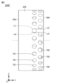
- FIG. 7 is an exploded view illustrating part of the structure of the first suction unit 30R. As shown in FIG. 7, the first suction unit 30R further includes a shaft 38R and a bearing 39RF.
- a base member 32RF, a first ring member 33RF, a second ring member 34RF, a suction roller 35RF, and a driven roller 36R are arranged in this order.
- the base member 32RF has through holes 321 to 324 formed in the Y-axis direction.
- the first ring member 33RF has through holes 331 and 333 formed in the Y-axis direction.
- the second ring member 34RF has through holes 341 and 343 formed in the Y-axis direction.
- the suction roller 35RF has a through hole 351 formed in the Y-axis direction.
- the suction roller 35RF has a groove portion 359 (see Figure 9) into which the bearing 39RF is inserted.
- the driven roller 36R has a through hole 361 formed in the Y-axis direction.
- the driven roller 36R has a groove 369 into which the bearing 39RF is inserted.
- the outer peripheral surface 362 of the driven roller 36R has a continuous uneven shape to increase friction with the belt 68R ( Figure 6).
- Shaft 38R is inserted into through holes 321, 331, 341, 351, and 361.
- An end of support member 37R ( Figure 6) is inserted into through hole 322.
- a bolt is inserted into through hole 324 and tightened. This fixes support member 37R to base member 32RF.
- the base member 32RF and the first ring member 33RF are in close contact with each other.
- the first ring member 33RF and the second ring member 34RF are in close contact with each other.
- the second ring member 34RF and the suction roller 35RF are spaced apart by about 1 mm.
- the second ring member 34RF is made of a metal that is softer than the suction roller 35RF because there is a risk that it may come into contact with the rotating suction roller 35RF.
- the second ring member 34RF is made of gunmetal.
- Arrows R1 to R4 indicate the air flow when the suction device 39 is operated. Air is sucked in from the suction roller 35RF and passes through the through holes 343, 333, and 323 in that order before being sent to the pipe 31RF ( Figure 6).
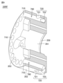
- FIG. 8 is a diagram for explaining the arrangement of the opening ends of the suction roller 35RF.
- FIG. 9 is a cross-sectional view of the suction roller 35RF shown in FIG. 7 taken along line IX-IX. The following describes the details of the suction roller 35RF with reference to FIGS. 7 to 9.
- the suction roller 35RF has an outer peripheral surface 352 and end surfaces 353, 354. As shown in FIG. 9, the suction roller 35RF has a plurality of flow paths 790 formed therein, which connect the end surface 353 to the outer peripheral surface 352.
- Each flow path 790 has an opening end (first opening end) 720 on the outer peripheral surface 352 side, and an opening end (second opening end) 710 on the end surface 353 side.
- each opening end 720 is composed of two opening ends 721, 722.
- the opening shapes of the opening ends 710, 721, 722 are circular.
- each opening end 720 is located near the driven roller 36R. Therefore, the suction roller 35RF can spread the labels, from narrow to wide.
- a plurality of opening ends 721 are formed in a line in the circumferential direction on the outer peripheral surface 352.
- a plurality of opening ends 722 are formed in a line in the circumferential direction on the outer peripheral surface 352.
- the plurality of opening ends 721 form a first row (first row)
- the plurality of opening ends 722 form a second row (second row).
- imaginary straight lines L1 to L4 in FIG. 8 when viewed from the end face 353 side, a portion of the opening end 721 of the first row overlaps a portion of the opening end 722 of the second row.
- imaginary straight lines L1 to L4 are straight lines parallel to the Y axis. Specifically, when viewed from the end face 353 side, the opening ends overlap between imaginary straight lines L1 and L2, and the opening ends overlap between imaginary straight lines L3 and L4.
- the suction device 39 sucks air from the opening end 710 of the flow path 790 that has at least the opening end 720 facing the label 850 among the multiple opening ends 710.
- the suction device 39 sucks air from the multiple opening ends 710 (three in this example) surrounded by the dashed line U through the through holes 323, 333, and 343.
- This suction process allows the flattened cylindrical label 850 to be expanded in the positive direction of the Y axis. More specifically, the middle of one side of the label 850 (the side in contact with the suction roller 35RF) is moved in the positive direction of the Y axis.
- the suction roller 35RB ( Figure 6) can also spread the flattened tubular label 850 in the positive direction of the Y axis. Furthermore, the suction rollers 35LF, LB of the second suction unit 30L can spread the flattened tubular label 850 in the negative direction of the Y axis.
- the four suction rollers 35RF, RB, 35LF, and LB make it possible to spread the flattened cylindrical label 850 on both sides (the positive Y-axis direction and the negative Y-axis direction). Therefore, the label opener 30 can fit the label 850 onto the mandrel 40.
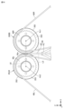
- Figure 10 is a diagram for explaining the positional relationship between the mandrel 40 and the label opener 30.
- the mandrel 40 has a main body 41 including a lower portion 42 (see Figure 2), and a blade 43 attached to the upper side of the main body 41.
- the mandrel 40 has a lower end 42a (see Figure 2) on the container 900 side, and a tip 43a on the opposite side to the lower end 42a.
- the tip 43a is the upper end of the blade 43.
- the position of the tip portion 43 a is lower than the rotation axis Ax 1 of the suction rollers 35 RF and 35 RB and the rotation axis Ax 2 of the suction rollers 35 LF and 35 LB, and is higher than the lower end of the end surface 353 .
- the position of the tip 43a is lower than the imaginary line L6 connecting the rotation axis Ax1 and the rotation axis Ax2, and higher than the imaginary line L5 connecting the lower end of the suction roller 35RB and the lower end of the suction roller 35LB.
- Blade 43 is a plate-like member having a main surface parallel to the YZ plane. The thickness direction of blade 43 is in the X-axis direction. Tip 43a of blade 43 is close to outer circumferential surfaces 352 of suction rollers 35RF and 35RB and outer circumferential surfaces 352 of suction rollers 35LF and 35LB.
- the label attachment machine 1 includes a label opener 30 that conveys and spreads a tubular label 850 that has been folded flat, and a conveying device 50 that conveys the label 850 spread by the label opener 30 so that it can be attached to a container 900.
- the label opener 30 includes suction rollers 35RF (35RB) and suction rollers 35LF (35LB) that face each other and each have an outer peripheral surface 352 and an end surface 353.
- the label opener 30 conveys the label 850 by rotating the suction rollers 35RF (35RB) and suction rollers 35LF (35LB) while clamping the label 850 between the suction rollers 35RF (35RB) and suction rollers 35LF (35LB).
- the suction roller 35RF (35RB) and the suction roller 35LF (35LB) have a plurality of flow paths 790 formed therein, which connect the end surface 353 to the outer peripheral surface 352.
- Each flow path 790 has an opening end 720 on the outer peripheral surface 352 side and an opening end 710 on the end surface 353 side.
- multiple opening ends 720 are formed in a line in the circumferential direction on the outer peripheral surface 352. As shown in Figures 7 and 9, multiple opening ends 710 are formed in a line on the end surface 353.
- the label opener 30 further includes a suction device 39 that sucks air from the opening end 710 of a flow path 790 having an opening end 720 facing the label 850, at least among the multiple opening ends 710 (inside the flow path 790 having the opening end 720 facing the label 850).
- the suction roller 35RF (35RB) and the suction roller 35LF (35LB) can suck the side (surface) of the label 850 toward the opening end 720 of the flow path 790. Furthermore, since the suction roller 35RF (35RB) and the suction roller 35LF (35LB) continue to rotate while the label 850 is being sucked in, the end of the label 850 on the mandrel 40 side opens. In addition, since the suction roller 35RF (35RB) and the suction roller 35LF (35LB) are configured to abut against the label 850, the original roll 800 that is folded flat can be spread without using a member such as a belt with a through hole. Therefore, the label attachment machine 1 can efficiently spread a tubular label that is folded flat.
- the label 850 can be spread regardless of the width (length in the Y-axis direction) of the label 850. Also, since there is no need to install an inner guide inside the original roll 800, there is no need to take the trouble of replacing the inner guide depending on the width of the original roll 800.
- a plurality of opening ends 720 (721, 722) are formed on the outer peripheral surface 352 so as to form a first row and a second row in the circumferential direction.
- a portion of the opening end 721 of the first row overlaps with a portion of the opening end 722 of the second row.
- At least one opening end 720 faces the label 850 regardless of the rotational position of the suction roller 35RF (35RB, 35LF, 35LB). Therefore, compared to a configuration in which a portion of the opening end 721 of the first row does not overlap a portion of the opening end 722 of the second row, and a configuration that has only the first row, the flattened tubular label 850 can be unfolded more reliably.
- the label attachment machine 1 includes a mandrel 40.
- the label opener 30 fits the label 850 onto the mandrel 40.
- the mandrel 40 has a lower end 42a on the container 900 side and a tip end 43a on the opposite side to the lower end 42a.
- the position of the tip end 43a is lower than the rotation axis Ax1 of the suction roller 35RF (35RB) and the rotation axis Ax2 of the suction roller 35LF (35LB), and higher than the lower end of the end face 353.
- the label attachment machine 1 further includes endless belts 58R, 68R, 58L, and 68L, each of which is tensioned, and a motor 55 (FIG. 3) that simultaneously rotates the belts 58R, 68R, 58L, and 68L.
- the conveying device 50 includes belts 58R and 58L, and conveys the label 850 fitted onto the mandrel 40 by the rotation of the belts 58R and 58L.
- the suction rollers 35RF (35RB) and suction rollers 35LF (35LB) rotate by the rotation of the belts 68R and 68L, respectively.
- a single motor 55 can drive the conveying device 50, the suction roller 35RF (35RB), and the suction roller 35LF (35LB).
- the label attachment machine 1 further includes a cutting device 20 having a blade tip 21a and cutting the flattened original web 800 to a predetermined length with the blade tip 21a to produce labels 850 to be supplied to the label opener 30.
- the cutting device 20 includes wall surface 239A and wall surface 239B, each of which faces the original web 800. Wall surface 239B is located downstream of wall surface 239A in the conveying direction of the original web 800. A space 280 capable of accommodating the blade tip 21a is formed between wall surface 239A and wall surface 239B.
- Cutting device 20 further includes an upper pressing section 221 that periodically presses raw roll 800 against wall surface 239A, and a lower pressing section 221 that presses raw roll 800 against wall surface 239B in synchronization with upper pressing section 221. Cutting device 20 moves cutting edge 21a into space 280 with the same period as the period in which raw roll 800 is pressed against wall surfaces 239A and 239B.
- This configuration allows the original roll 800 to be cut in mid-air. This makes it possible to prevent the cut surfaces of the original roll 800 from welding together. This makes it possible to open up the label 850 using the label opener 30.
- first suction unit 30R and the second suction unit 30L each have two suction rollers, but the present invention is not limited to this.
- Each of the first suction unit 30R and the second suction unit 30L may have one suction roller.
- each of the first suction unit 30R and the second suction unit 30L may have three or more suction rollers.
- the suction roller is described as having two rows of multiple opening ends 720 in the circumferential direction, but this is not necessarily limited to this.
- the multiple opening ends 720 may be arranged in one row or three rows in the circumferential direction.
- a cylindrical raw roll 800 folded flat is carried into the housing 2 in a state of being wound in a concentric shape around a core, that is, as a roll product.
- This roll product is long, and a plurality of raw rolls 800 are joined together to form a single long body to obtain a desired length.
- the portion where the raw rolls are joined together is called a seam.
- the cylindrical raw roll 800 including the seam is cut by the cutting device 20 to generate a label 850 of a predetermined length, and therefore the label 850 including the seam is also generated.
- one motor 55 rotates endless belts 58R, 68R, 58L, and 68L, and suction roller 35RF (35RB) and suction roller 35LF (35LB) rotate by the rotation of belts 68R and 68L, respectively.
- suction roller 35RF (35RB) and suction roller 35LF (35LB) rotate by the rotation of belts 68R and 68L, respectively.
- a sensor for detecting the seam of the label 850 may be provided.
- the sensor is installed upstream of the label opener 30.
- the control device 5 controls the first suction unit 30R and the second suction unit 30L to stop the suction of either the suction roller 35RF (35RB) or the suction roller 35LF (35LB). For example, suppose that the suction roller 35LF (35LB) is stopped. Then, only the suction roller 35RF (35RB) will suck the label 850, and the folded label 850 will rotate together with the suction roller 35RF (35RB) while being sucked by it. Then, by stopping the suction at a position away from the mandrel 40, i.e., at a position where there is no interference, the suction state is released and the label 850 having the seam can be rejected.
- 1 Label attachment machine 2 Housing, 3 Operating device, 4 Conveyor, 5 Control device, 10, 50 Conveying device, 20 Cutting device, 21 Blade, 21a Blade tip, 21b Belly, 22A, 22B Movable member, 30 Label opener, 30L Second suction unit, 30R First suction unit, 31LF, 31RB, 31RF Pipe, 32RB, 32RF Base member, 33RB, 33RF First ring member, 34RB, 34RF Second ring member, 35RB, 35RF, 35LB, 35LF Suction roller, 36L, 36R Driven roller, 37L, 37R Support member, 38R Shaft, 39 Suction machine, 39RF Bearing, 40 Mandrel, 41 Main body, 42 Lower portion, 42a Lower end portion, 43 Blade, 43a Tip portion, 51L, 51R, 52L, 52R, 53L, 53R Roller, 54 Motor driver, 55 Motor, 58L, 58R, 68L, 68R Belt, 221 Pressing portion, 222 Support rod, 223 Spring, 224A, 224B Base portion,
Landscapes
- Engineering & Computer Science (AREA)
- Mechanical Engineering (AREA)
- Labeling Devices (AREA)
Priority Applications (1)
| Application Number | Priority Date | Filing Date | Title |
|---|---|---|---|
| JP2024555785A JPWO2024075673A1 (enExample) | 2022-10-07 | 2023-10-02 |
Applications Claiming Priority (2)
| Application Number | Priority Date | Filing Date | Title |
|---|---|---|---|
| JP2022-162089 | 2022-10-07 | ||
| JP2022162089 | 2022-10-07 |
Publications (1)
| Publication Number | Publication Date |
|---|---|
| WO2024075673A1 true WO2024075673A1 (ja) | 2024-04-11 |
Family
ID=90608085
Family Applications (1)
| Application Number | Title | Priority Date | Filing Date |
|---|---|---|---|
| PCT/JP2023/035848 Ceased WO2024075673A1 (ja) | 2022-10-07 | 2023-10-02 | ラベル装着機 |
Country Status (2)
| Country | Link |
|---|---|
| JP (1) | JPWO2024075673A1 (enExample) |
| WO (1) | WO2024075673A1 (enExample) |
Citations (5)
| Publication number | Priority date | Publication date | Assignee | Title |
|---|---|---|---|---|
| US4016704A (en) * | 1975-07-02 | 1977-04-12 | Masaaki Fujio | Method and apparatus for encapsulating container with tubular wrapping member |
| US4481064A (en) * | 1982-12-15 | 1984-11-06 | Westlund Gerald D | Dual rotary head banding machine |
| JPH01139321A (ja) * | 1987-11-20 | 1989-05-31 | Fuji Seal Kogyo Kk | 容器等へのチューブ嵌装方法とその装置 |
| FR2671779A1 (fr) * | 1991-01-17 | 1992-07-24 | Vallageas Alain | Dispositif pour la pose a grande cadence de manchons tubulaires sur des objets. |
| JP2020164246A (ja) * | 2019-03-29 | 2020-10-08 | 株式会社ダイワハイテックス | 包装装置 |
-
2023
- 2023-10-02 JP JP2024555785A patent/JPWO2024075673A1/ja active Pending
- 2023-10-02 WO PCT/JP2023/035848 patent/WO2024075673A1/ja not_active Ceased
Patent Citations (5)
| Publication number | Priority date | Publication date | Assignee | Title |
|---|---|---|---|---|
| US4016704A (en) * | 1975-07-02 | 1977-04-12 | Masaaki Fujio | Method and apparatus for encapsulating container with tubular wrapping member |
| US4481064A (en) * | 1982-12-15 | 1984-11-06 | Westlund Gerald D | Dual rotary head banding machine |
| JPH01139321A (ja) * | 1987-11-20 | 1989-05-31 | Fuji Seal Kogyo Kk | 容器等へのチューブ嵌装方法とその装置 |
| FR2671779A1 (fr) * | 1991-01-17 | 1992-07-24 | Vallageas Alain | Dispositif pour la pose a grande cadence de manchons tubulaires sur des objets. |
| JP2020164246A (ja) * | 2019-03-29 | 2020-10-08 | 株式会社ダイワハイテックス | 包装装置 |
Also Published As
| Publication number | Publication date |
|---|---|
| JPWO2024075673A1 (enExample) | 2024-04-11 |
Similar Documents
| Publication | Publication Date | Title |
|---|---|---|
| JP5167371B2 (ja) | おむつ/おしめブランクの折り畳み装置及び折り畳み方法 | |
| EP2135591B1 (en) | Machining apparatus | |
| US3939031A (en) | Device for butt splicing webs | |
| EP0159627A2 (en) | Revolving transfer roll | |
| CN111003277B (zh) | 制袋包装机 | |
| CN111003275B (zh) | 制袋包装机 | |
| CN111003276B (zh) | 制袋包装机 | |
| CN109153215B (zh) | 用于生产瓦楞板的系统 | |
| JP4937905B2 (ja) | 平らな物体を包装する方法および装置 | |
| GB2135283A (en) | Splicing webs | |
| WO2024075673A1 (ja) | ラベル装着機 | |
| US7776172B2 (en) | Web joining apparatus and method | |
| EP0842882B1 (en) | Method and apparatus for splicing web | |
| JP3046790B2 (ja) | コーティング基材の乾燥装置および乾燥方法 | |
| JP2003252495A (ja) | 紙接続装置及び紙接続方法 | |
| JP5556470B2 (ja) | シート状物接合装置、シート状物接合方法、および電池箔の接合方法 | |
| JP3517288B2 (ja) | 送りローラおよび給紙装置 | |
| JP5791473B2 (ja) | 粘着シートロールの包装方法およびその装置 | |
| EP0425656B1 (en) | Apparatus for forming endless loops from sheet material | |
| KR101631832B1 (ko) | 박스 제작용 합지 검사장치 | |
| JPH0569390A (ja) | 回転ドラム式切断装置 | |
| CN212581105U (zh) | 一种铝箔纸输送装置 | |
| JP3096769B2 (ja) | ロール状物品の胴巻き包装装置 | |
| JPH0478543B2 (enExample) | ||
| JP7171428B2 (ja) | 吸収性物品に係る連続シートの複合体を製造する方法、及び、製造装置 |
Legal Events
| Date | Code | Title | Description |
|---|---|---|---|
| 121 | Ep: the epo has been informed by wipo that ep was designated in this application |
Ref document number: 23874800 Country of ref document: EP Kind code of ref document: A1 |
|
| WWE | Wipo information: entry into national phase |
Ref document number: 2024555785 Country of ref document: JP |
|
| NENP | Non-entry into the national phase |
Ref country code: DE |
|
| 122 | Ep: pct application non-entry in european phase |
Ref document number: 23874800 Country of ref document: EP Kind code of ref document: A1 |