WO2024075477A1 - 避難情報生成システム、避難情報生成装置、自律走行装置、避難情報生成方法、避難情報生成プログラム - Google Patents
避難情報生成システム、避難情報生成装置、自律走行装置、避難情報生成方法、避難情報生成プログラム Download PDFInfo
- Publication number
- WO2024075477A1 WO2024075477A1 PCT/JP2023/033208 JP2023033208W WO2024075477A1 WO 2024075477 A1 WO2024075477 A1 WO 2024075477A1 JP 2023033208 W JP2023033208 W JP 2023033208W WO 2024075477 A1 WO2024075477 A1 WO 2024075477A1
- Authority
- WO
- WIPO (PCT)
- Prior art keywords
- information
- evacuation
- hazard
- evacuation information
- travel area
- Prior art date
- Legal status (The legal status is an assumption and is not a legal conclusion. Google has not performed a legal analysis and makes no representation as to the accuracy of the status listed.)
- Ceased
Links
Images




Classifications
-
- G—PHYSICS
- G05—CONTROLLING; REGULATING
- G05D—SYSTEMS FOR CONTROLLING OR REGULATING NON-ELECTRIC VARIABLES
- G05D1/00—Control of position, course, altitude or attitude of land, water, air or space vehicles, e.g. using automatic pilots
- G05D1/20—Control system inputs
- G05D1/24—Arrangements for determining position or orientation
- G05D1/246—Arrangements for determining position or orientation using environment maps, e.g. simultaneous localisation and mapping [SLAM]
-
- G—PHYSICS
- G05—CONTROLLING; REGULATING
- G05D—SYSTEMS FOR CONTROLLING OR REGULATING NON-ELECTRIC VARIABLES
- G05D1/00—Control of position, course, altitude or attitude of land, water, air or space vehicles, e.g. using automatic pilots
- G05D1/60—Intended control result
- G05D1/617—Safety or protection, e.g. defining protection zones around obstacles or avoiding hazards
-
- G—PHYSICS
- G05—CONTROLLING; REGULATING
- G05D—SYSTEMS FOR CONTROLLING OR REGULATING NON-ELECTRIC VARIABLES
- G05D1/00—Control of position, course, altitude or attitude of land, water, air or space vehicles, e.g. using automatic pilots
- G05D1/60—Intended control result
- G05D1/69—Coordinated control of the position or course of two or more vehicles
-
- G—PHYSICS
- G05—CONTROLLING; REGULATING
- G05D—SYSTEMS FOR CONTROLLING OR REGULATING NON-ELECTRIC VARIABLES
- G05D1/00—Control of position, course, altitude or attitude of land, water, air or space vehicles, e.g. using automatic pilots
- G05D1/60—Intended control result
- G05D1/69—Coordinated control of the position or course of two or more vehicles
- G05D1/698—Control allocation
- G05D1/6987—Control allocation by centralised control off-board any of the vehicles
-
- G—PHYSICS
- G06—COMPUTING OR CALCULATING; COUNTING
- G06Q—INFORMATION AND COMMUNICATION TECHNOLOGY [ICT] SPECIALLY ADAPTED FOR ADMINISTRATIVE, COMMERCIAL, FINANCIAL, MANAGERIAL OR SUPERVISORY PURPOSES; SYSTEMS OR METHODS SPECIALLY ADAPTED FOR ADMINISTRATIVE, COMMERCIAL, FINANCIAL, MANAGERIAL OR SUPERVISORY PURPOSES, NOT OTHERWISE PROVIDED FOR
- G06Q90/00—Systems or methods specially adapted for administrative, commercial, financial, managerial or supervisory purposes, not involving significant data processing
-
- G—PHYSICS
- G08—SIGNALLING
- G08B—SIGNALLING SYSTEMS, e.g. PERSONAL CALLING SYSTEMS; ORDER TELEGRAPHS; ALARM SYSTEMS
- G08B27/00—Alarm systems in which the alarm condition is signalled from a central station to a plurality of substations
-
- G—PHYSICS
- G08—SIGNALLING
- G08B—SIGNALLING SYSTEMS, e.g. PERSONAL CALLING SYSTEMS; ORDER TELEGRAPHS; ALARM SYSTEMS
- G08B7/00—Signalling systems according to two or more of groups G08B3/00 - G08B6/00
- G08B7/06—Signalling systems according to two or more of groups G08B3/00 - G08B6/00 using electric transmission, e.g. involving audible and visible signalling through the use of sound and light sources
- G08B7/066—Signalling systems according to two or more of groups G08B3/00 - G08B6/00 using electric transmission, e.g. involving audible and visible signalling through the use of sound and light sources guiding along a path, e.g. evacuation path lighting strip
-
- G—PHYSICS
- G08—SIGNALLING
- G08G—TRAFFIC CONTROL SYSTEMS
- G08G1/00—Traffic control systems for road vehicles
-
- G—PHYSICS
- G08—SIGNALLING
- G08G—TRAFFIC CONTROL SYSTEMS
- G08G1/00—Traffic control systems for road vehicles
- G08G1/09—Arrangements for giving variable traffic instructions
-
- G—PHYSICS
- G08—SIGNALLING
- G08G—TRAFFIC CONTROL SYSTEMS
- G08G1/00—Traffic control systems for road vehicles
- G08G1/123—Traffic control systems for road vehicles indicating the position of vehicles, e.g. scheduled vehicles; Managing passenger vehicles circulating according to a fixed timetable, e.g. buses, trains, trams
- G08G1/127—Traffic control systems for road vehicles indicating the position of vehicles, e.g. scheduled vehicles; Managing passenger vehicles circulating according to a fixed timetable, e.g. buses, trains, trams to a central station ; Indicators in a central station
- G08G1/13—Traffic control systems for road vehicles indicating the position of vehicles, e.g. scheduled vehicles; Managing passenger vehicles circulating according to a fixed timetable, e.g. buses, trains, trams to a central station ; Indicators in a central station the indicator being in the form of a map
-
- G—PHYSICS
- G16—INFORMATION AND COMMUNICATION TECHNOLOGY [ICT] SPECIALLY ADAPTED FOR SPECIFIC APPLICATION FIELDS
- G16Y—INFORMATION AND COMMUNICATION TECHNOLOGY SPECIALLY ADAPTED FOR THE INTERNET OF THINGS [IoT]
- G16Y10/00—Economic sectors
- G16Y10/40—Transportation
-
- G—PHYSICS
- G16—INFORMATION AND COMMUNICATION TECHNOLOGY [ICT] SPECIALLY ADAPTED FOR SPECIFIC APPLICATION FIELDS
- G16Y—INFORMATION AND COMMUNICATION TECHNOLOGY SPECIALLY ADAPTED FOR THE INTERNET OF THINGS [IoT]
- G16Y20/00—Information sensed or collected by the things
- G16Y20/10—Information sensed or collected by the things relating to the environment, e.g. temperature; relating to location
-
- G—PHYSICS
- G16—INFORMATION AND COMMUNICATION TECHNOLOGY [ICT] SPECIALLY ADAPTED FOR SPECIFIC APPLICATION FIELDS
- G16Y—INFORMATION AND COMMUNICATION TECHNOLOGY SPECIALLY ADAPTED FOR THE INTERNET OF THINGS [IoT]
- G16Y30/00—IoT infrastructure
-
- G—PHYSICS
- G16—INFORMATION AND COMMUNICATION TECHNOLOGY [ICT] SPECIALLY ADAPTED FOR SPECIFIC APPLICATION FIELDS
- G16Y—INFORMATION AND COMMUNICATION TECHNOLOGY SPECIALLY ADAPTED FOR THE INTERNET OF THINGS [IoT]
- G16Y40/00—IoT characterised by the purpose of the information processing
- G16Y40/20—Analytics; Diagnosis
-
- G—PHYSICS
- G05—CONTROLLING; REGULATING
- G05D—SYSTEMS FOR CONTROLLING OR REGULATING NON-ELECTRIC VARIABLES
- G05D2105/00—Specific applications of the controlled vehicles
- G05D2105/55—Specific applications of the controlled vehicles for emergency activities, e.g. search and rescue, traffic accidents or fire fighting
-
- G—PHYSICS
- G05—CONTROLLING; REGULATING
- G05D—SYSTEMS FOR CONTROLLING OR REGULATING NON-ELECTRIC VARIABLES
- G05D2105/00—Specific applications of the controlled vehicles
- G05D2105/70—Specific applications of the controlled vehicles for displaying or announcing information
-
- G—PHYSICS
- G05—CONTROLLING; REGULATING
- G05D—SYSTEMS FOR CONTROLLING OR REGULATING NON-ELECTRIC VARIABLES
- G05D2105/00—Specific applications of the controlled vehicles
- G05D2105/80—Specific applications of the controlled vehicles for information gathering, e.g. for academic research
- G05D2105/87—Specific applications of the controlled vehicles for information gathering, e.g. for academic research for exploration, e.g. mapping of an area
-
- G—PHYSICS
- G05—CONTROLLING; REGULATING
- G05D—SYSTEMS FOR CONTROLLING OR REGULATING NON-ELECTRIC VARIABLES
- G05D2107/00—Specific environments of the controlled vehicles
- G05D2107/60—Open buildings, e.g. offices, hospitals, shopping areas or universities
-
- G—PHYSICS
- G05—CONTROLLING; REGULATING
- G05D—SYSTEMS FOR CONTROLLING OR REGULATING NON-ELECTRIC VARIABLES
- G05D2109/00—Types of controlled vehicles
- G05D2109/10—Land vehicles
-
- G—PHYSICS
- G05—CONTROLLING; REGULATING
- G05D—SYSTEMS FOR CONTROLLING OR REGULATING NON-ELECTRIC VARIABLES
- G05D2111/00—Details of signals used for control of position, course, altitude or attitude of land, water, air or space vehicles
- G05D2111/30—Radio signals
Definitions
- This disclosure relates to technology for generating evacuation information in the driving area of an autonomous driving device.
- Patent Document 1 discloses a system that guides a person being guided from inside a building to the outside when an event occurs. When an event occurs, this system sets up an evacuation route from the current location of the person being guided to the building exit.
- evacuation routes are set based on the current location of the person being guided and the location of the building's exit, without taking into consideration whether the route is actually passable. Therefore, there is a risk that an effective evacuation route cannot be set, as the route may become impassable due to a hazard such as a disaster.
- An object of the present disclosure is to provide an evacuation information generation system capable of generating effective evacuation information. Another object of the present disclosure is to provide an evacuation information generation device capable of generating effective evacuation information. Yet another object of the present disclosure is to provide an autonomous driving device capable of generating effective evacuation information. Yet another object of the present disclosure is to provide an evacuation information generation method capable of generating effective evacuation information. Yet another object of the present disclosure is to provide an evacuation information generation program capable of generating effective evacuation information.
- a first aspect of the present disclosure is an evacuation information generation system having a processor and generating evacuation information for a travel area of an autonomous driving device,
- the processor Obtaining observation information observed by searching a travel area where a hazard is estimated to occur using an autonomous driving device; outputting evacuation information in the form of a hazard map showing a hazard level for each location within the travel area according to the observation information;
- the apparatus is configured to execute the following steps:
- a second aspect of the present disclosure is an evacuation information generating device having a processor, configured to be installable in an autonomous driving device or a remote center, and generating evacuation information for a driving area of the autonomous driving device,
- the processor Obtaining observation information observed by searching a travel area where a hazard is estimated to occur using an autonomous driving device; outputting evacuation information in the form of a hazard map showing a hazard level for each location within the travel area according to the observation information;
- the apparatus is configured to execute the following steps:
- a third aspect of the present disclosure is an autonomous driving device having a processor and autonomously driving in a driving area,
- the processor Obtaining observation information observed by searching a travel area where a hazard is estimated to occur using an autonomous driving device; outputting evacuation information in the form of a hazard map showing a hazard level for each location within the travel area according to the observation information;
- the apparatus is configured to execute the following steps:
- a fourth aspect of the present disclosure is an evacuation information generation method executed by a processor to generate evacuation information for a travel area of an autonomous driving device, Obtaining observation information observed by searching a travel area where a hazard is estimated to occur using an autonomous driving device; outputting evacuation information in the form of a hazard map showing a hazard level for each location within the travel area according to the observation information; including.
- a fifth aspect of the present disclosure is an evacuation information generation program stored in a storage medium for generating evacuation information for a travel area of an autonomous driving device, the program including instructions to be executed by a processor, The command is, Acquiring observation information observed by searching a travel area where a hazard is estimated to occur using an autonomous traveling device; outputting evacuation information in the form of a hazard map showing a hazard level for each location within a travel area according to the observation information; including.
- a hazard map is output according to observation information by the autonomous driving device for a driving area where a hazard is predicted to occur. Therefore, the hazard map for each location can reflect actual observation information for that location. Therefore, effective evacuation information can be generated.
- a sixth aspect of the present disclosure is an evacuation information generation system having a processor and generating evacuation information for a travel area of an autonomous driving device,
- the processor Obtaining observation information observed by searching a travel area where a hazard is estimated to occur using an autonomous driving device; outputting evacuation information as evacuation route data within the travel area according to the observation information;
- the apparatus is configured to execute the following steps:
- a seventh aspect of the present disclosure is an evacuation information generation device having a processor, configured to be installable in an autonomous driving device or a remote center, and generating evacuation information in a driving area of the autonomous driving device,
- the processor Obtaining observation information observed by searching a travel area where a hazard is estimated to occur using an autonomous driving device; outputting evacuation information as evacuation route data within the travel area according to the observation information;
- the apparatus is configured to execute the following steps:
- An eighth aspect of the present disclosure is an autonomous driving device having a processor and autonomously driving a driving area,
- the processor Obtaining observation information observed by searching a travel area where a hazard is estimated to occur using an autonomous driving device; outputting evacuation information as evacuation route data within the travel area according to the observation information;
- the apparatus is configured to execute the following steps:
- a ninth aspect of the present disclosure is an evacuation information generation method executed by a processor to generate evacuation information for a travel area of an autonomous driving device, Obtaining observation information observed by searching a travel area where a hazard is estimated to occur using an autonomous driving device; outputting evacuation information as evacuation route data within the travel area according to the observation information; including.
- a tenth aspect of the present disclosure is an evacuation information generation program stored in a storage medium for generating evacuation information for a travel area of an autonomous driving device, the evacuation information generation program including instructions to be executed by a processor, The command is, Acquiring observation information observed by searching a travel area where a hazard is estimated to occur using an autonomous traveling device; outputting evacuation information as evacuation route data within a travel area according to the observation information; including.
- route evacuation data is output according to observation information by the autonomous driving device regarding a driving area where a hazard is predicted to occur. Therefore, actual observation information can be reflected in the evacuation route data within the driving area. Therefore, effective evacuation information can be generated.
- FIG. 1 is a block diagram showing an overall configuration of an embodiment
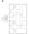
- FIG. 2 is a schematic diagram showing a driving environment of a host vehicle to which an embodiment is applied.
- 1 is a block diagram showing a functional configuration of an autonomous driving device according to an embodiment.
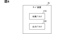
- 1 is a block diagram showing a functional configuration of an evacuation information generating system according to an embodiment;
- 1 is a flowchart showing a flow executed by an information processing device in an embodiment.
- 10 is a flowchart showing a flow in an area search mode executed by an information processing device according to an embodiment.
- 11 is a flowchart illustrating a flow in a disrupted device search mode executed by an information processing device according to an embodiment.
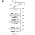
- 10 is a flowchart illustrating a flow executed by a server device according to an embodiment.
- FIG. 1 is a block diagram showing an overall configuration of an embodiment
- FIG. 2 is a schematic diagram showing a driving environment of a host vehicle to which an embodiment is applied.
- 1 is a block diagram showing
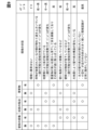
- FIG. 11 is a diagram showing an example of a hazard level according to observation information acquired in the area search mode.
- FIG. 13 is a diagram showing an example of a hazard level according to observation information acquired by a disruption device search mode.
- FIG. 13 is a diagram showing an example of a hazard map.
- the evacuation information generation system 3 of the first embodiment shown in Fig. 1 generates evacuation information related to a travel area A of an autonomous mobile device 1 shown in Fig. 2.
- the evacuation information generation system 3 is configured to include, for example, a plurality of autonomous mobile devices 1 and a server device 2b provided in a remote center 2 that manages the operation of the autonomous mobile devices 1.
- the autonomous driving device 1 is an autonomous driving robot that can autonomously drive in any direction, forward, backward, left or right.
- the autonomous driving device 1 may be a logistics robot that normally drives autonomously in a driving area A, such as a facility such as a hospital or warehouse, to transport luggage.
- the autonomous driving device 1 may be a delivery robot that normally drives autonomously on a road, such as driving area A, to transport luggage to a delivery destination.
- the autonomous driving device 1 may be an information gathering robot that normally patrols driving area A, such as a facility or road, to collect specific information.
- the autonomous driving device 1 normally provides the services described above within driving area A, and when a hazard occurs, it collects in driving area A the observation information necessary for the evacuation information generation process in evacuation information generation system 3.
- a hazard is an event that may cause damage to driving area A.
- a hazard can also be described as an event that requires users of driving area A to evacuate from that area.
- hazards include disaster events such as earthquakes and fires.
- Driving area A in which a hazard occurs can also be referred to as a hazard area.
- the autonomous driving device 1 is equipped with a sensor system 10, a communication system 20, a map database 30, a driving system 40, and an information processing device 100, as shown in FIG. 3.
- the sensor system 10 acquires sensor information for the external and internal worlds of the autonomous driving device 1 that can be used by the information processing device 100.
- the sensor system 10 is configured to include an external sensor 11 and an internal sensor 12.
- the external sensor 11 acquires external information as sensor information from the external world that is the surrounding environment of the autonomous driving device 1.
- the external sensor 11 may be of a target detection type that detects targets that exist in the external world of the autonomous driving device 1.
- the target detection type external sensor 11 is at least one of the following types: a camera, LiDAR (Light Detection and Ranging/Laser Imaging Detection and Ranging), radar, and sonar.
- the external information acquired by the external sensor 11 is linked to the position information of the acquired location and sequentially stored in a storage medium such as the memory 101 of the autonomous driving device 1 or the memory 201 of the server device 2b.
- the internal sensor 12 acquires internal information as sensor information from the internal world, which is the internal environment of the autonomous driving device 1.
- the internal sensor 12 may be a physical quantity detection type that detects a specific physical quantity of motion in the internal world of the autonomous driving device 1.
- the physical quantity detection type internal sensor 12 is at least one type of sensor, such as a driving speed sensor, an acceleration sensor, or a gyro sensor.
- the communication system 20 acquires communication information that can be used by the information processing device 100 through wireless communication.
- the communication system 20 includes a positioning type that receives positioning signals from artificial satellites of the Global Navigation Satellite System (GNSS) that exist in the external world of the autonomous driving device 1.
- the positioning type communication system 20 is, for example, a GNSS receiver.
- the communication system 20 includes a wide-area communication type that transmits and receives communication signals between a wide-area communication system that exists in the external world of the autonomous driving device 1.
- the wide-area communication type communication system 20 is, for example, at least one of a DSRC (Dedicated Short Range Communications) communication device and a Cellular V2X (C-V2X) communication device.
- DSRC Dedicated Short Range Communications
- C-V2X Cellular V2X
- the autonomous driving device 1 periodically provides its own position information to the remote center 2.
- the communication system 20 includes a short-distance communication type that transmits and receives signals by local communication between autonomous driving devices 1 that are relatively close to each other.
- the short-range communication type communication system 20 is at least one of the following: a Bluetooth (registered trademark) device, a Wi-Fi (registered trademark) device, and an infrared communication device.
- the map database 30 stores map information that can be used by the information processing device 100.
- the map database 30 is configured to include at least one type of non-transitory tangible storage medium, for example, semiconductor memory, magnetic medium, optical medium, etc.
- the map database 30 may be a database of a locator that estimates the self-state quantities including the self-position of the autonomous mobile device 1.
- the map database 30 may be a database of a planning unit that plans the travel of the autonomous mobile device 1.
- the map database 30 may be configured by combining multiple types of these databases, etc.
- the map database 30 acquires and stores the latest map information, for example, by communicating with the remote center 2 via the communication system 20.
- the map information is converted into two-dimensional or three-dimensional data as information representing the driving environment of the autonomous driving device 1.
- the map information may include facility information that indicates at least one of the following: the position, shape, and floor surface condition of the walls and floors of the facility along which the vehicle travels.
- the map information may include installation information that indicates at least one of the following: the position, shape, and type of installations attached to the facility.
- the map information may include road information that indicates at least one of the following: the position, shape, and road surface condition of the road along which the vehicle travels.
- the map information may include marking information that indicates at least one of the following: the position and shape of signs and dividing lines attached to the road.
- the map information may include structure information that indicates at least one of the following: the position and shape of buildings and traffic lights facing the road.
- the driving system 40 controls the driving of the autonomous driving device 1 in cooperation with the information processing device 100 and the like.
- the driving system 40 includes, for example, a plurality of drive wheels and an electric actuator that controls the drive wheels.
- the drive wheels are wheels that can turn due to the difference in rotational speed between the drive wheels, such as Mecanum wheels or omni wheels.
- the electric actuator can drive and rotate each drive wheel independently.
- the electric actuator can switch the drive mode of the autonomous driving device 1 between straight drive and turning drive by adjusting the difference in rotational speed between the drive wheels.
- the electric actuator may include a brake unit that applies braking to each drive wheel while it is rotating.
- the electric actuator may include a lock unit that locks each drive wheel while it is stopped.
- the information processing device 100 is connected to the sensor system 10, the communication system 20, and the map database 30 via at least one of the following: a LAN (Local Area Network) line, a wire harness, an internal bus, and a wireless communication line.
- the information processing device 100 is configured to include at least one dedicated computer.
- the dedicated computer constituting the information processing device 100 may be a planning ECU (Electronic Control Unit) that plans the target trajectory along which the autonomous driving device 1 will travel.
- the dedicated computer constituting the information processing device 100 may be a trajectory control ECU that causes the actual trajectory to follow the target trajectory of the autonomous driving device 1.
- the dedicated computer constituting the information processing device 100 may be an actuator ECU that controls each electric actuator of the autonomous driving device, etc.
- the dedicated computer constituting the information processing device 100 may be a sensing ECU that controls the sensor system 10 of the autonomous driving device 1.
- the dedicated computer constituting the information processing device 100 may be a locator ECU that estimates the self-state quantity of the autonomous driving device 1.
- the dedicated computer constituting the information processing device 100 may be a computer other than the autonomous driving device 1 that constitutes, for example, an external center or mobile terminal capable of communicating with the autonomous driving device 1 via the communication system 20.
- the dedicated computer constituting the information processing device 100 has at least one memory 101 and one processor 102.
- the memory 101 is at least one type of non-transitory tangible storage medium, such as a semiconductor memory, a magnetic medium, or an optical medium, that non-temporarily stores computer-readable programs and data.
- storage may mean accumulation in which data is retained even when the autonomous driving device 1 is turned off, or temporary storage in which data is erased when the autonomous driving device 1 is turned off.
- the processor 102 includes at least one type of core, such as a CPU (Central Processing Unit), a GPU (Graphics Processing Unit), a RISC (Reduced Instruction Set Computer)-CPU, a DFP (Data Flow Processor), or a GSP (Graph Streaming Processor).
- CPU Central Processing Unit
- GPU Graphics Processing Unit
- RISC Reduced Instruction Set Computer
- DFP Data Flow Processor
- GSP Graph Streaming Processor
- the processor 102 executes multiple commands contained in a search program stored in the memory 101 to execute search control that causes the autonomous driving device 1 to search driving area A where a hazard has occurred.
- the information processing device 100 constructs multiple functional blocks for search control.
- the multiple functional blocks constructed in the information processing device 100 include a search block 110 and a transmission block 120, as shown in FIG. 3.
- the search control method in which the information processing device 100 executes search control through the cooperation of these blocks 110 and 120 is executed according to the search control flow shown in Figures 5 to 7.
- This search control flow is executed repeatedly while the autonomous driving device 1 is running. Note that each "S" in this search control flow represents multiple steps executed by multiple commands included in the search control program.
- the search block 110 acquires hazard information.
- Hazard information is information that indicates the occurrence of a hazard. Therefore, the driving area A to which the hazard information applies is an area in which the occurrence of a hazard is predicted.
- the search block 110 acquires the hazard information, for example, from the remote center 2 via the communication system 20. Alternatively, the search block 110 may acquire the hazard information by determining the occurrence of a hazard based on information acquired from its own external sensor 11 and internal sensor 12.
- the search block 110 determines whether communication with the remote center 2 is possible.
- the search block 110 determines whether communication with the remote center 2 is possible by performing a fault diagnosis of the wide-area communication type communication system 20 and attempting communication with the remote center 2. If it is determined that communication is not possible, this flow ends.
- the autonomous mobile device 1 waits for a search from an autonomous mobile device 1 in an active state that can communicate with the remote center 2 (described below) as an autonomous mobile device 1 in a disconnected state.
- an autonomous mobile device 1 in a disconnected state may be referred to as a disconnected device.
- an autonomous mobile device 1 in an active state may be referred to as an active device. Note that, if the disconnected device can use a short-range communication type communication system 20, it may transmit a signal to the surrounding area by short-range communication to assist the search by the active device.
- the search block 110 determines whether the autonomous driving device 1 is capable of driving.
- the search block 110 may determine whether it is capable of driving by, for example, performing a fault diagnosis of the sensor system 10 or the driving system 40. If it is determined that driving is not possible, the flow proceeds to S130.
- the transmission block 120 transmits a fault notification to the remote center 2 via the communication system 20 notifying that driving is not possible, and then ends the flow. Note that even if it is determined that driving is not possible, the autonomous driving device 1 may transmit observation information (described later) around the current stopping position to the remote center 2 as long as the external sensor 11 is available.
- the search block 110 determines the search mode of the autonomous driving device 1. For example, the search block 110 determines the search mode by obtaining a mode designation command from the remote center 2. Search modes include, for example, an area search mode and a disrupted device search mode. If the mode is determined to be the area search mode, the flow proceeds to S150. If the mode is determined to be the disrupted device search mode, the flow proceeds to S160.
- the autonomous driving device 1 When executing the area search mode at S150, the autonomous driving device 1 searches for facilities that make up the driving area A and transmits the search results to the remote center 2.
- the detailed processing at S150 will be explained below with reference to the flowchart in FIG. 6.
- the search block 110 acquires external environment information for the travel area A after the hazard. More specifically, the search block 110 drives the autonomous driving device 1 near a location in the travel area A where observation information, described below, has not yet been acquired, and acquires external environment information for that location from the external environment sensor 11. At this time, the search block 110 may, for example, drive the autonomous driving device 1 so as to trace the location where external environment information was acquired before the hazard occurred. Alternatively, the search block 110 may drive the autonomous driving device 1 so as to continue proceeding along the planned travel route before the hazard occurred. Alternatively, the search block 110 may drive the autonomous driving device 1 so as to proceed along the planned travel route distributed from the remote center 2 after the hazard occurred. The search block 110 acquires the external environment information by linking it to the position information of the location.
- the search block 110 acquires pre-hazard external world information relating to the location for which the external world information was acquired in S151.
- the search block 110 acquires pre-hazard external world information by reading pre-hazard external world information from the storage medium whose position information substantially matches the external world information acquired in S151. Note that the pre-hazard external world information may have been acquired by another autonomous driving device 1.
- the transmission block 120 outputs observation information corresponding to the external world information before and after the hazard to the remote center 2. More specifically, the transmission block 120 outputs, as observation information, difference information between the external world information acquired in the area search and the external world information before the hazard. The observation information may also include an analysis result for the difference. The output observation information is transmitted to the remote center 2 via the communication system 20. After the processing of S153, this flow proceeds to S170 in FIG. 5.
- the autonomous mobile device 1 searches for a disrupted device and transmits the search results to the remote center 2.
- the detailed processing in S160 will be explained with reference to the flowchart in FIG. 7.
- the search block 110 starts traveling to search for the disrupted device.
- the search block 110 acquires location information on the disrupted device immediately before the disruption from the remote center 2 or the like, and controls the traveling system 40 to head toward the disruption location where the disrupted device is estimated to be present.
- the disruption location is, for example, an area of a specified range that includes the location coordinates immediately before the disruption.
- the search block 110 determines whether the autonomous driving device 1 has arrived at the disruption location. The search block 110 continues searching for the disruption location until it determines that the autonomous driving device 1 has arrived at the disruption location. If it determines that the autonomous driving device 1 has arrived at the disruption location, the flow proceeds to S163.
- the search block 110 executes a diagnostic process regarding the state of the disrupted device at the disruption location.
- the search block 110 determines whether local communication is possible between the active device (own device) and the disrupted device, for example, by a short-range communication type communication system 20.
- the search block 110 determines whether the external sensor 11 of the own device can recognize the disrupted device.
- the search block 110 determines the degree of damage to the appearance of the disrupted device.
- the transmission block 120 outputs the diagnostic information of the interrupted device acquired in S163 as observation information.
- the output observation information is transmitted to the remote center 2 via the communication system 20.
- the flow proceeds to S170 in FIG. 5.
- the search block 110 determines whether there is an instruction to end the search.
- the end instruction is sent to the autonomous mobile device 1 in response to the operation of a manager such as an operator at the remote center 2, for example. If there is no end instruction, the search block 110 executes the area search mode in S150. That is, the autonomous mobile device 1 in the area search mode expands the area search area within the facility until an end instruction is issued. Then, the autonomous mobile device 1 in the disconnected device search mode transitions to the area search mode if there is no end instruction after searching for a disconnected device. As a result, the proportion of devices executing the area search mode among the autonomous mobile devices 1 in the active state increases over time. When an end instruction is acquired, this flow ends and the search process is completed. After the search ends, the autonomous mobile device 1 may wait at the search end point, or may leave the travel area A in response to evacuation information from the remote center 2.
- the server device 2b is connected to the communicator 2a that communicates with the autonomous mobile device 1 via at least one of, for example, a LAN line, a wire harness, an internal bus, and a wireless communication line.
- the server device 2b is configured to include at least one dedicated computer.
- the dedicated computer constituting the server device 2b has at least one memory 201 and one processor 202.
- the memory 201 is at least one type of non-transient tangible storage medium, such as a semiconductor memory, a magnetic medium, or an optical medium, that non-temporarily stores computer-readable programs and data.
- storage may mean accumulation in which data is retained even when the dedicated computer is turned off, or temporary storage in which data is erased when the dedicated computer is turned off.
- the processor 202 includes at least one type of core, such as a CPU, GPU, RISC-CPU, DFP, or GSP.
- server device 2b processor 202 executes a plurality of instructions contained in an evacuation information generation program stored in memory 201 in order to generate evacuation information for travel area A of autonomous driving device 1.
- server device 2b constructs a plurality of functional blocks for generating evacuation information for travel area A.
- the plurality of functional blocks constructed in evacuation information generation system 3 include a collection block 210 and an output block 220, as shown in FIG. 4.
- the evacuation information generation method in which the server device 2b generates evacuation information for the driving area A of the autonomous driving device 1 by cooperation of these blocks 210 and 220 is executed according to the evacuation information generation flow shown in FIG. 8.
- This evacuation information generation flow is executed repeatedly while the dedicated computer is running. Note that each "S" in this evacuation information generation flow represents multiple steps executed by multiple commands included in the evacuation information generation program.
- the collection block 210 determines whether a hazard has occurred.
- the collection block 210 may determine the occurrence of a hazard when hazard occurrence information is acquired from at least one of the following sources: distribution from a public communication network such as the Internet, a report from a facility, and information provided by a fire department or the like.
- the collection block 210 waits for the flow to proceed until it determines that an event has occurred. If it determines that a hazard has occurred, the flow proceeds to S210.
- the output block 220 outputs the hazard information to the autonomous mobile device 1.
- the hazard information is transmitted to each autonomous mobile device 1 in the travel area A via the communication device 2a.
- the collection block 210 executes allocation of search modes to the autonomous mobile devices 1 in the travel area A. Specifically, the collection block 210 identifies active devices without fault notifications, i.e., autonomous mobile devices 1 that are capable of traveling, by communicating with the autonomous mobile devices 1. The collection block 210 then allocates the identified autonomous mobile devices 1 to devices that execute the area search mode and devices that execute the disrupted device search mode. For example, the collection block 210 may allocate the disrupted device search mode to the autonomous mobile device 1 closest to each disruption location, and allocate the other autonomous mobile devices 1 to the area search mode. The collection block 210 may assign multiple autonomous mobile devices 1 to one disruption location. The collection block 210 outputs the allocation result to each autonomous mobile device 1, causing each autonomous mobile device 1 to execute the search mode corresponding to it.
- active devices without fault notifications i.e., autonomous mobile devices 1 that are capable of traveling
- the collection block 210 then allocates the identified autonomous mobile devices 1 to devices that execute the area search mode and devices that execute the disrupted device search mode. For example, the collection
- step S230 the collection block 210 acquires observation information from an area search from each autonomous mobile device 1 that is active.
- step S240 the collection block 210 acquires observation information from a search for a disrupted device from each autonomous mobile device 1 that is active. Note that the processing of steps S230 and S240 may be performed in parallel.
- the collection block 210 continues the acquisition process until sufficient location observation information has been collected to generate a hazard map, and then proceeds to step S250.
- the output block 220 generates a hazard map according to each piece of observation information.
- the hazard map is evacuation information in map format that indicates the hazard level for each location within the driving area A.
- the hazard level is the degree of danger to the user of the driving area A.
- the user is, for example, a person.
- the user may be the autonomous driving device 1.
- the output block 220 may estimate the hazard level for each type of user.
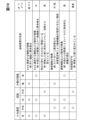
- the output block 220 estimates the hazard level of the corresponding location from each piece of observation information. For example, as shown in FIG. 11, the output block 220 estimates the hazard level for each location, which is a small section of the driving area A, according to the observation information for the corresponding position.
- the output block 220 sets multiple hazard levels according to information from the observation information.
- the output block 220 sets five hazard levels, from lowest to highest, which are zero, low, medium, high, and the highest level of danger.
- the magnitude of the hazard level is the same for both people and the autonomous driving device 1.
- the output block 220 determines whether there is damage to nearby walls, whether there are cave-ins in the floor, and whether there are obstacles on the floor for each location based on the observation information obtained by area search, and determines the hazard level based on the state of the location estimated from the results of the determination.
- the output block 220 determines that there is no wall damage, no floor collapse, and no obstacle, it presumes that there is no abnormality in that location. In this case, the output block 220 determines the hazard level to be zero. Also, if the output block 220 determines that there is an obstacle without any wall damage or floor collapse, it determines the hazard level for that location to be between low and high. The smaller the passable area is due to an obstacle, the higher the hazard level the output block 220 determines for that area and the obstacle position. The output block 220 may determine the hazard levels for the obstacle position and the passable area separately.
- the output block 220 determines that there is no damage to the walls, that there is a collapsed floor, and that there are no obstacles, it presumes that the floor is missing at that location. In this case, the output block 220 determines the hazard level to be between medium and high. The smaller the passable area is due to a collapsed floor, the higher the hazard level the output block 220 determines for that area and the collapsed part. The output block 220 may determine the hazard levels for the collapsed part and the passable area separately.
- the output block 220 determines that there is no damage to the walls, that there is a collapsed floor, and that there is an obstacle, it presumes that the floor at that location has been damaged by a fallen heavy object, and that the heavy object or its fragments are scattered on the floor. In this case, the output block 220 determines the hazard level to be high. Furthermore, if the output block 220 determines that there is damage to the walls, that there is no collapsed floor, and that there are no obstacles, it determines the hazard level at that location to be low.
- the output block 220 determines that there is damage to the wall, no collapse in the floor, and the presence of an obstacle, it presumes that an object installed on the wall at that location has fallen onto the floor. In this case, the output block 220 determines the hazard level to be low to medium. The smaller the passable area becomes due to the falling object, the higher the hazard level the output block 220 determines for that area and the position of the falling object. The output block 220 may determine the hazard levels for the position of the falling object and the passable area separately.
- the output block 220 determines that there is wall damage, a floor collapse, and no obstacles, it presumes that the structure of the wall or floor has changed due to the hazard. In this case, the output block 220 determines the hazard level to be high. Also, if the output block 220 determines that there is wall damage, a floor collapse, and/or an obstacle, it presumes that the shape of the wall or floor has not been maintained due to the hazard, or that the floor has been significantly deformed and environmental recognition is not being performed normally. In this case, the output block 220 determines the hazard level to be the highest.
- the output block 220 determines the status of the disrupted device from the observation information obtained by searching for the disrupted device. For example, the output block 220 determines whether local communication is possible with the disrupted device, whether the disrupted device has been found, and whether the external appearance of the disrupted device is damaged. The output block 220 determines the hazard level at the disruption location from the status of the disrupted device estimated from the determination result.
- the output block 220 determines that local communication is possible, that it has been found, and that there is no external damage, it determines that only the disruption device's communication function with the center is damaged. In this case, the output block 220 determines the hazard level for people to be zero. In this case, the output block 220 also sets the hazard level for the autonomous driving device 1 to low. In addition, if the output block 220 determines that local communication is possible, that it has been found, and that there is external damage, it presumes that the disruption device's communication function with the center and its casing have been damaged by an external impact. In this case, the output block 220 determines the hazard level to be medium.
- the output block 220 determines that local communication is possible, but that the device has not been found and it is not possible to determine whether there is any external damage, it presumes that the disrupted device has been left behind in an area where other autonomous driving devices 1 cannot enter. In this case, the output block 220 determines the hazard level to be high.
- the output block 220 determines that local communication is not possible, that a detection has occurred, and that there is no external damage, it presumes that the communication function is not available due to an abnormality in the network card, the generation of jamming radio waves, etc. In this case, the output block 220 determines the hazard level for people to be low. Also, in this case, the output block 220 determines the hazard level for the autonomous mobile device 1 to be medium.
- the output block 220 determines that local communication is not possible, that the device has been found, and that there is external damage, it presumes that serious damage has occurred to the hardware of the disruption device due to an external impact. In this case, the output block 220 determines the hazard level to be high. Then, if the output block 220 determines that it is not possible to determine whether there is external damage because local communication is not possible and the device has not been found, it presumes that the status of the disruption device cannot be confirmed because it has been caught up in the collapse of a facility, for example. In this case, the output block 220 determines the hazard level to be the highest.
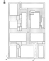
- the output block 220 By setting the hazard level for each location as described above, the output block 220 generates a hazard map M in which a hazard level is defined for each subdivision, as shown in FIG. 11. In FIG. 11, the darker the hatching of the dots, the higher the hazard level. Subdivisions with no hatching are locations where the hazard level is set to zero.
- the output block 220 In the next step S260, the output block 220 generates evacuation route data within the driving area A.
- the evacuation route data is evacuation information in a map format that represents the evacuation route Re within the driving area A.
- the output block 220 generates the evacuation route data based on the hazard map M generated in S250.
- the output block 220 searches for a route with the smallest hazard cost from a specified starting point to the exit of the travel area A, and sets the route as the evacuation route Re.
- the starting point of the evacuation route Re is, for example, the current location of an evacuee detected in the travel area A.
- the evacuation route Re may start at any position.
- the starting point of the hazard cost is a cost according to the hazard level in the hazard map M.
- the hazard cost is a parameter related to the sum of the hazard levels of each location passed through, which is quantified so that the higher the level, the larger the value. Note that in the example shown in FIG.
- the evacuation route Re with the lowest hazard level (zero) is shown, but it is also possible to pass through locations with a hazard level greater than zero as long as the hazard cost is minimized.
- the output block 220 may generate evacuation route data with a constraint that locations with a hazard level or higher than a specified hazard level are not passed through regardless of the hazard cost.
- the output block 220 outputs the hazard map M and evacuation route data.
- the output block 220 may output this evacuation information to a rescue organization such as a fire department.
- the output block 220 may output this evacuation information to the autonomous mobile device 1 in the travel area A.
- the output block 220 may output this evacuation information to personnel such as an operator at the remote center 2.
- the output block 220 outputs the evacuation route data in association with the hazard map M.
- the output block 220 associates the data so that the position of the evacuation route Re is presented on the hazard map M, as shown in FIG. 11.
- a hazard map M is output according to observation information by the autonomous driving device for a driving area A where the occurrence of a hazard is predicted. Therefore, the hazard map M for each location can reflect actual observation information for that location. Therefore, effective evacuation information can be generated.
- route evacuation data corresponding to observation information by the autonomous driving device regarding driving area A where the occurrence of a hazard is predicted is output. Therefore, actual observation information can be reflected in the evacuation route data within driving area A. Therefore, effective evacuation information can be generated.
- evacuation route data is output in association with the hazard map M. Therefore, highly convenient evacuation information that allows users to grasp both the hazard level and evacuation route data can be provided.
- acquiring observation information includes acquiring observation information obtained by searching the travel area A using an active device that can communicate with the outside, among the multiple autonomous driving devices 1. Therefore, evacuation information can be generated using an active device that can communicate with the outside.
- acquiring observation information includes acquiring observation information by searching for the facilities that make up the travel area A using an active device. This makes it possible to generate evacuation information according to damage to the travel area A caused by a hazard.
- acquiring the observation information includes acquiring the observation information obtained by searching for a disconnected device that has lost communication with the outside world within the travel area A among the multiple autonomous driving devices 1 using an active device. Then, outputting the evacuation information includes outputting a hazard map M that indicates the hazard level of the location where the disconnected device is estimated to be present as a hazard level according to the state of the searched disconnected device. Therefore, by utilizing the active device, evacuation information according to the state of the disconnected device can be generated.
- outputting evacuation information includes outputting a hazard map M that indicates a hazard level according to the state of mutual communication between the active device and the disconnected device. Therefore, evacuation information can be generated that utilizes the state of mutual communication between the active device and the disconnected device.
- outputting evacuation information includes outputting a hazard map M that indicates a hazard level according to the observation state of the disruption device by the active device.
- evacuation information according to the observation state of the disruption device can be generated by utilizing the active device.
- some of the functions executed by the server device 2b may be executed by another control device, such as the information processing device 100 of the autonomous driving device 1. Also, in a modified example, some of the functions executed by the information processing device 100 may be executed outside the autonomous driving device 1, such as the remote center 2.
- the evacuation information generating system 3 may output only one of the hazard map M and the evacuation route data.
- the dedicated computer constituting the evacuation information generating system 3 may have at least one of a digital circuit and an analog circuit as a processor.
- the digital circuit is at least one of the following types: ASIC (Application Specific Integrated Circuit), FPGA (Field Programmable Gate Array), SOC (System on a Chip), PGA (Programmable Gate Array), and CPLD (Complex Programmable Logic Device).
- ASIC Application Specific Integrated Circuit
- FPGA Field Programmable Gate Array
- SOC System on a Chip
- PGA Programmable Gate Array
- CPLD Complex Programmable Logic Device
- the above-mentioned embodiments and modified examples may be implemented as an evacuation information generating device that is configured to be mountable on the autonomous driving device 1 or the remote center 2 and has at least one processor and one memory.
- the evacuation information generating device may be implemented in the form of a processing circuit (e.g., a processing ECU, etc.) or a semiconductor device (e.g., a semiconductor chip, etc.).
- An evacuation information generation system having a processor (202; 102) and generating evacuation information for a travel area (A) of an autonomous mobile device (1), The processor, acquiring observation information observed by searching the travel area where a hazard is estimated to occur using the autonomous traveling device; outputting a hazard map (M) representing a hazard level for each location in the travel area according to the observation information; An evacuation information generating system configured to execute the above.
- the evacuation information generating system according to technical idea 1 includes outputting evacuation route data within the driving area based on the hazard map.
- Outputting the evacuation information includes:
- the evacuation information generating system according to technical idea 2 includes outputting the evacuation route data in correspondence with the hazard map.
- An evacuation information generation system having a processor (202; 102) and generating evacuation information for a travel area (A) of an autonomous mobile device (1), The processor, acquiring observation information observed by searching the travel area where a hazard is estimated to occur using the autonomous traveling device; outputting evacuation route data within the travel area in response to the observation information; An evacuation information generating system configured to execute the above.
- the acquiring of the observation information includes: An evacuation information generation system described in any one of technical ideas 1 to 4, which includes acquiring the observation information by searching the driving area using an active device capable of communicating with the outside, among the multiple autonomous driving devices.
- the acquiring of the observation information includes:
- the evacuation information generating system described in technical idea 5 includes acquiring the observation information by searching for facilities that make up the travel area using the active device.
- the acquiring of the observation information includes: The method includes acquiring the observation information obtained by searching for a lost device that has lost communication with the outside within the travel area among the plurality of autonomous driving devices by the active device; Outputting the evacuation information includes: An evacuation information generating system as described in Technical Idea 5 or Technical Idea 6, which includes outputting a hazard map (M) representing the hazard level of a location where the existence of the disruption device is estimated as a hazard level according to the state of the detected disruption device.
- M hazard map
- the active device is the autonomous driving device capable of communicating with a remote center (2)
- the disconnected device is the autonomous driving device that has lost communication with the remote center
- Outputting the evacuation information includes:
- the evacuation information generating system described in technical idea 7 includes outputting a hazard map showing the hazard level according to the intercommunication state between the active device and the disconnected device.
- Outputting the evacuation information includes:
- the evacuation information generating system described in Technical Idea 7 or Technical Idea 8 includes outputting a hazard map showing the hazard level according to the observation state of the disconnection device by the active device.
Landscapes
- Engineering & Computer Science (AREA)
- General Physics & Mathematics (AREA)
- Physics & Mathematics (AREA)
- Radar, Positioning & Navigation (AREA)
- Remote Sensing (AREA)
- Automation & Control Theory (AREA)
- Aviation & Aerospace Engineering (AREA)
- Business, Economics & Management (AREA)
- Computing Systems (AREA)
- Health & Medical Sciences (AREA)
- General Business, Economics & Management (AREA)
- General Health & Medical Sciences (AREA)
- Economics (AREA)
- Biomedical Technology (AREA)
- Toxicology (AREA)
- Environmental & Geological Engineering (AREA)
- Theoretical Computer Science (AREA)
- Emergency Management (AREA)
- Operations Research (AREA)
- Accounting & Taxation (AREA)
- Development Economics (AREA)
- Control Of Position, Course, Altitude, Or Attitude Of Moving Bodies (AREA)
- Alarm Systems (AREA)
- Traffic Control Systems (AREA)
- Management, Administration, Business Operations System, And Electronic Commerce (AREA)
Abstract
Description
プロセッサは、
ハザードの発生が推定される走行エリアを自律走行装置により探索することで観測された観測情報を取得することと、
観測情報に応じて、走行エリア内におけるロケーションごとのハザードレベルを表すハザードマップとしての避難情報を出力することと、
を実行するように構成される。
プロセッサは、
ハザードの発生が推定される走行エリアを自律走行装置により探索することで観測された観測情報を取得することと、
観測情報に応じて、走行エリア内におけるロケーションごとのハザードレベルを表すハザードマップとしての避難情報を出力することと、
を実行するように構成される。
プロセッサは、
ハザードの発生が推定される走行エリアを自律走行装置により探索することで観測された観測情報を取得することと、
観測情報に応じて、走行エリア内におけるロケーションごとのハザードレベルを表すハザードマップとしての避難情報を出力することと、
を実行するように構成される。
ハザードの発生が推定される走行エリアを自律走行装置により探索することで観測された観測情報を取得することと、
観測情報に応じて、走行エリア内におけるロケーションごとのハザードレベルを表すハザードマップとしての避難情報を出力することと、
を含む。
命令は、
ハザードの発生が推定される走行エリアを自律走行装置により探索することで観測された観測情報を取得させることと、
観測情報に応じて、走行エリア内におけるロケーションごとのハザードレベルを表すハザードマップとしての避難情報を出力させることと、
を含む。
プロセッサは、
ハザードの発生が推定される走行エリアを自律走行装置により探索することで観測された観測情報を取得することと、
観測情報に応じて、走行エリア内における避難経路データとしての避難情報を出力することと、
を実行するように構成される。
プロセッサは、
ハザードの発生が推定される走行エリアを自律走行装置により探索することで観測された観測情報を取得することと、
観測情報に応じて、走行エリア内における避難経路データとしての避難情報を出力することと、
を実行するように構成される。
プロセッサは、
ハザードの発生が推定される走行エリアを自律走行装置により探索することで観測された観測情報を取得することと、
観測情報に応じて、走行エリア内における避難経路データとしての避難情報を出力することと、
を実行するように構成される。
ハザードの発生が推定される走行エリアを自律走行装置により探索することで観測された観測情報を取得することと、
観測情報に応じて、走行エリア内における避難経路データとしての避難情報を出力することと、
を含む。
命令は、
ハザードの発生が推定される走行エリアを自律走行装置により探索することで観測された観測情報を取得させることと、
観測情報に応じて、走行エリア内における避難経路データとしての避難情報を出力させることと、
を含む。
図1に示す第一実施形態の避難情報生成システム3は、図2に示す自律走行装置1の走行エリアAに関する避難情報を生成する。避難情報生成システム3は、例えば複数の自律走行装置1と、自律走行装置1の運行を管理するリモートセンタ2において設けられるサーバ装置2bと、を含んで構成されている。
以上、一実施形態について説明したが、本開示は、当該説明の実施形態に限定して解釈されるものではなく、本開示の要旨を逸脱しない範囲内において種々の実施形態に適用することができる。
この明細書には、以下に列挙する複数の技術的思想と、それらの複数の組み合わせが開示されている。
プロセッサ(202;102)を有し、自律走行装置(1)の走行エリア(A)における避難情報を生成する避難情報生成システムであって、
前記プロセッサは、
ハザードの発生が推定される前記走行エリアを前記自律走行装置により探索することで観測された観測情報を取得することと、
前記観測情報に応じて、前記走行エリア内におけるロケーションごとのハザードレベルを表すハザードマップ(M)を出力することと、
を実行するように構成される避難情報生成システム。
前記避難情報を出力することは、
前記ハザードマップに基づく前記走行エリア内における避難経路データを、出力することを含む技術的思想1に記載の避難情報生成システム。
前記避難情報を出力することは、
前記避難経路データを前記ハザードマップに対応付けて出力することを含む技術的思想2に記載の避難情報生成システム。
プロセッサ(202;102)を有し、自律走行装置(1)の走行エリア(A)における避難情報を生成する避難情報生成システムであって、
前記プロセッサは、
ハザードの発生が推定される前記走行エリアを前記自律走行装置により探索することで観測された観測情報を取得することと、
前記観測情報に応じて、前記走行エリア内における避難経路データを出力することと、
を実行するように構成される避難情報生成システム。
前記観測情報を取得することは、
複数の前記自律走行装置のうち、外部と通信可能な活装置により前記走行エリアを探索した、前記観測情報を取得することを含む技術的思想1から技術的思想4のいずれか1項に記載の避難情報生成システム。
前記観測情報を取得することは、
前記活装置により前記走行エリアを構成する設備を探索した、前記観測情報を取得することを含む技術的思想5に記載の避難情報生成システム。
前記観測情報を取得することは、
複数の前記自律走行装置のうち前記走行エリア内にて外部と通信途絶した途絶装置を、前記活装置により探索した、前記観測情報を取得することを含み、
前記避難情報を出力することは、
探索された前記途絶装置の状態に応じたハザードレベルとして、前記途絶装置の存在が推定されるロケーションの前記ハザードレベルを表すハザードマップ(M)を出力することを含む技術的思想5又は技術的思想6に記載の避難情報生成システム。
前記活装置はリモートセンタ(2)と通信可能な前記自律走行装置であり、且つ前記途絶装置は前記リモートセンタと通信途絶した前記自律走行装置であって、
前記避難情報を出力することは、
前記活装置と前記途絶装置との相互通信状態に応じた前記ハザードレベルを表す前記ハザードマップを出力することを含む技術的思想7に記載の避難情報生成システム。
前記避難情報を出力することは、
前記活装置による前記途絶装置の観測状態に応じた前記ハザードレベルを表す前記ハザードマップを出力することを含む技術的思想7又は技術的思想8に記載の避難情報生成システム。
Claims (17)
- プロセッサ(202;102)を有し、自律走行装置(1)の走行エリア(A)における避難情報を生成する避難情報生成システムであって、
前記プロセッサは、
ハザードの発生が推定される前記走行エリアを前記自律走行装置により探索することで観測された観測情報を取得することと、
前記観測情報に応じて、前記走行エリア内におけるロケーションごとのハザードレベルを表すハザードマップ(M)としての避難情報を出力することと、
を実行するように構成される避難情報生成システム。 - 前記避難情報を出力することは、
前記ハザードマップに基づく前記走行エリア内における避難経路データを、出力することを含む請求項1に記載の避難情報生成システム。 - 前記避難情報を出力することは、
前記避難経路データを前記ハザードマップに対応付けて出力することを含む請求項2に記載の避難情報生成システム。 - プロセッサ(202;102)を有し、自律走行装置(1)の走行エリア(A)における避難情報を生成する避難情報生成システムであって、
前記プロセッサは、
ハザードの発生が推定される前記走行エリアを前記自律走行装置により探索することで観測された観測情報を取得することと、
前記観測情報に応じて、前記走行エリア内における避難経路データとしての避難情報を出力することと、
を実行するように構成される避難情報生成システム。 - 前記観測情報を取得することは、
複数の前記自律走行装置のうち、外部と通信可能な活装置により前記走行エリアを探索した、前記観測情報を取得することを含む請求項1から請求項4のいずれか1項に記載の避難情報生成システム。 - 前記観測情報を取得することは、
前記活装置により前記走行エリアを構成する設備を探索した、前記観測情報を取得することを含む請求項5に記載の避難情報生成システム。 - 前記観測情報を取得することは、
複数の前記自律走行装置のうち前記走行エリア内にて外部と通信途絶した途絶装置を、前記活装置により探索した、前記観測情報を取得することを含み、
前記避難情報を出力することは、
探索された前記途絶装置の状態に応じたハザードレベルとして、前記途絶装置の存在が推定されるロケーションの前記ハザードレベルを表すハザードマップ(M)を出力することを含む請求項5に記載の避難情報生成システム。 - 前記活装置はリモートセンタ(2)と通信可能な前記自律走行装置であり、且つ前記途絶装置は前記リモートセンタと通信途絶した前記自律走行装置であって、
前記避難情報を出力することは、
前記活装置と前記途絶装置との相互通信状態に応じた前記ハザードレベルを表す前記ハザードマップを出力することを含む請求項7に記載の避難情報生成システム。 - 前記避難情報を出力することは、
前記活装置による前記途絶装置の観測状態に応じた前記ハザードレベルを表す前記ハザードマップを出力することを含む請求項7に記載の避難情報生成システム。 - プロセッサ(202;102)を有し、自律走行装置(1)又はリモートセンタ(2)に設置可能に構成され、自律走行装置(1)の走行エリア(A)における避難情報を生成する避難情報生成装置であって、
前記プロセッサは、
ハザードの発生が推定される前記走行エリアを前記自律走行装置により探索することで観測された観測情報を取得することと、
前記観測情報に応じて、前記走行エリア内におけるロケーションごとのハザードレベルを表すハザードマップ(M)としての避難情報を出力することと、
を実行するように構成される避難情報生成装置。 - プロセッサ(202;102)を有し、自律走行装置(1)又はリモートセンタ(2)に設置可能に構成され、自律走行装置(1)の走行エリア(A)における避難情報を生成する避難情報生成装置であって、
前記プロセッサは、
ハザードの発生が推定される前記走行エリアを前記自律走行装置により探索することで観測された観測情報を取得することと、
前記観測情報に応じて、前記走行エリア内における避難経路データとしての避難情報を出力することと、
を実行するように構成される避難情報生成装置。 - プロセッサ(102)を有し、走行エリア(A)を自律走行する自律走行装置であって、
前記プロセッサは、
ハザードの発生が推定される前記走行エリアを前記自律走行装置により探索することで観測された観測情報を取得することと、
前記観測情報に応じて、前記走行エリア内におけるロケーションごとのハザードレベルを表すハザードマップ(M)としての避難情報を出力することと、
を実行するように構成される自律走行装置。 - プロセッサ(102)を有し、走行エリア(A)を自律走行する自律走行装置(1)であって、
前記プロセッサは、
ハザードの発生が推定される前記走行エリアを前記自律走行装置により探索することで観測された観測情報を取得することと、
前記観測情報に応じて、前記走行エリア内における避難経路データとしての避難情報を出力することと、
を実行するように構成される自律走行装置。 - 自律走行装置(1)の走行エリア(A)における避難情報を生成するために、プロセッサ(202;102)により実行される避難情報生成方法であって、
ハザードの発生が推定される前記走行エリアを前記自律走行装置により探索することで観測された観測情報を取得することと、
前記観測情報に応じて、前記走行エリア内におけるロケーションごとのハザードレベルを表すハザードマップ(M)としての避難情報を出力することと、
を含む避難情報生成方法。 - 自律走行装置(1)の走行エリア(A)における避難情報を生成するために、プロセッサ(202;102)により実行される避難情報生成方法であって、
ハザードの発生が推定される前記走行エリアを前記自律走行装置により探索することで観測された観測情報を取得することと、
前記観測情報に応じて、前記走行エリア内における避難経路データとしての避難情報を出力することと、
を含む避難情報生成方法。 - 自律走行装置(1)の走行エリア(A)における避難情報を生成するために記憶媒体(201;101)に記憶され、プロセッサ(202;102)に実行させる命令を含む避難情報生成プログラムであって、
前記命令は、
ハザードの発生が推定される前記走行エリアを前記自律走行装置により探索することで観測された観測情報を取得させることと、
前記観測情報に応じて、前記走行エリア内におけるロケーションごとのハザードレベルを表すハザードマップ(M)としての避難情報を出力させることと、
を含む避難情報生成プログラム。 - 自律走行装置(1)の走行エリア(A)における避難情報を生成するために記憶媒体(201;101)に記憶され、プロセッサ(202;102)に実行させる命令を含む避難情報生成プログラムであって、
前記命令は、
ハザードの発生が推定される前記走行エリアを前記自律走行装置により探索することで観測された観測情報を取得させることと、
前記観測情報に応じて、前記走行エリア内における避難経路データとしての避難情報を出力させることと、
を含む避難情報生成プログラム。
Priority Applications (2)
| Application Number | Priority Date | Filing Date | Title |
|---|---|---|---|
| CN202380070575.8A CN119998855A (zh) | 2022-10-03 | 2023-09-12 | 避难信息生成系统、避难信息生成装置、自主行驶装置、避难信息生成方法以及避难信息生成程序 |
| US19/095,614 US20250225847A1 (en) | 2022-10-03 | 2025-03-31 | Evacuation information generation system, evacuation information generation device, autonomous traveling device, evacuation information generation method |
Applications Claiming Priority (2)
| Application Number | Priority Date | Filing Date | Title |
|---|---|---|---|
| JP2022-159744 | 2022-10-03 | ||
| JP2022159744A JP7768084B2 (ja) | 2022-10-03 | 2022-10-03 | 避難情報生成システム、避難情報生成装置、自律走行装置、避難情報生成方法、避難情報生成プログラム |
Related Child Applications (1)
| Application Number | Title | Priority Date | Filing Date |
|---|---|---|---|
| US19/095,614 Continuation US20250225847A1 (en) | 2022-10-03 | 2025-03-31 | Evacuation information generation system, evacuation information generation device, autonomous traveling device, evacuation information generation method |
Publications (1)
| Publication Number | Publication Date |
|---|---|
| WO2024075477A1 true WO2024075477A1 (ja) | 2024-04-11 |
Family
ID=90607817
Family Applications (1)
| Application Number | Title | Priority Date | Filing Date |
|---|---|---|---|
| PCT/JP2023/033208 Ceased WO2024075477A1 (ja) | 2022-10-03 | 2023-09-12 | 避難情報生成システム、避難情報生成装置、自律走行装置、避難情報生成方法、避難情報生成プログラム |
Country Status (4)
| Country | Link |
|---|---|
| US (1) | US20250225847A1 (ja) |
| JP (1) | JP7768084B2 (ja) |
| CN (1) | CN119998855A (ja) |
| WO (1) | WO2024075477A1 (ja) |
Citations (2)
| Publication number | Priority date | Publication date | Assignee | Title |
|---|---|---|---|---|
| JP2018146474A (ja) * | 2017-03-08 | 2018-09-20 | アイシン・エィ・ダブリュ株式会社 | 道路情報提供システム、ナビゲーションシステム、道路情報提供プログラム |
| JP2021047482A (ja) * | 2019-09-17 | 2021-03-25 | トヨタ自動車株式会社 | 避難誘導システム |
Family Cites Families (1)
| Publication number | Priority date | Publication date | Assignee | Title |
|---|---|---|---|---|
| JPWO2018159259A1 (ja) | 2017-03-01 | 2019-12-19 | パナソニックIpマネジメント株式会社 | 車両 |
-
2022
- 2022-10-03 JP JP2022159744A patent/JP7768084B2/ja active Active
-
2023
- 2023-09-12 CN CN202380070575.8A patent/CN119998855A/zh active Pending
- 2023-09-12 WO PCT/JP2023/033208 patent/WO2024075477A1/ja not_active Ceased
-
2025
- 2025-03-31 US US19/095,614 patent/US20250225847A1/en active Pending
Patent Citations (2)
| Publication number | Priority date | Publication date | Assignee | Title |
|---|---|---|---|---|
| JP2018146474A (ja) * | 2017-03-08 | 2018-09-20 | アイシン・エィ・ダブリュ株式会社 | 道路情報提供システム、ナビゲーションシステム、道路情報提供プログラム |
| JP2021047482A (ja) * | 2019-09-17 | 2021-03-25 | トヨタ自動車株式会社 | 避難誘導システム |
Also Published As
| Publication number | Publication date |
|---|---|
| US20250225847A1 (en) | 2025-07-10 |
| CN119998855A (zh) | 2025-05-13 |
| JP7768084B2 (ja) | 2025-11-12 |
| JP2024053448A (ja) | 2024-04-15 |
Similar Documents
| Publication | Publication Date | Title |
|---|---|---|
| US11859990B2 (en) | Routing autonomous vehicles using temporal data | |
| US10655972B2 (en) | Method and device for operating a vehicle and a parking facility respectively | |
| US11661084B2 (en) | Information processing apparatus, information processing method, and mobile object | |
| JP7468404B2 (ja) | 自動運転車両、自動運転車両の配車システム及び携帯端末 | |
| JP2019500693A (ja) | 自律視覚ナビゲーション | |
| US11441913B2 (en) | Autonomous vehicle waypoint routing | |
| JP6891753B2 (ja) | 情報処理装置、移動装置、および方法、並びにプログラム | |
| JP2009205652A (ja) | 移動体制御システム及び移動体制御方法 | |
| CN110300706A (zh) | 飞行器-地面车辆协调 | |
| JP2020177289A (ja) | 情報処理装置、情報処理方法及び情報処理プログラム | |
| US12386071B2 (en) | Systems and methods for infant track association with radar detections for velocity transfer | |
| JP7135690B2 (ja) | 情報処理装置および方法、プログラム、並びに移動体制御システム | |
| CN110214344A (zh) | 交通工具管理系统 | |
| US20210095977A1 (en) | Revising self-driving vehicle routes in response to obstructions | |
| WO2023219058A1 (ja) | 情報処理方法、情報処理装置及び情報処理システム | |
| US20230280180A1 (en) | Systems and methods for performing data collection missions | |
| CN116250027A (zh) | 信息处理系统和信息处理方法 | |
| EP4151952A1 (en) | Travel route generation device, travel route generation method, and automatic driving system | |
| JP2022175915A (ja) | 物流システム及び物流ロボット制御方法 | |
| WO2021153176A1 (ja) | 自律移動装置、自律移動制御方法、並びにプログラム | |
| US12233918B2 (en) | Determining perceptual spatial relevancy of objects and road actors for automated driving | |
| JP7768084B2 (ja) | 避難情報生成システム、避難情報生成装置、自律走行装置、避難情報生成方法、避難情報生成プログラム | |
| JP7248603B2 (ja) | 情報処理装置、情報処理方法及びプログラム | |
| US20230351896A1 (en) | Transportation service provision with a vehicle fleet | |
| WO2023166682A1 (ja) | 移動体の運行制御システム及び管理装置及びそれらの制御方法及びプログラム |
Legal Events
| Date | Code | Title | Description |
|---|---|---|---|
| 121 | Ep: the epo has been informed by wipo that ep was designated in this application |
Ref document number: 23874606 Country of ref document: EP Kind code of ref document: A1 |
|
| WWE | Wipo information: entry into national phase |
Ref document number: 202380070575.8 Country of ref document: CN |
|
| NENP | Non-entry into the national phase |
Ref country code: DE |
|
| WWP | Wipo information: published in national office |
Ref document number: 202380070575.8 Country of ref document: CN |
|
| 122 | Ep: pct application non-entry in european phase |
Ref document number: 23874606 Country of ref document: EP Kind code of ref document: A1 |