WO2024075469A1 - Rotor and motor - Google Patents
Rotor and motor Download PDFInfo
- Publication number
- WO2024075469A1 WO2024075469A1 PCT/JP2023/032944 JP2023032944W WO2024075469A1 WO 2024075469 A1 WO2024075469 A1 WO 2024075469A1 JP 2023032944 W JP2023032944 W JP 2023032944W WO 2024075469 A1 WO2024075469 A1 WO 2024075469A1
- Authority
- WO
- WIPO (PCT)
- Prior art keywords
- holes
- permanent magnets
- rotor
- circumferential
- circumferential direction
- Prior art date
Links
- 230000004907 flux Effects 0.000 claims description 45
- 230000000694 effects Effects 0.000 description 6
- 238000010586 diagram Methods 0.000 description 5
- 230000004048 modification Effects 0.000 description 5
- 238000012986 modification Methods 0.000 description 5
- 229910000831 Steel Inorganic materials 0.000 description 3
- 239000010959 steel Substances 0.000 description 3
- 239000000428 dust Substances 0.000 description 2
- 239000000843 powder Substances 0.000 description 2
- 239000000853 adhesive Substances 0.000 description 1
- 230000001070 adhesive effect Effects 0.000 description 1
- 239000011230 binding agent Substances 0.000 description 1
- KPLQYGBQNPPQGA-UHFFFAOYSA-N cobalt samarium Chemical compound [Co].[Sm] KPLQYGBQNPPQGA-UHFFFAOYSA-N 0.000 description 1
- 239000004020 conductor Substances 0.000 description 1
- 230000007423 decrease Effects 0.000 description 1
- 238000004898 kneading Methods 0.000 description 1
- 238000003475 lamination Methods 0.000 description 1
- 239000000696 magnetic material Substances 0.000 description 1
- 230000005415 magnetization Effects 0.000 description 1
- 239000000463 material Substances 0.000 description 1
- 238000000465 moulding Methods 0.000 description 1
- 229910001172 neodymium magnet Inorganic materials 0.000 description 1
- 239000011347 resin Substances 0.000 description 1
- 229920005989 resin Polymers 0.000 description 1
- 229910000938 samarium–cobalt magnet Inorganic materials 0.000 description 1
- 238000004804 winding Methods 0.000 description 1
- 229910000859 α-Fe Inorganic materials 0.000 description 1
Images


Definitions
- the present disclosure relates to rotors and electric motors, and in particular to rotors having multiple permanent magnets and electric motors having rotors.
- Patent Document 1 discloses a rotor having a rotor core and multiple permanent magnets embedded inside the rotor core.
- One or the other of a pair of circumferential end faces of the permanent magnets protrudes in the circumferential direction beyond a plane connecting the inner and outer ends of the end faces.
- the rotor core has one large through hole that penetrates in the axial direction between the permanent magnets.
- Patent Document 1 In the rotor described in Patent Document 1, one or both of a pair of circumferential end faces of the permanent magnet protrude circumferentially beyond the plane connecting the inner and outer ends of the end faces, increasing the volume of the permanent magnet. This increases the magnetic flux density in the rotor, and as a result, the average torque of the motor increases.
- Patent Document 1 does not address or suggest how to eliminate torque ripple, which causes vibration and noise.
- This disclosure has been made in consideration of the above points, and aims to provide a rotor and an electric motor that can reduce torque ripple while maintaining average torque.
- the rotor includes a rotor core, a plurality of permanent magnets, and a rotating shaft.
- the rotor core has a plurality of magnet arrangement holes arranged in a circumferential direction.
- the plurality of permanent magnets are arranged in the plurality of magnet arrangement holes.
- the rotating shaft is fixed to the rotor core and has a center of rotation at the axis.
- Each of the plurality of permanent magnets has an inner end face, an outer end face, and a pair of side faces.
- the inner end face faces the axis of the rotating shaft.
- the outer end face faces in the opposite direction to the axis of the rotating shaft.
- the pair of side faces protrude in the circumferential direction from an imaginary plane that connects the circumferential edge of the inner end face and the circumferential edge of the outer end face.
- the pair of side faces are magnetic pole faces, and the magnetic pole faces of the same polarity of two circumferentially adjacent permanent magnets among the plurality of permanent magnets are arranged to face each other in the circumferential direction.
- the circumferential length of the outer end face is shorter than the circumferential length of the inner end face.
- the rotor core has a plurality of holes between the circumferential directions of the plurality of permanent magnets.
- the electric motor includes the rotor and the stator.
- the rotor and motor according to one embodiment of the present disclosure can reduce torque ripple while maintaining average torque.
- FIG. 1 is a plan view of an electric motor according to a first embodiment.
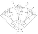
- FIG. 2 is a partially enlarged plan view of the rotor of the electric motor according to the first embodiment.
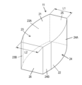
- FIG. 3 is a perspective view of a permanent magnet of the rotor of the first embodiment.
- FIG. 4 is a schematic diagram showing magnetic flux distribution in the electric motor of the first embodiment.
- FIG. 5 is a partially enlarged schematic diagram showing the magnetic flux distribution in the electric motor of the first embodiment.
- FIG. 6 is a partially enlarged plan view of a rotor of an electric motor according to the second embodiment.
- FIG. 7 is a partially enlarged plan view of a rotor of an electric motor according to the third embodiment.
- the electric motor 1 is an inner rotor type motor.
- Fig. 1 is a plan view of the electric motor 1 according to the first embodiment.
- Fig. 2 is a partially enlarged plan view of the rotor 3 of the electric motor 1 according to the first embodiment.
- Fig. 3 is a perspective view of a permanent magnet 11 of the rotor 3 according to the first embodiment.
- the electric motor 1 has a stator 2 and a rotor 3.
- the direction in which the axis 14 (described below) of the rotating shaft 10 (described below) extends is referred to as the axial direction
- the circumferential direction of the rotor 3 is referred to as the circumferential direction C1.
- the case when viewed from the axial direction is referred to as "in a plan view.”
- the direction from a specified position on the electric motor 1 toward the axis is referred to as the "radial inner side.”
- the direction facing away from the axis when viewed from a specified position on the electric motor 1 is referred to as the "radial outer side.”
- the stator 2 is a stator having a stator core 4 and multiple (12 in FIG. 1) coils 5.
- the stator core 4 is a laminated core in which multiple electromagnetic steel sheets are stacked in the thickness direction.
- the stator core 4 has an annular core back 7 and multiple (12 in FIG. 1) teeth 8, and is formed in a generally cylindrical column shape as a whole.
- the multiple teeth 8 are arranged at regular intervals along the circumferential direction C1 on the inner surface of the core back 7, and extend radially inward.
- the multiple coils 5 each correspond to the multiple teeth 8, and each coil 5 is formed by winding a conductor around the corresponding tooth 8.
- the rotor 3 is an IPM (Interior Permanent Magnet) type rotor with permanent magnets embedded inside the rotor core. More specifically, the rotor 3 has a so-called spoke-type rotor structure in which a pair of magnetic pole faces of the magnets are arranged so that they each face in the circumferential direction.
- the rotor 3 is arranged radially inside the stator 2, and includes a rotor core 9, a rotating shaft 10, and multiple (ten in FIG. 1) permanent magnets 11.
- the permanent magnets 11 are members that generate magnetic flux that serves as the driving force for the rotor 3, and are magnetized so that the direction of the magnetic poles is along the circumferential direction C1 of the rotor core 9.
- the electric motor 1 operates as follows. Three-phase currents with a phase difference of 120° electrical angle are supplied to the coils 5 through the power supply connection, exciting the stator 2 and generating a rotating magnetic field. This rotating magnetic field interacts with the magnetic field generated by the permanent magnets 11 provided in the rotor 3, generating a rotational torque in the rotor 3, causing the rotor 3 to rotate around the axis 14.
- the rotor core 9 is a laminated core in which a plurality of electromagnetic steel sheets are laminated in the thickness direction.
- the lamination direction of the plurality of electromagnetic steel sheets is along the axis (hereinafter referred to as the axis direction).
- the rotor core 9 has a circular axial hole 12 and is formed in a cylindrical shape. In the center of the rotor core 9, an axial hole 12 is formed that penetrates the rotor core 9 in the axial direction and opens at both end faces.
- the rotor core 9 has a plurality of outer parts 91 (10 in FIG. 1) and an inner part 92.
- the plurality of outer parts 91 are lined up along the circumferential direction C1, and a magnet arrangement hole 13 is formed between the outer parts 91 adjacent in the circumferential direction C1.
- the inner part 92 is an annular part that connects the radial inner ends of the plurality of outer parts 91, i.e., the parts of each of the plurality of outer parts 91 that are closest to the axis 14.
- a plurality of magnet arrangement holes 13 are formed lined up in the circumferential direction C1.
- the magnet arrangement hole 13 is open on its radially outward side.
- the magnet arrangement hole 13 penetrates in the axial direction, but may have a bottom in the axial direction.
- the rotating shaft 10 is a cylindrical member, and has a shaft center 14 that is the center of rotation.
- the rotating shaft 10 is inserted into a shaft hole 12 of the rotor core 9 and fixed therein.
- Each of the multiple permanent magnets 11 is inserted into a corresponding one of the multiple magnet arrangement holes 13 in the rotor core 9 and fixed using an adhesive or the like.
- a sintered ferrite magnet is used as the permanent magnet 11.
- the permanent magnet 11 may also be a samarium-cobalt permanent magnet, a neodymium magnet, or the like.
- the permanent magnet 11 has approximately the same shape and dimensions as the magnet placement hole 13. Therefore, below, the shape of the permanent magnet 11 will be described in detail, and a description of the shape of the magnet placement hole 13 will be omitted.
- the permanent magnets 11 are roughly rectangular parallelepipeds, and in plan view are shaped like radially elongated spokes (i.e., the longitudinal direction of the permanent magnets 11 is aligned with the radial direction of the rotor 3), and are aligned along the circumferential direction C1.
- the magnetization direction of the permanent magnets 11 is parallel to the circumferential direction C1 of the rotor 3, meaning that two adjacent permanent magnets 11 in the circumferential direction C1 are magnetized so that the two magnetic pole faces facing each other in the circumferential direction C1 are of the same polarity.
- a magnetic pole center line 31 which is an imaginary line that extends radially outward from the axis 14, and the two permanent magnets 11 are arranged symmetrically with respect to the magnetic pole center line 31 in a plan view.
- the permanent magnet 11 has an upper surface 21, a lower surface 22, a first circumferential end face 23 (side face), a second circumferential end face 24 (side face), an outer end face 25 (radially outer end face), and an inner end face 26 (radially inner end face).
- first circumferential end face 23 and the second circumferential end face 24 extend radially
- the outer end face 25 and the inner end face 26 extend in the circumferential direction C1.
- the length of the first circumferential end face 23 and the second circumferential end face 24 is at least twice and at most 20 times the length of the outer end face 25 and the inner end face 26. This allows the area of the rotor core 9 to be used effectively.
- the upper surface 21 and the lower surface 22 are flat surfaces and have the same shape when viewed from above.
- the first circumferential end face 23 and the second circumferential end face 24 are side faces facing the circumferential direction C1 and are also magnetic pole faces.
- the first circumferential end face 23 is a protruding surface that protrudes in the circumferential direction C1 beyond the imaginary plane 32 connecting the inner end and outer end.
- the second circumferential end face 24 is a protruding surface that protrudes in the circumferential direction C1 beyond the imaginary plane 32 connecting the inner end and outer end.
- the first circumferential end face 23 has a first curved surface 23A and a first plane 23B.
- the first curved surface 23A extends from the radially outer side toward the radially inner side.
- the first curved surface 23A is a smooth curved surface that is convex in the circumferential direction C1, and is curved in a plan view.
- the first plane 23B is disposed radially inside the first curved surface 23A.
- the first plane 23B is a plane that is straight in a plan view.
- the first plane 23B is parallel to the magnetic pole center line 31 in a plan view.
- the circumferential width of the radially inner part of the permanent magnet 11, i.e., the part closer to the axis 14 than the center of the permanent magnet 11, can be secured to be wide.
- the radial length of the first plane 23B is 50% or less of the radial length of the entire first circumferential end face 23.
- the second circumferential end face 24 has a second curved surface 24A and a second plane surface 24B.
- the second curved surface 24A extends from the radially outer side toward the radially inner side.
- the second curved surface 24A is a smooth curved surface that is convex in the circumferential direction C1, and is curved in a plan view.
- the second plane surface 24B is disposed radially inward of the second curved surface 24A.
- the second plane surface 24B is a flat surface that is straight in a plan view.
- the second plane surface 24B is parallel to the magnetic pole center line 31 in a plan view.
- the outer end surface 25 is flat and is located radially outward of the permanent magnet 11.
- the outer end surface 25 extends generally along the circumferential direction C1 in a plan view.
- the inner end surface 26 is flat and is located radially inward of the permanent magnet 11.
- the inner end surface 26 extends generally along the circumferential direction C1 in a plan view.
- the circumferential length L1 of the outer end face 25 is shorter than the circumferential length L2 of the inner end face 26. Specifically, the circumferential length L1 of the outer end face 25 is in the range of 60 to 80% of the circumferential length L2 of the inner end face 26.
- the normals of the first circumferential end face 23 and the second circumferential end face 24 face further radially outward. As a result, the magnetic flux emanating from the first curved surface 23A of the first circumferential end face 23 and the second curved surface 24A of the second circumferential end face 24 tends to face radially outward, that is, toward the stator 2. Therefore, the torque of the electric motor 1 can be further improved.
- the rotor core 9 has two holes 41, 42 between two permanent magnets 11 adjacent to each other in the circumferential direction C1.
- Each of the two holes 41, 42 is a through hole extending along the axial direction of the rotating shaft 10.
- the two holes 41, 42 are provided on the outer periphery of the rotor core 9.
- the holes 41, 42 are aligned along the circumferential direction C1.
- the holes 41, 42 are significantly smaller than, for example, the magnet arrangement hole 13.
- the total area of the two holes 41, 42 is 20% or less of the area of one magnet arrangement hole 13.
- the two holes 41, 42 are provided symmetrically with respect to the magnetic pole center line 31.
- the holes 41, 42 are each circular in a plan view.
- FIG. 4 is a schematic diagram showing the magnetic flux distribution in the electric motor 1 of the first embodiment.
- Figure 5 is a partially enlarged schematic diagram showing the magnetic flux distribution in the electric motor 1 of the first embodiment.
- Magnetic field lines M extend from the permanent magnet 11 and extend radially outward from the permanent magnet 11. The magnetic field lines M then branch off to avoid holes 41 and 42, which have a larger magnetic resistance than the surrounding areas. In other words, the magnetic field lines M branch off into three locations: between the holes 41 and 42, between the permanent magnet 11 and the hole 41, and between the permanent magnet 11 and the hole 42, and use each of these as a path.
- the magnetic flux path formed by the two holes 41, 42 is symmetrical with respect to the magnetic pole center line 31, which further reduces torque ripple.
- the two holes 41, 42 are provided at positions where the magnetic flux density between the two holes 41, 42 at no load is ⁇ 40% or less of the magnetic flux density between the permanent magnet 11 and the hole closest to the permanent magnet 11 at no load. Therefore, the difference in magnetic flux density in the multiple magnetic flux paths is reduced, thereby reducing torque ripple.
- the distance between the holes 41, 42 may be ⁇ 85% of the distance between the permanent magnet 11 and the hole 41 or hole 42.
- the two holes 41, 42 are provided on the outer periphery of the rotor core 9, i.e., in an area within the rotor core 9 that is farther from the center of the rotor core 9 when viewed from the axis 14. In this way, since multiple holes 41, 42 are provided at positions away from the axis 14, the flow of magnetic flux near the stator 2 can be adjusted, and therefore torque ripple can be reduced.
- the two holes 41, 42 are located near the outer periphery of the rotor core 9, so the above effect is high.
- multiple holes 41, 42 penetrate in the axial direction, which increases the effect of making the magnetic resistance different from the surroundings, thereby contributing to reducing torque ripple.
- the rotor core may be a dust core whose main component is a dust material obtained by compressing a powdered magnetic body.
- the side surface of the permanent magnet may consist of curved surfaces only.
- the two sides of the permanent magnet may have different shapes.
- the magnets may be bonded magnets made by mixing and kneading magnet powder, which is a hard magnetic material, with a binder such as resin or rubber and molding it, or they may be sintered magnets made by baking magnet powder at high temperature.
- Fig. 6 is a partially enlarged plan view of the rotor 3 of the electric motor 1 according to the second embodiment. Note that the basic configuration and operation of the electric motor 1 according to the second embodiment are similar to those of the electric motor 1 according to the first embodiment, and therefore the following description will focus on the differences.
- the outer portion 91 of the rotor core 9 has two holes 41A, 42A between two adjacent permanent magnets 11 in the circumferential direction C1.
- Each of the two holes 41A, 42A is a through hole extending along the axial direction of the rotating shaft 10.
- the two holes 41A, 42A are provided on the outer periphery of the rotor core 9.
- the holes 41A, 42A are aligned along the circumferential direction C1.
- the holes 41A, 42A are significantly smaller than, for example, the magnet arrangement hole 13.
- the two holes 41A, 42A are provided symmetrically with respect to the magnetic pole center line 31.
- the holes 41A, 42A are each elliptical in plan view. Specifically, the major axes of the holes 41A, 42A are generally along the radial direction, and the minor axes are generally along the circumferential direction C1.
- the two holes 41A, 42A are located at positions where the magnetic flux density between the two holes 41A, 42A when no load is applied is less than ⁇ 40% of the magnetic flux density between the permanent magnet 11 and the hole closest to the permanent magnet 11 when no load is applied. Therefore, the difference in magnetic flux density between the multiple magnetic flux paths is reduced, and therefore torque ripple is reduced.
- the two holes 41A, 42A are provided on the outer periphery of the rotor core 9, i.e., in an area within the rotor core 9 that is farther from the center of the rotor core 9 when viewed from the axis 14. In this way, since multiple holes 41A, 42A are provided at positions away from the axis 14, the flow of magnetic flux near the stator 2 can be adjusted, and therefore torque ripple can be reduced.
- the two holes 41A, 42A are located near the outer periphery of the rotor core 9, so the above effect is high.
- Fig. 7 is a partially enlarged plan view of the rotor 3 of the electric motor 1 according to the third embodiment. Note that the basic configuration and operation of the electric motor 1 according to the third embodiment are similar to those of the electric motor 1 according to the first embodiment, and therefore the following description will focus on the differences.
- the outer portion 91 of the rotor core 9 has four holes 41B, 42B, 43B, and 44B between two adjacent permanent magnets 11 in the circumferential direction C1.
- the four holes 41B, 42B, 43B, and 44B are through holes extending along the axial direction of the rotating shaft 10.
- the four holes 41B, 42B, 43B, and 44B are provided on the outer periphery of the rotor core 9.
- Each of the holes 41B, 42B, 43B, and 44B is aligned along the circumferential direction C1.
- the holes 41B and 42B are significantly smaller than, for example, the magnet arrangement hole 13.
- the pair of holes 41B and 42B and the pair of holes 43B and 44B are provided symmetrically with respect to the magnetic pole center line 31.
- the holes 41B, 42B, 43B, and 44B are each circular in a plan view.
- the four holes 41B, 42B, 43B, and 44B are positioned so that the magnetic flux density between the four holes 41B, 42B, 43B, and 44B when no load is applied is within ⁇ 40% of the magnetic flux density between the permanent magnet 11 and the hole closest to the permanent magnet 11 when no load is applied. Therefore, the difference in magnetic flux density between the multiple magnetic flux paths is reduced, and torque ripple is therefore reduced.
- the four holes 41B, 42B, 43B, 44B are provided on the outer periphery of the rotor core 9, i.e., in an area within the rotor core 9 that is farther from the center of the rotor core 9 when viewed from the axis 14. In this way, since multiple holes 41B, 42B, 43B, 44B are provided at positions away from the axis 14, the flow of magnetic flux near the stator 2 can be adjusted, and therefore torque ripple can be reduced.
- the four holes 41B, 42B, 43B, 44B are located near the outer periphery of the rotor core 9, so the above effect is high.
- the number of holes may be three or may be five or more.
- the holes do not need to penetrate the rotor core 9.
- the shape of the hole is not limited to the first to third embodiments.
- the hole may be polygonal, or may have a shape obtained by combining curved and straight lines.
- the multiple holes are preferably arranged in a circumferential direction, but may be provided at different radial positions.
- the multiple holes do not have to all be the same shape or size, and may include holes of different shapes and sizes.
- the rotor (3) of the first aspect comprises a rotor core (9), a plurality of permanent magnets (11), and a rotating shaft.
- the rotor core (9) has a plurality of magnet arrangement holes (13) arranged in the circumferential direction (C1).
- the plurality of permanent magnets (11) are respectively arranged in the plurality of magnet arrangement holes (13).
- the rotating shaft is fixed to the rotor core (9) and has a center of rotation about the axis (14).
- Each of the plurality of permanent magnets (11) has an inner end face (26), an outer end face (25), and a pair of side faces (23, 24).
- the inner end face (26) faces the axis (14) of the rotating shaft (10) in a plane having a normal line coinciding with the axis (14) of the rotating shaft (10).
- the outer end face (25) faces in the opposite direction to the axis (14) of the rotating shaft (10) in a plane having a normal line coinciding with the axis (14) of the rotating shaft (10).
- the pair of side faces (23, 24) protrude in the circumferential direction from an imaginary plane (32) that connects the circumferential edge of the inner end face (26) and the circumferential edge of the outer end face (25).
- the pair of side faces (23, 24) are magnetic pole faces, and the magnetic pole faces of the same polarity of two permanent magnets (11) adjacent in the circumferential direction (C1) among the multiple permanent magnets (11) are arranged facing each other in the circumferential direction (C1).
- the circumferential length (L1) of the outer end face (25) is shorter than the circumferential length (L2) of the inner end face (26).
- the rotor core (9) has multiple holes (41, 42, 41A, 42A, 41B, 42B, 43B, 44B) between adjacent permanent magnets in the circumferential direction (C1) of the multiple permanent magnets (11).
- the pair of side surfaces (23, 24) protrude outward in the circumferential direction, the effective area of the magnetic pole face of the permanent magnet (11) is increased, and the amount of magnetic flux is increased, and therefore the average torque of the electric motor (1) is increased. Furthermore, the further outward in the radial direction, the more the normal line of the pair of side surfaces (23, 24) faces radially outward. As a result, the magnetic flux coming from the part of the pair of side surfaces (23, 24) opposite the axis (14) is likely to face the opposite side to the axis (14). Therefore, the torque of the electric motor (1) can be further improved. Furthermore, by providing multiple holes (41, 42, 41A, 42A, 41B, 42B, 43B, 44B), the location where the magnetic flux flows can be adjusted. As a result of the above, the torque ripple can be reduced while maintaining the average torque.
- the multiple holes (41, 42, 41A, 42A, 41B, 42B, 43B, 44B) are arranged symmetrically with respect to the magnetic pole center line (31) between the circumferentially adjacent permanent magnets of the multiple permanent magnets (11).
- the magnetic flux path formed by the multiple holes (41, 42, 41A, 42A, 41B, 42B, 43B, 44B) is symmetrical with respect to the magnetic pole center line (31), thereby reducing torque ripple.
- the multiple holes are provided at positions where the magnetic flux density at no load between the multiple holes (41, 42, 41A, 42A, 41B, 42B, 43B, 44B) is ⁇ 40% or less of the magnetic flux density at no load between one of the multiple permanent magnets (11) and the hole closest to the permanent magnet (11).
- the difference in magnetic flux density in the magnetic flux path formed by the multiple holes is reduced, thereby reducing torque ripple.
- the multiple holes are provided in an area of the rotor core (9) farther from the center of the rotor core (9) when viewed from the shaft center (14).
- multiple holes are provided at positions away from the axis, so that the flow of magnetic flux near the stator (2) can be adjusted, thereby reducing torque ripple.
- the holes (41, 42, 41A, 42A, 41B, 42B, 43B, 44B) are through holes extending along the axial direction of the rotating shaft (10).
- multiple holes penetrate in the axial direction, which increases the effect of making the magnetic resistance different from the surroundings, thereby reducing torque ripple.
- each of the pair of side surfaces (23, 24) has a curved surface or a combination of a curved surface and a flat surface.
- the volume of the permanent magnet (11) and the orientation of the side surfaces can be appropriately set by adjusting the shape of a pair of side surfaces, and as a result, torque ripple can be reduced while maintaining the average torque.
- each of the pair of side surfaces (23, 24) has a curved surface (23A, 24A) that is convex outward in the circumferential direction, and a flat surface (23B, 24B) that is disposed on the axial center (14) side of the curved surface (23A, 24A).
- each of the pair of side surfaces (23, 24) has a flat surface (23B, 24B), the portions of the side surfaces (23, 24) facing the axis (14) can be brought closer to each other in the circumferential direction (C1), thereby increasing the volume of the permanent magnet (11).
- the planes (23B, 24B) are parallel to the magnetic pole center line (31) between the multiple permanent magnets (11) when viewed along the axial direction of the rotating shaft (10).
- the planes (23B, 24B) of the pair of side surfaces (23, 24) are parallel to the magnetic pole center line (31), so that the portions of the side surfaces (23, 24) on the axis (14) side can be brought closer to each other in the circumferential direction (C1), thereby increasing the volume of the permanent magnet (11).
- the electric motor (1) according to the ninth aspect includes a rotor (3) according to any one of the first to eighth aspects and a stator (2).
- This embodiment allows torque ripple to be reduced while maintaining average torque.
- the rotor and motor disclosed herein can reduce torque ripple while maintaining average torque. Therefore, the rotor and motor disclosed herein are industrially useful.
Abstract
Provided are a rotor and a motor which are capable of reducing torque ripples while maintaining an average torque. In this rotor (3), a first circumferential end surface (23) and a second circumferential end surface (24) of each of a plurality of permanent magnets (11) protrude in the circumferential direction from a virtual plane (32) which connects the circumferential edge of an inner end surface (26) and the circumferential edge of an outer end surface (25). The first circumferential end surface (23) and the second circumferential end surface (24) are magnetic pole surfaces, and magnetic pole surfaces of the same pole of two permanent magnets (11), which are adjacent to each other in a circumferential direction (C1) among the plurality of permanent magnets (11), are disposed to face each other in the circumferential direction (C1). The circumferential length (L1) of the outer end surface (25) is shorter than the circumferential length (L2) of the inner end surface (26). In a rotor core (9), a plurality of holes (41), (42) are provided between the permanent magnets which are adjacent to each other in the circumferential direction (C1) of the plurality of permanent magnets (11).
Description
本開示は、回転子及び電動機に関し、特に、複数の永久磁石を備える回転子、及び回転子を備える電動機に関する。
The present disclosure relates to rotors and electric motors, and in particular to rotors having multiple permanent magnets and electric motors having rotors.
特許文献1には、回転子鉄心と、回転子鉄心の内部に埋め込まれた複数の永久磁石とを有する回転子が開示されている。永久磁石の一対の周方向端面の一方又は他方は、その端面の内端と外端を結ぶ平面よりも周方向に突出している。また、回転子鉄心において、永久磁石同士の間には軸方向に貫通する1個の大きな貫通孔が設けられている。
Patent Document 1 discloses a rotor having a rotor core and multiple permanent magnets embedded inside the rotor core. One or the other of a pair of circumferential end faces of the permanent magnets protrudes in the circumferential direction beyond a plane connecting the inner and outer ends of the end faces. In addition, the rotor core has one large through hole that penetrates in the axial direction between the permanent magnets.
特許文献1に記載の回転子では、永久磁石の一対の周方向端面の一方又は両方がその端面の内端と外端を結ぶ平面よりも周方向に突出しているので、永久磁石の体積が増加している。したがって、回転子における磁束密度が高くなり、その結果、電動機の平均トルクが大きくなる。しかし、特許文献1では、振動や騒音の原因となるトルクリップルの解消については着目も提案もされていない。
In the rotor described in Patent Document 1, one or both of a pair of circumferential end faces of the permanent magnet protrude circumferentially beyond the plane connecting the inner and outer ends of the end faces, increasing the volume of the permanent magnet. This increases the magnetic flux density in the rotor, and as a result, the average torque of the motor increases. However, Patent Document 1 does not address or suggest how to eliminate torque ripple, which causes vibration and noise.
本開示は上記の点に鑑みてなされたものであり、平均トルクを維持しつつトルクリップルを低減可能な回転子及び電動機を提供することを目的とする。
This disclosure has been made in consideration of the above points, and aims to provide a rotor and an electric motor that can reduce torque ripple while maintaining average torque.
本開示の一態様に係る回転子は、回転子鉄心と、複数の永久磁石と、回転軸と、を備えている。前記回転子鉄心は、周方向に並んだ複数の磁石配置穴を有する。前記複数の永久磁石は、前記複数の磁石配置穴にそれぞれ配置されている。前記回転軸は、前記回転子鉄心に固定され、軸心を回転中心とする。前記複数の永久磁石の各々は、内側端面と、外側端面と、一対の側面とを有している。前記内側端面は、前記回転軸の前記軸心に面する。前記外側端面は、前記回転軸の前記軸心とは反対向きに面する。前記一対の側面は、前記内側端面の周方向縁と前記外側端面の周方向縁をそれぞれ結ぶ仮想平面より周方向に突出している。前記一対の側面が磁極面であり、前記複数の永久磁石のうち周方向に隣接する2個の永久磁石の同極の磁極面同士が周方向に対向して配置されている。前記外側端面の周方向長さは、前記内側端面の周方向長さより短い。前記回転子鉄心には、前記複数の永久磁石の周方向間に複数の穴が設けられている。
The rotor according to one embodiment of the present disclosure includes a rotor core, a plurality of permanent magnets, and a rotating shaft. The rotor core has a plurality of magnet arrangement holes arranged in a circumferential direction. The plurality of permanent magnets are arranged in the plurality of magnet arrangement holes. The rotating shaft is fixed to the rotor core and has a center of rotation at the axis. Each of the plurality of permanent magnets has an inner end face, an outer end face, and a pair of side faces. The inner end face faces the axis of the rotating shaft. The outer end face faces in the opposite direction to the axis of the rotating shaft. The pair of side faces protrude in the circumferential direction from an imaginary plane that connects the circumferential edge of the inner end face and the circumferential edge of the outer end face. The pair of side faces are magnetic pole faces, and the magnetic pole faces of the same polarity of two circumferentially adjacent permanent magnets among the plurality of permanent magnets are arranged to face each other in the circumferential direction. The circumferential length of the outer end face is shorter than the circumferential length of the inner end face. The rotor core has a plurality of holes between the circumferential directions of the plurality of permanent magnets.
本開示の一態様に係る電動機は、前記回転子と固定子とを備えている。
The electric motor according to one embodiment of the present disclosure includes the rotor and the stator.
本開示の一態様に係る回転子及び電動機によれば、平均トルクを維持しつつトルクリップルを低減できる。
The rotor and motor according to one embodiment of the present disclosure can reduce torque ripple while maintaining average torque.
(実施形態)
以下、本開示の実施形態に係る回転子及び電動機について図面を参照して詳細に説明する。ただし、下記の実施形態において説明する各図は模式的な図であり、各構成要素の大きさ及び厚さのそれぞれの比が必ずしも実際の寸法比を反映しているとは限らない。なお、以下の実施形態で説明する構成は本開示の一例に過ぎない。本開示は、以下の実施形態に限定されず、本開示の効果を奏することができれば、設計等に応じて種々の変更が可能である。 (Embodiment)
Hereinafter, the rotor and the electric motor according to the embodiment of the present disclosure will be described in detail with reference to the drawings. However, each figure described in the following embodiment is a schematic diagram, and the ratio of the size and thickness of each component does not necessarily reflect the actual dimensional ratio. Note that the configuration described in the following embodiment is merely one example of the present disclosure. The present disclosure is not limited to the following embodiment, and various modifications are possible depending on the design, etc., as long as the effects of the present disclosure can be achieved.
(第1実施形態)
(1)電動機の概要
図1~図3を用いて、本開示の第1実施形態に係る電動機1を説明する。電動機1は、インナーロータタイプのモータである。図1は、第1実施形態に係る電動機1の平面図である。図2は、第1実施形態に係る電動機1の回転子3の部分拡大平面図である。図3は、第1実施形態に係る回転子3の永久磁石11の斜視図である。 First Embodiment
(1) Overview of the Electric Motor Anelectric motor 1 according to a first embodiment of the present disclosure will be described with reference to Figs. 1 to 3. The electric motor 1 is an inner rotor type motor. Fig. 1 is a plan view of the electric motor 1 according to the first embodiment. Fig. 2 is a partially enlarged plan view of the rotor 3 of the electric motor 1 according to the first embodiment. Fig. 3 is a perspective view of a permanent magnet 11 of the rotor 3 according to the first embodiment.
(1)電動機の概要
図1~図3を用いて、本開示の第1実施形態に係る電動機1を説明する。電動機1は、インナーロータタイプのモータである。図1は、第1実施形態に係る電動機1の平面図である。図2は、第1実施形態に係る電動機1の回転子3の部分拡大平面図である。図3は、第1実施形態に係る回転子3の永久磁石11の斜視図である。 First Embodiment
(1) Overview of the Electric Motor An
図1に示すように、電動機1は、固定子2と、回転子3とを有している。なお、これ以降の説明において、回転軸10(後述)の軸心14(後述)が延びる方向を軸心方向とし、回転子3の周方向を周方向C1と表現する。また、軸心方向から見る場合を、「平面視において」と表現する。また、電動機1における所定の位置から軸心へ向かう方向を「径方向内側」と表現する。電動機1における所定の位置からみて軸心とは逆へ向かう方向を「径方向外側」と表現する。
As shown in FIG. 1, the electric motor 1 has a stator 2 and a rotor 3. In the following explanation, the direction in which the axis 14 (described below) of the rotating shaft 10 (described below) extends is referred to as the axial direction, and the circumferential direction of the rotor 3 is referred to as the circumferential direction C1. The case when viewed from the axial direction is referred to as "in a plan view." The direction from a specified position on the electric motor 1 toward the axis is referred to as the "radial inner side." The direction facing away from the axis when viewed from a specified position on the electric motor 1 is referred to as the "radial outer side."
固定子2は、固定子鉄心4と、複数(図1では12個)のコイル5と、を有するステータである。固定子鉄心4は、複数の電磁鋼板が厚さ方向に積層された積層コアである。固定子鉄心4は、円環状のコアバック7と、複数(図1では12個)のティース8とを有しており、全体として略円筒柱状に形成されている。複数のティース8は、コアバック7の内周面に周方向C1に沿って一定間隔で配置されており、径方向内側に延びている。複数のコイル5は、それぞれ複数のティース8に対応し、各コイル5は、対応するティース8に導体が巻かれることによって形成されている。
The stator 2 is a stator having a stator core 4 and multiple (12 in FIG. 1) coils 5. The stator core 4 is a laminated core in which multiple electromagnetic steel sheets are stacked in the thickness direction. The stator core 4 has an annular core back 7 and multiple (12 in FIG. 1) teeth 8, and is formed in a generally cylindrical column shape as a whole. The multiple teeth 8 are arranged at regular intervals along the circumferential direction C1 on the inner surface of the core back 7, and extend radially inward. The multiple coils 5 each correspond to the multiple teeth 8, and each coil 5 is formed by winding a conductor around the corresponding tooth 8.
回転子3は、回転子鉄心の内部に永久磁石が埋め込まれたIPM(Interior Permanent Magnet)タイプのロータである。さらに具体的には、回転子3は、磁石の一対の磁極面がそれぞれ周方向を向くように配置された、いわゆるスポーク型のロータ構造を有している。回転子3は、固定子2の径方向内側に配置され、回転子鉄心9と、回転軸10と、複数(図1では10個)の永久磁石11とを備えている。永久磁石11は、回転子3の駆動力となる磁束を発生する部材であり、磁極の方向が回転子鉄心9の周方向C1に沿うように着磁されている。
The rotor 3 is an IPM (Interior Permanent Magnet) type rotor with permanent magnets embedded inside the rotor core. More specifically, the rotor 3 has a so-called spoke-type rotor structure in which a pair of magnetic pole faces of the magnets are arranged so that they each face in the circumferential direction. The rotor 3 is arranged radially inside the stator 2, and includes a rotor core 9, a rotating shaft 10, and multiple (ten in FIG. 1) permanent magnets 11. The permanent magnets 11 are members that generate magnetic flux that serves as the driving force for the rotor 3, and are magnetized so that the direction of the magnetic poles is along the circumferential direction C1 of the rotor core 9.
電動機1は、以下のように動作する。電源接続部を通じて、互いに電気角で120°の位相差を有する3相の電流がそれぞれ複数のコイル5に供給されて固定子2が励磁され、回転磁界が発生する。この回転磁界と、回転子3に設けられた永久磁石11が発生する磁界とが相互作用して、回転子3に回転トルクが発生し、その結果、回転子3が軸心14回りに回転する。
The electric motor 1 operates as follows. Three-phase currents with a phase difference of 120° electrical angle are supplied to the coils 5 through the power supply connection, exciting the stator 2 and generating a rotating magnetic field. This rotating magnetic field interacts with the magnetic field generated by the permanent magnets 11 provided in the rotor 3, generating a rotational torque in the rotor 3, causing the rotor 3 to rotate around the axis 14.
(2)回転子
回転子3の構成及び機能を説明する。 (2) Rotor The configuration and function of therotor 3 will be described.
回転子3の構成及び機能を説明する。 (2) Rotor The configuration and function of the
(2-1)回転子鉄心
回転子鉄心9は、複数の電磁鋼板)が厚さ方向に積層された積層コアである。複数の電磁鋼板の積層方向は、軸心に沿う方向(以下、軸心方向という)である。回転子鉄心9は、円形の軸孔12を有しており、円筒形状に形成されている。回転子鉄心9の中心には、回転子鉄心9を軸心方向に貫通し、両端面でそれぞれ開口する軸孔12が形成されている。回転子鉄心9は、複数(図1では10個)のアウター部91と、インナー部92とを有している。複数のアウター部91は、周方向C1に沿って並んでおり、周方向C1において隣接するアウター部91間に磁石配置穴13を形成している。インナー部92は、複数のアウター部91の径方向内側端すなわち複数のアウター部91のそれぞれにおける軸心14に最も近い部分を連結する環状部分である。上記の構成により、周方向C1に並んだ複数の磁石配置穴13が形成されている。この実施形態では、磁石配置穴13は、その径方向外側が開口している。また、磁石配置穴13は軸心方向に貫通しているが、軸心方向に底部を有していてもよい。 (2-1) Rotor Core Therotor core 9 is a laminated core in which a plurality of electromagnetic steel sheets are laminated in the thickness direction. The lamination direction of the plurality of electromagnetic steel sheets is along the axis (hereinafter referred to as the axis direction). The rotor core 9 has a circular axial hole 12 and is formed in a cylindrical shape. In the center of the rotor core 9, an axial hole 12 is formed that penetrates the rotor core 9 in the axial direction and opens at both end faces. The rotor core 9 has a plurality of outer parts 91 (10 in FIG. 1) and an inner part 92. The plurality of outer parts 91 are lined up along the circumferential direction C1, and a magnet arrangement hole 13 is formed between the outer parts 91 adjacent in the circumferential direction C1. The inner part 92 is an annular part that connects the radial inner ends of the plurality of outer parts 91, i.e., the parts of each of the plurality of outer parts 91 that are closest to the axis 14. With the above configuration, a plurality of magnet arrangement holes 13 are formed lined up in the circumferential direction C1. In this embodiment, the magnet arrangement hole 13 is open on its radially outward side. Also, the magnet arrangement hole 13 penetrates in the axial direction, but may have a bottom in the axial direction.
回転子鉄心9は、複数の電磁鋼板)が厚さ方向に積層された積層コアである。複数の電磁鋼板の積層方向は、軸心に沿う方向(以下、軸心方向という)である。回転子鉄心9は、円形の軸孔12を有しており、円筒形状に形成されている。回転子鉄心9の中心には、回転子鉄心9を軸心方向に貫通し、両端面でそれぞれ開口する軸孔12が形成されている。回転子鉄心9は、複数(図1では10個)のアウター部91と、インナー部92とを有している。複数のアウター部91は、周方向C1に沿って並んでおり、周方向C1において隣接するアウター部91間に磁石配置穴13を形成している。インナー部92は、複数のアウター部91の径方向内側端すなわち複数のアウター部91のそれぞれにおける軸心14に最も近い部分を連結する環状部分である。上記の構成により、周方向C1に並んだ複数の磁石配置穴13が形成されている。この実施形態では、磁石配置穴13は、その径方向外側が開口している。また、磁石配置穴13は軸心方向に貫通しているが、軸心方向に底部を有していてもよい。 (2-1) Rotor Core The
(2-2)回転軸
回転軸10は、円柱状の部材であり、回転中心となる軸心14を有している。回転軸10は、回転子鉄心9の軸孔12に挿入され、固定されている。 (2-2) Rotating Shaft The rotatingshaft 10 is a cylindrical member, and has a shaft center 14 that is the center of rotation. The rotating shaft 10 is inserted into a shaft hole 12 of the rotor core 9 and fixed therein.
回転軸10は、円柱状の部材であり、回転中心となる軸心14を有している。回転軸10は、回転子鉄心9の軸孔12に挿入され、固定されている。 (2-2) Rotating Shaft The rotating
(2-3)永久磁石
複数の永久磁石11は、各々、回転子鉄心9の複数の磁石配置穴13のうちの対応する磁石配置穴13に挿入され接着剤等を用いて固定されている。永久磁石11は、フェライト焼結磁石が用いられる。永久磁石11は、サマリウム・コバルト系の永久磁石、ネオジム磁石等であってもよい。 (2-3) Permanent Magnets Each of the multiplepermanent magnets 11 is inserted into a corresponding one of the multiple magnet arrangement holes 13 in the rotor core 9 and fixed using an adhesive or the like. A sintered ferrite magnet is used as the permanent magnet 11. The permanent magnet 11 may also be a samarium-cobalt permanent magnet, a neodymium magnet, or the like.
複数の永久磁石11は、各々、回転子鉄心9の複数の磁石配置穴13のうちの対応する磁石配置穴13に挿入され接着剤等を用いて固定されている。永久磁石11は、フェライト焼結磁石が用いられる。永久磁石11は、サマリウム・コバルト系の永久磁石、ネオジム磁石等であってもよい。 (2-3) Permanent Magnets Each of the multiple
永久磁石11は、磁石配置穴13と略同じ形状及び寸法である。したがって、以下、永久磁石11の形状を詳細に説明し、磁石配置穴13の形状の説明は省略される。
The permanent magnet 11 has approximately the same shape and dimensions as the magnet placement hole 13. Therefore, below, the shape of the permanent magnet 11 will be described in detail, and a description of the shape of the magnet placement hole 13 will be omitted.
永久磁石11は、概ね直方体形状であり、平面視において径方向に長いスポーク形状であり(つまり、永久磁石11の長手方向は回転子3の径方向に沿っており)、周方向C1に沿って並んでいる。
The permanent magnets 11 are roughly rectangular parallelepipeds, and in plan view are shaped like radially elongated spokes (i.e., the longitudinal direction of the permanent magnets 11 is aligned with the radial direction of the rotor 3), and are aligned along the circumferential direction C1.
永久磁石11の磁化方向は、回転子3の周方向C1と平行であり、つまり周方向C1に隣り合う2個の永久磁石11は、周方向C1において互いに向き合う2つの磁極面が同極となるように着磁されている。なお、2個の永久磁石11の間には、図2に示すように、軸心14から径方向外側に延びる仮想線である磁極中心線31が存在しており、2個の永久磁石11は、平面視において、磁極中心線31に対して線対称に配置されている。
The magnetization direction of the permanent magnets 11 is parallel to the circumferential direction C1 of the rotor 3, meaning that two adjacent permanent magnets 11 in the circumferential direction C1 are magnetized so that the two magnetic pole faces facing each other in the circumferential direction C1 are of the same polarity. As shown in FIG. 2, between the two permanent magnets 11, there is a magnetic pole center line 31, which is an imaginary line that extends radially outward from the axis 14, and the two permanent magnets 11 are arranged symmetrically with respect to the magnetic pole center line 31 in a plan view.
図2及び図3に示すように、永久磁石11は、上面21と、下面22と、第1周方向端面23(側面)と、第2周方向端面24(側面)と、外側端面25(径方向外側端面)と、内側端面26(径方向内側端面)と、を有している。平面視において、第1周方向端面23及び第2周方向端面24は径方向に延びており、外側端面25及び内側端面26は周方向C1に延びている。第1周方向端面23及び第2周方向端面24の長さは、外側端面25及び内側端面26の長さの2倍以上、20倍以下である。これにより、回転子鉄心9の領域を有効に利用することができる。
As shown in Figures 2 and 3, the permanent magnet 11 has an upper surface 21, a lower surface 22, a first circumferential end face 23 (side face), a second circumferential end face 24 (side face), an outer end face 25 (radially outer end face), and an inner end face 26 (radially inner end face). In a plan view, the first circumferential end face 23 and the second circumferential end face 24 extend radially, and the outer end face 25 and the inner end face 26 extend in the circumferential direction C1. The length of the first circumferential end face 23 and the second circumferential end face 24 is at least twice and at most 20 times the length of the outer end face 25 and the inner end face 26. This allows the area of the rotor core 9 to be used effectively.
上面21及び下面22は、平面であり、平面視において同形である。
The upper surface 21 and the lower surface 22 are flat surfaces and have the same shape when viewed from above.
第1周方向端面23及び第2周方向端面24は、周方向C1に向く側面であり、磁極面でもある。
The first circumferential end face 23 and the second circumferential end face 24 are side faces facing the circumferential direction C1 and are also magnetic pole faces.
第1周方向端面23は、その内端と外端とを繋ぐ仮想平面32よりも周方向C1に突出している突出面である。第2周方向端面24は、その内端と外端とを繋ぐ仮想平面32よりも周方向C1に突出している突出面である。上記構造によって、永久磁石11の磁極面の有効面積が大きくなることで、磁束量は大きくなり、したがって電動機1の平均トルクが高くなる。
The first circumferential end face 23 is a protruding surface that protrudes in the circumferential direction C1 beyond the imaginary plane 32 connecting the inner end and outer end. The second circumferential end face 24 is a protruding surface that protrudes in the circumferential direction C1 beyond the imaginary plane 32 connecting the inner end and outer end. With the above structure, the effective area of the magnetic pole face of the permanent magnet 11 is increased, thereby increasing the amount of magnetic flux and therefore increasing the average torque of the electric motor 1.
第1周方向端面23は、第1曲面23Aと、第1平面23Bとを有している。第1曲面23Aは、径方向外側から径方向内側に向かって延びている。第1曲面23Aは、周方向C1に凸となる滑らかな曲面であり、平面視において曲線となっている。第1平面23Bは、第1曲面23Aの径方向内側に配置されている。第1平面23Bは、平面であり、平面視において直線となっている。第1平面23Bは、平面視において、磁極中心線31に対して平行である。上記の構成により、永久磁石11の径方向内側部分すなわち永久磁石11の中央より軸心14に近い部分の周方向幅を広く確保できる。なお、第1平面23Bの径方向長さは、第1周方向端面23全体の径方向長さの50%以下である。
The first circumferential end face 23 has a first curved surface 23A and a first plane 23B. The first curved surface 23A extends from the radially outer side toward the radially inner side. The first curved surface 23A is a smooth curved surface that is convex in the circumferential direction C1, and is curved in a plan view. The first plane 23B is disposed radially inside the first curved surface 23A. The first plane 23B is a plane that is straight in a plan view. The first plane 23B is parallel to the magnetic pole center line 31 in a plan view. With the above configuration, the circumferential width of the radially inner part of the permanent magnet 11, i.e., the part closer to the axis 14 than the center of the permanent magnet 11, can be secured to be wide. The radial length of the first plane 23B is 50% or less of the radial length of the entire first circumferential end face 23.
第2周方向端面24は、第2曲面24Aと、第2平面24Bとを有している。第2曲面24Aは、径方向外側から径方向内側に向かって延びている。第2曲面24Aは、周方向C1に凸となる滑らかな曲面であり、平面視において曲線となっている。第2平面24Bは、第2曲面24Aの径方向内側に配置されている。第2平面24Bは、平面であり、平面視において直線となっている。第2平面24Bは、平面視において、磁極中心線31に対して平行である。上記の構成により、永久磁石11の径方向内側部分の周方向幅を広く確保できる。なお、第2平面24Bの径方向長さは、第2周方向端面24全体の径方向長さの50%以下である。
The second circumferential end face 24 has a second curved surface 24A and a second plane surface 24B. The second curved surface 24A extends from the radially outer side toward the radially inner side. The second curved surface 24A is a smooth curved surface that is convex in the circumferential direction C1, and is curved in a plan view. The second plane surface 24B is disposed radially inward of the second curved surface 24A. The second plane surface 24B is a flat surface that is straight in a plan view. The second plane surface 24B is parallel to the magnetic pole center line 31 in a plan view. With the above configuration, the circumferential width of the radially inner portion of the permanent magnet 11 can be secured widely. The radial length of the second plane surface 24B is 50% or less of the radial length of the entire second circumferential end face 24.
外側端面25は、平面であり、永久磁石11の径方向外側にある。外側端面25は、平面視において概ね周方向C1に沿って延びている。
The outer end surface 25 is flat and is located radially outward of the permanent magnet 11. The outer end surface 25 extends generally along the circumferential direction C1 in a plan view.
内側端面26は、平面であり、永久磁石11の径方向内側にある。内側端面26は、平面視において概ね周方向C1に沿って延びている。
The inner end surface 26 is flat and is located radially inward of the permanent magnet 11. The inner end surface 26 extends generally along the circumferential direction C1 in a plan view.
外側端面25の周方向長さL1は、内側端面26の周方向長さL2より短い。具体的には、外側端面25の周方向長さL1は、内側端面26の周方向長さL2の60~80%の範囲にある。上記の構成により、径方向外側になればなるほど、第1周方向端面23及び第2周方向端面24の法線が、より径方向外側を向く。その結果、第1周方向端面23の第1曲面23A及び第2周方向端面24の第2曲面24Aから出る磁束が、径方向外側つまり固定子2側を向きやすい。したがって、電動機1のトルクをより向上させることができる。
The circumferential length L1 of the outer end face 25 is shorter than the circumferential length L2 of the inner end face 26. Specifically, the circumferential length L1 of the outer end face 25 is in the range of 60 to 80% of the circumferential length L2 of the inner end face 26. With the above configuration, the normals of the first circumferential end face 23 and the second circumferential end face 24 face further radially outward. As a result, the magnetic flux emanating from the first curved surface 23A of the first circumferential end face 23 and the second curved surface 24A of the second circumferential end face 24 tends to face radially outward, that is, toward the stator 2. Therefore, the torque of the electric motor 1 can be further improved.
(2-4)穴
回転子鉄心9には、複数の永久磁石11において周方向C1に隣接する2つの永久磁石11間に2個の穴41、42が設けられている。2個の穴41、42の各々は、回転軸10の軸心方向に沿って延びる貫通孔である。2個の穴41、42は、回転子鉄心9の外周部に設けられている。穴41、42は、周方向C1に沿って並んでいる。穴41、42は、例えば磁石配置穴13に比べれば大幅に小さい。例えば、2個の穴41、42の合計面積は、1つの磁石配置穴13の面積の20%以下である。2個の穴41、42は、磁極中心線31に対して対称に設けられている。この実施形態では、穴41、42は、各々、平面視において円形である。 (2-4) Holes Therotor core 9 has two holes 41, 42 between two permanent magnets 11 adjacent to each other in the circumferential direction C1. Each of the two holes 41, 42 is a through hole extending along the axial direction of the rotating shaft 10. The two holes 41, 42 are provided on the outer periphery of the rotor core 9. The holes 41, 42 are aligned along the circumferential direction C1. The holes 41, 42 are significantly smaller than, for example, the magnet arrangement hole 13. For example, the total area of the two holes 41, 42 is 20% or less of the area of one magnet arrangement hole 13. The two holes 41, 42 are provided symmetrically with respect to the magnetic pole center line 31. In this embodiment, the holes 41, 42 are each circular in a plan view.
回転子鉄心9には、複数の永久磁石11において周方向C1に隣接する2つの永久磁石11間に2個の穴41、42が設けられている。2個の穴41、42の各々は、回転軸10の軸心方向に沿って延びる貫通孔である。2個の穴41、42は、回転子鉄心9の外周部に設けられている。穴41、42は、周方向C1に沿って並んでいる。穴41、42は、例えば磁石配置穴13に比べれば大幅に小さい。例えば、2個の穴41、42の合計面積は、1つの磁石配置穴13の面積の20%以下である。2個の穴41、42は、磁極中心線31に対して対称に設けられている。この実施形態では、穴41、42は、各々、平面視において円形である。 (2-4) Holes The
図4及び図5を用いて、回転子3における磁束分布を示す。図4は、第1実施形態の電動機1における磁束分布を示す模式図である。図5は、第1実施形態の電動機1における磁束分布を示す部分拡大模式図である。磁力線Mは、永久磁石11から出て、永久磁石11の径方向外側に延びている。そして、磁力線Mは、周りより磁気抵抗が大きな穴41、42を回避するように分かれて延びている。つまり、磁力線Mは、穴41、42の間、永久磁石11と穴41との間、永久磁石11と穴42との間の3か所に分かれて各々を通り道としている。
The magnetic flux distribution in the rotor 3 is shown using Figures 4 and 5. Figure 4 is a schematic diagram showing the magnetic flux distribution in the electric motor 1 of the first embodiment. Figure 5 is a partially enlarged schematic diagram showing the magnetic flux distribution in the electric motor 1 of the first embodiment. Magnetic field lines M extend from the permanent magnet 11 and extend radially outward from the permanent magnet 11. The magnetic field lines M then branch off to avoid holes 41 and 42, which have a larger magnetic resistance than the surrounding areas. In other words, the magnetic field lines M branch off into three locations: between the holes 41 and 42, between the permanent magnet 11 and the hole 41, and between the permanent magnet 11 and the hole 42, and use each of these as a path.
上記のように、穴41、42を回転子鉄心9の2つの永久磁石11間に設けることで、隣接する永久磁石11間に磁束の通り道を複数確保でき、そのため、トルクリップルを低減できる。さらに、磁束の通り道である3箇所(穴41、42の間、永久磁石11と穴41との間、永久磁石11と穴42との間)同士で磁束密度の差が少なくなると、トルクリップルが低減される。
As described above, by providing holes 41, 42 between the two permanent magnets 11 of the rotor core 9, multiple paths for magnetic flux can be secured between adjacent permanent magnets 11, thereby reducing torque ripple. Furthermore, when the difference in magnetic flux density between the three locations where magnetic flux passes (between holes 41, 42, between the permanent magnet 11 and hole 41, and between the permanent magnet 11 and hole 42) is reduced, torque ripple is reduced.
特に、2個の穴41、42によって形成される磁束の通り道が磁極中心線31に対して対称になっているので、トルクリップルがさらに低減される。
In particular, the magnetic flux path formed by the two holes 41, 42 is symmetrical with respect to the magnetic pole center line 31, which further reduces torque ripple.
2個の穴41、42をさらに詳細に説明する。
The two holes 41 and 42 will now be explained in more detail.
2個の穴41、42は、永久磁石11とこの永久磁石11に最も近い穴との間の無負荷時の磁束密度に対して、2個の穴41、42同士の間の無負荷時の磁束密度が±40%以下の大きさとなる位置に、設けられている。したがって、複数の磁束の通り道における磁束密度の差が少なくなり、そのためトルクリップルが低減される。なお、永久磁石11と穴41または穴42との間の距離の±85%が、穴41、42間の距離としてもよい。
The two holes 41, 42 are provided at positions where the magnetic flux density between the two holes 41, 42 at no load is ±40% or less of the magnetic flux density between the permanent magnet 11 and the hole closest to the permanent magnet 11 at no load. Therefore, the difference in magnetic flux density in the multiple magnetic flux paths is reduced, thereby reducing torque ripple. The distance between the holes 41, 42 may be ±85% of the distance between the permanent magnet 11 and the hole 41 or hole 42.
2個の穴41、42は、回転子鉄心9の外周部すなわち回転子鉄心9内において軸心14からみて回転子鉄心9の中央より遠い領域に設けられている。このように、複数の穴41、42が軸心14から離れた位置に設けられているので、固定子2近傍での磁束の流れを調整でき、そのためトルクリップルを低減できる。特に、この実施形態では、2個の穴41、42は、回転子鉄心9の外周縁近傍に配置されているので、上記効果が高い。
The two holes 41, 42 are provided on the outer periphery of the rotor core 9, i.e., in an area within the rotor core 9 that is farther from the center of the rotor core 9 when viewed from the axis 14. In this way, since multiple holes 41, 42 are provided at positions away from the axis 14, the flow of magnetic flux near the stator 2 can be adjusted, and therefore torque ripple can be reduced. In particular, in this embodiment, the two holes 41, 42 are located near the outer periphery of the rotor core 9, so the above effect is high.
本実施形態では複数の穴41,42が軸心方向に貫通しているので、周りに比べて磁気抵抗を異ならせる効果が高くなり、その結果、トルクリップルを低減するのに貢献する。
In this embodiment, multiple holes 41, 42 penetrate in the axial direction, which increases the effect of making the magnetic resistance different from the surroundings, thereby contributing to reducing torque ripple.
(変形例)
上述の実施形態は、本開示の様々な実施形態の一つに過ぎない。上述の実施形態は、本開示の目的を達成できれば、設計等に応じて種々の変更が可能である。以下、上述の実施形態の変形例を列挙する。以下に説明する変形例は、適宜組み合わせて適用可能である。 (Modification)
The above-described embodiment is merely one of various embodiments of the present disclosure. The above-described embodiment can be modified in various ways depending on the design and the like as long as the object of the present disclosure can be achieved. Below, modifications of the above-described embodiment are listed. The modifications described below can be applied in appropriate combination.
(1)電動機の変形例
回転子鉄心は、粉状の磁性体を加圧成形してなる圧粉材を主な構成要素とする圧粉コアであってもよい。 (1) Modified Example of Electric Motor The rotor core may be a dust core whose main component is a dust material obtained by compressing a powdered magnetic body.
回転子鉄心は、粉状の磁性体を加圧成形してなる圧粉材を主な構成要素とする圧粉コアであってもよい。 (1) Modified Example of Electric Motor The rotor core may be a dust core whose main component is a dust material obtained by compressing a powdered magnetic body.
(2)磁石配置穴の変形例
磁石配置穴及び永久磁石の形状、数、位置は限定されない。 (2) Modified Examples of Magnet Arrangement Holes The shapes, numbers, and positions of the magnet arrangement holes and the permanent magnets are not limited.
磁石配置穴及び永久磁石の形状、数、位置は限定されない。 (2) Modified Examples of Magnet Arrangement Holes The shapes, numbers, and positions of the magnet arrangement holes and the permanent magnets are not limited.
永久磁石の側面は、曲面のみから構成されていてもよい。
The side surface of the permanent magnet may consist of curved surfaces only.
永久磁石の一対の側面は互いに異なる形状でもよい。
The two sides of the permanent magnet may have different shapes.
全ての永久磁石が同じ形状あるいは大きさでなくてもよい。
All permanent magnets do not have to be the same shape or size.
(3)磁石の変形例
磁石は、硬磁性材料の磁石粉末を樹脂やゴム等の結合剤と混合・混錬し、成形するボンド磁石であってもよいし、磁石粉末を高温で焼き固めた焼結磁石であってもよい。 (3) Modified examples of magnets The magnets may be bonded magnets made by mixing and kneading magnet powder, which is a hard magnetic material, with a binder such as resin or rubber and molding it, or they may be sintered magnets made by baking magnet powder at high temperature.
磁石は、硬磁性材料の磁石粉末を樹脂やゴム等の結合剤と混合・混錬し、成形するボンド磁石であってもよいし、磁石粉末を高温で焼き固めた焼結磁石であってもよい。 (3) Modified examples of magnets The magnets may be bonded magnets made by mixing and kneading magnet powder, which is a hard magnetic material, with a binder such as resin or rubber and molding it, or they may be sintered magnets made by baking magnet powder at high temperature.
(第2実施形態)
図6を用いて、第2実施形態に係る電動機1を説明する。図6は、第2実施形態に係る電動機1の回転子3の部分拡大平面図である。なお、第2実施形態に係る電動機1の基本構成及び動作は第1実施形態に係る電動機1と同様であるので、以下異なる点を中心に説明する。 Second Embodiment
Theelectric motor 1 according to the second embodiment will be described with reference to Fig. 6. Fig. 6 is a partially enlarged plan view of the rotor 3 of the electric motor 1 according to the second embodiment. Note that the basic configuration and operation of the electric motor 1 according to the second embodiment are similar to those of the electric motor 1 according to the first embodiment, and therefore the following description will focus on the differences.
図6を用いて、第2実施形態に係る電動機1を説明する。図6は、第2実施形態に係る電動機1の回転子3の部分拡大平面図である。なお、第2実施形態に係る電動機1の基本構成及び動作は第1実施形態に係る電動機1と同様であるので、以下異なる点を中心に説明する。 Second Embodiment
The
回転子鉄心9のアウター部91には、複数の永久磁石11において周方向C1に隣接する2つの永久磁石11間に2個の穴41A、42Aが設けられている。2個の穴41A、42Aの各々は、回転軸10の軸心方向に沿って延びる貫通孔である。2個の穴41A、42Aは、回転子鉄心9の外周部に設けられている。穴41A、42Aは、周方向C1に沿って並んでいる。穴41A、42Aは、例えば磁石配置穴13に比べれば大幅に小さい。2個の穴41A、42Aは、磁極中心線31に対して対称に設けられている。穴41A、42Aは、各々、平面視において楕円形である。具体的には、穴41A,42Aの長軸は概ね径方向に沿っており、短軸は概ね周方向C1に沿っている。
The outer portion 91 of the rotor core 9 has two holes 41A, 42A between two adjacent permanent magnets 11 in the circumferential direction C1. Each of the two holes 41A, 42A is a through hole extending along the axial direction of the rotating shaft 10. The two holes 41A, 42A are provided on the outer periphery of the rotor core 9. The holes 41A, 42A are aligned along the circumferential direction C1. The holes 41A, 42A are significantly smaller than, for example, the magnet arrangement hole 13. The two holes 41A, 42A are provided symmetrically with respect to the magnetic pole center line 31. The holes 41A, 42A are each elliptical in plan view. Specifically, the major axes of the holes 41A, 42A are generally along the radial direction, and the minor axes are generally along the circumferential direction C1.
上記のように、穴41A、42Aを回転子鉄心9の永久磁石11間に設けることで、その部分の磁気抵抗が大となり、磁束の通り道を複数確保でき、そのため、トルクリップルを低減できる。さらに、磁束の通り道である3箇所(穴41A、42Aの間、永久磁石11と穴41Aとの間、永久磁石11と穴42Aとの間)同士で磁束密度の差が少なくなると、トルクリップルが低減される。
As described above, by providing holes 41A, 42A between the permanent magnets 11 of the rotor core 9, the magnetic resistance in that area is increased, and multiple paths for the magnetic flux are secured, thereby reducing torque ripple. Furthermore, as the difference in magnetic flux density between the three locations where the magnetic flux passes (between holes 41A, 42A, between the permanent magnet 11 and hole 41A, and between the permanent magnet 11 and hole 42A) decreases, torque ripple is reduced.
2個の穴41A、42Aをさらに詳細に説明する。
The two holes 41A and 42A will now be explained in more detail.
2個の穴41A、42Aは、永久磁石11とこの永久磁石11に最も近い穴との間の無負荷時の磁束密度に対して、2個の穴41A、42A同士の間の無負荷時の磁束密度が±40%以下の大きさとなる位置に、設けられている。したがって、複数の磁束の通り道における磁束密度の差が少なくなり、そのためトルクリップルが低減される。
The two holes 41A, 42A are located at positions where the magnetic flux density between the two holes 41A, 42A when no load is applied is less than ±40% of the magnetic flux density between the permanent magnet 11 and the hole closest to the permanent magnet 11 when no load is applied. Therefore, the difference in magnetic flux density between the multiple magnetic flux paths is reduced, and therefore torque ripple is reduced.
2個の穴41A、42Aは、回転子鉄心9の外周部すなわち回転子鉄心9内において軸心14からみて回転子鉄心9の中央より遠い領域に設けられている。このように、複数の穴41A、42Aが軸心14から離れた位置に設けられているので、固定子2近傍での磁束の流れを調整でき、そのためトルクリップルを低減できる。特に、この実施形態では、2個の穴41A、42Aは、回転子鉄心9の外周縁近傍に配置されているので、上記効果が高い。
The two holes 41A, 42A are provided on the outer periphery of the rotor core 9, i.e., in an area within the rotor core 9 that is farther from the center of the rotor core 9 when viewed from the axis 14. In this way, since multiple holes 41A, 42A are provided at positions away from the axis 14, the flow of magnetic flux near the stator 2 can be adjusted, and therefore torque ripple can be reduced. In particular, in this embodiment, the two holes 41A, 42A are located near the outer periphery of the rotor core 9, so the above effect is high.
(第3実施形態)
図7を用いて、第3実施形態に係る電動機1を説明する。図7は、第3実施形態に係る電動機1の回転子3の部分拡大平面図である。なお、第3実施形態に係る電動機1の基本構成及び動作は第1実施形態に係る電動機1と同様であるので、以下、異なる点を中心に説明する。 Third Embodiment
Theelectric motor 1 according to the third embodiment will be described with reference to Fig. 7. Fig. 7 is a partially enlarged plan view of the rotor 3 of the electric motor 1 according to the third embodiment. Note that the basic configuration and operation of the electric motor 1 according to the third embodiment are similar to those of the electric motor 1 according to the first embodiment, and therefore the following description will focus on the differences.
図7を用いて、第3実施形態に係る電動機1を説明する。図7は、第3実施形態に係る電動機1の回転子3の部分拡大平面図である。なお、第3実施形態に係る電動機1の基本構成及び動作は第1実施形態に係る電動機1と同様であるので、以下、異なる点を中心に説明する。 Third Embodiment
The
回転子鉄心9のアウター部91には、複数の永久磁石11において周方向C1に隣接する2つの永久磁石11間に、4個の穴41B、42B、43B、44Bが設けられている。4個の穴41B、42B、43B、44Bは、回転軸10の軸心方向に沿って延びる貫通孔である。4個の穴41B、42B、43B、44Bは、回転子鉄心9の外周部に設けられている。穴41B、42B、43B、44Bの各々は、周方向C1に沿って並んでいる。穴41B、42Bは、例えば磁石配置穴13に比べれば大幅に小さい。穴41B及び穴42Bの組と、穴43B及び穴44Bの組は、磁極中心線31に対して対称に設けられている。穴41B、42B、43B、44Bは、各々、平面視において円形である。
The outer portion 91 of the rotor core 9 has four holes 41B, 42B, 43B, and 44B between two adjacent permanent magnets 11 in the circumferential direction C1. The four holes 41B, 42B, 43B, and 44B are through holes extending along the axial direction of the rotating shaft 10. The four holes 41B, 42B, 43B, and 44B are provided on the outer periphery of the rotor core 9. Each of the holes 41B, 42B, 43B, and 44B is aligned along the circumferential direction C1. The holes 41B and 42B are significantly smaller than, for example, the magnet arrangement hole 13. The pair of holes 41B and 42B and the pair of holes 43B and 44B are provided symmetrically with respect to the magnetic pole center line 31. The holes 41B, 42B, 43B, and 44B are each circular in a plan view.
上記のように、穴41B、42B、43B、44Bを回転子鉄心9の永久磁石11間に設けることで、その部分の磁気抵抗が大となり、磁束の通り道を複数確保でき、そのため、トルクリップルを低減できる。さらに、磁束の通り道である5箇所において磁束密度の差が少なくなると、トルクリップルが低減されやすい。
As described above, by providing holes 41B, 42B, 43B, and 44B between the permanent magnets 11 of the rotor core 9, the magnetic resistance of that area is increased, and multiple paths for the magnetic flux are secured, which reduces torque ripple. Furthermore, when the difference in magnetic flux density at the five locations that are the paths for the magnetic flux is reduced, torque ripple is more likely to be reduced.
4個の穴41B、42B、43B、44Bをさらに詳細に説明する。
The four holes 41B, 42B, 43B, and 44B will now be described in more detail.
4個の穴41B、42B、43B、44Bは、永久磁石11とこの永久磁石11に最も近い穴との間の無負荷時の磁束密度に対して、4個の穴41B、42B、43B、44B同士の間の無負荷時の磁束密度が±40%以下の大きさとなる位置に、設けられている。したがって、したがって、複数の磁束の通り道における磁束密度の差が少なくなり、そのためトルクリップルが低減される。
The four holes 41B, 42B, 43B, and 44B are positioned so that the magnetic flux density between the four holes 41B, 42B, 43B, and 44B when no load is applied is within ±40% of the magnetic flux density between the permanent magnet 11 and the hole closest to the permanent magnet 11 when no load is applied. Therefore, the difference in magnetic flux density between the multiple magnetic flux paths is reduced, and torque ripple is therefore reduced.
4個の穴41B、42B、43B、44Bは、回転子鉄心9の外周部すなわち回転子鉄心9内において軸心14からみて回転子鉄心9の中央より遠い領域に設けられている。このように、複数の41B、42B、43B、44Bが軸心14から離れた位置に設けられているので、固定子2近傍での磁束の流れを調整でき、そのためトルクリップルを低減できる。特に、この実施形態では、4個の穴41B、42B、43B、44Bは、回転子鉄心9の外周縁近傍に配置されているので、上記効果が高い。
The four holes 41B, 42B, 43B, 44B are provided on the outer periphery of the rotor core 9, i.e., in an area within the rotor core 9 that is farther from the center of the rotor core 9 when viewed from the axis 14. In this way, since multiple holes 41B, 42B, 43B, 44B are provided at positions away from the axis 14, the flow of magnetic flux near the stator 2 can be adjusted, and therefore torque ripple can be reduced. In particular, in this embodiment, the four holes 41B, 42B, 43B, 44B are located near the outer periphery of the rotor core 9, so the above effect is high.
(穴の変形例)
穴の数は3個でもよく、5個以上でもよい。 (Modification of hole)
The number of holes may be three or may be five or more.
穴の数は3個でもよく、5個以上でもよい。 (Modification of hole)
The number of holes may be three or may be five or more.
穴は、回転子鉄心9を貫通していなくてよい。
The holes do not need to penetrate the rotor core 9.
穴の形状は、上記第1~3実施形態に限定されない。例えば、穴は、多角形であってもよいし、曲線と直線の組み合わせによって得られる形状であってもよい。
The shape of the hole is not limited to the first to third embodiments. For example, the hole may be polygonal, or may have a shape obtained by combining curved and straight lines.
複数の穴は、周方向に並べられているのが好ましいが、径方向の異なる位置に設けられていてもよい。
The multiple holes are preferably arranged in a circumferential direction, but may be provided at different radial positions.
複数の穴は、全て同じ形状や大きさでなくてもよく、異なる形状や大きさのものを含んでいてもよい。
The multiple holes do not have to all be the same shape or size, and may include holes of different shapes and sizes.
(態様)
本明細書には、以下の態様が開示されている。 (Aspects)
The present specification discloses the following aspects.
本明細書には、以下の態様が開示されている。 (Aspects)
The present specification discloses the following aspects.
第1の態様に係る回転子(3)は、回転子鉄心(9)と、複数の永久磁石(11)と、回転軸とを備えている。回転子鉄心(9)は、周方向(C1)に並んだ複数の磁石配置穴(13)を有する。複数の永久磁石(11)は、前記複数の磁石配置穴(13)にそれぞれ配置されている。回転軸は、回転子鉄心(9)に固定され、軸心(14)を回転中心とする。複数の永久磁石(11)の各々は、内側端面(26)と、外側端面(25)と、一対の側面(23、24)とを有している。内側端面(26)は、回転軸(10)の軸心(14)と一致する直線を法線とする平面において回転軸(10)の軸心(14)に面する。外側端面(25)は、回転軸(10)の軸心(14)と一致する直線を法線とする平面において回転軸(10)の軸心(14)とは反対向きに面する。一対の側面(23、24)は、内側端面(26)の周方向縁と外側端面(25)の周方向縁をそれぞれ結ぶ仮想平面(32)より周方向に突出している。一対の側面(23、24)が磁極面であり、複数の永久磁石(11)のうち周方向(C1)に隣接する2個の永久磁石(11)の同極の磁極面同士が周方向(C1)に対向して配置されている。外側端面(25)の周方向長さ(L1)は、内側端面(26)の周方向長さ(L2)より短い。回転子鉄心(9)には、複数の永久磁石(11)の周方向(C1)に隣接する永久磁石間に複数の穴(41、42、41A、42A、41B、42B、43B、44B)が設けられている。
The rotor (3) of the first aspect comprises a rotor core (9), a plurality of permanent magnets (11), and a rotating shaft. The rotor core (9) has a plurality of magnet arrangement holes (13) arranged in the circumferential direction (C1). The plurality of permanent magnets (11) are respectively arranged in the plurality of magnet arrangement holes (13). The rotating shaft is fixed to the rotor core (9) and has a center of rotation about the axis (14). Each of the plurality of permanent magnets (11) has an inner end face (26), an outer end face (25), and a pair of side faces (23, 24). The inner end face (26) faces the axis (14) of the rotating shaft (10) in a plane having a normal line coinciding with the axis (14) of the rotating shaft (10). The outer end face (25) faces in the opposite direction to the axis (14) of the rotating shaft (10) in a plane having a normal line coinciding with the axis (14) of the rotating shaft (10). The pair of side faces (23, 24) protrude in the circumferential direction from an imaginary plane (32) that connects the circumferential edge of the inner end face (26) and the circumferential edge of the outer end face (25). The pair of side faces (23, 24) are magnetic pole faces, and the magnetic pole faces of the same polarity of two permanent magnets (11) adjacent in the circumferential direction (C1) among the multiple permanent magnets (11) are arranged facing each other in the circumferential direction (C1). The circumferential length (L1) of the outer end face (25) is shorter than the circumferential length (L2) of the inner end face (26). The rotor core (9) has multiple holes (41, 42, 41A, 42A, 41B, 42B, 43B, 44B) between adjacent permanent magnets in the circumferential direction (C1) of the multiple permanent magnets (11).
この態様によれば、一対の側面(23、24)が周方向外側に突出しているので、永久磁石(11)の磁極面の有効面積が大きくなることで、磁束量は大きくなり、したがって電動機(1)の平均トルクが高くなる。さらに、径方向外側になればなるほど、一対の側面(23、24)の法線が、より径方向外側を向く。その結果、一対の側面(23、24)の軸心(14)と反対側の部分から出る磁束が、軸心(14)側と反対側を向きやすい。したがって、電動機(1)のトルクをより向上させることができる。さらに、複数の穴(41、42、41A、42A、41B、42B、43B、44B)が設けられることで、磁束の流れる個所を調整できる。以上の結果、平均トルクを維持しつつトルクリップルを低減できる。
In this embodiment, since the pair of side surfaces (23, 24) protrude outward in the circumferential direction, the effective area of the magnetic pole face of the permanent magnet (11) is increased, and the amount of magnetic flux is increased, and therefore the average torque of the electric motor (1) is increased. Furthermore, the further outward in the radial direction, the more the normal line of the pair of side surfaces (23, 24) faces radially outward. As a result, the magnetic flux coming from the part of the pair of side surfaces (23, 24) opposite the axis (14) is likely to face the opposite side to the axis (14). Therefore, the torque of the electric motor (1) can be further improved. Furthermore, by providing multiple holes (41, 42, 41A, 42A, 41B, 42B, 43B, 44B), the location where the magnetic flux flows can be adjusted. As a result of the above, the torque ripple can be reduced while maintaining the average torque.
第2の態様に係る回転子(3)では、第1の態様において、複数の穴(41、42、41A、42A、41B、42B、43B、44B)は、複数の永久磁石(11)の周方向に隣接する永久磁石間の磁極中心線(31)に対して対称に設けられている。
In the rotor (3) according to the second aspect, in the first aspect, the multiple holes (41, 42, 41A, 42A, 41B, 42B, 43B, 44B) are arranged symmetrically with respect to the magnetic pole center line (31) between the circumferentially adjacent permanent magnets of the multiple permanent magnets (11).
この態様によれば、複数の穴(41、42、41A、42A、41B、42B、43B、44B)によって形成される磁束の通り道が磁極中心線(31)に対して対称になるので、トルクリップルを低減できる。
In this embodiment, the magnetic flux path formed by the multiple holes (41, 42, 41A, 42A, 41B, 42B, 43B, 44B) is symmetrical with respect to the magnetic pole center line (31), thereby reducing torque ripple.
第3の態様に係る回転子(3)では、第1又は第2の態様において、複数の穴(41、42、41A、42A、41B、42B、43B、44B)は、複数の永久磁石(11)のうち1個の永久磁石(11)と当該永久磁石(11)に最も近い穴との間の無負荷時の磁束密度に対して、複数の穴(41、42、41A、42A、41B、42B、43B、44B)同士の間の無負荷時の磁束密度が±40%以下の大きさとなる位置に、設けられている。
In the rotor (3) according to the third aspect, in the first or second aspect, the multiple holes (41, 42, 41A, 42A, 41B, 42B, 43B, 44B) are provided at positions where the magnetic flux density at no load between the multiple holes (41, 42, 41A, 42A, 41B, 42B, 43B, 44B) is ±40% or less of the magnetic flux density at no load between one of the multiple permanent magnets (11) and the hole closest to the permanent magnet (11).
この態様によれば、複数の穴(41、42、41A、42A、41B、42B、43B、44B)によって形成される磁束の通り道における磁束密度の差が小さくなるので、トルクリップルを低減できる。
In this embodiment, the difference in magnetic flux density in the magnetic flux path formed by the multiple holes (41, 42, 41A, 42A, 41B, 42B, 43B, 44B) is reduced, thereby reducing torque ripple.
第4の態様に係る回転子(3)では、第1~第3の態様のいずれかにおいて、複数の穴(41、42、41A、42A、41B、42B、43B、44B)は、回転子鉄心(9)内において軸心(14)からみて回転子鉄心(9)の中央より遠い領域設けられている。
In the rotor (3) according to the fourth aspect, in any of the first to third aspects, the multiple holes (41, 42, 41A, 42A, 41B, 42B, 43B, 44B) are provided in an area of the rotor core (9) farther from the center of the rotor core (9) when viewed from the shaft center (14).
この態様によれば、複数の穴(41、42、41A、42A、41B、42B、43B、44B)が軸心から離れた位置に設けられているので、固定子(2)近傍での磁束の流れを調整でき、そのためトルクリップルを低減できる。
In this embodiment, multiple holes (41, 42, 41A, 42A, 41B, 42B, 43B, 44B) are provided at positions away from the axis, so that the flow of magnetic flux near the stator (2) can be adjusted, thereby reducing torque ripple.
第5の態様に係る回転子(3)では、第1~第4の態様のいずれかにおいて、複数の穴(41、42、41A、42A、41B、42B、43B、44B)は、回転軸(10)の軸心方向に沿って延びる貫通孔である。
In the rotor (3) according to the fifth aspect, in any of the first to fourth aspects, the holes (41, 42, 41A, 42A, 41B, 42B, 43B, 44B) are through holes extending along the axial direction of the rotating shaft (10).
この態様によれば、複数の穴(41、42、41A、42A、41B、42B、43B、44B)が軸方向に貫通しているので、周りに比べて磁気抵抗を異ならせる効果が高くなり、その結果、トルクリップルを低減できる。
In this embodiment, multiple holes (41, 42, 41A, 42A, 41B, 42B, 43B, 44B) penetrate in the axial direction, which increases the effect of making the magnetic resistance different from the surroundings, thereby reducing torque ripple.
第6の態様に係る回転子(3)では、第1~第5の態様のいずれかにおいて、一対の側面(23、24)の各々は、曲面、又は曲面と平面の組み合わせを有している。
In the rotor (3) of the sixth aspect, in any of the first to fifth aspects, each of the pair of side surfaces (23, 24) has a curved surface or a combination of a curved surface and a flat surface.
この態様によれば、一対の側面の形状を調整することによって、永久磁石(11)の体積や側面の向きを適切に設定でき、その結果、平均トルクを維持しつつトルクリップルを低減できる。
In this embodiment, the volume of the permanent magnet (11) and the orientation of the side surfaces can be appropriately set by adjusting the shape of a pair of side surfaces, and as a result, torque ripple can be reduced while maintaining the average torque.
第7の態様に係る回転子(3)では、第6の態様において、一対の側面(23、24)の各々は、周方向外側に凸となる曲面(23A、24A)と、曲面(23A、24A)の軸心(14)側に配置された平面(23B、24B)とを有している。
In the rotor (3) according to the seventh aspect, in the sixth aspect, each of the pair of side surfaces (23, 24) has a curved surface (23A, 24A) that is convex outward in the circumferential direction, and a flat surface (23B, 24B) that is disposed on the axial center (14) side of the curved surface (23A, 24A).
この態様によれば、一対の側面(23、24)の各々が平面(23B、24B)を有しているので、側面(23,24)の軸心(14)側の部分同士を互いに周方向(C1)に近接させることができ、その結果、永久磁石(11)の体積を増加できる。
In this embodiment, since each of the pair of side surfaces (23, 24) has a flat surface (23B, 24B), the portions of the side surfaces (23, 24) facing the axis (14) can be brought closer to each other in the circumferential direction (C1), thereby increasing the volume of the permanent magnet (11).
第8の態様に係る回転子(3)では、第7の態様において、平面(23B、24B)は、回転軸(10)の軸心方向に沿って見た場合に、複数の永久磁石(11)同士の間の磁極中心線(31)に対して平行である。
In the rotor (3) according to the eighth aspect, in the seventh aspect, the planes (23B, 24B) are parallel to the magnetic pole center line (31) between the multiple permanent magnets (11) when viewed along the axial direction of the rotating shaft (10).
この態様によれば、一対の側面(23、24)の平面(23B、24B)が磁極中心線(31)に対して平行であるので、側面(23,24)の軸心(14)側の部分同士を互いに周方向(C1)に近接させることができ、その結果、永久磁石(11)の体積を増加できる。
In this embodiment, the planes (23B, 24B) of the pair of side surfaces (23, 24) are parallel to the magnetic pole center line (31), so that the portions of the side surfaces (23, 24) on the axis (14) side can be brought closer to each other in the circumferential direction (C1), thereby increasing the volume of the permanent magnet (11).
第9の態様に係る電動機(1)は、第1~第8の態様のいずれかに係る回転子(3)と、固定子(2)と、を備えている。
The electric motor (1) according to the ninth aspect includes a rotor (3) according to any one of the first to eighth aspects and a stator (2).
この態様によれば、平均トルクを維持しつつトルクリップルを低減できる。
This embodiment allows torque ripple to be reduced while maintaining average torque.
本開示の回転子及び電動機によれば、平均トルクを維持しつつトルクリップルを低減できる。そのため、本開示の回転子及び電動機は、産業上有用である。
The rotor and motor disclosed herein can reduce torque ripple while maintaining average torque. Therefore, the rotor and motor disclosed herein are industrially useful.
1 :電動機
2 :固定子
3 :回転子
9 :回転子鉄心
10 :回転軸
11 :永久磁石
13 :磁石配置穴
14 :軸心
23 :第1周方向端面(側面)
23A :第1曲面
23B :第1平面
24 :第2周方向端面(側面)
24A :第2曲面
24B :第2平面
25 :外側端面
26 :内側端面
31 :磁極中心線
32 :仮想平面
41、41A、41B、42、42A、42B、43B、44B :穴
C1 :周方向 1: Electric motor 2: Stator 3: Rotor 9: Rotor core 10: Rotating shaft 11: Permanent magnet 13: Magnet arrangement hole 14: Shaft center 23: First circumferential end face (side face)
23A: Firstcurved surface 23B: First flat surface 24: Second circumferential end surface (side surface)
24A: Secondcurved surface 24B: Second plane 25: Outer end surface 26: Inner end surface 31: Magnetic pole center line 32: Virtual plane 41, 41A, 41B, 42, 42A, 42B, 43B, 44B: Hole C1: Circumferential direction
2 :固定子
3 :回転子
9 :回転子鉄心
10 :回転軸
11 :永久磁石
13 :磁石配置穴
14 :軸心
23 :第1周方向端面(側面)
23A :第1曲面
23B :第1平面
24 :第2周方向端面(側面)
24A :第2曲面
24B :第2平面
25 :外側端面
26 :内側端面
31 :磁極中心線
32 :仮想平面
41、41A、41B、42、42A、42B、43B、44B :穴
C1 :周方向 1: Electric motor 2: Stator 3: Rotor 9: Rotor core 10: Rotating shaft 11: Permanent magnet 13: Magnet arrangement hole 14: Shaft center 23: First circumferential end face (side face)
23A: First
24A: Second
Claims (9)
- 周方向に並んだ複数の磁石配置穴を有する回転子鉄心と、
前記複数の磁石配置穴にそれぞれ配置された複数の永久磁石と、
前記回転子鉄心に固定され、軸心を回転中心とする回転軸と、を備え、
前記複数の永久磁石の各々は、
前記回転軸の前記軸心に面する内側端面と、
前記回転軸の前記軸心と反対向きに面する外側端面と、
前記内側端面の周方向縁と前記外側端面の周方向縁をそれぞれ結ぶ仮想平面より周方向に突出している一対の側面と、を有し、
前記一対の側面が磁極面であり、前記複数の永久磁石のうち周方向に隣接する2個の永久磁石の同極の磁極面同士が周方向に対向して配置され、
前記外側端面の周方向長さは、前記内側端面の周方向長さより短く、
前記回転子鉄心には、前記複数の永久磁石の周方向に隣接する永久磁石間に複数の穴が設けられている、
回転子。 a rotor core having a plurality of magnet arrangement holes arranged in a circumferential direction;
A plurality of permanent magnets respectively arranged in the plurality of magnet arrangement holes;
A rotating shaft fixed to the rotor core and having an axis center as a rotation center,
Each of the plurality of permanent magnets is
an inner end surface facing the axis of the rotating shaft;
an outer end surface facing away from the axis of the rotating shaft;
a pair of side surfaces protruding in a circumferential direction from imaginary planes connecting a circumferential edge of the inner end surface and a circumferential edge of the outer end surface,
The pair of side surfaces are magnetic pole faces, and the magnetic pole faces of the same polarity of two circumferentially adjacent permanent magnets among the plurality of permanent magnets are arranged to face each other in the circumferential direction,
a circumferential length of the outer end surface is shorter than a circumferential length of the inner end surface,
The rotor core is provided with a plurality of holes between adjacent permanent magnets in the circumferential direction of the plurality of permanent magnets.
Rotor. - 前記複数の穴は、前記周方向に隣接する永久磁石の間の磁極中心線に対して対称に設けられている、
請求項1に記載の回転子。 The plurality of holes are provided symmetrically with respect to a magnetic pole center line between the circumferentially adjacent permanent magnets.
The rotor according to claim 1 . - 前記複数の穴は、前記周方向に隣接する永久磁石のうち1個の永久磁石と前記1個の永久磁石に最も近い前記穴との間の無負荷時の磁束密度に対して、前記複数の穴同士の間の無負荷時の磁束密度が±40%以下の大きさとなる位置に、設けられている、
請求項1又は2に記載の回転子。 the plurality of holes are provided at positions such that a magnetic flux density under no load between the plurality of holes is equal to or less than ±40% of a magnetic flux density under no load between one of the permanent magnets adjacent in the circumferential direction and the hole closest to the one permanent magnet,
A rotor according to claim 1 or 2. - 前記複数の穴は、前記回転子鉄心内において前記軸心からみて前記回転子鉄心の中央より遠い位置に設けられている、
請求項1又は2に記載の回転子。 The plurality of holes are provided in the rotor core at positions farther from the center of the rotor core as viewed from the axis.
A rotor according to claim 1 or 2. - 前記複数の穴は、前記回転軸の軸心方向に沿って延びる貫通孔である、
請求項1又は2に記載の回転子。 The plurality of holes are through holes extending along the axial direction of the rotation shaft.
A rotor according to claim 1 or 2. - 前記一対の側面の各々は、曲面、又は曲面と平面の組み合わせを有している、
請求項1又は2に記載の回転子。 Each of the pair of side surfaces has a curved surface or a combination of a curved surface and a flat surface.
A rotor according to claim 1 or 2. - 前記一対の側面の各々は、周方向に凸となる曲面と、前記曲面の前記軸心側に配置された平面とを有している、
請求項6に記載の回転子。 Each of the pair of side surfaces has a curved surface that is convex in the circumferential direction and a flat surface that is disposed on the axial center side of the curved surface.
The rotor according to claim 6. - 前記平面は、前記回転軸の軸心方向に沿って見た場合に、前記周方向に隣接する永久磁石の間の磁極中心線に対して平行である、
請求項7に記載の回転子。 The plane is parallel to a magnetic pole center line between the permanent magnets adjacent in the circumferential direction when viewed along the axial direction of the rotation shaft.
A rotor according to claim 7. - 請求項1~8のいずれか1項に記載の回転子と、
固定子と、
を備えた、
電動機。 A rotor according to any one of claims 1 to 8;
A stator;
Equipped with
Electric motor.
Applications Claiming Priority (2)
| Application Number | Priority Date | Filing Date | Title |
|---|---|---|---|
| JP2022160465 | 2022-10-04 | ||
| JP2022-160465 | 2022-10-04 |
Publications (1)
| Publication Number | Publication Date |
|---|---|
| WO2024075469A1 true WO2024075469A1 (en) | 2024-04-11 |
Family
ID=90607841
Family Applications (1)
| Application Number | Title | Priority Date | Filing Date |
|---|---|---|---|
| PCT/JP2023/032944 WO2024075469A1 (en) | 2022-10-04 | 2023-09-11 | Rotor and motor |
Country Status (1)
| Country | Link |
|---|---|
| WO (1) | WO2024075469A1 (en) |
Citations (3)
| Publication number | Priority date | Publication date | Assignee | Title |
|---|---|---|---|---|
| WO2020196382A1 (en) * | 2019-03-27 | 2020-10-01 | ダイキン工業株式会社 | Rotor core and method for manufacturing same |
| JP2021184700A (en) * | 2017-08-01 | 2021-12-02 | 株式会社デンソー | Method of manufacturing magnet, and magnet orientation device |
| JP2021197749A (en) * | 2020-06-09 | 2021-12-27 | 公立大学法人秋田県立大学 | Rotary electric machine |
-
2023
- 2023-09-11 WO PCT/JP2023/032944 patent/WO2024075469A1/en unknown
Patent Citations (3)
| Publication number | Priority date | Publication date | Assignee | Title |
|---|---|---|---|---|
| JP2021184700A (en) * | 2017-08-01 | 2021-12-02 | 株式会社デンソー | Method of manufacturing magnet, and magnet orientation device |
| WO2020196382A1 (en) * | 2019-03-27 | 2020-10-01 | ダイキン工業株式会社 | Rotor core and method for manufacturing same |
| JP2021197749A (en) * | 2020-06-09 | 2021-12-27 | 公立大学法人秋田県立大学 | Rotary electric machine |
Similar Documents
| Publication | Publication Date | Title |
|---|---|---|
| US9502929B2 (en) | Rotor and motor | |
| US9071118B2 (en) | Axial motor | |
| US7679260B2 (en) | Axial gap motor | |
| US7595575B2 (en) | Motor/generator to reduce cogging torque | |
| US5962944A (en) | Permanent magnet rotor type electric motor | |
| AU2011303910B2 (en) | Rotor for modulated pole machine | |
| US9041269B2 (en) | Motor | |
| CN101663806B (en) | Axial gap motor | |
| US8937418B2 (en) | Rotor core, rotor, and rotating electric machine | |
| WO2007072707A1 (en) | Electric motor and its rotor, and magnetic core for the rotor | |
| WO2014115436A1 (en) | Permanent-magnet-type rotating electric mechanism | |
| JP2011050216A (en) | Motor | |
| US11837919B2 (en) | Rotary electric machine | |
| JP5066863B2 (en) | Rotating electric machine | |
| WO2019038958A1 (en) | Rotary electric machine | |
| EP4325694A1 (en) | Rotor, disc-type motor, motor-driven system, and vehicle | |
| WO2017171037A1 (en) | Rotor and method for designing rotor | |
| WO2024075469A1 (en) | Rotor and motor | |
| JP5041415B2 (en) | Axial gap type motor | |
| JP2007089304A (en) | Permanent-magnet type rotating electric machine | |
| JP2015142434A (en) | Axial solid gap type rotary electric machine | |
| JP5128800B2 (en) | Hybrid permanent magnet rotating electric machine | |
| JP2018098936A (en) | Magnet unit | |
| TW202118193A (en) | Electric motor | |
| WO2018101160A1 (en) | Magnet unit |