WO2024075469A1 - Rotor et moteur - Google Patents
Rotor et moteur Download PDFInfo
- Publication number
- WO2024075469A1 WO2024075469A1 PCT/JP2023/032944 JP2023032944W WO2024075469A1 WO 2024075469 A1 WO2024075469 A1 WO 2024075469A1 JP 2023032944 W JP2023032944 W JP 2023032944W WO 2024075469 A1 WO2024075469 A1 WO 2024075469A1
- Authority
- WO
- WIPO (PCT)
- Prior art keywords
- holes
- permanent magnets
- rotor
- circumferential
- circumferential direction
- Prior art date
Links
- 230000004907 flux Effects 0.000 claims description 45
- 230000000694 effects Effects 0.000 description 6
- 238000010586 diagram Methods 0.000 description 5
- 230000004048 modification Effects 0.000 description 5
- 238000012986 modification Methods 0.000 description 5
- 229910000831 Steel Inorganic materials 0.000 description 3
- 239000010959 steel Substances 0.000 description 3
- 239000000428 dust Substances 0.000 description 2
- 239000000843 powder Substances 0.000 description 2
- 239000000853 adhesive Substances 0.000 description 1
- 230000001070 adhesive effect Effects 0.000 description 1
- 239000011230 binding agent Substances 0.000 description 1
- KPLQYGBQNPPQGA-UHFFFAOYSA-N cobalt samarium Chemical compound [Co].[Sm] KPLQYGBQNPPQGA-UHFFFAOYSA-N 0.000 description 1
- 239000004020 conductor Substances 0.000 description 1
- 230000007423 decrease Effects 0.000 description 1
- 238000004898 kneading Methods 0.000 description 1
- 238000003475 lamination Methods 0.000 description 1
- 239000000696 magnetic material Substances 0.000 description 1
- 230000005415 magnetization Effects 0.000 description 1
- 239000000463 material Substances 0.000 description 1
- 238000000465 moulding Methods 0.000 description 1
- 229910001172 neodymium magnet Inorganic materials 0.000 description 1
- 239000011347 resin Substances 0.000 description 1
- 229920005989 resin Polymers 0.000 description 1
- 229910000938 samarium–cobalt magnet Inorganic materials 0.000 description 1
- 238000004804 winding Methods 0.000 description 1
- 229910000859 α-Fe Inorganic materials 0.000 description 1
Images


Classifications
-
- H—ELECTRICITY
- H02—GENERATION; CONVERSION OR DISTRIBUTION OF ELECTRIC POWER
- H02K—DYNAMO-ELECTRIC MACHINES
- H02K1/00—Details of the magnetic circuit
- H02K1/06—Details of the magnetic circuit characterised by the shape, form or construction
- H02K1/22—Rotating parts of the magnetic circuit
- H02K1/27—Rotor cores with permanent magnets
- H02K1/2706—Inner rotors
- H02K1/272—Inner rotors the magnetisation axis of the magnets being perpendicular to the rotor axis
- H02K1/274—Inner rotors the magnetisation axis of the magnets being perpendicular to the rotor axis the rotor consisting of two or more circumferentially positioned magnets
- H02K1/2753—Inner rotors the magnetisation axis of the magnets being perpendicular to the rotor axis the rotor consisting of two or more circumferentially positioned magnets the rotor consisting of magnets or groups of magnets arranged with alternating polarity
- H02K1/276—Magnets embedded in the magnetic core, e.g. interior permanent magnets [IPM]
-
- H—ELECTRICITY
- H02—GENERATION; CONVERSION OR DISTRIBUTION OF ELECTRIC POWER
- H02K—DYNAMO-ELECTRIC MACHINES
- H02K21/00—Synchronous motors having permanent magnets; Synchronous generators having permanent magnets
- H02K21/12—Synchronous motors having permanent magnets; Synchronous generators having permanent magnets with stationary armatures and rotating magnets
- H02K21/14—Synchronous motors having permanent magnets; Synchronous generators having permanent magnets with stationary armatures and rotating magnets with magnets rotating within the armatures
Definitions
- the present disclosure relates to rotors and electric motors, and in particular to rotors having multiple permanent magnets and electric motors having rotors.
- Patent Document 1 discloses a rotor having a rotor core and multiple permanent magnets embedded inside the rotor core.
- One or the other of a pair of circumferential end faces of the permanent magnets protrudes in the circumferential direction beyond a plane connecting the inner and outer ends of the end faces.
- the rotor core has one large through hole that penetrates in the axial direction between the permanent magnets.
- Patent Document 1 In the rotor described in Patent Document 1, one or both of a pair of circumferential end faces of the permanent magnet protrude circumferentially beyond the plane connecting the inner and outer ends of the end faces, increasing the volume of the permanent magnet. This increases the magnetic flux density in the rotor, and as a result, the average torque of the motor increases.
- Patent Document 1 does not address or suggest how to eliminate torque ripple, which causes vibration and noise.
- This disclosure has been made in consideration of the above points, and aims to provide a rotor and an electric motor that can reduce torque ripple while maintaining average torque.
- the rotor includes a rotor core, a plurality of permanent magnets, and a rotating shaft.
- the rotor core has a plurality of magnet arrangement holes arranged in a circumferential direction.
- the plurality of permanent magnets are arranged in the plurality of magnet arrangement holes.
- the rotating shaft is fixed to the rotor core and has a center of rotation at the axis.
- Each of the plurality of permanent magnets has an inner end face, an outer end face, and a pair of side faces.
- the inner end face faces the axis of the rotating shaft.
- the outer end face faces in the opposite direction to the axis of the rotating shaft.
- the pair of side faces protrude in the circumferential direction from an imaginary plane that connects the circumferential edge of the inner end face and the circumferential edge of the outer end face.
- the pair of side faces are magnetic pole faces, and the magnetic pole faces of the same polarity of two circumferentially adjacent permanent magnets among the plurality of permanent magnets are arranged to face each other in the circumferential direction.
- the circumferential length of the outer end face is shorter than the circumferential length of the inner end face.
- the rotor core has a plurality of holes between the circumferential directions of the plurality of permanent magnets.
- the electric motor includes the rotor and the stator.
- the rotor and motor according to one embodiment of the present disclosure can reduce torque ripple while maintaining average torque.
- FIG. 1 is a plan view of an electric motor according to a first embodiment.
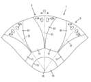
- FIG. 2 is a partially enlarged plan view of the rotor of the electric motor according to the first embodiment.
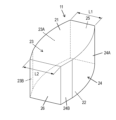
- FIG. 3 is a perspective view of a permanent magnet of the rotor of the first embodiment.
- FIG. 4 is a schematic diagram showing magnetic flux distribution in the electric motor of the first embodiment.
- FIG. 5 is a partially enlarged schematic diagram showing the magnetic flux distribution in the electric motor of the first embodiment.
- FIG. 6 is a partially enlarged plan view of a rotor of an electric motor according to the second embodiment.
- FIG. 7 is a partially enlarged plan view of a rotor of an electric motor according to the third embodiment.
- the electric motor 1 is an inner rotor type motor.
- Fig. 1 is a plan view of the electric motor 1 according to the first embodiment.
- Fig. 2 is a partially enlarged plan view of the rotor 3 of the electric motor 1 according to the first embodiment.
- Fig. 3 is a perspective view of a permanent magnet 11 of the rotor 3 according to the first embodiment.
- the electric motor 1 has a stator 2 and a rotor 3.
- the direction in which the axis 14 (described below) of the rotating shaft 10 (described below) extends is referred to as the axial direction
- the circumferential direction of the rotor 3 is referred to as the circumferential direction C1.
- the case when viewed from the axial direction is referred to as "in a plan view.”
- the direction from a specified position on the electric motor 1 toward the axis is referred to as the "radial inner side.”
- the direction facing away from the axis when viewed from a specified position on the electric motor 1 is referred to as the "radial outer side.”
- the stator 2 is a stator having a stator core 4 and multiple (12 in FIG. 1) coils 5.
- the stator core 4 is a laminated core in which multiple electromagnetic steel sheets are stacked in the thickness direction.
- the stator core 4 has an annular core back 7 and multiple (12 in FIG. 1) teeth 8, and is formed in a generally cylindrical column shape as a whole.
- the multiple teeth 8 are arranged at regular intervals along the circumferential direction C1 on the inner surface of the core back 7, and extend radially inward.
- the multiple coils 5 each correspond to the multiple teeth 8, and each coil 5 is formed by winding a conductor around the corresponding tooth 8.
- the rotor 3 is an IPM (Interior Permanent Magnet) type rotor with permanent magnets embedded inside the rotor core. More specifically, the rotor 3 has a so-called spoke-type rotor structure in which a pair of magnetic pole faces of the magnets are arranged so that they each face in the circumferential direction.
- the rotor 3 is arranged radially inside the stator 2, and includes a rotor core 9, a rotating shaft 10, and multiple (ten in FIG. 1) permanent magnets 11.
- the permanent magnets 11 are members that generate magnetic flux that serves as the driving force for the rotor 3, and are magnetized so that the direction of the magnetic poles is along the circumferential direction C1 of the rotor core 9.
- the electric motor 1 operates as follows. Three-phase currents with a phase difference of 120° electrical angle are supplied to the coils 5 through the power supply connection, exciting the stator 2 and generating a rotating magnetic field. This rotating magnetic field interacts with the magnetic field generated by the permanent magnets 11 provided in the rotor 3, generating a rotational torque in the rotor 3, causing the rotor 3 to rotate around the axis 14.
- the rotor core 9 is a laminated core in which a plurality of electromagnetic steel sheets are laminated in the thickness direction.
- the lamination direction of the plurality of electromagnetic steel sheets is along the axis (hereinafter referred to as the axis direction).
- the rotor core 9 has a circular axial hole 12 and is formed in a cylindrical shape. In the center of the rotor core 9, an axial hole 12 is formed that penetrates the rotor core 9 in the axial direction and opens at both end faces.
- the rotor core 9 has a plurality of outer parts 91 (10 in FIG. 1) and an inner part 92.
- the plurality of outer parts 91 are lined up along the circumferential direction C1, and a magnet arrangement hole 13 is formed between the outer parts 91 adjacent in the circumferential direction C1.
- the inner part 92 is an annular part that connects the radial inner ends of the plurality of outer parts 91, i.e., the parts of each of the plurality of outer parts 91 that are closest to the axis 14.
- a plurality of magnet arrangement holes 13 are formed lined up in the circumferential direction C1.
- the magnet arrangement hole 13 is open on its radially outward side.
- the magnet arrangement hole 13 penetrates in the axial direction, but may have a bottom in the axial direction.
- the rotating shaft 10 is a cylindrical member, and has a shaft center 14 that is the center of rotation.
- the rotating shaft 10 is inserted into a shaft hole 12 of the rotor core 9 and fixed therein.
- Each of the multiple permanent magnets 11 is inserted into a corresponding one of the multiple magnet arrangement holes 13 in the rotor core 9 and fixed using an adhesive or the like.
- a sintered ferrite magnet is used as the permanent magnet 11.
- the permanent magnet 11 may also be a samarium-cobalt permanent magnet, a neodymium magnet, or the like.
- the permanent magnet 11 has approximately the same shape and dimensions as the magnet placement hole 13. Therefore, below, the shape of the permanent magnet 11 will be described in detail, and a description of the shape of the magnet placement hole 13 will be omitted.
- the permanent magnets 11 are roughly rectangular parallelepipeds, and in plan view are shaped like radially elongated spokes (i.e., the longitudinal direction of the permanent magnets 11 is aligned with the radial direction of the rotor 3), and are aligned along the circumferential direction C1.
- the magnetization direction of the permanent magnets 11 is parallel to the circumferential direction C1 of the rotor 3, meaning that two adjacent permanent magnets 11 in the circumferential direction C1 are magnetized so that the two magnetic pole faces facing each other in the circumferential direction C1 are of the same polarity.
- a magnetic pole center line 31 which is an imaginary line that extends radially outward from the axis 14, and the two permanent magnets 11 are arranged symmetrically with respect to the magnetic pole center line 31 in a plan view.
- the permanent magnet 11 has an upper surface 21, a lower surface 22, a first circumferential end face 23 (side face), a second circumferential end face 24 (side face), an outer end face 25 (radially outer end face), and an inner end face 26 (radially inner end face).
- first circumferential end face 23 and the second circumferential end face 24 extend radially
- the outer end face 25 and the inner end face 26 extend in the circumferential direction C1.
- the length of the first circumferential end face 23 and the second circumferential end face 24 is at least twice and at most 20 times the length of the outer end face 25 and the inner end face 26. This allows the area of the rotor core 9 to be used effectively.
- the upper surface 21 and the lower surface 22 are flat surfaces and have the same shape when viewed from above.
- the first circumferential end face 23 and the second circumferential end face 24 are side faces facing the circumferential direction C1 and are also magnetic pole faces.
- the first circumferential end face 23 is a protruding surface that protrudes in the circumferential direction C1 beyond the imaginary plane 32 connecting the inner end and outer end.
- the second circumferential end face 24 is a protruding surface that protrudes in the circumferential direction C1 beyond the imaginary plane 32 connecting the inner end and outer end.
- the first circumferential end face 23 has a first curved surface 23A and a first plane 23B.
- the first curved surface 23A extends from the radially outer side toward the radially inner side.
- the first curved surface 23A is a smooth curved surface that is convex in the circumferential direction C1, and is curved in a plan view.
- the first plane 23B is disposed radially inside the first curved surface 23A.
- the first plane 23B is a plane that is straight in a plan view.
- the first plane 23B is parallel to the magnetic pole center line 31 in a plan view.
- the circumferential width of the radially inner part of the permanent magnet 11, i.e., the part closer to the axis 14 than the center of the permanent magnet 11, can be secured to be wide.
- the radial length of the first plane 23B is 50% or less of the radial length of the entire first circumferential end face 23.
- the second circumferential end face 24 has a second curved surface 24A and a second plane surface 24B.
- the second curved surface 24A extends from the radially outer side toward the radially inner side.
- the second curved surface 24A is a smooth curved surface that is convex in the circumferential direction C1, and is curved in a plan view.
- the second plane surface 24B is disposed radially inward of the second curved surface 24A.
- the second plane surface 24B is a flat surface that is straight in a plan view.
- the second plane surface 24B is parallel to the magnetic pole center line 31 in a plan view.
- the outer end surface 25 is flat and is located radially outward of the permanent magnet 11.
- the outer end surface 25 extends generally along the circumferential direction C1 in a plan view.
- the inner end surface 26 is flat and is located radially inward of the permanent magnet 11.
- the inner end surface 26 extends generally along the circumferential direction C1 in a plan view.
- the circumferential length L1 of the outer end face 25 is shorter than the circumferential length L2 of the inner end face 26. Specifically, the circumferential length L1 of the outer end face 25 is in the range of 60 to 80% of the circumferential length L2 of the inner end face 26.
- the normals of the first circumferential end face 23 and the second circumferential end face 24 face further radially outward. As a result, the magnetic flux emanating from the first curved surface 23A of the first circumferential end face 23 and the second curved surface 24A of the second circumferential end face 24 tends to face radially outward, that is, toward the stator 2. Therefore, the torque of the electric motor 1 can be further improved.
- the rotor core 9 has two holes 41, 42 between two permanent magnets 11 adjacent to each other in the circumferential direction C1.
- Each of the two holes 41, 42 is a through hole extending along the axial direction of the rotating shaft 10.
- the two holes 41, 42 are provided on the outer periphery of the rotor core 9.
- the holes 41, 42 are aligned along the circumferential direction C1.
- the holes 41, 42 are significantly smaller than, for example, the magnet arrangement hole 13.
- the total area of the two holes 41, 42 is 20% or less of the area of one magnet arrangement hole 13.
- the two holes 41, 42 are provided symmetrically with respect to the magnetic pole center line 31.
- the holes 41, 42 are each circular in a plan view.
- FIG. 4 is a schematic diagram showing the magnetic flux distribution in the electric motor 1 of the first embodiment.
- Figure 5 is a partially enlarged schematic diagram showing the magnetic flux distribution in the electric motor 1 of the first embodiment.
- Magnetic field lines M extend from the permanent magnet 11 and extend radially outward from the permanent magnet 11. The magnetic field lines M then branch off to avoid holes 41 and 42, which have a larger magnetic resistance than the surrounding areas. In other words, the magnetic field lines M branch off into three locations: between the holes 41 and 42, between the permanent magnet 11 and the hole 41, and between the permanent magnet 11 and the hole 42, and use each of these as a path.
- the magnetic flux path formed by the two holes 41, 42 is symmetrical with respect to the magnetic pole center line 31, which further reduces torque ripple.
- the two holes 41, 42 are provided at positions where the magnetic flux density between the two holes 41, 42 at no load is ⁇ 40% or less of the magnetic flux density between the permanent magnet 11 and the hole closest to the permanent magnet 11 at no load. Therefore, the difference in magnetic flux density in the multiple magnetic flux paths is reduced, thereby reducing torque ripple.
- the distance between the holes 41, 42 may be ⁇ 85% of the distance between the permanent magnet 11 and the hole 41 or hole 42.
- the two holes 41, 42 are provided on the outer periphery of the rotor core 9, i.e., in an area within the rotor core 9 that is farther from the center of the rotor core 9 when viewed from the axis 14. In this way, since multiple holes 41, 42 are provided at positions away from the axis 14, the flow of magnetic flux near the stator 2 can be adjusted, and therefore torque ripple can be reduced.
- the two holes 41, 42 are located near the outer periphery of the rotor core 9, so the above effect is high.
- multiple holes 41, 42 penetrate in the axial direction, which increases the effect of making the magnetic resistance different from the surroundings, thereby contributing to reducing torque ripple.
- the rotor core may be a dust core whose main component is a dust material obtained by compressing a powdered magnetic body.
- the side surface of the permanent magnet may consist of curved surfaces only.
- the two sides of the permanent magnet may have different shapes.
- the magnets may be bonded magnets made by mixing and kneading magnet powder, which is a hard magnetic material, with a binder such as resin or rubber and molding it, or they may be sintered magnets made by baking magnet powder at high temperature.
- Fig. 6 is a partially enlarged plan view of the rotor 3 of the electric motor 1 according to the second embodiment. Note that the basic configuration and operation of the electric motor 1 according to the second embodiment are similar to those of the electric motor 1 according to the first embodiment, and therefore the following description will focus on the differences.
- the outer portion 91 of the rotor core 9 has two holes 41A, 42A between two adjacent permanent magnets 11 in the circumferential direction C1.
- Each of the two holes 41A, 42A is a through hole extending along the axial direction of the rotating shaft 10.
- the two holes 41A, 42A are provided on the outer periphery of the rotor core 9.
- the holes 41A, 42A are aligned along the circumferential direction C1.
- the holes 41A, 42A are significantly smaller than, for example, the magnet arrangement hole 13.
- the two holes 41A, 42A are provided symmetrically with respect to the magnetic pole center line 31.
- the holes 41A, 42A are each elliptical in plan view. Specifically, the major axes of the holes 41A, 42A are generally along the radial direction, and the minor axes are generally along the circumferential direction C1.
- the two holes 41A, 42A are located at positions where the magnetic flux density between the two holes 41A, 42A when no load is applied is less than ⁇ 40% of the magnetic flux density between the permanent magnet 11 and the hole closest to the permanent magnet 11 when no load is applied. Therefore, the difference in magnetic flux density between the multiple magnetic flux paths is reduced, and therefore torque ripple is reduced.
- the two holes 41A, 42A are provided on the outer periphery of the rotor core 9, i.e., in an area within the rotor core 9 that is farther from the center of the rotor core 9 when viewed from the axis 14. In this way, since multiple holes 41A, 42A are provided at positions away from the axis 14, the flow of magnetic flux near the stator 2 can be adjusted, and therefore torque ripple can be reduced.
- the two holes 41A, 42A are located near the outer periphery of the rotor core 9, so the above effect is high.
- Fig. 7 is a partially enlarged plan view of the rotor 3 of the electric motor 1 according to the third embodiment. Note that the basic configuration and operation of the electric motor 1 according to the third embodiment are similar to those of the electric motor 1 according to the first embodiment, and therefore the following description will focus on the differences.
- the outer portion 91 of the rotor core 9 has four holes 41B, 42B, 43B, and 44B between two adjacent permanent magnets 11 in the circumferential direction C1.
- the four holes 41B, 42B, 43B, and 44B are through holes extending along the axial direction of the rotating shaft 10.
- the four holes 41B, 42B, 43B, and 44B are provided on the outer periphery of the rotor core 9.
- Each of the holes 41B, 42B, 43B, and 44B is aligned along the circumferential direction C1.
- the holes 41B and 42B are significantly smaller than, for example, the magnet arrangement hole 13.
- the pair of holes 41B and 42B and the pair of holes 43B and 44B are provided symmetrically with respect to the magnetic pole center line 31.
- the holes 41B, 42B, 43B, and 44B are each circular in a plan view.
- the four holes 41B, 42B, 43B, and 44B are positioned so that the magnetic flux density between the four holes 41B, 42B, 43B, and 44B when no load is applied is within ⁇ 40% of the magnetic flux density between the permanent magnet 11 and the hole closest to the permanent magnet 11 when no load is applied. Therefore, the difference in magnetic flux density between the multiple magnetic flux paths is reduced, and torque ripple is therefore reduced.
- the four holes 41B, 42B, 43B, 44B are provided on the outer periphery of the rotor core 9, i.e., in an area within the rotor core 9 that is farther from the center of the rotor core 9 when viewed from the axis 14. In this way, since multiple holes 41B, 42B, 43B, 44B are provided at positions away from the axis 14, the flow of magnetic flux near the stator 2 can be adjusted, and therefore torque ripple can be reduced.
- the four holes 41B, 42B, 43B, 44B are located near the outer periphery of the rotor core 9, so the above effect is high.
- the number of holes may be three or may be five or more.
- the holes do not need to penetrate the rotor core 9.
- the shape of the hole is not limited to the first to third embodiments.
- the hole may be polygonal, or may have a shape obtained by combining curved and straight lines.
- the multiple holes are preferably arranged in a circumferential direction, but may be provided at different radial positions.
- the multiple holes do not have to all be the same shape or size, and may include holes of different shapes and sizes.
- the rotor (3) of the first aspect comprises a rotor core (9), a plurality of permanent magnets (11), and a rotating shaft.
- the rotor core (9) has a plurality of magnet arrangement holes (13) arranged in the circumferential direction (C1).
- the plurality of permanent magnets (11) are respectively arranged in the plurality of magnet arrangement holes (13).
- the rotating shaft is fixed to the rotor core (9) and has a center of rotation about the axis (14).
- Each of the plurality of permanent magnets (11) has an inner end face (26), an outer end face (25), and a pair of side faces (23, 24).
- the inner end face (26) faces the axis (14) of the rotating shaft (10) in a plane having a normal line coinciding with the axis (14) of the rotating shaft (10).
- the outer end face (25) faces in the opposite direction to the axis (14) of the rotating shaft (10) in a plane having a normal line coinciding with the axis (14) of the rotating shaft (10).
- the pair of side faces (23, 24) protrude in the circumferential direction from an imaginary plane (32) that connects the circumferential edge of the inner end face (26) and the circumferential edge of the outer end face (25).
- the pair of side faces (23, 24) are magnetic pole faces, and the magnetic pole faces of the same polarity of two permanent magnets (11) adjacent in the circumferential direction (C1) among the multiple permanent magnets (11) are arranged facing each other in the circumferential direction (C1).
- the circumferential length (L1) of the outer end face (25) is shorter than the circumferential length (L2) of the inner end face (26).
- the rotor core (9) has multiple holes (41, 42, 41A, 42A, 41B, 42B, 43B, 44B) between adjacent permanent magnets in the circumferential direction (C1) of the multiple permanent magnets (11).
- the pair of side surfaces (23, 24) protrude outward in the circumferential direction, the effective area of the magnetic pole face of the permanent magnet (11) is increased, and the amount of magnetic flux is increased, and therefore the average torque of the electric motor (1) is increased. Furthermore, the further outward in the radial direction, the more the normal line of the pair of side surfaces (23, 24) faces radially outward. As a result, the magnetic flux coming from the part of the pair of side surfaces (23, 24) opposite the axis (14) is likely to face the opposite side to the axis (14). Therefore, the torque of the electric motor (1) can be further improved. Furthermore, by providing multiple holes (41, 42, 41A, 42A, 41B, 42B, 43B, 44B), the location where the magnetic flux flows can be adjusted. As a result of the above, the torque ripple can be reduced while maintaining the average torque.
- the multiple holes (41, 42, 41A, 42A, 41B, 42B, 43B, 44B) are arranged symmetrically with respect to the magnetic pole center line (31) between the circumferentially adjacent permanent magnets of the multiple permanent magnets (11).
- the magnetic flux path formed by the multiple holes (41, 42, 41A, 42A, 41B, 42B, 43B, 44B) is symmetrical with respect to the magnetic pole center line (31), thereby reducing torque ripple.
- the multiple holes are provided at positions where the magnetic flux density at no load between the multiple holes (41, 42, 41A, 42A, 41B, 42B, 43B, 44B) is ⁇ 40% or less of the magnetic flux density at no load between one of the multiple permanent magnets (11) and the hole closest to the permanent magnet (11).
- the difference in magnetic flux density in the magnetic flux path formed by the multiple holes is reduced, thereby reducing torque ripple.
- the multiple holes are provided in an area of the rotor core (9) farther from the center of the rotor core (9) when viewed from the shaft center (14).
- multiple holes are provided at positions away from the axis, so that the flow of magnetic flux near the stator (2) can be adjusted, thereby reducing torque ripple.
- the holes (41, 42, 41A, 42A, 41B, 42B, 43B, 44B) are through holes extending along the axial direction of the rotating shaft (10).
- multiple holes penetrate in the axial direction, which increases the effect of making the magnetic resistance different from the surroundings, thereby reducing torque ripple.
- each of the pair of side surfaces (23, 24) has a curved surface or a combination of a curved surface and a flat surface.
- the volume of the permanent magnet (11) and the orientation of the side surfaces can be appropriately set by adjusting the shape of a pair of side surfaces, and as a result, torque ripple can be reduced while maintaining the average torque.
- each of the pair of side surfaces (23, 24) has a curved surface (23A, 24A) that is convex outward in the circumferential direction, and a flat surface (23B, 24B) that is disposed on the axial center (14) side of the curved surface (23A, 24A).
- each of the pair of side surfaces (23, 24) has a flat surface (23B, 24B), the portions of the side surfaces (23, 24) facing the axis (14) can be brought closer to each other in the circumferential direction (C1), thereby increasing the volume of the permanent magnet (11).
- the planes (23B, 24B) are parallel to the magnetic pole center line (31) between the multiple permanent magnets (11) when viewed along the axial direction of the rotating shaft (10).
- the planes (23B, 24B) of the pair of side surfaces (23, 24) are parallel to the magnetic pole center line (31), so that the portions of the side surfaces (23, 24) on the axis (14) side can be brought closer to each other in the circumferential direction (C1), thereby increasing the volume of the permanent magnet (11).
- the electric motor (1) according to the ninth aspect includes a rotor (3) according to any one of the first to eighth aspects and a stator (2).
- This embodiment allows torque ripple to be reduced while maintaining average torque.
- the rotor and motor disclosed herein can reduce torque ripple while maintaining average torque. Therefore, the rotor and motor disclosed herein are industrially useful.
Landscapes
- Engineering & Computer Science (AREA)
- Power Engineering (AREA)
- Permanent Field Magnets Of Synchronous Machinery (AREA)
Abstract
La présente invention concerne un rotor et un moteur aptes à réduire les ondulations de couple tout en maintenant un couple moyen. Dans ce rotor (3), une première surface d'extrémité circonférentielle (23) et une seconde surface d'extrémité circonférentielle (24) de chacun d'une pluralité d'aimants permanents (11) font saillie dans la direction circonférentielle à partir d'un plan virtuel (32) qui relie le bord circonférentiel d'une surface d'extrémité interne (26) et le bord circonférentiel d'une surface d'extrémité externe (25). La première surface d'extrémité circonférentielle (23) et la seconde surface d'extrémité circonférentielle (24) sont des surfaces de pôle magnétique, et des surfaces de pôle magnétique du même pôle de deux aimants permanents (11), qui sont adjacentes l'une à l'autre dans une direction circonférentielle (C1) parmi la pluralité d'aimants permanents (11), sont disposées pour se faire face dans la direction circonférentielle (C1). La longueur circonférentielle (L1) de la surface d'extrémité externe (25) est plus courte que la longueur circonférentielle (L2) de la surface d'extrémité interne (26). Dans un noyau de rotor (9), une pluralité de trous (41), (42) sont disposés entre les aimants permanents qui sont adjacents les uns aux autres dans la direction circonférentielle (C1) de la pluralité d'aimants permanents (11).
Applications Claiming Priority (2)
| Application Number | Priority Date | Filing Date | Title |
|---|---|---|---|
| JP2022-160465 | 2022-10-04 | ||
| JP2022160465 | 2022-10-04 |
Publications (1)
| Publication Number | Publication Date |
|---|---|
| WO2024075469A1 true WO2024075469A1 (fr) | 2024-04-11 |
Family
ID=90607841
Family Applications (1)
| Application Number | Title | Priority Date | Filing Date |
|---|---|---|---|
| PCT/JP2023/032944 WO2024075469A1 (fr) | 2022-10-04 | 2023-09-11 | Rotor et moteur |
Country Status (1)
| Country | Link |
|---|---|
| WO (1) | WO2024075469A1 (fr) |
Citations (3)
| Publication number | Priority date | Publication date | Assignee | Title |
|---|---|---|---|---|
| WO2020196382A1 (fr) * | 2019-03-27 | 2020-10-01 | ダイキン工業株式会社 | Noyau de rotor et procédé de fabrication associé |
| JP2021184700A (ja) * | 2017-08-01 | 2021-12-02 | 株式会社デンソー | 磁石の製造方法、及び磁石配向装置 |
| JP2021197749A (ja) * | 2020-06-09 | 2021-12-27 | 公立大学法人秋田県立大学 | 回転電機 |
-
2023
- 2023-09-11 WO PCT/JP2023/032944 patent/WO2024075469A1/fr unknown
Patent Citations (3)
| Publication number | Priority date | Publication date | Assignee | Title |
|---|---|---|---|---|
| JP2021184700A (ja) * | 2017-08-01 | 2021-12-02 | 株式会社デンソー | 磁石の製造方法、及び磁石配向装置 |
| WO2020196382A1 (fr) * | 2019-03-27 | 2020-10-01 | ダイキン工業株式会社 | Noyau de rotor et procédé de fabrication associé |
| JP2021197749A (ja) * | 2020-06-09 | 2021-12-27 | 公立大学法人秋田県立大学 | 回転電機 |
Similar Documents
| Publication | Publication Date | Title |
|---|---|---|
| US9502929B2 (en) | Rotor and motor | |
| US9071118B2 (en) | Axial motor | |
| US7679260B2 (en) | Axial gap motor | |
| US7595575B2 (en) | Motor/generator to reduce cogging torque | |
| US5962944A (en) | Permanent magnet rotor type electric motor | |
| AU2011303910B2 (en) | Rotor for modulated pole machine | |
| US9041269B2 (en) | Motor | |
| CN101663806B (zh) | 轴向间隙型电机 | |
| US8937418B2 (en) | Rotor core, rotor, and rotating electric machine | |
| WO2007072707A1 (fr) | Moteur électrique et son rotor, et noyau magnétique pour le rotor | |
| WO2014115436A1 (fr) | Mécanisme électrique rotatif du type à aimants permanents | |
| JP2011050216A (ja) | 電動機 | |
| US11837919B2 (en) | Rotary electric machine | |
| JP5066863B2 (ja) | 回転電機 | |
| WO2019038958A1 (fr) | Machine électrique tournante | |
| EP4325694A1 (fr) | Rotor, moteur de type disque, système motorisé et véhicule | |
| WO2017171037A1 (fr) | Rotor et procédé de conception de rotor | |
| WO2024075469A1 (fr) | Rotor et moteur | |
| JP5041415B2 (ja) | アキシャルギャップ型モータ | |
| JP2007089304A (ja) | 永久磁石式回転電機 | |
| JP2015142434A (ja) | アキシャル立体ギャップ式回転電機 | |
| JP5128800B2 (ja) | ハイブリッド式永久磁石回転電機 | |
| JP2018098936A (ja) | 磁石ユニット | |
| TW202118193A (zh) | 電動機 | |
| WO2018101160A1 (fr) | Unité d'aimant |
Legal Events
| Date | Code | Title | Description |
|---|---|---|---|
| 121 | Ep: the epo has been informed by wipo that ep was designated in this application |
Ref document number: 23874598 Country of ref document: EP Kind code of ref document: A1 |