WO2024075437A1 - 分注装置およびプローブの状態確認方法 - Google Patents
分注装置およびプローブの状態確認方法 Download PDFInfo
- Publication number
- WO2024075437A1 WO2024075437A1 PCT/JP2023/031390 JP2023031390W WO2024075437A1 WO 2024075437 A1 WO2024075437 A1 WO 2024075437A1 JP 2023031390 W JP2023031390 W JP 2023031390W WO 2024075437 A1 WO2024075437 A1 WO 2024075437A1
- Authority
- WO
- WIPO (PCT)
- Prior art keywords
- probe
- dispensing device
- dispensing
- control unit
- amount
- Prior art date
- Legal status (The legal status is an assumption and is not a legal conclusion. Google has not performed a legal analysis and makes no representation as to the accuracy of the status listed.)
- Ceased
Links
Images




Classifications
-
- G—PHYSICS
- G01—MEASURING; TESTING
- G01N—INVESTIGATING OR ANALYSING MATERIALS BY DETERMINING THEIR CHEMICAL OR PHYSICAL PROPERTIES
- G01N35/00—Automatic analysis not limited to methods or materials provided for in any single one of groups G01N1/00 - G01N33/00; Handling materials therefor
- G01N35/00584—Control arrangements for automatic analysers
- G01N35/00594—Quality control, including calibration or testing of components of the analyser
- G01N35/00613—Quality control
- G01N35/00623—Quality control of instruments
-
- G—PHYSICS
- G01—MEASURING; TESTING
- G01N—INVESTIGATING OR ANALYSING MATERIALS BY DETERMINING THEIR CHEMICAL OR PHYSICAL PROPERTIES
- G01N35/00—Automatic analysis not limited to methods or materials provided for in any single one of groups G01N1/00 - G01N33/00; Handling materials therefor
- G01N35/10—Devices for transferring samples or any liquids to, in, or from, the analysis apparatus, e.g. suction devices, injection devices
- G01N35/1009—Characterised by arrangements for controlling the aspiration or dispense of liquids
- G01N35/1011—Control of the position or alignment of the transfer device
-
- G—PHYSICS
- G01—MEASURING; TESTING
- G01N—INVESTIGATING OR ANALYSING MATERIALS BY DETERMINING THEIR CHEMICAL OR PHYSICAL PROPERTIES
- G01N35/00—Automatic analysis not limited to methods or materials provided for in any single one of groups G01N1/00 - G01N33/00; Handling materials therefor
- G01N35/10—Devices for transferring samples or any liquids to, in, or from, the analysis apparatus, e.g. suction devices, injection devices
- G01N35/1009—Characterised by arrangements for controlling the aspiration or dispense of liquids
-
- G—PHYSICS
- G01—MEASURING; TESTING
- G01N—INVESTIGATING OR ANALYSING MATERIALS BY DETERMINING THEIR CHEMICAL OR PHYSICAL PROPERTIES
- G01N35/00—Automatic analysis not limited to methods or materials provided for in any single one of groups G01N1/00 - G01N33/00; Handling materials therefor
- G01N35/10—Devices for transferring samples or any liquids to, in, or from, the analysis apparatus, e.g. suction devices, injection devices
- G01N35/1079—Devices for transferring samples or any liquids to, in, or from, the analysis apparatus, e.g. suction devices, injection devices with means for piercing stoppers or septums
-
- G—PHYSICS
- G01—MEASURING; TESTING
- G01N—INVESTIGATING OR ANALYSING MATERIALS BY DETERMINING THEIR CHEMICAL OR PHYSICAL PROPERTIES
- G01N35/00—Automatic analysis not limited to methods or materials provided for in any single one of groups G01N1/00 - G01N33/00; Handling materials therefor
- G01N35/10—Devices for transferring samples or any liquids to, in, or from, the analysis apparatus, e.g. suction devices, injection devices
- G01N35/1009—Characterised by arrangements for controlling the aspiration or dispense of liquids
- G01N35/1011—Control of the position or alignment of the transfer device
- G01N2035/1013—Confirming presence of tip
-
- G—PHYSICS
- G01—MEASURING; TESTING
- G01N—INVESTIGATING OR ANALYSING MATERIALS BY DETERMINING THEIR CHEMICAL OR PHYSICAL PROPERTIES
- G01N35/00—Automatic analysis not limited to methods or materials provided for in any single one of groups G01N1/00 - G01N33/00; Handling materials therefor
- G01N35/10—Devices for transferring samples or any liquids to, in, or from, the analysis apparatus, e.g. suction devices, injection devices
- G01N2035/1027—General features of the devices
- G01N2035/103—General features of the devices using disposable tips
Definitions
- Patent Document 1 discloses an automatic analyzer that monitors the penetration performance to determine when to replace the probe, because when the same probe is repeatedly used to pierce and dispense the specimen from the container stopper, the tip of the probe's ability to penetrate the stopper deteriorates due to wear and tear.
- Patent Document 1 only monitors the penetration performance of the probe, so even if it can reliably penetrate the stopper of a container, it does not necessarily guarantee accuracy when dispensing liquid.
- the stopper is repeatedly penetrated with the probe, the length of the probe becomes shorter, which causes variation in the action of bringing the probe into contact with the reaction container when dispensing the sample, which may result in reduced dispensing accuracy.
- the object of the present invention is to provide a dispensing device and a method for checking the state of a probe that can determine the appropriate time to replace the probe while suppressing a decrease in dispensing accuracy.
- the present invention provides a dispensing device that includes a probe for aspirating and dispensing liquid, a sensor for detecting contact of the tip of the probe, a drive unit for driving the probe in vertical directions, and a control unit for controlling the drive unit.
- the control unit performs an operation to check the change in length of the probe by lowering the probe using the drive unit until it detects contact with a predetermined reference surface that is part of the dispensing device.
- the present invention makes it possible to provide a dispensing device and a method for checking the state of a probe that can determine the appropriate time to replace the probe while suppressing deterioration in dispensing accuracy.
- FIG. 1 is a schematic diagram showing the main configuration of an automatic analyzer.
- FIG. 2 is a schematic diagram showing the configuration of a sample dispensing mechanism.
- FIG. 13 is a diagram for explaining a mechanism for detecting contact of the tip of a sample dispensing probe.
- 13A and 13B are diagrams showing the positional relationship between a new sample dispensing probe, a sample dispensing probe with a worn tip, and a reference surface.
- 10 is a flowchart showing an operation for measuring the length of a probe before use. 4 is a time chart showing an operation when measuring a probe length. 10 is a flowchart showing an operation for checking the state of a probe based on a change in the probe length.
- FIG. 11 is a diagram showing the positional relationship between the pre-use probe and the post-use probe and the reaction vessel when the probe is lowered by a specified amount from the origin height.
- FIG. 13 is a schematic diagram showing the concept of correcting the probe lowering amount. 13 is a graph showing an example of the relationship between the amount of change in the probe lowering distance and the number of dispensings.
- FIG. 13 is a diagram showing an example of a probe status confirmation screen.
- FIG. 13 is a diagram showing an example of a probe length setting screen.
- an automatic analyzer will be described as an example.
- automatic analyzers include automatic biochemical analyzers, automatic immunological analyzers, and automatic genetic analyzers.
- this is merely one example of an automatic analyzer, and it broadly includes devices that analyze samples by mixing samples such as plasma, serum, and urine with various reagents.
- it also includes mass spectrometers used in clinical tests and coagulation analyzers that measure blood clotting time. It is also applicable to composite systems of these with automatic biochemical analyzers and automatic immunological analyzers, or automatic analysis systems that apply these.
- Fig. 1 is a schematic diagram showing the main components of an automatic analyzer.
- the automatic analyzer includes a computer 1, a sample dispensing mechanism 2, a reagent cooler 5, a reagent dispensing mechanism 3, and the like.
- Computer 1 has an output section, an input section, and a memory section.
- the output section displays analysis results, alarms, etc. to the user, and is, for example, a display.
- the input section allows the user to input characters and numbers in order to set the operating conditions of the device, and is, for example, a keyboard.
- the memory section stores analysis results and setting values, and is, for example, a memory. The user operates the input section while looking at the output section to request analysis and make various settings.
- the specimen dispensing mechanism 2 aspirates specimens from specimen containers (not shown in FIG. 1) placed in the device and dispenses them into the reaction container 4.
- the reagent cooler 5 keeps the reagents to be mixed with the specimens cool, and its top is closed with a lid.
- the reagent dispensing mechanism 3 aspirates reagents from a hole in the lid of the reagent cooler 5 and dispenses them into the reaction container 4.
- the specimens and reagents dispensed into the reaction container 4 are mixed by a stirring mechanism (not shown), and a mixed liquid is prepared in the reaction container 4.
- the absorbance of this mixed liquid is measured by an analysis unit (not shown), and the control unit (not shown) calculates the concentration of a specified component contained in the mixed liquid based on the measurement results.
- the control unit also controls the operation of each mechanism, such as the specimen dispensing mechanism.
- [Configuration of Dispensing Mechanism] 2 is a schematic diagram showing the configuration of the sample dispensing mechanism 2.
- the sample dispensing mechanism 2 also includes a horizontal drive unit, a vertical drive unit, a syringe, and the like (not shown).
- the specimen 11 is contained in a specimen container 12, and one or more specimen containers 12 are transported to a dispensing position by a transport mechanism (not shown) while mounted on a specimen rack 14.
- the specimen container 12 is assumed to be a vacuum test tube or the like that is closed with a stopper 13, but an unstoppered specimen container 12 may also be included.
- the control unit When dispensing the sample, the control unit first controls the horizontal drive unit of the sample dispensing mechanism 2 to drive the sample dispensing probe 10 horizontally and move it to a position above the sample container 12. Next, the control unit controls the up-down drive unit of the sample dispensing mechanism 2 to drive the sample dispensing probe 10 vertically downward to pierce the stopper 13 of the sample container 12. Thereafter, the control unit operates the syringe with the sample dispensing probe 10 immersed in the sample 11, thereby aspirating a predetermined amount of sample 11 into the sample dispensing probe 10.
- control unit controls the vertical drive unit to raise the sample dispensing probe 10, and then controls the horizontal drive unit to move the sample dispensing probe 10 to a position above the reaction vessel 4.
- control unit controls the vertical drive unit of the sample dispensing mechanism 2 to lower the sample dispensing probe 10, and then operates the syringe to eject a predetermined amount of sample 11 from the sample dispensing probe 10 into the reaction vessel 4.
- control unit moves the sample dispensing probe 10 to each of the aforementioned positions and stops it
- a control method is used in which the drive unit is stopped based on a detection signal from a specified sensor, or a control method is used in which the drive unit is given a specified amount of movement from the reference position to the stop position.
- the tip of the sample dispensing probe 10 is sharpened so that it can penetrate the stopper 13.
- control unit each time the control unit finishes aspirating and dispensing one sample, it moves the sample dispensing probe 10 to the washing tank 15 and dispensing washing water from the washing tank 15 onto the sample dispensing probe 10, thereby washing the sample dispensing probe 10. This makes it possible to prevent contamination of the previous sample when dispensing another sample with the same sample dispensing probe 10 thereafter.
- FIG. 3 is a diagram illustrating a mechanism for detecting contact of the tip of the sample dispensing probe.
- the sample dispensing mechanism 2 of this embodiment further includes a stopper 21, a detection plate 23, a contact detection sensor 20, and a spring 22.
- the stopper 21 prevents the sample dispensing probe 10 from moving downward beyond a specified range.
- the detection plate 23 is fixed to the sample dispensing probe 10 above the stopper 21 via a connection part 24.
- the contact detection sensor 20 is a sensor that detects contact of the tip of the sample dispensing probe 10 by blocking light when the detection plate 23 enters its light irradiation range (detection range).
- the spring 22 presses downward the connection part 24 that is integral with the sample dispensing probe 10.
- the connecting part 24 When no object is in contact with the tip of the sample dispensing probe 10, as shown on the left side of Figure 3, the connecting part 24 is pressed against the stopper 21 by the pressing force of the spring 22, and is in a positioned state, and the detection plate 23 is not within the detection range of the contact detection sensor 20. However, if an object 25 comes into contact with the tip of the sample dispensing probe 10 while it is descending, as shown on the right side of Figure 3, the connecting part 24 moves upward against the pressing force of the spring 22, and the detection plate 23 also moves upward and enters the detection range of the contact detection sensor 20.
- the control unit controls the vertical drive unit to stop the downward movement of the sample dispensing probe 10.
- the sample dispensing probe 10 stops safely without damaging the device.
- the pressure of the spring 22 presses the connection part 24 against the stopper 21, returning it to its positioned state.
- the object 25 is a reaction vessel 4 or a washing tank 15
- contact is detected by the same behavior.
- the specimen dispensing probe 10 penetrates the stopper 13 of the specimen vessel 12 to aspirate the specimen, it is desirable to control the downward movement of the specimen dispensing probe 10 so as not to stop even if the detection plate 23 enters the detection range of the contact detection sensor 20.
- FIG. 4 is a diagram showing the positional relationship between a new sample dispensing probe, a sample dispensing probe with a worn tip, and a reference surface.
- the position of the probe tip when at the origin height is different between a new sample dispensing probe (hereinafter referred to as a pre-use probe 10a) and a sample dispensing probe with a worn tip (hereinafter referred to as a used probe 10b).
- the origin height of the probe is the probe height when the motor constituting the vertical drive unit of the sample dispensing mechanism 2 is at the origin position.
- the position of the tip of the used probe 10b is higher than the position of the tip of the pre-use probe 10a. This is because the length of the probe becomes shorter when the probe is repeatedly used for dispensing, especially when the probe repeatedly penetrates the stopper 13. Therefore, when the probe is lowered from the origin height until it contacts the reference surface 31, the amount of descent Y of the used probe 10b is longer than the reference amount of descent X of the pre-use probe 10a.
- Fig. 5 is a flow chart showing the operation when measuring the length of a probe before use
- Fig. 6 is a time chart showing the operation when measuring the length of a probe.
- control unit controls the horizontal drive unit of the sample dispensing mechanism 2 to move the pre-use probe 10a to a home position at a specified horizontal position (step S101). Note that when the pre-use probe 10a is at the home position, its vertical position is the same as the origin height described above.
- control unit controls the horizontal drive unit of the sample dispensing mechanism 2 to move the pre-use probe 10a above a predetermined reference plane 31 (see FIG. 4) that is part of the automatic analyzer (step S102).
- the movement at this time is, for example, a parallel movement to the right or a rotational movement in the right direction, which corresponds to the horizontal movement A in FIG. 6.
- control unit controls the vertical drive unit of the sample dispensing mechanism 2 to lower the pre-use probe 10a, and when the contact detection sensor 20 detects contact with the reference surface 31, the control unit stops the descent of the pre-use probe 10a (step S103). At this time, the control unit calculates the amount of descent from the origin height based on the operation log of the vertical drive unit, and stores the calculation result in the memory unit as the reference descent amount X (step S104). Note that when the tip of the pre-use probe 10a contacts the reference surface 31, the detection plate 23 enters the light irradiation range of the contact detection sensor 20 and becomes dark, so that contact is detected as shown in FIG. 6.
- control unit controls the vertical drive unit to raise the pre-use probe 10a to the origin height. Furthermore, the control unit controls the horizontal drive unit to move the pre-use probe 10a to the home position.
- the movement at this time is, for example, a parallel movement to the left or a rotational movement in the left direction, which corresponds to the horizontal movement B in FIG. 6.
- the reference surface 31 is a plane that forms the washing tank 15, for example, there is an advantage that even if a sample adheres to the reference surface 31 due to contact with the sample dispensing probe 10, the sample can be washed by the washing tank 15.
- a portion other than the washing tank 15 may be used as the reference surface 31 as long as it is a flat surface that forms part of the device and whose positional relationship with the device (especially height) does not change, rather than a bottom surface of a container that may cause variation in its positional relationship with the device.
- the reference surface 31 is not limited to a portion already installed in the device, but may be formed by providing a new metallic portion that is difficult to deform within the movement trajectory of the sample dispensing probe 10.
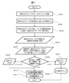
- [Status confirmation method based on changes in probe length] 7 is a flow chart showing the operation for checking the state of the probe based on the change in the length of the probe.
- the operation for checking the state of the probe is started at a predetermined timing described later, the length (descent amount) of the used probe 10b that has worn down due to repeated dispensing is measured.
- control unit controls the horizontal drive unit of the sample dispensing mechanism 2 to move the used probe 10b to a home position located at a specified horizontal position (step S201).
- control unit controls the horizontal drive unit of the sample dispensing mechanism 2 to move the used probe 10b above the reference surface 31 (step S202).
- control unit controls the vertical drive unit of the sample dispensing mechanism 2 to lower the used probe 10b, and when the contact detection sensor 20 detects contact with the reference surface 31, the control unit stops the lowering of the used probe 10b (step S203).
- the control unit calculates the amount of descent from the origin height based on the operation log of the vertical drive unit, and stores the calculation result as the amount of descent Y in the storage unit (step S204).
- the control unit calculates the amount of change in the amount of descent ⁇ (see FIG. 4) from the difference between the amount of descent Y measured in step S204 and the reference amount of descent X measured in FIG. 5 (step S205).
- the control unit calculates the amount of change in the amount of descent ⁇ (see FIG. 4) from the difference between the amount of descent Y measured in step S204 and the reference amount of descent X measured in FIG. 5 (step S205).
- the control unit When the sample dispensing probe 10 wears down due to repeated use, the change in the amount of descent ⁇ gradually increases, and eventually the sample dispensing probe 10 needs to be replaced. For this reason, the control unit outputs a warning alarm (first alarm) at the stage where dispensing is not possible without replacing the sample dispensing probe 10. Furthermore, the control unit outputs a caution alarm (second alarm) even when the time to replace the sample dispensing probe 10 is approaching.
- two types of thresholds are stored in advance in the memory unit. Note that in this embodiment, two types of alarms and two types of thresholds are given as examples, but the number of types of alarms and thresholds may be one or three or more.
- the first threshold A is a threshold for determining whether or not a warning alarm needs to be output, and when the amount of change ⁇ reaches this threshold, it is deemed that the necessary dispensing accuracy cannot be guaranteed and that the probe 10b needs to be replaced after use.
- the second threshold B is a threshold for determining whether or not a caution alarm needs to be output, and when the amount of change ⁇ reaches this threshold, it is deemed that the time to replace the probe 10b after use is approaching. Note that the second threshold B is smaller than the first threshold A, and these thresholds are stored in the memory unit.
- the control unit compares the amount of change ⁇ calculated in step S205 with a first threshold A and a second threshold B (step S206). If the amount of change ⁇ is equal to or greater than the first threshold A, the control unit outputs a warning alarm (step S207) and stops the dispensing operation (step S208). In step S208, if the dispensing operation of a series of samples has not yet started, the control unit may not perform any further dispensing operations, and if the dispensing operation of a series of samples is in progress, the control unit may not perform any dispensing operations after dispensing of the remaining samples has been completed.
- step S206 determines whether the amount of change ⁇ is less than the first threshold value and equal to or greater than the second threshold value B. If it is determined in step S206 that the amount of change ⁇ is less than the first threshold value and equal to or greater than the second threshold value B, the control unit outputs a warning alarm (step S209). In this case, dispensing accuracy can be guaranteed, so the dispensing operation starts and continues (step S210), and when all requested samples have been dispensed, the dispensing operation ends (step S211).
- step S206 determines whether the amount of change ⁇ is less than the second threshold value B. If it is determined in step S206 that the amount of change ⁇ is less than the second threshold value B, the control unit starts and continues the dispensing operation without outputting an alarm (step S210), and ends the dispensing operation when all the samples have been dispensed (step S211).
- Fig. 8 is a diagram showing the positional relationship between the pre-use probe and the post-use probe and the reaction vessel when they are lowered a specified amount from the origin height.
- the positions of the probe tips are different between the pre-use probe 10a and the post-use probe 10b even if they are lowered by the same amount from the origin height. That is, according to FIG. 8, it can be seen that the tip of the pre-use probe 10a is in contact with the bottom surface of the reaction vessel 4, while the tip of the post-use probe 10b is separated from the bottom surface of the reaction vessel 4 by a change amount ⁇ .
- the sample dispensing probe 10 generally ejects the sample while in contact with the bottom surface of the reaction vessel 4.
- the amount of descent of the probe in the sample ejection operation is corrected based on the difference between the amount of descent Y of the probe in the state confirmation operation described above with reference to FIG. 7 and the reference amount of descent X.
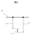
- FIG. 9 is a schematic diagram showing the concept of correcting the probe descent amount.
- the control unit applies a predetermined amount of operation to the vertical drive unit of the sample dispensing mechanism 2 to lower the pre-use probe 10a by the descent amount X1 from the origin height 37.
- the control unit applies a predetermined amount of operation to the vertical drive unit of the sample dispensing mechanism 2 to lower the post-use probe 10b by the corrected descent amount Y1 from the origin height.
- the corrected descent amount Y1 is obtained by adding the change amount ⁇ calculated in the above-mentioned state confirmation operation to the reference pre-correction descent amount X1.
- the probe tip can be reliably brought into contact with the bottom surface of the sample container 12, and dispensing accuracy can be ensured.
- the amount of change ⁇ reaches the first threshold A
- dispensing accuracy can be guaranteed by correcting the amount of probe descent, but once the amount of change reaches the first threshold A, dispensing accuracy cannot be guaranteed by correcting the amount of probe descent, and the probe must be replaced.
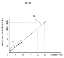
- FIG. 10 is a graph showing an example of the relationship between the amount of change in the probe descent amount and the number of dispensings.
- the amount of change ⁇ in the amount of probe descent is calculated each time the state of the probe 10b is checked after use and stored in the memory unit.
- a plurality of points 51 plotted in FIG. 10 show the transition of the amount of change ⁇ calculated in each checking operation (vertical axis) and the transition of the cumulative number of dispensings at the time of calculation (horizontal axis).
- the control unit generates an approximation curve 52 connecting these plurality of points 51 and the origin, and predicts the number of dispensings N A when the amount of change ⁇ reaches the first threshold A and the number of dispensings N B when the amount of change ⁇ reaches the second threshold B by calculating the slope of the approximation curve 52.
- the control unit outputs the prediction result, thereby notifying the user of the guideline for the time to replace the probe and encouraging the user to prepare for probe replacement.
- the prediction is not limited to the number of dispensings until each threshold is reached. For example, the control unit may predict the number of days until each threshold is reached by creating an approximation curve for the relationship between the amount of change ⁇ and the number of days.
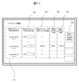
- FIG. 11 is a diagram showing an example of a probe status confirmation screen.
- the control unit reads out the history of the status confirmation operation stored in the storage unit, and displays a status confirmation screen (maintenance history) as shown in FIG. 11 on the output unit.
- the confirmation operation date and time display field 41 displays the date and time when the status confirmation operation of the probe was performed.
- the length change amount display field 42 displays the change amount ⁇ calculated by the status confirmation operation.
- the displayed change amount ⁇ may be the number of pulses applied to the vertical drive unit, but it is easier for the user to understand if it is converted into length.
- the dispensing count display field 43 displays the cumulative number of dispensings when the status confirmation operation was performed. Note that if the change amount ⁇ starts to decrease (becomes zero), this means that the probe has been replaced, so the cumulative number of dispensings may be automatically reset to zero.
- the first threshold A display field 44 displays the remaining number of dispensations until the amount of change ⁇ reaches the first threshold A
- the second threshold B display field 45 displays the remaining number of dispensations until the amount of change ⁇ reaches the second threshold B. The remaining number of dispensations displayed in these fields is predicted by the method described above with reference to FIG.
- the probe status check operation it is desirable for the probe status check operation to be performed periodically; for example, it may be incorporated into the preparatory operations performed at the start of an analysis operation so that it is performed automatically each time an analysis operation is performed. Also, as shown in FIG. 11, a check operation execution button 46 may be provided on the status check screen so that the probe status check operation is immediately executed when this button is operated.
- FIG. 12 is a diagram showing an example of a probe length setting screen.
- the user can appropriately specify the timing of the probe status check operation. For example, the user can specify that the probe status check operation is performed before the start of a series of sample dispensing operations, or that the probe status check operation is performed after the start of a series of sample dispensing operations.
- the status check operation of this embodiment is performed in one cycle, it is possible to perform the operation at that timing even in the middle of a series of dispensing operations if there is an empty cycle.
- a predetermined number of dispensing times may be specified in advance, and the probe status check operation may be performed when the cumulative number of dispensing times reaches the specified number.
- the probe status check operation may be performed when the remaining sample dispensing is completed (e.g., 520 times).
- the present invention is not limited to the above-described embodiment, and various modifications are possible.
- a sensor that detects contact of the probe tip by the intrusion of the detection plate 23 is used as the contact detection sensor 20, but instead of this sensor, a sensor that detects contact of the probe tip by detecting changes in capacitance or pressure may be used.
- a specimen dispensing probe 10 that aspirates and dispenses a specimen is described, but the present invention can also be applied to a dispensing probe that aspirates and dispenses other liquids such as reagents and detergents.
- an automatic analyzer equipped with an analysis unit that analyzes a mixed liquid into which a sample and a reagent have been dispensed has been described as an example, but the present invention can also be applied to a dispensing device that does not have an analysis unit and only dispenses samples.
- the present invention can also be applied to a sample transport device that dispenses a sample from a sample container that has been inserted into a sample insertion unit and closed with a stopper into another container, and transports the container that holds the subdivided sub-sample.
Landscapes
- Physics & Mathematics (AREA)
- Health & Medical Sciences (AREA)
- Life Sciences & Earth Sciences (AREA)
- Chemical & Material Sciences (AREA)
- Analytical Chemistry (AREA)
- Biochemistry (AREA)
- General Health & Medical Sciences (AREA)
- General Physics & Mathematics (AREA)
- Immunology (AREA)
- Pathology (AREA)
- Engineering & Computer Science (AREA)
- Quality & Reliability (AREA)
- Automatic Analysis And Handling Materials Therefor (AREA)
Priority Applications (4)
| Application Number | Priority Date | Filing Date | Title |
|---|---|---|---|
| CN202380070146.0A CN119968564A (zh) | 2022-10-06 | 2023-08-30 | 分注装置以及探头的状态确认方法 |
| US19/113,988 US20260104432A1 (en) | 2022-10-06 | 2023-08-30 | Dispensing device and probe state checking method |
| JP2024555663A JP7822485B2 (ja) | 2022-10-06 | 2023-08-30 | 分注装置およびプローブの状態確認方法 |
| EP23874567.3A EP4600654A1 (en) | 2022-10-06 | 2023-08-30 | Dispensing device and probe state confirmation method |
Applications Claiming Priority (2)
| Application Number | Priority Date | Filing Date | Title |
|---|---|---|---|
| JP2022161559 | 2022-10-06 | ||
| JP2022-161559 | 2022-10-06 |
Publications (1)
| Publication Number | Publication Date |
|---|---|
| WO2024075437A1 true WO2024075437A1 (ja) | 2024-04-11 |
Family
ID=90607739
Family Applications (1)
| Application Number | Title | Priority Date | Filing Date |
|---|---|---|---|
| PCT/JP2023/031390 Ceased WO2024075437A1 (ja) | 2022-10-06 | 2023-08-30 | 分注装置およびプローブの状態確認方法 |
Country Status (5)
| Country | Link |
|---|---|
| US (1) | US20260104432A1 (https=) |
| EP (1) | EP4600654A1 (https=) |
| JP (1) | JP7822485B2 (https=) |
| CN (1) | CN119968564A (https=) |
| WO (1) | WO2024075437A1 (https=) |
Citations (3)
| Publication number | Priority date | Publication date | Assignee | Title |
|---|---|---|---|---|
| JP2015102427A (ja) | 2013-11-26 | 2015-06-04 | 株式会社日立ハイテクノロジーズ | 自動分析装置 |
| JP2020178879A (ja) * | 2019-04-25 | 2020-11-05 | 日本精密測器株式会社 | 呼気検査装置 |
| JP2021173555A (ja) * | 2020-04-21 | 2021-11-01 | キヤノンメディカルシステムズ株式会社 | 自動分析装置 |
-
2023
- 2023-08-30 WO PCT/JP2023/031390 patent/WO2024075437A1/ja not_active Ceased
- 2023-08-30 CN CN202380070146.0A patent/CN119968564A/zh active Pending
- 2023-08-30 EP EP23874567.3A patent/EP4600654A1/en active Pending
- 2023-08-30 US US19/113,988 patent/US20260104432A1/en active Pending
- 2023-08-30 JP JP2024555663A patent/JP7822485B2/ja active Active
Patent Citations (3)
| Publication number | Priority date | Publication date | Assignee | Title |
|---|---|---|---|---|
| JP2015102427A (ja) | 2013-11-26 | 2015-06-04 | 株式会社日立ハイテクノロジーズ | 自動分析装置 |
| JP2020178879A (ja) * | 2019-04-25 | 2020-11-05 | 日本精密測器株式会社 | 呼気検査装置 |
| JP2021173555A (ja) * | 2020-04-21 | 2021-11-01 | キヤノンメディカルシステムズ株式会社 | 自動分析装置 |
Also Published As
| Publication number | Publication date |
|---|---|
| CN119968564A (zh) | 2025-05-09 |
| JP7822485B2 (ja) | 2026-03-02 |
| JPWO2024075437A1 (https=) | 2024-04-11 |
| US20260104432A1 (en) | 2026-04-16 |
| EP4600654A1 (en) | 2025-08-13 |
Similar Documents
| Publication | Publication Date | Title |
|---|---|---|
| US9335335B2 (en) | Automatic analyzer | |
| JP4966913B2 (ja) | 液体分注装置 | |
| US9470570B2 (en) | Automatic analyzer and method for determining malfunction thereof | |
| EP2525230A1 (en) | Automatic analyzing device | |
| US9529009B2 (en) | Automatic analyzer | |
| JP6854292B2 (ja) | 自動分析装置 | |
| US12326459B2 (en) | Automatic analyzer | |
| WO2009132189A1 (en) | Differentiating between abnormal sample viscosities and pipette clogging during aspiration | |
| EP3859350B1 (en) | Automatic analysis system | |
| US20120291532A1 (en) | Methods, Systems, And Apparatus To Determine A Clot Carryout Condition Upon Probe Retraction During Sample Aspiration And Dispensing | |
| US12228585B2 (en) | Automatic analyzer | |
| JP2021092564A (ja) | 密閉液体容器のピペッティングユニットおよびピペッティング方法 | |
| US20120309099A1 (en) | Automatic analyzing device | |
| JP2020030089A (ja) | 分析システム | |
| EP4317982A1 (en) | Automated analysis device | |
| JP7822485B2 (ja) | 分注装置およびプローブの状態確認方法 | |
| WO2014119486A1 (ja) | 自動分析装置 | |
| JP2013148360A (ja) | 自動分析装置、分注機構および分注方法 | |
| JP5492833B2 (ja) | 自動分析装置およびその制御方法 | |
| CN118401842A (zh) | 自动分析装置、分注方法 | |
| JP2013185912A (ja) | 自動分析装置 | |
| EP4737910A1 (en) | Automatic analysis device | |
| JP7638302B2 (ja) | 自動分析装置とその制御方法 | |
| TWI850756B (zh) | 分注裝置及分注方法 | |
| JP2012189514A (ja) | 自動分析装置 |
Legal Events
| Date | Code | Title | Description |
|---|---|---|---|
| 121 | Ep: the epo has been informed by wipo that ep was designated in this application |
Ref document number: 23874567 Country of ref document: EP Kind code of ref document: A1 |
|
| DPE2 | Request for preliminary examination filed before expiration of 19th month from priority date (pct application filed from 20040101) | ||
| WWE | Wipo information: entry into national phase |
Ref document number: 2024555663 Country of ref document: JP |
|
| WWE | Wipo information: entry into national phase |
Ref document number: 202380070146.0 Country of ref document: CN |
|
| WWE | Wipo information: entry into national phase |
Ref document number: 2023874567 Country of ref document: EP |
|
| NENP | Non-entry into the national phase |
Ref country code: DE |
|
| WWP | Wipo information: published in national office |
Ref document number: 202380070146.0 Country of ref document: CN |
|
| ENP | Entry into the national phase |
Ref document number: 2023874567 Country of ref document: EP Effective date: 20250506 |
|
| WWP | Wipo information: published in national office |
Ref document number: 2023874567 Country of ref document: EP |