WO2024075282A1 - 電動機および制御装置 - Google Patents
電動機および制御装置 Download PDFInfo
- Publication number
- WO2024075282A1 WO2024075282A1 PCT/JP2022/037642 JP2022037642W WO2024075282A1 WO 2024075282 A1 WO2024075282 A1 WO 2024075282A1 JP 2022037642 W JP2022037642 W JP 2022037642W WO 2024075282 A1 WO2024075282 A1 WO 2024075282A1
- Authority
- WO
- WIPO (PCT)
- Prior art keywords
- winding
- phase
- windings
- thermistor
- stator core
- Prior art date
- Legal status (The legal status is an assumption and is not a legal conclusion. Google has not performed a legal analysis and makes no representation as to the accuracy of the status listed.)
- Ceased
Links
Images





Classifications
-
- H—ELECTRICITY
- H02—GENERATION; CONVERSION OR DISTRIBUTION OF ELECTRIC POWER
- H02P—CONTROL OR REGULATION OF ELECTRIC MOTORS, ELECTRIC GENERATORS OR DYNAMO-ELECTRIC CONVERTERS; CONTROLLING TRANSFORMERS, REACTORS OR CHOKE COILS
- H02P29/00—Arrangements for regulating or controlling electric motors, appropriate for both AC and DC motors
- H02P29/60—Controlling or determining the temperature of the motor or of the drive
- H02P29/64—Controlling or determining the temperature of the winding
-
- H—ELECTRICITY
- H02—GENERATION; CONVERSION OR DISTRIBUTION OF ELECTRIC POWER
- H02K—DYNAMO-ELECTRIC MACHINES
- H02K11/00—Structural association of dynamo-electric machines with electric components or with devices for shielding, monitoring or protection
- H02K11/20—Structural association of dynamo-electric machines with electric components or with devices for shielding, monitoring or protection for measuring, monitoring, testing, protecting or switching
- H02K11/25—Devices for sensing temperature, or actuated thereby
Definitions
- This disclosure relates to an electric motor and a control device.
- a technique in which the temperature of the windings is measured by a temperature sensor, and the electric motor is stopped if the temperature exceeds a predetermined temperature (for example, Patent Document 1).
- a thermistor or a thermostat is used as the temperature sensor.
- the electric motor disclosed herein comprises a stator core, a first winding wound around the stator core and constituting a first phase, a second winding wound around the stator core and constituting a second phase different from the first phase, a thermistor attached to the first winding, and a thermostat connected in series to the thermistor and attached to the second winding.
- the control device disclosed herein includes a detection unit that detects a combined resistance between the resistance of a thermistor that is wound around the stator core of an electric motor and attached to a first winding that forms a first phase, and the resistance of a thermostat that is wound around the stator core and attached to a second winding that forms a second phase different from the first phase and is connected in series with the thermistor, and an output unit that outputs an alarm when the value of the combined resistance detected by the detection unit is equal to or greater than a first reference value or equal to or less than a second reference value.
- FIG. 2 is a diagram for explaining an electric motor.
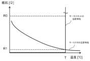
- FIG. 4 is a schematic diagram showing an example of a manner in which a thermistor and a thermostat are attached to each winding. 4 is a graph showing an example of temperature characteristics of a thermistor and a thermostat.
- FIG. 4 is a schematic diagram showing an example of a manner in which a thermistor and a thermostat are attached to each winding.
- FIG. 4 is a schematic diagram showing an example of a manner in which a thermistor and a thermostat are attached to each winding.
- FIG. 4 is a schematic diagram showing an example of a manner in which a thermistor and a thermostat are attached to each winding.
- FIG. 2 is a block diagram showing an example of a hardware configuration of a control device.
- based on XX means “based on at least XX,” and includes cases where it is based on other elements in addition to XX. Furthermore, “based on XX” is not limited to cases where XX is used directly, but also includes cases where it is based on XX that has been calculated or processed. "XX” is any element (for example, any information).
- FIG. 1 is a diagram for explaining an electric motor.
- the electric motor 1 is, for example, a three-phase AC motor.
- the electric motor 1 is not limited to a three-phase AC motor, and may be a single-phase AC motor.
- the electric motor 1 may also be a DC motor.
- the DC motor is, for example, a brushless DC (Direct Current) motor. Note that, hereinafter, each embodiment will be described using a three-phase AC motor.
- the electric motor 1 includes a stator 2 and a rotor 3.
- the stator 2 includes a stator core 21 and a plurality of windings 22.
- the plurality of windings 22 include, for example, a first winding 221a, a second winding 222a, and a third winding 223a.
- the stator core 21 is formed, for example, by stacking multiple electromagnetic steel sheets.
- the electromagnetic steel sheets are processed into a predetermined shape, for example, by press working.
- the stator core 21 includes a circular ring-shaped yoke 211 and multiple teeth 212 that protrude from the inner periphery of the yoke 211 toward the central axis of the stator core 21.
- the first winding 221a is wound around the teeth 212 of the stator core 21.
- the first winding 221a is made of, for example, copper wire.
- the first winding 221a is a winding that forms a first phase.
- the first phase is, for example, a U-phase.
- the second winding 222a is wound around the teeth 212 of the stator core 21.
- the second winding 222a is made of, for example, a copper wire.
- the second winding 222a is a winding that forms a second phase different from the first phase.
- the second phase is, for example, a V phase.
- the third winding 223a is wound around the teeth 212 of the stator core 21.
- the third winding 223a is made of, for example, a copper wire.
- the third winding 223a is a winding that forms a third phase different from the first phase and the second phase.
- the third phase is, for example, the W phase.
- the rotor 3 includes, for example, a permanent magnet 31.
- the rotor 3 rotates due to the magnetic force acting between the stator 2 and the rotor 3.
- the stator 2 further includes a thermistor (not shown) and a thermostat (not shown).
- the thermistor is an electronic component whose resistance value changes in response to changes in temperature.
- the thermistor is, for example, an NTC (negative temperature coefficient) thermistor.
- An NTC thermistor is a thermistor whose resistance value decreases gradually as the temperature increases.
- the thermistor may be a PTC (positive temperature coefficient) thermistor.
- a PTC thermistor is a thermistor whose resistance increases with increasing temperature.
- a thermostat is an electronic component whose resistance is 0 ⁇ below a certain temperature, and whose resistance becomes infinite above that temperature.
- a thermostat is a switch that is on below a certain temperature and off above that temperature.
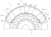
- FIG. 2 is a schematic diagram showing an example of how the thermistor and thermostat are attached to each winding.
- the thermistor 5 and thermostat 6 are fixed to each winding by adhesive.
- the thermistor 5 and thermostat 6 may be fixed to each winding by means of fasteners other than adhesive.
- the electric motor 1 includes a first winding 221a forming a first phase and a second winding 222a forming a second phase different from the first phase.
- the first phase is, for example, a U-phase.
- the second phase is, for example, a V-phase.
- the thermistor 5 is attached to the first winding 221a.
- the thermostat 6 is attached to the second winding 222a.
- the winding to which the thermistor 5 is attached is the first winding 221a.
- the winding to which the thermostat 6 is attached is the second winding 222a.
- the motor 1 further includes one or more first sub-windings 221b forming a first phase and one or more second sub-windings 222b forming a second phase.
- the one or more first sub-windings 221b are one or more windings that have the same phase as the first winding 221a and to which neither a thermistor 5 nor a thermostat 6 is attached.
- the one or more second sub-windings 222b are one or more windings that have the same phase as the second winding 222a and to which neither a thermistor 5 nor a thermostat 6 is attached.
- the one or more first sub-windings 221b together with the first winding 221a, form a row of windings that are continuous in the circumferential direction of the stator core 21.
- the first winding 221a and the one or more first sub-windings 221b are continuously arranged in the circumferential direction of the stator core 21 to form a first row.
- two first sub-windings 221b are arranged side by side in the circumferential direction of the stator core 21 together with the first winding 221a.
- the one or more second secondary windings 222b together with the second winding 222a, form a row of windings that are continuous in the circumferential direction of the stator core 21.
- the second winding 222a and the one or more second secondary windings 222b are continuously arranged in the circumferential direction of the stator core 21 to form a second row.
- two second secondary windings 222b are arranged side by side in the circumferential direction of the stator core 21 together with the second winding 222a.
- the motor 1 further includes a plurality of windings 22 forming a third phase.
- the third phase is, for example, the W phase.
- the plurality of windings 22 forming the third phase form a row of windings that is continuous in the circumferential direction of the stator core 21.
- the thermistor 5 and thermostat 6 are not attached to the plurality of windings 22 forming the third phase.
- the thermostat 6 is connected in series to the thermistor 5.
- the temperature of the first winding 221a and the temperature of the second winding 222a are measured based on the combined resistance of the thermistor 5 and the thermostat 6.
- FIG. 3 is a graph showing an example of the temperature characteristics of thermistor 5 and thermostat 6 attached to first winding 221a and second winding 222a, respectively.
- the curve showing the decrease in resistance value as temperature increases is the line showing the temperature characteristics of thermistor 5.
- the line showing the temperature characteristics of thermostat 6 is drawn so that the resistance is 0 [ ⁇ ] when the temperature is below a certain temperature T [°C] and becomes infinite when the temperature exceeds the certain temperature T [°C].
- a resistance of 0 [ ⁇ ] does not have to be strictly 0 [ ⁇ ], but may be any resistance close to 0 [ ⁇ ].
- the resistance value of thermostat 6 below the certain temperature T [°C] is, for example, the resistance value of copper.
- the value of the combined resistance is the same as the resistance value of the thermistor 5. This is because the resistance value of the thermostat 6 is 0 [ ⁇ ] unless it is infinite. Therefore, when the value of the combined resistance is less than the first reference value R1 [ ⁇ ], the temperature of the first winding 221a can be measured based on the value of the combined resistance. For example, it is possible to measure the temperature of the first winding 221a in real time while the electric motor 1 is running.
- the temperature of the first winding 221a will be equal to or greater than the predetermined temperature T [°C]. In other words, the first winding 221a is overheated. In this case, the supply of power to the motor 1 may be stopped. Also, as described below, an alarm may be output.
- the temperature of the thermostat 6 is equal to or greater than the predetermined temperature T [°C].
- the second winding 222a is overheating.
- the supply of power to the motor 1 may be stopped. Also, as described below, an alarm may be output.
- FIG. 4 is a schematic diagram showing an example of a manner in which the thermistor 5 and the thermostat 6 are attached to the respective windings.
- the electric motor 1 includes a first winding 221a forming a first phase, a second winding 222a forming a second phase different from the first phase, and a third winding 223a forming a third phase different from the first phase and the second phase.
- the first phase is, for example, a U phase.
- the second phase is, for example, a V phase.
- the third phase is, for example, a W phase.
- Thermistor 5 is attached to the second winding 222a.
- the winding to which the thermistor 5 is attached is the second winding 222a.
- Thermostat 6 is attached to the first winding 221a and the third winding 223a.
- the winding to which the thermostat 6 is attached is the first winding 221a and the third winding 223a.
- the motor 1 further includes one or more first sub-windings 221b forming a first phase, one or more second sub-windings 222b forming a second phase, and one or more third sub-windings 223b forming a third phase.
- the one or more first sub-windings 221b are one or more windings that have the same phase as the first winding 221a and to which neither a thermistor 5 nor a thermostat 6 is attached.
- the one or more second sub-windings 222b are one or more windings that have the same phase as the second winding 222a and to which neither a thermistor 5 nor a thermostat 6 is attached.
- the one or more third sub-windings 223b are one or more windings that have the same phase as the third winding 223a and to which neither a thermistor 5 nor a thermostat 6 is attached.
- the one or more first sub-windings 221b together with the first winding 221a, form a row of windings that are continuous in the circumferential direction of the stator core 21.
- the first winding 221a and the one or more first sub-windings 221b are continuously arranged in the circumferential direction of the stator core 21 to form a first row.
- two first sub-windings 221b are arranged side by side in the circumferential direction of the stator core 21 together with the first winding 221a.
- the one or more second secondary windings 222b together with the second winding 222a, form a row of windings that are continuous in the circumferential direction of the stator core 21.
- the second winding 222a and the one or more second secondary windings 222b are continuously arranged in the circumferential direction of the stator core 21 to form a second row.
- two second secondary windings 222b are arranged side by side in the circumferential direction of the stator core 21 together with the second winding 222a.
- the one or more third secondary windings 223b together with the third winding 223a, form a row of windings that are continuous in the circumferential direction of the stator core 21.
- the third winding 223a and the one or more third secondary windings 223b are continuously arranged in the circumferential direction of the stator core 21 to form a third row.
- two third secondary windings 223b are arranged side by side in the circumferential direction of the stator core 21 together with the third winding 223a.
- the two thermostats 6 are connected in series with the thermistor 5.
- the two thermostats 6 are also connected in series with each other.
- the temperatures of the first winding 221a, the second winding 222a, and the third winding 223a are measured based on the combined resistance of the thermistor 5 and the two thermostats 6.
- the value of the combined resistance is the same as the resistance of the thermistor 5. This is because the resistance of the thermostat 6 is 0 [ ⁇ ] unless it is infinite. Therefore, when the value of the combined resistance is less than the first reference value R1 [ ⁇ ], the temperature of the second winding 222a can be measured based on the value of the combined resistance. For example, it is possible to measure the temperature of the second winding 222a in real time while the electric motor 1 is running.
- the temperature of the second winding 222a will be equal to or greater than the predetermined temperature T [°C]. In other words, the second winding 222a is overheated. In this case, the supply of power to the motor 1 may be stopped.
- the temperature of at least one of the two thermostats 6 is equal to or greater than the predetermined temperature T [°C].
- T the predetermined temperature
- FIG. 5 is a schematic diagram showing an example of a manner in which the thermistor 5 and the thermostat 6 are attached to the respective windings.
- the electric motor 1 includes a first winding 221a forming a first phase and a second winding 222a forming a second phase different from the first phase.
- the first phase is, for example, a U-phase.
- the second phase is, for example, a V-phase.
- the thermistor 5 is attached to the first winding 221a.
- the thermostat 6 is attached to the second winding 222a.
- the winding to which the thermistor 5 is attached is the first winding 221a.
- the winding to which the thermostat 6 is attached is the second winding 222a.
- the motor 1 further includes one or more first sub-windings 221b forming a first phase and one or more second sub-windings 222b forming a second phase.
- the one or more first sub-windings 221b are one or more windings that have the same phase as the first winding 221a and to which neither a thermistor 5 nor a thermostat 6 is attached.
- the one or more second sub-windings 222b are one or more windings that have the same phase as the second winding 222a and to which neither a thermistor 5 nor a thermostat 6 is attached.
- the one or more first sub-windings 221b together with the first winding 221a, form a row of windings that are continuous in the circumferential direction of the stator core 21.
- the first winding 221a and the one or more first sub-windings 221b are arranged continuously in the circumferential direction of the stator core 21 to form a first row.
- first winding 221a is arranged in the center of the first row.
- center means that the same number of first sub-windings 221b are arranged on both sides of the first winding 221a in the circumferential direction of the stator core 21.
- the total number of the first winding 221a and the one or more first sub-windings 221b is three, one first sub-winding 221b is arranged on each side of the first winding 221a.
- the number of first sub-windings 221b arranged on both sides of the first winding 221a in the circumferential direction of the stator core 21 does not necessarily have to be strictly the same.
- the first winding 221a may be any one of the two windings closer to the center.
- one first sub-winding 221b is arranged on one side of the first winding 221a, and two first sub-windings 221b are arranged on the other side. This case also falls within the concept of the first winding 221a being arranged in the center of the first row.
- the one or more second sub-windings 222b together with the second winding 222a, form a row of windings that are continuous in the circumferential direction of the stator core 21.
- the second winding 222a and the one or more second sub-windings 222b are arranged continuously in the circumferential direction of the stator core 21 to form a second row.
- the second winding 222a is arranged in the center of the second row.
- center means that the same number of second sub-windings 222b are arranged on both sides of the second winding 222a in the circumferential direction of the stator core 21.
- the number of second sub-windings 222b arranged on both sides of the second winding 222a in the circumferential direction of the stator core 21 does not necessarily have to be strictly the same.
- the second winding 222a may be any one of the two windings closer to the center. This case is also included in the concept that the second winding 222a is arranged in the center of the second row.
- the motor 1 further includes a plurality of windings 22 forming a third phase.
- the third phase is, for example, the W phase.
- the plurality of windings 22 form a row of windings that are continuous in the circumferential direction of the stator core 21.
- the thermistor 5 and thermostat 6 are not attached to the plurality of windings 22 forming the third phase.
- the thermostat 6 is connected in series with the thermistor 5.
- the temperature of the first winding 221a and the temperature of the second winding 222a are measured based on the combined resistance of the thermistor 5 and the thermostat 6.
- the value of the combined resistance is approximately the same as the resistance of thermistor 5. This is because the resistance of thermostat 6 is 0 [ ⁇ ] unless it is infinite. Therefore, when the value of the combined resistance is less than the first reference value R1 [ ⁇ ], the temperature of first winding 221a can be measured based on the value of the combined resistance.
- the temperature of the first winding 221a will be equal to or greater than the predetermined temperature T [°C]. In other words, the first winding 221a is overheated. In this case, the supply of power to the motor 1 may be stopped.
- the first winding 221a to which the thermistor 5 is attached is positioned in the center of the first row. Therefore, if only the winding 22 that constitutes the first phase is overheated, this overheating can be detected more reliably.
- the temperature of the thermostat 6 is equal to or greater than the predetermined temperature T [°C].
- the second winding 222a is overheated. In this case, for example, the supply of power to the motor 1 may be stopped.
- the second winding 222a to which the thermostat 6 is attached is positioned in the center of the second row. Therefore, if only the winding 22 constituting the second phase is overheated, this overheating can be detected more reliably.
- FIG. 6 is a schematic diagram showing an example of a manner in which the thermistor 5 and the thermostat 6 are attached to the respective windings.
- the electric motor 1 includes a first winding 221a forming a first phase, a second winding 222a forming a second phase different from the first phase, and a third winding 223a forming a third phase different from the first phase and the second phase.
- the first phase is, for example, a U phase.
- the second phase is, for example, a V phase.
- the third phase is, for example, a W phase.
- Thermistor 5 is attached to the second winding 222a.
- the winding to which the thermistor 5 is attached is the second winding 222a.
- Thermostat 6 is attached to the first winding 221a and the third winding 223a.
- the winding to which the thermostat 6 is attached is the first winding 221a and the third winding 223a.
- the motor 1 further includes one or more first sub-windings 221b forming a first phase, one or more second sub-windings 222b forming a second phase, and one or more third sub-windings 223b forming a third phase.
- the meaning of the one or more first secondary windings 221b and the one or more second secondary windings 222b is as described above.
- the one or more third secondary windings 223b are one or more windings that have the same phase as the third winding 223a and to which neither thermistor 5 nor thermostat 6 is attached.
- the one or more first sub-windings 221b together with the first winding 221a, form a row of windings that are continuous in the circumferential direction of the stator core 21.
- the first winding 221a and the one or more first sub-windings 221b are continuously arranged in the circumferential direction of the stator core 21 to form a first row.
- the first winding 221a is arranged in the center of the first row.
- the one or more second sub-windings 222b together with the second winding 222a, form a row of windings that are continuous in the circumferential direction of the stator core 21.
- the second winding 222a and the one or more second sub-windings 222b are continuously arranged in the circumferential direction of the stator core 21 to form a second row.
- the second winding 222a is also arranged in the center of the second row.
- the one or more third sub-windings 223b together with the third winding 223a, form a row of windings that are continuous in the circumferential direction of the stator core 21.
- the third winding 223a and the one or more third sub-windings 223b are continuously arranged in the circumferential direction of the stator core 21 to form a third row.
- the third winding 223a is also arranged in the center of the third row.
- center means that the same number of third sub-windings 223b are arranged on both sides of the third winding 223a in the circumferential direction of the stator core 21.
- the number of third sub-windings 223b arranged on both sides of the third winding 223a in the circumferential direction of the stator core 21 does not necessarily have to be strictly the same.
- the third winding 223a may be any one of the two windings 22 closer to the center. This case also falls within the concept of the third winding 223a being arranged in the center of the third row.
- the two thermostats 6 are connected in series with the thermistor 5.
- the two thermostats 6 are also connected in series with each other.
- the temperatures of the first winding 221a, the second winding 222a, and the third winding 223a are measured based on the combined resistance of the thermistor 5 and the two thermostats 6.
- the value of the combined resistance is the same as the resistance of thermistor 5. This is because the resistance of thermostat 6 is 0 [ ⁇ ] unless it is infinite. Therefore, when the value of the combined resistance is less than the first reference value R1 [ ⁇ ], the temperature of second winding 222a can be measured based on the value of the combined resistance.
- the temperature of the second winding 222a will be equal to or greater than the predetermined temperature T [°C]. In other words, the second winding 222a is overheated. In this case, the supply of power to the motor 1 may be stopped.
- the second winding 222a to which the thermistor 5 is attached is positioned in the center of the second row. Therefore, if only the winding 22 constituting the second phase is overheated, this overheating can be detected more reliably.
- the temperature of at least one of the two thermostats 6 is equal to or greater than the predetermined temperature T [°C]. In other words, at least one of the first winding 221a and the third winding 223a is overheated. In this case, the supply of power to the electric motor 1 may be stopped.
- the first winding 221a and the third winding 223a to which the thermostat 6 is attached are disposed in the center of the first row and the third row, respectively. Therefore, if only the winding 22 constituting the first phase or only the winding 22 constituting the third phase is overheated, this can be detected more reliably.
- the control device is, for example, a control device that controls the electric motor 1.
- the electric motor 1 is at least one of the electric motors 1 disclosed in the first to fourth embodiments described above.
- FIG. 7 is a block diagram showing an example of the hardware configuration of a control device.
- the control device 10 is, for example, a numerical control device that controls industrial machinery.
- the control device 10 may be a computer such as a PC (Personal Computer), a server, or a tablet terminal.
- the control device 10 comprises a hardware processor 11, a bus 12, a ROM (Read Only Memory) 13, a RAM (Random Access Memory) 14, a non-volatile memory 15, and an interface 16.
- the hardware processor 11 is a processor that controls the entire control device 10 in accordance with a system program.
- the hardware processor 11 reads the system program stored in the ROM 13 via the bus 12, and performs various processes based on the system program.
- the hardware processor 11 is, for example, a CPU (Central Processing Unit) or an electronic circuit.
- the bus 12 is a communication path that connects each piece of hardware in the control device 10 to each other. Each piece of hardware in the control device 10 exchanges data via the bus 12.
- ROM 13 is a storage device that stores system programs and the like for controlling the entire control device 10.
- ROM 13 is a computer-readable storage medium.
- RAM 14 is a storage device that temporarily stores various data. RAM 14 functions as a working area for the hardware processor 11 to process various data.
- the non-volatile memory 15 is a storage device that retains data even when the control device 10 is turned off and no power is being supplied to the control device 10.
- the non-volatile memory 15 is a computer-readable storage medium.
- the non-volatile memory 15 is composed of, for example, a battery-backed memory or an SSD (Solid State Drive).
- the interface 16 connects the bus 12 to the electric motor 1.
- the control device 10 transmits and receives data to and from the electric motor 1 via the interface 16.
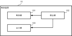
- FIG. 8 is a block diagram showing an example of the functions of the control device 10.
- the control device 10 includes, for example, a control unit 101, a detection unit 102, and an output unit 103.
- the control unit 101, the detection unit 102, and the output unit 103 are realized, for example, by the hardware processor 11 performing calculations using a system program stored in the ROM 13 and various data stored in the non-volatile memory 15.
- the control unit 101 controls the operation of the electric motor 1, for example, based on an operating program stored in a memory unit (not shown).
- the detection unit 102 detects the combined resistance of the thermistor 5 and the thermostat 6.
- the thermistor 5 is attached to a first winding 221a that is wound around the stator core 21 of the motor 1 and forms a first phase, for example.
- the thermostat 6 is attached to a second winding 222a that is wound around the stator core 21 and forms a second phase different from the first phase.
- the thermostat 6 is also connected in series with the thermistor 5.
- the output unit 103 outputs an alarm when the value of the combined resistance detected by the detection unit 102 becomes equal to or greater than a first reference value or equal to or less than a second reference value.
- the output unit 103 outputs the alarm to, for example, a display device (not shown) included in the control device 10.
- the output unit 103 may output the alarm using a rotating light connected to the control device 10.
- the control unit 101 stops the operation of the electric motor 1.
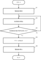
- FIG. 9 is a flowchart showing an example of processing executed by the control device 10.
- the control unit 101 of the control device 10 executes control of the electric motor 1 (step S1).
- the detection unit 102 detects the combined resistance of the thermistor 5 and thermostat 6 (step S2).
- the detection unit 102 determines whether the value of the combined resistance satisfies a predetermined condition (step S3). Specifically, the detection unit 102 determines whether the value of the combined resistance is equal to or greater than a first reference value or equal to or less than a second reference value.
- the detection unit 102 continues to detect the combined resistance.
- step S3 If the combined resistance satisfies the predetermined condition (Yes in step S3), the output unit 103 outputs an alarm (step S4). Furthermore, the control unit 101 stops the operation of the electric motor 1 (step S5), and the process ends.
- the electric motor 1 includes a stator core 21, a first winding 221a wound around the stator core 21 and constituting a first phase, a second winding 222a wound around the stator core 21 and constituting a second phase different from the first phase, a thermistor 5 attached to the first winding 221a, and a thermostat 6 connected in series to the thermistor 5 and attached to the second winding 222a.
- the overheating can be detected. Furthermore, since the thermistor 5 and the thermostat 6 are connected in series, the wiring can be prevented from becoming complicated.
- the motor 1 further includes one or more first sub-windings 221b forming a first phase, where the first winding 221a and the one or more first sub-windings 221b are continuously arranged in the circumferential direction of the stator core 21 to form a first row, and the first winding 221a is arranged in the center of the first row.
- the motor 1 further includes one or more second sub-windings 222b forming a second phase, where the second winding 222a and the one or more second sub-windings 222b are continuously arranged in the circumferential direction of the stator core 21 to form a second row, and the second winding 222a is arranged in the center of the second row.
- the temperature will be highest near the center of the first row.
- the temperature near both ends of the first row will be relatively low due to the influence of the surrounding temperature. Therefore, by arranging the first winding 221a in the center of the first row, if the winding 22 forming the first phase overheats, the overheating can be detected early.
- the second winding 222a in the center of the second row if the winding 22 forming the second phase overheats, the overheating can be detected early.
- the control device 10 also includes a detection unit 102 that detects a combined resistance between the resistance of a thermistor 5 that is wound around the stator core 21 of the electric motor 1 and attached to a first winding 221a that forms a first phase, and the resistance of a thermostat 6 that is wound around the stator core 21 and attached to a second winding 222a that forms a second phase different from the first phase and is connected in series with the thermistor 5, and an output unit 103 that outputs an alarm when the value of the combined resistance detected by the detection unit 102 becomes equal to or greater than a first reference value or equal to or less than a second reference value.
- control device 10 can detect overheating even if only the first winding 221a or the second winding 222a is overheated.
- detection unit 102 can notify the operator at an early stage that it has detected overheating.
- An electric motor comprising: a stator core; a first winding wound around the stator core and constituting a first phase; a second winding wound around the stator core and constituting a second phase different from the first phase; a thermistor attached to the first winding; and a thermostat connected in series to the thermistor and attached to the second winding.
- Appendix [2] the electric motor according to appendix [1], further including one or more first sub-windings forming the first phase, the first winding and the one or more first sub-windings being continuously arranged in a circumferential direction of the stator core to form a first row, and the first winding being arranged in a center of the first row.
- Appendix [3] The electric motor according to appendix [1] or [2], further including one or more second secondary windings forming the second phase, the second winding and the one or more second secondary windings being continuously disposed in a circumferential direction of the stator core to form a second row, and the second winding being disposed in a center of the second row.
- Appendix [4] a control device comprising: a detection unit that detects a combined resistance of a thermistor attached to a first winding wound around a stator core of an electric motor and forming a first phase, and a thermostat that is wound around the stator core and attached to a second winding forming a second phase different from the first phase and is connected in series with the thermistor; and an output unit that outputs an alarm when the value of the combined resistance detected by the detection unit becomes equal to or greater than a first reference value or equal to or less than a second reference value.
Landscapes
- Engineering & Computer Science (AREA)
- Power Engineering (AREA)
- Microelectronics & Electronic Packaging (AREA)
Abstract
Description
図1は、電動機を説明するための図である。電動機1は、例えば、3相交流用電動機である。電動機1は、3相交流用電動機に限らず、単相交流用電動機であってもよい。また、電動機1は、直流用電動機であってもよい。直流用電動機は、例えば、ブラシレスDC(Direct Current)電動機である。なお、以下では、3相交流用電動機を用いて各実施形態を説明する。
図4は、サーミスタ5とサーモスタット6の各巻線への取り付け態様の一例を示す概略図である。
図5は、サーミスタ5とサーモスタット6の各巻線への取り付け態様の一例を示す概略図である。
図6は、サーミスタ5とサーモスタット6の各巻線への取り付け態様の一例を示す概略図である。
次に、電動機1から検出される温度が所定の温度を超えた場合にアラームを出力する制御装置について説明する。制御装置は、例えば、電動機1の制御を行う制御装置である。電動機1は、上述した第1の実施形態~第4の実施形態で開示された電動機1の少なくともいずれかである。
付記[1]
ステータコアと、前記ステータコアに巻回され、第1の相をなす第1の巻線と、前記ステータコアに巻回され、前記第1の相とは異なる第2の相をなす第2の巻線と、前記第1の巻線に取り付けられるサーミスタと、前記サーミスタに直列に接続され、かつ、前記第2の巻線に取り付けられるサーモスタットと、を備える電動機。
付記[2]
前記第1の相をなす1または複数の第1の副巻線をさらに含み、前記第1の巻線および前記1または複数の第1の副巻線は、前記ステータコアの円周方向に連続して配置されて第1の列をなし、前記第1の巻線は、前記第1の列の中央に配置される付記[1]に記載の電動機。
付記[3]
前記第2の相をなす1または複数の第2の副巻線をさらに含み、前記第2の巻線および前記1または複数の第2の副巻線は、前記ステータコアの円周方向に連続して配置されて第2の列をなし、前記第2の巻線は、前記第2の列の中央に配置される付記[1]または[2]に記載の電動機。
付記[4]
電動機のステータコアに巻回されて第1の相をなす第1の巻線に取り付けられるサーミスタの抵抗と、前記ステータコアに巻回されて前記第1の相とは異なる第2の相をなす第2の巻線に取り付けられ、かつ、前記サーミスタと直列に接続されるサーモスタットの抵抗との合成抵抗を検出する検出部と、前記検出部によって検出される前記合成抵抗の値が第1の基準値以上または第2の基準値以下となった場合にアラームを出力する出力部と、を備える制御装置。
2 ステータ
21 ステータコア
211 ヨーク
212 ティース
22 巻線
221a 第1の巻線
221b 第1の副巻線
222a 第2の巻線
222b 第2の副巻線
223a 第3の巻線
223b 第3の副巻線
3 ロータ
31 永久磁石
5 サーミスタ
6 サーモスタット
10 制御装置
11 ハードウェアプロセッサ
12 バス
13 ROM
14 RAM
15 不揮発性メモリ
16 インタフェース
101 制御部
102 検出部
103 出力部
Claims (4)
- ステータコアと、
前記ステータコアに巻回され、第1の相をなす第1の巻線と、
前記ステータコアに巻回され、前記第1の相とは異なる第2の相をなす第2の巻線と、
前記第1の巻線に取り付けられるサーミスタと、
前記サーミスタに直列に接続され、かつ、前記第2の巻線に取り付けられるサーモスタットと、
を備える電動機。 - 前記第1の相をなす1または複数の第1の副巻線をさらに含み、
前記第1の巻線および前記1または複数の第1の副巻線は、前記ステータコアの円周方向に連続して配置されて第1の列をなし、前記第1の巻線は、前記第1の列の中央に配置される請求項1に記載の電動機。 - 前記第2の相をなす1または複数の第2の副巻線をさらに含み、
前記第2の巻線および前記1または複数の第2の副巻線は、前記ステータコアの円周方向に連続して配置されて第2の列をなし、前記第2の巻線は、前記第2の列の中央に配置される請求項1または2に記載の電動機。 - 電動機のステータコアに巻回されて第1の相をなす第1の巻線に取り付けられるサーミスタの抵抗と、前記ステータコアに巻回されて前記第1の相とは異なる第2の相をなす第2の巻線に取り付けられ、かつ、前記サーミスタと直列に接続されるサーモスタットの抵抗との合成抵抗を検出する検出部と、
前記検出部によって検出される前記合成抵抗の値が第1の基準値以上または第2の基準値以下となった場合にアラームを出力する出力部と、
を備える制御装置。
Priority Applications (4)
| Application Number | Priority Date | Filing Date | Title |
|---|---|---|---|
| JP2024555590A JPWO2024075282A1 (ja) | 2022-10-07 | 2022-10-07 | |
| CN202280100591.2A CN119968762A (zh) | 2022-10-07 | 2022-10-07 | 电动机以及控制装置 |
| DE112022007523.6T DE112022007523T5 (de) | 2022-10-07 | 2022-10-07 | Elektromotor und steuervorrichtung |
| PCT/JP2022/037642 WO2024075282A1 (ja) | 2022-10-07 | 2022-10-07 | 電動機および制御装置 |
Applications Claiming Priority (1)
| Application Number | Priority Date | Filing Date | Title |
|---|---|---|---|
| PCT/JP2022/037642 WO2024075282A1 (ja) | 2022-10-07 | 2022-10-07 | 電動機および制御装置 |
Publications (2)
| Publication Number | Publication Date |
|---|---|
| WO2024075282A1 true WO2024075282A1 (ja) | 2024-04-11 |
| WO2024075282A9 WO2024075282A9 (ja) | 2025-02-13 |
Family
ID=90607957
Family Applications (1)
| Application Number | Title | Priority Date | Filing Date |
|---|---|---|---|
| PCT/JP2022/037642 Ceased WO2024075282A1 (ja) | 2022-10-07 | 2022-10-07 | 電動機および制御装置 |
Country Status (4)
| Country | Link |
|---|---|
| JP (1) | JPWO2024075282A1 (ja) |
| CN (1) | CN119968762A (ja) |
| DE (1) | DE112022007523T5 (ja) |
| WO (1) | WO2024075282A1 (ja) |
Citations (4)
| Publication number | Priority date | Publication date | Assignee | Title |
|---|---|---|---|---|
| JP2009050096A (ja) * | 2007-08-21 | 2009-03-05 | Nidec Shibaura Corp | ブラシレスモールドモータ |
| EP2187494A2 (de) * | 2008-11-13 | 2010-05-19 | Kriwan Industrie-Elektronik Gmbh | Schutzeinrichtung für elektrische Motoren |
| US20150338284A1 (en) * | 2014-05-21 | 2015-11-26 | Kriwan Industrie-Elektronik Gmbh | Measurement circuit |
| WO2018003105A1 (ja) * | 2016-06-30 | 2018-01-04 | 株式会社安川電機 | 回転電機及び回転電機の駆動システム |
-
2022
- 2022-10-07 WO PCT/JP2022/037642 patent/WO2024075282A1/ja not_active Ceased
- 2022-10-07 JP JP2024555590A patent/JPWO2024075282A1/ja active Pending
- 2022-10-07 CN CN202280100591.2A patent/CN119968762A/zh active Pending
- 2022-10-07 DE DE112022007523.6T patent/DE112022007523T5/de active Pending
Patent Citations (4)
| Publication number | Priority date | Publication date | Assignee | Title |
|---|---|---|---|---|
| JP2009050096A (ja) * | 2007-08-21 | 2009-03-05 | Nidec Shibaura Corp | ブラシレスモールドモータ |
| EP2187494A2 (de) * | 2008-11-13 | 2010-05-19 | Kriwan Industrie-Elektronik Gmbh | Schutzeinrichtung für elektrische Motoren |
| US20150338284A1 (en) * | 2014-05-21 | 2015-11-26 | Kriwan Industrie-Elektronik Gmbh | Measurement circuit |
| WO2018003105A1 (ja) * | 2016-06-30 | 2018-01-04 | 株式会社安川電機 | 回転電機及び回転電機の駆動システム |
Also Published As
| Publication number | Publication date |
|---|---|
| WO2024075282A9 (ja) | 2025-02-13 |
| DE112022007523T5 (de) | 2025-05-15 |
| JPWO2024075282A1 (ja) | 2024-04-11 |
| CN119968762A (zh) | 2025-05-09 |
Similar Documents
| Publication | Publication Date | Title |
|---|---|---|
| CN108778896A (zh) | 电动机控制系统及具备电动机控制系统的电动助力转向装置 | |
| JP6122876B2 (ja) | 温度に基づき電気機械の電力供給を制御するためのシステムおよび方法 | |
| JP6642608B2 (ja) | モータ装置 | |
| JP6096718B2 (ja) | 複数のptcサーミスタを備えた電動機の過熱検出装置 | |
| JP4154639B2 (ja) | モータスタータの温度保護制御方法及び装置 | |
| JP6582488B2 (ja) | 電動機システム | |
| CN108604849B (zh) | 发电机冷却方法 | |
| CN115118200A (zh) | 控制装置及控制方法 | |
| CN115103985B (zh) | 空调装置 | |
| JP2014508493A (ja) | 密閉型冷却コンプレッサのデュアル電圧誘導電動機のための巻線スイッチング回路と熱保護 | |
| JP2014165969A (ja) | モータ判別装置 | |
| EP1037355B1 (en) | Thermal compensation control for a motor starter | |
| US9742246B2 (en) | Multiple speed motor with thermal overload protection | |
| WO2024075282A1 (ja) | 電動機および制御装置 | |
| JP4539237B2 (ja) | インバータ装置 | |
| JPH05276720A (ja) | 電動機 | |
| CN101245944A (zh) | 空气调节器及其控制方法 | |
| JP3004220B2 (ja) | 洗濯機の洗濯モータ過熱防止装置及びその制御方法 | |
| JP2006158089A (ja) | モータ制御装置 | |
| KR20140034228A (ko) | 전기 충전기의 입력 전압 제어를 위한 방법 및 시스템 | |
| JP5997642B2 (ja) | シリーズハイブリッドシステム | |
| KR100202598B1 (ko) | 무정류자 전동기 과열보호장치 | |
| US20220137138A1 (en) | Device for diagnosing turn-short fault of induction motor and method thereof | |
| JP6544387B2 (ja) | 電力変換装置 | |
| CN121618386A (zh) | 一种家用电器 |
Legal Events
| Date | Code | Title | Description |
|---|---|---|---|
| 121 | Ep: the epo has been informed by wipo that ep was designated in this application |
Ref document number: 22961468 Country of ref document: EP Kind code of ref document: A1 |
|
| WWE | Wipo information: entry into national phase |
Ref document number: 2024555590 Country of ref document: JP |
|
| WWE | Wipo information: entry into national phase |
Ref document number: 112022007523 Country of ref document: DE |
|
| WWE | Wipo information: entry into national phase |
Ref document number: 202280100591.2 Country of ref document: CN |
|
| WWP | Wipo information: published in national office |
Ref document number: 202280100591.2 Country of ref document: CN |
|
| WWP | Wipo information: published in national office |
Ref document number: 112022007523 Country of ref document: DE |
|
| 122 | Ep: pct application non-entry in european phase |
Ref document number: 22961468 Country of ref document: EP Kind code of ref document: A1 |