EP1037355B1 - Thermal compensation control for a motor starter - Google Patents
Thermal compensation control for a motor starter Download PDFInfo
- Publication number
- EP1037355B1 EP1037355B1 EP00105030A EP00105030A EP1037355B1 EP 1037355 B1 EP1037355 B1 EP 1037355B1 EP 00105030 A EP00105030 A EP 00105030A EP 00105030 A EP00105030 A EP 00105030A EP 1037355 B1 EP1037355 B1 EP 1037355B1
- Authority
- EP
- European Patent Office
- Prior art keywords
- temperature
- motor
- pole
- starter
- ambient
- Prior art date
- Legal status (The legal status is an assumption and is not a legal conclusion. Google has not performed a legal analysis and makes no representation as to the accuracy of the status listed.)
- Expired - Lifetime
Links
Images

Classifications
-
- H—ELECTRICITY
- H02—GENERATION; CONVERSION OR DISTRIBUTION OF ELECTRIC POWER
- H02H—EMERGENCY PROTECTIVE CIRCUIT ARRANGEMENTS
- H02H7/00—Emergency protective circuit arrangements specially adapted for specific types of electric machines or apparatus or for sectionalised protection of cable or line systems, and effecting automatic switching in the event of an undesired change from normal working conditions
- H02H7/08—Emergency protective circuit arrangements specially adapted for specific types of electric machines or apparatus or for sectionalised protection of cable or line systems, and effecting automatic switching in the event of an undesired change from normal working conditions for dynamo-electric motors
- H02H7/085—Emergency protective circuit arrangements specially adapted for specific types of electric machines or apparatus or for sectionalised protection of cable or line systems, and effecting automatic switching in the event of an undesired change from normal working conditions for dynamo-electric motors against excessive load
- H02H7/0852—Emergency protective circuit arrangements specially adapted for specific types of electric machines or apparatus or for sectionalised protection of cable or line systems, and effecting automatic switching in the event of an undesired change from normal working conditions for dynamo-electric motors against excessive load directly responsive to abnormal temperature by using a temperature sensor
-
- H—ELECTRICITY
- H02—GENERATION; CONVERSION OR DISTRIBUTION OF ELECTRIC POWER
- H02H—EMERGENCY PROTECTIVE CIRCUIT ARRANGEMENTS
- H02H7/00—Emergency protective circuit arrangements specially adapted for specific types of electric machines or apparatus or for sectionalised protection of cable or line systems, and effecting automatic switching in the event of an undesired change from normal working conditions
- H02H7/08—Emergency protective circuit arrangements specially adapted for specific types of electric machines or apparatus or for sectionalised protection of cable or line systems, and effecting automatic switching in the event of an undesired change from normal working conditions for dynamo-electric motors
- H02H7/0816—Emergency protective circuit arrangements specially adapted for specific types of electric machines or apparatus or for sectionalised protection of cable or line systems, and effecting automatic switching in the event of an undesired change from normal working conditions for dynamo-electric motors concerning the starting sequence, e.g. limiting the number of starts per time unit, monitoring speed during starting
-
- H—ELECTRICITY
- H02—GENERATION; CONVERSION OR DISTRIBUTION OF ELECTRIC POWER
- H02P—CONTROL OR REGULATION OF ELECTRIC MOTORS, ELECTRIC GENERATORS OR DYNAMO-ELECTRIC CONVERTERS; CONTROLLING TRANSFORMERS, REACTORS OR CHOKE COILS
- H02P29/00—Arrangements for regulating or controlling electric motors, appropriate for both AC and DC motors
- H02P29/60—Controlling or determining the temperature of the motor or of the drive
- H02P29/68—Controlling or determining the temperature of the motor or of the drive based on the temperature of a drive component or a semiconductor component
-
- H—ELECTRICITY
- H02—GENERATION; CONVERSION OR DISTRIBUTION OF ELECTRIC POWER
- H02M—APPARATUS FOR CONVERSION BETWEEN AC AND AC, BETWEEN AC AND DC, OR BETWEEN DC AND DC, AND FOR USE WITH MAINS OR SIMILAR POWER SUPPLY SYSTEMS; CONVERSION OF DC OR AC INPUT POWER INTO SURGE OUTPUT POWER; CONTROL OR REGULATION THEREOF
- H02M1/00—Details of apparatus for conversion
- H02M1/32—Means for protecting converters other than automatic disconnection
- H02M1/327—Means for protecting converters other than automatic disconnection against abnormal temperatures
Definitions
- the present invention relates generally to control systems for motor starters, and more particularly to a method and apparatus to compensate a motor starter for increases in temperature.
- thermal protection Many electrical devices use one form or another for thermal protection.
- One of the most common forms of temperature protection includes the use of thermistors, which are heat sensitive resistors that change resistive value with temperature change.
- the thermistor is connected to an electronic monitoring circuit which is set to react to a predetermined resistance value. When that resistance value is reached, the electronic monitoring circuit disconnects, or connects, the temperature protection circuits, which then turn the device off.
- Most electrical devices use a single thermistor for protection. Therefore, the level of protection provided is solely dependent on the location of that single thermistor. In other words, the thermal protection in reality protects only one small portion of the device. In larger devices, many components can be damaged before the thermal protection turns off the device.
- thermal protection is the use of a bimetallic element or disk mounted within the device to open or close a circuit.
- Such devices change shape with heat due to a differential thermal expansion between the two metals that form the physical configuration.
- This form of thermal protection requires calibration by hand-bending or tweaking for each particular device. Further, accuracy is suspect after field adjustments are made and such bi-metal devices typically require invasive connections between components, thereby reducing manufacturability, increasing the cost of the component, and increasing the overall size of the electrical equipment.
- An electrical device with thermal compensation adjusts the starting characteristics of the controller to compensate for the additional ambient temperature.
- This compensation adjusts or increases the output of the device to compensate for the increasing internal resistance of the device caused by heating.
- temperature compensation requires the use of mechanical components, such as the aforementioned bimetallic elements to sense the temperature and adjust the output accordingly. Since thermal compensation ranges are relatively small, several device configurations are required in order to cover an entire product line. Further, thermal compensation adds additional cost to the manufacturing of the device because of the additional components.
- the present invention provides a motor starter thermal compensation and protection control that solves the aforementioned problems without adding significant cost to the overall system.
- a motor starter thermal compensation and protection control includes an ambient temperature sensor to sense ambient temperature and provide an ambient temperature signal indicative of the ambient temperature of a motor starter, and at least one pole temperature sensor in thermal communication with an electrically conducting bus in the motor starter that produces a pole temperature signal indicative of a temperature of the electrically conducting bus.
- a processing unit is connected to the ambient temperature sensor and the at least one pole temperature sensor and is programmed to periodically acquire the ambient and pole temperature signals to determine an operating temperature of the motor starter, and monitor any changes in the operating temperature of the motor based on the periodic acquisitions of the ambient and pole temperature signals. The output of the motor starter is then adjusted based on the change in operating temperature so that the output of the electrical device is constant as the operating temperatures increase. This avoids the need of the electrical rating on the device to be sized larger than is required to compensate for the additional ambient heat in order to operate at the rated load.
- a method of thermally protecting a motor and motor starter includes the steps of periodically monitoring an ambient temperature and a pole temperature of each pole in a motor starter and recording the periodically monitored ambient and pole temperatures. The process next includes comparing present ambient and pole temperatures to previously recorded ambient and pole temperatures and preventing a motor from starting if the temperature comparison reaches a maximum parameter and an FLA adjustment is at a motor limit.
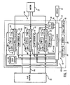
- Fig. 1 is a block diagram of a motor starter thermal protection and compensation control 10 according to the present invention incorporated into a motor starter 12 controlling a motor 14 connected to a power source 15.
- Control 10 includes a central processing unit 28, such as a microprocessor, a microcontroller, a PLC, or any other device for electrical signal processing.
- the motor starter thermal protection control 10 controls the function of the motor starter 12 based on the operating temperatures of the device 12, the ambient, and the motor 14, together with look-up tables stored in memory 29.
- the control 10 of the present invention is shown in a three-phase motor starter application.
- the motor starter 12 relays power from a three-phase source 15 to the motor 14, in part by controlling coils 16, 18, and 20, and in part by controlling a pair of SCRs (not shown) that are typically clamped between two conducting bus bars, which is shown in block diagram form as pole A 22, pole B 24, and pole C 26.
- the microprocessor 28 of the motor starter thermal protection control 10 receives input signals from a number of temperature sensors.
- a temperature sensor 30, 32, 34 is located on each power pole A, B, C. That is, temperature sensor 30 is in thermal communication with power pole 22, temperature sensor 32 is in thermal communication with power pole 24, and temperature sensor 34 is in thermal communication with power pole 26.
- An ambient temperature sensor 36 is also located within the motor starter 12 and connected to the microprocessor 28. In a preferred embodiment, the ambient temperature sensor 36 is located in a cover assembly between poles A and B or between poles B and C to sense the ambient temperature across the poles and within the housing enclosing motor starter 12.
- the microprocessor 28 is also capable of receiving at least one input 38, such as a dip-switch, that can override a temperature protection control to prevent the motor from shutting down when a fault is detected.
- the control can indicate and display the fault on fault display 40.
- the override feature is typically only used in critical processes where the motor can be sacrificed in order to keep the process functioning.
- the motor starter 12 also includes heat sinks 42, 44, and 46 mounted to each power pole, 22, 24, and 26, respectively.
- Each power pole 22, 24, and 26 also has an associated fan 48, 50 and 52, respectively, to draw air into the load side 54 of the motor starter 12, move the air across each heat sink 42, 44 and 46, and discharge the air out a line side 56 of the motor starter 12.
- the microprocessor 28 is connected to a fan driver 58, which in turn drives the fans 48, 50 and 52.
- the microprocessor 28 also has output control lines 60 for controlling the coils 16, 18, and 20 as well as output control line 62 connected to control the SCRs of each pole 22, 24 and 26.
- the motor starter 12 is also connectable to a display device 13 with external connection so that the display 13 can be mounted to the motor starter 12 or remotely.
- the display device 13 is connected to the processor 28 and is used to display a time to a next motor start after the thermal protection control has been activated, as will be further described with reference to Fig. 2 .
- the fault display 40 is typically simply a warning light
- the display device 13 shows a calculated time until the next start will be allowed, preferably as a digital read-out.
- the microprocessor is programmed, upon a start command 64, to read the temperatures in the motor starter prior to start-up of the motor at 66.
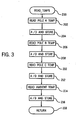
- the Read_Temps is a subroutine and is called a number of times in the main algorithm of Fig. 2 , and will now be described with reference to Fig. 3 .
- the microprocessor first reads the temperature of pole A 202 from the first temperature sensor 30, and after converting the analog signal to a digital signal, the result is stored in memory 204.
- the temperature of pole B 206 is then read and converted from an analog signal to a digital signal, and the result is stored in memory at 208.
- the third temperature sensor 34 is read to acquire the temperature of pole C 210 and then stored as a digital value 212.
- the ambient temperature is read at 214 by sensing ambient sensor 36, the signal is converted and stored at 216, and the Read_Temps subroutine returns 218 to the main algorithm of Fig. 2 .
- the thermal protection control of the present invention relinquishes control of the motor starter to a main control, which is not a subject of this invention.
- the temperatures of the power poles and the ambient are read at 72, and stored as initial start-up parameters 74.
- the processor uses the ambient temperature signals generated by the ambient temperature sensor 36 to model a profile of the external temperature 76.
- the ambient temperature signal is also used together with the pole temperature signals to model the starter temperature 78 and the motor temperature 80, the results of which are stored in memory 29 in the form of a look-up table.
- the motor temperature model 80 includes a cool down profile which is acquired after the motor is shut down and the temperatures are read periodically during a normal cool down cycle.
- the external ambient model is a function of the geographical region temperatures, the building/zone location and the work day calendar. These are the preferred parameters, but other such factors can also be used in determining the external ambient model.
- the starter temperature model is a function of the three pole temperature sensors 30, 32, and 34, together with the specifications such as the frame size of the starter, the FLA (full load amperage) rating, FLA duration, starts required per hour and the duration of the starts per hour. Additionally, the lock rotor count (LRC) of the motor and the LRC duration of the motor can be factored into the starter temperature model as well as the trip class and gage of wire used.
- the motor cool down profile includes much of the same data as the starter, such as FLA and FLA duration, starts per hour, starts per hour duration, LRC and LRC duration, trip class and gage used. It also includes the specific location of the motor, if different from the starter, including geographic region and/or zone or location in the building and the time of day the motor is operational.
- the motor manufacturing specifications are also used in the cool down model include motor service factor, motor horsepower, and motor frame size.
- a temperature comparison module 82 the temperature of the starter components and the load are used to determine the current temperature of the overall starter system wherein the rise in temperature can be monitored by the system.
- the processor can next determine if the motor start ampacity is adequate 84 based on the present operating temperatures.
- the last successful start parameters are then recalled from memory 86.
- the start parameters include the start time, the start temperature, and the start current.
- the processor determines whether it is safe to start the motor 88 when considering the data from the last successful start and the ampacity needed for a current start. If it is determined that the starter can start the motor 88, 90, the start is enabled 92.
- the processor determines that the ampacity is not adequate for another start, 94, the FLA of the device is increased 96 to compensate for ampacity loss due to an increase in ambient temperature.
- the processor delays the start to allow cool down 106 and sets the thermal fault flag 110, and then calculates and displays the time for adequate cool down to allow a next start 112. Temperatures are then read 114, and the process cycles through the modeling steps 76, 78, and 80, and the comparison steps 82, 84, until a start is enabled 92. Once the start is enabled 92, the processor checks to see if the starter has received a run/start command 100, and if not, it continues to cycle through another sequence of the process. If a run/start command is received 100, 102, the motor is allowed to start 70 and the temperatures are read at 72, and the process begins anew.
- the invention includes a method of thermally protecting a motor and a motor starter having the steps of periodically monitoring an ambient temperature and a pole temperature of each pole in a motor starter and recording the periodically monitored ambient and pole temperatures.
- the process includes comparing present ambient and pole temperatures to previously recorded ambient and pole temperatures and preventing a motor start if the temperature comparison reaches a maximum parameter and FLA adjustment is at a motor limit.
- the method further includes the steps of tracking motor cool down by periodically monitoring the ambient temperature and the pole temperature during the cool down and modeling external ambient starter temperature and motor temperature.
- the method includes increasing FLA adjustment if an ampacity limit of the motor is not exceeded. If the ampacity limit is exceeded, the motor is prevented from starting, and the method includes displaying a time needed to cool down until a start is permitted.
Description
- The present invention relates generally to control systems for motor starters, and more particularly to a method and apparatus to compensate a motor starter for increases in temperature.
- Many electrical devices use one form or another for thermal protection. One of the most common forms of temperature protection includes the use of thermistors, which are heat sensitive resistors that change resistive value with temperature change. Typically, the thermistor is connected to an electronic monitoring circuit which is set to react to a predetermined resistance value. When that resistance value is reached, the electronic monitoring circuit disconnects, or connects, the temperature protection circuits, which then turn the device off. Most electrical devices use a single thermistor for protection. Therefore, the level of protection provided is solely dependent on the location of that single thermistor. In other words, the thermal protection in reality protects only one small portion of the device. In larger devices, many components can be damaged before the thermal protection turns off the device. Another problem with such systems is that they provide little warning or assistance in diagnosing the cause of shutting down the device. Further, in some applications or processes, it is critical that the electrical device not be shutdown. In such processes, it would be desirable to have some indication of an overheating condition while keeping the process running.
- Another common method of thermal protection is the use of a bimetallic element or disk mounted within the device to open or close a circuit. Such devices change shape with heat due to a differential thermal expansion between the two metals that form the physical configuration. As the device changes shape, it exerts a physical force on a switch, or on a set of contacts, to change the state of an electrical circuit. That is, a normally opened circuit, for example, will close to activate a temperature protection circuit when the bi-metal strip deforms to a deflection point that corresponds to a temperature indicating an overheating condition. This form of thermal protection requires calibration by hand-bending or tweaking for each particular device. Further, accuracy is suspect after field adjustments are made and such bi-metal devices typically require invasive connections between components, thereby reducing manufacturability, increasing the cost of the component, and increasing the overall size of the electrical equipment.
- An electrical device with thermal compensation adjusts the starting characteristics of the controller to compensate for the additional ambient temperature. This compensation adjusts or increases the output of the device to compensate for the increasing internal resistance of the device caused by heating. Typically, such temperature compensation requires the use of mechanical components, such as the aforementioned bimetallic elements to sense the temperature and adjust the output accordingly. Since thermal compensation ranges are relatively small, several device configurations are required in order to cover an entire product line. Further, thermal compensation adds additional cost to the manufacturing of the device because of the additional components.
- It would be desirable to have a thermal compensation and protection scheme that eliminates the need of these additional components to avoid the need for having variations of the product for different temperature ranges.
- The present invention provides a motor starter thermal compensation and protection control that solves the aforementioned problems without adding significant cost to the overall system.
- A motor starter thermal compensation and protection control, according to the present invention, includes an ambient temperature sensor to sense ambient temperature and provide an ambient temperature signal indicative of the ambient temperature of a motor starter, and at least one pole temperature sensor in thermal communication with an electrically conducting bus in the motor starter that produces a pole temperature signal indicative of a temperature of the electrically conducting bus. A processing unit is connected to the ambient temperature sensor and the at least one pole temperature sensor and is programmed to periodically acquire the ambient and pole temperature signals to determine an operating temperature of the motor starter, and monitor any changes in the operating temperature of the motor based on the periodic acquisitions of the ambient and pole temperature signals. The output of the motor starter is then adjusted based on the change in operating temperature so that the output of the electrical device is constant as the operating temperatures increase. This avoids the need of the electrical rating on the device to be sized larger than is required to compensate for the additional ambient heat in order to operate at the rated load.
- In accordance with yet another aspect of the invention, a method of thermally protecting a motor and motor starter includes the steps of periodically monitoring an ambient temperature and a pole temperature of each pole in a motor starter and recording the periodically monitored ambient and pole temperatures. The process next includes comparing present ambient and pole temperatures to previously recorded ambient and pole temperatures and preventing a motor from starting if the temperature comparison reaches a maximum parameter and an FLA adjustment is at a motor limit.
- Various other features, objects and advantages of the present invention will be made apparent from the following detailed description and the drawings.
- The drawings illustrate the best mode presently contemplated for carrying out the invention.
- In the drawings:
-
Fig. 1 is a block diagram of a motor connected to a three-phase source through a motor starter incorporating the present invention. -
Fig. 2 is a flow chart of the software as programmed in the microprocessor ofFig. 1 . -
Fig. 3 is a flow chart subroutine as called for in the flow chart ofFig. 2 . -
Fig. 1 is a block diagram of a motor starter thermal protection andcompensation control 10 according to the present invention incorporated into amotor starter 12 controlling amotor 14 connected to apower source 15.Control 10 includes acentral processing unit 28, such as a microprocessor, a microcontroller, a PLC, or any other device for electrical signal processing. The motor starterthermal protection control 10 controls the function of themotor starter 12 based on the operating temperatures of thedevice 12, the ambient, and themotor 14, together with look-up tables stored inmemory 29. - As shown in
Fig. 1 , thecontrol 10 of the present invention is shown in a three-phase motor starter application. In a manner that is known, themotor starter 12 relays power from a three-phase source 15 to themotor 14, in part by controllingcoils pole A 22,pole B 24, andpole C 26. - The
microprocessor 28 of the motor starterthermal protection control 10 receives input signals from a number of temperature sensors. In a preferred embodiment, atemperature sensor temperature sensor 30 is in thermal communication withpower pole 22,temperature sensor 32 is in thermal communication withpower pole 24, andtemperature sensor 34 is in thermal communication withpower pole 26. Anambient temperature sensor 36 is also located within themotor starter 12 and connected to themicroprocessor 28. In a preferred embodiment, theambient temperature sensor 36 is located in a cover assembly between poles A and B or between poles B and C to sense the ambient temperature across the poles and within the housing enclosingmotor starter 12. - The
microprocessor 28 is also capable of receiving at least oneinput 38, such as a dip-switch, that can override a temperature protection control to prevent the motor from shutting down when a fault is detected. The control can indicate and display the fault onfault display 40. The override feature is typically only used in critical processes where the motor can be sacrificed in order to keep the process functioning. - The
motor starter 12 also includesheat sinks power pole fan load side 54 of themotor starter 12, move the air across eachheat sink line side 56 of themotor starter 12. Themicroprocessor 28 is connected to afan driver 58, which in turn drives thefans microprocessor 28 also hasoutput control lines 60 for controlling thecoils output control line 62 connected to control the SCRs of eachpole - The
motor starter 12 is also connectable to adisplay device 13 with external connection so that thedisplay 13 can be mounted to themotor starter 12 or remotely. Internally, thedisplay device 13 is connected to theprocessor 28 and is used to display a time to a next motor start after the thermal protection control has been activated, as will be further described with reference toFig. 2 . Where thefault display 40 is typically simply a warning light, thedisplay device 13 shows a calculated time until the next start will be allowed, preferably as a digital read-out. - The operation of the control will now be described with reference to
Figs. 2-3 . Referring toFig. 2 , the microprocessor is programmed, upon astart command 64, to read the temperatures in the motor starter prior to start-up of the motor at 66. The Read_Temps is a subroutine and is called a number of times in the main algorithm ofFig. 2 , and will now be described with reference toFig. 3 . - As shown in
Fig. 3 , when theRead_Temps subroutine 200 is called, the microprocessor first reads the temperature ofpole A 202 from thefirst temperature sensor 30, and after converting the analog signal to a digital signal, the result is stored inmemory 204. The temperature ofpole B 206 is then read and converted from an analog signal to a digital signal, and the result is stored in memory at 208. Thethird temperature sensor 34 is read to acquire the temperature ofpole C 210 and then stored as adigital value 212. The ambient temperature is read at 214 by sensingambient sensor 36, the signal is converted and stored at 216, and the Read_Temps subroutine returns 218 to the main algorithm ofFig. 2 . - Referring back to
Fig. 2 , after theRead_Temps 200 algorithm is complete at 66, the initial values are saved at 68 and the motor is allowed to start 70. That is, the thermal protection control of the present invention relinquishes control of the motor starter to a main control, which is not a subject of this invention. - Once the motor is running, the temperatures of the power poles and the ambient are read at 72, and stored as initial start-up
parameters 74. The processor uses the ambient temperature signals generated by theambient temperature sensor 36 to model a profile of theexternal temperature 76. The ambient temperature signal is also used together with the pole temperature signals to model thestarter temperature 78 and themotor temperature 80, the results of which are stored inmemory 29 in the form of a look-up table. Themotor temperature model 80 includes a cool down profile which is acquired after the motor is shut down and the temperatures are read periodically during a normal cool down cycle. - The external ambient model is a function of the geographical region temperatures, the building/zone location and the work day calendar. These are the preferred parameters, but other such factors can also be used in determining the external ambient model. The starter temperature model is a function of the three
pole temperature sensors - Referring back to
Fig. 2 , in atemperature comparison module 82, the temperature of the starter components and the load are used to determine the current temperature of the overall starter system wherein the rise in temperature can be monitored by the system. Once the system temperature has been determined, the processor can next determine if the motor start ampacity is adequate 84 based on the present operating temperatures. The last successful start parameters are then recalled frommemory 86. The start parameters include the start time, the start temperature, and the start current. The processor then determines whether it is safe to start themotor 88 when considering the data from the last successful start and the ampacity needed for a current start. If it is determined that the starter can start themotor - However, if the processor determines that the ampacity is not adequate for another start, 94, the FLA of the device is increased 96 to compensate for ampacity loss due to an increase in ambient temperature.
- The processor then checks to ensure that the FLA ampacity of the starter does not exceed the motor=s capabilities at 98. If the ampacity required does not exceed the
device capabilities 100, the start is enabled 92. - If the start will exceed this threshold, the processor delays the start to allow cool down 106 and sets the
thermal fault flag 110, and then calculates and displays the time for adequate cool down to allow anext start 112. Temperatures are then read 114, and the process cycles through the modeling steps 76, 78, and 80, and the comparison steps 82, 84, until a start is enabled 92. Once the start is enabled 92, the processor checks to see if the starter has received a run/start command 100, and if not, it continues to cycle through another sequence of the process. If a run/start command is received 100, 102, the motor is allowed to start 70 and the temperatures are read at 72, and the process begins anew. - Accordingly, the invention includes a method of thermally protecting a motor and a motor starter having the steps of periodically monitoring an ambient temperature and a pole temperature of each pole in a motor starter and recording the periodically monitored ambient and pole temperatures. The process includes comparing present ambient and pole temperatures to previously recorded ambient and pole temperatures and preventing a motor start if the temperature comparison reaches a maximum parameter and FLA adjustment is at a motor limit.
- The method further includes the steps of tracking motor cool down by periodically monitoring the ambient temperature and the pole temperature during the cool down and modeling external ambient starter temperature and motor temperature.
- The method includes increasing FLA adjustment if an ampacity limit of the motor is not exceeded. If the ampacity limit is exceeded, the motor is prevented from starting, and the method includes displaying a time needed to cool down until a start is permitted.
Claims (13)
- A motor starter thermal compensation control (10, 64) comprising:an ambient temperature sensor (36) to sense ambient temperature and provide an ambient temperature signal indicative of the ambient temperature about a motor starter (12);at least one pole temperature sensor (30) in thermal communication with an electrically conducting bus (22) in the motor starter (12) that produces a pole temperature signal indicative of a temperature of the electrically conducting bus (22);a processing unit (28) connected to the ambient temperature sensor (36) and the at least one pole temperature sensor (30), the processing unit (28) programmed to:periodically acquire (72, 114) the ambient temperature signal and the pole temperature signal to determine an operating temperature of the motor starter (12);monitor change in the operating temperature (82) based on the periodic acquisitions of the ambient and pole temperature signals; and;adjust an output (96) of the motor starter (12) based on the change in the operating temperature.
- The control (10, 64) of claim 1 further comprising a memory unit (29) having at least one look-up table to store temperature data.
- The control (10, 64) of claim 2 wherein the at least one look-up table includes temperature data for at least one of a motor (14), a motor starter (12), and an ambient condition.
- The control (10, 64) of claim 1 wherein the processing unit is further programmed to compare motor starter temperature (78, 82) and load temperature (80, 82), determine an adequacy of a motor start ampacity (88), and adjust a motor full load amperage (96) if the motor start ampacity (88) is not adequate (94).
- The control (10, 64) of claim 1 wherein the processing unit is further programmed to adjust a motor full load amperage (96) to compensate for ampacity lost due to increase in at least one of ambient temperature, motor temperature, and starter temperature.
- The control (10, 64) of claim 1 wherein the processing unit is further programmed to ensure the motor full load amperage does not exceed motor limits (98).
- The control (10, 64) of claim 1 further comprising at least one display device (13, 40) connected to the processing unit (28) to display at least one of an external warning indicative of an excess thermal condition and a time needed to cool down to a next start.
- The control of claim 1 further comprising:a motor starter (12) having three power poles (22, 24, 26), each power pole having a heat sink (42, 44, 46) thereon and a fan (48, 50, 52) in thermal communication with the heat sink (42, 44, 46);three pole temperature sensors (30, 32, 34), each sensor in thermal communication with a power pole (22, 24, 26) of the motor starter (12) and producing first, second, and third pole temperature signals; andwherein the processing unit (28) is further programmed to:model an external ambient temperature (76);model a starter temperature (78);model a motor temperature (80);perform a temperature comparison (82);perform a motor ampacity comparison (84); andensure a safe motor start condition (88) based on previous start parameters (86).
- The control (10, 64) of claim 1 wherein the processing unit (28) is further programmed to:track motor cool down by periodically reading the ambient temperature signal and the pole temperature signal (72) and create a motor temperature model (80);create an ambient temperature profile model (76) and a pole temperature profile model (76) based on the ambient temperature signals and the pole temperature signals read (114) during motor cool down;compare (82) the ambient temperature profile model (76) and the pole temperature profile model (76); andproduce a maintenance indication (110) if one or both of the ambient temperature profile model (76) and the pole temperature profile model (76) exceed a safe start condition (88).
- A method of thermally protecting a motor (14) and compensating a motor starter (12) comprising the steps of:periodically monitoring (72, 114) an ambient temperature and a pole temperature of each pole in a motor starter (12);recording the periodically monitored ambient and pole temperatures (74);comparing present ambient and pole temperatures to previously recorded ambient and pole temperatures (82, 86); andpreventing a motor start (106) if the temperature comparison reaches a maximum safe parameter (94) and an full load amperage adjustment is at a motor limit (108).
- The method of clam 10 further comprising the steps of:tracking motor cool down by periodically monitoring the ambient temperature and the pole temperature (114) during the motor cool down (106); andmodeling external ambient temperature (76), starter temperature (78), and motor temperature (80) based on the tracking.
- The method of claim 10 further comprising the step of increasing full load amperage adjustment (96) if an ampacity limit of the motor (14) is not exceeded (100).
- The method of claim 10 further comprising the step of displaying a time (112) needed to cool down until a next start is permitted (88, 90).
Priority Applications (1)
| Application Number | Priority Date | Filing Date | Title |
|---|---|---|---|
| EP11006963.0A EP2395621B1 (en) | 1999-03-12 | 2000-03-09 | Thermal compensation control for a motor starter |
Applications Claiming Priority (2)
| Application Number | Priority Date | Filing Date | Title |
|---|---|---|---|
| US12422099P | 1999-03-12 | 1999-03-12 | |
| US124220P | 1999-03-12 |
Related Child Applications (1)
| Application Number | Title | Priority Date | Filing Date |
|---|---|---|---|
| EP11006963.0 Division-Into | 2011-08-25 |
Publications (3)
| Publication Number | Publication Date |
|---|---|
| EP1037355A2 EP1037355A2 (en) | 2000-09-20 |
| EP1037355A3 EP1037355A3 (en) | 2003-01-22 |
| EP1037355B1 true EP1037355B1 (en) | 2012-04-18 |
Family
ID=22413547
Family Applications (2)
| Application Number | Title | Priority Date | Filing Date |
|---|---|---|---|
| EP00105030A Expired - Lifetime EP1037355B1 (en) | 1999-03-12 | 2000-03-09 | Thermal compensation control for a motor starter |
| EP11006963.0A Expired - Lifetime EP2395621B1 (en) | 1999-03-12 | 2000-03-09 | Thermal compensation control for a motor starter |
Family Applications After (1)
| Application Number | Title | Priority Date | Filing Date |
|---|---|---|---|
| EP11006963.0A Expired - Lifetime EP2395621B1 (en) | 1999-03-12 | 2000-03-09 | Thermal compensation control for a motor starter |
Country Status (5)
| Country | Link |
|---|---|
| US (1) | US6297607B1 (en) |
| EP (2) | EP1037355B1 (en) |
| JP (1) | JP2000278975A (en) |
| CN (1) | CN1201473C (en) |
| BR (1) | BR0001147A (en) |
Families Citing this family (14)
| Publication number | Priority date | Publication date | Assignee | Title |
|---|---|---|---|---|
| US6499960B2 (en) * | 2000-01-28 | 2002-12-31 | Yen Sun Technology Corp. | Control circuit for a heat-dissipation fan |
| JP2002006991A (en) * | 2000-06-16 | 2002-01-11 | Toshiba Corp | Rotation number control method for cooling fan of computer system |
| DE10252754A1 (en) * | 2002-11-13 | 2004-06-17 | Rexroth Indramat Gmbh | Electric motor with a device for temperature monitoring |
| DE10348789B4 (en) * | 2003-10-21 | 2006-03-09 | Danfoss Marine Systems A/S | Electric device, in particular electric machine |
| US7640621B2 (en) * | 2004-04-26 | 2010-01-05 | Panasonic Corporation Of North America | Thermal protection system for electrical appliance |
| US7202624B2 (en) * | 2004-04-30 | 2007-04-10 | Minebea Co., Ltd. | Self calibrating fan |
| US7400482B2 (en) * | 2006-01-17 | 2008-07-15 | Eaton Corporation | Circuit breaker and method for sensing current indirectly from bimetal voltage and determining bimetal temperature and corrected temperature dependent bimetal resistance |
| TW200745833A (en) * | 2006-06-09 | 2007-12-16 | Channel Well Technology Co Ltd | Power supply unit with smart control on cooling device |
| CN102497161B (en) * | 2011-11-08 | 2014-02-19 | 浙江双友物流器械股份有限公司 | Driving device, control device and control method for high-current equipment |
| US9190888B2 (en) * | 2012-04-13 | 2015-11-17 | Globe Motors, Inc. | Method of positioning a sensor within a motor assembly |
| CN103257604B (en) * | 2012-12-10 | 2016-03-02 | 常州大学 | Based on low temperature aerogenerator protection controller and the method for Cortex-m3 processor |
| US9337707B2 (en) * | 2013-01-28 | 2016-05-10 | Randy J. Dixon | System, apparatus, and method for controlling a motor |
| US9148985B2 (en) | 2013-03-15 | 2015-09-29 | Eaton Corporation | Power pole inverter |
| JP6098581B2 (en) * | 2014-07-11 | 2017-03-22 | 株式会社デンソー | Motor control device and electric power steering device using the same |
Family Cites Families (14)
| Publication number | Priority date | Publication date | Assignee | Title |
|---|---|---|---|---|
| GB1330131A (en) * | 1969-09-23 | 1973-09-12 | Cableform Ltd | Control means for electric motors operated from batteries |
| US3585451A (en) * | 1969-12-24 | 1971-06-15 | Borg Warner | Solid state motor overload protection system |
| US4207602A (en) * | 1978-10-30 | 1980-06-10 | Gould Inc. | Protector means for electric motor |
| US4434390A (en) * | 1982-01-15 | 1984-02-28 | Westinghouse Electric Corp. | Motor control apparatus with parallel input, serial output signal conditioning means |
| DE3219199A1 (en) * | 1982-05-21 | 1983-11-24 | Hartmann & Braun Ag, 6000 Frankfurt | CIRCUIT ARRANGEMENT FOR MONITORING THE HEATING OF ELECTRICALLY OPERATED MOTORS |
| JPH0426391A (en) * | 1990-05-18 | 1992-01-29 | Zexel Corp | Controller of brushless motor |
| US5220478A (en) * | 1991-04-18 | 1993-06-15 | Westinghouse Electric Corp. | Apparatus for displaying thermal condition of motor controller |
| FR2685986B1 (en) * | 1992-01-03 | 1994-06-24 | Valeo Electronique | METHOD AND DEVICE FOR THERMAL CONTROL OF AN ELECTRIC MOTOR ON BOARD ON VEHICLE AND APPLICATION TO A POWER STEERING SYSTEM. |
| US5539601A (en) * | 1994-05-12 | 1996-07-23 | Siemens Energy & Automation, Inc. | Apparatus and method for thermal protection of electric motors |
| US5568033A (en) * | 1994-05-13 | 1996-10-22 | Brunson; Walter S. | On-site electric motor start-up diagnostic tool |
| JPH11512560A (en) * | 1995-09-20 | 1999-10-26 | ローベルト ボツシユ ゲゼルシヤフト ミツト ベシユレンクテル ハフツング | Thermally protected control device including electrical components |
| US5998893A (en) * | 1998-12-03 | 1999-12-07 | Emerson Electric Co | Integral heat sink and fan rectifier assembly |
| US6087800A (en) * | 1999-03-12 | 2000-07-11 | Eaton Corporation | Integrated soft starter for electric motor |
| US6122153A (en) * | 1999-03-15 | 2000-09-19 | Eaton Corporation | Temperature protection control for a motor starter |
-
2000
- 2000-02-15 US US09/505,940 patent/US6297607B1/en not_active Expired - Fee Related
- 2000-03-09 EP EP00105030A patent/EP1037355B1/en not_active Expired - Lifetime
- 2000-03-09 JP JP2000064773A patent/JP2000278975A/en active Pending
- 2000-03-09 EP EP11006963.0A patent/EP2395621B1/en not_active Expired - Lifetime
- 2000-03-10 CN CNB00103880XA patent/CN1201473C/en not_active Expired - Fee Related
- 2000-03-13 BR BR0001147-9A patent/BR0001147A/en not_active IP Right Cessation
Also Published As
| Publication number | Publication date |
|---|---|
| CN1201473C (en) | 2005-05-11 |
| EP1037355A3 (en) | 2003-01-22 |
| US6297607B1 (en) | 2001-10-02 |
| CN1267123A (en) | 2000-09-20 |
| JP2000278975A (en) | 2000-10-06 |
| EP2395621A1 (en) | 2011-12-14 |
| BR0001147A (en) | 2000-12-05 |
| EP1037355A2 (en) | 2000-09-20 |
| EP2395621B1 (en) | 2013-06-12 |
Similar Documents
| Publication | Publication Date | Title |
|---|---|---|
| EP1037356B1 (en) | Frequent start protection and economizer control for a motor starter | |
| EP1037357B1 (en) | Temperature protection control for a motor starter | |
| EP1037355B1 (en) | Thermal compensation control for a motor starter | |
| US6639502B2 (en) | Overload protector with control element | |
| US5222009A (en) | Solid state overload relay | |
| US8054609B2 (en) | System to control, protect and monitor the status of forced cooling motors for power transformers and similar | |
| US6141198A (en) | Solid state overload relay | |
| EP0587849B1 (en) | Thermal protection for locomotive main traction alternators | |
| MX2014002618A (en) | Motor protection and control apparatus, system, and/or method. | |
| US4980624A (en) | Adaptive overload protection of electric motors and static switching drives | |
| KR20010074905A (en) | Method for limiting an electric current passing through an electrical component and limiting device | |
| EP1966880B1 (en) | A motor | |
| CN112689747A (en) | Device for detecting a temperature increase in an electric machine | |
| US10879690B2 (en) | Power generator | |
| CN115642567B (en) | Circuit electrical appliance protection method, device, equipment and storage medium | |
| Goodchild et al. | Nearer the brink-trends in overload protection for ac motors | |
| KR100298086B1 (en) | Electronic Thermostat Control of Multipoint Temperature Controllers for Refrigeration and Heating Systems and How to Use Them | |
| Obenhaus | Trends in Motor Protection and Recent Advances in Electronic Sensing Systems | |
| GB2094576A (en) | Electric protective system | |
| Souter | Choosing the right motor protection | |
| MXPA98009152A (en) | Electric motor means to prevent the overload term |
Legal Events
| Date | Code | Title | Description |
|---|---|---|---|
| PUAI | Public reference made under article 153(3) epc to a published international application that has entered the european phase |
Free format text: ORIGINAL CODE: 0009012 |
|
| AK | Designated contracting states |
Kind code of ref document: A2 Designated state(s): AT BE CH CY DE DK ES FI FR GB GR IE IT LI LU MC NL PT SE |
|
| AX | Request for extension of the european patent |
Free format text: AL;LT;LV;MK;RO;SI |
|
| PUAL | Search report despatched |
Free format text: ORIGINAL CODE: 0009013 |
|
| AK | Designated contracting states |
Kind code of ref document: A3 Designated state(s): AT BE CH CY DE DK ES FI FR GB GR IE IT LI LU MC NL PT SE |
|
| AX | Request for extension of the european patent |
Free format text: AL;LT;LV;MK;RO;SI |
|
| 17P | Request for examination filed |
Effective date: 20030721 |
|
| AKX | Designation fees paid |
Designated state(s): DE FR GB |
|
| 17Q | First examination report despatched |
Effective date: 20080915 |
|
| GRAP | Despatch of communication of intention to grant a patent |
Free format text: ORIGINAL CODE: EPIDOSNIGR1 |
|
| GRAS | Grant fee paid |
Free format text: ORIGINAL CODE: EPIDOSNIGR3 |
|
| GRAJ | Information related to disapproval of communication of intention to grant by the applicant or resumption of examination proceedings by the epo deleted |
Free format text: ORIGINAL CODE: EPIDOSDIGR1 |
|
| GRAS | Grant fee paid |
Free format text: ORIGINAL CODE: EPIDOSNIGR3 |
|
| R17C | First examination report despatched (corrected) |
Effective date: 20080915 |
|
| GRAP | Despatch of communication of intention to grant a patent |
Free format text: ORIGINAL CODE: EPIDOSNIGR1 |
|
| GRAS | Grant fee paid |
Free format text: ORIGINAL CODE: EPIDOSNIGR3 |
|
| GRAA | (expected) grant |
Free format text: ORIGINAL CODE: 0009210 |
|
| AK | Designated contracting states |
Kind code of ref document: B1 Designated state(s): DE FR GB |
|
| REG | Reference to a national code |
Ref country code: GB Ref legal event code: FG4D |
|
| REG | Reference to a national code |
Ref country code: DE Ref legal event code: R096 Ref document number: 60047094 Country of ref document: DE Effective date: 20120614 |
|
| PLBE | No opposition filed within time limit |
Free format text: ORIGINAL CODE: 0009261 |
|
| STAA | Information on the status of an ep patent application or granted ep patent |
Free format text: STATUS: NO OPPOSITION FILED WITHIN TIME LIMIT |
|
| 26N | No opposition filed |
Effective date: 20130121 |
|
| PGFP | Annual fee paid to national office [announced via postgrant information from national office to epo] |
Ref country code: FR Payment date: 20130315 Year of fee payment: 14 Ref country code: GB Payment date: 20130225 Year of fee payment: 14 |
|
| REG | Reference to a national code |
Ref country code: DE Ref legal event code: R097 Ref document number: 60047094 Country of ref document: DE Effective date: 20130121 |
|
| PGFP | Annual fee paid to national office [announced via postgrant information from national office to epo] |
Ref country code: DE Payment date: 20130328 Year of fee payment: 14 |
|
| REG | Reference to a national code |
Ref country code: DE Ref legal event code: R119 Ref document number: 60047094 Country of ref document: DE |
|
| GBPC | Gb: european patent ceased through non-payment of renewal fee |
Effective date: 20140309 |
|
| REG | Reference to a national code |
Ref country code: FR Ref legal event code: ST Effective date: 20141128 |
|
| REG | Reference to a national code |
Ref country code: DE Ref legal event code: R119 Ref document number: 60047094 Country of ref document: DE Effective date: 20141001 |
|
| PG25 | Lapsed in a contracting state [announced via postgrant information from national office to epo] |
Ref country code: GB Free format text: LAPSE BECAUSE OF NON-PAYMENT OF DUE FEES Effective date: 20140309 Ref country code: FR Free format text: LAPSE BECAUSE OF NON-PAYMENT OF DUE FEES Effective date: 20140331 Ref country code: DE Free format text: LAPSE BECAUSE OF NON-PAYMENT OF DUE FEES Effective date: 20141001 |