WO2024071269A1 - 端面発光型導光棒及びその製造方法 - Google Patents
端面発光型導光棒及びその製造方法 Download PDFInfo
- Publication number
- WO2024071269A1 WO2024071269A1 PCT/JP2023/035310 JP2023035310W WO2024071269A1 WO 2024071269 A1 WO2024071269 A1 WO 2024071269A1 JP 2023035310 W JP2023035310 W JP 2023035310W WO 2024071269 A1 WO2024071269 A1 WO 2024071269A1
- Authority
- WO
- WIPO (PCT)
- Prior art keywords
- light
- layer
- core layer
- guide rod
- resin
- Prior art date
Links
- 238000004519 manufacturing process Methods 0.000 title claims abstract description 23
- 238000000034 method Methods 0.000 title claims description 15
- 239000010410 layer Substances 0.000 claims abstract description 201
- 239000012792 core layer Substances 0.000 claims abstract description 120
- 239000011347 resin Substances 0.000 claims abstract description 67
- 229920005989 resin Polymers 0.000 claims abstract description 67
- 238000005253 cladding Methods 0.000 claims description 80
- 239000006229 carbon black Substances 0.000 claims description 18
- 238000005452 bending Methods 0.000 claims description 14
- 238000001125 extrusion Methods 0.000 claims description 11
- 238000013001 point bending Methods 0.000 claims description 8
- 229920000800 acrylic rubber Polymers 0.000 claims description 7
- 229920000058 polyacrylate Polymers 0.000 claims description 7
- YCKRFDGAMUMZLT-UHFFFAOYSA-N Fluorine atom Chemical compound [F] YCKRFDGAMUMZLT-UHFFFAOYSA-N 0.000 claims description 6
- 239000011737 fluorine Substances 0.000 claims description 6
- 229910052731 fluorine Inorganic materials 0.000 claims description 6
- 230000009477 glass transition Effects 0.000 claims description 5
- 239000000463 material Substances 0.000 abstract description 14
- 230000000052 comparative effect Effects 0.000 description 11
- 229920003229 poly(methyl methacrylate) Polymers 0.000 description 9
- 239000004926 polymethyl methacrylate Substances 0.000 description 9
- 229920002725 thermoplastic elastomer Polymers 0.000 description 9
- 229920001577 copolymer Polymers 0.000 description 8
- 238000000465 moulding Methods 0.000 description 7
- 230000002093 peripheral effect Effects 0.000 description 7
- 239000004433 Thermoplastic polyurethane Substances 0.000 description 6
- -1 acrylic ester Chemical class 0.000 description 6
- BFKJFAAPBSQJPD-UHFFFAOYSA-N tetrafluoroethene Chemical group FC(F)=C(F)F BFKJFAAPBSQJPD-UHFFFAOYSA-N 0.000 description 6
- 229920002803 thermoplastic polyurethane Polymers 0.000 description 6
- 239000002033 PVDF binder Substances 0.000 description 5
- 229920001400 block copolymer Polymers 0.000 description 5
- 238000010586 diagram Methods 0.000 description 5
- VGGSQFUCUMXWEO-UHFFFAOYSA-N Ethene Chemical compound C=C VGGSQFUCUMXWEO-UHFFFAOYSA-N 0.000 description 4
- 239000005977 Ethylene Substances 0.000 description 4
- 239000003795 chemical substances by application Substances 0.000 description 4
- 229920013653 perfluoroalkoxyethylene Polymers 0.000 description 4
- 229920002981 polyvinylidene fluoride Polymers 0.000 description 4
- 238000005516 engineering process Methods 0.000 description 3
- 238000002844 melting Methods 0.000 description 3
- 230000008018 melting Effects 0.000 description 3
- JRZJOMJEPLMPRA-UHFFFAOYSA-N olefin Natural products CCCCCCCC=C JRZJOMJEPLMPRA-UHFFFAOYSA-N 0.000 description 3
- 239000002245 particle Substances 0.000 description 3
- 239000000049 pigment Substances 0.000 description 3
- 229920005992 thermoplastic resin Polymers 0.000 description 3
- 229920001187 thermosetting polymer Polymers 0.000 description 3
- 239000004925 Acrylic resin Substances 0.000 description 2
- 229920000178 Acrylic resin Polymers 0.000 description 2
- OKTJSMMVPCPJKN-UHFFFAOYSA-N Carbon Chemical compound [C] OKTJSMMVPCPJKN-UHFFFAOYSA-N 0.000 description 2
- UQSXHKLRYXJYBZ-UHFFFAOYSA-N Iron oxide Chemical compound [Fe]=O UQSXHKLRYXJYBZ-UHFFFAOYSA-N 0.000 description 2
- BAPJBEWLBFYGME-UHFFFAOYSA-N Methyl acrylate Chemical compound COC(=O)C=C BAPJBEWLBFYGME-UHFFFAOYSA-N 0.000 description 2
- PPBRXRYQALVLMV-UHFFFAOYSA-N Styrene Chemical compound C=CC1=CC=CC=C1 PPBRXRYQALVLMV-UHFFFAOYSA-N 0.000 description 2
- 229920006020 amorphous polyamide Polymers 0.000 description 2
- 238000000149 argon plasma sintering Methods 0.000 description 2
- CQEYYJKEWSMYFG-UHFFFAOYSA-N butyl acrylate Chemical compound CCCCOC(=O)C=C CQEYYJKEWSMYFG-UHFFFAOYSA-N 0.000 description 2
- 229910052799 carbon Inorganic materials 0.000 description 2
- 239000000498 cooling water Substances 0.000 description 2
- 238000009826 distribution Methods 0.000 description 2
- 230000000694 effects Effects 0.000 description 2
- 229920006129 ethylene fluorinated ethylene propylene Polymers 0.000 description 2
- HCDGVLDPFQMKDK-UHFFFAOYSA-N hexafluoropropylene Chemical group FC(F)=C(F)C(F)(F)F HCDGVLDPFQMKDK-UHFFFAOYSA-N 0.000 description 2
- 229920009441 perflouroethylene propylene Polymers 0.000 description 2
- 239000004417 polycarbonate Substances 0.000 description 2
- 239000002356 single layer Substances 0.000 description 2
- QPLDLSVMHZLSFG-UHFFFAOYSA-N Copper oxide Chemical compound [Cu]=O QPLDLSVMHZLSFG-UHFFFAOYSA-N 0.000 description 1
- 239000005751 Copper oxide Substances 0.000 description 1
- VVQNEPGJFQJSBK-UHFFFAOYSA-N Methyl methacrylate Chemical compound COC(=O)C(C)=C VVQNEPGJFQJSBK-UHFFFAOYSA-N 0.000 description 1
- GWEVSGVZZGPLCZ-UHFFFAOYSA-N Titan oxide Chemical compound O=[Ti]=O GWEVSGVZZGPLCZ-UHFFFAOYSA-N 0.000 description 1
- RTAQQCXQSZGOHL-UHFFFAOYSA-N Titanium Chemical compound [Ti] RTAQQCXQSZGOHL-UHFFFAOYSA-N 0.000 description 1
- NIXOWILDQLNWCW-UHFFFAOYSA-N acrylic acid group Chemical group C(C=C)(=O)O NIXOWILDQLNWCW-UHFFFAOYSA-N 0.000 description 1
- 150000001336 alkenes Chemical class 0.000 description 1
- 230000002238 attenuated effect Effects 0.000 description 1
- MNAQJROMNCKPKI-UHFFFAOYSA-N benzyl prop-2-enoate butyl prop-2-enoate methyl 2-methylprop-2-enoate Chemical compound CCCCOC(=O)C=C.CC(=C)C(=O)OC.C=CC(=O)OCC1=CC=CC=C1 MNAQJROMNCKPKI-UHFFFAOYSA-N 0.000 description 1
- 230000005540 biological transmission Effects 0.000 description 1
- 239000001055 blue pigment Substances 0.000 description 1
- AHVOFPQVUVXHNL-UHFFFAOYSA-N butyl prop-2-enoate;methyl 2-methylprop-2-enoate Chemical compound COC(=O)C(C)=C.CCCCOC(=O)C=C AHVOFPQVUVXHNL-UHFFFAOYSA-N 0.000 description 1
- 150000001721 carbon Chemical group 0.000 description 1
- 239000003086 colorant Substances 0.000 description 1
- 238000004040 coloring Methods 0.000 description 1
- 230000008602 contraction Effects 0.000 description 1
- 229910000431 copper oxide Inorganic materials 0.000 description 1
- 238000005034 decoration Methods 0.000 description 1
- 230000007547 defect Effects 0.000 description 1
- 229920001971 elastomer Polymers 0.000 description 1
- 239000000806 elastomer Substances 0.000 description 1
- 230000007613 environmental effect Effects 0.000 description 1
- QHSJIZLJUFMIFP-UHFFFAOYSA-N ethene;1,1,2,2-tetrafluoroethene Chemical compound C=C.FC(F)=C(F)F QHSJIZLJUFMIFP-UHFFFAOYSA-N 0.000 description 1
- 229920000840 ethylene tetrafluoroethylene copolymer Polymers 0.000 description 1
- 125000000524 functional group Chemical group 0.000 description 1
- 238000010348 incorporation Methods 0.000 description 1
- 238000002347 injection Methods 0.000 description 1
- 239000007924 injection Substances 0.000 description 1
- IWVKTOUOPHGZRX-UHFFFAOYSA-N methyl 2-methylprop-2-enoate;2-methylprop-2-enoic acid Chemical compound CC(=C)C(O)=O.COC(=O)C(C)=C IWVKTOUOPHGZRX-UHFFFAOYSA-N 0.000 description 1
- 239000000203 mixture Substances 0.000 description 1
- 230000003287 optical effect Effects 0.000 description 1
- 239000013307 optical fiber Substances 0.000 description 1
- 239000013308 plastic optical fiber Substances 0.000 description 1
- 229920002647 polyamide Polymers 0.000 description 1
- 229920000515 polycarbonate Polymers 0.000 description 1
- 229920013716 polyethylene resin Polymers 0.000 description 1
- 229920000306 polymethylpentene Polymers 0.000 description 1
- 239000011116 polymethylpentene Substances 0.000 description 1
- 239000004800 polyvinyl chloride Substances 0.000 description 1
- 239000002243 precursor Substances 0.000 description 1
- 230000002265 prevention Effects 0.000 description 1
- 230000005855 radiation Effects 0.000 description 1
- 239000004065 semiconductor Substances 0.000 description 1
- 238000000926 separation method Methods 0.000 description 1
- 239000010936 titanium Substances 0.000 description 1
- 229910052719 titanium Inorganic materials 0.000 description 1
- OGIDPMRJRNCKJF-UHFFFAOYSA-N titanium oxide Inorganic materials [Ti]=O OGIDPMRJRNCKJF-UHFFFAOYSA-N 0.000 description 1
Images


Classifications
-
- G—PHYSICS
- G02—OPTICS
- G02B—OPTICAL ELEMENTS, SYSTEMS OR APPARATUS
- G02B6/00—Light guides; Structural details of arrangements comprising light guides and other optical elements, e.g. couplings
-
- G—PHYSICS
- G02—OPTICS
- G02B—OPTICAL ELEMENTS, SYSTEMS OR APPARATUS
- G02B6/00—Light guides; Structural details of arrangements comprising light guides and other optical elements, e.g. couplings
- G02B6/02—Optical fibres with cladding with or without a coating
-
- G—PHYSICS
- G02—OPTICS
- G02B—OPTICAL ELEMENTS, SYSTEMS OR APPARATUS
- G02B6/00—Light guides; Structural details of arrangements comprising light guides and other optical elements, e.g. couplings
- G02B6/44—Mechanical structures for providing tensile strength and external protection for fibres, e.g. optical transmission cables
-
- F—MECHANICAL ENGINEERING; LIGHTING; HEATING; WEAPONS; BLASTING
- F21—LIGHTING
- F21Y—INDEXING SCHEME ASSOCIATED WITH SUBCLASSES F21K, F21L, F21S and F21V, RELATING TO THE FORM OR THE KIND OF THE LIGHT SOURCES OR OF THE COLOUR OF THE LIGHT EMITTED
- F21Y2115/00—Light-generating elements of semiconductor light sources
- F21Y2115/10—Light-emitting diodes [LED]
Definitions
- the present invention relates to an end-emitting light guide rod that allows light entering from one end face to exit from the other end face, thereby enabling the light-emitting element and the light-emitting section to be positioned in different positions, and a method for manufacturing the same.
- LEDs light-emitting diodes
- peripheral parts such as a printed circuit board with an electric circuit to drive the LED, wiring, a holder to fix the LED, etc.
- the light emitted from the LED may be guided to the light-emitting part by a light-guiding member (known as a light guide).
- a light guide is designed by calculating how they will reflect and diffuse the light emitted from the LED in order to guide it efficiently.
- the designed light guide can only be used for one product, and cannot be used commonly for multiple different products.
- one method is to place LEDs where there is ample space, and then guide the light emitted from the LEDs using a light guide rod, allowing it to be emitted wherever desired.
- Light guide rods such as optical fiber, are generally thin and flexible and can be bent slightly, allowing them to be placed even in tight spaces.
- the light guide rod transmits light through the core layer, guiding light incident on one end of the rod to the other end and emitting it.
- light does not only enter the rod parallel to the surface, but can also enter at a specified angle.
- light that enters at an angle exceeding the critical angle is totally reflected at the boundary surface due to the difference in refractive index between the core layer and the material outside the core layer. This prevents light from being scattered at the boundary surface, which would attenuate the light intensity, and allows light to be guided over long distances without attenuation.
- Specific configurations of light guide rods include those that utilize the difference in refractive index between the core layer and the air layer surrounding it.
- the core layer is exposed to the outside, the interface between the core layer and the air layer is easily scratched during use, causing the light to scatter and be attenuated due to the unevenness caused by the scratches.
- the outer periphery of the core layer is often covered with a layer of a certain thickness called a cladding layer, which has a lower refractive index than the core layer, to prevent the interface from being exposed.
- LEDs used as light-emitting elements have a wide directivity of light due to their structure, so even light with angles below the critical angle based on the difference in refractive index between the core layer and the clad layer enters the core layer.
- some of the light that reaches the boundary between the core layer and the clad layer may be scattered.
- light with angles below the critical angle is refracted and enters the clad layer from the core layer without being totally reflected at the boundary between the core layer and the clad layer.
- the light that enters the clad layer reaches the boundary between the clad layer and the external air layer, but most of this light is emitted to the outside from the clad layer.
- Such leaked light illuminates unnecessary parts of the product, which is undesirable in terms of appearance and function.
- Patent Document 1 discloses a plastic optical fiber technology in which the cladding layer is "composed of a transparent inner cladding layer and a colored, opaque outer cladding layer.”
- a resin for an inner clad layer is extruded into a tubular shape, and at the same time, a resin for an outer clad layer, which is a resin that is fused to the resin for the inner clad layer and contains a colorant, is extruded concentrically around the outer periphery of the inner clad layer to form a tubular clad in which the inner clad layer and the outer clad layer are fused together.
- the method of manufacturing the clad tube is "heat-polymerized while supplying a resin precursor for a core to the clad tube under pressure.”
- the core layer and the clad layer are not formed at the same time, but rather, the clad layer is preliminarily formed into a tube shape, and the resin that will become the core layer is then pressurized and injected into the hollow interior of the clad layer to form the tube.
- the tubular clad layer must be molded in advance, and the tubular shape must be able to be maintained after molding, and the thickness and strength must be sufficient to withstand the pressurized injection of the resin that will become the core layer. Therefore, the clad layer and the light-shielding layer cannot be made very thin. If the cladding layer and the light-shielding layer are thick, the diameter of the entire light guide rod becomes large, which reduces its flexibility and makes it difficult to install it inside a product.
- the cladding layer and the light-shielding layer must be made thicker while the diameter of the core layer must be made relatively smaller, which causes a problem that the area of the end face of the core layer where the light emitted from the LED enters becomes smaller, lowering the incidence efficiency and ultimately lowering the light emission intensity in the light-emitting part.
- the cladding layer of the embodiment described in Patent Document 1 it is considered that the cladding layer will expand when the core layer is pressurized and injected due to its thinness, which may cause the diameter of the entire light guide rod to be larger than the diameter of the cladding layer alone, which may cause a problem that the maximum outer diameter of the light guide rod allowed by design may not be satisfied.
- the cladding layer and the core layer must be formed in separate processes, which reduces production efficiency and increases product costs.
- the present invention has been made in consideration of the above-mentioned problems, and has as its object to provide an end-emitting light guiding rod which allows the light emitting element and the light emitting section to be positioned in different positions without light leaking from the peripheral portion, and which can efficiently guide the light emitted from the light emitting element.
- Another object of the present invention is to provide a method for producing an edge-emitting type light guide rod capable of producing the edge-emitting type light guide rod at low cost.
- the end-emitting light guide rod of the present invention is basically configured to have a rod-shaped core layer made primarily of a light-transmitting resin, and a cladding layer arranged on the outer periphery of the core layer and made primarily of a resin with a smaller refractive index than the core layer, and is an end-emitting light guide rod that has the function of emitting light incident from one end face of the core layer from the other end face.
- the light guiding rod has a degree of transparency that allows it to guide light of a sufficient intensity for the product in which it is used, and includes transparency not only to visible light but also to light other than visible light, such as ultraviolet light and infrared light, depending on the decorativeness and functionality. Additionally, “mainly made from” means that the resin accounts for the highest proportion of the entire product, and includes cases where other materials are contained.
- the end-emitting light guide rod of the present invention is characterized in that, in addition to the basic configuration described above, a light-shielding layer made mainly of a resin having the property of absorbing the wavelengths of light passing through the core layer is further provided on the outer periphery of the cladding layer, and the light-shielding layer is fused together with the cladding layer.
- a light-shielding layer made mainly of a resin having the property of absorbing the wavelengths of light passing through the core layer is further provided on the outer periphery of the cladding layer, and the light-shielding layer is fused together with the cladding layer.
- the problem of separation due to differences in the amount of expansion and contraction of each layer caused by changes in environmental temperature, etc. is less likely to occur.
- the diameter of the entire light guide rod can be made smaller, making it easier to bend flexibly and to incorporate it into a product.
- each layer can be made thinner, and the diameter of the core layer can be made larger relatively, so that light emitted at a large angle can also enter the core layer, improving the incidence efficiency.
- the property of absorbing the wavelengths of light that pass through the core layer is not limited to being black, which absorbs the entire wavelength range of visible light, but also includes cases where the light that passes through the core layer is a single wavelength or a specific range of wavelengths, in which case only light of that wavelength is absorbed, and light of other wavelengths is reflected or transmitted.
- the present invention also provides a method for solving the above-mentioned problems by making the thickness of the cladding layer 0.15 mm or less and the thickness of the light-shielding layer 0.25 mm or less.
- the outermost diameter of the light guide rod may be required to be a specific diameter depending on the size of the space in the product to which it is attached, or the specifications of the ferrule when connecting a ferrule.
- the diameter of the core layer can be relatively large by forming the cladding layer very thin, 0.15 mm or less, and the light shielding layer very thin, 0.25 mm or less, and thus the incidence efficiency can be improved.
- the outermost diameter of the light guide rod can be made smaller, allowing it to be curved flexibly and making it easier to attach to the product.
- the light-shielding layer may be made of a resin containing 0.01% by weight or more of carbon black.
- Carbon black is a fine carbon particle that has the property of strongly absorbing the entire wavelength range of visible light. If the carbon black content is less than 0.01% by weight, the proportion of light transmitted through the light-shielding layer increases, making it difficult to obtain sufficient light-shielding properties. However, by including carbon black in an amount of 0.01% by weight or more of the resin constituting the light-shielding layer, sufficient light-shielding performance can be obtained regardless of the color of the light-emitting element used.
- the carbon black content exceeds 5.0% by weight of the resin constituting the light-shielding layer, surface cracks may occur during molding, so the carbon black content is desirably 5.0% by weight or less of the resin constituting the light-shielding layer.
- the core layer may be made of a resin mainly made of an acrylic elastomer
- the cladding layer may be made of a resin mainly made of a fluorine-based resin.
- the light-shielding layer is made of a resin having a glass transition temperature that allows it to be co-extruded with the cladding layer.
- the thickness of the light-shielding layer can be 0.1 mm or more, and in a three-point bending test based on JIS K 6911, the value of a in the following formula, which represents the relationship between the diameter of the entire light guide rod and the bending elastic modulus, can be 550 or more and less than 3,000.
- y Flexural modulus [MPa]
- x Overall diameter of the light guide rod [mm]
- the thickness of the light-shielding layer 0.1 mm or more By making the thickness of the light-shielding layer 0.1 mm or more, leakage of light from the peripheral surface can be reliably prevented, while the carbon black contained in the light-shielding layer makes the light-shielding layer hard.
- the bending elastic modulus when three-point bending to a value of a in the above formula in the range of 550 or more and less than 3000, it is possible to ensure that the light guide rod is flexible and easy to bend, while still preventing light leakage from the circumferential surface.
- the manufacturing method can be configured as follows.
- a mold is used that is configured so that a light-shielding layer made of a resin having a property of absorbing the wavelength of light transmitted through the core layer is further provided on the outer periphery of the cladding layer, and the core layer, the cladding layer, and the light-shielding layer are integrally molded by co-extrusion molding.
- the core layer, cladding layer, and light-shielding layer made of a resin that has the property of absorbing the wavelengths of light that pass through the core layer in one mold, they can be melted and integrated in a molding process under the same conditions.
- the manufacturing process can be simplified because the layers are fused and integrated in a molding process under the same conditions.
- a light-shielding layer is provided around the outer periphery of the cladding layer, the light-shielding layer being mainly made of a resin having a property of absorbing the wavelength of light passing through the core layer.
- the light-shielding layer and the cladding layer are provided integrally by melting them together.
- the present invention has the effect of being able to position the light-emitting element and the light-emitting portion in different positions without light leaking from the peripheral portion, and being able to provide an end-emitting light-guiding rod that can efficiently guide the light emitted from the light-emitting element.
- a light-shielding layer mainly made of a resin having a property of absorbing the wavelength of light transmitted through the core layer is simultaneously co-extruded in one mold. With this configuration, it is possible to melt and integrate them in a molding process under the same conditions. Due to the above-mentioned action, the present invention has the effect of enabling the end-emitting light guiding rod to be manufactured inexpensively.
- FIG. 1 is an explanatory diagram showing the state of light traveling through an end-emitting light guide rod according to the present invention.
- 1 is a cross-sectional view showing an example of a product using an edge-emitting light guiding rod of the present invention.
- 1A to 1C are explanatory diagrams showing a method for manufacturing an edge-emitting light guiding rod according to the present invention.
- 1A and 1B are a perspective view and an enlarged cross-sectional view showing a modified example of an edge-emitting light guiding rod of the present invention.
- 1 is a graph showing the distribution of bending elastic modulus of an edge-emitting light guiding rod according to the present invention and a conventional comparative example.
- an end-emitting light guide rod 100 which is an example of an embodiment of the present invention, comprises a rod-shaped core layer 1 made mainly of a light-transmitting resin, and a cladding layer 2 arranged on the outer periphery of core layer 1 and made mainly of a resin with a smaller refractive index than core layer 1. Further, on the outer periphery side of the cladding layer 2, a light shielding layer 3 is further provided, the main material of which is a resin having a property of absorbing the wavelength of light transmitted through the core layer.
- the core layer 1, the cladding layer 2 and the light-shielding layer 3 are melted and integrated together by a manufacturing method described later.
- the main material of the core layer 1 is a block copolymer of methyl methacrylate-n-butyl acrylate-benzyl acrylate, which is a flexible acrylic elastomer.
- a block copolymer of methyl methacrylate and butyl acrylate (MMA-BA block copolymer), which is a thermoplastic elastomer; a block copolymer of methyl acrylate and butyl acrylate; an acrylic block copolymer consisting of methyl methacrylate (methyl acrylate), an acrylic ester, and an aromatic acrylic ester; polymethyl methacrylate (PMMA: refractive index 1.49), thermoplastic polyurethane (TPU: refractive index 1.49), cyclic olefin (refractive index 1.50), amorphous polyamide (PA: refractive index 1.51), and polycarbonate (PC: refractive index 1.56).
- PMMA-BA block copolymer a block copolymer of methyl me
- a mixed material of a flexible acrylic elastomer and a hard acrylic resin with a glass transition temperature (Tg) at room temperature (25°C) or higher may be used, but the flexibility will be higher if the content ratio of the acrylic elastomer is higher than that of the hard acrylic resin.
- Tg glass transition temperature
- other thermoplastic resins and thermosetting resins can be used as long as they are extrusion moldable resins.
- the cross-sectional shape of the core layer 1 is circular, and the diameter is arbitrary, but is preferably selected according to the size of the light-emitting surface of the bullet-shaped LED or chip LED, such as 6.3 mm, 3.5 mm, 2.5 mm, etc.
- the shape of the core layer 1 may be a semi-elliptical shape that is semi-cylindrical, a shape that easily fits into the internal structure of the product, or other shapes such as an elliptical shape, semicircular shape, or polygonal shape.
- the core layer 1 is configured to be concentric with the cladding layer 2 and the light-shielding layer 3, it is also possible to make the core layer 1 eccentric with respect to the center of the cladding layer 2 and the light-shielding layer 3. In this case, it is possible to improve the light-shielding property in a specific direction or to make it easier to bend in only one direction.
- the cladding layer 2 is mainly made of a fluororesin copolymer of ethylene and tetrafluoroethylene (ETFE: refractive index 1.40), but one or more of the following may be suitably used: copolymer of hexafluoropropylene, tetrafluoroethylene, and ethylene (EFEP: refractive index 1.38), polyvinylidene fluoride (PVDF: refractive index 1.42), copolymer of tetrafluoroethylene and perfluoroalkoxyethylene (PFA: refractive index 1.34), copolymer of tetrafluoroethylene and hexafluoropropylene (FEP: refractive index 1.34), and polymethylpentene (TPX: refractive index 1.46).
- EFE refractive index 1.40
- EFEP refractive index 1.38
- PVDF polyvinylidene fluoride
- PFA refractive index 1.34
- FEP refractive index
- thermoplastic resins such as polymethyl methacrylate (PMMA: refractive index 1.49), thermoplastic polyurethane (TPU: refractive index 1.49), cyclic olefin (refractive index 1.50), amorphous polyamide (PA: refractive index 1.51), and other thermosetting resins.
- the thickness is preferably 0.15 mm or less, more preferably 0.1 mm or less, and even more preferably 0.05 mm or less.
- the layer structure of the cladding layer 2 may be a single-layer structure or a multi-layer structure consisting of a plurality of cladding layers 2, 2 . . .
- the difference in refractive index between the core layer 1 and cladding layer 2 is 0.01 or more, total reflection is likely to occur and light can be guided efficiently, but a difference of 0.07 or more is more preferable.
- the light-shielding layer 3 contains 0.01% by weight of carbon black.
- Carbon black is fine carbon powder with a particle size ranging from several nm to several hundred nm, and as long as it has the property of strongly absorbing light in a specific wavelength range, it is possible to use carbon black consisting of a single carbon atom or carbon black having a composition with various functional groups bonded to the surface.
- the carbon black content is from 0.01 to 5.0% by weight, preferably from 0.2 to 5.0% by weight, and more preferably from 0.8 to 5.0% by weight, from the viewpoints of light-shielding performance and prevention of molding defects such as cracks.
- the black coloring material contained in the light-shielding layer 3 may be, for example, a copper oxide or iron oxide complex oxide, a titanium-based black pigment, or the like. If the light guided through the core layer 1 is monochromatic light, for example, consisting of a specific narrow wavelength range, a colored pigment that absorbs only light in that wavelength range may be used.
- the main material of the light-shielding layer 3 must be capable of being melted and molded integrally with the cladding layer 2 by co-extrusion molding, and as described above, the same fluorine-based resin as the cladding layer 2, a copolymer of ethylene and tetrafluoroethylene (ETFE), can be used.
- ETFE ethylene and tetrafluoroethylene
- one or more of the following can be suitably used: a copolymer of hexafluoropropylene, tetrafluoroethylene and ethylene (EFEP), polyvinylidene fluoride (PVDF), a copolymer of tetrafluoroethylene and perfluoroalkoxyethylene (PFA), a copolymer of tetrafluoroethylene and hexafluoropropylene (FEP), etc.
- EFEP tetrafluoropropylene
- PVDF polyvinylidene fluoride
- PFA perfluoroalkoxyethylene
- FEP hexafluoropropylene
- thermoplastic resins such as soft polyvinyl chloride (PVC), olefin-based thermoplastic elastomer (TPO), styrene-based thermoplastic elastomer (TPS), thermoplastic polyurethane (TPU), thermoplastic elastomer (TPE), polyamide-based thermoplastic elastomer (TPA), or other thermosetting resins.
- PVC soft polyvinyl chloride
- TPO olefin-based thermoplastic elastomer
- TPS styrene-based thermoplastic elastomer
- TPU thermoplastic polyurethane
- TPE thermoplastic elastomer
- TPA polyamide-based thermoplastic elastomer
- the light-shielding layer 3 is formed with a predetermined thickness on the outer periphery of the cladding layer 2. Taking into consideration the reasons for selecting the thickness of the cladding layer 2 described above and the balance required to obtain sufficient light-shielding characteristics, the thickness is preferably 0.25 mm or less, and more preferably 0.2 mm or less.
- the layer structure of the light-shielding layer 3 may be a single-layer structure or a multi-layer structure consisting of a plurality of light-shielding layers 3, 3 . . .
- the edge-emitting light guide rod 100 of the present invention is intended to prevent light emission from the circumferential surface and emit light only from the end surface, so in the embodiment of FIG. 1, the core layer 1 and cladding layer 2 do not contain a light scattering agent such as titanium oxide. However, since light emission from the circumferential surface is prevented by the light-shielding layer 3, a light scattering agent may be contained in the core layer 1 in order to emit uniformly diffused light from the end surface.
- the edge-emitting light guide rod 100 of the present invention when the edge-emitting light guide rod 100 of the present invention is not used outdoors exposed to sunlight, there is no need to include a bluing agent in the core layer 1 in the embodiment of FIG. 1.
- the core layer 1 when using a combination of ultraviolet LEDs and visible light LEDs, the core layer 1 may turn yellow due to ultraviolet light, causing a change in color when visible light is emitted, so the core layer 1 may contain a bluing agent such as a blue pigment.
- the carbon black or colored pigment particles contained in the resin of the light-shielding layer 3 absorb the light that has reached the boundary between the cladding layer 2 and the light-shielding layer 3. In this way, the light that reaches the light-shielding layer 3 from the cladding layer 2 is absorbed, thereby preventing the light from leaking out to the outside. In addition, the light does not return to the core layer 1, which prevents the directionality of the light emitted from the end face from becoming an unintended characteristic.
- the edge-emitting light guiding bar 100 having the above-mentioned characteristics is incorporated inside a product 200 as shown in FIG. 3, and constitutes a part of an indicator that illuminates an arbitrary location.
- the product 200 is, for example, a part of the housing of an electronic product.
- Most of the interior of the product 200 is configured with a large space, but the space at the right end where the indicator is arranged is extremely narrow. If an attempt is made to arrange the LED 4 in such a narrow space, even if the LED 4 is a chip LED with small dimensions, it is not possible to arrange the printed circuit board 210 for driving the LED 4.
- a printed circuit board 210 with LEDs 4 mounted on it is placed in a large spatial portion of product 200, and an end-emitting light guide rod 100 is placed so that one end face 11 is close to the light-emitting surface of LEDs 4. Then, end-emitting light guide rod 100 is placed inside product 200, with the other end face 12 facing light-emitting section 220.
- the light emitting section 220 can be provided even in a portion having a narrow internal structure where it is not possible to place the LED 4 or the printed circuit board 210 for driving it, and any desired location can be used as an indicator. Furthermore, because the end-emitting light guide rod 100 is flexible and its length can be easily changed, there is no need to design and manufacture a light guide, which serves as a light guiding member, for each product individually. Therefore, the end-emitting light guide rod 100 can be used as a common part for multiple and diverse products, reducing manufacturing costs and labor hours for parts management.
- the edge-emitting type light guiding bar 100 of the present invention is molded by simultaneously melting and integrating the core layer 1, cladding layer 2, and light-shielding layer 3 by co-extrusion molding. 4, a manufacturing method of the present invention uses a mold 51 configured so that the core layer 1, cladding layer 2, and light-shielding layer 3 are concentrically arranged.
- Cylinders 52, 52', and 52'' for feeding the corresponding resins are connected to the portions of the mold 51 that will become the core layer 1, the cladding layer 2, and the light-shielding layer 3, respectively, and resin is fed into each hopper, and the molten resin is sent into the mold 51 by a screw.
- the core layer 1, the cladding layer 2, and the light-shielding layer 3 are molded according to the mold shape by the molten resin, and these layers are melted and integrated and extruded. After being extruded in this manner, the material is cooled and solidified in a cooling water tank 53, taken up by a take-up machine 54, and then cut to a predetermined length by a cutter 55.
- a cooling water tank 53 taken up by a take-up machine 54, and then cut to a predetermined length by a cutter 55.
- the edge-emitting light guiding rod of the present invention is not limited to the above embodiment, and can be embodied in other forms.
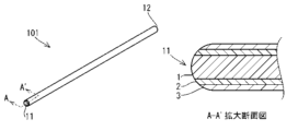
- the edge-emitting light guiding rod 101 in the modified example of Fig. 5 differs from the embodiment of Fig. 1 in that one end surface 11 is polished into a convex lens shape.
- LEDs generally emit light in all directions from the semiconductor.
- the directivity of the emitted light is slightly narrowed by the shape of the reflector and resin package, it still has a relatively wide directivity. Therefore, if the end face of the core layer 1 is flat, a large proportion of light below the critical angle will enter the core layer 1, and this light cannot be totally reflected, resulting in a decrease in the efficiency of light guiding.
- one end face 11 where light enters is polished into a convex lens shape, the incident light is refracted by the convex shape, narrowing the directivity.
- the angle of incidence to the cladding layer 2 becomes larger, and the proportion of light that exceeds the critical angle increases. As a result, more light can be guided by total reflection.
- the other end face 12 is left flat, but it can also be processed to have a matte finish. In this way, the light emitted from the other end face 12 can be diffused. Therefore, when incorporated into a product, there is no need to provide a separate window or lens component as an indicator, and the other end face 12 can be directly exposed to serve as the indicator window.
- the edge-emitting light guide rod of the present invention allows light entering from one end face to exit from the other end face, making it possible to position the LED and the light-emitting part in different positions even in products whose structure does not allow the incorporation of an LED and its peripheral components into the light-emitting part.
- the light-shielding layer integrally with the cladding layer, it is possible to prevent light leakage from the peripheral surface and to form the cladding layer and the light-shielding layer as thin as possible. Therefore, the diameter of the entire light guide rod can be made thin and flexible to bend. On the other hand, if the entire diameter is the same, the diameter of the core layer can be made relatively large, improving the light incidence efficiency and making the light-emitting part brighter.
- Example 1 had an overall diameter of 2.5 mm, and was configured using a core layer with a circular cross section and a diameter of 2 mm, around which a cladding layer with a thickness of 0.05 mm was provided, and a light-shielding layer with a thickness of 0.2 mm was provided around the cladding layer.
- the core layer is made of colorless and transparent polymethylmethacrylate (PMMA) elastomer resin
- the clad layer is made of colorless and transparent tetrafluoroethylene-ethylene copolymer (ETFE resin)
- the light-shielding layer is made of fluorine-based resin containing 0.9% by weight of carbon black throughout the product.
- Example 2 had the same configuration as Example 1, except that the overall diameter was 2 mm, of which the diameter of the core layer was 1.5 mm.
- Example 3 had the same configuration as Example 1, except that the overall diameter was 3.5 mm, of which the diameter of the core layer was 3 mm.
- Example 4 had the same configuration as Example 1, except that the overall diameter was 4 mm, of which the diameter of the core layer was 3.5 mm.
- Example 5 had the same configuration as Example 1, except that the overall diameter was 6.3 mm, of which the diameter of the core layer was 5.8 mm.
- Comparative Example 1 had an overall diameter of 2.04 mm, a core layer with a circular cross section and a diameter of 2 mm was used, and a clad layer with a thickness of 0.02 mm was provided around the core layer. No light-shielding layer was provided.
- the core layer was made of colorless and transparent PMMA resin
- the clad layer was made of colorless and transparent PVDF (polyvinylidene fluoride) resin.
- Comparative Example 2 Comparative Example 2 had an overall diameter of 3 mm, a circular cross-sectional core layer with a diameter of 2.98 mm, and a clad layer with a thickness of 0.01 mm provided around the core layer. No light-shielding layer was provided.
- the core layer was made of a colorless and transparent PMMA resin
- the clad layer was made of a colorless and transparent fluorine-based resin.
- Comparative Example 3 had an overall diameter of 2.2 mm, a core layer with a circular cross section and a diameter of 0.98 mm was used, a cladding layer with a thickness of 0.01 mm was provided around the core layer, and a light-shielding layer with a thickness of 0.6 mm was provided around the cladding layer.
- the core layer is made of colorless and transparent PMMA resin
- the cladding layer is made of colorless and transparent fluorine resin
- the light-shielding layer is made of black polyethylene resin.
- Bending test Three samples for the bending test were prepared for each of the above conditions, with lengths of 100 mm, 200 mm, and 300 mm. The bending test was performed by holding both ends of the sample with the hands, folding it back 180 degrees so that one end was aligned with the other end, and then pinching the folded part with the fingers to press it so that the folded part was as tight as possible. This was repeated in the opposite direction, alternating five times.
- the attenuation of the amount of transmitted light was also measured before and after the test using a spectroradiometer at a position 200 mm from the radiation end surface, using a red light source with a drive current of 300 mA and a light output of 3.634 lm.
- Example 1 “Test results” In Example 1, none of the samples of any length broke after the test, and the light-shielding layer did not crack or tear. The amount of light after the test was 92% on average compared to before the test. On the other hand, Comparative Examples 1 and 2 broke when bent in the opposite direction to the first bending.
- Three-point bending test For each of the three-point bending test samples, a length of 100 mm was prepared for each of the above conditions.
- the three-point bending test was performed according to JIS K 6911. In the test, the stroke and load of the indenter were measured, and the bending strain and bending stress were calculated to obtain a stress-strain diagram.
- the flexural modulus was calculated from the stress values at 0.05% strain and 0.25% strain in this stress-strain diagram (secant method). Note that the flexural modulus may also be calculated from the linear gradient of the load over a specified stroke (tangent method).
- Test results The test results for each sample are shown in the table below.
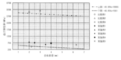
- the flexural modulus of elasticity in the above graph is plotted on a scatter diagram, it will look like Figure 6.
- the thicknesses of the cladding layer and the light-shielding layer are the same, but the diameters of the core layers are different in Examples 1 to 5. Since the core layer is made of an acrylic elastomer and is therefore soft, the bending modulus tends to decrease as the diameter of the core layer increases and the proportion of the core layer in the entire film increases.
- the light-shielding layer is relatively thick at 0.2 mm and contains carbon black, making it difficult to bend.
- the light-shielding properties are improved by incorporating a specified amount of carbon black into the fluororesin, while the material and diameter of the core layer are skillfully adjusted, resulting in a distribution between the upper and lower limits shown in Figure 6. This range is where the magnitude of a in the following formula is 550 or more and less than 3000.
- the value of a is 550 or more and less than 3000, the film is soft and easy to bend, and does not break when bent or the light-shielding layer is not damaged, causing light leakage.
- the value of a is preferably 600 or more and less than 2000, more preferably 650 or more and less than 1000, and even more preferably 700 or more and less than 900.
- the present invention has a light-shielding layer that contains carbon black, which has light-shielding and hardening properties, but is also characterized by being soft and difficult to break. Therefore, the light-emitting element and the light-emitting section can be placed in different positions without light leaking from the peripheral surface, and the light emitted from the light-emitting element can be efficiently guided.
Landscapes
- Physics & Mathematics (AREA)
- General Physics & Mathematics (AREA)
- Optics & Photonics (AREA)
- Light Guides In General And Applications Therefor (AREA)
Abstract
【課題】周面部から光が漏洩することなく、発光素子と発光部とを異なる位置に配置させることができるうえ、発光素子から発せられた光を効率良く導光することができる端面発光型導光棒を提供するとともに、前記端面発光型導光棒を、安価に製造することができる端面発光型導光棒の製造方法を提供すること。 【解決手段】光透過性を有する樹脂を主材とする棒状のコア層(1)と、前記コア層(1)の外周に配置され前記コア層(1)よりも屈折率が小さい樹脂を主材とするクラッド層(2)とを備え、前記コア層(1)の一方の端面(111)から入射した光を他方の端面(2)から出射する端面発光型導光棒(100)において、前記クラッド層(2)の外周には前記コア層(1)内を透過する光の波長を吸収する性質を有する樹脂を主材とする遮光層(3)を更に設け、前記遮光層(3)は前記クラッド層(2)と溶融一体に設ける構成とした。
Description
本発明は、一方の端面から入射した光を他方の端面から出射させることで、発光素子と発光部とを異なる位置に配置させることができる端面発光型導光棒及びその製造方法に関するものである。
産業機械や電気製品、自動車等の電気を用いる製品の多くには、動作状況の告知や装飾を目的として、所定の色の光を発するインジケータが備えられている。これらインジケータの発光素子には、消費電流の低さや寿命の長さから、LED(発光ダイオード)が用いられることが多い。
LEDを発光させるためには、LEDを駆動させるための電気回路を備えたプリント基板や配線、LEDを固定するホルダー等の周辺部品が必要になる。しかし、製品の大きさやインジケータを搭載する箇所のスペース等の制約によっては、発光部となる箇所にLEDを配置することが困難な場合もある。
LEDを発光させるためには、LEDを駆動させるための電気回路を備えたプリント基板や配線、LEDを固定するホルダー等の周辺部品が必要になる。しかし、製品の大きさやインジケータを搭載する箇所のスペース等の制約によっては、発光部となる箇所にLEDを配置することが困難な場合もある。
このような制約を有する製品においては、LEDから発せられた光を、導光部材(いわゆるライトガイド)によって、発光部まで導光する場合がある。一般的に、ライトガイドは、LEDから発せられた光を効率良く導光するために、反射や拡散の仕方を計算して設計される。つまり、製品に応じて個別に形状が最適化されるため、設計されたライトガイドは、ひとつの製品に対してのみ使用することができるものであって、複数の異なる製品に共通に用いることはできないという問題がある。
上述のような問題に対して、スペースに余裕がある箇所にLEDを配置し、そのLEDから発せられた光を、導光棒によって導光し、随意の箇所で発光させる方法がある。導光棒は、一般的には、光ファイバーに代表されるように、細く柔軟性を有しており、多少の湾曲が可能であるため、狭い箇所であっても這わせて配置することができる。
導光棒は、コア層の内部を光が透過して伝播することで、導光棒の一方の端面から入射した光を他方の端面へ導光して出射する。ここで、光は導光棒に対して平行に入射するだけでなく、所定の角度で入射する場合もあるが、そのような光のうち、臨界角を超える角度となった光は、コア層とコア層の外部の物質との屈折率の差によって、その境界面で全反射する。これにより、境界面で光が散乱して光の強度が減衰してしまうことなく、遠方まで光を減衰させずに導光させることができる。
導光棒の具体的な構成としては、コア層とその外部の空気層との屈折率の差を利用したものがある。しかし、コア層が外部に露出していると、使用中にコア層と空気層との境界面が傷付きやすくなり、傷による凹凸によって光が散乱して減衰する原因となる。そのため、コア層の外周に、コア層よりも屈折率の低いクラッド層と呼ばれる所定の厚さの層を被覆して、境界面を露出しないようにしたものが多く用いられている。
ところが、発光素子として用いられるLEDは、その構造上、発せられる光の指向性が広いため、コア層とクラッド層との屈折率の差に基づく臨界角を下回る角度の光も、コア層内に入射される。また、コア層とクラッド層との境界面に達した光の一部が散乱する場合もある。このような光のうち、前記臨界角を下回る角度の光は、コア層とクラッド層との境界面で全反射することなく、屈折してコア層からクラッド層内へ進入する。クラッド層内へ進入した光は、クラッド層と外部の空気層との境界面に達するが、この光のほとんどは、クラッド層から外部へ光が出射してしまう。このような漏洩した光は、製品にとって不必要な箇所を照らしてしまい、外観や機能上好ましくない。
そこで、従来においては、クラッド層から外部へ光が漏洩しないように構成された導光棒が開発されている。特許文献1には、クラッド層が「透明な内層クラッドと着色不透明な外層クラッドとにより構成」されたプラスチック光ファイバーの技術が開示されている。
特許文献1の技術では、まず、「内層クラッド用の樹脂をチューブ状に押出すと同時にその外周に上記内層クラッド用の樹脂と溶着し合う樹脂に着色剤を含有させた外層クラッド用の樹脂を同心円状に押出して上記内層クラッドと上記外層クラッドが溶着一体化したチューブ状のクラッドを成形」している。そして、「そのクラッドチューブにコア用の樹脂前駆体を加圧供給しながら加熱重合させる」方法で製造するとされている。
つまり、コア層とクラッド層とを同時に形成するのではなく、予めチューブ状に成形したクラッド層に対して、コア層となる樹脂を中空状の内部に加圧注入して成形する方法により製造している。
つまり、コア層とクラッド層とを同時に形成するのではなく、予めチューブ状に成形したクラッド層に対して、コア層となる樹脂を中空状の内部に加圧注入して成形する方法により製造している。
しかし、上述の特許文献1に記載の従来技術は、予めチューブ状のクラッド層を成形しなければならず、成形後にチューブ形状を維持し得るとともに、コア層となる樹脂の加圧注入に耐えうるだけの厚さや強度が必要となる。そのため、クラッド層及び遮光層をあまり薄くすることができない。
クラッド層及び遮光層が厚くなると、導光棒全体の直径が太くなってしまい、柔軟性が低下してしまい、製品内部へ取り付けしにくくなるという問題があった。
また、導光棒の最外径に設計上の上限が定められる場合には、クラッド層及び遮光層を厚くする一方で、コア層の直径は相対的に小さくしなければならない。そのため、LEDから発せられる光を入射するコア層の端面の面積が小さくなって、入射効率が低下し、ひいては発光部における発光強度を低下させてしまうという問題があった。
クラッド層及び遮光層が厚くなると、導光棒全体の直径が太くなってしまい、柔軟性が低下してしまい、製品内部へ取り付けしにくくなるという問題があった。
また、導光棒の最外径に設計上の上限が定められる場合には、クラッド層及び遮光層を厚くする一方で、コア層の直径は相対的に小さくしなければならない。そのため、LEDから発せられる光を入射するコア層の端面の面積が小さくなって、入射効率が低下し、ひいては発光部における発光強度を低下させてしまうという問題があった。
さらに、特許文献1に記載されている実施例のクラッド層では、その薄さのために、コア層の加圧注入時にクラッド層が膨らんでしまうことが考えられる。そのため導光棒全体の直径がクラッド層単体の直径よりも太くなってしまい、設計上許容される導光棒の最外径を満たすことができなくなる恐れがあるという問題もある。
そのうえ、クラッド層の成形と、コア層の成形とを別工程としなければならず、製造効率が悪くなって製品価格を上昇させてしまうという問題もあった。
そのうえ、クラッド層の成形と、コア層の成形とを別工程としなければならず、製造効率が悪くなって製品価格を上昇させてしまうという問題もあった。
本発明は、上記のような問題に鑑みてなされたものであり、その目的とするところは、周面部から光が漏洩することなく、発光素子と発光部とを異なる位置に配置させることができるうえ、発光素子から発せられた光を効率良く導光することができる端面発光型導光棒を提供することを目的とする。
また、前記端面発光型導光棒を、安価に製造することができる端面発光型導光棒の製造方法を提供することを目的とする。
また、前記端面発光型導光棒を、安価に製造することができる端面発光型導光棒の製造方法を提供することを目的とする。
本発明者が上記課題を解決するために採用した手段を以下に説明する。
本発明の端面発光型導光棒は、光透過性を有する樹脂を主材とする棒状のコア層と、前記コア層の外周に配置され前記コア層よりも屈折率が小さい樹脂を主材とするクラッド層とを備えることを基本的な構成としており、前記コア層の一方の端面から入射した光を他方の端面から出射する機能を有する端面発光型導光棒である。
本発明の端面発光型導光棒は、光透過性を有する樹脂を主材とする棒状のコア層と、前記コア層の外周に配置され前記コア層よりも屈折率が小さい樹脂を主材とするクラッド層とを備えることを基本的な構成としており、前記コア層の一方の端面から入射した光を他方の端面から出射する機能を有する端面発光型導光棒である。
ここで、「光透過性を有する」とは、導光棒を用いる製品にとって必要十分な光の強度を導光できる程度の透過性を有していればよく、可視光だけでなく、装飾性や機能性によっては紫外線や赤外線等、可視光線以外の光に対しての透過性を有している場合も含まれる。
また、「主材とする」とは、全体におけるその樹脂の比率が最も高いということを意味し、他の素材が含有している場合も含まれる。
また、「主材とする」とは、全体におけるその樹脂の比率が最も高いということを意味し、他の素材が含有している場合も含まれる。
本発明の端面発光型導光棒は、上記基本構成に対して、前記クラッド層の外周に前記コア層内を透過する光の波長を吸収する性質を有する樹脂を主材とする遮光層を更に設け、前記遮光層を前記クラッド層とを溶融一体に設けていることを特徴としている。
クラッド層の外周に遮光層を設けることで、臨界角以下の角度で入射した光や、コア層とクラッド層の境界で散乱した一部の光を吸収するため、クラッド層から外部への光の漏洩を防止することができる。
クラッド層の外周に遮光層を設けることで、臨界角以下の角度で入射した光や、コア層とクラッド層の境界で散乱した一部の光を吸収するため、クラッド層から外部への光の漏洩を防止することができる。
また、遮光層とクラッド層とを溶融一体に形成することで、それらが異なる線膨張係数であったとしても、環境温度の変化等に起因して、各層の膨縮量の相違により分離してしまうという不具合が生じにくくなる。
それに加えて、溶融一体に形成することで、単独で形成する場合と比較して強度を確保しやすくなり、より薄く形成することができる。そのため、導光棒全体の直径を小さくすることができ、柔軟に湾曲させてやすくなって製品へ組み込みやすくなる。また、同じ強度とするならば、各層を薄くすることができ、相対的にコア層の直径を大きくすることができるため、大きな角度で発せられた光もコア層内に進入させることができ、入射効率を向上させることができる。
それに加えて、溶融一体に形成することで、単独で形成する場合と比較して強度を確保しやすくなり、より薄く形成することができる。そのため、導光棒全体の直径を小さくすることができ、柔軟に湾曲させてやすくなって製品へ組み込みやすくなる。また、同じ強度とするならば、各層を薄くすることができ、相対的にコア層の直径を大きくすることができるため、大きな角度で発せられた光もコア層内に進入させることができ、入射効率を向上させることができる。
ここで、「コア層内を透過する光の波長を吸収する性質」とは、可視光線の波長域全体を吸収する黒色であることに限られず、コア層内を透過する光が単一あるいは特定の範囲の波長である場合には、それらの波長の光のみを吸収し、その他の波長の光は反射や透過をするような性質である場合も含まれる。
前述の課題を解決するために本発明が採用した手段としては、上記手段に加え、前記クラッド層の厚みを0.15mm以下とし、前記遮光層の厚みを0.25mm以下とすることも可能である。
導光棒の最外径は、取り付ける製品の空間の大きさや、フェルールを接続する場合にはフェルールの規格によって、特定の直径とすることが求められる場合もある。同じ最外径であれば、クラッド層の厚みを0.15mm以下、遮光層の厚みを0.25mm以下とごく薄く形成することで、相対的にコア層の直径を大きくすることができるため、入射効率を向上させることができる。また、発光素子の大きさによってコア層の直径が予め定められる場合には、導光棒の最外径をより小さくすることができるため、柔軟に湾曲させることができ、製品へ取り付けしやすくなる。
導光棒の最外径は、取り付ける製品の空間の大きさや、フェルールを接続する場合にはフェルールの規格によって、特定の直径とすることが求められる場合もある。同じ最外径であれば、クラッド層の厚みを0.15mm以下、遮光層の厚みを0.25mm以下とごく薄く形成することで、相対的にコア層の直径を大きくすることができるため、入射効率を向上させることができる。また、発光素子の大きさによってコア層の直径が予め定められる場合には、導光棒の最外径をより小さくすることができるため、柔軟に湾曲させることができ、製品へ取り付けしやすくなる。
また、前記遮光層にはカーボンブラックを0.01重量%以上含有させた樹脂が用いられるようにすることも可能である。
カーボンブラックは微細な炭素微粒子であり、特に可視光における波長域の全体を強く吸収する性質を有する。このカーボンブラックの含有量が0.01重量%未満であると、遮光層内を透過する光の割合が増加し、十分な遮光性を得ることが困難になる。しかし、カーボンブラックを、遮光層を構成する樹脂の0.01重量%以上含有させることで、どのような色の発光素子を用いたとしても、十分な遮光性能を得ることができる。
一方、カーボンブラックを、遮光層を構成する樹脂の5.0重量%を超えて含有させると、成形時に表面割れが発生する可能性がある。そのため、カーボンブラックの含有量は、遮光層を構成する樹脂の5.0重量%以下とすることが望ましい。
上記手段を採用する場合には、さらに、前記コア層にアクリル系エラストマーを主材とする樹脂を用い、前記クラッド層にはフッ素系樹脂を主材とする樹脂を用いて構成することもできる。この場合、前記遮光層には、前記クラッド層とともに共押出成形可能なガラス転移温度を有する樹脂を用いる。
コア層にアクリル系エラストマーを主材とする樹脂を用いることで、導光棒を柔軟に湾曲させることができ、製品の形状に合わせて這わせることができるようになる。また、クラッド層にフッ素系樹脂を用いるとともに、遮光層にはクラッド層とともに共押出成形可能なガラス転移温度を有する樹脂を用いることで、同一条件の成形工程で溶融一体化させることができるようになる。
コア層にアクリル系エラストマーを主材とする樹脂を用いることで、導光棒を柔軟に湾曲させることができ、製品の形状に合わせて這わせることができるようになる。また、クラッド層にフッ素系樹脂を用いるとともに、遮光層にはクラッド層とともに共押出成形可能なガラス転移温度を有する樹脂を用いることで、同一条件の成形工程で溶融一体化させることができるようになる。
さらに、前記遮光層の厚みを0.1mm以上とし、JIS K 6911に基づく3点曲げによる曲げ試験において、導光棒全体の直径と曲げ弾性率との関係を表す下記式におけるaの大きさを550以上3000未満とすることも可能である。

y:曲げ弾性率[MPa] x:導光棒全体の直径[mm]
y:曲げ弾性率[MPa] x:導光棒全体の直径[mm]
遮光層の厚さを0.1mm以上とすることで周面からの光の漏洩を確実に防止することができる一方で、遮光層に含まれるカーボンブラックにより遮光層が硬くなる。
しかし、3点曲げを行ったときの曲げ弾性率が、上記式におけるaの大きさを550以上3000未満の範囲とすることで、曲げやすく柔らかい導光棒でありながら、周面からの光の漏れを確実に防止することができる。
しかし、3点曲げを行ったときの曲げ弾性率が、上記式におけるaの大きさを550以上3000未満の範囲とすることで、曲げやすく柔らかい導光棒でありながら、周面からの光の漏れを確実に防止することができる。
ところで、光透過性を有する樹脂を主材とする棒状のコア層と、前記コア層の外周に配置され前記コア層よりも屈折率が小さい樹脂を主材とするクラッド層とを備えた導光棒の製造方法においては、以下の構成の製造方法とすることができる。
本発明の製造方法には、前記クラッド層の外周に前記コア層内を透過する光の波長を吸収する性質を有する樹脂を主材とする遮光層が更に設けられるように構成された金型を用いる。そして、前記コア層と前記クラッド層と前記遮光層とを共押出し成形により一体に成形する。
本発明の製造方法には、前記クラッド層の外周に前記コア層内を透過する光の波長を吸収する性質を有する樹脂を主材とする遮光層が更に設けられるように構成された金型を用いる。そして、前記コア層と前記クラッド層と前記遮光層とを共押出し成形により一体に成形する。
上記のように、コア層とクラッド層に加え、コア層内を透過する光の波長を吸収する性質を有する樹脂を主材とする遮光層を一つの金型で同時に共押出し成形することにより、同一条件の成形工程で溶融一体化させることができる。
これにより、前述のようにクラッド層及び遮光層を薄く形成するとともに、相対的にコア層の直径を大きくすることができるため、入射効率を向上させることができる。また、同一条件の成形工程で溶融一体化させるため、製造工程を単純化することができる。
これにより、前述のようにクラッド層及び遮光層を薄く形成するとともに、相対的にコア層の直径を大きくすることができるため、入射効率を向上させることができる。また、同一条件の成形工程で溶融一体化させるため、製造工程を単純化することができる。
前述のように、本発明における端面発光型導光棒では、クラッド層の外周にコア層内を透過する光の波長を吸収する性質を有する樹脂を主材とする遮光層を設けている。また、遮光層とクラッド層とを溶融一体に設けている。
これらの構成により、クラッド層の外部に漏洩する光が遮光層により吸収されるため、クラッド層から外部への光の漏洩を防止することができる。また、クラッド層と遮光層とを溶融一体に形成することで、各層を薄く形成しても形状を維持することができるため、導光棒全体の直径を小さくすることができ、より柔軟になって湾曲させやすくすることができる。また、相対的にコア層の直径を大きくすることができるため、入射効率を向上させることができる。
上記作用により、本発明では、周面部から光が漏洩することなく、発光素子と発光部とを異なる位置に配置させることができるうえ、発光素子から発せられた光を効率良く導光することができる端面発光型導光棒とすることができるという効果がある。
また、本発明における端面発光型導光棒の製造方法では、コア層とクラッド層に加え、コア層内を透過する光の波長を吸収する性質を有する樹脂を主材とする遮光層を一つの金型で同時に共押出し成形する構成としている。この構成により、同一条件の成形工程で溶融一体化させることができる。
上記作用により、本発明では、端面発光型導光棒を安価に製造することができるという効果がある。
上記作用により、本発明では、端面発光型導光棒を安価に製造することができるという効果がある。
本発明を実施するための形態について、図1から図4に基づいて以下に説明する。
なお、図は説明のために模式的に記載されており、寸法や形状は実際とは異なる。
なお、図は説明のために模式的に記載されており、寸法や形状は実際とは異なる。
本発明の実施の形態の一例である端面発光型導光棒100は、図1に示すように、光透過性を有する樹脂を主材とする棒状のコア層1と、コア層1の外周に配置されコア層1よりも屈折率が小さい樹脂を主材とするクラッド層2とを備えている。
また、クラッド層2の外周側には、コア層内を透過する光の波長を吸収する性質を有する樹脂を主材とする遮光層3が更に設けられている。
これらコア層1とクラッド層2と遮光層3とは、後述する製造方法により、溶融一体化されて構成されている。
また、クラッド層2の外周側には、コア層内を透過する光の波長を吸収する性質を有する樹脂を主材とする遮光層3が更に設けられている。
これらコア層1とクラッド層2と遮光層3とは、後述する製造方法により、溶融一体化されて構成されている。
図1の実施形態では、コア層1の主材に、柔軟なアクリル系エラストマーであるメタクリル酸メチル-アクリル酸n-ブチル-アクリル酸ベンジルのブロック共重合体を使用しているが、熱可塑性エラストマーであるメタクリル酸メチルとアクリル酸ブチルのブロック共重合体(MMA-BAブロック共重合体)、またはアクリル酸メチルとアクリル酸ブチルのブロック共重合体、またはメタクリル酸メチル(アクリル酸メチル)とアクリル酸エステルとアクリル酸芳香族エステルからなるアクリル系ブロック共重合体、ポリメチルメタクリレート(PMMA:屈折率1.49)、熱可塑性ポリウレタン(TPU:屈折率1.49)、環状オレフィン(屈折率1.50)、非晶性ポリアミド(PA:屈折率1.51)、ポリカーボネート(PC:屈折率1.56)の1種または複数種を好適に使用できる。
また、柔軟性のあるアクリル系エラストマーとガラス転移温度(Tg)が常温(25℃)以上の硬質アクリル系樹脂との混合材料を用いてもよいが、アクリル系エラストマーの含有比率の方が硬質アクリル系樹脂よりも多い方が柔軟は高くなる。その他、押出成形可能な樹脂であれば、他の熱可塑性樹脂や熱硬化性樹脂を用いることも可能である。
また、柔軟性のあるアクリル系エラストマーとガラス転移温度(Tg)が常温(25℃)以上の硬質アクリル系樹脂との混合材料を用いてもよいが、アクリル系エラストマーの含有比率の方が硬質アクリル系樹脂よりも多い方が柔軟は高くなる。その他、押出成形可能な樹脂であれば、他の熱可塑性樹脂や熱硬化性樹脂を用いることも可能である。
上記コア層1の形状に関しては、図1の実施形態では、断面形状が円形状のものを使用しており、直径は任意であるが、6.3mm、3.5mm、2.5mm等、砲弾形のLEDやチップLEDの発光面の大きさに合わせて選択するのが好ましい。コア層1の形状については、かまぼこ型の半楕円形状や製品の内部構造に嵌合しやすい形状、その他、楕円形状や半円形状、多角形状等を採用することもできる。
また、コア層1はクラッド層2及び遮光層3と同心となるように構成されているが、コア層1を、クラッド層2及び遮光層3の中心に対して偏心させることも可能である。この場合、特定の方向に対しての遮光性を高めたり、一方向にのみ湾曲させやすくしたりすることができる。
また、コア層1はクラッド層2及び遮光層3と同心となるように構成されているが、コア層1を、クラッド層2及び遮光層3の中心に対して偏心させることも可能である。この場合、特定の方向に対しての遮光性を高めたり、一方向にのみ湾曲させやすくしたりすることができる。
一方、図1の実施形態では、クラッド層2の主材に、フッ素系樹脂であるエチレンとテトラフルオロエチレンの共重合体(ETFE:屈折率1.40)を使用しているが、ヘキサフルオロプロピレンとテトラフルオロエチレンとエチレンの共重合体(EFEP:屈折率1.38)、ポリフッ化ビニリデン(PVDF:屈折率1.42)、四フッ化エチレンとパーフルオロアルコキシエチレンの共重合体(PFA:屈折率1.34)、テトラフルオロエチレンとヘキサフルオロプロピレンの共重合体(FEP:屈折率1.34)、ポリメチルペンテン(TPX:屈折率1.46)の1種または複数種を好適に使用できる。クラッド層2の主材に摩擦係数の小さいフッ素系樹脂を使用し、後述する遮光層3にも同様の樹脂を用いることで、製品の内部構造に差し込んだり挟み込んだりして這わせやすくなる。
また、押出成形可能な樹脂でコア層よりも屈折率の低い樹脂であれば、ポリメチルメタクリレート(PMMA:屈折率1.49)、熱可塑性ポリウレタン(TPU:屈折率1.49)、環状オレフィン(屈折率1.50)、非晶性ポリアミド(PA:屈折率1.51)等の熱可塑性樹脂や他の熱硬化性樹脂を用いることも可能である。
また、押出成形可能な樹脂でコア層よりも屈折率の低い樹脂であれば、ポリメチルメタクリレート(PMMA:屈折率1.49)、熱可塑性ポリウレタン(TPU:屈折率1.49)、環状オレフィン(屈折率1.50)、非晶性ポリアミド(PA:屈折率1.51)等の熱可塑性樹脂や他の熱硬化性樹脂を用いることも可能である。
上記クラッド層2の形状に関しては、図1の実施形態では、コア層1の外周に所定の厚みで形成されていればよく、導光棒全体の直径を小さくして湾曲させやすくしたり、コア層1の直径を相対的に大きくして入射効率を高めたりするために、厚さは0.15mm以下であるのが好ましく、より好ましくは、0.1mm以下、さらに好ましくは0.05mm以下である。
また、クラッド層2の層構造は、一層構造でも、複数のクラッド層2・2…からなる多層構造であってもよい。
また、クラッド層2の層構造は、一層構造でも、複数のクラッド層2・2…からなる多層構造であってもよい。
上記コア層1とクラッド層2の屈折率差は0.01以上であると全反射が起こりやすく光を効率よく導光することができるが、0.07以上であるとより好ましい。
また、遮光層3には、カーボンブラックを0.01重量%含有させたものを使用している。カーボンブラックは粒径数nmから数百nmの微細な炭素粉末であり、所定の光の波長域を強く吸収する性質を有するものであれば、単一の炭素原子からなるものの他、表面に様々な官能基が結合した組成をもつものを使用することもできる。
カーボンブラックの含有量は、遮光性能と割れ等の成形不良防止の観点から0.01重量%以上5.0重量%以下とし、このましくは0.2重量%以上5.0重量%以下であり、より好ましくは0.8重量%以上5.0重量%以下である。
また、遮光層3に含有させる黒色の着色材としては、例えば、酸化銅系や酸化鉄系の複合酸化物、チタン系黒顔料等を用いることができ、コア層1内を導光する光が、例えば特定の狭い波長域からなる単色の光であるならば、その波長域の光のみを吸収するようにした有色の顔料を用いるようにしてもよい。
カーボンブラックの含有量は、遮光性能と割れ等の成形不良防止の観点から0.01重量%以上5.0重量%以下とし、このましくは0.2重量%以上5.0重量%以下であり、より好ましくは0.8重量%以上5.0重量%以下である。
また、遮光層3に含有させる黒色の着色材としては、例えば、酸化銅系や酸化鉄系の複合酸化物、チタン系黒顔料等を用いることができ、コア層1内を導光する光が、例えば特定の狭い波長域からなる単色の光であるならば、その波長域の光のみを吸収するようにした有色の顔料を用いるようにしてもよい。
遮光層3の主材については、共押出し成形によりクラッド層2と同時に溶融一体に成形することができることが必要であり、上述のようにクラッド層2と同様の、フッ素系樹脂であるエチレンとテトラフルオロエチレンの共重合体(ETFE)を用いることができるが、その他にも、ヘキサフルオロプロピレンとテトラフルオロエチレンとエチレンの共重合体(EFEP)、ポリフッ化ビニリデン(PVDF)、四フッ化エチレンとパーフルオロアルコキシエチレンの共重合体(PFA)、テトラフルオロエチレンとヘキサフルオロプロピレンの共重合体(FEP)等の1種または複数種を好適に使用できる。
また、押出成形可能な樹脂であれば、軟質ポリ塩化ビニール(PVC)やオレフィン系熱可塑性エラストマー(TPO)、スチレン系熱可塑性エラストマー(TPS)、熱可塑性ポリウレタン(TPU)、熱可塑性エラストマー(TPE)、ポリアミド系熱可塑性エラストマ(TPA)等の熱可塑性樹脂や他の熱硬化性樹脂を用いることも可能であり、同程度のガラス転移温度を有することで共押出し成形によりクラッド層2とともに押出し成形することができるものであれば、他の樹脂を用いても良い。
また、押出成形可能な樹脂であれば、軟質ポリ塩化ビニール(PVC)やオレフィン系熱可塑性エラストマー(TPO)、スチレン系熱可塑性エラストマー(TPS)、熱可塑性ポリウレタン(TPU)、熱可塑性エラストマー(TPE)、ポリアミド系熱可塑性エラストマ(TPA)等の熱可塑性樹脂や他の熱硬化性樹脂を用いることも可能であり、同程度のガラス転移温度を有することで共押出し成形によりクラッド層2とともに押出し成形することができるものであれば、他の樹脂を用いても良い。
上記遮光層3の形状に関しては、図1の実施形態では、クラッド層2の外周に所定の厚みで形成されていればよく、上述のクラッド層2の厚さの選択理由と、十分な遮光特性を得ることのバランスとを考慮して、厚さは0.25mm以下であるのが好ましく、より好ましくは、0.2mm以下である。
また、遮光層3の層構造についても、一層構造でも、複数の遮光層3・3…からなる多層構造であってもよい。
また、遮光層3の層構造についても、一層構造でも、複数の遮光層3・3…からなる多層構造であってもよい。
なお、本発明の端面発光型導光棒100は、周面からの発光を防止し、端面からのみ発光させることが目的であるため、図1の実施形態においては、コア層1及びクラッド層2には酸化チタン等の光散乱剤を含有させていない。しかし、周面からの発光は遮光層3で防止されるため、端面から均一な拡散光を出射させることを目的として、光散乱剤をコア層1に含有させるようにしてもよい。
また、本発明の端面発光型導光棒100は、屋外で太陽光に暴露した状態で使用しない場合には、図1の実施形態においては、コア層1にはブルーイング剤を含有させる必要がない。しかし、紫外線のLEDと可視光線のLEDとを併用して用いる場合等には、紫外線によりコア層1を黄変させてしまい、可視光線の発光時に色味が変わってしまうことがあるため、コア層1に青色顔料等のブルーイング剤を含有させるようにしてもよい。
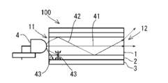
次に、本発明の端面発光型導光棒100の内部を進行する光の動きについて、図2に基づいて説明する。図2において、コア層1の一方の端面11に、発光素子であるLED4から発せられる光が入射する。入射した光のうち、コア層1の長手方向に平行な方向に入射した平行光41はコア層1内を直進する。また、コア層1の長手方向に対して所定の角度で入射した光のうち、臨界角を超える光42は、コア層1とクラッド層2の境界面で全反射を繰り返してコア層1内を進行する。
しかし、臨界角以下の光43は、コア層1とクラッド層2の境界面で全反射せず、屈折してクラッド層2の内部へ進入する。また、臨界角を超える角度で入射されたとしても、コア層1とクラッド層2との境界面では、少なからず散乱が生じる。この散乱光の一部はクラッド層2の内部に向かって進行する。このような理由によりクラッド層2の内部へ進入した光は、クラッド層2と遮光層3との境界へ達する。このとき、遮光層3の樹脂に含有するカーボンブラックや有色顔料の粒子が、クラッド層2と遮光層3との境界へ達した光を吸収する。
このように、クラッド層2から遮光層3に達した光が吸収されることで、外部へ光が漏洩することを防止することができる他、コア層1へ光が戻ることもないため、端面から出射される光の指向性が意図しない特性となることも防止することができる。
このように、クラッド層2から遮光層3に達した光が吸収されることで、外部へ光が漏洩することを防止することができる他、コア層1へ光が戻ることもないため、端面から出射される光の指向性が意図しない特性となることも防止することができる。
上述のような特徴を有する端面発光型導光棒100は、図3に示すように、製品200の内部に組み込まれて、任意の箇所を発光させるインジケータの一部を構成する。
図3の実施形態では、製品200は、例えば電気製品の筐体の一部である。製品200の内部の大部分は空間が広く構成されているが、インジケータを配置する右側端部は極端に空間が狭くなっている。このような狭い空間にLED4を配置しようとすると、仮にLED4が寸法の小さなチップLEDであったとしても、LED4を駆動するためのプリント基板210を配置することができない。
図3の実施形態では、製品200は、例えば電気製品の筐体の一部である。製品200の内部の大部分は空間が広く構成されているが、インジケータを配置する右側端部は極端に空間が狭くなっている。このような狭い空間にLED4を配置しようとすると、仮にLED4が寸法の小さなチップLEDであったとしても、LED4を駆動するためのプリント基板210を配置することができない。
そこで、製品200の空間の広い部分に、LED4を搭載したプリント基板210を配置し、LED4の発光面に一方の端面11が近接するように端面発光型導光棒100を配置する。そして、端面発光型導光棒100を製品200の内部に這わせて、他方の端面12を発光部220に対向させて配置する。
このような構成とすることで、LED4やその駆動のためのプリント基板210を配置することができないような狭い内部構造を有する部分にも、発光部220を設けることができ、随意の場所をインジケータとすることができる。また、端面発光型導光棒100は柔軟性があり、その長さも容易に変更できることから、製品ごとに導光部材となるライドガイドを個別に設計製造する必要がない。そのため、端面発光型導光棒100を複数の多様な製品に共通の部品として使用することができ、製造原価や部品管理工数を低減させることができる。
次に、本発明の端面発光型導光棒100の製造方法について、図4に基づいて説明する。本発明の端面発光型導光棒100は、共押出し成形により、コア層1、クラッド層2及び遮光層3を同時に溶融一体化して成形する。
本発明の製造方法は、図4に示すような製造装置5を用い、コア層1、クラッド層2及び遮光層3が同心円状となるように構成された金型51を用いる。金型51のコア層1となる部分、クラッド層2となる部分、遮光層3となる部分には、それぞれに対応する樹脂を投入するシリンダー52・52’・52’’が接続されており、それぞれのホッパーに樹脂を投入し、溶融した樹脂をスクリューによって金型51内に送り出す。
本発明の製造方法は、図4に示すような製造装置5を用い、コア層1、クラッド層2及び遮光層3が同心円状となるように構成された金型51を用いる。金型51のコア層1となる部分、クラッド層2となる部分、遮光層3となる部分には、それぞれに対応する樹脂を投入するシリンダー52・52’・52’’が接続されており、それぞれのホッパーに樹脂を投入し、溶融した樹脂をスクリューによって金型51内に送り出す。
金型51内では、溶融した樹脂により、コア層1、クラッド層2及び遮光層3が金型形状に従って成形され、それらの層が溶融一体化されて押し出される。このように押出し成形された後、冷却水槽53によって冷却固化され、引き取り機54によって引き取られた後、カッター55で所定の長さに切断される。
上記のように、共押し出し成形によって、コア層1、クラッド層2及び遮光層3を同時に溶融一体化することで、一つの製造工程で製造が可能となり、端面発光型導光棒100を安価に製造することができる。
上記のように、共押し出し成形によって、コア層1、クラッド層2及び遮光層3を同時に溶融一体化することで、一つの製造工程で製造が可能となり、端面発光型導光棒100を安価に製造することができる。
『変形例』
ところで、本発明の端面発光型導光棒は、上記の実施形態に限られず、他の形態によっても実施することができる。図5の変形例における端面発光型導光棒101では、図1の形態に対して、一方の端面11を凸レンズ状に研磨加工した点が異なる。
導光棒の伝送効率を向上させるためには、できるだけ多くの光を、臨界角を超える角度で入射させる必要がある。しかし、LEDは一般的に半導体からは全方向に光が出射する。出射した光は反射板や樹脂パッケージの形状によって、僅かに指向性が狭められているものの、比較的広い指向性を有している。そのため、コア層1の端面が平らであると、臨界角以下の光の割合が多いままコア層1内に進入することになり、その光については全反射させることができないため、導光の効率が低下する。
そこで、光が入射する一方の端面11を研磨によって凸レンズ状に形成すると、凸形状によって入射した光が屈折し、指向性が狭くなる。換言すると、クラッド層2に対する入射角が大きくなるため、臨界角を超える光の割合が多くなる。そのため、より多くの光を全反射によって導光させることができる。
なお、本変形例では、他方の端面12は平らなままとしているが、梨地状に加工することも可能である。このようにすることで、他方の端面12から出射する光を拡散させることができる。そのため、製品に組み込んだ場合に、インジケータとしての別体の窓部品やレンズ部品を設ける必要がなく、他方の端面12を直接露出させてインジケータの窓とするこができる。
以上のように、本発明の端面発光型導光棒は、一方の端面から入射した光を他方の端面から出射させることで、発光部にLEDやその周辺部品を組み込むことができないような構造の製品であっても、LEDと発光部とを異なる位置に配置させることができるようになる。
また、遮光層をクラッド層と溶融一体に設けたことで、周面からの光の漏洩を防止することができるとともに、クラッド層と遮光層とをできるだけ薄く形成することができる。そのため、導光棒全体の直径を細く柔軟に湾曲可能に構成することができる。その一方で、全体が同じ直径であれば、コア層の直径を相対的に大きくできるため、光の入射効率が向上し、発光部をより明るくすることができる。
また、遮光層をクラッド層と溶融一体に設けたことで、周面からの光の漏洩を防止することができるとともに、クラッド層と遮光層とをできるだけ薄く形成することができる。そのため、導光棒全体の直径を細く柔軟に湾曲可能に構成することができる。その一方で、全体が同じ直径であれば、コア層の直径を相対的に大きくできるため、光の入射効率が向上し、発光部をより明るくすることができる。
次に、本発明の導光棒の具体的な実施例と、従来技術の導光棒である比較例とについて、屈曲試験に対する耐性及び3点曲げ試験を行い、結果の比較を行った。
「実施例1」
実施例1は、全体の直径が2.5mmであり、断面円形の直径2mmのコア層を用い、その周囲に厚さ0.05mmのクラッド層を設け、クラッド層の周囲に厚さ0.2mmの遮光層を設けた構成とした。
コア層には無色透明のポリメタクリル酸メチル(PMMA)系エラストマー樹脂を用い、クラッド層には無色透明のテトラフルオロエチレン-エチレン共重合体(ETFE樹脂)を用いた。遮光層にはカーボンブラックを製品全体で0.9重量%となるように含有させたフッ素系樹脂を用いた。
実施例1は、全体の直径が2.5mmであり、断面円形の直径2mmのコア層を用い、その周囲に厚さ0.05mmのクラッド層を設け、クラッド層の周囲に厚さ0.2mmの遮光層を設けた構成とした。
コア層には無色透明のポリメタクリル酸メチル(PMMA)系エラストマー樹脂を用い、クラッド層には無色透明のテトラフルオロエチレン-エチレン共重合体(ETFE樹脂)を用いた。遮光層にはカーボンブラックを製品全体で0.9重量%となるように含有させたフッ素系樹脂を用いた。
「実施例2」
実施例2は、全体の直径が2mmであり、そのうちコア層の直径が1.5mmである以外は実施例1と同様の構成とした。
実施例2は、全体の直径が2mmであり、そのうちコア層の直径が1.5mmである以外は実施例1と同様の構成とした。
「実施例3」
実施例3は、全体の直径が3.5mmであり、そのうちコア層の直径が3mmである以外は実施例1と同様の構成とした。
実施例3は、全体の直径が3.5mmであり、そのうちコア層の直径が3mmである以外は実施例1と同様の構成とした。
「実施例4」
実施例4は、全体の直径が4mmであり、そのうちコア層の直径が3.5mmである以外は実施例1と同様の構成とした。
実施例4は、全体の直径が4mmであり、そのうちコア層の直径が3.5mmである以外は実施例1と同様の構成とした。
「実施例5」
実施例5は、全体の直径が6.3mmであり、そのうちコア層の直径が5.8mmである以外は実施例1と同様の構成とした。
実施例5は、全体の直径が6.3mmであり、そのうちコア層の直径が5.8mmである以外は実施例1と同様の構成とした。
「比較例1」
比較例1は、全体の直径が2.04mmであり、断面円形の直径2mmのコア層を用い、その周囲に厚さ0.02mmのクラッド層を設けた構成とした。なお、遮光層は設けていない。
コア層には無色透明のPMMA樹脂を用い、クラッド層には無色透明のPVDF(ポリフッ化ビニリデン) 樹脂を用いた。
比較例1は、全体の直径が2.04mmであり、断面円形の直径2mmのコア層を用い、その周囲に厚さ0.02mmのクラッド層を設けた構成とした。なお、遮光層は設けていない。
コア層には無色透明のPMMA樹脂を用い、クラッド層には無色透明のPVDF(ポリフッ化ビニリデン) 樹脂を用いた。
「比較例2」
比較例2は、全体の直径が3mmであり、断面円形の直径2.98mmのコア層を用い、その周囲に厚さ0.01mmのクラッド層を設けた構成とした。なお、遮光層は設けていない。
コア層には無色透明のPMMA樹脂を用い、クラッド層には無色透明のフッ素系樹脂を用いた。
比較例2は、全体の直径が3mmであり、断面円形の直径2.98mmのコア層を用い、その周囲に厚さ0.01mmのクラッド層を設けた構成とした。なお、遮光層は設けていない。
コア層には無色透明のPMMA樹脂を用い、クラッド層には無色透明のフッ素系樹脂を用いた。
「比較例3」
比較例3は、全体の直径が2.2mmであり、断面円形の直径0.98mmのコア層を用い、その周囲に厚さ0.01mmのクラッド層を設け、クラッド層の周囲に厚さ0.6mmの遮光層を設けた構成とした。
コア層には無色透明のPMMA樹脂を用い、クラッド層には無色透明のフッ素系樹脂を用いた。遮光層には、黒色のポリエチレン樹脂を用いた。
比較例3は、全体の直径が2.2mmであり、断面円形の直径0.98mmのコア層を用い、その周囲に厚さ0.01mmのクラッド層を設け、クラッド層の周囲に厚さ0.6mmの遮光層を設けた構成とした。
コア層には無色透明のPMMA樹脂を用い、クラッド層には無色透明のフッ素系樹脂を用いた。遮光層には、黒色のポリエチレン樹脂を用いた。
『屈曲試験』
屈曲試験の各サンプルは、上記の条件ごとに、長さ100mm、200mm、300mmの3種類ずつ準備した。
屈曲試験の試験方法は、サンプルの両端を手で把持し、一端部が他端部側に揃うように180度折り返した後、屈曲部を指でつまんで折り返し部分がなるべく密着するように押さえる。これを反対方向にも行い、交互に5回繰り返した。
試験サンプルは、実施例1と、比較例1及び比較例2とし、各N=3で実施した。
また、試験の前後における透過光量の減衰量を測定した。測定については、分光放射輝度計を用い、駆動電流300mA、光量3.634lmの赤色光源にて、放射端面から200mmの位置で測定した。
屈曲試験の各サンプルは、上記の条件ごとに、長さ100mm、200mm、300mmの3種類ずつ準備した。
屈曲試験の試験方法は、サンプルの両端を手で把持し、一端部が他端部側に揃うように180度折り返した後、屈曲部を指でつまんで折り返し部分がなるべく密着するように押さえる。これを反対方向にも行い、交互に5回繰り返した。
試験サンプルは、実施例1と、比較例1及び比較例2とし、各N=3で実施した。
また、試験の前後における透過光量の減衰量を測定した。測定については、分光放射輝度計を用い、駆動電流300mA、光量3.634lmの赤色光源にて、放射端面から200mmの位置で測定した。
「試験結果」
実施例1は、何れの長さのサンプルについても、試験後に折れることはなく、遮光層のひび割れや裂けもなかった。試験後における光量は、試験前と比較して、平均で92%であった。
一方、比較例1及び比較例2は、1回目の屈曲時に反対方向に折り曲げたときに折れた。
実施例1は、何れの長さのサンプルについても、試験後に折れることはなく、遮光層のひび割れや裂けもなかった。試験後における光量は、試験前と比較して、平均で92%であった。
一方、比較例1及び比較例2は、1回目の屈曲時に反対方向に折り曲げたときに折れた。
『3点曲げ試験』
3点曲げ試験の各サンプルは、上記の条件ごとに、長さ100mmのものを準備した。
3点曲げ試験の試験方法は、JIS K 6911に準ずる方法で行った。
試験では圧子のストロークと荷重を測定し、計算により曲げひずみと曲げ応力を求め、応力‐ひずみ線図を得た。
この応力‐ひずみ線図の0.05%ひずみ時と0.25%ひずみ時の各応力値から曲げ弾性率を算出した(割線法)。なお、曲げ弾性率は、所定のストローク間の荷重の直線勾配から計算により求める方法(接線法)を採用しても良い。
3点曲げ試験の各サンプルは、上記の条件ごとに、長さ100mmのものを準備した。
3点曲げ試験の試験方法は、JIS K 6911に準ずる方法で行った。
試験では圧子のストロークと荷重を測定し、計算により曲げひずみと曲げ応力を求め、応力‐ひずみ線図を得た。
この応力‐ひずみ線図の0.05%ひずみ時と0.25%ひずみ時の各応力値から曲げ弾性率を算出した(割線法)。なお、曲げ弾性率は、所定のストローク間の荷重の直線勾配から計算により求める方法(接線法)を採用しても良い。
[規則26に基づく補充 13.10.2023]
「試験結果」
各サンプルの試験結果を下表に示す。

「試験結果」
各サンプルの試験結果を下表に示す。
上記グラフの曲げ弾性率を散布図にプロットすると、図6のようになる。
実施例1から5は、クラッド層及び遮光層の厚さが同一であり、コア層の直径が異なる。コア層にはアクリル系エラストマーを用いているため柔らかいことから、コア層の直径が大きくなり全体に占めるコア層の割合が大きくなるほど、曲げ弾性率は低下していく傾向にある。
実施例1から5は、クラッド層及び遮光層の厚さが同一であり、コア層の直径が異なる。コア層にはアクリル系エラストマーを用いているため柔らかいことから、コア層の直径が大きくなり全体に占めるコア層の割合が大きくなるほど、曲げ弾性率は低下していく傾向にある。
本発明の実施例は、遮光層が厚さ0.2mmであり比較的厚く、カーボンブラックが含有しているため、曲げにくくなっている。
しかし、以上の屈曲試験と3点曲げ試験の結果から、本発明の実施例では、フッ素系樹脂に所定量のカーボンブラックを含有させることで遮光性を向上させつつ、コア層の材質及び直径を巧みに調整したことで、図6に示す上限と下限の間に分布している。この範囲は、下記の数式におけるaの大きさが550以上3000未満の範囲である。

y:曲げ弾性率[MPa] x:導光棒全体の直径[mm]
しかし、以上の屈曲試験と3点曲げ試験の結果から、本発明の実施例では、フッ素系樹脂に所定量のカーボンブラックを含有させることで遮光性を向上させつつ、コア層の材質及び直径を巧みに調整したことで、図6に示す上限と下限の間に分布している。この範囲は、下記の数式におけるaの大きさが550以上3000未満の範囲である。
y:曲げ弾性率[MPa] x:導光棒全体の直径[mm]
aの大きさが550以上3000未満であると柔らかく曲げやすいうえ、屈曲により折れたり遮光層が損傷して光漏れを起こしたりすることもない。特に、柔軟性と耐屈曲性の両立の観点から、aの値は、好ましくは600以上2000未満であり、より好ましくは650以上1000未満であり、さらに好ましくは700以上900未満である。
このように、本発明では、遮光性と硬化性を有するカーボンブラックが含まれた遮光層を備えているものの、柔らかく折れにくいという特徴を有している。そのため、周面部から光が漏洩することなく、発光素子と発光部とを異なる位置に配置させることができるうえ、発光素子から発せられた光を効率良く導光することができる。
100,101 端面発光型導光棒
1 コア層
11 一方の端面
12 他方の端面
2 クラッド層
3 遮光層
4 LED
41 平行光
42 臨界角を超える光
43 臨界角以下の光
5 製造装置
51 金型
52 シリンダー
53 冷却水槽
54 引き取り機
55 カッター
200 製品
210 プリント基板
220 発光部
1 コア層
11 一方の端面
12 他方の端面
2 クラッド層
3 遮光層
4 LED
41 平行光
42 臨界角を超える光
43 臨界角以下の光
5 製造装置
51 金型
52 シリンダー
53 冷却水槽
54 引き取り機
55 カッター
200 製品
210 プリント基板
220 発光部
Claims (6)
- 光透過性を有する樹脂を主材とする棒状のコア層と、前記コア層の外周に配置され前記コア層よりも屈折率が小さい樹脂を主材とするクラッド層とを備え、前記コア層の一方の端面から入射した光を他方の端面から出射する端面発光型導光棒において、
前記クラッド層の外周には前記コア層内を透過する光の波長を吸収する性質を有する樹脂を主材とする遮光層が更に設けられ、
前記遮光層は前記クラッド層と溶融一体に設けられていることを特徴とする、端面発光型導光棒。 - 前記クラッド層の厚みは0.15mm以下であり、前記遮光層の厚みは0.25mm以下であることを特徴とする、請求項1に記載の端面発光型導光棒。
- 前記遮光層にはカーボンブラックを0.01重量%以上含有させた樹脂が用いられていることを特徴とする、請求項1または2に記載の端面発光型導光棒。
- 前記コア層にはアクリル系エラストマーを主材とする樹脂が用いられ、前記クラッド層にはフッ素系樹脂を主材とする樹脂が用いられている一方、
前記遮光層には前記クラッド層とともに共押出成形可能なガラス転移温度を有する樹脂が用いられていることを特徴とする、請求項1または2に記載の端面発光型導光棒。 - 前記遮光層の厚みは0.1mm以上であり、
3点曲げによる曲げ試験において、導光棒全体の直径と曲げ弾性率との関係を表す下記式におけるaの大きさが550以上3000未満であることを特徴とする、請求項3または4に記載の端面発光型導光棒。

y:曲げ弾性率[MPa] x:導光棒全体の直径[mm] - 光透過性を有する樹脂を主材とする棒状のコア層と、前記コア層の外周に配置され前記コア層よりも屈折率が小さい樹脂を主材とするクラッド層とを備え、前記コア層の一方の端面から入射した光を他方の端面から出射する端面発光型導光棒の製造方法において、
前記クラッド層の外周には前記コア層内を透過する光の波長を吸収する性質を有する樹脂を主材とする遮光層が更に設けられるように構成された金型を用い、
前記コア層と前記クラッド層と前記遮光層とを共押出し成形により一体に成形することを特徴とする、端面発光型導光棒の製造方法。
Applications Claiming Priority (2)
| Application Number | Priority Date | Filing Date | Title |
|---|---|---|---|
| JP2022-155230 | 2022-09-28 | ||
| JP2022155230 | 2022-09-28 |
Publications (1)
| Publication Number | Publication Date |
|---|---|
| WO2024071269A1 true WO2024071269A1 (ja) | 2024-04-04 |
Family
ID=90477991
Family Applications (1)
| Application Number | Title | Priority Date | Filing Date |
|---|---|---|---|
| PCT/JP2023/035310 WO2024071269A1 (ja) | 2022-09-28 | 2023-09-27 | 端面発光型導光棒及びその製造方法 |
Country Status (1)
| Country | Link |
|---|---|
| WO (1) | WO2024071269A1 (ja) |
Citations (3)
| Publication number | Priority date | Publication date | Assignee | Title |
|---|---|---|---|---|
| JPH01229206A (ja) * | 1988-03-09 | 1989-09-12 | Hitachi Cable Ltd | プラスチック光ファイバの製造方法 |
| JP2014199891A (ja) * | 2013-03-29 | 2014-10-23 | ウシオ電機株式会社 | ファイバーレーザー光源装置 |
| JP2020125014A (ja) * | 2019-02-05 | 2020-08-20 | 豊田合成株式会社 | モール部材 |
-
2023
- 2023-09-27 WO PCT/JP2023/035310 patent/WO2024071269A1/ja active Application Filing
Patent Citations (3)
| Publication number | Priority date | Publication date | Assignee | Title |
|---|---|---|---|---|
| JPH01229206A (ja) * | 1988-03-09 | 1989-09-12 | Hitachi Cable Ltd | プラスチック光ファイバの製造方法 |
| JP2014199891A (ja) * | 2013-03-29 | 2014-10-23 | ウシオ電機株式会社 | ファイバーレーザー光源装置 |
| JP2020125014A (ja) * | 2019-02-05 | 2020-08-20 | 豊田合成株式会社 | モール部材 |
Similar Documents
| Publication | Publication Date | Title |
|---|---|---|
| US20160299276A1 (en) | Linear light guide, linear light guide structure, planar light guide structure, and illuminating device | |
| US20190368683A1 (en) | High-voltage linear led lighting with diffusing additive in covering | |
| US20120033445A1 (en) | Luminaire with functionality-enhancing structure | |
| US20130003348A1 (en) | Waveguide sheet containing in-coupling, propagation, and out-coupling regions | |
| US20080187277A1 (en) | Lateral Emitting Optical Fiber and Light Emitting Device | |
| JP5885196B2 (ja) | 光ファイバ型線状発光体の製造方法、及び光ファイバ型線状発光体 | |
| WO2017038047A1 (ja) | 軟質線状発光体、及びその製造方法 | |
| US20110002589A1 (en) | Light guide strip structure | |
| JPWO2009051203A1 (ja) | 導光部材、その製造方法及びそれを用いた面光源装置 | |
| JP6287421B2 (ja) | ライトガイド部材、ライトガイド部材用のアタッチメント、イルミネーション装置 | |
| WO2024071269A1 (ja) | 端面発光型導光棒及びその製造方法 | |
| CN105705973A (zh) | 投光塑料光纤及其制造方法 | |
| CN104421722B (zh) | 异形截面型的线状发光体 | |
| JPH05341125A (ja) | 側面発光用ケーブル及び構造体 | |
| JP6661486B2 (ja) | 導線付き周面発光型導光棒 | |
| CN116964378A (zh) | 具有面式光导体的装饰件 | |
| WO2024209096A1 (en) | Linear light-emitting element, lamp assembly and motor vehicle | |
| JPH0843638A (ja) | 照明装置 | |
| JP7442325B2 (ja) | 周面発光型導光棒 | |
| KR101793321B1 (ko) | 광 실린더의 광입사부 및 출사부에 프레넬 렌즈를 가지는 형광등 타입의 조명 장치 | |
| JP2024142029A (ja) | 親和層を有する周面発光型導光棒 | |
| US20150069644A1 (en) | Wet-out prevent method using laminate for injection molding process | |
| JPH0675118A (ja) | 側面発光用ケーブル | |
| KR101793323B1 (ko) | 광 출력 홀을 가지는 광 실린더 및 이를 이용한 조명 장치 | |
| KR101793322B1 (ko) | 광 실린더의 광 입사부 및 출사부에 프레넬 렌즈부를 가지는 벌브 타입의 조명 장치 |
Legal Events
| Date | Code | Title | Description |
|---|---|---|---|
| 121 | Ep: the epo has been informed by wipo that ep was designated in this application |
Ref document number: 23872491 Country of ref document: EP Kind code of ref document: A1 |
|
| WWE | Wipo information: entry into national phase |
Ref document number: 2024550432 Country of ref document: JP |