WO2024071102A1 - 屈曲構造体及びワッシャー - Google Patents
屈曲構造体及びワッシャー Download PDFInfo
- Publication number
- WO2024071102A1 WO2024071102A1 PCT/JP2023/034899 JP2023034899W WO2024071102A1 WO 2024071102 A1 WO2024071102 A1 WO 2024071102A1 JP 2023034899 W JP2023034899 W JP 2023034899W WO 2024071102 A1 WO2024071102 A1 WO 2024071102A1
- Authority
- WO
- WIPO (PCT)
- Prior art keywords
- connecting arm
- bending
- bent
- washer
- end member
- Prior art date
- Legal status (The legal status is an assumption and is not a legal conclusion. Google has not performed a legal analysis and makes no representation as to the accuracy of the status listed.)
- Ceased
Links
Images





Classifications
-
- B—PERFORMING OPERATIONS; TRANSPORTING
- B25—HAND TOOLS; PORTABLE POWER-DRIVEN TOOLS; MANIPULATORS
- B25J—MANIPULATORS; CHAMBERS PROVIDED WITH MANIPULATION DEVICES
- B25J17/00—Joints
-
- B—PERFORMING OPERATIONS; TRANSPORTING
- B25—HAND TOOLS; PORTABLE POWER-DRIVEN TOOLS; MANIPULATORS
- B25J—MANIPULATORS; CHAMBERS PROVIDED WITH MANIPULATION DEVICES
- B25J18/00—Arms
- B25J18/06—Arms flexible
-
- F—MECHANICAL ENGINEERING; LIGHTING; HEATING; WEAPONS; BLASTING
- F16—ENGINEERING ELEMENTS AND UNITS; GENERAL MEASURES FOR PRODUCING AND MAINTAINING EFFECTIVE FUNCTIONING OF MACHINES OR INSTALLATIONS; THERMAL INSULATION IN GENERAL
- F16B—DEVICES FOR FASTENING OR SECURING CONSTRUCTIONAL ELEMENTS OR MACHINE PARTS TOGETHER, e.g. NAILS, BOLTS, CIRCLIPS, CLAMPS, CLIPS OR WEDGES; JOINTS OR JOINTING
- F16B21/00—Means for preventing relative axial movement of a pin, spigot, shaft or the like and a member surrounding it; Stud-and-socket releasable fastenings
- F16B21/06—Releasable fastening devices with snap-action
- F16B21/08—Releasable fastening devices with snap-action in which the stud, pin, or spigot has a resilient part
-
- F—MECHANICAL ENGINEERING; LIGHTING; HEATING; WEAPONS; BLASTING
- F16—ENGINEERING ELEMENTS AND UNITS; GENERAL MEASURES FOR PRODUCING AND MAINTAINING EFFECTIVE FUNCTIONING OF MACHINES OR INSTALLATIONS; THERMAL INSULATION IN GENERAL
- F16B—DEVICES FOR FASTENING OR SECURING CONSTRUCTIONAL ELEMENTS OR MACHINE PARTS TOGETHER, e.g. NAILS, BOLTS, CIRCLIPS, CLAMPS, CLIPS OR WEDGES; JOINTS OR JOINTING
- F16B43/00—Washers or equivalent devices; Other devices for supporting bolt-heads or nuts
Definitions
- the present invention relates to a bending structure used in the joint function parts of robots, manipulators, etc., and a washer used in this bending structure.
- a conventional bending structure is known in which an end member is attached to the axial end of a bendable bending section, as in Patent Document 1.
- the bent section is formed by stacking multiple wave washers together and maintaining this stacked state by laser welding the wave washers together.
- the end members are then further stacked and attached to the bent section.
- a strong bond can be obtained in a simple process.
- the problem to be solved was that it was not possible to easily and firmly attach the end member to the axial end of the bent section.
- the present invention provides a bending structure that includes a bending portion that can be elastically bent in an axial direction, an end member that is attached to an end of the bending portion in the axial direction, and a connecting arm that protrudes in the axial direction from the end of the bending portion and is connected to the end member.
- the present invention also provides a washer for attaching an end member to an axial end of a bending portion that is elastically bendable in the axial direction, the washer having a connecting arm that protrudes in the axial direction and is connected to the end member.
- the connecting arm extending from the bent portion is connected to the end member, making it possible to attach the end member to the bent portion easily and firmly.
- FIG. 1 is a perspective view showing a bent structure according to a first embodiment of the present invention.
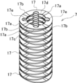
- FIG. 2 is a perspective view showing a bent portion of the bent structure of FIG.
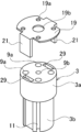
- FIG. 3 is a perspective view showing the relationship between a base and a coupling washer used in the flexure structure of FIG.
- FIG. 4 is an exploded perspective view of the base and coupling washer of FIG.
- FIG. 5 is a perspective view showing the state before machining of the connecting arm of the connecting washer of FIG. 6A and 6B are perspective views showing the manufacture of a bent structure.
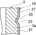
- FIG. 7 is a cross-sectional view showing a part of a bent structure according to a second embodiment of the present invention.
- FIG. 8 is a perspective view showing the relationship between a base portion and an end washer of a bent structure according to a third embodiment of the present invention.
- 9 is an exploded perspective view of the base and mating washer of FIG. 8.
- FIG. 10 is a cross-sectional view of a portion of the base and coupling washer of FIG. 8.
- the objective of making it possible to easily and firmly attach the end member to the bent section is achieved by connecting the connecting arm extending from the bent section to the end member.
- the bending structure 1 comprises a bending portion 7, an end member 3, and a connecting arm 21.
- the bending portion 7 is a member that can be elastically bent in the axial direction.
- the end member 3 is a member that is attached to the axial end of the bending portion 7.
- the connecting arm 21 protrudes in the axial direction from the end of the bending portion 7 and is connected to the end member 3.
- the connecting arm 21 can be connected to the end member 3 by fixing, fitting, engaging, etc., and the connecting arm 21 and the end member 3 can have a configuration according to the connecting mode.
- the end member 3 may have a fixing portion 13 on its outer circumferential surface to which the connecting arm 21 is fixed.
- the connecting arm 21 may be plate-shaped, and the fixing portion 13 may be flat, along which the connecting arm 21 is aligned.
- a plurality of connecting arms 21 may be provided, each of which has elasticity and holds the end member 3.
- a plurality of fixing portions 13 of the end member 3 are provided corresponding to the connecting arms 21, and each is fixed in a state in which the end member 3 is held in elastic contact with the connecting arms 21.
- the end member 3 may have an engagement hole 29 into which the connecting arm 21 is inserted to engage.
- One of the end member 3 and the connecting arm 21 may have a convex portion 23, and the other of the end member 3 and the connecting arm 21 may have a concave portion 25 with which the convex portion 23 engages.
- the bending structure 1 may include a connecting member 19 that forms the end of the bending portion 7, and the connecting arm 21 may be provided on the connecting member 19.
- the bending portion 7 includes a plurality of wave washers 17 that are stacked in the axial direction and maintained in a stacked state by welding, and the connecting member 19 may be a washer that is stacked on the ends of the plurality of wave washers 17 and whose stacked state is maintained by welding.
- the connecting member 19 of such a bending structure 1 may be a washer having a connecting arm 21.
- FIG. 1 is a perspective view showing a bent structure according to a first embodiment of the present invention.
- Fig. 2 is a perspective view showing a bent portion of the bent structure of Fig. 1.
- Fig. 3 is a perspective view showing the relationship between a base and a connecting washer used in the bent structure of Fig. 1.
- Fig. 4 is an exploded perspective view showing the base and the connecting washer of Fig. 3.
- Fig. 5 is a perspective view showing a state before processing of a connecting arm of the connecting washer of Fig. 4.
- the bending structure 1 is applied to the joint function parts of various medical and industrial devices such as manipulators, robots, and actuators.
- the joint function parts are equipment, mechanisms, devices, etc. that function as a bending and extending joint.
- the bending structure 1 of this embodiment includes a base 3, a movable part 5, and a bending part 7.
- the base 3 is a columnar body, such as a cylindrical body, made of metal or resin, and constitutes an end member that is attached to one end in the axial direction of the bending portion 7.
- the axial direction means the direction along the axis of the bending structure 1, and also includes a direction slightly inclined relative to the axis.
- This base 3 is connected to the end of the shaft of a manipulator, etc.
- the base 3 is not limited to a columnar body, and may have an appropriate shape depending on the device to which the bending structure 1 is applied.
- the base 3 in this embodiment is composed of a large diameter section 3a with a relatively large diameter and a small diameter section 3b with a relatively small diameter.
- the large diameter section 3a has multiple, for example, four, insertion holes 9a in the circumferential direction for inserting wires for driving the bending structure 1.
- the inner circumference of the large diameter section 3a has insertion holes 9b for inserting wiring and cables for the end effector of the manipulator.
- the insertion holes 9b also pass through the small diameter section 3b.
- the portion excluding the insertion hole 9b is the outer periphery of the base 3, which is the end member in this embodiment.
- the small diameter portion 3b has a recess 11 corresponding to the insertion hole 9a.
- the circumferential direction refers to the direction along the outer periphery of the bent structure 1.
- This base 3 has a fixing portion 13 on its outer periphery to which a connecting arm 21, described later, is fixed.
- the fixing portion 13 is provided on the outer periphery of the large diameter portion 3a.
- the number of fixing portions 13 is two, but it is also possible to have one or three or more.
- fixing parts 13 are flat, along which the connecting arms 21 are aligned.
- the fixing parts 13 are rectangular flat surfaces that are parallel to each other and aligned along the axial direction of the bending structure 1.
- the fixing portion 13 may be an inclined flat surface that is not aligned along the axial direction.
- the fixing portion 13 may also be a curved surface that is aligned along the circumferential direction, rather than a flat surface.
- the large diameter portion 3a may be a simple cylindrical shape.
- the fixing portions 13 do not need to be parallel to each other. Furthermore, they may be a wavy surface having multiple projections and recesses in the axial direction.
- the movable part 5 is supported by the base part 3 so as to be displaceable in the axial direction by the bending part 7.
- An end effector or the like is attached to this movable part 5 according to the device to which the bending structure 1 is applied.
- the movable part 5 is made of a columnar body, such as a cylindrical body, made of metal or resin, and constitutes an end member that is attached to the other axial end of the bending part 7.
- the other axial end of the bending part 7 refers to the end on the opposite side of the axial direction from the one end to which the base part 3 is attached.
- the movable part 5, like the base part 3, is of an appropriate shape depending on the device to which the bending structure 1 is applied, and is not limited to a columnar body made of metal or resin.
- the movable part 5 has multiple, for example, four, insertion holes 15a in the circumferential direction through which the drive wires of the bending structure 1 are inserted and connected.
- the inner circumference of the movable part 5 has insertion holes 15b through which wiring and cables for the end effector of the manipulator are inserted.
- the movable part 5 may be configured to have a fixing part 13, similar to the base part 3. In this case, it is also possible to omit the fixing part 13 of the base part 3.
- the bending portion 7 includes multiple wave washers 17 and a connecting washer 19 as a connecting member, and is formed into a cylindrical shape as a whole.
- the bending portion 7 may also be a coil spring with a double coil structure, a simple coil spring, or another cylindrical body such as a bellows.
- the bending portion 7 may also be provided with an inner member inside that suppresses axial compression of the coil spring with a double coil structure, etc.
- Multiple wave washers 17 are stacked in the axial direction and maintained in a stacked state.
- the elastic deformation of the wave washers 17 allows them to bend and extend elastically.
- Each wave washer 17 is a plate material formed into a closed or open ring shape from a metal or the like.
- the wave washer 17 is a circular plate material made of stainless steel, and the radial width and plate thickness between the inner and outer periphery are constant.
- the outer diameter of the wave washer 17 in a plan view is approximately the same as the large diameter portion 3a of the base 3 and the movable portion 5.
- the width and plate thickness of the wave washer 17 can also be varied in the circumferential direction.
- This wave washer 17 are joined to adjacent wave washers 17 by welding, for example, laser welding.
- the wave washer 17 has multiple peaks 17a in the circumferential direction, and has valleys 17b between adjacent peaks 17a. Between adjacent wave washers 17 in the axial direction, the peaks 17a of one wave washer 17 abut against the valleys 17b of the other wave washer. These abutting peaks 17a and valleys 17b are joined by laser welding.
- peaks 17a and valleys 17b do not have to abut against each other, and may, for example, be slightly offset from each other in the circumferential direction and abut against the inclined portion 17c.
- the shape and material of the wave washer 17 can be changed as appropriate depending on the required characteristics.
- a through hole 17d is provided on the inner circumference of the wave washer 17, through which wiring and cables for the end effector of the manipulator are passed.
- a plurality of recesses 17e (for example, four recesses) that are concave radially outward in a plan view are provided around the circumferential circumference of the through hole 17d, through which the wires for driving the bending structure 1 are passed.
- the connecting washer 19 is stacked in the axial direction on the ends of the multiple wave washers 17 and is maintained in a stacked state by welding, for example, laser welding. As a result, the connecting washer 19 functions as a connecting member that constitutes the end of the bent portion 7.
- the connecting washer 19 is stacked only on one end of the multiple wave washers 17 to form only one end of the bending portion 7.
- the connecting washer 19 may also be stacked on both ends of the multiple wave washers 17 to form both ends of the bending portion 7.
- This connecting washer 19 is for attaching the base 3, which is an end member, to the axial end of the bent portion 7.
- the connecting washer 19 is a plate material formed into a closed or open ring shape from metal or the like.
- the connecting member can be any shape, including a wave washer, in addition to the connecting washer 19, which is a flat washer.
- the connecting washer 19 is a flat washer made of stainless steel and is an annular plate material, with a constant radial width and plate thickness between the inner and outer periphery.
- the outer diameter of the connecting washer 19 is approximately the same as the outer diameter of the wave washer 17 in a plan view. Note that the outer diameter of the connecting washer 19 refers to the portion where the connecting arm 21 described below is not provided.
- This connecting washer 19 has multiple, for example four, insertion holes 19a in the circumferential direction for inserting the wires for driving the bending structure 1.
- the inner circumference of the connecting washer 19 has insertion holes 19b for inserting wiring and cables for the end effector of the manipulator.
- a connecting arm 21 is provided on the outer circumference of the connecting washer 19.
- the connecting arm 21 protrudes axially from the end of the bent portion 7 and is connected to the base portion 3.
- connecting arm 21 does not need to be protruded in the axial direction along the connecting arm 21, but rather the tip of the connecting arm 21 needs to be in a position offset in the axial direction relative to the base end.
- the connecting arm 21 is a flat plate that is positioned along the planar fixing portion 13 of the base 3. For this reason, multiple connecting arms 21 are provided on the outer periphery of the connecting washer 19 in correspondence with the fixing portion 13 of the base 3.
- connecting arms 21 extend in parallel along the axial direction.
- the connecting arms 21 can also be in the shape of a flat plate inclined together with the fixing portion 13, rather than along the axial direction.
- the connecting arms 21 do not have to be parallel to each other depending on the fixing portion 13.
- the connecting arms 21 do not have to be flat, and can be a corrugated plate having multiple projections and recesses in the axial direction.
- the connecting arms 21 can adopt various shapes other than a plate shape, such as a rod shape, a cylinder shape, a bowl shape, etc.
- the connecting arm 21 only needs to be provided in correspondence with the fixing portion 13, and may be located on the connecting washer 19 at a position other than the outer circumferential edge.
- the connecting washer 19 may be formed with a larger diameter than the base 3, and the connecting arm 21 may be provided in the outer circumferential region that protrudes radially from the base 3.
- the outer circumferential region itself may also be used as the connecting arm.
- the planar shape of the connecting arm 21 is rectangular, but it may be another geometric shape. Note that the planar shape refers to the shape when viewed from the thickness direction of the connecting arm 21.
- the axial length of the connecting arm 21 is the same as the length of the fixing portion 13, and the width of the connecting arm 21 is shorter than the width of the fixing portion 13. Note that the length of the connecting arm 21 may be shorter or longer than the length of the fixing portion 13, and the width of the connecting arm 21 may be the same as or longer than the width of the fixing portion 13.
- Each of the connecting arms 21 has elasticity. As a result, the connecting arms 21 elastically contact the fixing portion 13 of the base 3 and are fixed to the fixing portion 13 while holding the base 3. As a result, the connecting arms 21 in this embodiment are connected to the outer periphery of the base 3. However, as long as the connecting arms 21 can be connected to the base 3, the connection point to the base 3 does not necessarily have to be the outer periphery.
- elastic contact means elastic contact, but the connecting arms 21 do not need to be in elastic contact with the base 3. Also, while there are two connecting arms 21, it is possible to have one or three or more connecting arms 21, including the fixing part 13.
- the connecting arm 21 and the fixing portion 13 are fixed by welding.
- the connection between the base 3 and the connecting arm 21 is achieved by the connection between the connecting arm 21 and the fixing portion 13 and the elastic contact of the connecting arm 21 with the fixing portion 13. Therefore, the bending portion 7 and the base 3 can be fixed firmly.
- the fixing between the connecting arm 21 and the fixing portion 13 can be achieved by reducing the fixing force by the elastic contact of the connecting arm 21 with the fixing portion 13, so that the fixing force is weaker than that achieved by welding.
- the fixing may be achieved by gluing, soldering, etc.
- the connecting arm 21 is attached to the fixing portion 13 at the center of the connecting arm 21.
- the connecting arm 21 is attached by welding as in this embodiment, it is sufficient that part or all of the weld mark is located within the rectangular shape of the connecting arm 21 as long as the connection strength can be ensured.
- the connecting arm 21 allows the fixing point to be selected as appropriate.
- the connecting arm 21 can be easily formed by punching out the connecting arm 21 together with the connecting washer 19 using a press or the like, as shown in Figure 5, and then bending it to make it stand up.
- FIG. 6A and 6B are perspective views showing the manufacture of the bent structure 1.
- FIG. 6A and 6B are perspective views showing the manufacture of the bent structure 1.
- a plurality of wave washers 17 are stacked on the movable part 5 to form the bending part 7, and then the base part 3 is attached to the end of the formed bending part 7.
- Laser welding is performed by irradiating a laser beam from above each wave washer 17 that is stacked. This bonds the movable part 5 and the wave washer 17, and also bonds adjacent wave washers 17 together.
- the laser beam may be any suitable type, such as a carbon dioxide laser, a YAG (Yttrium Aluminum Garnet) laser, or a fiber laser.
- a connecting washer 19 is stacked in the axial direction on top of the stacked wave washers 17, and the stacked state is maintained by axial laser welding. This forms the bent portion 7. In this state, the connecting arm 21 protrudes in the axial direction from the end of the bent portion 7.
- the base 3 is inserted between the protruding connecting arms 21. That is, the axial end of the fixing portion 13 of the base 3 is aligned with the axial end of the connecting arm 21, and in this state the base 3 is inserted axially between the connecting arms 21. At this time, the fixing portion 13 slides relative to the connecting arm 21, guiding the insertion of the base 3.
- the connecting arm 21 can ensure an irradiation area of the laser beam for laser welding, and laser welding between the connecting arm 21 and the fixing portion 13 can be performed reliably.
- the fixing portion 13 is flat to which the connecting arm 21 is aligned, laser welding between the connecting arm 21 and the fixing portion 13 can be performed more reliably.
- the base 3 has the fixing portion 13 to which the connecting arm 21 is fixed on its outer circumferential surface, laser welding with the connecting arm 21 can be performed easily and reliably.
- the base 3 is joined to the end of the bent portion 7, completing the bent structure 1 of FIG. 1.
- the connecting arm 21 extending from the bent portion 7 is joined to the outer periphery of the base 3, which is the end member, making it possible to easily and firmly attach the base 3 to the bent portion 7 by laser welding.
- the formation of the bent portion 7 on the movable portion 5 and the attachment of the base portion 3 can all be performed by laser welding, making it easy to manufacture the bent structure 1.
- the bending structure 1 may be required to have a smaller diameter, but even if the diameter is reduced, sufficient fixation can be achieved between the connecting arm 21 and the fixing portion 13. Therefore, the bending structure 1 of this embodiment can accommodate a smaller diameter.
- FIG. 7 is a cross-sectional view showing a portion of a bent structure according to a second embodiment of the present invention. Note that in the second embodiment, the same reference numerals are used for configurations corresponding to those in the first embodiment, and duplicated descriptions are omitted.
- the bending structure 1 of this embodiment is such that the connecting arm 21 and the base 3 are connected by engaging the convex portion 23 and the concave portion 25.
- the rest is the same as in Example 1.
- the convex portion 23 is formed by partially curving the flat connecting arm 21.
- the curved convex portion 23 may be formed in advance on the connecting arm 21 by pressing or the like, or may be formed when connecting the connecting arm 21 to the base 3 by crimping or the like.
- the shape of the convex portion 23 is not particularly limited, and may be, for example, a partially increased plate thickness of the connecting arm 21.
- the recess 25 is formed in the engagement portion 27 of the base 3.
- the engagement portion 27 has the same planar configuration as the fixing portion 13 of the first embodiment, except for the recess 25.
- the recess 25 is provided corresponding to the protrusion 23, and the protrusion 23 is inserted into the recess 25 to engage with it.
- FIG. 8 is a perspective view showing the relationship between the base and end washers of a bent structure according to Example 3 of the present invention.
- FIG. 9 is an exploded perspective view of the base and end washers of FIG. 8.
- FIG. 10 is a cross-sectional view showing a portion of the base and end washer of FIG. 8. Note that in Example 3, the same reference numerals are used for configurations corresponding to those in Example 1, and duplicated explanations will be omitted.
- the bending structure 1 of this embodiment has an engagement hole 29 in the base 3 into which the connecting arm 21 is inserted and engaged.
- the engagement hole 29 is provided axially through the large diameter portion 3a of the base 3.
- the cross-sectional shape of the engagement hole 29 is formed to be larger than the cross-sectional shape of the connecting arm 21.
- the connecting arm 21 has a claw portion 31 at its tip.
- the claw portion 31 is formed to protrude radially from the connecting arm 21.
- the connecting arm 21 is formed to be longer in the axial direction than the engagement hole 29, and the claw portion 31 at the tip protruding outward from the engagement hole 29 engages with the opening edge portion 29a of the engagement hole 29.
- the connecting arm 21 may also omit the claw portion 31.
- the connecting arm 21 may be configured to fit into the engagement hole 29.
- the connecting arm 21 may be provided between the inner and outer periphery of the connecting washer 19.
- the engagement hole 29 is provided at a position biased toward the inner periphery in correspondence with the connecting arm 21.
- the bent portion 7 and the base portion 3 can be joined more easily.
Landscapes
- Engineering & Computer Science (AREA)
- General Engineering & Computer Science (AREA)
- Mechanical Engineering (AREA)
- Robotics (AREA)
- Pivots And Pivotal Connections (AREA)
- Connection Of Plates (AREA)
- Clamps And Clips (AREA)
- Manipulator (AREA)
- Bolts, Nuts, And Washers (AREA)
- Snaps, Bayonet Connections, Set Pins, And Snap Rings (AREA)
Abstract
端部部材を屈曲部に簡易且つ強固に取り付けることを可能とすることが可能な屈曲構造体を提供する。軸方向に対して弾性的に屈曲可能な屈曲部7と、屈曲部7の軸方向の端部に取り付けられる基部3と、屈曲部7の端部に軸方向に突設され、基部3に結合される結合アーム21と、を備える。
Description
本発明は、ロボットやマニピュレーター等の関節機能部に供される屈曲構造体及びこの屈曲構造体に用いられるワッシャーに関する。
従来の屈曲構造体としては、特許文献1のように、屈曲可能な屈曲部の軸方向の端部に端部部材を取り付けたものが知られている。
屈曲部は、複数のウェーブワッシャーを積層すると共に、この積層状態がウェーブワッシャー相互間をレーザー溶接することで保持されて形成される。
屈曲部には、端部部材が更に積層されて取り付けられる。端部部材の屈曲部への取付けでは、レーザー溶接を用いれば、簡易な工程で強固な結合が得ることができる。
しかし、屈曲部と端部部材との間は、積層方向からレーザー光を照射することができないので、側方からレーザー光を照射する必要があり、十分な結合強度が得られなかった。
こうした問題は、屈曲部が積層したウェーブワッシャーである場合だけでなく、コイルばねやベローズ等の他の屈曲部においても同様に生じていた。
解決しようとする問題点は、屈曲部の軸方向の端部に端部部材を簡易且つ強固に取り付けることができなかった点である。
本発明は、軸方向に対して弾性的に屈曲可能な屈曲部と、該屈曲部の前記軸方向の端部に取り付けられる端部部材と、前記屈曲部の前記端部に前記軸方向に突設され前記端部部材に結合される結合アームと、を備える屈曲構造体を提供する。
また、本発明は、軸方向に対して弾性的に屈曲可能な屈曲部の前記軸方向の端部に端部部材を取り付けるためのワッシャーであって、前記軸方向に突設され前記端部部材に結合される結合アームを備えた、ワッシャーを提供する。
本発明によれば、屈曲部から延設された結合アームを端部部材に結合するため、端部部材を屈曲部に簡易且つ強固に取り付けることを可能とする。
端部部材を屈曲部に簡易且つ強固に取り付けることを可能とするという目的を、屈曲部から延設された結合アームを端部部材に結合することにより実現した。
屈曲構造体1は、屈曲部7と、端部部材3と、結合アーム21とを備える。屈曲部7は、軸方向に対して弾性的に屈曲可能な部材である。端部部材3は、屈曲部7の軸方向の端部に取り付けられる部材である。結合アーム21は、屈曲部7の端部に軸方向に突設され端部部材3に結合される。
結合アーム21の端部部材3への結合態様は、固着、嵌合、係合等があり、結合アーム21及び端部部材3は、結合態様に応じた構成を有すればよい。
端部部材3は、結合アーム21が固着される固着部13を外周面上に有してもよい。
この場合、結合アーム21は、板状であり、固着部13は、結合アーム21を沿わせる平面状である構成としてもよい。
さらに、結合アーム21は、複数設けられ、それぞれ弾性を有して端部部材3を保持してもよい。この場合、端部部材3の固着部13は、結合アーム21に応じて複数設けられ、それぞれ結合アーム21を弾接させた端部部材3の保持状態で固着される。
端部部材3は、結合アーム21を挿入により係合させる係合孔29を有してもよい。
端部部材3及び結合アーム21の一方は、凸部23を有し、端部部材3及び結合アーム21の他方は、凸部23を係合させる凹部25を有する構成としてもよい。
屈曲構造体1は、屈曲部7の端部を構成する結合部材19を備え、結合アーム21は、結合部材19に設けられた構成としてもよい。
屈曲部7は、軸方向に積層されると共に溶接によって積層状態が保持された複数のウェーブワッシャー17を備え、結合部材19は、複数のウェーブワッシャー17の端部に積層されると共にその積層状態が溶接によって保持されるワッシャーであってもよい。
かかる屈曲構造体1の結合部材19は、結合アーム21を備えるワッシャーであってもよい。
[屈曲構造体の構成]
図1は、本発明の実施例1に係る屈曲構造体を示す斜視図である。図2は、図1の屈曲構造体の屈曲部を示す斜視図である。図3は、図1の屈曲構造体に用いられる基部と結合ワッシャーとの関係を示す斜視図である。図4は、図3の基部と結合ワッシャーとを示す分解斜視図である。図5は、図4の結合ワッシャーの結合アームの加工前の状態を示す斜視図である。
図1は、本発明の実施例1に係る屈曲構造体を示す斜視図である。図2は、図1の屈曲構造体の屈曲部を示す斜視図である。図3は、図1の屈曲構造体に用いられる基部と結合ワッシャーとの関係を示す斜視図である。図4は、図3の基部と結合ワッシャーとを示す分解斜視図である。図5は、図4の結合ワッシャーの結合アームの加工前の状態を示す斜視図である。
屈曲構造体1は、マニピュレーター、ロボット、アクチュエーターのような医療用や産業用等の各種の機器の関節機能部に適用されるものである。関節機能部は、屈曲・伸展する関節としての機能を有する装置、機構、デバイス等である。
本実施例の屈曲構造体1は、基部3と、可動部5と、屈曲部7とを備えている。
基部3は、金属や樹脂等で形成された柱状体、例えば円柱状体からなり、屈曲部7の軸方向の一方の端部に取り付けられる端部部材を構成する。軸方向とは、屈曲構造体1の軸心に沿った方向を意味し、軸心に対して僅かに傾斜した方向も含む。
この基部3は、マニピュレーターのシャフトの端部等に結合される。なお、基部3は、柱状体に限られず、屈曲構造体1が適用される機器に応じて適宜の形態とする。
本実施例の基部3は、相対的に大径の大径部3aと相対的に小径の小径部3bとで構成されている。大径部3aには、屈曲構造体1の駆動用のワイヤーを挿通する挿通孔9aが周方向に複数、例えば4つ設けられている。大径部3aの内周には、マニピュレーターのエンドエフェクタ用の配線やケーブルを挿通する挿通孔9bが設けられている。挿通孔9bは、小径部3bも貫通する。
この挿通孔9bを除く部分が本実施例において端部部材である基部3の外周部となる。小径部3bは、挿通孔9aに対応して凹部11を備えている。周方向とは、屈曲構造体1の外周に沿った方向をいう。
この基部3は、後述する結合アーム21が固着される固着部13を外周面上に有する。本実施例では、大径部3aの外周面上に固着部13が設けられている。固着部13の数は、二つとなっているが、一つ又は三つ以上とすることも可能である。
これら固着部13は、それぞれ結合アーム21を沿わせる平面状となっている。本実施例の固着部13は、屈曲構造体1の軸方向に沿うと共に相互に平行な矩形平面からなる。
なお、固着部13は、軸方向に沿わずに、傾斜した平面状とすることも可能である。また、固着部13は、平面ではなく、周方向に沿った曲面であってもよい。固着部13が周方向に沿った曲面の場合は、大径部3aを単純な円柱形状とすればよい。また、固着部13は、相互に平行である必要はない。さらに、軸方向に複数の凹凸を有する波形状の面等であってもよい。
可動部5は、屈曲部7により、軸方向に対して変位可能に基部3に支持される。この可動部5には、屈曲構造体1が適用される機器に応じたエンドエフェクタ等が取り付けられる。
かかる可動部5は、金属や樹脂等によって形成された柱状体、例えば円柱状体からなり、屈曲部7の軸方向の他方の端部に取り付けられる端部部材を構成する。なお、屈曲部7の軸方向の他方の端部は、基部3が取り付けられる一方の端部に対する軸方向の反対側の端部をいう。可動部5は、基部3と同様、屈曲構造体1が適用される機器に応じて適宜の形態とされ、金属や樹脂等による柱状体に限られるものではない。
可動部5には、屈曲構造体1の駆動用のワイヤーを挿通状態で結合する挿通孔15aが周方向に複数、例えば4つ設けられている。可動部5の内周には、マニピュレーターのエンドエフェクタ用の配線やケーブルを挿通する挿通孔15bが設けられている。
なお、可動部5は、基部3と同様に固着部13を有する構成としてもよい。この場合、基部3の固着部13を省略することも可能である。
屈曲部7は、複数のウェーブワッシャー17と、結合部材としての結合ワッシャー19とを備え、全体として筒状に形成されている。なお、屈曲部7は、二重コイル構造のコイルばね、単純なコイルばね、或いはベローズ等の他の筒状体を採用してもよい。また、屈曲部7は、内部に二重コイル構造のコイルばね等の軸方向の圧縮を抑制するインナー部材を備えてもよい。
複数のウェーブワッシャー17は、軸方向で積層されると共に積層状態が保持されている。ウェーブワッシャー17の弾性変形により、弾性的に屈曲及び伸展が可能となっている。
各ウェーブワッシャー17は、金属等によって閉または開環状に形成された板材である。本実施例のウェーブワッシャー17は、ステンレスからなる円環状の板材であり、内外周間の径方向の幅及び板厚が一定となっている。ウェーブワッシャー17の平面視における外径は、基部3の大径部3a及び可動部5と同程度となっている。なお、ウェーブワッシャー17の幅及び板厚は、周方向で変動させることも可能である。
このウェーブワッシャー17は、隣接するウェーブワッシャー17に対して当接部分が溶接、例えばレーザー溶接によって結合されている。
本実施例において、ウェーブワッシャー17は、周方向に複数の山部17aを有し、隣接する山部17a間に谷部17bを有する。軸方向で隣接するウェーブワッシャー17間では、一方のウェーブワッシャー17の山部17aが他方のウェーブワッシャーの谷部17bに当接している。これら当接する山部17a及び谷部17bが、レーザー溶接によって結合されている。
なお、山部17a及び谷部17bは、相互に当接しなくてもよく、例えば、相互に若干周方向にずれて傾斜部17cに当接する形態としてもよい。また、ウェーブワッシャー17の形状や材質等は、要求される特性等に応じて適宜変更することが可能である。
ウェーブワッシャー17の内周には、マニピュレーターのエンドエフェクタ用の配線やケーブルを挿通する挿通孔17dが設けられている。この挿通孔17dに対し、平面視において径方向の外側へ凹状となる凹部17eが周方向に複数、例えば4つ設けられ、屈曲構造体1の駆動用のワイヤーを挿通するようになっている。
結合ワッシャー19は、複数のウェーブワッシャー17の端部に軸方向で積層されると共に溶接、例えばレーザー溶接によって積層状態が保持されている。これにより、結合ワッシャー19は、屈曲部7の端部を構成する結合部材として機能する。
本実施例において、結合ワッシャー19は、複数のウェーブワッシャー17の一方の端部にのみ積層されて屈曲部7の一端部のみを構成している。ただし、結合ワッシャー19は、複数のウェーブワッシャー17の両端部に積層されて屈曲部7の両端部を構成してもよい。
この結合ワッシャー19は、屈曲部7の軸方向の端部に端部部材である基部3を取り付けるためのものである。本実施例の結合ワッシャー19は、金属等によって閉または開環状に形成された板材である。なお、結合部材は、平ワッシャーである結合ワッシャー19の他、ウェーブワッシャー等を採用することも可能であり、形態は自由である。
本実施例の結合ワッシャー19は、ステンレスからなる円環状の板材としての平ワッシャーであり、内外周間の径方向の幅及び板厚が一定となっている。結合ワッシャー19の外径は、ウェーブワッシャー17の平面視における外径と同程度となっている。なお、結合ワッシャー19の外径は、後述する結合アーム21が設けられていない部分でのものをいう。
この結合ワッシャー19は、屈曲構造体1の駆動用のワイヤーを挿通する挿通孔19aが周方向に複数、例えば4つ設けられている。結合ワッシャー19の内周には、マニピュレーターのエンドエフェクタ用の配線やケーブルを挿通する挿通孔19bが設けられている。結合ワッシャー19の外周には、結合アーム21が設けられている。
結合アーム21は、屈曲部7の端部に軸方向に突設され、基部3に結合されるものである。
なお、結合アーム21の軸方向への突設は、結合アーム21が軸方向に沿って行われる必要はなく、結合アーム21の先端が基端に対して軸方向で偏倚した位置にあるように行われればよい。
本実施例の結合アーム21は、基部3の平面状の固着部13に沿って位置する平板である。このため、結合アーム21は、基部3の固着部13に対応して結合ワッシャー19の外周縁に複数設けられている。
これら結合アーム21は、軸方向に沿って平行に延設されている。ただし、結合アーム21は、軸方向に沿わずに、固着部13と共に傾斜した平板状とすることも可能である。また、結合アーム21は、固着部13に応じて相互に平行である必要はない。また結合アーム21は、平板である必要はなく、軸方向に複数の凹凸を有する波形状の板等であってもよい。また、結合アーム21は、板状以外にも、棒状、筒状、椀状等の各種の形態を採用可能である。
なお、結合アーム21は、固着部13に対応して設けられればよいので、結合ワッシャー19上での位置を外周縁以外としてもよい。例えば、結合ワッシャー19を基部3よりも大径に形成し、基部3から径方向にはみ出した外周領域に結合アーム21を設けることも可能である。また、外周領域自体を結合アームとしてもよい。
本実施例において、結合アーム21の平面形状は、矩形状となっているが、他の幾何学形状であってもよい。なお、平面形状は、結合アーム21の厚み方向から見た形状をいう。
結合アーム21の軸方向の長さは、固着部13の長さと同一であり、結合アーム21の幅は、固着部13の幅よりも短い。なお、結合アーム21の長さは、固着部13の長さよりも短く又は長くしてもよく、結合アーム21の幅は、固着部13の幅と同一かそれよりも長くしてもよい。
結合アーム21は、それぞれ弾性を有している。これにより、結合アーム21は、基部3の固着部13に弾接し、基部3を保持した状態で固着部13に固着される。これにより、本実施例の結合アーム21は、基部3の外周部に結合されている。ただし、結合アーム21は、基部3に結合できればよいので、基部3に対する結合箇所は、必ずしも外周部でなくてよい。
なお、弾接は、弾性をもって当接することであるが、結合アーム21は、基部3に弾接する必要はない。また、結合アーム21の数は、二つとなっているが、固着部13と共に一つ又は三つ以上とすることも可能である。
結合アーム21と固着部13との固着は、溶接によって行われている。本実施例では、基部3と結合アーム21との結合を、結合アーム21と固着部13との固着並びに結合アーム21の固着部13への弾接で担っている。従って、屈曲部7と基部3とを強固に結合することができる。また、結合アーム21と固着部13との固着は、結合アーム21の固着部13への弾接の分だけ固着力を低減させ、溶接よりも固着力の弱い固着とすることも可能である。例えば、固着は、接着やはんだ付け等であってもよい。
結合アーム21の固着部13への固着箇所は、結合アーム21の中心部である。ただし、結合アーム21の固着箇所は、本実施例のように溶接で結合アーム21の固着が行われる場合、結合強度を確保できる限りにおいて、溶接痕の一部又は全部が結合アーム21の矩形形状の範囲内に位置すればよい。つまり、結合アーム21は、固着箇所を適宜選択可能とする。
結合アーム21の形成は、図5のように、プレス等によって結合ワッシャー19と一体に結合アーム21を打抜いた後、曲げ加工によって起立されることで容易に行うことができる。
[屈曲構造体の製造]
図6(A)及び(B)は、屈曲構造体1の製造を示す斜視図である。
図6(A)及び(B)は、屈曲構造体1の製造を示す斜視図である。
本実施例の屈曲構造体1の製造では、可動部5に対して複数のウェーブワッシャー17を積み上げて屈曲部7を形成した後、形成された屈曲部7の端部に基部3を取り付ける。ただし、基部3に対してウェーブワッシャー17を積み上げて屈曲部7を形成し、屈曲部7の端部に可動部5を取り付けてもよい。
本実施例の屈曲部7の形成では、図6(A)のように、まず可動部5上に複数のウェーブワッシャー17を軸方向で積層し、レーザー溶接によって積層状態を保持する。
レーザー溶接は、ウェーブワッシャー17を積層する度に、その上からレーザー光を照射することで行われる。これにより、可動部5とウェーブワッシャー17との間及び隣接するウェーブワッシャー17間が結合される。なお、レーザー光は、炭酸ガスレーザー、YAG(Yttrium Aluminum Garnet)レーザー、ファイバーレーザー等の適宜のものを採用すればよい。
次いで、図6(B)のように、積層された複数のウェーブワッシャー17上に軸方向で結合ワッシャー19を積層し、軸方向からのレーザー溶接によって積層状態を保持する。これにより、屈曲部7が形成される。この状態では、結合アーム21が屈曲部7の端部から軸方向に突出している。
突出する結合アーム21間には基部3を挿入する。すなわち、結合アーム21の軸方向の端部に基部3の固着部13の軸方向の端部を合わせておき、この状態で基部3を結合アーム21間へ軸方向で挿入する。このとき、結合アーム21に対して固着部13がスライドし、基部3の挿入を案内することができる。
この挿入により基部3が結合ワッシャー19に軸方向で突き当たると、結合アーム21を固着部13にレーザー溶接により固着する。
このとき、結合アーム21によってレーザー溶接のレーザー光の照射領域を確保することができ、結合アーム21と固着部13とのレーザー溶接を確実に行うことができる。また、固着部13は、結合アーム21を沿わせる平面状であるため、結合アーム21と固着部13とのレーザー溶接をより確実に行うことができる。しかも、基部3は、結合アーム21が固着される固着部13を外周面上に有するので、結合アーム21とのレーザー溶接を容易且つ確実に行うことができる。
こうして屈曲部7の端部に基部3が結合されて図1の屈曲構造体1が完成する。このように、本実施例では、屈曲部7から延設された結合アーム21を端部部材である基部3の外周部に結合するため、レーザー溶接によって基部3を屈曲部7に簡易且つ強固に取り付けることを可能とする。
この結果、可動部5上での屈曲部7の形成並びに基部3の取付けを全てレーザー溶接で行うことができ、屈曲構造体1の製造を容易に行うことができる。
また、屈曲構造体1は、小径化が求められることがあるが、小径化しても結合アーム21と固着部13との十分な固着を行わせることができる。従って、本実施例の屈曲構造体1は、小径化に対応することが可能である。
図7は、本発明の実施例2に係る屈曲構造体の一部を示す断面図である。なお、実施例2は、実施例1と対応する構成に同符号を付して重複した説明を省略する。
本実施例の屈曲構造体1は、結合アーム21と基部3との結合を凸部23と凹部25との係合によって行ったものである。その他は、実施例1と同様である。
凸部23は、平板状の結合アーム21に部分的な湾曲によって形成されている。湾曲による凸部23は、予めプレス等によって結合アーム21に形成するか、或いはカシメ等によって結合アーム21を基部3に結合する際に形成すればよい。なお、凸部23の形状は、特に限定されるものではなく、例えば結合アーム21の板厚を部分的に増加させたものであってもよい。
凹部25は、基部3の係合部27に形成されている。係合部27は、凹部25を除き、実施例1の固着部13と同一の平面状の構成となっている。凹部25は、凸部23に対応して設けられ、凸部23を入れ込んで係合させる。
かかる実施例2では、実施例1と同様の作用効果を奏することができるのに加え、屈曲部7と基部3との結合をより簡易に行うことができる。
図8は、本発明の実施例3に係る屈曲構造体の基部及び端部ワッシャーの関係を示す斜視図である。図9は、図8の基部及び端部ワッシャーの分解斜視図である。図10は、図8の基部及び端部ワッシャーの一部を示す断面図である。なお、実施例3は、実施例1と対応する構成に同符号を付して重複した説明を省略する。
本実施例の屈曲構造体1は、基部3が結合アーム21を挿入により係合させる係合孔29を有する。
係合孔29は、基部3の大径部3aに軸方向に貫通して設けられている。係合孔29の断面形状は、結合アーム21の断面形状よりも大きく形成されている。
結合アーム21は、先端に爪部31を有する。爪部31は、結合アーム21径方向に突出して形成されている。結合アーム21は、係合孔29よりも軸方向に長く形成されており、係合孔29から外部に突出した先端の爪部31が係合孔29の開口縁部29aに係合する。
なお、結合アーム21は、爪部31を省略することも可能である。この場合、結合アーム21は、係合孔29内に嵌合する構成とすればよい。また、結合アーム21は、結合ワッシャー19の外周縁に代えて、結合ワッシャー19の内周と外周との間に設けてもよい。この場合、係合孔29は、結合アーム21に対応して内周側に偏倚した位置に設けられる。
かかる実施例3においても、実施例1と同様の作用効果を奏することができるのに加え、屈曲部7と基部3との結合をより簡易に行うことができる。
1 屈曲構造体
3 基部(端部部材)
5 可動部(端部部材)
7 屈曲部
13 固着部
17 ウェーブワッシャー
19 端部ワッシャー(結合部材)
21 結合アーム
23 凸部
25 凹部
29 係合孔
3 基部(端部部材)
5 可動部(端部部材)
7 屈曲部
13 固着部
17 ウェーブワッシャー
19 端部ワッシャー(結合部材)
21 結合アーム
23 凸部
25 凹部
29 係合孔
Claims (9)
- 軸方向に対して弾性的に屈曲可能な屈曲部と、
該屈曲部の前記軸方向の端部に取り付けられる端部部材と、
前記屈曲部の前記端部に前記軸方向に突設され前記端部部材に結合される結合アームと
、
を備える屈曲構造体。 - 請求項1の屈曲構造体であって、
前記端部部材は、前記結合アームが固着される固着部を外周面上に有する、
屈曲構造体。 - 請求項2の屈曲構造体であって、
前記結合アームは、板状であり、
前記固着部は、前記結合アームを沿わせる平面状である、
屈曲構造体。 - 請求項3の屈曲構造体であって、
前記結合アームは、複数設けられ、それぞれ弾性を有して前記端部部材を保持し、
前記端部部材の固着部は、前記結合アームに応じて複数設けられ、それぞれ前記結合アームを弾接させた前記端部部材の保持状態で固着される、
屈曲構造体。 - 請求項1の屈曲構造体であって、
前記端部部材は、前記結合アームを挿入により係合させる係合孔を有する、
屈曲構造体。 - 請求項1の屈曲構造体であって、
前記端部部材及び前記結合アームの一方は、凸部を有し、
前記端部部材及び前記結合アームの他方は、前記凸部を係合させる凹部を有する、
屈曲構造体。 - 請求項1~6の何れか一項の屈曲構造体であって、
前記屈曲部の前記端部を構成する結合部材を備え、
前記結合アームは、前記結合部材に設けられた、
屈曲構造体。 - 請求項7の屈曲構造体であって、
前記屈曲部は、前記軸方向に積層されると共に溶接によって積層状態が保持された複数のウェーブワッシャーを備え、
前記結合部材は、前記複数のウェーブワッシャーの端部に積層されると共に該積層状態が溶接によって保持されるワッシャーである、
屈曲構造体。 - 軸方向に対して弾性的に屈曲可能な屈曲部の前記軸方向の端部に端部部材を取り付けるためのワッシャーであって、
前記軸方向に突設され前記端部部材の外周部に結合される結合アームを備えた、
ワッシャー。
Applications Claiming Priority (2)
| Application Number | Priority Date | Filing Date | Title |
|---|---|---|---|
| JP2022-153025 | 2022-09-26 | ||
| JP2022153025A JP2024047417A (ja) | 2022-09-26 | 2022-09-26 | 屈曲構造体及びワッシャー |
Publications (1)
| Publication Number | Publication Date |
|---|---|
| WO2024071102A1 true WO2024071102A1 (ja) | 2024-04-04 |
Family
ID=90477999
Family Applications (1)
| Application Number | Title | Priority Date | Filing Date |
|---|---|---|---|
| PCT/JP2023/034899 Ceased WO2024071102A1 (ja) | 2022-09-26 | 2023-09-26 | 屈曲構造体及びワッシャー |
Country Status (3)
| Country | Link |
|---|---|
| JP (1) | JP2024047417A (ja) |
| TW (1) | TW202413029A (ja) |
| WO (1) | WO2024071102A1 (ja) |
Citations (3)
| Publication number | Priority date | Publication date | Assignee | Title |
|---|---|---|---|---|
| JPH03100362U (ja) * | 1990-01-31 | 1991-10-21 | ||
| JPH0454111U (ja) * | 1990-09-13 | 1992-05-08 | ||
| JP2020172002A (ja) * | 2019-04-11 | 2020-10-22 | 日本発條株式会社 | 可撓部材 |
-
2022
- 2022-09-26 JP JP2022153025A patent/JP2024047417A/ja active Pending
-
2023
- 2023-09-26 WO PCT/JP2023/034899 patent/WO2024071102A1/ja not_active Ceased
- 2023-09-26 TW TW112136708A patent/TW202413029A/zh unknown
Patent Citations (3)
| Publication number | Priority date | Publication date | Assignee | Title |
|---|---|---|---|---|
| JPH03100362U (ja) * | 1990-01-31 | 1991-10-21 | ||
| JPH0454111U (ja) * | 1990-09-13 | 1992-05-08 | ||
| JP2020172002A (ja) * | 2019-04-11 | 2020-10-22 | 日本発條株式会社 | 可撓部材 |
Also Published As
| Publication number | Publication date |
|---|---|
| TW202413029A (zh) | 2024-04-01 |
| JP2024047417A (ja) | 2024-04-05 |
Similar Documents
| Publication | Publication Date | Title |
|---|---|---|
| JP5647226B2 (ja) | 付勢された暫定ファスナー | |
| US12594680B2 (en) | Flexible structure and method for producing same | |
| JP7055766B2 (ja) | 可撓部材 | |
| WO2020209388A1 (ja) | 可撓部材 | |
| WO2024071102A1 (ja) | 屈曲構造体及びワッシャー | |
| JP7055767B2 (ja) | 可撓部材 | |
| US12337469B2 (en) | Flexible structure | |
| WO2022230976A1 (ja) | 屈曲構造体及びその製造方法 | |
| US20110290054A1 (en) | Pinion clip for right angle linear cutter | |
| JP2022145753A (ja) | ウェーブワッシャー | |
| JPH0392610A (ja) | 二部材結合具 | |
| JP7680066B2 (ja) | コイルばねの保持構造およびコイルばねの保持方法 | |
| JP2022089898A (ja) | 可撓部材 | |
| JP2005287167A (ja) | 駆動装置 | |
| JPH10184913A (ja) | ブーツ | |
| JP4106575B2 (ja) | 積層型圧電アクチュエータ | |
| JPH0348022A (ja) | 板バネ式自在継手 | |
| JP6355268B2 (ja) | 嵌合構造及び被嵌合部材の製造方法 | |
| JP2024147152A (ja) | アクチュエータ | |
| JP2021136781A (ja) | アクチュエータ | |
| JPH03125022A (ja) | 玉型自在継手の組立方法 | |
| JP2019086071A (ja) | 結合構造とその結合方法 |
Legal Events
| Date | Code | Title | Description |
|---|---|---|---|
| 121 | Ep: the epo has been informed by wipo that ep was designated in this application |
Ref document number: 23872325 Country of ref document: EP Kind code of ref document: A1 |
|
| NENP | Non-entry into the national phase |
Ref country code: DE |
|
| 122 | Ep: pct application non-entry in european phase |
Ref document number: 23872325 Country of ref document: EP Kind code of ref document: A1 |