WO2024070976A1 - 血管穿刺装置 - Google Patents
血管穿刺装置 Download PDFInfo
- Publication number
- WO2024070976A1 WO2024070976A1 PCT/JP2023/034583 JP2023034583W WO2024070976A1 WO 2024070976 A1 WO2024070976 A1 WO 2024070976A1 JP 2023034583 W JP2023034583 W JP 2023034583W WO 2024070976 A1 WO2024070976 A1 WO 2024070976A1
- Authority
- WO
- WIPO (PCT)
- Prior art keywords
- puncture device
- puncture
- backflow
- blood vessel
- blood
- Prior art date
- Legal status (The legal status is an assumption and is not a legal conclusion. Google has not performed a legal analysis and makes no representation as to the accuracy of the status listed.)
- Ceased
Links
Images




Classifications
-
- A—HUMAN NECESSITIES
- A61—MEDICAL OR VETERINARY SCIENCE; HYGIENE
- A61B—DIAGNOSIS; SURGERY; IDENTIFICATION
- A61B17/00—Surgical instruments, devices or methods
- A61B17/34—Trocars; Puncturing needles
- A61B17/3403—Needle locating or guiding means
-
- A—HUMAN NECESSITIES
- A61—MEDICAL OR VETERINARY SCIENCE; HYGIENE
- A61B—DIAGNOSIS; SURGERY; IDENTIFICATION
- A61B8/00—Diagnosis using ultrasonic, sonic or infrasonic waves
- A61B8/13—Tomography
- A61B8/14—Echo-tomography
-
- A—HUMAN NECESSITIES
- A61—MEDICAL OR VETERINARY SCIENCE; HYGIENE
- A61B—DIAGNOSIS; SURGERY; IDENTIFICATION
- A61B17/00—Surgical instruments, devices or methods
- A61B17/34—Trocars; Puncturing needles
- A61B17/3403—Needle locating or guiding means
- A61B2017/3413—Needle locating or guiding means guided by ultrasound
Definitions
- the present invention relates to a vascular puncture device that punctures a blood vessel with a needle.
- Vascular puncture is performed by inserting an injection needle into the human body to secure an access site for drug administration or intravascular treatment.
- the surgeon cannot see the blood vessel from the surface of the skin, so they estimate the location of the blood vessel using standard knowledge of the course of blood vessels and skills such as palpation of blood vessel pulsation.
- puncturing a blood vessel often fails, causing physical and mental distress to the patient.
- the present invention has been made to solve the above-mentioned problems, and aims to provide a vascular puncture device that controls the puncture device based on information about backflow blood.
- the blood vessel puncture device of the present invention which achieves the above-mentioned objective, is a blood vessel puncture device that punctures a living body using a puncture device, and includes a puncture drive unit that punctures the living body with the puncture device, a backflow blood detection unit that detects backflow blood flowing from a blood vessel into the puncture device, and a control unit that drives the puncture drive unit to control the position of the puncture device based on information about the backflow blood detected by the backflow blood detection unit.
- the blood vessel puncture device configured as described above controls the position of the puncture device based on information about backflow blood that occurs when the puncture device punctures the blood vessel, so the position can be controlled after accurately understanding the state of puncture of the blood vessel by the puncture device, allowing for precise puncture.
- FIG. 2 is a front view of the vascular puncture device of the present embodiment.
- FIG. 4 is a perspective view showing the internal structure of the puncture drive unit.
- FIG. 1 is a diagram showing the configuration of a blood vessel puncture device.
- FIG. 2 is a diagram showing the skin contact surface of the probe body, illustrating its positional relationship with the arm from which a cross-sectional image is acquired.
- 1 is a flowchart showing a puncture process using a vascular puncture device.
- FIG. 2 is a conceptual diagram of an acquired echo image.
- 4 is a cross-sectional view showing the positional relationship between a blood vessel and an imaging unit.
- FIG. FIG. 13 is a diagram showing the relationship between the inner needle and the blood vessel during insertion.
- 13 is a flowchart according to a first modified example of puncturing using a blood vessel puncture device.
- 13 is a flowchart according to a second modified example of puncturing using the blood vessel puncture device.
- 13 is a graph showing the relationship between the expected amount of backflow blood and the insertion depth of the puncture device.
- 1 is a diagram showing the relationship between a puncture device having an outer cylinder and a blood vessel.
- 13 is a flowchart according to a third modified example of puncturing using a blood vessel puncture device.
- FIG. 13 is a flowchart according to a fourth modified example of puncturing using a blood vessel puncture device.
- FIG. 2 is a front view of a guidewire driving device attached to the puncture driving unit.
- FIG. 13 is a front view of a blood vessel puncture device according to a modified example.
- the vascular puncture device 10 is used to puncture the arm of a human body, acquiring cross-sectional images of the arm to detect the position of the blood vessel, determining the puncture timing and puncture parameters, and inserting the needle into the blood vessel.
- the vascular puncture device 10 has a probe body 20 with an imaging unit 22 that contacts the skin surface to obtain cross-sectional images of the human body, and a puncture drive unit 21 that holds a puncture device 41 and drives it to perform puncture.
- the puncture drive unit 21 has a fixing unit 21a that engages and is fixed to the probe body 20, and the probe body 20 and the puncture drive unit 21 are integrated.
- the puncture drive unit 21 has a main body 40 that holds a puncture device 41.
- the main body 40 has a notification unit 23 for notifying the surgeon of the puncture status, etc.
- the notification unit 23 can be configured with a display that displays information, etc. However, the notification unit 23 may be a simpler display unit such as an LED. The notification unit 23 may also notify by voice.
- the puncture device 41 has a hollow needle-shaped inner needle 60 that is inserted into a blood vessel, and a hub 62 that is provided on the base end side of the inner needle 60.
- the inner needle 60 is open at its tip and its base end communicates with the inner cavity of the hub 62.
- the hub 62 has an insertion section 62a that protrudes from the main body section 40 at its base end.
- the insertion section 62a communicates with the inner cavity of the hub 62, and allows a guidewire 80 to be inserted.
- the guidewire 80 inserted from the insertion section 62a can be inserted into the tip side of the inner needle 60, passing through the inner cavity of the hub 62 and the inside of the inner needle 60.
- the hub 62 is provided with a backflow detection unit 35 that detects backflow blood flowing from a blood vessel to the base end side of the inner needle 60.
- the backflow detection unit 35 is a sensor that can detect blood flowing through the lumen of the hub 62 from the tip side to the base end side, and can be composed of a camera.
- the backflow detection unit 35 can also be composed of a pressure sensor, proximity sensor, etc., other than a camera.
- the backflow detection unit 35 may also be fixed to the main body 40.
- the puncture drive unit 21 has a horizontal drive unit 56 supported by the main body unit 40, a two-axis drive unit 57 supported by the horizontal drive unit 56, a puncture direction drive unit 54 supported by the two-axis drive unit 57, a puncture direction guide unit 53 supported by the puncture direction drive unit 54, and a puncture direction movement unit 52 supported by the puncture direction guide unit 53 and movable along the puncture direction.
- Figure 2 shows the X-Y-Z directions.
- the X direction corresponds to the width direction of the arm
- the Y direction corresponds to the depth direction of the arm
- the Z direction corresponds to the length direction of the arm.
- the puncture device 41 is fixed to a holder 50 provided on the puncture direction movement unit 52.
- the two-axis drive unit 57 allows the puncture device 41 to change its orientation relative to the XZ plane. This allows the orientation of the puncture device 41 relative to the planar direction of the skin surface to be changed, allowing the puncture device 41 to enter straight into the blood vessel 100.
- the horizontal drive unit 56 allows the puncture device 41 to move in the X direction. This allows the puncture device 41 to move along the planar direction of the skin surface, and be positioned so that the puncture device 41 can enter the blood vessel 100.
- the two-axis drive unit 57 allows the puncture device 41 to change its inclination within the YZ plane. This allows the angle of incidence of the puncture device 41 relative to the skin surface to be changed.
- the vascular puncture device 10 has an imaging unit 22 that contacts the skin surface to obtain cross-sectional images of the human body, and a control unit 30 that detects the blood vessel position from the cross-sectional image and drives the puncture drive unit 21 to control the position of the puncture device 41.
- the control unit 30 is connected to the imaging unit 22 via the transmission unit 32 and reception unit 34, and can cause the imaging unit 22 to obtain cross-sectional images and receive the obtained cross-sectional images.
- the control unit 30 is connected to the backflow blood detection unit 35, and can obtain information on backflow blood detected by the backflow blood detection unit 35.
- the control unit 30 is also connected to a notification unit 23 provided in the main body unit 40, and can cause the notification unit 23 to provide notifications.
- the imaging section 22 of the probe body 20 extends in one direction at the center of the skin contact surface 20a of the probe body 20, spanning almost the entire width.
- the imaging section 22 is an echo device that has a transducer that generates ultrasound waves and obtains cross-sectional images of the inside of the human body by detecting the reflected waves.
- cross-sectional images perpendicular to the axial direction of the blood vessels are obtained, so the imaging section 22 is positioned so that its length is perpendicular to the length of the arm H.
- the control unit 30 acquires a cross-sectional image as shown in Figure 6 from the imaging unit 22 (S1-1).
- the cross-sectional image includes an image of the blood vessel 100.
- the horizontal direction in the cross-sectional image is the X direction
- the vertical direction in the cross-sectional image is the Y direction
- the direction perpendicular to the paper surface of the cross-sectional image is the Z direction.
- the coordinates of the top left point in this cross-sectional image are set as the starting point (0,0,0).
- the control unit 30 detects the position of the blood vessel 100 in the image by performing image analysis on the acquired cross-sectional image (S1-2).
- the control unit 30 detects an area in the image that is recognized as the blood vessel 100, and sets the center of gravity 110 as the position of the blood vessel.
- the imaging unit 22 can detect an area with blood flow using the Doppler method and recognize the area as the blood vessel area.
- the control unit 30 determines the parameters required for puncturing (S1-3).
- the parameters required for puncturing include the puncturing direction in the X-Z plane, the puncturing position, the incidence angle of the puncturing device 41, the insertion depth of the puncturing device 41, and the puncturing speed of the puncturing device 41.
- the puncturing direction in the X-Z plane is determined so that the puncturing device 41 of the puncturing drive unit 21 fixed to the probe body 20 faces the center of gravity position 110 since the center of gravity position 110 of the blood vessel is detected from the cross-sectional image acquired by the imaging unit 22.
- the puncture position is directly below the side surface 20b of the probe body 20.
- puncture parameters Other parameters may be used as the puncture parameters. For example, the puncture start time, the puncture completion time, the puncture acceleration at the start of puncture, and the puncture acceleration at the completion of puncture may be used.
- control unit 30 operates the puncture drive unit 21 in accordance with the puncture parameters to start puncture (S1-4).
- the control unit 30 determines whether the backflow detection unit 35 detects backflow when the puncture drive unit 21 is inserting the puncture device 41 (S1-5). If the backflow detection unit 35 does not detect backflow, the control unit 30 acquires a cross-sectional image with the imaging unit 22 (S1-6) and determines whether the positional relationship between the inner needle 60 and the blood vessel 100 is normal based on the acquired cross-sectional image (S1-7). If the inner needle 60 is pointing toward the blood vessel 100 in the acquired cross-sectional image, as in Figures 8(a) and 8(b), it is determined that the positional relationship between the inner needle 60 and the blood vessel 100 is normal.
- the inner needle 60 is not pointing toward the blood vessel 100, as in Figure 8(c), it is determined that the positional relationship between the inner needle 60 and the blood vessel 100 is not normal. This determination can be made by detecting the tip coordinates of the inner needle 60 and the coordinate range in which the blood vessel 100 exists in the acquired cross-sectional image by image analysis. Additionally, the positional relationship between the inner needle 60 and the blood vessel 100 may be determined using machine learning or deep learning techniques.
- step S1-7 If it is determined in S1-7 that the positional relationship between the inner needle 60 and the blood vessel 100 is normal, the process returns to step S1-5. If it is determined in S1-7 that the positional relationship between the inner needle 60 and the blood vessel 100 is not normal, the control unit 30 stops the insertion of the puncture device 41 and notifies the notification unit 23 accordingly (S1-8).
- the control unit 30 stops the insertion of the puncture device 41 (S1-9) and notifies the notification unit 23 of this (S1-10).
- the surgeon recognizes in the notification unit 23 that the insertion of the puncture device 41 has stopped, he or she inserts the guidewire 80 from the hub 62 of the puncture device 41.
- the puncture device 41 can be reliably inserted into the blood vessel.
- the control unit 30 starts puncturing the puncture device 41 (S2-4).
- the control unit 30 determines whether the backflow detection unit 35 detects backflow while the puncture drive unit 21 is inserting the puncture device 41 (S2-5). If the backflow detection unit 35 does not detect backflow, the control unit 30 acquires a cross-sectional image with the imaging unit 22 (S2-6) and determines whether the positional relationship between the inner needle 60 and the blood vessel 100 is normal based on the acquired cross-sectional image (S2-7). If the positional relationship between the inner needle 60 and the blood vessel 100 is not normal, the control unit 30 stops the insertion of the puncture device 41 and notifies the same via the notification unit 23 (S2-8). If the insertion of the puncture device 41 is stopped in S2-8, the control unit 30 may control the puncture device 41 to be removed.
- the control unit 30 continues the insertion of the puncture device 41 (S2-9). While the puncture device 41 is being inserted, the control unit 30 determines whether the insertion depth of the puncture device 41 has reached the calculated depth (S2-10). If the insertion depth of the puncture device 41 has reached the calculated depth, the control unit 30 acquires a cross-sectional image with the imaging unit 22 (S2-11) and determines whether the positional relationship between the inner needle 60 and the blood vessel 100 is normal based on the acquired cross-sectional image (S2-12).
- control unit 30 stops the insertion of the puncture device 41 (S2-13) and notifies the notification unit 23 accordingly (S2-14). If the positional relationship between the inner needle 60 and the blood vessel 100 is not normal in S2-12, the control unit 30 performs the stop processing of S2-8.
- the puncture device 41 is inserted deeper into the blood vessel without being stopped immediately after penetrating the blood vessel wall.
- the inner needle 60 may not have penetrated the blood vessel sufficiently, but by inserting the puncture device 41 deeper into the blood vessel, the inner needle 60 can be inserted more reliably into the blood vessel.
- control unit 30 calculates the correlation between the expected amount of backflow blood and the insertion depth of the puncture device 41 based on the cross-sectional image acquired by the imaging unit 22 (S3-4).
- Backflow blood occurs from depth A, where the tip of the inner needle 60 penetrates the blood vessel wall on the near side of the puncture, to depth B, where the tip penetrates the blood vessel wall on the far side of the puncture, so the relationship shown in FIG. 11 is calculated.
- the calculated depth C which is one of the puncture parameters, is between depth A and depth B.
- the control unit 30 starts the puncture of the puncture device 41 (S3-5). After starting the puncture, the control unit 30 starts detecting backflow blood with the backflow detection unit 35. It determines whether the detected state of backflow blood matches the calculated correlation (S3-6). If the state of backflow blood matches the correlation, the insertion of the puncture device 41 continues (S3-10). If the state of backflow blood does not match the correlation, the control unit 30 acquires a cross-sectional image with the imaging unit 22 (S3-7) and determines whether the positional relationship between the inner needle 60 and the blood vessel 100 is normal based on the acquired cross-sectional image (S3-8).
- control unit 30 stops the insertion of the puncture device 41 and notifies the same via the notification unit 23 (S3-9). If the positional relationship between the inner needle 60 and the blood vessel 100 is normal, the control unit 30 repeats the flow from S3-6.
- the control unit 30 determines whether the backflow detection unit 35 detects backflow (S3-11). If the backflow detection unit 35 does not detect backflow, the control unit 30 executes the flow of S3-7 to S3-9 described above. If backflow is detected in S3-11, the control unit 30 continues the insertion of the puncture device 41 (S3-12).
- the control unit 30 acquires a cross-sectional image with the imaging unit 22 (S3-14), determines the positional relationship between the inner needle 60 and the blood vessel 100 (S3-15), and if the positional relationship is normal, stops the insertion of the puncture device 41 (S3-16) and notifies the same via the notification unit 23 (S3-17). If the control unit 30 determines in S3-15 that the positional relationship between the inner needle 60 and the blood vessel 100 is not normal, it performs the stop processing of S3-9.
- the puncture position of the inner needle 60 can be grasped more accurately, and the accuracy of puncture can be improved.
- the puncture device 41 has an inner needle 60 and an outer tube 61 that covers the inner needle 60, as shown in FIG. 12(a), and the tip of the inner needle 60 protrudes from the tip of the outer tube 61.
- the inner needle 60 can be moved to the base end side of the outer tube 61 by the puncture drive unit 21 and removed.
- the backflow detection unit 35 detects backflow blood flowing between the inner needle 60 and the outer tube 61.
- both the inner needle 60 and the outer tube 61 enter the blood vessel, as shown in FIG. 12(b). At this time, reverse blood flows into the inner needle 60 and between the inner needle 60 and the outer tube 61.
- both the inner needle 60 and the outer tube 61 penetrate the blood vessel wall on the side opposite the side where the blood vessel was inserted. At this point, the tip of the inner needle 60 and the tip of the outer tube 61 are located outside the blood vessel, so backflow does not occur.
- the control unit 30 determines whether the backflow detection unit 35 detects the first backflow while the puncture drive unit 21 is inserting the puncture device 41 (S4-5).
- the first backflow is the backflow that occurs first after the puncture of the puncture device 41 is started, and occurs in the state of FIG. 12(b). If the backflow detection unit 35 does not detect the backflow, the control unit 30 acquires a cross-sectional image with the imaging unit 22 (S4-6) and determines whether the positional relationship between the inner needle 60 and the blood vessel 100 is normal based on the acquired cross-sectional image (S4-7). If the positional relationship between the inner needle 60 and the blood vessel 100 is not normal, the control unit 30 stops the insertion of the puncture device 41 and notifies the same via the notification unit 23 (S4-8).
- the control unit 30 continues inserting the puncture device 41 (S4-9). While the puncture device 41 continues to be inserted, the control unit 30 determines whether the insertion depth of the puncture device 41 has reached the calculated depth (S4-10). Here, as shown in FIG. 12(c), the puncture device 41 is once inserted to a position where it penetrates the blood vessel, so when the insertion depth of the puncture device 41 reaches the calculated depth, the control unit 30 continues inserting the puncture device 41 (S4-11).
- the control unit 30 continues inserting the puncture device 41 until backflow is no longer detected by the backflow detection unit 35 (S4-12). When backflow is no longer detected by the puncture device 41, the control unit 30 assumes that the puncture device 41 has penetrated the blood vessel and stops the insertion (S4-13).
- the control unit 30 removes the inner needle 60 from the outer tube 61 (S4-14) and causes the notification unit 23 to issue a first notification to that effect (S4-15).
- the control unit 30 starts moving the outer tube 61 toward the base end (S4-16). While moving the outer tube 61, the control unit 30 determines whether or not the backflow detection unit 35 detects second backflow (S4-17).
- the second backflow is backflow that occurs again after backflow has stopped temporarily, and is backflow that occurs in the state shown in FIG. 12(e).
- the second backflow is greater in amount or speed than the first backflow because the inner needle 60 has been removed.
- the backflow detection unit 35 has a configuration that can detect the amount or speed of backflow blood.
- the hub 62 is provided with a measuring tube with graduations that branches off from the inner cavity, and the backflow detection unit 35, which is made up of a camera, detects the graduation reached by the blood flowing into the measuring tube, thereby detecting the amount of backflow blood.
- the backflow detection unit 35 may also have a flow meter in the inner cavity of the hub 62.
- the control unit 30 stops the movement of the outer tube 61 (S4-18) and causes the notification unit 23 to issue a second notification to that effect (S4-19).
- the puncture device 41 having the outer tube 61 can also control insertion into the blood vessel by detecting the first backflow and the second backflow.
- the backflow blood detection unit 35 may be configured to detect backflow blood flowing into the base end side of the inner needle 60, in addition to the backflow blood flowing between the inner needle 60 and the outer tube 61.
- the backflow blood detection unit 35 has a sensor such as a camera in each of the outer tube 61 and the inner needle 60 or in a tubular body communicating with these.
- the backflow detection unit 46 to detect both the backflow blood flowing between the inner needle 60 and the outer tube 61 and the backflow blood flowing to the base end side of the inner needle 60, the accuracy of position detection of the puncture device 41 can be improved.
- the puncture device 41 has an inner needle 60 and an outer tube 61.
- control unit 30 calculates the correlation between the insertion depth of the puncture device 41 and the expected backflow volume based on the cross-sectional image acquired by the imaging unit 22 (S5-4).
- the correlation is calculated for the range from when the puncture device 41 is inserted into the blood vessel 100 until it reaches and penetrates the blood vessel 100.
- the expected backflow volume for the first backflow is calculated.
- the control unit 30 starts the puncture of the puncture device 41 (S5-5). After starting the puncture, the control unit 30 determines whether the state of the backflow blood detected by the backflow blood detection unit 35 matches the calculated correlation (S5-6). If the state of the backflow blood matches the correlation, the insertion of the puncture device 41 continues (S5-10). If the state of the backflow blood does not match the correlation, the control unit 30 acquires a cross-sectional image with the imaging unit 22 (S5-7) and determines whether the positional relationship between the inner needle 60 and the blood vessel 100 is normal based on the acquired cross-sectional image (S5-8).
- control unit 30 stops the insertion of the puncture device 41 and notifies the same via the notification unit 23 (S5-9). If the positional relationship between the inner needle 60 and the blood vessel 100 is normal, the control unit 30 repeats the flow from S5-6.
- the control unit 30 determines whether the backflow detection unit 35 detects first backflow (S5-11). If the backflow detection unit 35 does not detect backflow, the control unit 30 executes the flow of S5-7 to S5-9 described above. If backflow is detected in S5-11, the control unit 30 continues to insert the puncture device 41 (S5-12). The flow from S5-12 onwards is the same as the flow from S4-11 onwards in Figure 13, so a description will be omitted.
- the puncture position of the puncture device 41 can be grasped more accurately, and the accuracy of the puncture can be improved.
- the guidewire 80 is inserted into the puncture device 41 as described above.
- the guidewire 80 may be inserted manually by the surgeon, or automatically by the guidewire driver 70.
- the guidewire driver 70 has a guidewire insertion section 72 in which the end of a holder tube 81 that holds the guidewire 80 is held and into which the guidewire 80 is inserted, a guidewire driver 71 that moves the inserted guidewire 80, and a connecting section 73 that is connected to the insertion section 62a of the hub 62 of the puncture device 41.
- the guidewire driver 71 has two roller sections 71a that sandwich the guidewire 80, and can move the guidewire 80 in both longitudinal directions.
- the guidewire driving device 70 is connected to the hub 62 after the puncture device 41 has been punctured into the blood vessel by the puncture driving unit 21.
- the guidewire driving device 70 is connected to the hub 62 by the surgeon, but a connecting device may also be provided that moves the guidewire driving device 70 and connects it to the hub 62. This allows the guidewire driving device 70 to be automatically connected to the puncture device 41.
- the puncture drive unit 21 is not limited to the configuration of the puncture drive unit 21 of this embodiment as long as it can drive the puncture device 41 to perform puncture.
- the vascular puncture device 10 has a puncture drive unit 91 consisting of a robot arm that can move the puncture device 41 three-dimensionally, and a probe body 20.
- the puncture drive unit 91 can puncture the puncture device 41 from any position and at any angle by control based on a sensor (not shown).
- the puncture driving part 91 punctures the arm H with the puncture device 41 according to the determined puncture possibility, puncture position or direction, and puncture parameters, and the puncture is controlled by detecting backflow blood.
- the blood vessel puncture device 10 is a blood vessel puncture device 10 that punctures a living body using a puncture device 41, and includes a puncture drive unit 21 that punctures the living body with the puncture device 41, a backflow blood detection unit 35 that detects backflow blood flowing from the blood vessel into the puncture device 41, and a control unit 30 that drives the puncture drive unit 21 to control the position of the puncture device 41 based on information on the backflow blood detected by the backflow blood detection unit 35.
- the blood vessel puncture device 10 configured in this manner controls the position of the puncture device 41 based on information on the backflow blood that occurs when the puncture device 41 punctures the blood vessel, and therefore can perform puncture with high accuracy because the position can be controlled after accurately grasping the state of puncture of the blood vessel by the puncture device 41.
- the puncture device 41 is composed of an inner needle 60, and the control unit 30 may be configured to stop the insertion of the puncture device 41 when the backflow blood detection unit 35 detects backflow blood flowing from the blood vessel into the base end side of the inner needle 60 while the puncture drive unit 21 is inserting the puncture device 41.
- the blood vessel puncture device 10 can confirm that the puncture device 41 has entered the blood vessel by detecting backflow blood, and can therefore determine with high accuracy whether the blood vessel has been punctured.
- the vascular puncture device 10 of (1) above further includes a probe body 20 equipped with an imaging unit 22 that acquires cross-sectional images of the human body, and the puncture device 41 is composed of an inner needle 60.
- the control unit 30 calculates the estimated insertion depth of the puncture device 41 based on the cross-sectional image acquired by the imaging unit 22, and when the puncture drive unit 21 is inserting the puncture device 41 and the backflow detection unit 35 detects backflow blood flowing from the blood vessel to the base end side of the inner needle 60, the control unit 30 continues inserting the puncture device 41, and when the insertion depth of the puncture device 41 reaches the estimated calculated depth, the control unit 30 acquires a cross-sectional image with the imaging unit 22 and determines whether the positional relationship between the inner needle 60 and the blood vessel is normal based on the acquired cross-sectional image.
- the control unit 30 stops inserting the puncture device 41, and if the positional relationship between the inner needle 60 and the blood vessel is normal, a certain interruption process may be performed. This allows the blood vessel puncture device 10 to insert the puncture device 41 deeper into the blood vessel than immediately after the puncture device 41 penetrates the blood vessel wall, allowing for reliable puncture.
- the blood vessel puncture device 10 of (1) above may further include a probe body 20 equipped with an imaging unit 22 for acquiring cross-sectional images of the human body, the puncture device 41 being composed of an inner needle 60, and the control unit 30 may calculate the estimated insertion depth of the puncture device 41 based on the cross-sectional images acquired by the imaging unit 22, and while the puncture drive unit 21 is inserting the puncture device 41, the backflow detection unit 35 may detect backflow blood flowing from the blood vessel to the base end side of the inner needle 60, and when the insertion depth of the puncture device 41 reaches the estimated calculated depth, the insertion of the puncture device 41 may be stopped. This allows the blood vessel puncture device 10 to insert the puncture device 41 deeper into the blood vessel than in the state immediately after the puncture device 41 penetrates the blood vessel wall, thereby enabling reliable puncture.
- the blood vessel puncture device 10 of (1) above may further include a probe body 20 equipped with an imaging unit 22 for acquiring cross-sectional images of the human body, the puncture device 41 being composed of an inner needle 60, and the control unit 30 may calculate a correlation between the expected amount of backflow blood and the insertion depth of the puncture device 41 based on the cross-sectional images acquired by the imaging unit 22, and while the puncture drive unit 21 is inserting the puncture device 41, determine whether the state of backflow blood detected by the backflow blood detection unit 35 matches the correlation, and if the state of backflow blood matches the correlation, continue inserting the puncture device 41, and if the state of backflow blood does not match the correlation, perform a certain interruption process. This allows the blood vessel puncture device 10 to more accurately grasp the puncture position of the inner needle 60, improving the accuracy of puncture.
- the puncture device 41 has an inner needle 60 and an outer tube 61 that covers the inner needle 60, and the inner needle 60 has a tip that protrudes from the tip of the outer tube 61 and can be removed from the outer tube 61 by the puncture drive unit 21.
- the puncture drive unit 21 is inserting the puncture device 41 and the backflow detection unit 35 detects first backflow blood flowing from the blood vessel between the inner needle 60 and the outer tube 61
- the control unit 30 continues inserting the puncture device 41 and the puncture drive unit 21 detects the first backflow blood flowing from the blood vessel between the inner needle 60 and the outer tube 61.
- the backflow detection unit 35 detects the stop of the first backflow, the insertion of the puncture device 41 is stopped, the inner needle 60 is removed from the outer tube 61 when the insertion of the puncture device 41 is stopped, the outer tube 61 is moved to the base end side when the inner needle 60 is removed from the outer tube 61, and when the puncture drive unit 21 is moving the outer tube 61 to the base end side, if the backflow detection unit 35 detects the second backflow blood flowing from the blood vessel into the base end side of the outer tube 61 while the puncture drive unit 21 is moving the outer tube 61 to the base end side, the movement of the outer tube 61 may be stopped.
- the blood vessel puncture device 10 can perform puncture by penetrating the blood vessel once in the puncture device 41 having the outer tube 61 on the outside of the inner needle 60, removing the inner needle 60, and placing only the outer tube 61 in the blood vessel while detecting the backflow blood.
- the puncture device 41 has an inner needle 60 and an outer tube 61 that covers the inner needle 60, and the inner needle 60 has a tip that protrudes from the tip of the outer tube 61 and can be removed from the outer tube 61 by the puncture drive unit 21.
- the control unit 30 may be configured to stop the insertion of the puncture device 41 when the backflow detection unit 35 detects the first backflow blood flowing from the blood vessel between the inner needle 60 and the outer tube 61 while the puncture drive unit 21 is inserting the puncture device 41, and to stop the movement of the outer tube 61 when the backflow detection unit 35 detects the cessation of the first backflow blood after the backflow detection unit 35 detects the second backflow blood flowing from the blood vessel into the base end side of the outer tube 61 while the puncture drive unit 21 is moving the outer tube 61 toward the base end.
- the blood vessel puncture device 10 to use a puncture device 41 that has an outer tube 61 on the outside of an inner needle 60 to pierce a blood vessel, remove the inner needle 60, and then place only the outer tube 61 inside the blood vessel while detecting backflow of blood.
- the blood vessel puncture device 10 of any of (1) to (7) above may further include a notification unit 23 controlled by the control unit 30, and the control unit 30 may cause the notification unit 23 to notify when it determines that the tip of the puncture device 41 is located inside the blood vessel based on information about backflow from the backflow detection unit 35. This allows the surgeon to smoothly perform the procedure after puncture.
- the blood vessel puncture device 10 of any of (1) to (8) above may further include a guidewire driver 71 that inserts a guidewire 80 into the puncture device 41, and the control unit 30 may cause the guidewire driver 71 to insert the guidewire 80 into the blood vessel when it determines that the tip of the puncture device 41 is located inside the blood vessel from backflow blood information provided by the backflow blood detection unit 35. This allows the blood vessel puncture device 10 to automate the insertion of the guidewire 80 that is performed after puncture by the puncture device 41.
- the present invention is not limited to the above-described embodiment, and various modifications can be made by those skilled in the art within the technical concept of the present invention.
- a monitor for displaying the cross-sectional image acquired in this embodiment is not shown, the vascular puncture device 10 may be connected to a monitor so that the cross-sectional image can be viewed.
- the vascular puncture device 10 may be configured such that the puncture drive unit 21, the backflow detection unit 35, and the control unit 30 are each wirelessly connected to each other so that information can be sent and received.
Landscapes
- Health & Medical Sciences (AREA)
- Life Sciences & Earth Sciences (AREA)
- Surgery (AREA)
- Medical Informatics (AREA)
- Animal Behavior & Ethology (AREA)
- Engineering & Computer Science (AREA)
- Biomedical Technology (AREA)
- Heart & Thoracic Surgery (AREA)
- Pathology (AREA)
- Molecular Biology (AREA)
- Nuclear Medicine, Radiotherapy & Molecular Imaging (AREA)
- General Health & Medical Sciences (AREA)
- Public Health (AREA)
- Veterinary Medicine (AREA)
- Physics & Mathematics (AREA)
- Biophysics (AREA)
- Radiology & Medical Imaging (AREA)
- Ultra Sonic Daignosis Equipment (AREA)
- Infusion, Injection, And Reservoir Apparatuses (AREA)
Abstract
逆血の情報に基づき穿刺デバイスの制御を行う血管穿刺装置を提供する。穿刺デバイス41を生体に穿刺する穿刺駆動部21と、穿刺デバイス41に血管から流入する逆血を検出する逆血検出部35と、逆血検出部35で検出した逆血の情報に基づき、穿刺駆動部21を駆動して穿刺デバイス41の位置を制御する制御部30と、を有する血管穿刺装置10である。制御部30は、穿刺駆動部21が穿刺デバイス41を挿入している際に、逆血検出部35が内針60の基端側に血管から流入する逆血を検出したら、穿刺デバイス41の挿入を停止する。
Description
本発明は、血管を針で穿刺する血管穿刺装置に関する。
薬剤投与や血管内治療のアクセスサイト確保のため、人体に注射針を穿刺する血管穿刺が行われる。血管穿刺において、術者は、皮膚表面から血管を目視することはできないため、標準的な血管走行の知識や血管脈動の触知などの技量によって、血管位置を推定している。しかし、しばしば血管穿刺の失敗が生じ、患者に身体的、精神的苦痛を与えている。
穿刺位置を特定するために、近年では、近赤外線画像や超音波エコー、光残響イメージングなどの血管位置を可視化する技術が用いられることがある。血管位置を可視化することで、術者が穿刺位置や穿刺角度、穿刺深さなどを容易に決定できる。また、得られた血管位置の情報に基づいて針を駆動し、自動的に穿刺を行う装置も知られている。自動的に穿刺を行う装置として、例えば特許文献1に挙げるようなものがある。
穿刺デバイスである針を血管に穿刺すると、針の内腔を通じて基端側に血液が流出する逆血を生じる。術者が手動で穿刺を行う場合、逆血の状態を見て穿刺の状態を確認することが行われている。しかし、自動で穿刺を行う装置において、逆血の情報に基づく穿刺デバイスの制御は行われていない。
本発明は、上述した課題を解決するためになされたものであり、逆血の情報に基づき穿刺デバイスの制御を行う血管穿刺装置を提供することを目的とする。
上記目的を達成する本発明に係る血管穿刺装置は、穿刺デバイスを用いて生体に穿刺する血管穿刺装置であって、前記穿刺デバイスを生体に穿刺する穿刺駆動部と、前記穿刺デバイスに血管から流入する逆血を検出する逆血検出部と、前記逆血検出部で検出した逆血の情報に基づき、前記穿刺駆動部を駆動して前記穿刺デバイスの位置を制御する制御部と、を有する。
上記のように構成した血管穿刺装置は、穿刺デバイスの血管への穿刺に伴い発生する逆血の情報に基づき、穿刺デバイスの位置を制御するので、穿刺デバイスの血管への穿刺状態を正確に把握した上で位置制御できるため、精度よく穿刺を実行することができる。
以下、図面を参照して、本発明の実施の形態を説明する。なお、図面の寸法比率は、説明の都合上、誇張されて実際の比率とは異なる場合がある。
本発明の実施形態に係る血管穿刺装置10は、人体の腕への穿刺を行う際に用いられ、腕の断面画像を取得して血管位置を検出し、穿刺タイミングと穿刺パラメータを決定して針を血管に穿刺するものである。
図1に示すように、血管穿刺装置10は、皮膚表面に接触して人体の断面画像を取得する撮像部22を有するプローブ本体20と、穿刺デバイス41を保持しこれを駆動して穿刺を行う穿刺駆動部21とを有している。穿刺駆動部21は、プローブ本体20に係合して固定される固定部21aを有しており、プローブ本体20と穿刺駆動部21とが一体化される。
図2に示すように、穿刺駆動部21は、穿刺デバイス41を保持する本体部40を有している。本体部40は、術者に穿刺の状態などを通知するための通知部23を有している。通知部23は、情報を表示するディスプレイ等で構成できる。ただし、通知部23は、LEDなどより単純な表示部であってもよい。また、通知部23は、音声で通知を行うものであってもよい。
穿刺デバイス41は、血管に穿刺される中空針状の内針60と、内針60の基端側に設けられるハブ62とを有している。内針60は、先端が開口し、基端がハブ62の内腔と連通する。ハブ62は、基端部に本体部40から突出する挿入部62aを有する。挿入部62aは、ハブ62の内腔と連通しており、ガイドワイヤ80を挿入することができる。挿入部62aから挿入されたガイドワイヤ80は、ハブ62の内腔と内針60の内部を経て、内針60の先端側に挿入することができる。
ハブ62には、内針60の基端側に血管から流入する逆血を検出する逆血検出部35が設けられる。逆血検出部35は、ハブ62の内腔を先端側から基端側に向かって血液が流れていることを検出できるセンサであり、カメラで構成することができる。逆血検出部35は、カメラ以外にも、圧力センサや近接センサなどで構成することもできる。また、逆血検出部35は、本体部40に固定されていてもよい。
穿刺駆動部21は、本体部40に支持される水平方向駆動部56と、水平方向駆動部56に支持される二軸駆動部57と、二軸駆動部57に支持される穿刺方向駆動部54と、穿刺方向駆動部54に支持される穿刺方向案内部53と、穿刺方向案内部53に支持されて穿刺方向に沿って移動可能な穿刺方向移動部52と、を有している。図2には、X-Y-Z方向を図示している。X方向は腕の幅方向に、Y方向は腕の深さ方向に、Z方向は腕の長さ方向に、それぞれ対応する。穿刺デバイス41は、穿刺方向移動部52に設けられた保持部50に固定されている。
二軸駆動部57により、穿刺デバイス41は、X-Z平面に対する向きを変えることができる。これによって、皮膚表面の平面方向に対する穿刺デバイス41の向きを変えて、血管100に対して真っ直ぐに穿刺デバイス41を入射させることができる。水平方向駆動部56により、穿刺デバイス41は、X方向に移動できる。これによって、皮膚表面の平面方向に沿って穿刺デバイス41を移動させ、血管100に対して穿刺デバイス41を入射させることができるように配置することができる。二軸駆動部57により、穿刺デバイス41は、Y-Z平面内における傾きを変化させることができる。これによって、穿刺デバイス41の皮膚表面に対する入射角度を変化させることができる。
図3に示すように、血管穿刺装置10は、皮膚表面に接触して人体の断面画像を取得する撮像部22と、断面画像から血管位置を検出するとともに、穿刺駆動部21を駆動して穿刺デバイス41の位置を制御する制御部30と、を有している。制御部30は、送信部32および受信部34を介して撮像部22と接続されており、撮像部22に断面画像を取得させ、取得した断面画像を受信することができる。制御部30は、逆血検出部35と接続されており、逆血検出部35で検出した逆血の情報を取得することができる。また、制御部30は、本体部40に設けられる通知部23にも接続されており、通知部23に通知を行わせることができる。
図4に示すように、プローブ本体20の撮像部22は、プローブ本体20の皮膚接触面20aの中央部において一方向に沿って延び、その略全幅に渡るように設けられている。撮像部22は、超音波を発生する振動子を有し、その反射波を検出することで人体内部の断面画像を得るエコー装置である。本実施形態では、血管の軸方向と直交する断面画像を取得するので、腕Hの長さ方向に対して撮像部22の長さ方向が直交するように配置される。
次に、血管穿刺装置10の動作を、穿刺の流れに沿って説明する。図5に示すように、制御部30は、撮像部22から図6に示すような断面画像を取得する(S1-1)。断面画像には、血管100の画像が含まれる。断面画像における横方向はX方向、断面画像における縦方向はY方向、断面画像の紙面と直交する方向はZ方向である。この断面画像における左上の点の座標を起点(0,0,0)とする。
制御部30は、取得した断面画像を画像解析することで、画像中の血管100の位置を検出する(S1-2)。制御部30は、画像中で血管100と認識される領域を検出し、その重心位置110を血管の位置とする。画像中で血管と認識される領域を検出するには、同種の画像を多数用意して機械学習、あるいはディープランニングの手法を用いることができる。また、撮像部22においてドップラー法により血流のある領域を検出し、当該領域を血管の領域として認識することもできる。断面画像から血管の領域を検出する際に、動脈と静脈を区別して検出する必要がある。動脈と静脈は、断面画像に表れる腕Hの骨の位置を基準に区別することができる。また、ドップラー法で血流のある領域を検出した場合には、血流の向きによって動脈と静脈を区別することもできる。検出された血管の重心位置110の座標を(x,y,0)とする。
次に、制御部30は、穿刺に必要なパラメータを決定する(S1-3)。穿刺に必要なパラメータは、X-Z平面における穿刺方向、穿刺位置、穿刺デバイス41の入射角度、穿刺デバイス41の挿入深さ、穿刺デバイス41の穿刺速度が挙げられる。X-Z平面における穿刺方向は、図7に示すように、撮像部22で取得した断面画像から、血管の重心位置110が検出されているので、プローブ本体20に固定されている穿刺駆動部21の穿刺デバイス41が重心位置110に向かうように、X-Z平面における穿刺方向が決定される。
穿刺位置は、プローブ本体20の側面20bの直下位置とされる。この場合に、穿刺位置となるプローブ本体20の側面20bのZ方向の座標zは、プローブ本体20の幅Wの半分であるので、z=W/2で算出される。穿刺角度は、皮膚表面の垂線に対する血管重心位置から穿刺位置に向かう線の角度θであり、θ=arctan(z/y)で算出される。穿刺深さaは、a=y/cosθで算出される。これらにより、穿刺位置のx方向の座標と穿刺デバイス41の穿刺深さaが規定される。
穿刺のパラメータとしては、他のパラメータを用いてもよい。例えば、穿刺開始時間、穿刺完了時間、穿刺開始時における穿刺加速度と穿刺完了時における穿刺加速度などを用いることができる。
穿刺のパラメータを決定したら、制御部30は、穿刺のパラメータに従い穿刺駆動部21を動作させて穿刺を開始する(S1-4)。
制御部30は、穿刺駆動部21が穿刺デバイス41を挿入している際に、逆血検出部35が逆血を検出するか否かを判別する(S1-5)。逆血検出部35で逆血が検出されない場合、制御部30は、撮像部22で断面画像を取得し(S1-6)、取得した断面画像に基づき、内針60と血管100との位置関係が正常であるか否かを判別する(S1-7)。取得された断面画像において、図8(a)や図8(b)のように、内針60が血管100に向かっている場合は、内針60と血管100との位置関係が正常であると判別される。図8(c)のように、内針60が血管100に向かっていない場合は、内針60と血管100との位置関係が正常ではないと判別される。この判別は、取得した断面画像における内針60の先端座標と血管100が存在する座標範囲とを画像解析で検出することによって行うことができる。また、機械学習やディープラーニングの手法により、内針60と血管100との位置関係を判別するようにしてもよい。
S1-7において、内針60と血管100との位置関係が正常と判別された場合は、S1-5のステップに戻る。S1-7において、内針60と血管100との位置関係が正常ではないと判別された場合、制御部30は、穿刺デバイス41の挿入を中止し、通知部23においてその旨を通知する(S1-8)。
S1-5において、逆血検出部35で逆血が検出されたら、制御部30は、穿刺デバイス41の挿入を停止し(S1-9)、通知部23においてその旨を通知する(S1-10)。術者は、通知部23において穿刺デバイス41の挿入が停止したことを認識したら、穿刺デバイス41のハブ62からガイドワイヤ80を挿入する。
このように、逆血の検出により穿刺デバイス41の挿入を停止することで、穿刺デバイス41を確実に血管に穿刺できる。
次に、血管穿刺装置10を用いた穿刺の第1変形例を説明する。本例において、穿刺パラメータを決定するまでのフロー(S1-1~S1-3)は、図5と同じであるため、説明は省略する。
図9において、制御部30は、穿刺デバイス41の穿刺を開始する(S2-4)。制御部30は、穿刺駆動部21が穿刺デバイス41を挿入している際に、逆血検出部35が逆血を検出するか否かを判別する(S2-5)。逆血検出部35で逆血が検出されない場合、制御部30は、撮像部22で断面画像を取得し(S2-6)、取得した断面画像に基づき、内針60と血管100との位置関係が正常であるか否かを判別する(S2-7)。内針60と血管100との位置関係が正常ではない場合、制御部30は穿刺デバイス41の挿入を中止し、通知部23においてその旨を通知する(S2-8)。S2-8で穿刺デバイス41の挿入を中止した場合、制御部30は、穿刺デバイス41を抜去するように制御してもよい。
S2-5において、逆血検出部35で逆血が検出されたら、制御部30は、穿刺デバイス41の挿入を継続する(S2-9)。制御部30は、穿刺デバイス41の挿入継続中、穿刺デバイス41の挿入深さが算出深さに到達したか否かを判別する(S2-10)。穿刺デバイス41の挿入深さが算出深さに到達したら、制御部30は、撮像部22で断面画像を取得し(S2-11)、取得した断面画像に基づき、内針60と血管100との位置関係が正常であるか否かを判別する(S2-12)。内針60と血管100との位置関係が正常である場合、制御部30は穿刺デバイス41の挿入を停止し(S2-13)、その旨を通知部23に通知させる(S2-14)。S2-12において内針60と血管100との位置関係が正常ではない場合、制御部30はS2-8の中止処理を行う。
このように、逆血を検出した時点では穿刺デバイス41の挿入を継続し、穿刺デバイス41を穿刺パラメータの算出深さまで挿入してから停止することで、穿刺デバイス41が血管壁を貫通してすぐに停止されることなく、血管のより奥側まで挿入される。穿刺デバイス41が血管壁を貫通した直後の状態では、内針60が十分に血管に刺さっていない可能性もあるが、穿刺デバイス41が血管のより奥側まで挿入されることで、内針60を血管に対しより確実に穿刺できる。
次に、血管穿刺装置10を用いた穿刺の第2変形例を説明する。本例において、穿刺パラメータを決定するまでのフロー(S1-1~S1-3)は、図5と同じであるため、説明は省略する。
図10において、制御部30は、穿刺パラメータを決定したら、撮像部22で取得した断面画像に基づき穿刺デバイス41の挿入深さに対する想定逆血量の相関を算出する(S3-4)。逆血は、内針60の先端が穿刺手前側の血管壁を貫通する深さAから穿刺奥側の血管壁を貫通する深さBまで生じるので、図11のような関係が算出される。また、穿刺パラメータのうち算出深さCは、深さAと深さBとの間である。
次に、制御部30は、穿刺デバイス41の穿刺を開始する(S3-5)。制御部30は、穿刺を開始したら、逆血検出部35で逆血の検出を開始する。検出された逆血の状態が、算出された相関に合致するか否かを判別する(S3-6)。逆血の状態が相関に合致する場合、穿刺デバイス41の挿入が継続される(S3-10)。逆血の状態が相関に合致しない場合、制御部30は、撮像部22で断面画像を取得し(S3-7)、取得した断面画像に基づき、内針60と血管100との位置関係が正常であるか否かを判別する(S3-8)。内針60と血管100との位置関係が正常ではない場合、制御部30は穿刺デバイス41の挿入を中止し、通知部23においてその旨を通知する(S3-9)。内針60と血管100との位置関係が正常である場合、制御部30は、S3-6からのフローを繰り返す。
制御部30は、穿刺デバイス41の挿入を継続している間、逆血検出部35が逆血を検出するか否かを判別する(S3-11)。逆血検出部35で逆血が検出されない場合、制御部30は、先に説明したS3-7~S3-9のフローを実行する。S3-11で逆血が検出された場合、制御部30は、穿刺デバイス41の挿入を継続する(S3-12)。制御部30は、穿刺デバイス41が穿刺パラメータの算出深さに到達したら(S3-13)、撮像部22で断面画像を取得し(S3-14)、内針60と血管100との位置関係を判別して(S3-15)、当該位置関係が正常の場合は穿刺デバイス41の挿入を停止し(S3-16)、通知部23においてその旨を通知する(S3-17)。制御部30は、S3-15で内針60と血管100との位置関係が正常ではないと判別した場合、S3-9の中止処理を行う。
このように、予め穿刺デバイス41の挿入深さに対する想定逆血量の相関を算出しておき、穿刺デバイス41の挿入中に逆血の状態が相関と合致するかを判別することで、内針60の穿刺位置をより正確に把握することができ、穿刺の精度を高くすることができる。
次に、血管穿刺装置10を用いた穿刺の第3変形例を説明する。本例では、穿刺デバイス41は、図12(a)に示すように、内針60と、内針60を覆う外筒61とを有しており、内針60は、先端部が外筒61の先端から突出している。また、内針60は、穿刺駆動部21により外筒61の基端側に移動し、抜去することができる。逆血検出部35は、内針60と外筒61との間に流入する逆血を検出する。
外筒61を有する穿刺デバイス41を血管100に挿入すると、図12(b)に示すように、内針60と外筒61の両方が血管内に進入する。このとき、逆血は内針60と、内針60と外筒61との間に流入する。
穿刺デバイス41をさらに挿入すると、図12(c)に示すように、内針60と外筒61の両方が血管の挿入した側と反対側の血管壁を貫通する。このとき、内針60の先端と外筒61の先端は血管外に位置するため、逆血は生じなくなる。
図12(d)に示すように、内針60と外筒61が血管を貫通したら、内針60を抜去する。さらに、図12(e)に示すように、留置された外筒61を基端側に移動させることで、外筒61の先端が血管内に位置し、ガイドワイヤ80を挿入可能な状態となる。
本例における穿刺のフローを説明する。本例において、穿刺パラメータを決定するまでのフロー(S1-1~S1-3)は、図5と同じであるため、説明は省略する。
図13において、制御部30は、穿刺デバイス41の穿刺を開始したら(S4-4)、穿刺駆動部21が穿刺デバイス41を挿入している際に、逆血検出部35が第1の逆血を検出するか否かを判別する(S4-5)。第1の逆血は、穿刺デバイス41を穿刺開始して最初に生じる逆血であって、図12(b)の状態において生じる逆血である。逆血検出部35で逆血が検出されない場合、制御部30は、撮像部22で断面画像を取得し(S4-6)、取得した断面画像に基づき、内針60と血管100との位置関係が正常であるか否かを判別する(S4-7)。内針60と血管100との位置関係が正常ではない場合、制御部30は穿刺デバイス41の挿入を中止し、通知部23においてその旨を通知する(S4-8)。
S4-5において、逆血検出部35で第1の逆血が検出されたら、制御部30は、穿刺デバイス41の挿入を継続する(S4-9)。制御部30は、穿刺デバイス41の挿入継続中、穿刺デバイス41の挿入深さが算出深さに到達したか否かを判別する(S4-10)。ここで、図12(c)に示すように、穿刺デバイス41は、一旦、血管を貫通する位置まで挿入されるので、穿刺デバイス41の挿入深さが算出深さに到達したら、制御部30は、穿刺デバイス41の挿入をさらに継続する(S4-11)。
制御部30は、逆血検出部35で逆血が検出されなくなるまで(S4-12)、穿刺デバイス41の挿入を継続する。穿刺デバイス41の逆血が検出されなくなったら、制御部30は、穿刺デバイス41が血管を貫通したものとして挿入を停止する(S4-13)。
次に、制御部30は、外筒61から内針60を抜去し(S4-14)、その旨の第1の通知を通知部23に行わせる(S4-15)。続いて、制御部30は、外筒61を基端側に移動開始させる(S4-16)。制御部30は、外筒61を移動させている際に、逆血検出部35で第2の逆血を検出するか否かを判別する(S4-17)。第2の逆血は、逆血が一旦停止した後、再度生じる逆血であって、図12(e)の状態において生じる逆血である。第2の逆血は、内針60が抜去されているため、第1の逆血より量または速度が大きい。
逆血検出部35は、逆血の量または速度を検出できる構成を有している。このために、ハブ62には、内腔から分岐する目盛を付した測定管を設け、測定管に流入する血液が達した目盛を、カメラからなる逆血検出部35で検出することで、逆血量を検出することができる。また、逆血検出部35は、ハブ62の内腔に流量計を有してもよい。
制御部30は、S4-17において、逆血検出部35で第1の逆血より量または速度が大きい第2の逆血を検出したら、外筒61の移動を停止し(S4-18)、通知部23にその旨の第2の通知を行わせる(S4-19)。
このように、外筒61を有する穿刺デバイス41についても、第1の逆血および第2の逆血の検出により、血管への挿入制御を行うことができる。
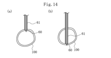
逆血検出部35は、内針60と外筒61との間に流入する逆血に加えて、内針60の基端側に流入する逆血を検出できるように構成されていてもよい。この場合、逆血検出部35は、外筒61と内針60またはこれらと連通する管状体に、それぞれカメラ等のセンサを有する。
図14(a)に示すように、外筒61から突出する内針60のみが血管100内に進入し、外筒61は血管100内に到達していない状態では、内針60の基端側に逆血が流入し、内針60と外筒61との間には逆血は流入しない。このため、逆血検出部35でこの状態を検出した場合、穿刺デバイス41が血管100に到達する直前の状態であると判別できる。
図14(b)に示すように、外筒61から突出する内針60のみが血管100を貫通し、外筒61は血管100内に位置している状態では、内針60と外筒61との間に逆血が流入し、内針60の基端側には逆血は流入しない。このため、逆血検出部35でこの状態を検出した場合、穿刺デバイス41が血管100を貫通する直前の状態であると判別できる。
このように、逆血検出部46が、内針60と外筒61との間に流入する逆血と、内針60の基端側に流入する逆血と、のいずれも検出できるようにすることで、穿刺デバイス41の位置検出の精度をより高くすることができる。
次に、血管穿刺装置10を用いた穿刺の第4変形例を説明する。本例において、穿刺パラメータを決定するまでのフロー(S1-1~S1-3)は、図5と同じであるため、説明は省略する。本例において、穿刺デバイス41は、内針60と外筒61とを有する。
図15において、制御部30は、穿刺パラメータを決定したら、撮像部22で取得した断面画像に基づき穿刺デバイス41の挿入深さに対する想定逆血量の相関を算出する(S5-4)。ここでは、穿刺デバイス41を血管100に対して挿入し、血管100に到達して貫通するまでの範囲について、相関が算出される。すなわち、第1の逆血についての想定逆血量が算出される。
次に、制御部30は、穿刺デバイス41の穿刺を開始する(S5-5)。制御部30は、穿刺を開始したら、逆血検出部35で検出された逆血の状態が、算出された相関に合致するか否かを判別する(S5-6)。逆血の状態が相関に合致する場合、穿刺デバイス41の挿入が継続される(S5-10)。逆血の状態が相関に合致しない場合、制御部30は、撮像部22で断面画像を取得し(S5-7)、取得した断面画像に基づき、内針60と血管100との位置関係が正常であるか否かを判別する(S5-8)。内針60と血管100との位置関係が正常ではない場合、制御部30は穿刺デバイス41の挿入を中止し、通知部23においてその旨を通知する(S5-9)。内針60と血管100との位置関係が正常である場合、制御部30は、S5-6からのフローを繰り返す。
制御部30は、穿刺デバイス41の挿入を継続している間、逆血検出部35が第1の逆血を検出するか否かを判別する(S5-11)。逆血検出部35で逆血が検出されない場合、制御部30は、先に説明したS5-7~S5-9のフローを実行する。S5-11で逆血が検出された場合、制御部30は、穿刺デバイス41の挿入を継続する(S5-12)。S5-12以降のフローは、図13のS4-11以降のフローと同じであるので、説明を省略する。
このように、内針60と外筒61とを有する穿刺デバイス41の挿入時に、挿入深さに対する想定逆血量の相関に合致するか判別することで、穿刺デバイス41の穿刺位置をより正確に把握することができ、穿刺の精度を高くすることができる。
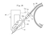
穿刺デバイス41には、前述のようにガイドワイヤ80が挿入される。ガイドワイヤ80は、術者が手動で挿入してもよいが、ガイドワイヤ駆動装置70によって自動的に挿入してもよい。図16に示すように、ガイドワイヤ駆動装置70は、ガイドワイヤ80を保持するホルダチューブ81の端部が保持されて、ガイドワイヤ80が挿入されるガイドワイヤ挿入部72と、挿入されたガイドワイヤ80を移動させるガイドワイヤ駆動部71と、穿刺デバイス41のハブ62が有する挿入部62aに連結される連結部73と、を有している。ガイドワイヤ駆動部71は、ガイドワイヤ80を挟む2つのローラー部71aを有しており、ガイドワイヤ80を長軸方向両側に移動させることができる。
ガイドワイヤ駆動装置70は、穿刺駆動部21によって穿刺デバイス41が血管に穿刺された後、ハブ62に連結される。ガイドワイヤ駆動装置70のハブ62に対する連結は、術者が行うが、ガイドワイヤ駆動装置70を移動させてハブ62に連結する連結装置をさらに設けてもよい。これにより、ガイドワイヤ駆動装置70を穿刺デバイス41に対し自動的に連結することができる。
このように、ガイドワイヤ駆動部71を有するガイドワイヤ駆動装置70を設けることで、穿刺後の手技を自動化することができる。
穿刺駆動部21は、穿刺デバイス41を駆動して穿刺できればよく、本実施形態の穿刺駆動部21の構成には限られない。図17に示すように、血管穿刺装置10は、穿刺デバイス41を三次元的に移動させることのできるロボットアームからなる穿刺駆動部91と、プローブ本体20とを有している。穿刺駆動部91は、図示しないセンサに基づく制御により、穿刺デバイス41を任意の位置から任意の角度で穿刺することができる。
基台部90に腕Hを挿通し、固定部92により固定したら、プローブ本体20で断面画像を取得し、断面画像から制御部30が穿刺タイミングと穿刺パラメータを決定する。穿刺駆動部91は、決定された穿刺の可否と穿刺の位置または方向と穿刺パラメータに従って腕Hに穿刺デバイス41を穿刺し、逆血を検出して穿刺が制御される。
以上のように、本実施形態に係る(1)血管穿刺装置10は、穿刺デバイス41を用いて生体に穿刺する血管穿刺装置10であって、穿刺デバイス41を生体に穿刺する穿刺駆動部21と、穿刺デバイス41に血管から流入する逆血を検出する逆血検出部35と、逆血検出部35で検出した逆血の情報に基づき、穿刺駆動部21を駆動して穿刺デバイス41の位置を制御する制御部30と、を有する。このように構成した血管穿刺装置10は、穿刺デバイス41の血管への穿刺に伴い発生する逆血の情報に基づき、穿刺デバイス41の位置を制御するので、穿刺デバイス41の血管への穿刺状態を正確に把握した上で位置制御できるため、精度よく穿刺を実行することができる。
(2)上記(1)の血管穿刺装置10において、穿刺デバイス41は内針60で構成され、制御部30は、穿刺駆動部21が穿刺デバイス41を挿入している際に、逆血検出部35が内針60の基端側に血管から流入する逆血を検出したら、穿刺デバイス41の挿入を停止するようにしてもよい。これにより、血管穿刺装置10は、逆血の検出により穿刺デバイス41が血管に進入したことを確認できるので、血管への穿刺を高精度に判別できる。
(3)上記(1)の血管穿刺装置10において、人体の断面画像を取得する撮像部22を備えたプローブ本体20をさらに有し、穿刺デバイス41は内針60で構成され、制御部30は、撮像部22で取得した断面画像に基づき穿刺デバイス41の想定挿入深さを算出し、穿刺駆動部21が穿刺デバイス41を挿入している際に、逆血検出部35が内針60の基端側に血管から流入する逆血を検出したら、穿刺デバイス41の挿入を継続し、穿刺デバイス41の挿入深さが想定算出深さに到達したら、撮像部22で断面画像を取得し、当該取得した断面画像に基づき、内針60と血管との位置関係が正常であるか否かを判別し、内針60と血管との位置関係が正常である場合には、穿刺デバイス41の挿入を停止し、内針60と血管との位置関係が正常である場合には、一定の中止処理を行うようにしてもよい。これにより、血管穿刺装置10は、穿刺デバイス41が血管壁を貫通した直後の状態よりも血管のより奥側まで穿刺デバイス41を挿入できるので、確実な穿刺を行うことができる。
(4)上記(1)の血管穿刺装置10において、人体の断面画像を取得する撮像部22を備えたプローブ本体20をさらに有し、穿刺デバイス41は内針60で構成され、制御部30は、撮像部22で取得した断面画像に基づき穿刺デバイス41の想定挿入深さを算出し、穿刺駆動部21が穿刺デバイス41を挿入している際に、逆血検出部35が内針60の基端側に血管から流入する逆血を検出すると共に、穿刺デバイス41の挿入深さが想定算出深さに到達したら、穿刺デバイス41の挿入を停止するようにしてもよい。これにより、血管穿刺装置10は、穿刺デバイス41が血管壁を貫通した直後の状態よりも血管のより奥側まで穿刺デバイス41を挿入できるので、確実な穿刺を行うことができる。
(5)上記(1)の血管穿刺装置10において、人体の断面画像を取得する撮像部22を備えたプローブ本体20をさらに有し、穿刺デバイス41は内針60で構成され、制御部30は、撮像部22で取得した断面画像に基づき穿刺デバイス41の挿入深さに対する想定逆血量の相関を算出し、穿刺駆動部21が穿刺デバイス41を挿入している際に、逆血検出部35で検出された逆血の状態が相関に合致するか否かを判別し、逆血の状態が相関に合致する場合は、穿刺デバイス41の挿入を継続し、逆血の状態が相関に合致しない場合は、一定の中止処理を行うようにしてもよい。これにより、血管穿刺装置10は、内針60の穿刺位置をより正確に把握することができ、穿刺の精度を高くすることができる。
(6)上記(1)の血管穿刺装置10において、穿刺デバイス41は、内針60と、該内針60を覆う外筒61と、を有し、内針60は、先端部が外筒61の先端から突出するとともに、穿刺駆動部21により外筒61から抜去可能であり、制御部30は、穿刺駆動部21が穿刺デバイス41を挿入している際に、逆血検出部35が内針60と外筒61との間に血管から流入する第1の逆血を検出したら、穿刺デバイス41の挿入を継続し、穿刺駆動部21が第1の逆血の検出後に穿刺デバイス41を挿入している際に、逆血検出部35が第1の逆血の停止を検出したら、穿刺デバイス41の挿入を停止し、穿刺デバイス41の挿入を停止したら、内針60を外筒61から抜去し、内針60を外筒61から抜去したら、外筒61を基端側に移動させ、穿刺駆動部21が外筒61を基端側に移動させている際に、逆血検出部35が外筒61の基端側に血管から流入する第2の逆血を検出したら、外筒61の移動を停止するようにしてもよい。これにより、血管穿刺装置10は、内針60の外側に外筒61を有する穿刺デバイス41において、血管を一旦貫通させ、内針60を抜去した上で外筒61のみ血管内に配置する穿刺を、逆血を検出しながら行うことができる。
(7)上記(1)の血管穿刺装置10において、穿刺デバイス41は、内針60と、該内針60を覆う外筒61と、を有し、内針60は、先端部が外筒61の先端から突出するとともに、穿刺駆動部21により外筒61から抜去可能であり、制御部30は、穿刺駆動部21が穿刺デバイス41を挿入している際に、逆血検出部35が内針60と外筒61との間に血管から流入する第1の逆血を検出した後、逆血検出部35が第1の逆血の停止を検出したら、穿刺デバイス41の挿入を停止し、穿刺駆動部21が外筒61を基端側に移動させている際に、逆血検出部35が外筒61の基端側に血管から流入する第2の逆血を検出したら、外筒61の移動を停止するようにしてもよい。これにより、血管穿刺装置10は、内針60の外側に外筒61を有する穿刺デバイス41において、血管を一旦貫通させ、内針60を抜去した上で外筒61のみ血管内に配置する穿刺を、逆血を検出しながら行うことができる。
(8)上記(1)~(7)のいずれかの血管穿刺装置10において、制御部30により制御される通知部23をさらに有し、制御部30は、逆血検出部35による逆血の情報から穿刺デバイス41の先端が血管内に位置していると判断したら、通知部23に通知させるようにしてもよい。これにより、術者は、穿刺後の手技を円滑に行うことができる。
(9)上記(1)~(8)のいずれかの血管穿刺装置10において、穿刺デバイス41にガイドワイヤ80を挿入するガイドワイヤ駆動部71をさらに有し、制御部30は、逆血検出部35による逆血の情報から穿刺デバイス41の先端が血管内に位置していると判断したら、ガイドワイヤ駆動部71によりガイドワイヤ80を血管内に挿入させるようにしてもよい。これにより、血管穿刺装置10は、穿刺デバイス41穿刺後に行われるガイドワイヤ80の挿入を自動化できる。
なお、本発明は、上述した実施形態のみに限定されるものではなく、本発明の技術的思想内において当業者により種々変更が可能である。例えば、本実施形態において取得した断面画像を表示するモニタは図示されていないが、血管穿刺装置10をモニタに接続して、断面画像を目視できるようにしてもよい。
血管穿刺装置10は、穿刺駆動部21と逆血検出部35および制御部30がそれぞれワイヤレスで接続され、情報を送受信できるように構成されていてもよい。
なお、本出願は、2022年9月26日に出願された日本特許出願2022-152985号に基づいており、それらの開示内容は、参照され、全体として、組み入れられている。
10 血管穿刺装置
20 プローブ本体
21 穿刺駆動部
21a 固定部
22 撮像部
23 通知部
30 制御部
32 送信部
34 受信部
35 逆血検出部
40 本体部
41 穿刺デバイス
60 内針
61 外筒
62 ハブ
62a 挿入部
70 ガイドワイヤ駆動装置
71 ガイドワイヤ駆動部
72 ガイドワイヤ挿入部
73 連結部
80 ガイドワイヤ
81 ホルダチューブ
100 血管
110 重心位置
H 腕
20 プローブ本体
21 穿刺駆動部
21a 固定部
22 撮像部
23 通知部
30 制御部
32 送信部
34 受信部
35 逆血検出部
40 本体部
41 穿刺デバイス
60 内針
61 外筒
62 ハブ
62a 挿入部
70 ガイドワイヤ駆動装置
71 ガイドワイヤ駆動部
72 ガイドワイヤ挿入部
73 連結部
80 ガイドワイヤ
81 ホルダチューブ
100 血管
110 重心位置
H 腕
Claims (9)
- 穿刺デバイスを用いて生体に穿刺する血管穿刺装置であって、
前記穿刺デバイスを生体に穿刺する穿刺駆動部と、
前記穿刺デバイスに血管から流入する逆血を検出する逆血検出部と、
前記逆血検出部で検出した逆血の情報に基づき、前記穿刺駆動部を駆動して前記穿刺デバイスの位置を制御する制御部と、を有する血管穿刺装置。 - 前記穿刺デバイスは内針で構成され、
前記制御部は、前記穿刺駆動部が前記穿刺デバイスを挿入している際に、前記逆血検出部が前記内針の基端側に血管から流入する逆血を検出したら、前記穿刺デバイスの挿入を停止する請求項1に記載の血管穿刺装置。 - 人体の断面画像を取得する撮像部を備えたプローブ本体をさらに有し、
前記穿刺デバイスは内針で構成され、
前記制御部は、
前記撮像部で取得した断面画像に基づき前記穿刺デバイスの想定挿入深さを算出し、
前記穿刺駆動部が前記穿刺デバイスを挿入している際に、前記逆血検出部が前記内針の基端側に血管から流入する逆血を検出したら、前記穿刺デバイスの挿入を継続し、
前記穿刺デバイスの挿入深さが前記想定算出深さに到達したら、前記撮像部で断面画像を取得し、当該取得した断面画像に基づき、前記内針と血管との位置関係が正常であるか否かを判別し、
前記内針と血管との位置関係が正常である場合には、前記穿刺デバイスの挿入を停止し、前記内針と血管との位置関係が正常である場合には、一定の中止処理を行う請求項1に記載の血管穿刺装置。 - 人体の断面画像を取得する撮像部を備えたプローブ本体をさらに有し、
前記穿刺デバイスは内針で構成され、
前記制御部は、
前記撮像部で取得した断面画像に基づき前記穿刺デバイスの想定挿入深さを算出し、
前記穿刺駆動部が前記穿刺デバイスを挿入している際に、前記逆血検出部が前記内針の基端側に血管から流入する逆血を検出すると共に、前記穿刺デバイスの挿入深さが前記想定算出深さに到達したら、前記穿刺デバイスの挿入を停止する請求項1に記載の血管穿刺装置。 - 人体の断面画像を取得する撮像部を備えたプローブ本体をさらに有し、
前記穿刺デバイスは内針で構成され、
前記制御部は、
前記撮像部で取得した断面画像に基づき前記穿刺デバイスの挿入深さに対する想定逆血量の相関を算出し、
前記穿刺駆動部が前記穿刺デバイスを挿入している際に、前記逆血検出部で検出された逆血の状態が前記相関に合致するか否かを判別し、前記逆血の状態が前記相関に合致する場合は、前記穿刺デバイスの挿入を継続し、前記逆血の状態が前記相関に合致しない場合は、一定の中止処理を行う請求項1に記載の血管穿刺装置。 - 前記穿刺デバイスは、内針と、該内針を覆う外筒と、を有し、前記内針は、先端部が前記外筒の先端から突出するとともに、前記穿刺駆動部により前記外筒から抜去可能であり、
前記制御部は、
前記穿刺駆動部が前記穿刺デバイスを挿入している際に、前記逆血検出部が前記内針と前記外筒との間に血管から流入する第1の逆血を検出したら、前記穿刺デバイスの挿入を継続し、
前記穿刺駆動部が前記第1の逆血の検出後に前記穿刺デバイスを挿入している際に、前記逆血検出部が前記第1の逆血の停止を検出したら、前記穿刺デバイスの挿入を停止し、
前記穿刺デバイスの挿入を停止したら、前記内針を前記外筒から抜去し、
前記内針を前記外筒から抜去したら、前記外筒を基端側に移動させ、
前記穿刺駆動部が前記外筒を基端側に移動させている際に、前記逆血検出部が前記外筒の基端側に血管から流入する第2の逆血を検出したら、前記外筒の移動を停止する請求項1に記載の血管穿刺装置。 - 前記穿刺デバイスは、内針と、該内針を覆う外筒と、を有し、前記内針は、先端部が前記外筒の先端から突出するとともに、前記穿刺駆動部により前記外筒から抜去可能であり、
前記制御部は、
前記穿刺駆動部が前記穿刺デバイスを挿入している際に、前記逆血検出部が前記内針と前記外筒との間に血管から流入する第1の逆血を検出した後、前記逆血検出部が前記第1の逆血の停止を検出したら、前記穿刺デバイスの挿入を停止し、
前記穿刺駆動部が前記外筒を基端側に移動させている際に、前記逆血検出部が前記外筒の基端側に血管から流入する第2の逆血を検出したら、前記外筒の移動を停止する請求項1に記載の血管穿刺装置。 - 前記制御部により制御される通知部をさらに有し、
前記制御部は、前記逆血検出部による逆血の情報から前記穿刺デバイスの先端が血管内に位置していると判断したら、前記通知部に通知させる請求項1~7のいずれか1項に記載の血管穿刺装置。 - 前記穿刺デバイスにガイドワイヤを挿入するガイドワイヤ駆動部をさらに有し、
前記制御部は、前記逆血検出部による逆血の情報から前記穿刺デバイスの先端が血管内に位置していると判断したら、前記ガイドワイヤ駆動部により前記ガイドワイヤを血管内に挿入させる請求項1~6のいずれか1項に記載の血管穿刺装置。
Priority Applications (2)
| Application Number | Priority Date | Filing Date | Title |
|---|---|---|---|
| JP2024549335A JPWO2024070976A1 (ja) | 2022-09-26 | 2023-09-22 | |
| US19/090,233 US20250221736A1 (en) | 2022-09-26 | 2025-03-25 | Vascular puncture apparatus |
Applications Claiming Priority (2)
| Application Number | Priority Date | Filing Date | Title |
|---|---|---|---|
| JP2022-152985 | 2022-09-26 | ||
| JP2022152985 | 2022-09-26 |
Related Child Applications (1)
| Application Number | Title | Priority Date | Filing Date |
|---|---|---|---|
| US19/090,233 Continuation US20250221736A1 (en) | 2022-09-26 | 2025-03-25 | Vascular puncture apparatus |
Publications (1)
| Publication Number | Publication Date |
|---|---|
| WO2024070976A1 true WO2024070976A1 (ja) | 2024-04-04 |
Family
ID=90477762
Family Applications (1)
| Application Number | Title | Priority Date | Filing Date |
|---|---|---|---|
| PCT/JP2023/034583 Ceased WO2024070976A1 (ja) | 2022-09-26 | 2023-09-22 | 血管穿刺装置 |
Country Status (3)
| Country | Link |
|---|---|
| US (1) | US20250221736A1 (ja) |
| JP (1) | JPWO2024070976A1 (ja) |
| WO (1) | WO2024070976A1 (ja) |
Citations (4)
| Publication number | Priority date | Publication date | Assignee | Title |
|---|---|---|---|---|
| CN104188712A (zh) * | 2014-08-07 | 2014-12-10 | 王燕青 | 一种自动式动脉穿刺器及使用方法 |
| WO2019235518A1 (ja) * | 2018-06-06 | 2019-12-12 | テルモ株式会社 | 穿刺システム |
| WO2022153727A1 (ja) * | 2021-01-18 | 2022-07-21 | テルモ株式会社 | 超音波プローブ |
| WO2023002934A1 (ja) * | 2021-07-21 | 2023-01-26 | テルモ株式会社 | 血管穿刺装置および血管穿刺システム |
-
2023
- 2023-09-22 WO PCT/JP2023/034583 patent/WO2024070976A1/ja not_active Ceased
- 2023-09-22 JP JP2024549335A patent/JPWO2024070976A1/ja active Pending
-
2025
- 2025-03-25 US US19/090,233 patent/US20250221736A1/en active Pending
Patent Citations (4)
| Publication number | Priority date | Publication date | Assignee | Title |
|---|---|---|---|---|
| CN104188712A (zh) * | 2014-08-07 | 2014-12-10 | 王燕青 | 一种自动式动脉穿刺器及使用方法 |
| WO2019235518A1 (ja) * | 2018-06-06 | 2019-12-12 | テルモ株式会社 | 穿刺システム |
| WO2022153727A1 (ja) * | 2021-01-18 | 2022-07-21 | テルモ株式会社 | 超音波プローブ |
| WO2023002934A1 (ja) * | 2021-07-21 | 2023-01-26 | テルモ株式会社 | 血管穿刺装置および血管穿刺システム |
Non-Patent Citations (4)
| Title |
|---|
| "Practical guide for safe central venous catheterization and management 2017", JOURNAL OF ANESTHESIA, SPRINGER SINGAPORE, SINGAPORE, vol. 34, no. 2, 30 November 2019 (2019-11-30), Singapore, pages 167 - 186, XP037121151, ISSN: 0913-8668, DOI: 10.1007/s00540-019-02702-9 * |
| ASAI, YASUFUMI: "Arterial puncture and catheterization", SURGICAL THERAPY - GEKA CHIRYO, NAGAI SHOTEN CO. LTD., JP, vol. 74, no. 5, 1 May 1996 (1996-05-01), JP , pages 597 - 600, XP009554357, ISSN: 0433-2644 * |
| NAGAHAMA, SHOTARO: "Summary of important points for securing and placing blood vessels", JOURNAL OF VETERINARY ANESTHESIOLOGY, vol. 44, no. Suppl.2, 20 December 2013 (2013-12-20), pages 80, XP009554065, ISSN: 0916-5908 * |
| SHOTARO SUMITANI: "An Algorithm for Peripheral-Short Catheter Insertion in Vascular Access", JAPANESE JOURNAL OF NURSING ART AND SCIENCE, vol. 15, no. 1, 1 January 2016 (2016-01-01), pages 81 - 86, XP093156785, DOI: 10.18892/jsnas.15.1_81 * |
Also Published As
| Publication number | Publication date |
|---|---|
| US20250221736A1 (en) | 2025-07-10 |
| JPWO2024070976A1 (ja) | 2024-04-04 |
Similar Documents
| Publication | Publication Date | Title |
|---|---|---|
| US20250104238A1 (en) | Ultrasound System with Pressure and Flow Determination Capability | |
| JP7182240B2 (ja) | 穿刺システム及び穿刺制御装置 | |
| CN108836440B (zh) | 一种穿刺辅助机器人的控制决策方法与系统 | |
| US20240139435A1 (en) | Vascular puncture assistance device | |
| US20080221519A1 (en) | System for Guiding a Probe Over the Surface of the Skin of a Patient or an Animal | |
| KR101948539B1 (ko) | 초음파 탐촉 기반의 주사기 정렬 유도장치 | |
| JP2014150928A (ja) | 超音波診断装置 | |
| WO2023002933A1 (ja) | 血管穿刺装置および血管穿刺システム | |
| CN104856725A (zh) | 血压测量装置 | |
| US12544035B2 (en) | Ultrasound probe | |
| WO2024070978A1 (ja) | 血管穿刺装置および血管判定装置 | |
| WO2022153725A1 (ja) | 血管位置表示器 | |
| CN110464304A (zh) | 一种采血方法及设备 | |
| JP4365841B2 (ja) | 超音波診断装置 | |
| JP2005066310A (ja) | 静脈注射装置 | |
| KR101783207B1 (ko) | 흡입 시술 지원 시스템 및 방법 | |
| JP2016116747A (ja) | 血管穿刺用補助装置、及びこれを用いた血管穿刺装置 | |
| US20250221736A1 (en) | Vascular puncture apparatus | |
| WO2024070977A1 (ja) | 逆血抑制装置 | |
| JP2004313271A (ja) | 超音波診断装置 | |
| JP2024036700A (ja) | 血管位置表示器 | |
| WO2023002934A1 (ja) | 血管穿刺装置および血管穿刺システム | |
| JP2023016128A (ja) | 血管穿刺支援装置 | |
| US6899678B2 (en) | Puncture difficulty evaluating device | |
| JP3920867B2 (ja) | 超音波診断装置 |
Legal Events
| Date | Code | Title | Description |
|---|---|---|---|
| 121 | Ep: the epo has been informed by wipo that ep was designated in this application |
Ref document number: 23872201 Country of ref document: EP Kind code of ref document: A1 |
|
| WWE | Wipo information: entry into national phase |
Ref document number: 2024549335 Country of ref document: JP |
|
| NENP | Non-entry into the national phase |
Ref country code: DE |
|
| 122 | Ep: pct application non-entry in european phase |
Ref document number: 23872201 Country of ref document: EP Kind code of ref document: A1 |