WO2024070873A1 - 切断装置用ユニット、切断装置及びシート断片の製造方法 - Google Patents
切断装置用ユニット、切断装置及びシート断片の製造方法 Download PDFInfo
- Publication number
- WO2024070873A1 WO2024070873A1 PCT/JP2023/034208 JP2023034208W WO2024070873A1 WO 2024070873 A1 WO2024070873 A1 WO 2024070873A1 JP 2023034208 W JP2023034208 W JP 2023034208W WO 2024070873 A1 WO2024070873 A1 WO 2024070873A1
- Authority
- WO
- WIPO (PCT)
- Prior art keywords
- cutting blade
- unit
- cutting device
- holder
- light
- Prior art date
- Legal status (The legal status is an assumption and is not a legal conclusion. Google has not performed a legal analysis and makes no representation as to the accuracy of the status listed.)
- Ceased
Links
Images


Classifications
-
- B—PERFORMING OPERATIONS; TRANSPORTING
- B65—CONVEYING; PACKING; STORING; HANDLING THIN OR FILAMENTARY MATERIAL
- B65H—HANDLING THIN OR FILAMENTARY MATERIAL, e.g. SHEETS, WEBS, CABLES
- B65H35/00—Delivering articles from cutting or line-perforating machines; Article or web delivery apparatus incorporating cutting or line-perforating devices, e.g. adhesive tape dispensers
- B65H35/0006—Article or web delivery apparatus incorporating cutting or line-perforating devices
- B65H35/0073—Details
- B65H35/008—Arrangements or adaptations of cutting devices
-
- B—PERFORMING OPERATIONS; TRANSPORTING
- B26—HAND CUTTING TOOLS; CUTTING; SEVERING
- B26D—CUTTING; DETAILS COMMON TO MACHINES FOR PERFORATING, PUNCHING, CUTTING-OUT, STAMPING-OUT OR SEVERING
- B26D1/00—Cutting through work characterised by the nature or movement of the cutting member or particular materials not otherwise provided for; Apparatus or machines therefor; Cutting members therefor
- B26D1/0006—Cutting members therefor
-
- B—PERFORMING OPERATIONS; TRANSPORTING
- B26—HAND CUTTING TOOLS; CUTTING; SEVERING
- B26D—CUTTING; DETAILS COMMON TO MACHINES FOR PERFORATING, PUNCHING, CUTTING-OUT, STAMPING-OUT OR SEVERING
- B26D1/00—Cutting through work characterised by the nature or movement of the cutting member or particular materials not otherwise provided for; Apparatus or machines therefor; Cutting members therefor
- B26D1/01—Cutting through work characterised by the nature or movement of the cutting member or particular materials not otherwise provided for; Apparatus or machines therefor; Cutting members therefor involving a cutting member which does not travel with the work
- B26D1/12—Cutting through work characterised by the nature or movement of the cutting member or particular materials not otherwise provided for; Apparatus or machines therefor; Cutting members therefor involving a cutting member which does not travel with the work having a cutting member moving about an axis
- B26D1/14—Cutting through work characterised by the nature or movement of the cutting member or particular materials not otherwise provided for; Apparatus or machines therefor; Cutting members therefor involving a cutting member which does not travel with the work having a cutting member moving about an axis with a circular cutting member, e.g. disc cutter
- B26D1/24—Cutting through work characterised by the nature or movement of the cutting member or particular materials not otherwise provided for; Apparatus or machines therefor; Cutting members therefor involving a cutting member which does not travel with the work having a cutting member moving about an axis with a circular cutting member, e.g. disc cutter coacting with another disc cutter
- B26D1/245—Cutting through work characterised by the nature or movement of the cutting member or particular materials not otherwise provided for; Apparatus or machines therefor; Cutting members therefor involving a cutting member which does not travel with the work having a cutting member moving about an axis with a circular cutting member, e.g. disc cutter coacting with another disc cutter for thin material, e.g. for sheets, strips or the like
-
- B—PERFORMING OPERATIONS; TRANSPORTING
- B26—HAND CUTTING TOOLS; CUTTING; SEVERING
- B26D—CUTTING; DETAILS COMMON TO MACHINES FOR PERFORATING, PUNCHING, CUTTING-OUT, STAMPING-OUT OR SEVERING
- B26D1/00—Cutting through work characterised by the nature or movement of the cutting member or particular materials not otherwise provided for; Apparatus or machines therefor; Cutting members therefor
- B26D1/01—Cutting through work characterised by the nature or movement of the cutting member or particular materials not otherwise provided for; Apparatus or machines therefor; Cutting members therefor involving a cutting member which does not travel with the work
- B26D1/12—Cutting through work characterised by the nature or movement of the cutting member or particular materials not otherwise provided for; Apparatus or machines therefor; Cutting members therefor involving a cutting member which does not travel with the work having a cutting member moving about an axis
- B26D1/25—Cutting through work characterised by the nature or movement of the cutting member or particular materials not otherwise provided for; Apparatus or machines therefor; Cutting members therefor involving a cutting member which does not travel with the work having a cutting member moving about an axis with a non-circular cutting member
- B26D1/26—Cutting through work characterised by the nature or movement of the cutting member or particular materials not otherwise provided for; Apparatus or machines therefor; Cutting members therefor involving a cutting member which does not travel with the work having a cutting member moving about an axis with a non-circular cutting member moving about an axis substantially perpendicular to the line of cut
- B26D1/265—Cutting through work characterised by the nature or movement of the cutting member or particular materials not otherwise provided for; Apparatus or machines therefor; Cutting members therefor involving a cutting member which does not travel with the work having a cutting member moving about an axis with a non-circular cutting member moving about an axis substantially perpendicular to the line of cut for thin material, e.g. for sheets, strips or the like
-
- B—PERFORMING OPERATIONS; TRANSPORTING
- B26—HAND CUTTING TOOLS; CUTTING; SEVERING
- B26D—CUTTING; DETAILS COMMON TO MACHINES FOR PERFORATING, PUNCHING, CUTTING-OUT, STAMPING-OUT OR SEVERING
- B26D5/00—Arrangements for operating and controlling machines or devices for cutting, cutting-out, stamping-out, punching, perforating, or severing by means other than cutting
- B26D5/02—Means for moving the cutting member into its operative position for cutting
- B26D5/06—Means for moving the cutting member into its operative position for cutting by electrical means
-
- B—PERFORMING OPERATIONS; TRANSPORTING
- B26—HAND CUTTING TOOLS; CUTTING; SEVERING
- B26D—CUTTING; DETAILS COMMON TO MACHINES FOR PERFORATING, PUNCHING, CUTTING-OUT, STAMPING-OUT OR SEVERING
- B26D7/00—Details of apparatus for cutting, cutting-out, stamping-out, punching, perforating, or severing by means other than cutting
- B26D7/26—Means for mounting or adjusting the cutting member; Means for adjusting the stroke of the cutting member
- B26D7/2614—Means for mounting the cutting member
- B26D7/2621—Means for mounting the cutting member for circular cutters
-
- B—PERFORMING OPERATIONS; TRANSPORTING
- B26—HAND CUTTING TOOLS; CUTTING; SEVERING
- B26D—CUTTING; DETAILS COMMON TO MACHINES FOR PERFORATING, PUNCHING, CUTTING-OUT, STAMPING-OUT OR SEVERING
- B26D7/00—Details of apparatus for cutting, cutting-out, stamping-out, punching, perforating, or severing by means other than cutting
- B26D7/26—Means for mounting or adjusting the cutting member; Means for adjusting the stroke of the cutting member
- B26D7/2628—Means for adjusting the position of the cutting member
- B26D7/265—Journals, bearings or supports for positioning rollers or cylinders relatively to each other
-
- B—PERFORMING OPERATIONS; TRANSPORTING
- B65—CONVEYING; PACKING; STORING; HANDLING THIN OR FILAMENTARY MATERIAL
- B65H—HANDLING THIN OR FILAMENTARY MATERIAL, e.g. SHEETS, WEBS, CABLES
- B65H35/00—Delivering articles from cutting or line-perforating machines; Article or web delivery apparatus incorporating cutting or line-perforating devices, e.g. adhesive tape dispensers
- B65H35/0006—Article or web delivery apparatus incorporating cutting or line-perforating devices
- B65H35/0073—Details
- B65H35/008—Arrangements or adaptations of cutting devices
- B65H35/0086—Arrangements or adaptations of cutting devices using movable cutting elements
-
- B—PERFORMING OPERATIONS; TRANSPORTING
- B65—CONVEYING; PACKING; STORING; HANDLING THIN OR FILAMENTARY MATERIAL
- B65H—HANDLING THIN OR FILAMENTARY MATERIAL, e.g. SHEETS, WEBS, CABLES
- B65H35/00—Delivering articles from cutting or line-perforating machines; Article or web delivery apparatus incorporating cutting or line-perforating devices, e.g. adhesive tape dispensers
- B65H35/02—Delivering articles from cutting or line-perforating machines; Article or web delivery apparatus incorporating cutting or line-perforating devices, e.g. adhesive tape dispensers from or with longitudinal slitters or perforators
-
- B—PERFORMING OPERATIONS; TRANSPORTING
- B26—HAND CUTTING TOOLS; CUTTING; SEVERING
- B26D—CUTTING; DETAILS COMMON TO MACHINES FOR PERFORATING, PUNCHING, CUTTING-OUT, STAMPING-OUT OR SEVERING
- B26D1/00—Cutting through work characterised by the nature or movement of the cutting member or particular materials not otherwise provided for; Apparatus or machines therefor; Cutting members therefor
- B26D1/0006—Cutting members therefor
- B26D2001/002—Materials or surface treatments therefor, e.g. composite materials
Definitions
- the present disclosure relates to a unit used in a cutting device that cuts sheet-like members to a predetermined width, and to a cutting device and a method for manufacturing sheet fragments.
- sheet-like members include members such as metal foil, paper, and resin film.
- the slitter device described in Japanese Patent Laid-Open Publication No. 1-321197 (Patent Document 1) and Japanese Utility Model Laid-Open Publication No. 4-122488 (Patent Document 2) is known.
- the slitter device described in Patent Document 1 has multiple ring-shaped cutting blades and multiple lamps electrically connected to each of the multiple cutting blades.
- the slitter device described in Patent Document 2 also has multiple ring-shaped thin blades and multiple light-emitting elements electrically connected to each of the multiple thin blades. In both of the slitter devices described in Patent Documents 1 and 2, the contact state of the cutting blades (thin blades) is detected by using lamps (light-emitting elements).
- lamps are attached to the device body.
- the number and positions of the cutting blades may change in order to obtain cut pieces of the desired width. This can make it difficult to understand the correspondence between the lamps and the cutting blades.
- the non-limiting one-sided cutting device unit of the present disclosure comprises a base, a first shaft member attached to the base and extending along a first rotation axis, a cylindrical holder attached to the first shaft member, a first annular cutting blade member attached to the holder, a second shaft member attached to the base and extending along a second rotation axis parallel to the first rotation axis, a second cylindrical cutting blade member attached to the second shaft member, and a detection means for detecting contact between the first cutting blade member and the second cutting blade member.
- the second shaft member, the first cutting blade member, and the second cutting blade member are each electrically conductive
- the detection means includes a power source, a connection terminal attached to the holder, a light-emitting member attached to the holder, a first wiring electrically connecting the connection terminal and the power source, a second wiring electrically connecting the second shaft member and the power source, a third wiring electrically connecting the light-emitting member and the connection terminal, and a fourth wiring electrically connecting the light-emitting member and the first cutting blade member.
- FIG. 2 is a perspective view showing a non-limiting one-sided cutting device unit of the present disclosure.
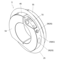
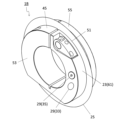
- 2 is a perspective view of a holder and a first cutting blade member in the cutting device unit shown in FIG. 1 .
- 3 is a view of the holder and the first cutting blade member shown in FIG. 2 viewed from a direction perpendicular to an outer circumferential surface of the holder.
- FIG. FIG. 4 is an exploded view of the holder shown in FIG. 3 . 4 is a plan view of the holder and the first cutting blade member shown in FIG. 3 as viewed from a V direction.
- FIG. 2 is a perspective view showing a holder in a non-limiting one-sided cutting device unit of the present disclosure.
- 9 is a cross-sectional view of a state in which a first cutting blade member is attached to the holder shown in FIG. 8, and corresponds to FIG. 7.
- FIG. FIG. 2 is a perspective view showing a holder and a first cutting blade member in a non-limiting one-sided cutting device unit of the present disclosure.
- 11 is a plan view of the holder and the first cutting blade member shown in FIG. 10, and corresponds to FIG. 5.
- FIG. 12 is a cross-sectional view taken along line XII-XII of FIG. 11.
- FIG. 2 is a schematic diagram showing a non-limiting cutting device (method for producing sheet fragments) of the present disclosure.
- a non-limiting one-sided cutting device unit 1 (hereinafter, sometimes referred to as "unit 1") of the present disclosure will be described in detail with reference to the drawings.
- the unit 1 may include any component member not shown in each of the drawings referred to.
- the dimensions of the components in each drawing do not faithfully represent the actual dimensions of the component members and the dimensional ratios of each component.
- the unit 1 may have a base 3, a first shaft member 5, and a second shaft member 7, as shown in a non-limiting example in FIG. 1.
- the first shaft member 5 may be attached to the base 3.
- the first shaft member 5 may be detachably attached to the base 3.
- the first shaft member 5 may extend along the first rotation axis O1.
- the first shaft member 5 is rotatable around the first rotation axis O1.
- the first shaft member 5 is not limited to a specific size.
- the length of the first shaft member 5 in the direction along the first rotation axis O1 may be set to approximately 300 to 4000 mm.
- the width (diameter) of the first shaft member 5 in the direction perpendicular to the first rotation axis O1 may be set to approximately 30 to 150 mm.
- the first shaft member 5 may have a circular cross section perpendicular to the first rotation axis O1.
- the second shaft member 7 may be attached to the base 3.
- the second shaft member 7 may be detachably attached to the base 3.
- the second shaft member 7 may also extend along the second rotation axis O2.
- the second shaft member 7 is rotatable around the second rotation axis O2.
- the second shaft member 7 may be located below the first shaft member 5.
- the second shaft member 7 can rotate in the opposite direction to the first shaft member 5.
- meshing gears are attached to the first shaft member 5 and the second shaft member 7, when the first shaft member 5 rotates, the second shaft member 7 can rotate in the opposite direction to the first shaft member 5 in accordance with the rotation of the first shaft member 5.
- the second rotation axis O2 may be parallel to the first rotation axis O1. Parallel does not have to be strictly parallel, but may mean allowing a tilt of about ⁇ 5°.
- the second rotation axis O2 may overlap with the first rotation axis O1 when the unit 1 is viewed in plan from the side of the first shaft member 5.
- the second shaft member 7 is not limited to a specific size.
- the length of the second shaft member 7 in the direction along the second rotation axis O2 may be set to approximately 300 to 4000 mm.
- the width (diameter) of the second shaft member 7 in the direction perpendicular to the second rotation axis O2 may be set to approximately 30 to 150 mm.
- the second shaft member 7 may have a circular cross section perpendicular to the second rotation axis O2.
- the base 3 may have a lower plate portion 9 and a pair of side wall portions 11 fixed to the lower plate portion 9 with their main surfaces facing each other.
- the lower plate portion 9 may have a rectangular upper surface 13.
- the pair of side wall portions 11 may be fixed to the lower plate portion 9 along the short sides of the upper surface 13.
- the first shaft member 5 and the second shaft member 7 may be positioned parallel to the upper surface 13 of the lower plate portion 9.
- the lower plate portion 9 is not limited to a particular size.
- the width of the lower plate portion 9 in the x-axis direction may be set to approximately 400 to 5000 mm.
- the width of the lower plate portion 9 in the y-axis direction may be set to approximately 100 to 500 mm.
- the width (thickness) of the lower plate portion 9 in the z-axis direction may be set to approximately 20 to 100 mm.
- the direction parallel to the first rotation axis O1 and the second rotation axis O2 may be the x-axis direction.
- the direction perpendicular to the x-axis direction and parallel to the upper surface 13 of the lower plate portion 9 may be the y-axis direction.
- the vertical direction in FIG. 1, which is perpendicular to the x-axis and y-axis directions, may be the z-axis direction.
- the pair of side wall portions 11 may each have a first support portion 15 and a second support portion 17 that are independent of each other.
- the first support portion 15 is capable of mounting the first shaft member 5.
- the unit 1 may have a pair of first bearing members 19 mounted on both ends of the first shaft member 5.
- the first bearing members 19 may be held by the first support portion 15, thereby mounting the first shaft member 5 to the first support portion 15. In these cases, it is easy to rotate the first shaft member 5 while stably holding it by the first support portion 15.
- the first bearing member 19 may be, for example, a ring-shaped bearing. This bearing may also be referred to as the first bearing.
- the first bearing is not limited to a specific size. For example, the outer diameter of the first bearing may be set to approximately 30 to 150 mm.
- the second support portion 17 may be located below the first support portion 15.
- the second support portion 17 is capable of mounting the second shaft member 7.
- the unit 1 may have a pair of second bearing members 21 mounted on both ends of the second shaft member 7.
- the second bearing members 21 may be held by the second support portion 17, thereby mounting the second shaft member 7 to the second support portion 17. In these cases, it is easy to rotate the second shaft member 7 while the second support portion 17 holds the second shaft member 7 stably.
- the second bearing member 21 may be, for example, a ring-shaped bearing. This bearing may also be referred to as the second bearing.
- the second bearing is not limited to a specific size. For example, the outer diameter of the second bearing may be set to about 30 to 150 mm.
- the pair of side walls 11 are not limited to a specific size.
- the width (thickness) of the side walls 11 in the x-axis direction may be set to about 10 to 60 mm.
- the width of the side walls 11 in the y-axis direction may be set to about 100 to 500 mm.
- the width of the side walls 11 in the z-axis direction may be set to about 200 to 800 mm.
- the base 3 may have any configuration that is strong enough to stably hold the first shaft member 5 and the second shaft member 7. Therefore, the base 3 is not limited to a configuration formed by a lower plate portion 9 and a pair of side walls 11.
- the base 3 may have a concave configuration in which the lower plate portion 9 and a pair of side walls 11 are integrally formed. Examples of materials for the base 3 include steel and stainless steel.
- the unit 1 may have a holder 23.
- the holder 23 may be cylindrical.
- the holder 23 may be attached to the first shaft member 5.
- the holder 23 may be detachably attached to the first shaft member 5.
- the holder 23 may function as a member that fixes the first cutting blade member 25, which will be described later, to the first shaft member 5.
- the unit 1 may have multiple holders 23. Adjacent holders 23 may be in contact with each other or may be separated from each other. The number of holders 23 may be 1 to 30.
- the unit 1 may have a first cutting blade member 25.
- the first cutting blade member 25 may be annular.
- the first cutting blade member 25 may be attached to the holder 23.
- the first cutting blade member 25 may be detachably attached to the holder 23.
- the unit 1 may have a plurality of first cutting blade members 25.
- the number of first cutting blade members 25 may be 1 to 30.
- the number of first cutting blade members 25 may be the same as the number of holders 23.
- the first cutting blade member 25 may also be a disk-shaped or dish-shaped member.
- the first cutting blade member 25 may also be called a circular blade.
- the first cutting blade member 25 can be fixed to the first shaft member 5 via the holder 23. Therefore, when the first shaft member 5 rotates, the first cutting blade member 25 can also rotate in accordance with the rotation of the first shaft member 5. Furthermore, when the unit 1 has a plurality of holders 23 and first cutting blade members 25, adjusting the spacing between adjacent holders 23 makes it possible to adjust the spacing between adjacent first cutting blade members 25 accordingly.
- the unit 1 may have a second cutting blade member 27.
- the second cutting blade member 27 may be cylindrical.
- the second cutting blade member 27 may be attached to the second shaft member 7.
- the second cutting blade member 27 may be detachably attached to the second shaft member 7. When the second cutting blade member 27 is attached to the second shaft member 7, the second cutting blade member 27 can also rotate in accordance with the rotation of the second shaft member 7.
- the unit 1 may have multiple second cutting blade members 27.
- the number of second cutting blade members 27 may be 1 to 30.
- the second cutting blade member 27 may be attached to the second shaft member 7 so that the side of the second cutting blade member 27 contacts the side of the first cutting blade member 25.
- a shear force may be generated between the first cutting blade member 25 and the second cutting blade member 27 due to the side of the first cutting blade member 25, which is relatively easily elastically deformed, coming into contact with the side of the second cutting blade member 27, which is relatively less easily elastically deformed.
- This shear force makes it possible to cut the sheet-like material. Therefore, it is possible to cut the relatively wide sheet-like material sent to the unit 1 with the first cutting blade member 25 and the second cutting blade member 27 into a relatively narrow sheet product (sheet fragment).
- the second shaft member 7, the first cutting blade member 25, and the second cutting blade member 27 may each be electrically conductive.
- these members may be made of a material that is electrically conductive. Examples of electrically conductive materials include copper, steel, stainless steel, and aluminum.
- the second shaft member 7, the first cutting blade member 25, and the second cutting blade member 27 may have a conductive surface.
- these members may have a configuration including an insulating base and a conductive coating film located on the base.
- Examples of the insulating substrate material include resin, ceramics, and diamond-like carbon (DLC).
- Examples of the resin include polyethylene, polypropylene , polystyrene, and polyvinyl chloride.
- Examples of the ceramic include alumina ( Al2O3 ), zirconia ( ZrO2 ), aluminum nitride (AlN), silicon carbide (SiC), and silicon nitride ( Si3N4 ).
- the material of the conductive coating film may be, for example, a Ti-based coating containing Ti.
- Ti-based coatings include TiN, TiC, TiCN, TiAlN, TiAlCN, and TiAlON.
- the conductive coating film may also be called a conductive film.
- the coating film may be positioned on the substrate by using a chemical vapor deposition (CVD) method or a physical vapor deposition (PVD) method.
- At least one of the second shaft member 7, the first cutting blade member 25, and the second cutting blade member 27 may be made of a conductive material, and the remaining members may be configured to have an insulating base and a conductive coating film located on the base.
- the unit 1 may have a detection means 29 that detects contact between the first cutting blade member 25 and the second cutting blade member 27.
- the detection means 29 may have a power source 31, a connection terminal 33, a light-emitting member 35, a first wiring 37, a second wiring 39, a third wiring 41, and a fourth wiring 43, as shown in a non-limiting example in Figures 1 to 7.
- connection terminal 33 may be attached to the holder 23.
- the light emitting member 35 may also be attached to the holder 23.
- the first wiring 37 may be electrically connected to the connection terminal 33 and the power source 31.
- the second wiring 39 may be electrically connected to the second shaft member 7 and the power source 31.
- the third wiring 41 may be electrically connected to the light emitting member 35 and the connection terminal 33.
- the fourth wiring 43 may be electrically connected to the light emitting member 35 and the first cutting blade member 25.
- the detection means 29 since the light-emitting member 35 is attached to the holder 23 instead of the base 3, it is easy to understand the correspondence between the light-emitting member 35 and the first cutting blade member 25 even if the position of the first cutting blade member 25 changes. Also, in the detection means 29, a circuit can be formed by the first wiring 37, the second wiring 39, the third wiring 41, and the fourth wiring 43. Therefore, the detection means can be introduced into existing cutting device units in which the first shaft member 5 and the second shaft member 7 are generally conductive, without making complex modifications.
- the base 3, the first shaft member 5, and the second shaft member 7 are generally made of conductive metals such as steel and stainless steel.
- a detection means for detecting the contact between the first cutting blade member 25 and the second cutting blade member 27 is attached to the unit 1
- both the first shaft member 5 and the second shaft member 7 are used as part of the electrical circuit in the detection means
- electrical short circuits between the base 3, the first shaft member 5, and the second shaft member 7 can become a problem. Therefore, an insulating coating is required for either the base 3, the first shaft member 5, or the second shaft member 7.
- the base 3, the first shaft member 5, and the second shaft member 7 are all large parts, it is not easy to apply an insulating coating, and there is a risk of requiring a large amount of modification costs.
- the first shaft member 5 is not used as part of the electrical circuit.
- the electrical circuit in the detection means 29 is formed by the connection terminal 33 attached to the holder 23, and the first wiring 37 electrically connected to the connection terminal 33 and the power source 31, etc.
- the first shaft member 5 is prevented from becoming part of the electrical circuit by applying an insulating coating to the portion of the holder 23 that comes into contact with the first shaft member 5, or by forming the holder 23 from an insulating material.
- the holder 23 is a small, lightweight, and inexpensive component compared to the first shaft member 5. Therefore, the detection means 29 can be introduced into existing cutting device units simply by replacing the holder 23, without the need for complex modifications that would require significant modification costs.
- the first wiring 37, the second wiring 39, the third wiring 41, and the fourth wiring 43 are components for electrically connecting the detection means 29 and the power source 31 to form a circuit. Therefore, the first wiring 37, the second wiring 39, the third wiring 41, and the fourth wiring 43 do not need to be "wiring" in the strict sense. For example, these wirings may be partially constituted by "terminals".
- Examples of the light-emitting members 35 include lamps and LEDs.
- the unit 1 may have multiple light-emitting members 35.
- the number of light-emitting members 35 may range from 1 to 30.
- the number of light-emitting members 35 may be the same as the number of holders 23.
- the holder 23 may be insulating, as described above. In this case, the holder 23 is less likely to be electrically shorted to the first shaft member 5. In addition, it is easier to form the third wiring 41 and the fourth wiring 43.
- the holder 23 may be made of an insulating material. Examples of insulating materials include the same materials as those exemplified for the insulating base described above.
- the holder 23 may have an insulating surface.
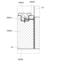
- the holder 23 may have a cylindrical main body 45, an inner peripheral surface 47 of the main body 45, and a coating film 49 located on the inner peripheral surface 47.
- the main body 45 of the holder 23 may be conductive, and the coating film 49 may be insulating.
- the body 45 of the holder 23 is conductive, the body 45 may be used as either the third wiring 41 or the fourth wiring 43, while taking care to avoid electrical short-circuiting between the third wiring 41 and the fourth wiring 43.
- the body 45 may be used as the fourth wiring 43 with the third wiring 41 covered with an insulating material embedded inside the body 45.
- the body 45 may be used as the third wiring 41 with the fourth wiring 43 covered with an insulating material embedded inside the body 45.
- the material of the conductive main body 45 may be, for example, the same materials as those exemplified for the second shaft member 7.
- the material of the insulating coating film 49 may be, for example, resin, ceramics, and DLC (Diamond-like Carbon).
- the insulating coating film 49 may be located on other surfaces of the main body 45 in addition to the inner circumferential surface 47.
- the insulating coating film 49 may also be referred to as an insulating film.
- the distance L1 between the connection terminal 33 and the light-emitting member 35 may be less than half the outer diameter D of the holder 23, as shown in a non-limiting example in FIG. 5. In this case, it is possible to shorten the length of the third wiring 41, which can contribute to reducing manufacturing costs and improving the rigidity of the holder 23.
- the distance L1 and the outer diameter D are not limited to a specific size.
- the distance L1 may be set to about 5 to 80 mm.
- the outer diameter D may be set to about 60 to 180 mm.
- the holder 23 may have a first main surface 51 and a second main surface 53, as shown in a non-limiting example in Figures 3 and 4.
- the second main surface 53 may be located opposite the first main surface 51.
- the first cutting blade member 25 may contact the first main surface 51.
- the main body 45 may have a first main surface 51 and a second main surface 53.
- the holder 23 may further have a lid body 55.
- the lid body 55 may function as a member that fixes the first cutting blade member 25 to the main body 45.
- the main body 45 may have a male thread 57 located on the first main surface 51, as in the non-limiting example shown in FIG. 4.
- the cover 55 may have a female thread 59 fixed to the male thread 57.
- the first cutting blade member 25 may be located between the first main surface 51 and the cover 55. In these cases, the cover 55 can be attached to the main body 45 by fixing the female thread 59 to the male thread 57. Furthermore, the first cutting blade member 25 can be fixed to the main body 45 in a state of contact with the first main surface 51.
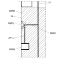
- connection terminal 33 and the light-emitting member 35 may be located closer to the second main surface 53 than to the first main surface 51, as in a non-limiting example shown in FIG. 3.
- the distance L21 between the connection terminal 33 and the light-emitting member 35 and the second main surface 53 may be smaller than the distance L22 between the connection terminal 33 and the light-emitting member 35 and the first main surface 51.
- the thickness of the holder 23 between the connection terminal 33 and the light-emitting member 35 and the first main surface 51 is easily ensured. Therefore, the restraining stability of the first cutting edge member 25 against the holder 23 is easily improved. Also, the first wiring 37 is less likely to be damaged by the first cutting edge member 25. Note that, if the distance between the connection terminal 33 and the second main surface 53 and the distance between the light-emitting member 35 and the second main surface 53 are different, the above configuration may be evaluated based on the larger distance.
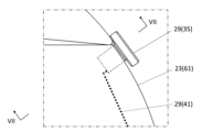
- the holder 23 may have an outer peripheral surface 61, as in the non-limiting example shown in FIG. 2.
- the light emitting member 35 may be attached to the outer peripheral surface 61. In these cases, the light emitting member 35 is easy to see.
- the main body 45 may have the outer peripheral surface 61.
- the outer peripheral surface 61 may be located between the first main surface 51 and the second main surface 53.
- the light emitting member 35 may protrude from the outer peripheral surface 61. When the light emitting member 35 protrudes, the light emitting member 35 may be located between the outer peripheral surface 61 and the diameter of the first cutting blade member 25.
- connection terminal 33 may be attached to the outer circumferential surface 61. In this case, it is easy to attach the first wiring 37 to the connection terminal 33.
- the connection terminal 33 and the light-emitting member 35 may be positioned along the circumferential direction of the holder 23.
- the first wiring 37 may be detachably attached to the connection terminal 33. In this case, it is possible to separate the first wiring 37 from the connection terminal 33 after checking the contact state of the first cutting blade member 25 and the second cutting blade member 27. Therefore, the first wiring 37 is less likely to be damaged when cutting the sheet-like member.
- the unit 1 may have a detachable connector, and the first wiring 37 may be detachably attached to the connection terminal 33 by this connector.
- the power source 31, connection terminal 33, light-emitting member 35, first wiring 37, second wiring 39, third wiring 41, and fourth wiring 43 constituting the detection means 29 do not need to be inseparably integrated, and may be partially removable.
- the third wiring 41 and fourth wiring 43 may be attached inside the body 45 of the holder 23, while members such as the light-emitting member 35 and translucent member 67 may be removable from the body 45. In such a case, when the light-emitting member 35 and translucent member 67 deteriorate, it is possible to replace only these members, and there is no need to replace the body 45 as well.
- the unit 1 may have a plurality of holders 23, first cutting blade members 25, second cutting blade members 27, and light-emitting members 35.
- the plurality of light-emitting members 35 may be arranged in a line along the first rotation axis O1, as in the non-limiting example shown in FIG. 1. In these cases, the light-emitting members 35 are easy to see.
- the multiple light-emitting members 35 can each emit light individually. Therefore, rather than performing overall detection to detect the presence or absence of contact between the multiple first cutting blade members 25 and the multiple second cutting blade members 27 collectively, individual detection to detect each individually is possible. Therefore, it is easy to efficiently detect the presence or absence of contact between the multiple first cutting blade members 25 and the multiple second cutting blade members 27, and it is easy to suppress the occurrence of cutting defects.
- the detection means 29 may have a switch 63.
- the switch 63 is capable of controlling the flow of current on and off. When the detection means 29 has a switch 63, it is possible to activate it only when it is desired to check the position of the cutting edge.
- the position of the switch 63 is not particularly limited as long as it performs its function.
- unit 1A for a cutting device on another side of the present disclosure
- unit 1A a non-limiting unit 1A for a cutting device on another side of the present disclosure
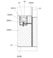
- the holder 23 may have a ring-shaped recess 65 located on the outer circumferential surface 61.
- the light-emitting member 35 may be attached to the recess 65. In these cases, the light-emitting member 35 is less likely to be damaged.
- the recess 65 may also be referred to as a groove.
- the unit 1A may further include a light-transmitting member 67.
- the light-transmitting member 67 may be attached to the recess 65, or may be in the shape of a ring that covers the light-emitting member 35. In these cases, the light-emitting member 35 is less likely to be damaged.
- Examples of the material of the light-transmitting member 67 include glass and light-transmitting resin.
- Examples of the light-transmitting resin include PMMA (PolyMethyl MethAcrylate) resin, PET (PolyEthylene Terephthalate) resin, and PC (PolyCarbonate) resin.
- the light-transmitting member 67 may have a degree of translucency such that the light-emitting member 35 can be seen through the light-transmitting member 67.
- the light-emitting member 35 may have a first light-emitting element 69 and a second light-emitting element 71, as shown in a non-limiting example in FIG. 9.
- the second light-emitting element 71 may emit light in a color different from the first light-emitting element 69. In these cases, it is possible to separately display the purpose and positional relationship of the cutting tool at the cutting site.
- connection terminal 33 may be attached to the recess 65 so as to be exposed from the translucent member 67.
- unit 1B (hereinafter sometimes referred to as "unit 1B") of this disclosure.
- the light-emitting member 35 and the connection terminal 33 may be attached to the second main surface 53. In this case, the light-emitting member 35 and the connection terminal 33 are less likely to be damaged.
- connection terminal 33 and the light-emitting member 35 may be positioned along the circumferential direction of the holder 23.
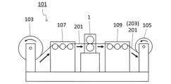
- the cutting device 101 may have a unit 1, a first roll 103, and a second roll 105, as shown in a non-limiting example in FIG. 13.
- a unit 1 When the cutting device 101 has a unit 1, cutting defects are less likely to occur.
- the first roll 103 may have the sheet-like member 201 wound around it, and may also feed the sheet-like member 201 to the unit 1.
- the first roll 103 may function as a supply mechanism that supplies the sheet-like member 201 to the unit 1.
- the first roll 103 may rotate, thereby feeding the sheet-like member 201 wound around the first roll 103 to the unit 1.
- the second roll 105 may wind up the sheet-like member 201 cut by the unit 1.
- the second roll 105 may function as a winding mechanism that winds up the sheet-like member 201 cut by the unit 1.
- the second roll 105 may be one or more. When there is one second roll 105, the sheet-like members 201 cut and individualized in unit 1 may be wound up collectively on one second roll 105. When there are multiple second rolls 105, the sheet-like members 201 cut and individualized in unit 1 may be wound up on multiple second rolls 105, respectively.
- the sheet-like members 201 cut and individualized in unit 1 may be referred to as sheet fragments 203.
- the cutting device 101 may have a first guide roll 107 located between the unit 1 and the first roll 103.
- the sheet-like member 201 can be supplied from the first roll 103 to the unit 1 through the first guide roll 107, which makes it easier to stabilize the supply state of the sheet-like member 201.
- the first guide roll 107 may be composed of one roll, or may be composed of multiple rolls.
- the cutting device 101 may have a second guide roll 109 located between the unit 1 and the second roll 105.
- the sheet fragment 203 can be transported from the unit 1 to the second roll 105 through the second guide roll 109, so that the transport state of the sheet fragment 203 is likely to be stable.
- the second guide roll 109 may be composed of one roll, or may be composed of multiple rolls.
- the cutting device 101 has a unit 1, but is not limited to this form.
- the cutting device 101 may have a unit 1A or a unit 1B.
- the sheet fragments 203 may be produced by cutting a sheet-like member 201, as shown in a non-limiting example in FIG. 13.
- the manufacturing method of the sheet fragments 203 may include the following steps: (1) a step of electrically connecting the connection terminal 33 and the first wiring 37 in the unit 1; (2) a step of confirming a contact state between the first cutting blade member 25 and the second cutting blade member 27 by a detection means 29; (3) a step of separating the first wiring 37 from the connection terminal 33; (4) cutting the sheet-like member 201 with the first cutting blade member 25 and the second cutting blade member 27; may have the following structure:
- unit 1 When unit 1 is used in the manufacturing method of sheet fragments 203, cutting defects are less likely to occur.
- Examples of the sheet-like member 201 include materials such as metal foil, paper, and resin film.
- unit 1 In the non-limiting example shown in FIG. 13, unit 1 is used, but the present invention is not limited to this form.
- unit 1A or unit 1B may be used.
- the above provides examples of the cutting device units 1, 1A, 1B, the cutting device 101, and the manufacturing method for the sheet fragments 203 on one side of the present disclosure, but it goes without saying that the present disclosure is not limited to the above embodiments, and any embodiment may be used as long as it does not deviate from the gist of the present disclosure.
- a cutting device unit includes a base, a first shaft member attached to the base and extending along a first rotation axis, a cylindrical holder attached to the first shaft member, a first annular cutting blade member attached to the holder, a second shaft member attached to the base and extending along a second rotation axis parallel to the first rotation axis, a cylindrical second cutting blade member attached to the second shaft member, and a detection means for detecting contact between the first cutting blade member and the second cutting blade member.
- the second shaft member, the first cutting blade member, and the second cutting blade member are each electrically conductive
- the detection means includes a power source, a connection terminal attached to the holder, a light emitting member attached to the holder, a first wiring electrically connecting the connection terminal and the power source, a second wiring electrically connecting the second shaft member and the power source, a third wiring electrically connecting the light emitting member and the connection terminal, and a fourth wiring electrically connecting the light emitting member and the first cutting blade member.
- the holder may have a first main surface and a second main surface located opposite the first main surface, the first cutting blade member may be in contact with the first main surface, and the connection terminal and the light-emitting member may be located closer to the second main surface than the first main surface.
- the holder may have an outer circumferential surface, and the light emitting member may be attached to the outer circumferential surface.
- any one of the units for a cutting device described above in (1) to (4) may have a plurality of the holders, the first cutting blade members, the second cutting blade members, and the light-emitting members, and the plurality of light-emitting members may be arranged in a row along the first rotation axis.
- the holder may have an outer peripheral surface and a circular ring-shaped recess located on the outer peripheral surface, and the light-emitting member may be attached to the recess.
- the unit for a cutting device according to (6) above may further include a ring-shaped light-transmitting member that is attached to the recess and covers the light-emitting member.
- the detection means may have a switch.
- the light-emitting member may have a first light-emitting element and a second light-emitting element that emits light of a color different from that of the first light-emitting element.
- the cutting device may include any one of the cutting device units (1) to (9) above, a first roll around which a sheet-like material is wound and which sends out the sheet-like material to the cutting device unit, and a second roll which winds up the sheet-like material cut by the cutting device unit.
- a method for manufacturing sheet fragments can include a step of electrically connecting the connection terminal and the first wiring in a cutting device unit of any one of (1) to (9) above, a step of checking the contact status of the first cutting blade member and the second cutting blade member by the detection means, a step of separating the first wiring from the connection terminal, and a step of cutting a sheet-like member with the first cutting blade member and the second cutting blade member.
Landscapes
- Life Sciences & Earth Sciences (AREA)
- Forests & Forestry (AREA)
- Engineering & Computer Science (AREA)
- Mechanical Engineering (AREA)
- Details Of Cutting Devices (AREA)
- Perforating, Stamping-Out Or Severing By Means Other Than Cutting (AREA)
- Laser Beam Processing (AREA)
- Polishing Bodies And Polishing Tools (AREA)
Priority Applications (5)
| Application Number | Priority Date | Filing Date | Title |
|---|---|---|---|
| CN202380063978.XA CN119744218A (zh) | 2022-09-27 | 2023-09-21 | 切断装置用单元、切断装置及片材断片的制造方法 |
| US19/114,789 US20260097536A1 (en) | 2022-09-27 | 2023-09-21 | Unit for cutting apparatus, cutting apparatus, and method for manufacturing sheet fragment |
| JP2024549276A JP7844654B2 (ja) | 2022-09-27 | 2023-09-21 | 切断装置用ユニット、切断装置及びシート断片の製造方法 |
| EP23872100.5A EP4596195A1 (en) | 2022-09-27 | 2023-09-21 | Cutting device unit, cutting device, and sheet fragment manufacturing method |
| KR1020257008447A KR20250048466A (ko) | 2022-09-27 | 2023-09-21 | 절단 장치용 유닛, 절단 장치 및 시트 단편의 제조 방법 |
Applications Claiming Priority (2)
| Application Number | Priority Date | Filing Date | Title |
|---|---|---|---|
| JP2022153604 | 2022-09-27 | ||
| JP2022-153604 | 2022-09-27 |
Publications (1)
| Publication Number | Publication Date |
|---|---|
| WO2024070873A1 true WO2024070873A1 (ja) | 2024-04-04 |
Family
ID=90477645
Family Applications (1)
| Application Number | Title | Priority Date | Filing Date |
|---|---|---|---|
| PCT/JP2023/034208 Ceased WO2024070873A1 (ja) | 2022-09-27 | 2023-09-21 | 切断装置用ユニット、切断装置及びシート断片の製造方法 |
Country Status (6)
| Country | Link |
|---|---|
| US (1) | US20260097536A1 (https=) |
| EP (1) | EP4596195A1 (https=) |
| JP (1) | JP7844654B2 (https=) |
| KR (1) | KR20250048466A (https=) |
| CN (1) | CN119744218A (https=) |
| WO (1) | WO2024070873A1 (https=) |
Citations (5)
| Publication number | Priority date | Publication date | Assignee | Title |
|---|---|---|---|---|
| JPH01321197A (ja) | 1988-06-21 | 1989-12-27 | Toshiba Tungaloy Co Ltd | テープスリッター装置 |
| JPH04122488U (ja) | 1991-04-17 | 1992-11-04 | 東洋刃物株式会社 | シートスリツター装置 |
| JP2012121098A (ja) * | 2010-12-08 | 2012-06-28 | Toray Eng Co Ltd | シート状物の切断装置 |
| JP2020055076A (ja) * | 2018-10-03 | 2020-04-09 | 株式会社フジクラ | スリッタ装置、及び、スリッタ刃の位置調整方法 |
| WO2022224813A1 (ja) * | 2021-04-19 | 2022-10-27 | 京セラ株式会社 | 切断装置用ユニット及び切断装置 |
-
2023
- 2023-09-21 WO PCT/JP2023/034208 patent/WO2024070873A1/ja not_active Ceased
- 2023-09-21 CN CN202380063978.XA patent/CN119744218A/zh active Pending
- 2023-09-21 KR KR1020257008447A patent/KR20250048466A/ko active Pending
- 2023-09-21 US US19/114,789 patent/US20260097536A1/en active Pending
- 2023-09-21 EP EP23872100.5A patent/EP4596195A1/en active Pending
- 2023-09-21 JP JP2024549276A patent/JP7844654B2/ja active Active
Patent Citations (5)
| Publication number | Priority date | Publication date | Assignee | Title |
|---|---|---|---|---|
| JPH01321197A (ja) | 1988-06-21 | 1989-12-27 | Toshiba Tungaloy Co Ltd | テープスリッター装置 |
| JPH04122488U (ja) | 1991-04-17 | 1992-11-04 | 東洋刃物株式会社 | シートスリツター装置 |
| JP2012121098A (ja) * | 2010-12-08 | 2012-06-28 | Toray Eng Co Ltd | シート状物の切断装置 |
| JP2020055076A (ja) * | 2018-10-03 | 2020-04-09 | 株式会社フジクラ | スリッタ装置、及び、スリッタ刃の位置調整方法 |
| WO2022224813A1 (ja) * | 2021-04-19 | 2022-10-27 | 京セラ株式会社 | 切断装置用ユニット及び切断装置 |
Also Published As
| Publication number | Publication date |
|---|---|
| CN119744218A (zh) | 2025-04-01 |
| JP7844654B2 (ja) | 2026-04-13 |
| KR20250048466A (ko) | 2025-04-08 |
| EP4596195A1 (en) | 2025-08-06 |
| US20260097536A1 (en) | 2026-04-09 |
| JPWO2024070873A1 (https=) | 2024-04-04 |
Similar Documents
| Publication | Publication Date | Title |
|---|---|---|
| JP7499410B2 (ja) | 切断装置用ユニット及び切断装置 | |
| US20070281499A1 (en) | Printed wiring board, its bending method, and electronic apparatus | |
| WO2024070873A1 (ja) | 切断装置用ユニット、切断装置及びシート断片の製造方法 | |
| TW201007076A (en) | Light output device and assembly method | |
| US20150198320A1 (en) | Light emitting module | |
| CN101852611A (zh) | 应用于工具的同源双线标线装置及其标线方法 | |
| JP2014226743A (ja) | カッタユニット、切断装置、切断方法及びホルダー | |
| WO2016114343A1 (ja) | 回転刃用ホルダ、切断装置用ユニット及び切断装置 | |
| JP7119233B2 (ja) | 大判成膜基板およびその製造方法、分割成膜基板およびその製造方法、分割成膜基板の生産管理方法および生産管理システム | |
| JP2016145080A (ja) | キャリアテープ及び梱包体 | |
| CN112867892B (zh) | 照明系统 | |
| JP6347239B2 (ja) | 電子部品の搬送装置およびそれを用いた産業装置 | |
| US20120069124A1 (en) | Head unit, printer, and method of manufacturing head unit | |
| JP2022071017A (ja) | スリッターナイフおよびスリッター | |
| JP4609669B2 (ja) | 静電チャックモジュール | |
| JP5613585B2 (ja) | 発光素子パッケージ基板の分割方法及び支持ジグ | |
| WO2026053643A1 (ja) | スリッター、切断装置用ユニット、及び切断装置 | |
| JP5349439B2 (ja) | ガルバノスキャナ | |
| JP2979429B2 (ja) | ラインサーマルプリンタ | |
| KR100536630B1 (ko) | 백라이트유니트용 광학시트 커팅장치의 이송커팅롤러 | |
| JP7398409B2 (ja) | オゾン発生器 | |
| KR200346873Y1 (ko) | 백라이트유니트용 광학시트 커팅장치의 이송커팅롤러 | |
| KR102520519B1 (ko) | 반사판 제조장치 | |
| JP2007083248A (ja) | レーザ加工装置及びレーザ加工方法 | |
| CN103900052A (zh) | 半导体发光元件用托座及其制造方法、元件模块、照明器具 |
Legal Events
| Date | Code | Title | Description |
|---|---|---|---|
| 121 | Ep: the epo has been informed by wipo that ep was designated in this application |
Ref document number: 23872100 Country of ref document: EP Kind code of ref document: A1 |
|
| WWE | Wipo information: entry into national phase |
Ref document number: 2024549276 Country of ref document: JP |
|
| WWE | Wipo information: entry into national phase |
Ref document number: 202380063978.X Country of ref document: CN |
|
| ENP | Entry into the national phase |
Ref document number: 20257008447 Country of ref document: KR Kind code of ref document: A |
|
| WWE | Wipo information: entry into national phase |
Ref document number: 1020257008447 Country of ref document: KR |
|
| WWP | Wipo information: published in national office |
Ref document number: 202380063978.X Country of ref document: CN |
|
| WWP | Wipo information: published in national office |
Ref document number: 1020257008447 Country of ref document: KR |
|
| WWE | Wipo information: entry into national phase |
Ref document number: 2023872100 Country of ref document: EP |
|
| NENP | Non-entry into the national phase |
Ref country code: DE |
|
| ENP | Entry into the national phase |
Ref document number: 2023872100 Country of ref document: EP Effective date: 20250428 |
|
| WWP | Wipo information: published in national office |
Ref document number: 2023872100 Country of ref document: EP |