WO2024070772A1 - スラグ監視装置、余寿命評価装置、スラグ監視方法及び余寿命評価方法 - Google Patents
スラグ監視装置、余寿命評価装置、スラグ監視方法及び余寿命評価方法 Download PDFInfo
- Publication number
- WO2024070772A1 WO2024070772A1 PCT/JP2023/033734 JP2023033734W WO2024070772A1 WO 2024070772 A1 WO2024070772 A1 WO 2024070772A1 JP 2023033734 W JP2023033734 W JP 2023033734W WO 2024070772 A1 WO2024070772 A1 WO 2024070772A1
- Authority
- WO
- WIPO (PCT)
- Prior art keywords
- temperature
- fin
- thermal resistor
- slag
- thickness
- Prior art date
- Legal status (The legal status is an assumption and is not a legal conclusion. Google has not performed a legal analysis and makes no representation as to the accuracy of the status listed.)
- Ceased
Links
Images






Classifications
-
- C—CHEMISTRY; METALLURGY
- C10—PETROLEUM, GAS OR COKE INDUSTRIES; TECHNICAL GASES CONTAINING CARBON MONOXIDE; FUELS; LUBRICANTS; PEAT
- C10J—PRODUCTION OF PRODUCER GAS, WATER-GAS, SYNTHESIS GAS FROM SOLID CARBONACEOUS MATERIAL, OR MIXTURES CONTAINING THESE GASES; CARBURETTING AIR OR OTHER GASES
- C10J3/00—Production of combustible gases containing carbon monoxide from solid carbonaceous fuels
- C10J3/46—Gasification of granular or pulverulent flues in suspension
-
- C—CHEMISTRY; METALLURGY
- C10—PETROLEUM, GAS OR COKE INDUSTRIES; TECHNICAL GASES CONTAINING CARBON MONOXIDE; FUELS; LUBRICANTS; PEAT
- C10J—PRODUCTION OF PRODUCER GAS, WATER-GAS, SYNTHESIS GAS FROM SOLID CARBONACEOUS MATERIAL, OR MIXTURES CONTAINING THESE GASES; CARBURETTING AIR OR OTHER GASES
- C10J3/00—Production of combustible gases containing carbon monoxide from solid carbonaceous fuels
- C10J3/46—Gasification of granular or pulverulent flues in suspension
- C10J3/48—Apparatus; Plants
-
- F—MECHANICAL ENGINEERING; LIGHTING; HEATING; WEAPONS; BLASTING
- F23—COMBUSTION APPARATUS; COMBUSTION PROCESSES
- F23G—CREMATION FURNACES; CONSUMING WASTE PRODUCTS BY COMBUSTION
- F23G5/00—Incineration of waste; Incinerator constructions; Details, accessories or control therefor
- F23G5/50—Control or safety arrangements
-
- F—MECHANICAL ENGINEERING; LIGHTING; HEATING; WEAPONS; BLASTING
- F27—FURNACES; KILNS; OVENS; RETORTS
- F27D—DETAILS OR ACCESSORIES OF FURNACES, KILNS, OVENS OR RETORTS, IN SO FAR AS THEY ARE OF KINDS OCCURRING IN MORE THAN ONE KIND OF FURNACE
- F27D21/00—Arrangement of monitoring devices; Arrangement of safety devices
-
- G—PHYSICS
- G01—MEASURING; TESTING
- G01K—MEASURING TEMPERATURE; MEASURING QUANTITY OF HEAT; THERMALLY-SENSITIVE ELEMENTS NOT OTHERWISE PROVIDED FOR
- G01K1/00—Details of thermometers not specially adapted for particular types of thermometer
- G01K1/14—Supports; Fastening devices; Arrangements for mounting thermometers in particular locations
-
- G—PHYSICS
- G01—MEASURING; TESTING
- G01K—MEASURING TEMPERATURE; MEASURING QUANTITY OF HEAT; THERMALLY-SENSITIVE ELEMENTS NOT OTHERWISE PROVIDED FOR
- G01K11/00—Measuring temperature based upon physical or chemical changes not covered by groups G01K3/00, G01K5/00, G01K7/00 or G01K9/00
- G01K11/32—Measuring temperature based upon physical or chemical changes not covered by groups G01K3/00, G01K5/00, G01K7/00 or G01K9/00 using changes in transmittance, scattering or luminescence in optical fibres
- G01K11/3206—Measuring temperature based upon physical or chemical changes not covered by groups G01K3/00, G01K5/00, G01K7/00 or G01K9/00 using changes in transmittance, scattering or luminescence in optical fibres at discrete locations in the fibre, e.g. using Bragg scattering
Definitions
- the present disclosure relates to a slag monitoring device, a remaining life assessment device, a slag monitoring method, and a remaining life assessment method.
- a gasification furnace configured to gasify a carbon-containing solid fuel is known (see Patent Document 1).
- the gasification furnace has a gasification section formed inside a furnace wall having a cylindrical outer shape.
- combustible components contained in the carbon-containing solid fuel e.g., pulverized coal
- a product gas mainly composed of CO and H2 a product gas mainly composed of CO and H2 , and ash in the carbon-containing solid fuel is melted and turned into slag.
- Patent Document 1 in order to prevent clogging of the opening of the slag tap, which is installed at the bottom of the gasification section of the gasification furnace and allows molten slag to flow down, a decrease in multiple temperature data points inside the slag tap, its opening, etc. is detected and signs of clogging of the opening are judged.
- Patent Document 2 discloses that the correlation between the temperature of the metal layer made of molten metal and the temperature of the slag layer is determined for each thickness of the slag layer made of molten slag. Patent Document 2 also discloses that the temperature of the slag layer is determined in a setting range based on the above correlation, so that the temperature of the metal layer is suitable for tilting when the slag is discharged, and the temperature of the slag layer is controlled taking this setting range into consideration.
- Slag may be attached to the inner surface of the furnace wall that forms the gasification section of the gasification furnace to prevent thermal damage to the furnace wall caused by heat (combustion heat) generated inside the furnace wall.
- heat combustion heat
- the gasification section is relatively high temperature (e.g., about 1800°C)
- the heat flux of the gas flowing inside the furnace wall changes at a relatively high cycle, it is difficult to determine the state of adhesion of the slag attached to the inner surface of the furnace wall using only the absolute value of the furnace wall temperature.
- the objective of at least one embodiment of the present disclosure is to provide a slag monitoring device and a slag monitoring method that can grasp the fluctuating state of slag adhesion during operation of a gasification furnace (furnace).
- a slag monitoring device includes: A slag monitoring device for monitoring the state of slag adhering to a furnace wall formed by alternately joining water-cooled tubes and fins, a fin temperature data acquisition unit configured to acquire time-series temperature data of the fin during a first predetermined period measured by at least one fin temperature measurement device provided outside the furnace wall and configured to measure the temperature of the fin; a fin temperature fluctuation range information acquisition unit configured to acquire fin temperature fluctuation range information, which is information regarding a fluctuation range of the temperature of the fin, from the time-series temperature data of the fin acquired by the fin temperature data acquisition unit; and
- the furnace wall is provided with a thermal resistor attached to an inner surface thereof, the thermal resistor being made of at least one of a refractory material or the slag, and a thermal resistor thickness estimation unit configured to estimate a thickness of the thermal resistor corresponding to the fin temperature fluctuation range information acquired by the fin temperature fluctuation range information acquisition unit based on first association information in which the fin temperature fluctuation range
- a remaining life assessment device includes: A remaining life evaluation device configured to evaluate the remaining life of a top portion of a water-cooled tube in a furnace wall formed by alternately joining water-cooled tubes and fins, a fin temperature data acquisition unit configured to acquire time-series temperature data of the fin measured by at least one fin temperature measurement device provided on the outside of the furnace wall and configured to measure the temperature of the fin; a first life evaluation value derivation unit configured to derive a first life evaluation value including a first amplitude, which is an amplitude of a temperature fluctuation for evaluating a fatigue life of the fin, and a first count number, which is an occurrence number of a temperature fluctuation for evaluating a fatigue life of the fin, using the time-series temperature data of the fin; a second life evaluation value derivation unit configured to derive a second life evaluation value corresponding to the first life evaluation value based on an amplitude ratio between a second amplitude, which is an amplitude of a temperature fluctuation for evaluating
- a method for monitoring slag includes: A slag monitoring method for monitoring the state of slag adhering to a furnace wall formed by alternately joining water-cooled tubes and fins, comprising: a fin temperature data acquisition step of acquiring time-series temperature data of the fin during a first predetermined period measured by at least one fin temperature measurement device provided outside the furnace wall and configured to measure the temperature of the fin; a fin temperature fluctuation range information acquisition step of acquiring fin temperature fluctuation range information, which is information regarding a fluctuation range of the temperature of the fin, from the time-series temperature data of the fin acquired in the fin temperature data acquisition step; and a thermal resistor thickness estimation step of estimating a thickness of the thermal resistor attached to the inner surface of the furnace wall, the thermal resistor being made of at least one of a refractory material or the slag, and a thickness of the thermal resistor corresponding to the fin temperature fluctuation range information acquired in the fin temperature fluctuation range information acquisition step, based on first association information in which the
- a remaining life assessment method includes: A remaining life evaluation method configured to evaluate the remaining life of a top portion of a water-cooled tube in a furnace wall formed by alternately joining water-cooled tubes and fins, comprising: a fin temperature data acquisition step of acquiring time-series temperature data of the fin measured by at least one fin temperature measurement device provided on the outside of the furnace wall and configured to measure the temperature of the fin; a first life evaluation value derivation step of deriving a first life evaluation value including a first amplitude, which is an amplitude of a temperature fluctuation for evaluating a fatigue life of the fin, and a first count number, which is an occurrence number of a temperature fluctuation for evaluating a fatigue life of the fin, using the time-series temperature data of the fin; a second life evaluation value derivation step configured to derive a second life evaluation value corresponding to the first life evaluation value based on an amplitude ratio between a second amplitude, which is an amplitude of a temperature fluctuation for
- At least one embodiment of the present disclosure provides a slag monitoring device and a slag monitoring method that can grasp the fluctuating state of slag adhesion during operation of a gasification furnace (furnace).
- FIG. 1 is a schematic cross-sectional view along the height direction of a gasification furnace (furnace) to which slag, which is an object to be monitored by a slag monitoring device according to an embodiment of the present disclosure, adheres.
- FIG. 2 is a schematic diagram of a furnace wall according to an embodiment of the present disclosure.
- FIG. 1 is a schematic diagram of a temperature measuring device mounted on a furnace wall and a slag monitoring device connected to the temperature measuring device according to one embodiment of the present disclosure.
- 1 is a schematic cross-sectional view of a furnace wall showing an example of a state of a thermal resistor attached to the furnace wall according to an embodiment of the present disclosure.
- FIG. 1 is a schematic cross-sectional view of a furnace wall showing an example of a state of a thermal resistor attached to the furnace wall according to an embodiment of the present disclosure.
- 1 is a schematic cross-sectional view of a furnace wall showing an example of a state of a thermal resistor attached to the furnace wall according to an embodiment of the present disclosure.
- 1 is a schematic cross-sectional view of a furnace wall showing an example of a state of a thermal resistor attached to the furnace wall according to an embodiment of the present disclosure.
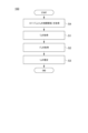
- FIG. 1 is a flow diagram of a method for monitoring slugs according to one embodiment of the present disclosure.
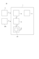
- 1 is a schematic diagram illustrating a configuration of a slag monitoring device according to an embodiment of the present disclosure;
- FIG. 1 is a schematic cross-sectional view of a furnace wall showing an example of a state of a thermal resistor attached to the furnace wall according to an embodiment of the present disclosure.
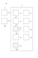
- FIG. 1 is a schematic diagram illustrating a configuration of a slag monitoring device according to an embodiment of the present disclosure
- 4 is an explanatory diagram for explaining a peeling estimation unit and a thermal resistor thickness increase rate calculation unit according to an embodiment of the present disclosure.
- FIG. 4 is an explanatory diagram for explaining a separation estimation unit and a thermal resistor flow-down speed calculation unit according to an embodiment of the present disclosure.
- FIG. 2 is an explanatory diagram for explaining a slag generation behavior evaluation unit according to an embodiment of the present disclosure.
- 4 is an explanatory diagram for explaining a separation estimation unit and a gas circumferential flow velocity calculation unit according to an embodiment of the present disclosure.
- FIG. 1 is a schematic diagram illustrating a configuration of a slag monitoring device according to an embodiment of the present disclosure
- FIG. 1 is a flow diagram of a method for monitoring slugs according to one embodiment of the present disclosure.
- 11 is an explanatory diagram for explaining a corresponding fin temperature variation range information acquisition unit and an error range derivation unit according to an embodiment of the present disclosure.
- FIG. 10 is an explanatory diagram for explaining a first association information correction unit according to an embodiment of the present disclosure.
- FIG. FIG. 2 is a schematic diagram of a furnace wall according to an embodiment of the present disclosure.
- 1 is a schematic diagram illustrating a configuration of a remaining life assessment device according to an embodiment of the present disclosure;
- FIG. 2 is a flow diagram of a remaining life assessment method according to an embodiment of the present disclosure.
- FIG. 11 is an explanatory diagram for explaining a method for deriving a life evaluation value according to an embodiment of the present disclosure.
- FIG. 13 is an explanatory diagram for explaining the correlation coefficient between the fin temperature and the tube top temperature according to an embodiment of the present disclosure.
- 1 is an explanatory diagram for explaining a method for deriving a life evaluation value for evaluating the life of a pipe tip portion of a water-cooled pipe according to an embodiment of the present disclosure.
- FIG. 11 is an explanatory diagram for explaining a method for deriving a life evaluation value according to an embodiment of the present disclosure.
- FIG. 13 is an explanatory diagram for explaining the correlation coefficient between the fin temperature and the tube top temperature according to an embodiment of the present disclosure.
- 1 is an explanatory diagram for explaining a method for deriving a life evaluation value for evaluating the life of a pipe tip portion of a water-cooled pipe according to an
- FIG. 1 is a schematic cross-sectional view along the height direction of a gasification furnace 2A (furnace 2) to which slag 31, which is a monitoring target in a slag monitoring device 1 according to an embodiment of the present disclosure, adheres.
- FIG. 2 is a schematic view of a furnace wall 21 according to an embodiment of the present disclosure.
- FIG. 3 is a schematic view of a temperature measuring device (such as a fin temperature measuring device 4) attached to a furnace wall 21 according to an embodiment of the present disclosure and a slag monitoring device 1 connected to the temperature measuring device.
- Each of the slag monitoring device 1 and the slag monitoring method 100 is for monitoring the state of slag 31 (thermal resistor 3) adhering to the inner surface 211 of the furnace wall 21 mounted on a gasification furnace 2A (furnace 2) as shown in FIG. 1.
- a gasification furnace 2A configured to gasify a carbon-containing solid fuel
- the present disclosure is also applicable to cases in which the furnace 2 is other than a gasification furnace 2A.
- a gasification section 24 formed inside the furnace wall 21 by the inner surface 211 of the furnace wall 21, and an annulus section 26 formed between the furnace wall 21 and a furnace outer wall 25 covering the outer periphery of the furnace wall 21 are formed inside the gasification furnace 2A.
- the gasification section 24 is configured to gasify combustible components contained in a carbon-containing solid fuel (e.g., pulverized coal) by causing a combustion reaction with oxygen to generate a generated gas mainly composed of CO and H2 , and is configured to melt ash in the carbon-containing solid fuel to turn it into slag 31.
- a carbon-containing solid fuel e.g., pulverized coal
- the annulus portion 26 is formed outside the furnace wall 21 by the outer surface 212 of the furnace wall 21 and the inner surface 251 of the furnace outer wall 25.
- the furnace outer wall 25 is formed in a cylindrical shape that extends along the height direction of the furnace wall 21 and separates the inside and outside of the gasification furnace 2A.
- the gasification furnace 2A is attached to the furnace wall 21 at the annulus portion 26 and has at least one burner device 27 (multiple in the illustrated example) for combusting the carbon-containing solid fuel guided to the gasification portion 24.
- the furnace wall 21 is formed by alternately joining water-cooled pipes 22 and fins 23.
- the furnace wall 21 is formed in a cylindrical shape extending along the height direction of the furnace wall 21.
- the furnace wall 21 has a height direction along the vertical direction.
- Each of the multiple water-cooled pipes 22 is a pipe extending along the height direction of the furnace wall 21, and cooling water (cooling liquid, circulating water) flows through the inside of the pipe.
- the furnace wall 21 is cooled by the cooling water flowing through the water-cooled pipe 22.
- Each of the multiple water-cooled pipes 22 is arranged at intervals between the other water-cooled pipes 22 along the circumferential direction of the furnace wall 21.
- Each of the multiple fins 23 is formed in a plate shape extending along the height direction of the furnace wall 21, and is arranged between two adjacent water-cooled pipes 22, 22 in the circumferential direction of the furnace wall 21.
- the multiple water-cooled pipes 22 and the multiple fins 23 are made of a metal material.
- Each of the multiple fins 23 has one end in the width direction of the fin 23 joined to one of the two adjacent water-cooled pipes 22, 22 described above by welding or the like, and the other end in the width direction of the fin 23 joined to the other of the two adjacent water-cooled pipes 22, 22 described above by welding or the like.
- Thermal resistor 4 to 7 are schematic cross-sectional views of a furnace wall showing an example of a state of a thermal resistor 3 attached to the furnace wall 21 according to an embodiment of the present disclosure. As shown in Fig. 4 to 7, the thermal resistor 3 is attached to the inner surface 211 of the furnace wall 21.
- the thermal resistor 3 can suppress thermal damage to the furnace wall 21 caused by heat (combustion heat) generated inside the furnace wall 21, and can protect the furnace wall 21.
- the thermal resistor 3 is composed of at least one of the slag 31 and the refractory material 32 described above.
- the state of attachment of the thermal resistor 3 to the furnace wall 21 changes during operation of the gasification furnace 2A.
- the attachment state of the thermal resistor 3 can be classified into four forms (first form to fourth form) shown in Figs. 4 to 7, respectively.
- the attachment state of the thermal resistor 3 is in the first form (see Fig. 4).
- the thermal resistor 3 according to the first form does not include the slag 31, and is composed of a refractory material (refractory material) 32 attached to the inner surface 211 of the furnace wall 21.
- the refractory material 32 is attached around the entire circumference of the inner surface 211 of the furnace wall 21 so as to cover the inner surface 211 of the furnace wall 21.
- the refractory material 32 attached to the inner surface 211 of the furnace wall 21 melts due to the heat (combustion heat) generated inside the furnace wall 21 during operation of the gasification furnace 2A, and the thickness of the refractory material 32 gradually decreases.
- the adhesion state of the thermal resistor 3 changes from the first form to the second form (see FIG. 5), then from the second form to the third form (see FIG. 6), and then from the third form to the fourth form (see FIG. 7).
- the slag 31 is generated when at least one of the fuel or the combustion object of the gasification furnace 2A melts due to combustion inside the furnace wall 21, and adheres to the inner surface 211 of the furnace wall 21, etc.
- the slag 31 adheres to the surface of the refractory material 32 (the surface opposite the thickness direction of the refractory material 32 from the surface abutting the inner surface 211).
- the refractory material 32 and the slag 31 are layered in this order on the inner surface 211 of the furnace wall 21.
- the pulverized coal supplied inside the furnace wall 21 is burned by the burner device 27, and the molten slag 31 adheres to the inner surface 211 of the furnace wall 21 or the surface of the refractory material 32.
- the thermal resistor 3 in the second embodiment is composed of a refractory material 32 attached to the inner surface 211 of the furnace wall 21, and slag 31 attached to the surface of the refractory material 32, as shown in FIG. 5.
- a part of the inner surface 211 of the furnace wall 21 (specifically, the water-cooled tube 22) is not covered by the refractory material 32, but is directly covered by the slag 31.
- the thermal resistor 3 in the third embodiment is composed of a refractory material 32 attached to the inner surface 211 of the furnace wall 21, and slag 31 attached to the surface of the refractory material 32 and to the inner surface 211 of the furnace wall 21, as shown in FIG. 6.
- the inner surface 211 of the furnace wall 21 (water-cooled tubes 22 and fins 23) is not covered with the refractory material 32, but is directly covered with the slag 31.
- the thermal resistor 3 in the fourth form does not include the refractory material 32, and is composed of the slag 31 attached to the inner surface 211 of the furnace wall 21.
- the thickness ts (the sum of the thickness of the refractory material 32 and the thickness of the slag 31) of the thermal resistor 3 attached to the inner surface 211 of the furnace wall 21 gradually decreases from the first form to the fourth form.
- the slag monitoring device 1 is connected to at least one fin temperature measuring device 4 and is configured to be able to acquire the temperature Ts of the fin 23 measured by the at least one fin temperature measuring device 4.
- the at least one fin temperature measuring device 4 described above is provided in the annulus portion 26, which is the outside of the furnace wall 21, and is configured to measure the temperature (metal temperature) Ts of the fin 23.
- the at least one fin temperature measuring device 4 described above is configured to measure the temperature Ts of the fin 23 at a sensing portion 41 attached to the outer surface 231 of the fin 23.
- the at least one fin temperature measuring device 4 described above is composed of at least one optical fiber sensor 40.
- the optical fiber sensor 40 includes an optical fiber cable 42 which is a transmission path for transmitting an optical signal, a plurality of sensing units 41 provided on the optical fiber cable 42, and a measuring instrument 43 configured to be able to transmit and receive optical signals.
- the measuring instrument 43 includes a light emitting unit (light source) 44 and a light receiving unit (light receiving element) 45.
- the fin temperature measuring device 4 is not limited to the optical fiber sensor 40 as long as it is provided on the outside of the furnace wall 21 and configured to measure the temperature (metal temperature) Ts of the fin 23.
- the optical fiber cable 42 has a concentric structure in which a core with a relatively high refractive index is covered by a cladding with a relatively low refractive index, and light (optical signal) is propagated while being confined inside the core.
- Each of the multiple sensing units 41 acquires the temperature Ts of the fins 23 by utilizing the property of light changing with changes in the temperature Ts of the fins 23.
- Each of the multiple sensing units 41 may be a detection element (FGB) present in the core of the optical fiber cable 42, or may be configured integrally with the optical fiber cable 42. Also, each of the multiple sensing units 41 may be separate from the optical fiber cable 42 and detachably connected to the optical fiber cable 42.
- FGB detection element
- the light emitted from the irradiation unit 44 is guided to each of the multiple sensing units 41 via the optical fiber cable 42.
- the light guided to the sensing unit 41 changes in response to changes in the temperature Ts of the fin 23.
- the reflected light from the sensing unit 41 which changes in response to changes in the temperature Ts of the fin 23, is guided to the light receiving unit 45 via the optical fiber cable 42.
- the measuring instrument 43 detects the change in the temperature Ts of the fin 23 to which the sensing unit 41 is attached as a change in the reflected light guided to the light receiving unit 45 (for example, a change in the wavelength of the reflected light).
- the slag monitoring device 1 is connected to the measuring instrument 43 and is configured to be able to acquire the temperature Ts of the fin 23 measured at each of the multiple sensing units 41.
- FIG. 8 is a flow diagram of a slag monitoring method 100 according to an embodiment of the present disclosure.
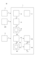
- FIG. 9 is a schematic diagram showing the configuration of a slag monitoring device 1 according to an embodiment of the present disclosure.
- the slag monitoring method 100 includes a fin temperature data acquisition step S1, a fin temperature fluctuation range information acquisition step S2, and a thermal resistance thickness estimation step S3.
- Some steps in the slag monitoring method 100 may be performed by devices or equipment included in a slag monitoring system 10 such as the slag monitoring device 1, or may be performed by devices or equipment other than the slag monitoring system 10.
- Some steps in the slag monitoring method 100 may also be performed manually.
- the slag monitoring device 1 includes a fin temperature data acquisition unit 12, a fin temperature fluctuation range information acquisition unit 13, and a thermal resistor thickness estimation unit 14. As shown in FIG. 9, the slag monitoring device 1 may further include a memory unit 11. In the illustrated embodiment, as shown in FIG. 2, the slag monitoring device 1 is mounted on a slag monitoring system 10.
- the slag monitoring system 10 includes the slag monitoring device 1 and at least one fin temperature measuring device 4 connected to the slag monitoring device 1.
- the slag monitoring device 1 is an electronic control unit for monitoring the state of the slag 31 (thermal resistor 3), and may be configured as a microcomputer including a CPU (processor) (not shown), memories such as ROM and RAM, storage devices such as external storage devices, an I/O interface, and a communication interface.
- the above-mentioned sections may be realized by the CPU operating (e.g., calculating data) according to the instructions of a program loaded into the main storage section of the memory.
- the processing contents of the slag monitoring device 1 may be implemented as a program executed by the processor and stored in the auxiliary storage section. When the programs are executed, these programs are expanded in the memory.
- the processor reads the programs from the memory and executes the instructions contained in the programs.
- fin temperature data acquisition step S1 time-series temperature data is acquired, which is time-series data of the temperature Ts of the fin 23 during the first predetermined period measured by at least one fin temperature measuring device 4 described above.
- the fin temperature data acquisition step S1 may be performed by the fin temperature data acquisition unit 12.
- the fin temperature data acquisition unit 12 is configured to acquire time-series temperature data of the fin 23 during the first predetermined period measured by at least one fin temperature measuring device 4 described above.
- the fin temperature data acquisition unit 12 may acquire the time-series temperature data of the fin 23 directly from the fin temperature measuring device 4 (in the illustrated example, the measuring device 43), or may acquire the time-series temperature data of the fin 23 sent from the fin temperature measuring device 4 (in the illustrated example, the measuring device 43) to the storage unit 11 and stored in the storage unit 11.
- the length, start point, and end point of the first predetermined period may be set in advance.
- the end point of the first predetermined period may be the time when the time-series temperature data of the fin 23 is acquired.
- fin temperature fluctuation range information acquisition step S2 fin temperature fluctuation range information ITs, which is information regarding the fluctuation range of the temperature of the fins 23, is acquired from the time-series temperature data of the fins 23 acquired in the fin temperature data acquisition step S1 (fin temperature data acquisition unit 12).
- the fin temperature fluctuation range information acquisition step S2 may be performed by the fin temperature fluctuation range information acquisition unit 13.
- the fin temperature fluctuation range information acquisition unit 13 is configured to acquire the fin temperature fluctuation range information ITs from the time-series temperature data of the fins 23 acquired in the fin temperature data acquisition step S1 (fin temperature data acquisition unit 12).
- the fin temperature fluctuation range information ITs is information that can acquire the maximum value Tsmax, the minimum value Tsmin, and the fluctuation range ⁇ Ts, which is the difference between the maximum value Tsmax and the minimum value Tsmin, of the temperature Ts of the fin 23 during the first specified period.
- the fin temperature fluctuation range information ITs may be a combination of the maximum value Tsmax and the minimum value Tsmin, or a combination of either the maximum value Tsmax or the minimum value Tsmin and the fluctuation range ⁇ Ts, or a combination of the maximum value Tsmax, the minimum value Tsmin and the fluctuation range ⁇ Ts.
- the thickness ts of the thermal resistor 3 corresponding to the fin temperature fluctuation range information ITs acquired by the fin temperature fluctuation range information acquisition step S2 is estimated based on the first association information AI1 in which the thickness ts of the thermal resistor 3 attached to the inner surface 211 of the furnace wall 21 and the fin temperature fluctuation range information ITs are associated.
- the thermal resistor thickness estimation step S3 may be performed by the thermal resistor thickness estimation unit 14.
- the thermal resistor thickness estimation unit 14 estimates the thickness ts of the thermal resistor 3 corresponding to the fin temperature fluctuation range information ITs acquired by the fin temperature fluctuation range information acquisition step S2 (fin temperature fluctuation range information acquisition unit 13) based on the first association information AI1.
- the first association information AI1 indicates the correspondence between the fin temperature fluctuation range information ITs and the thickness ts of the thermal resistor 3, and when the fin temperature fluctuation range information ITs is input information, it is sufficient that the thickness ts of the thermal resistor 3 corresponding to the fin temperature fluctuation range information ITs, which is the input information, can be obtained as output information.
- the first association information AI1 includes lists, tables, maps, functions, machine learning models, etc. that indicate the correspondence between the input information and the output information.
- the first association information AI1 may be created based on steady-state test data, or may be created based on past actual values, experimental values, numerical analysis results, etc. other than steady-state test data.
- the first association information AI1 is acquired in advance before the fin temperature data acquisition step S1.
- the slag monitoring method 100 may further include a first association information acquisition step S4 for acquiring the first association information AI1 before the fin temperature data acquisition step S1.
- the first association information AI1 may be stored in the memory unit 11 in advance, and the thermal resistor thickness estimation unit 14 may refer to the first association information AI1 stored in the memory unit 11 when estimating the thickness ts of the thermal resistor 3.
- the slag monitoring method 100 includes the above-mentioned fin temperature data acquisition step S1, the above-mentioned fin temperature fluctuation range information acquisition step S2, and the above-mentioned thermal resistor thickness estimation step S3.
- the slag monitoring device 1 includes the above-mentioned fin temperature data acquisition unit 12, the above-mentioned fin temperature fluctuation range information acquisition unit 13, and the above-mentioned thermal resistor thickness estimation unit 14.
- the slag monitoring method 100 and the slag monitoring device 1 can obtain the fin temperature fluctuation range information ITs from the temperature Ts of the fin 23 measured by the fin temperature measuring device 4, and can estimate the thickness ts of the corresponding thermal resistor 3 based on the first association information AI1 from this fin temperature fluctuation range information ITs. Since the fin temperature fluctuation range information ITs is information on the fluctuation range of the temperature Ts of the fin 23, it reflects the influence of the heat flux of the gas flowing inside the furnace wall 21, which fluctuates at a relatively high cycle inside the furnace wall 21, compared to the measured value (absolute value) of the temperature Ts of the fin 23.
- the thickness ts of the thermal resistor 3 based on the information (first association information) that associates the fin temperature fluctuation range information ITs with the thickness ts of the thermal resistor 3, it is possible to estimate the thickness ts of the thermal resistor 3 (slag 31) that reflects the influence of the heat flux of the gas flowing inside the furnace wall 21.
- the slag monitoring method 100 and the slag monitoring device 1 can accurately estimate the thickness ts of the thermal resistor 3 while the gasifier 2A is in operation, compared to when the thickness ts of the thermal resistor 3 is estimated based on information relating the measured value of the temperature Ts of the fin 23 and the thickness ts of the thermal resistor 3, and therefore can grasp the adhesion state of the thermal resistor 3 (e.g., slag 31) while the gasifier 2A is in operation.
- the thermal resistor 3 e.g., slag 31
- the adhesion state of the thermal resistor 3 (e.g., slag 31) during operation of the gasifier 2A, it is possible to evaluate the fall-off of the refractory material 32 and to understand the areas of the furnace wall 21 where the heat load is high, and it is possible to optimize the operating parameters of the gasifier 2A, such as the burner load and fuel conditions.
- the adhesion state of the thermal resistor 3 (e.g., slag 31) during operation of the gasifier 2A, it is possible to consider and create a maintenance plan for when operation is stopped without having to measure the thickness ts of the thermal resistor 3 from inside the furnace wall 21 after operation of the gasifier 2A is stopped, which makes it possible to shorten the process during regular inspections.
- the fin temperature fluctuation range information acquisition unit 13 described above is configured to acquire, as the fin temperature fluctuation range information ITs, the fluctuation range of the difference value between the temperature Ts of the fin 23 acquired by the fin temperature data acquisition unit 12 and the temperature (representative temperature) Tw of the cooling liquid flowing through the water-cooled pipe 22 during the first predetermined period described above.
- the temperature Tw of the cooling liquid flowing through the water-cooled pipe 22 may be acquired by the temperature sensor 220.
- the fin temperature fluctuation range information acquisition unit 13 may acquire the time-series temperature data of the cooling liquid directly from the temperature sensor 220, or may acquire the time-series temperature data of the cooling liquid sent from the temperature sensor 220 to the memory unit 11 and stored in the memory unit 11.
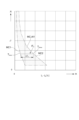
- the first association information AI1 may indicate a correspondence relationship between the difference between the temperature Ts of the fins 23 and the temperature Tw of the coolant, and the thickness ts of the thermal resistor 3, as shown in Fig. 10.
- the first association information AI1 may be configured to acquire the thickness ts of the thermal resistor 3 as output information when the difference between the temperature Ts of the fins 23 and the temperature Tw of the coolant is input information.
- the output information of the first association information AI1 and the thickness ts of the thermal resistor 3 estimated by the thermal resistor thickness estimator 14 may be the thickness ts1 of the portion attached to the inner surface of the water-cooled pipe 22, or the thickness ts2 of the portion attached to the inner surface of the fin 23, as shown in Figs. 4 to 7.
- the difference between the temperature Ts of the fins 23 and the temperature Tw of the coolant is used as the fin temperature fluctuation range information ITs, so that the temperature fluctuation of the fins 23 can be expressed as a heat quantity.
- the fin temperature fluctuation range information ITs which expresses the temperature fluctuation of the fins 23 as a heat quantity
- the slag monitoring device 1 can accurately estimate the thickness ts of the thermal resistor 3 during operation of the gasification furnace 2A, in which the heat flux of the gas flowing inside the furnace wall 21 fluctuates, compared to when using fin temperature fluctuation range information ITs, which expresses the temperature fluctuation of the fins 23 directly as a temperature change of the fins 23.
- the above-mentioned first association information AI1 includes first correspondence information MC1 and second correspondence information MC2, as shown in FIG. 10.
- the first correspondence information MC1 is information regarding the correspondence between the thickness ts of the thermal resistor 3 calculated by thermal analysis using a first heat flux as the heat flux of the gas flowing inside the furnace wall 21 and the fin temperature fluctuation range information ITs.
- the second correspondence information MC2 is information regarding the correspondence between the thickness ts of the thermal resistor 3 calculated by thermal analysis using a second heat flux larger than the first heat flux as the heat flux of the gas flowing inside the furnace wall 21 and the fin temperature fluctuation range information ITs.
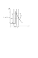
- the first association information AI1 may be a master curve MC shown on a graph, as shown in FIG. 10, in which the horizontal axis (first axis) is the difference between the temperature Ts of the fin 23 and the temperature Tw of the coolant, and the vertical axis (second axis) is the thickness ts of the thermal resistor 3.
- the first heat flux may be the lower limit of the heat flux setting
- the second heat flux may be the upper limit of the heat flux setting.
- the first correspondence information MC1 may include a lower limit boundary line in the master curve MC
- the second correspondence information MC2 may include an upper limit boundary line in the master curve MC.
- the first association information AI1 includes multiple pieces of correspondence relationship information MC1, MC2, each of which has a different heat flux of the gas flowing inside the furnace wall 21, which is one of the parameters used in thermal analysis, so that the slag monitoring device 1 can accurately estimate the thickness ts of the thermal resistor 3 (slag 31) that reflects the influence of the heat flux of the gas flowing inside the furnace wall 21.
- FIG. 11 is a schematic diagram showing the configuration of the slag monitoring device 1 according to an embodiment of the present disclosure.
- Fig. 12 is an explanatory diagram for explaining the peeling estimation unit 15 and the thermal resistor thickness increase rate calculation unit 16 according to an embodiment of the present disclosure.
- the above-mentioned slag monitoring device 1 further includes a peeling estimation unit 15. As shown in Fig.
- the peeling estimation unit 15 is configured to estimate that at least a part of the thermal resistor 3 has peeled off from the furnace wall 21 when the increase rate ⁇ c of the temperature Ts of the fin 23 measured by at least one of the fin temperature measuring devices 4 described above exceeds a predetermined temperature increase rate S ⁇ c.
- the peeling estimation unit 15 acquires time series temperature data of the fins 23 for the first predetermined period acquired in the fin temperature data acquisition step S1 (fin temperature data acquisition unit 12) as shown in FIG. 12, and time series temperature data of the difference between the temperature Ts of the fins 23 and the temperature Tw of the coolant for the first predetermined period calculated from the time series temperature data of the coolant for the first predetermined period (hereinafter referred to as corrected time series temperature data of the fins 23), and calculates the rate of increase ⁇ c of the temperature Ts of the fins 23.
- the rate of increase ⁇ c of the temperature Ts of the fins 23 is the amount of increase in the difference between the temperature Ts of the fins 23 and the temperature Tw of the coolant at each predetermined time T1 when the corrected time series temperature data of the fins 23 is divided into predetermined times T1 (the difference between the maximum and minimum values of the difference at the predetermined time T1, see FIG. 12). Note that the rate of increase ⁇ c of the temperature Ts of the fins 23 may also be the amount of increase in the temperature Ts of the fins 23 at the predetermined time T1 (the difference between the maximum and minimum values at the predetermined time T1).
- the peeling estimation unit 15 utilizes the fact that the temperature Ts of the fins 23 rises rapidly when the thermal resistor 3 peels off from the furnace wall 21, and estimates that at least a part of the thermal resistor 3 has peeled off in the portion where the rate of increase ⁇ c of the temperature Ts of the fins 23 exceeds a predetermined temperature increase rate S ⁇ c.
- the slag monitoring device 1 can estimate the peeling of the thermal resistor 3 from the time-series temperature data of the fins 23.
- the slag monitoring device 1 further includes a thermal resistor thickness increase rate calculation unit 16.
- the thermal resistor thickness increase rate calculation unit 16 is configured to calculate the increase rate of the thickness ts of the thermal resistor 3 corresponding to the decrease rate ⁇ d of the temperature Ts of the fin 23, based on the second association information AI2 in which the decrease rate ⁇ d of the temperature Ts of the fin 23 measured by the at least one fin temperature measuring device 4 is associated with the increase rate of the thickness ts of the thermal resistor 3.
- the thermal resistor thickness increase rate calculation unit 16 acquires time series temperature data of the fins 23 in the first predetermined period acquired in the fin temperature data acquisition step S1 (fin temperature data acquisition unit 12) as shown in FIG. 12, and time series temperature data of the difference between the temperature Ts of the fins 23 and the temperature Tw of the coolant in the first predetermined period calculated from the time series temperature data of the coolant in the first predetermined period (hereinafter referred to as corrected time series temperature data of the fins 23), and calculates the rate of decrease ⁇ d of the temperature Ts of the fins 23.
- the rate of decrease ⁇ d of the temperature Ts of the fin 23 is the amount of decrease in the difference between the temperature Ts of the fin 23 and the temperature Tw of the coolant at each predetermined time T1 when the corrected time series temperature data of the fin 23 is divided into each predetermined time T1 (the difference between the maximum and minimum values of the difference at the predetermined time T1, see FIG. 12).
- the rate of decrease ⁇ d of the temperature Ts of the fin 23 may also be the amount of decrease in the temperature Ts of the fin 23 at the predetermined time T1 (the difference between the maximum and minimum values at the predetermined time T1).
- the rate of increase in the thickness ts of the thermal resistor 3 may also be the amount of increase in the thickness ts at each predetermined time T1.
- the second association information AI2 indicates the correspondence between the rate of decrease ⁇ d of the temperature Ts of the fin 23 and the rate of increase ts of the thickness of the thermal resistor 3, and when the rate of decrease ⁇ d is input information, it is sufficient that the rate of increase ts of the thickness of the thermal resistor 3 corresponding to the rate of decrease ⁇ d, which is the input information, can be obtained as output information.
- the second association information AI2 includes a list, table, map, function, machine learning model, etc., indicating the correspondence between the input information and the output information.
- the second association information AI2 may be created based on steady-state test data, or may be created based on past actual values, experimental values, numerical analysis results, etc. other than steady-state test data.
- the second association information AI2 may be stored in the memory unit 11, and the thermal resistor thickness increase rate calculation unit 16 may be configured to refer to the second association information AI2 stored in the memory unit 11.
- the thermal resistor thickness increase rate calculation unit 16 can calculate the increase rate of the thickness of the thermal resistor 3 corresponding to the rate of decrease ⁇ d of the temperature Ts of the fin 23 using the second association information AI2 indicating the relationship between the rate of decrease ⁇ d of the temperature Ts of the fin 23 and the increase rate of the thickness ts of the thermal resistor 3.
- the slag monitoring device 1 can accurately estimate the thickness ts of the thermal resistor 3 during operation of the gasification furnace 2A by taking into account the rate of increase in the thickness ts of the thermal resistor 3 calculated by the thermal resistor thickness increase rate calculation unit 16.
- the at least one fin temperature measuring device 4 described above includes a first fin temperature measuring device 4A and a second fin temperature measuring device 4B arranged at a predetermined first measurement distance dv from the first fin temperature measuring device 4A in the height direction of the furnace wall 21, as shown in FIG.
- the predetermined first measurement distance dv is the distance between the temperature measurement position of the first fin temperature measuring device 4A and the temperature measurement position of the second fin temperature measuring device 4B.
- the temperature measurement position of the first fin temperature measuring device 4A is located above the temperature measurement position of the second fin temperature measuring device 4B by the first measurement distance dv in the height direction of the furnace wall 21.
- the first fin temperature measuring device 4A includes a first sensing unit 41A of the multiple sensing units 41
- the second fin temperature measuring device 4B includes a second sensing unit 41B of the multiple sensing units 41 that is located below the first sensing unit 41A in the height direction of the furnace wall 21 by the first measurement distance dv.
- FIG. 13 is an explanatory diagram for explaining the peeling estimation unit 15 and the thermal resistor flow rate calculation unit 17 according to one embodiment of the present disclosure.
- FIG. 13 shows a graph with time T on the horizontal axis and the difference between the temperature Ts of the fin 23 and the temperature Tw of the coolant on the vertical axis.
- the upper side of the graph in FIG. 13 shows corrected time series temperature data of the fin 23 derived from the measurement results of the first fin temperature measuring device 4A
- the lower side of the graph in FIG. 13 shows corrected time series temperature data of the fin 23 derived from the measurement results of the second fin temperature measuring device 4B.
- the above-mentioned peeling estimation unit 15 is configured to estimate the peeling state of the thermal resistor 3 from the furnace wall 21, taking into account the rate of increase ⁇ c ( ⁇ c1) of the temperature Ts of the fin 23 measured by the first fin temperature measuring device 4A within the second specified period T2, and the rate of increase ⁇ c ( ⁇ c2) of the temperature Ts of the fin 23 measured by the second fin temperature measuring device 4B within the second specified period T2.
- the second predetermined period T2 may be the same as the above-mentioned predetermined time T1 used to estimate peeling by each fin temperature measuring device 4, or may be longer than the predetermined time T1.
- the peeling estimation unit 15 estimates that peeling of the thermal resistor 3 has occurred in the height direction range from the temperature measurement position of the first fin temperature measuring device 4A to the temperature measurement position of the second fin temperature measuring device 4B.
- the slag monitoring device 1 can estimate the range in the height direction of the furnace wall 21 where the thermal resistor 3 has peeled off by taking into account the rate of increase ⁇ c ( ⁇ c1, ⁇ c2) of the temperature Ts of the fin 23 at multiple different positions in the height direction of the furnace wall 21, and can therefore accurately estimate the thickness distribution of the thermal resistor 3 (particularly the thickness distribution in the height direction of the furnace wall 21) while the gasification furnace 2A is in operation.
- the above-mentioned slag monitoring device 1 further includes a thermal resistor flow-down speed calculation unit 17.
- the thermal resistor flow-down speed calculation unit 17 is configured to calculate the flow-down speed Vs of the thermal resistor 3 when the above-mentioned increase rates ⁇ c1 and ⁇ c2 each exceed a predetermined temperature increase rate S ⁇ c within the second predetermined period T2.
- the acquisition time of the maximum value of the temperature Ts (corrected time-series temperature data) of the fin 23 measured by the first fin temperature measurement device 4A within the second predetermined period T2 when the increase rates ⁇ c1 and ⁇ c2 each exceed the temperature increase rate S ⁇ c is defined as the first acquisition time tp1
- the acquisition time of the maximum value of the temperature Ts (corrected time-series temperature data) of the fin 23 measured by the second fin temperature measurement device 4B within the second predetermined period T2 when the increase rates ⁇ c1 and ⁇ c2 each exceed the temperature increase rate S ⁇ c is defined as the second acquisition time tp2.
- the slag monitoring device 1 can determine that a relatively thick layer of slag 31 (thermal resistor 3) is flowing down.
- the thermal resistor flow velocity calculation unit 17 can calculate the flow velocity Vs of the thermal resistor 3.
- the slag monitoring device 1 can accurately estimate the thickness distribution of the thermal resistor 3 (particularly the thickness distribution in the height direction of the furnace wall 21) during operation of the gasification furnace 2A.
- the slag monitoring device 1 further includes a slag generation behavior evaluation unit 18.
- the slag generation behavior evaluation unit 18 is configured to evaluate the generation behavior of the slag 31 based on the decrease rate ⁇ d of the temperature Ts (corrected time-series temperature data) of the fin 23 measured by the at least one fin temperature measuring device 4 described above and the flow-down speed Vs of the thermal resistor 3 calculated by the thermal resistor flow-down speed calculation unit 17.
- FIG. 14 is an explanatory diagram for explaining the slag generation behavior evaluation unit 18 according to one embodiment of the present disclosure.
- the slag generation behavior evaluation unit 18 evaluates the generation behavior of the slag 31 by dividing it into four patterns: a first pattern D1, a second pattern D2, a third pattern D3, and a fourth pattern.
- the slag generation behavior evaluation unit 18 judges that the pattern belongs to the first pattern D1. In this case, the slag generation behavior evaluation unit 18 evaluates that the gas flow inside the furnace wall 21 is relatively large and the amount of slag 31 attached in the height direction range of the furnace wall 21 is relatively large.
- the slag generation behavior evaluation unit 18 judges that the pattern belongs to the second pattern D2 when the decrease rate ⁇ d is larger than the boundary value B ⁇ d of the decrease rate and the flow velocity Vs is smaller than the boundary value BVs of the flow velocity. In this case, the slag generation behavior evaluation unit 18 evaluates that the gas flow inside the furnace wall 21 is smaller than that in the case of the first pattern D1, and that the thick layer of slag 31 attached to the upper part of the furnace wall 21 in the height direction flows downward.
- the slag generation behavior evaluation unit 18 judges that the pattern belongs to the third pattern D3 when the decrease rate ⁇ d is smaller than the boundary value B ⁇ d of the decrease rate and the flow velocity Vs is larger than the boundary value BVs of the flow velocity. In this case, the slag generation behavior evaluation unit 18 evaluates that the gas flow inside the furnace wall 21 is smaller than that in the case of the second pattern D2, and that the thickness ts of the slag 31 gradually increases in the height direction range of the furnace wall 21.
- the slag generation behavior evaluation unit 18 judges that the fourth pattern D4 exists when the rate of decrease ⁇ d is smaller than the boundary value B ⁇ d of the rate of decrease and the flow velocity Vs is smaller than the boundary value BVs of the flow velocity. In this case, the slag generation behavior evaluation unit 18 evaluates that the gas flow inside the furnace wall 21 is smaller than that in the third pattern D3, the amount of slag 31 attached in the height direction range of the furnace wall 21 is small, and the flow of the slag 31 is also small.
- the slag generation behavior evaluation unit 18 can classify the generation behavior of the slag 31 using the rate of decrease ⁇ d of the temperature Ts of the fins 23 and the flow velocity Vs of the thermal resistor 3, and can evaluate the generation behavior of the slag 31.
- the slag monitoring device 1 can accurately estimate the thickness distribution of the thermal resistor 3 (particularly the thickness distribution in the height direction of the furnace wall 21) during operation of the gasification furnace 2A.
- the at least one fin temperature measuring device 4 described above includes a third fin temperature measuring device 4C and a fourth fin temperature measuring device 4D arranged at a predetermined second measurement distance dh from the third fin temperature measuring device 4C in the circumferential direction of the furnace wall 21, as shown in FIG.
- the predetermined second measurement distance dh is the distance between the temperature measurement position of the third fin temperature measuring device 4C and the temperature measurement position of the fourth fin temperature measuring device 4D.
- the temperature measurement position of the third fin temperature measuring device 4C is located on one side of the circumferential direction of the furnace wall 21 by the second measurement distance dh from the temperature measurement position of the fourth fin temperature measuring device 4D.
- the third fin temperature measuring device 4C includes a third sensing unit 41C of the multiple sensing units 41
- the fourth fin temperature measuring device 4D includes a fourth sensing unit 41D of the multiple sensing units 41 that is located on the other side of the circumferential direction of the furnace wall 21 by the second measurement distance dh from the third sensing unit 41C.
- the third sensing unit 41C may be the same as the first sensing unit 41A (first fin temperature measuring device 4A), or may be different from the first sensing unit 41A (first fin temperature measuring device 4A).
- FIG. 15 is an explanatory diagram for explaining the separation estimation unit 15 and the gas circumferential flow velocity calculation unit 19 according to one embodiment of the present disclosure.
- FIG. 15 shows a graph with time T on the horizontal axis and the difference between the temperature Ts of the fin 23 and the temperature Tw of the coolant on the vertical axis.
- the upper side of the graph in FIG. 15 shows corrected time series temperature data of the fin 23 derived from the measurement results of the third fin temperature measuring device 4C
- the lower side of the graph in FIG. 15 shows corrected time series temperature data of the fin 23 derived from the measurement results of the fourth fin temperature measuring device 4D.
- the above-mentioned peeling estimation unit 15 is configured to estimate the peeling state of the thermal resistor 3 from the furnace wall 21, taking into consideration the rate of increase ⁇ c ( ⁇ c3) of the temperature Ts of the fin 23 measured by the third fin temperature measuring device 4C within the third specified period T3, and the rate of increase ⁇ c ( ⁇ c4) of the temperature Ts of the fin 23 measured by the fourth fin temperature measuring device 4D within the third specified period T3.
- the third predetermined period T3 may be the same as the above-mentioned predetermined time T1 used to estimate peeling by each fin temperature measuring device 4, or may be longer than the predetermined time T1.
- the peeling estimation unit 15 estimates that peeling of the thermal resistor 3 has occurred in the circumferential range from the temperature measurement position of the third fin temperature measuring device 4C to the temperature measurement position of the fourth fin temperature measuring device 4D.
- the slag monitoring device 1 can determine whether the increase in temperature Ts of the fin 23 at each circumferential position is due to the peeling of the thermal resistor 3 by considering the rate of increase ⁇ c ( ⁇ c3, ⁇ c4) of the temperature Ts of the fin 23 at different positions in the circumferential direction of the furnace wall 21, and can estimate the circumferential range of the furnace wall 21 where the thermal resistor 3 has peeled off. Therefore, the slag monitoring device 1 can accurately estimate the thickness distribution of the thermal resistor 3 (particularly the thickness distribution in the circumferential direction of the furnace wall 21) during operation of the gasification furnace 2A.
- the above-mentioned slag monitoring device 1 further includes a gas circumferential flow velocity calculation unit 19.
- the gas circumferential flow velocity calculation unit 19 is configured to calculate the circumferential flow velocity Vh of the gas flowing inside the furnace wall 21 when the rate of change (rate of increase ⁇ c3 or rate of decrease ⁇ d3) of the temperature Ts (corrected time-series temperature data) of the fin 23 measured by the third fin temperature measuring device 4C and the rate of change (rate of increase ⁇ c4 or rate of decrease ⁇ d4) of the temperature Ts (corrected time-series temperature data) of the fin 23 measured by the fourth fin temperature measuring device 4D exceed a predetermined temperature change rate (set rate of increase S ⁇ c or set rate of decrease S ⁇ d) within the third predetermined period T3.
- the gas circumferential flow velocity calculation unit 19 is configured to determine that the temperature increase is due to the flow of gas flowing inside the furnace wall 21, since temperature fluctuations are linked at multiple circumferential measurement positions, and to calculate the circumferential flow velocity Vh.
- the time when the maximum value of the temperature Ts (corrected time series temperature data) of the fin 23 measured by the third fin temperature measuring device 4C in the third predetermined period T3 in which the rate of increase ⁇ c3 and the rate of increase ⁇ c4 each exceed the temperature increase rate S ⁇ c is defined as the third acquisition time tp3
- the time when the maximum value of the temperature Ts (corrected time series temperature data) of the fin 23 measured by the fourth fin temperature measuring device 4D in the third predetermined period T3 in which the rate of increase ⁇ c3 and the rate of increase ⁇ c4 each exceed the temperature increase rate S ⁇ c is defined as the fourth acquisition time tp4.
- the gas circumferential flow velocity calculation unit 19 can calculate the circumferential flow velocity Vh of the gas.
- the slag monitoring device 1 can accurately estimate the thickness distribution of the thermal resistor 3 (particularly the thickness distribution in the circumferential direction of the furnace wall 21) during operation of the gasification furnace 2A.
- the slag monitoring device 1 may be configured to evaluate the tendency of temperature fluctuations between the temperature Ts (corrected time series temperature data) of the fin 23 measured by the third fin temperature measuring device 4C and the temperature Ts (corrected time series temperature data) of the fin 23 measured by the fourth fin temperature measuring device 4D during a plurality of consecutive third predetermined periods T3, and if it is evaluated that the temperature fluctuation trends are the same, to determine that the temperature fluctuations reflect a tendency due to the operating load of the gasifier 2A. Furthermore, the slag monitoring device 1 may be configured to determine that there is an imbalance in the thickness of the thermal resistor 3 or the thermal load within the furnace wall 21 in the circumferential direction of the furnace wall 21, if it is evaluated that the temperature fluctuation trends are different.
- the above-mentioned annulus portion 26 has a higher temperature and pressure atmosphere than the outside of the gasifier 2A (furnace outer wall 25), so the slag monitoring device 1 is disposed outside the gasifier 2A (furnace outer wall 25).
- the temperature measuring device e.g., fin temperature measuring device 4
- the temperature measuring device connected to the slag monitoring device 1 requires a through hole to be formed in the furnace outer wall 25 to pass a cable (e.g., optical fiber cable 42) connected to the slag monitoring device 1, and a sealing structure to seal between the through hole formed in the furnace outer wall 25 and the cable.
- a cable e.g., optical fiber cable 42
- the optical fiber sensor 40 as the fin temperature measuring device 4, it becomes possible to measure temperature at multiple points (multiple sensing parts 41).
- the optical fiber sensor 40 can measure the temperature at multiple points (e.g., 10 or more points) in the height direction of the furnace wall 21, and can also measure the temperature at multiple points (e.g., 10 or more points) in the circumferential direction of the furnace wall 21.
- the ultrasonic sensor 50 thermal resistor thickness measuring device 5
- the slag monitoring device 1 As shown in Fig. 2, the slag monitoring device 1 according to some embodiments is connected to at least one thermal resistor thickness measuring device 5 and is configured to be able to acquire the thickness ts of the thermal resistor 3 measured by the at least one thermal resistor thickness measuring device 5.
- the at least one thermal resistor thickness measuring device 5 described above is provided in the annulus portion 26, which is the outside of the furnace wall 21, and is configured to measure the thickness ts of the thermal resistor 3 attached to the inner surface 211 of the furnace wall 21 through a through hole formed in the furnace wall 21.
- the at least one thermal resistor thickness measuring device 5 described above is an ultrasonic sensor 50 capable of measuring the thickness ts of the thermal resistor 3 by ultrasonic testing, and is composed of an ultrasonic sensor 50 including an ultrasonic probe capable of emitting ultrasonic waves and a receiver for receiving the reflected ultrasonic waves.
- the ultrasonic sensor 50 propagates ultrasonic waves emitted from the ultrasonic probe into the thermal resistor 3, and measures the thickness ts of the thermal resistor 3 based on the reception state of the reflected ultrasonic waves.
- the thermal resistor thickness measuring device 5 is not limited to an ultrasonic sensor 50, as long as it is configured to measure the thickness ts of the thermal resistor 3.
- FIG. 16 is a schematic diagram showing the configuration of a slag monitoring device 1 according to an embodiment of the present disclosure.
- FIG. 17 is a flow diagram of a slag monitoring method 100 according to an embodiment of the present disclosure.
- the slag monitoring method 100 further includes a thermal resistor thickness acquisition step S11, a corresponding fin temperature fluctuation range information acquisition step S12, and a first association information correction step S13, as shown in FIG. 17.
- the slag monitoring device 1 further includes a thermal resistor thickness acquisition unit 61, a corresponding fin temperature fluctuation range information acquisition unit 62, and a first association information correction unit 63.
- the slag monitoring system 10 further includes at least one thermal resistor thickness measurement device 5 connected to the slag monitoring device 1.
- thermal resistor thickness acquisition step S11 a measured value Mts of the thickness ts of the thermal resistor 3 in the above-mentioned first predetermined period measured by at least one thermal resistor thickness measuring device 5 is acquired.
- the thermal resistor thickness acquisition step S11 may be performed by the thermal resistor thickness acquisition unit 61.
- the thermal resistor thickness acquisition unit 61 is configured to acquire a measured value Mts of the thickness ts of the thermal resistor 3 in the above-mentioned first predetermined period measured by at least one thermal resistor thickness measuring device 5.
- the thermal resistor thickness acquisition unit 61 acquires, as the measured value Mts, an average value of a plurality of measured values Mts measured in the first predetermined period, rather than a measured value Mts at any time point in the first predetermined period.
- corresponding fin temperature fluctuation range information acquisition step S12 corresponding fin temperature fluctuation range information CITs, which is fin temperature fluctuation range information ITs corresponding to the measured value Mts of the thickness ts of the thermal resistor 3 acquired in the thermal resistor thickness acquisition step S11 (thermal resistor thickness acquisition unit 61), is acquired based on the first association information AI1.
- the corresponding fin temperature fluctuation range information acquisition step S12 may be performed by the corresponding fin temperature fluctuation range information acquisition unit 62.
- the corresponding fin temperature fluctuation range information acquisition unit 62 is configured to acquire the corresponding fin temperature fluctuation range information CITs based on the first association information AI1 from the measured value Mts acquired in the thermal resistor thickness acquisition step S11 (thermal resistor thickness acquisition unit 61).
- the first association information AI1 indicates the correspondence between the fin temperature fluctuation range information ITs and the thickness ts of the thermal resistor 3, and can acquire, as output information, the fin temperature fluctuation range information ITs (corresponding fin temperature fluctuation range information CITs) corresponding to the thickness ts of the thermal resistor 3, which is the input information, using the thickness ts of the thermal resistor 3 as input information.
- the corresponding fin temperature fluctuation range information acquisition unit 62 may refer to the first association information AI1 stored in the memory unit 11 when acquiring the corresponding fin temperature fluctuation range information CITs.
- first association information correction step S13 the first association information AI1 is corrected so as to reduce the difference between the corresponding fin temperature fluctuation range information CITs and the fin temperature fluctuation range information ITs based on the corresponding fin temperature fluctuation range information CITs acquired in the corresponding fin temperature fluctuation range information acquisition step S12 (corresponding fin temperature fluctuation range information acquisition unit 62) and the fin temperature fluctuation range information ITs acquired by the fin temperature fluctuation range information acquisition unit 13.
- the first association information correction step S13 may be performed by the first association information correction unit 63.
- the first association information correction unit 63 is configured to correct the first association information AI1 so as to reduce the difference between the corresponding fin temperature fluctuation range information CITs and the fin temperature fluctuation range information ITs based on the corresponding fin temperature fluctuation range information CITs acquired in the corresponding fin temperature fluctuation range information acquisition step S12 (corresponding fin temperature fluctuation range information acquisition unit 62) and the fin temperature fluctuation range information ITs acquired by the fin temperature fluctuation range information acquisition unit 13.
- FIG. 18 is an explanatory diagram for explaining the corresponding fin temperature fluctuation range information acquisition unit 62 and the error range derivation unit 64 according to an embodiment of the present disclosure.
- FIG. 19 is an explanatory diagram for explaining the first association information correction unit 63 according to an embodiment of the present disclosure.
- the first association information correction unit 63 when there is a difference between the corresponding fin temperature fluctuation range information CITs and the fin temperature fluctuation range information ITs to be compared, the corresponding fin temperature fluctuation range information CITs is brought closer to the fin temperature fluctuation range information ITs so as to reduce this difference.
- FIGS. 18 is an explanatory diagram for explaining the corresponding fin temperature fluctuation range information acquisition unit 62 and the error range derivation unit 64 according to an embodiment of the present disclosure.
- FIG. 19 is an explanatory diagram for explaining the first association information correction unit 63 according to an embodiment of the present disclosure.
- the corresponding fin temperature fluctuation range information CITs is brought closer to the fin temperature fluctuation range information ITs so as to reduce
- the CMC in FIG. 19 is a master curve obtained after correcting the first association information AI1, and includes a corrected lower boundary line (first correspondence information CMC1) and a corrected upper boundary line (second correspondence information CMC2).
- the first association information correction unit 63 corrects the first association information AI1 to reduce the difference between the average value of the corresponding fin temperature fluctuation range information CITs and the average value of the fin temperature fluctuation range information ITs to be compared.
- the first association information correction unit 63 may also correct the first association information AI1 to reduce any of the differences between the intermediate values, the differences between the most frequent values, the differences between the maximum values, or the differences between the minimum values of the corresponding fin temperature fluctuation range information CITs and the fin temperature fluctuation range information ITs to be compared.
- the thermal resistor thickness measuring device 5 for deriving the corresponding fin temperature fluctuation range information CITs, which is one of the comparison targets in the first association information correction unit 63, may be a representative thermal resistor thickness measuring device (representative thermal resistor thickness measuring device) 5 among the multiple thermal resistor thickness measuring devices 5.
- the fin temperature measuring device 4 for deriving the fin temperature fluctuation range information ITs, which is the other of the comparison targets in the first association information correction unit 63 may be a representative fin temperature measuring device (representative fin temperature measuring device) 4 among the multiple fin temperature measuring devices 4. It is preferable that the measurement position of the representative fin temperature measuring device 4 and the measurement position of the thermal resistor thickness measuring device 5 are as close as possible. As shown in FIG.
- the measurement position of the representative fin temperature measuring device 4 may be provided on one fin 23, and the measurement position of the representative thermal resistor thickness measuring device 5 may be provided on the other fin 23. Also, as shown in FIG. 3, the measurement position of the representative thermal resistor thickness measuring device 5 may be located closer to the measurement position of the representative fin temperature measuring device 4 than the first measurement distance dv and the second measurement distance dh.
- the slag monitoring device 1 can derive the corresponding fin temperature fluctuation range information CITs from the measured value Mts of the thickness ts of the thermal resistor 3 measured by the thermal resistor thickness measuring device 5.
- the first association information AI1 can be corrected. Since the corrected first association information AI1 reflects the measured value Mts of the thickness ts of the thermal resistor 3 measured by the thermal resistor thickness measuring device 5, the thickness ts of the thermal resistor 3 can be estimated more accurately by using the corrected first association information AI1.
- the slag monitoring method 100 further includes an error range derivation step S14 as shown in FIG. 17.
- the slag monitoring device 1 further includes an error range derivation unit 64 as shown in FIG. 16.
- the first association information AI1 is corrected when the fin temperature fluctuation range information ITs, which is one of the comparison targets, falls outside the upper limit range UR or lower limit range LR derived in the error range derivation step S14 (error range derivation unit 64).
- the error range derivation unit 64 obtains the upper limit range UR and the lower limit range LR using the corresponding fin temperature fluctuation range information CITs and a preset setting error (step S14).
- the upper limit range UR is derived from the upper limit thickness tsu, which is the measured value Mts of the thickness ts of the thermal resistor 3 plus the thickness of the setting error, based on the first association information AI1. As shown in FIG. 17, the upper limit range UR is information that can obtain the average value Tuave of the upper limit range UR and the fluctuation range ⁇ Tu, which is the difference between the maximum and minimum values of the upper limit range UR.
- the lower limit range LR is derived from the lower thickness tsl, which is the measured value Mts of the thickness ts of the thermal resistor 3 minus the thickness of the setting error, based on the first association information AI1. As shown in FIG. 17, the lower limit range LR is information that can obtain the average value Tlav of the lower limit range LR and the fluctuation range ⁇ Tl, which is the difference between the maximum and minimum values of the lower limit range LR.
- the determination of whether the fin temperature fluctuation range information ITs deviates from the upper limit range UR or the lower limit range LR may be made by comparing the respective average values, as shown in FIG. 17 (step S15). If the average value Tsave of the temperature Ts of the fin 23 derived from the fin temperature fluctuation range information ITs is equal to or less than the average value Tlav of the lower limit range LR and equal to or more than the average value Tuave of the upper limit range UR, it is determined that the fin temperature fluctuation range information ITs does not deviate from the upper limit range UR or the lower limit range LR ("YES" in step S15), and the first association information correction step S13 is not performed.
- the average value Tsave of the temperature Ts of the fins 23 exceeds the average value Tlav of the lower limit range LR or falls below the average value Tuave of the upper limit range UR, it is determined that the fin temperature fluctuation range information ITs falls outside the upper limit range UR or the lower limit range LR ("NO" in step S15), and the first association information correction step S13 is performed.
- the determination of whether the fin temperature fluctuation range information ITs falls outside the upper limit range UR or the lower limit range LR may be made by comparing other parameters (e.g., fluctuation range) derived from the fin temperature fluctuation range information ITs.
- the measured value Mts of the thickness ts of the thermal resistor 3 acquired by the thermal resistor thickness acquisition unit 61 may have a measurement error, and an error may also occur in the corresponding fin temperature fluctuation range information CITs.
- an upper limit range UR and a lower limit range LR of the error for the corresponding fin temperature fluctuation range information CITs and not correcting the first association information AI1 if the upper limit range UR or the lower limit range LR is not exceeded, unnecessary correction of the first association information AI1 due to the above-mentioned error can be suppressed.
- FIG. 20 is a schematic diagram of a furnace wall 21 according to one embodiment of the present disclosure.
- the upper end in the height direction of the water-cooled tube 22 is the tube top 221.
- This tube top 221 is strongly affected by the flow of gas flowing inside the furnace wall 21, and thermal fatigue due to thermal fluctuations becomes a problem.
- temperature measurement using the Cordal method is sometimes applied, in which holes are drilled into the furnace wall 21 and a thermocouple is inserted.
- the Cordal method requires time and effort such as drilling and protecting the openings, and therefore has the problem of high construction time and cost.
- FIG. 21 is a schematic diagram showing the configuration of a remaining life evaluation device 8 according to an embodiment of the present disclosure.
- FIG. 22 is a flow diagram of a remaining life evaluation method 200 according to an embodiment of the present disclosure.
- FIG. 23 is an explanatory diagram for explaining a method for deriving a life evaluation value according to an embodiment of the present disclosure.
- FIG. 24 is an explanatory diagram for explaining a correlation coefficient Rt between the temperature of the fin 23 and the temperature of the tube top 221 according to an embodiment of the present disclosure.
- FIG. 25 is an explanatory diagram for explaining a method for deriving a life evaluation value for evaluating the life of the tube top 221 of the water-cooled tube 22 according to an embodiment of the present disclosure.
- Each of the remaining life evaluation device 8 and the remaining life evaluation method 200 is for evaluating the remaining life of the tube top 221 of the water-cooled tube 22 in the furnace wall 21 of the gasification furnace 2A described above, as shown in FIG. 20.
- the furnace 2 is a gasification furnace 2A configured to gasify a carbon-containing solid fuel, but the present disclosure is also applicable to cases in which the furnace 2 is other than the gasification furnace 2A.
- the remaining life assessment device 8 in some embodiments is connected to at least one fin temperature measuring device 4 described above, and is configured to be able to acquire the temperature Ts of the fin 23 measured by at least one fin temperature measuring device 4.
- an optical fiber sensor 40 as the fin temperature measuring device 4, it becomes possible to measure temperature at multiple points (multiple sensing parts 41).
- the optical fiber sensor 40 can measure the temperature at multiple points (e.g., 10 or more points) in the height direction of the furnace wall 21, and can also measure the temperature at multiple points (e.g., 10 or more points) in the circumferential direction of the furnace wall 21.
- the remaining life evaluation device 8 is connected to at least one tube top temperature measuring device 7 and is configured to be able to acquire the temperature Tt of the tube top 221 measured by at least one tube top temperature measuring device 7.
- the at least one tube top temperature measuring device 7 described above is embedded in a perforation 222 formed in the water-cooled tube 22 and configured to measure the temperature Tt of the tube top 221.
- the tube top temperature measuring device 7 is composed of a chordal thermocouple 71 using the chordal method. Note that the tube top temperature measuring device 7 is not limited to the chordal thermocouple 71 as long as it is configured to measure the temperature Tt of the tube top 221.
- a remaining life assessment method 200 includes a fin temperature data acquisition step S21, a first life evaluation value derivation step S22, a second life evaluation value derivation step S23, a second corresponding count number derivation step S24, and a remaining life assessment step S25. As shown in Fig.
- a remaining life assessment device 8 includes a fin temperature data acquisition unit 81 that performs the fin temperature data acquisition step S21, a first life evaluation value derivation unit 82 that performs the first life evaluation value derivation step S22, a second life evaluation value derivation unit 83 that performs the second life evaluation value derivation step S23, a second corresponding count number derivation unit 84 that performs the second corresponding count number derivation step S24, and a remaining life assessment unit 85 that performs the remaining life assessment step S25.
- a remaining life assessment system 80 includes the remaining life assessment device 8 described above, at least one fin temperature measurement device 4 described above, and at least one tube top temperature measurement device 7 described above.
- the fin temperature data acquisition unit 81 is configured to acquire time-series temperature data of the fin 23 measured by at least one of the fin temperature measurement devices 4 described above.
- the first life evaluation value derivation unit 82 is configured to use the time-series temperature data of the fin 23 to derive a first life evaluation value LR1 including a first amplitude A1, which is the amplitude of temperature fluctuations for evaluating the fatigue life of the fin 23, and a first count number C1, which is the number of occurrences of temperature fluctuations for evaluating the fatigue life of the fin 23.
- the first life evaluation value derivation unit 82 derives the first life evaluation value LR1 (first amplitude A1 and first count number C1) using rainflow counting as shown in FIG. 23.
- the second life evaluation value derivation unit 83 is configured to derive a second life evaluation value LR2 corresponding to the first life evaluation value LR1 based on an amplitude ratio CR between the second amplitude A2, which is the amplitude of the temperature fluctuation for evaluating the fatigue life at the pipe top portion 221, and the first amplitude A1, and includes the second amplitude A2 and a second count number C2, which is the number of occurrences of the temperature fluctuation for evaluating the fatigue life at the pipe top portion 221.
- the amplitude ratio CR is calculated by dividing the second amplitude A2 by the first amplitude A1.
- the amplitude ratio CR may be calculated from the ratio between the straight-line approximation line SL3, which is a linear approximation of the plot of the above-mentioned first life evaluation value LR1, and the straight-line approximation line SL4, which is a linear approximation of the plot of the above-mentioned second life evaluation value LR2, in a graph with the horizontal axis representing the amplitude A and the vertical axis representing the count number C, as shown in FIG. 25.
- the amplitude ratio CR can also be calculated by dividing the straight-line approximation line SL4 by the straight-line approximation line SL3.
- the second count number C2 calculated in the second life evaluation value derivation unit 83 corresponds to the frequency of the first count number C1, and therefore needs to be adjusted to a frequency appropriate for the second count number C2 in the second corresponding count number derivation unit 84.
- the second corresponding count number derivation unit 84 is configured to derive a corresponding second count number RC2, which is the second count number C2 corresponding to the first count number C1, based on a critical count ratio CCR, which is the ratio between a first critical count number CC1, which is the number of occurrences of temperature fluctuations exceeding a first critical temperature CT1, which is the critical temperature in the fin 23, and a second critical count number CC2, which is the number of occurrences of temperature fluctuations exceeding a second critical temperature CT2, which is the critical temperature in the tube top portion 221.
- the first critical count number CC1 is represented by the number of plots in the graph shown in FIG. 25 that have a larger amplitude than the first critical temperature CT1 of the first life evaluation value LR1.
- the second critical count number CC2 is represented by the number of plots in the graph shown in FIG. 25 that have a larger amplitude than the second critical temperature CT2 of the second life evaluation value LR2.
- the remaining life evaluation unit 85 is configured to evaluate the remaining life of the pipe top portion 221 using the second amplitude A2 and the corresponding second count number RC2, which are indices for evaluating the fatigue life of the pipe top portion 221.
- the remaining life evaluation unit 85 is configured to evaluate the remaining life of the pipe top portion 221 using a known remaining life evaluation method such as the cumulative fatigue damage law.
- each of the remaining life evaluation device 8 and the remaining life evaluation method 200 can obtain a first life evaluation value LR1 including the first amplitude A1 and the first count number C1 from the temperature Ts (time series temperature data) of the fin 23 measured by the fin temperature measurement device 4, and can obtain the second amplitude A2 and the corresponding second count number RC2 using the first life evaluation value LR1.
- the remaining life of the tube top 221 can be evaluated by using the second amplitude A2 and the corresponding second count number RC2.
- the remaining life assessment device 8 and the remaining life assessment method 200 are each economical because the labor and cost required for installing the fin temperature measuring device 4 is small.
- the remaining life assessment device 8 and the remaining life assessment method 200 each derive the correlation coefficient Rt between the temperature Ts of the fin 23 and the temperature Tt of the tube top 221, and the critical count ratio CCR, using the temperature Tt of the tube top 221 measured by at least one tube top temperature measuring device 7 described above.
- the remaining life assessment device 8 may refer to the preset correlation coefficient Rt and critical count ratio CCR when deriving the second amplitude A2 and the corresponding second count number RC2, which are indices for evaluating the fatigue life of the tube top 221.
- the remaining life assessment method 200 described above further includes a tube top temperature data acquisition step S31 for acquiring time series temperature data of the tube top 221 measured by a representative tube top temperature measuring device 7, a fin temperature data acquisition step S32 for acquiring time series temperature data of the fin 23 measured by a representative fin temperature measuring device 4, a correlation coefficient derivation step S33, a representative first life evaluation value derivation step S34, a representative second life evaluation value derivation step S35, and an amplitude ratio derivation step S36.
- the remaining life assessment device 8 includes a tube top temperature data acquisition unit 91 that performs tube top temperature data acquisition step S31, a correlation coefficient derivation unit 92 that performs correlation coefficient derivation step S33, and an amplitude ratio derivation unit 101 that performs representative first life evaluation value derivation step S34, representative second life evaluation value derivation step S35, and amplitude ratio derivation step S36.
- the fin temperature data acquisition step S32 may be performed by the fin temperature data acquisition unit 81.
- the tube top temperature data acquisition unit 91 is configured to acquire time series temperature data (representative tube top temperature data) of the tube top 221 measured by at least one tube top temperature measuring device (representative tube top temperature measuring device) 7 configured to measure the temperature Tt of the tube top 221.
- the fin temperature data acquisition unit 81 is configured to acquire time series temperature data (representative fin temperature data) of the fin 23 measured by at least one fin temperature measuring device (representative fin temperature measuring device) 4 described above.
- the correlation coefficient derivation unit 92 is configured to derive a correlation coefficient Rt between the temperature Ts of the fin 23 and the temperature Tt of the tube top 221 using the time series temperature data (representative fin temperature data) of the fin 23 acquired by the fin temperature data acquisition unit 81 and the time series temperature data (representative tube top temperature data) of the tube top 221 acquired by the tube top temperature data acquisition unit 91.
- time series temperature data representative fin temperature data
- Tt time series temperature data
- a linear approximation line SL2 showing the relationship between the representative fin temperature data and the representative tube top temperature data can be drawn on a graph with the difference value between the representative fin temperature data and the coolant temperature (representative temperature) Tw on the horizontal axis and the difference value between the representative tube top temperature data and the coolant temperature (representative temperature) Tw on the vertical axis.
- This linear approximation line SL2 may be used as the correlation coefficient Rt.
- the linear approximation line SL1 shown in FIG. 24 is derived from an analytical slag distribution model, but has a gentler slope than the linear approximation line SL2. As the thickness of the slag 31 attached to the tube top 221 becomes thinner compared to the thickness of the slag 31 attached to the fin 23, the slope of the straight line approximation line SL2 tends to become larger.
- the remaining life assessment method 200 described above includes a second critical temperature acquisition step S41 for acquiring a preset second critical temperature CT2, a second critical count number derivation step S42, a first critical temperature calculation step S43, a first critical count number derivation step S44, and a critical count ratio derivation step S45.
- the amplitude ratio derivation unit 101 uses rainflow counting to derive a representative first life evaluation value LR1 (first amplitude A1 and first count number C1) from the representative fin temperature data. It derives a representative second life evaluation value LR2 (second amplitude A2 and second count number C2) from the representative tube top temperature data. It derives the amplitude ratio CR from the derived first amplitude A1 and second amplitude A2.
- the remaining life assessment device 8 described above includes a first critical temperature calculation unit 93 that performs the second critical temperature acquisition step S41 and the first critical temperature calculation step S43.
- the first critical temperature calculation unit 93 is configured to acquire a preset second critical temperature CT2, and calculate the first critical temperature CT1 using the acquired second critical temperature CT2 and the correlation coefficient Rt derived by the correlation coefficient derivation unit 92.
- the remaining life assessment device 8 further includes a first critical count number derivation unit 94 that performs a first critical count number derivation step S44, a second critical count number derivation unit 95 that performs a second critical count number derivation step S42, and a critical count ratio derivation unit 96 that performs a critical count ratio derivation step S45.
- the first critical count number derivation unit 94 derives a first critical count number CC1 using the representative fin temperature data and the first critical temperature CT1 calculated by the first critical temperature calculation unit 93.
- the second critical count number derivation unit 95 derives a second critical count number CC2 using the representative tube top temperature data and a predetermined second critical temperature CT2.
- the critical count ratio derivation unit 96 derives the critical count ratio CCR using the first critical count number CC1 derived by the first critical count number derivation unit 94 and the second critical count number CC2 derived by the second critical count number derivation unit 95.
- the critical count ratio CCR is calculated by dividing the second critical count number CC2 by the first critical count number CC1.
- the remaining life evaluation device 8 can derive a correlation coefficient Rt from the temperature Tt of the tube top 221 measured by the tube top temperature measurement device 7 and the temperature Ts of the fin 23 measured by the fin temperature measurement device 4, and can use this correlation coefficient Rt to derive the first critical temperature CT1 corresponding to the second critical temperature CT2.
- the corresponding second count number RC2 which is an index for evaluating the remaining life of the tube top 221, reflects the temperature Tt of the tube top 221 measured by the tube top temperature measurement device 7.
- expressions expressing relative or absolute configuration do not only strictly express such a configuration, but also express a state in which there is a relative displacement with a tolerance or an angle or distance to the extent that the same function is obtained.
- expressions indicating that things are in an equal state such as “identical,””equal,” and “homogeneous,” not only indicate a state of strict equality, but also indicate a state in which there is a tolerance or a difference to the extent that the same function is obtained.
- expressions describing shapes such as a rectangular shape or a cylindrical shape do not only refer to shapes such as a rectangular shape or a cylindrical shape in the strict geometric sense, but also refer to shapes that include uneven portions, chamfered portions, etc., to the extent that the same effect can be obtained.
- the expressions "comprise,””include,” or “have” a certain element are not exclusive expressions that exclude the presence of other elements.
- At least one embodiment of the slag monitoring device (1) comprises: A slag monitoring device (1) for monitoring the state of slag (31) adhering to a furnace wall (21) formed by alternately joining water-cooled tubes (22) and fins (23), comprising: a fin temperature data acquisition unit (12) configured to acquire time-series temperature data of the fins (23) during a first predetermined period measured by at least one fin temperature measurement device (4) provided outside the furnace wall (21) and configured to measure the temperature of the fins (23); a fin temperature fluctuation range information acquisition unit (13) configured to acquire fin temperature fluctuation range information (ITs), which is information relating to a fluctuation range of the temperature of the fin (23), from the time-series temperature data of the fin (23) acquired by the fin temperature data acquisition unit (12); and and a thermal resistor thickness estimation unit (14) configured to estimate a thickness (ts) of the thermal resistor (3) attached to the inner surface (211) of the furnace wall (21) that corresponds to the fin temperature fluctuation range information (ITs) acquired
- the slag monitoring device (1) can acquire fin temperature fluctuation range information (ITs) from the temperature (Ts) of the fin (23) measured by the fin temperature measuring device (4), and can estimate the thickness (ts) of the corresponding thermal resistor (3) from this fin temperature fluctuation range information (ITs) based on the first association information (AI1). Since the fin temperature fluctuation range information (ITs) is information on the fluctuation range of the temperature of the fin (23), it reflects the influence of the heat flux of the gas flowing inside the furnace wall (21), which fluctuates at a relatively high cycle inside the furnace wall (21), compared to the measured value of the temperature (Ts) of the fin (23).
- ITs fin temperature fluctuation range information
- the thickness (ts) of the thermal resistor (3) based on the information (first association information AI1) that associates the fin temperature fluctuation range information (ITs) with the thickness (ts) of the thermal resistor (3), the thickness (ts) of the thermal resistor (3, slag 31) that reflects the influence of the heat flux of the gas flowing inside the furnace wall (21) can be estimated.
- the slag monitoring device (1) can accurately estimate the thickness (ts) of the thermal resistor (3) during operation of the gasification furnace (2A) compared to a case in which the thickness (ts) of the thermal resistor (3) is estimated based on the measured value of the temperature (Ts) of the fin (23) and the information that associates the thickness (ts) of the thermal resistor (3), and therefore it is possible to grasp the adhesion state of the thermal resistor (3, for example, slag 31) during operation of the gasification furnace (2A).
- the slag monitoring device (1) described above in 1) is
- the first association information (AI1) is First correspondence information (MC1) is information on a correspondence relationship between the thickness (ts) of the thermal resistor (3) calculated by a thermal analysis using a first heat flux as a heat flux of a gas flowing inside the furnace wall (21) and the fin temperature fluctuation range information (ITs); and second correspondence information (MC2) which is information regarding the correspondence between the thickness (ts) of the thermal resistor (3) calculated by thermal analysis using a second heat flux greater than the first heat flux as the heat flux of the gas flowing inside the furnace wall (21) and the fin temperature fluctuation range information (ITs).
- the first association information (AI1) includes multiple pieces of correspondence information (MC1, MC2) each of which has a different heat flux of the gas flowing inside the furnace wall (21), which is one of the parameters used in the thermal analysis, so that the slag monitoring device (1) can accurately estimate the thickness (ts) of the thermal resistor (3, slag 31) that reflects the influence of the heat flux of the gas flowing inside the furnace wall (21).
- the fin temperature fluctuation range information acquisition unit (12) is configured to acquire, as the fin temperature fluctuation range information (ITs), a fluctuation range during the first predetermined period of a difference value between the temperature (Ts) of the fin (23) acquired by the fin temperature data acquisition unit (12) and the temperature (Tw) of the cooling liquid flowing through the water-cooled pipe (22).
- the difference between the temperature (Ts) of the fin (23) and the temperature (Tw) of the coolant is used as the fin temperature fluctuation range information (ITs), thereby allowing the temperature fluctuation of the fin (23) to be expressed as a heat quantity.
- the slag monitoring device (1) can accurately estimate the thickness (ts) of the thermal resistor (3) during operation of the gasification furnace (2A) in which the heat flux of the gas flowing inside the furnace wall (21) fluctuates, compared to the case of using the fin temperature fluctuation range information (ITs) expressing the temperature fluctuation of the fin (23) directly as a temperature change of the fin (23).
- the slag monitoring device (1) according to any one of 1) to 3) above,
- the furnace further includes a peeling estimation unit (15) configured to estimate that at least a part of the thermal resistor (3) has peeled off from the furnace wall (21) when a rate of increase ( ⁇ c) of the temperature (Ts) of the fin (23) measured by the at least one fin temperature measuring device (4) exceeds a predetermined temperature increase rate (S ⁇ c).
- the peeling estimation unit (15) utilizes the fact that the temperature (Ts) of the fins (23) rises sharply when the thermal resistor (3) peels off from the furnace wall (21) to estimate that at least a part of the thermal resistor (3) has peeled off in a portion where the rate of increase ( ⁇ c) of the temperature (Ts) of the fins (23) exceeds a predetermined temperature rise rate (S ⁇ c).
- the slag monitoring device (1) can estimate the peeling of the thermal resistor (3) from the time-series temperature data of the fins (23).
- the thermal resistor further includes a thermal resistor thickness increase rate calculation unit (16) configured to calculate the increase rate of the thickness (ts) of the thermal resistor (3) corresponding to the decrease rate ( ⁇ d) of the temperature (Ts) of the fin (23) based on second association information that associates the decrease rate ( ⁇ d) of the temperature (Ts) of the fin (23) measured by the at least one fin temperature measuring device (4) with the increase rate of the thickness (ts) of the thermal resistor (3).
- a thermal resistor thickness increase rate calculation unit (16) configured to calculate the increase rate of the thickness (ts) of the thermal resistor (3) corresponding to the decrease rate ( ⁇ d) of the temperature (Ts) of the fin (23) based on second association information that associates the decrease rate ( ⁇ d) of the temperature (Ts) of the fin (23) measured by the at least one fin temperature measuring device (4) with the increase rate of the thickness (ts) of the thermal resistor (3).
- the thermal resistor thickness increase rate calculation unit (16) can calculate the increase rate of the thickness of the thermal resistor (3) corresponding to the decrease rate ( ⁇ d) of the temperature (Ts) of the fin (23) using the second association information indicating the relationship between the decrease rate ( ⁇ d) of the temperature (Ts) of the fin (23) and the increase rate of the thickness (ts) of the thermal resistor (3).
- the slag monitoring device (1) can accurately estimate the thickness of the thermal resistor (3) during the operation of the gasification furnace (2A) by considering the increase rate of the thickness (ts) of the thermal resistor (3) calculated in the thermal resistor thickness increase rate calculation unit (16).
- the at least one fin temperature measuring device (4) A first fin temperature measuring device (4A); a second fin temperature measuring device (4B) arranged at a predetermined first measurement distance (dv) from the first fin temperature measuring device (4B) in the height direction of the furnace wall (21),
- the peeling estimation unit (15) The system is configured to estimate the peeling state of the thermal resistor (3) from the furnace wall (21) by taking into consideration the rate of increase ( ⁇ c1) of the temperature of the fin (23) measured by the first fin temperature measuring device (4A) within a second specified period (T2) and the rate of increase ( ⁇ c2) of the temperature of the fin (23) measured by the second fin temperature measuring device (4B) within the second specified period (T2).
- the slag monitoring device (1) can estimate the range in the height direction of the furnace wall (21) where the thermal resistor (3) has peeled off by considering the rate of increase ( ⁇ c) of the temperature (Ts) of the fins (23) at multiple different positions in the height direction of the furnace wall (21), and can therefore accurately estimate the thickness distribution of the thermal resistor (3) (particularly the thickness distribution in the height direction of the furnace wall 21) during operation of the gasification furnace (2A).
- the slag monitoring device (1) described in 6) above When a rate of increase ( ⁇ c) of the temperature (Ts) of the fin (23) measured by the first fin temperature measurement device (4A) and a rate of increase ( ⁇ c) of the temperature (Ts) of the fin (23) measured by the second fin temperature measurement device (4B) exceed a predetermined temperature rate of increase (S ⁇ c) within the second specified period (T2),
- the apparatus further includes a thermal resistor flow-down velocity calculation unit (17) for calculating a flow-down velocity (Vs) of the thermal resistor (3) peeled off from the furnace wall (21) from the time difference (tp2-tp1) between the time (tp1) at which the maximum value of the temperature (Ts) of the fin (23) measured by the first fin temperature measuring device (4A) within the second predetermined period (T2) is acquired and the time (tp2) at which the maximum value of the temperature (Ts) of the fin (23) measured by the second fin temperature measuring device (4B) is acquired, and the first measurement distance
- the flow velocity (Vs) of the thermal resistor (3) can be calculated by the thermal resistor flow velocity calculation unit (17).
- the slag monitoring device (1) can accurately estimate the thickness distribution of the thermal resistor (3) (particularly the thickness distribution in the height direction of the furnace wall) during operation of the gasification furnace (2A).
- the system further includes a slag generation behavior evaluation unit (18) configured to evaluate the generation behavior of the slag (31) based on the rate of decrease ( ⁇ d) of the temperature (Ts) of the fin (23) measured by the at least one fin temperature measuring device (4) and the flow-down velocity (Vs) of the thermal resistor (3) calculated by the thermal resistor flow-down velocity calculation unit (17).
- a slag generation behavior evaluation unit (18) configured to evaluate the generation behavior of the slag (31) based on the rate of decrease ( ⁇ d) of the temperature (Ts) of the fin (23) measured by the at least one fin temperature measuring device (4) and the flow-down velocity (Vs) of the thermal resistor (3) calculated by the thermal resistor flow-down velocity calculation unit (17).
- the slag generation behavior evaluation unit (18) can classify the generation behavior of the slag (31) using the rate of decrease ( ⁇ d) of the temperature (Ts) of the fins (23) and the flow velocity (Vs) of the thermal resistor (3), and can evaluate the generation behavior of the slag (31).
- the slag monitoring device (1) can accurately estimate the thickness distribution of the thermal resistor (3) during operation of the gasification furnace (2A) (particularly the thickness distribution in the height direction of the furnace wall).
- the slag monitoring device (1) according to any one of 4) or 6) to 8) above,
- the at least one fin temperature measuring device (4) A third fin temperature measuring device (4C); and a fourth fin temperature measuring device (4D) arranged at a predetermined second measurement distance (dh) from the third fin temperature measuring device (4C) in the circumferential direction of the furnace wall (21);
- the peeling estimation unit (15) The system is configured to estimate the detachment state of the thermal resistor (3) from the furnace wall (21) by taking into consideration the rate of increase ( ⁇ c) of the temperature (Ts) of the fin (23) measured by the third fin temperature measuring device (4C) within a third specified period (T3) and the rate of increase ( ⁇ c) of the temperature (Ts) of the fin (23) measured by the fourth fin temperature measuring device (4D) within the third specified period (T3).
- the slag monitoring device (1) can determine whether the increase in temperature (Ts) of the fin (23) at each circumferential position is due to the peeling of the thermal resistor (3) by considering the rate of increase ( ⁇ c) of the temperature (Ts) of the fin (23) at different positions in the circumferential direction of the furnace wall (21), and can estimate the circumferential range of the furnace wall (21) where the thermal resistor (3) has peeled off. Therefore, the slag monitoring device (1) can accurately estimate the thickness distribution of the thermal resistor (3) (particularly the thickness distribution in the circumferential direction of the furnace wall) during operation of the gasification furnace (2A).
- the slag monitoring device (1) described in 9) above When a rate of change ( ⁇ c or ⁇ d) of the temperature (Ts) of the fin (23) measured by the third fin temperature measurement device (4C) and a rate of change ( ⁇ c or ⁇ d) of the temperature (Ts) of the fin (23) measured by the fourth fin temperature measurement device (4D) exceed a predetermined temperature change rate (S ⁇ c or S ⁇ d) within the third specified period (T3),
- the furnace further includes a gas circumferential flow velocity calculation unit (19) configured to calculate a circumferential flow velocity (Vh) of the gas flowing inside the furnace wall (21) from a time difference (tp3-tp4) between a time (tp3) at which a maximum value of the temperature (Ts) of the fin (23) measured by the third fin temperature measurement device (4C) within the third predetermined period (T3) is acquired and a time (tp4) at which a maximum value of the temperature (Ts) of the fin (23) measured by the fourth fin temperature measurement device
- the gas circumferential flow velocity calculation unit (19) can calculate the circumferential flow velocity (Vh) of the gas.
- the slag monitoring device (1) can accurately estimate the thickness distribution of the thermal resistor (3) (particularly the thickness distribution in the circumferential direction of the furnace wall) during operation of the gasification furnace (2A) by taking into account the circumferential flow velocity (Vh) of the gas calculated by the gas circumferential flow velocity calculation unit (19).
- the slag monitoring device (1) according to any one of 1) to 10) above, a thermal resistor thickness acquisition unit (61) that acquires the thickness (ts) of the thermal resistor (3) during the first predetermined period measured by at least one thermal resistor thickness measurement device (5) configured to measure the thickness (ts) of the thermal resistor (3); a corresponding fin temperature fluctuation range information acquisition unit (62) configured to acquire corresponding fin temperature fluctuation range information (CITs), which is the fin temperature fluctuation range information (ITs) corresponding to the measurement value (Mts) of the thickness (ts) of the thermal resistor (3) acquired by the thermal resistor thickness acquisition unit (61), based on the first association information (AI1);
- the information acquisition unit (13) further includes a first association information correction unit (63) configured to correct the first association information (AI1) based on the corresponding fin temperature fluctuation range information (CITs) acquired by the corresponding fin temperature fluctuation range information acquisition unit (62) and the fin temperature fluctuation range information (ITs) acquired by the fin temperature fluctuation range information
- the slag monitoring device (1) can derive the corresponding fin temperature fluctuation range information (CITs) from the measured value (Mts) of the thickness (ts) of the thermal resistor (3) measured by the thermal resistor thickness measuring device (5).
- the first association information (AI1) can be corrected. Since the corrected first association information (AI1) reflects the measured value (Mts) of the thickness (ts) of the thermal resistor (3) measured by the thermal resistor thickness measuring device (5), the thickness (ts) of the thermal resistor (3) can be estimated more accurately by using the corrected first association information (AI1).
- the slag monitoring device (1) described in 11) above an error range derivation unit (64) that derives an upper limit range (UR) and a lower limit range (LR) of an error of the corresponding fin temperature fluctuation range information (CITs) acquired by the corresponding fin temperature fluctuation range information acquisition unit (62),
- the first association information correction unit (63) is configured to correct the first association information (AI1) when the fin temperature fluctuation range information (ITs) acquired by the fin temperature fluctuation range information acquisition unit (13) deviates from the upper limit range (UR) or the lower limit range (LR).
- the measured value (Mts) of the thickness (ts) of the thermal resistor (3) acquired by the thermal resistor thickness acquisition unit (61) may have a measurement error, and an error may also occur in the corresponding fin temperature fluctuation range information (CITs).
- CITs fin temperature fluctuation range information
- UR upper limit range
- LR lower limit range
- a remaining life assessment device (8) configured to evaluate a remaining life of a pipe top portion (221) of a water-cooled pipe (22) in a furnace wall (21) formed by alternately joining the water-cooled pipe (22) and fins (23), a fin temperature data acquisition unit (81) configured to acquire time-series temperature data of the fin (23) measured by at least one fin temperature measurement device (4) provided outside the furnace wall (21) and configured to measure a temperature (Ts) of the fin (23); a first life evaluation value derivation unit (82) configured to derive a first life evaluation value (LR1) including a first amplitude (A1) which is an amplitude of a temperature fluctuation for evaluating a fatigue life of the fin (23) and a first count number (C1) which is an occurrence number of a temperature fluctuation for evaluating a fatigue life of the fin (23), using the time-series temperature data of the fin (23); a second life evaluation value derivation unit (83) configured to evaluate a remaining life of a pipe top portion (221) of a water
- the remaining life evaluation device (8) can obtain the first life evaluation value (LR1) including the first amplitude (A1) and the first count number (C1) from the temperature (Ts) of the fin (23) measured by the fin temperature measurement device (4), and can obtain the second amplitude (A2) and the corresponding second count number (RC2) using the first life evaluation value (LR1).
- the remaining life of the tube top (221) can be evaluated by using the second amplitude (A2) and the corresponding second count number (RC2).
- the remaining life assessment device (8) is economical because the labor and cost required for installing the fin temperature measurement device (4) is small.
- a tube top temperature data acquisition unit (91) configured to acquire time-series temperature data of the tube top (221) measured by at least one tube top temperature measurement device (7) configured to measure the temperature (Tt) of the tube top (221); a correlation coefficient derivation unit (92) that derives a correlation coefficient (Rt) between the temperature (Ts) of the fin (23) and the temperature (Tt) of the tube top portion (221) using the time-series temperature data of the fin acquired in the fin temperature data acquisition unit (81) and the time-series temperature data of the tube top portion (221) acquired in the tube top temperature data acquisition unit (91); a first critical temperature calculation unit (93) that calculates the first critical temperature (CT1) by using the second critical temperature (CT2) and the correlation coefficient (Rt); a first critical count number derivation unit (94) that derives the first critical count number (CC1) by using the first critical temperature (CT1) calculated by the first critical temperature calculation unit (93); a second critical count number
- the remaining life evaluation device (8) can derive a correlation coefficient (Rt) from the temperature (Tt) of the tube top (221) measured by the tube top temperature measurement device (7) and the temperature (Ts) of the fin (23) measured by the fin temperature measurement device (4), and can use this correlation coefficient (Rt) to derive the first critical temperature (CT1) corresponding to the second critical temperature (CT2).
- CT1 first critical temperature
- CT2 second critical temperature
- the corresponding second count number (RC2) which is an index for evaluating the remaining life of the tube top (221), reflects the temperature (Tt) of the tube top (221) measured by the tube top temperature measurement device (7).
- a slag monitoring method (100) comprising: A slag monitoring method (100) for monitoring a state of slag (31) adhering to a furnace wall (21) formed by alternately joining water-cooled tubes (22) and fins (23), comprising: a fin temperature data acquisition step (S1) configured to acquire time-series temperature data of the fins (23) during a first predetermined period measured by at least one fin temperature measurement device (4) provided outside the furnace wall (21) and configured to measure the temperature of the fins (23); a fin temperature fluctuation range information acquisition step (S2) of acquiring fin temperature fluctuation range information (ITs), which is information regarding a fluctuation range of the temperature of the fin (23), from the time-series temperature data of the fin (23) acquired in the fin temperature data acquisition step (S1); and a thermal resistor thickness estimating step (S3) of estimating a thickness (ts) of the thermal resistor (3) attached to the inner surface (211) of the furnace wall (21), the thermal resistor
- the slag monitoring method (100) can acquire fin temperature fluctuation range information (ITs) from the temperature (Ts) of the fin (23) measured by the fin temperature measuring device (4), and can estimate the thickness (ts) of the corresponding thermal resistor (3) from this fin temperature fluctuation range information (ITs) based on the first association information (AI1). Since the fin temperature fluctuation range information (ITs) is information on the fluctuation range of the temperature of the fin (23), it reflects the influence of the heat flux of the gas flowing inside the furnace wall (21), which fluctuates at a relatively high cycle inside the furnace wall (21), compared to the measured value of the temperature (Ts) of the fin (23).
- the thickness (ts) of the thermal resistor (3) based on the information (first association information AI1) that associates the fin temperature fluctuation range information (ITs) with the thickness (ts) of the thermal resistor (3), the thickness (ts) of the thermal resistor (3, slag 31) that reflects the influence of the heat flux of the gas flowing inside the furnace wall (21) can be estimated.
- the slag monitoring method (100) can accurately estimate the thickness (ts) of the thermal resistor (3) during operation of the gasification furnace (2A) compared to a case in which the thickness (ts) of the thermal resistor (3) is estimated based on the measured value of the temperature (Ts) of the fin (23) and the information that associates the thickness (ts) of the thermal resistor (3), so that the adhesion state of the thermal resistor (3, for example, slag 31) during operation of the gasification furnace (2A) can be grasped.
- At least one embodiment of the remaining life assessment method (200) of the present disclosure includes: A remaining life evaluation method (200) configured to evaluate a remaining life of a pipe top portion (221) of a water-cooled pipe (22) in a furnace wall (21) formed by alternately joining the water-cooled pipe (22) and fins (23), comprising: a fin temperature data acquisition step (S21) of acquiring time-series temperature data of the fin (23) measured by at least one fin temperature measurement device (4) provided outside the furnace wall (21) and configured to measure the temperature (Ts) of the fin (23); a first life evaluation value derivation step (S22) of deriving a first life evaluation value (LR1) including a first amplitude (A1) which is an amplitude of a temperature fluctuation for evaluating a fatigue life of the fin (23) and a first count number (C1) which is an occurrence number of a temperature fluctuation for evaluating a fatigue life of the fin (23), using the time-series temperature data of the fin (23); a second life evaluation
- the remaining life assessment method (200) can obtain a first life evaluation value (LR1) including a first amplitude (A1) and a first count number (C1) from the temperature (Ts) of the fin (23) measured by the fin temperature measuring device (4), and can obtain a second amplitude (A2) and a corresponding second count number (RC2) using the first life evaluation value (LR1).
- LR1 first life evaluation value
- A2 first amplitude
- RC2 a corresponding second count number
- the remaining life of the pipe top portion (221) can be assessed.
Landscapes
- Chemical & Material Sciences (AREA)
- Engineering & Computer Science (AREA)
- Combustion & Propulsion (AREA)
- Oil, Petroleum & Natural Gas (AREA)
- Organic Chemistry (AREA)
- Mechanical Engineering (AREA)
- General Engineering & Computer Science (AREA)
- Physics & Mathematics (AREA)
- General Physics & Mathematics (AREA)
- Waste-Gas Treatment And Other Accessory Devices For Furnaces (AREA)
- Measuring Temperature Or Quantity Of Heat (AREA)
- Incineration Of Waste (AREA)
Abstract
炉壁に付着するスラグの状態を監視するためのスラグ監視装置であって、炉壁の外側に設けられてフィンの温度を測定するフィン温度測定装置において測定されたフィンの時系列温度データを取得するフィン温度データ取得部と、上記フィンの時系列温度データから、フィンの温度の変動範囲に関する情報であるフィン温度変動範囲情報を取得するフィン温度変動範囲情報取得部と、炉壁の内面に取り付けられた、耐火材又はスラグの少なくとも一方から構成される熱抵抗体の厚さ、及び、フィン温度変動範囲情報が関連付けられた第1関連付け情報に基づき、フィン温度変動範囲情報に対応する熱抵抗体の厚さを推定する熱抵抗体厚さ推定部と、を備える。
Description
本開示は、スラグ監視装置、余寿命評価装置、スラグ監視方法及び余寿命評価方法に関する。
本願は、2022年9月30日に日本国特許庁に出願された特願2022-158054号に基づき優先権を主張し、その内容をここに援用する。
本願は、2022年9月30日に日本国特許庁に出願された特願2022-158054号に基づき優先権を主張し、その内容をここに援用する。
炭素含有固体燃料のガス化を行うように構成されたガス化炉(燃焼炉)が知られている(特許文献1参照)。ガス化炉は、外形が円筒状に形成された炉壁の内部にガス化部が形成されている。ガス化部では、炭素含有固体燃料(例えば、微粉炭)に含まれる可燃成分を酸素と燃焼反応させてガス化し、CO及びH2を主成分とする生成ガスを発生させるとともに、炭素含有固体燃料中の灰分を溶融してスラグ化させることが行われる。
特許文献1には、ガス化炉のガス化部の底部に設けられた、溶融スラグを流下させるスラグタップの開口部の閉塞を防止するために、スラグタップの内部、開口部等の複数の温度データの低下を検知し、上記開口部の閉塞兆候を判断している。
一方、特許文献2には、溶融スラグにより構成されたスラグ層の厚さ毎に、溶融メタルにより構成されたメタル層の温度とスラグ層の温度の相関関係を求めることが開示されている。また、特許文献2には、上記相関関係に基づいて、スラグ排出時の傾動に適したメタル層の温度となるスラグ層の温度の設定範囲を求め、この設定範囲を考慮してスラグ層の温度を制御することが開示されている。
ガス化炉のガス化部を形成する炉壁の内面にスラグを付着させることにより、炉壁の内部に生じる熱(燃焼熱)による炉壁の熱損傷を抑制することが行われることがある。この場合において、炉壁の熱損傷を把握するためには、ガス化炉の運転中に変動するスラグの付着状態を推定及び監視することが必要となる。ここで、ガス化部は、比較的高温(例えば、約1800℃)のため、ガス化部の温度を直接計測することは困難である。また、炉壁の内部を流れるガスの熱流束は、比較的高サイクルで変動するため、炉壁の温度の絶対値のみを用いて、炉壁の内面に付着したスラグの付着状態を判断することは困難である。
上述した事情に鑑みて、本開示の少なくとも一実施形態の目的は、ガス化炉(火炉)の運転中に変動するスラグの付着状態を把握することができるスラグ監視装置及びスラグ監視方法を提供することにある。
本開示の一実施形態に係るスラグ監視装置は、
水冷管とフィンが交互に接合されて構成される炉壁に付着するスラグの状態を監視するためのスラグ監視装置であって、
前記炉壁の外側に設けられて前記フィンの温度を測定するように構成された少なくとも1つのフィン温度測定装置、において測定された第1所定期間における前記フィンの時系列温度データを取得するように構成されたフィン温度データ取得部と、
前記フィン温度データ取得部において取得された前記フィンの時系列温度データから、前記フィンの温度の変動範囲に関する情報であるフィン温度変動範囲情報を取得するように構成されたフィン温度変動範囲情報取得部と、
前記炉壁の内面に取り付けられた熱抵抗体であって、耐火材又は前記スラグの少なくとも一方から構成される熱抵抗体の厚さ、及び、前記フィン温度変動範囲情報が関連付けられた第1関連付け情報に基づき、前記フィン温度変動範囲情報取得部が取得した前記フィン温度変動範囲情報に対応する前記熱抵抗体の厚さを推定するように構成された熱抵抗体厚さ推定部と、を備える。
水冷管とフィンが交互に接合されて構成される炉壁に付着するスラグの状態を監視するためのスラグ監視装置であって、
前記炉壁の外側に設けられて前記フィンの温度を測定するように構成された少なくとも1つのフィン温度測定装置、において測定された第1所定期間における前記フィンの時系列温度データを取得するように構成されたフィン温度データ取得部と、
前記フィン温度データ取得部において取得された前記フィンの時系列温度データから、前記フィンの温度の変動範囲に関する情報であるフィン温度変動範囲情報を取得するように構成されたフィン温度変動範囲情報取得部と、
前記炉壁の内面に取り付けられた熱抵抗体であって、耐火材又は前記スラグの少なくとも一方から構成される熱抵抗体の厚さ、及び、前記フィン温度変動範囲情報が関連付けられた第1関連付け情報に基づき、前記フィン温度変動範囲情報取得部が取得した前記フィン温度変動範囲情報に対応する前記熱抵抗体の厚さを推定するように構成された熱抵抗体厚さ推定部と、を備える。
本開示の一実施形態に係る余寿命評価装置は、
水冷管とフィンが交互に接合されて構成される炉壁における前記水冷管の管頂部の余寿命を評価するように構成された余寿命評価装置であって、
前記炉壁の外側に設けられて前記フィンの温度を測定するように構成された少なくとも1つのフィン温度測定装置、において測定された前記フィンの時系列温度データを取得するように構成されたフィン温度データ取得部と、
前記フィンの前記時系列温度データを用いて、前記フィンにおける疲労寿命を評価するための温度変動の振幅である第1振幅、及び、前記フィンにおける疲労寿命を評価するための温度変動の発生回数である第1カウント数を含む第1寿命評価値を導出するように構成された第1寿命評価値導出部と、
前記管頂部における疲労寿命を評価するための温度変動の振幅である第2振幅と前記第1振幅との間の振幅比に基づいて、前記第1寿命評価値に対応する第2寿命評価値であって、前記第2振幅、及び、前記管頂部における疲労寿命を評価するための温度変動の発生回数である第2カウント数を含む第2寿命評価値を導出するように構成された第2寿命評価値導出部と、
前記フィンにおけるクリティカル温度である第1クリティカル温度を超える温度変動の発生回数である第1クリティカルカウント数と、前記管頂部におけるクリティカル温度である第2クリティカル温度を超える温度変動の発生回数である第2クリティカルカウント数と、の比であるクリティカルカウント比に基づいて、前記第1カウント数に対応する第2カウント数である対応第2カウント数を導出するように構成された第2対応カウント数導出部と、
前記第2振幅及び前記対応第2カウント数を用いて、前記管頂部の余寿命を評価するように構成された余寿命評価部と、を備える。
水冷管とフィンが交互に接合されて構成される炉壁における前記水冷管の管頂部の余寿命を評価するように構成された余寿命評価装置であって、
前記炉壁の外側に設けられて前記フィンの温度を測定するように構成された少なくとも1つのフィン温度測定装置、において測定された前記フィンの時系列温度データを取得するように構成されたフィン温度データ取得部と、
前記フィンの前記時系列温度データを用いて、前記フィンにおける疲労寿命を評価するための温度変動の振幅である第1振幅、及び、前記フィンにおける疲労寿命を評価するための温度変動の発生回数である第1カウント数を含む第1寿命評価値を導出するように構成された第1寿命評価値導出部と、
前記管頂部における疲労寿命を評価するための温度変動の振幅である第2振幅と前記第1振幅との間の振幅比に基づいて、前記第1寿命評価値に対応する第2寿命評価値であって、前記第2振幅、及び、前記管頂部における疲労寿命を評価するための温度変動の発生回数である第2カウント数を含む第2寿命評価値を導出するように構成された第2寿命評価値導出部と、
前記フィンにおけるクリティカル温度である第1クリティカル温度を超える温度変動の発生回数である第1クリティカルカウント数と、前記管頂部におけるクリティカル温度である第2クリティカル温度を超える温度変動の発生回数である第2クリティカルカウント数と、の比であるクリティカルカウント比に基づいて、前記第1カウント数に対応する第2カウント数である対応第2カウント数を導出するように構成された第2対応カウント数導出部と、
前記第2振幅及び前記対応第2カウント数を用いて、前記管頂部の余寿命を評価するように構成された余寿命評価部と、を備える。
本開示の一実施形態に係るスラグ監視方法は、
水冷管とフィンが交互に接合されて構成される炉壁に付着するスラグの状態を監視するためのスラグ監視方法であって、
前記炉壁の外側に設けられて前記フィンの温度を測定するように構成された少なくとも1つのフィン温度測定装置、において測定された第1所定期間における前記フィンの時系列温度データを取得するフィン温度データ取得ステップと、
前記フィン温度データ取得ステップにおいて取得された前記フィンの時系列温度データから、前記フィンの温度の変動範囲に関する情報であるフィン温度変動範囲情報を取得するフィン温度変動範囲情報取得ステップと、
前記炉壁の内面に取り付けられた熱抵抗体であって、耐火材又は前記スラグの少なくとも一方から構成される熱抵抗体の厚さ、及び、前記フィン温度変動範囲情報が関連付けられた第1関連付け情報に基づき、前記フィン温度変動範囲情報取得ステップが取得した前記フィン温度変動範囲情報に対応する前記熱抵抗体の厚さを推定する熱抵抗体厚さ推定ステップと、を備える。
水冷管とフィンが交互に接合されて構成される炉壁に付着するスラグの状態を監視するためのスラグ監視方法であって、
前記炉壁の外側に設けられて前記フィンの温度を測定するように構成された少なくとも1つのフィン温度測定装置、において測定された第1所定期間における前記フィンの時系列温度データを取得するフィン温度データ取得ステップと、
前記フィン温度データ取得ステップにおいて取得された前記フィンの時系列温度データから、前記フィンの温度の変動範囲に関する情報であるフィン温度変動範囲情報を取得するフィン温度変動範囲情報取得ステップと、
前記炉壁の内面に取り付けられた熱抵抗体であって、耐火材又は前記スラグの少なくとも一方から構成される熱抵抗体の厚さ、及び、前記フィン温度変動範囲情報が関連付けられた第1関連付け情報に基づき、前記フィン温度変動範囲情報取得ステップが取得した前記フィン温度変動範囲情報に対応する前記熱抵抗体の厚さを推定する熱抵抗体厚さ推定ステップと、を備える。
本開示の一実施形態に係る余寿命評価方法は、
水冷管とフィンが交互に接合されて構成される炉壁における前記水冷管の管頂部の余寿命を評価するように構成された余寿命評価方法であって、
前記炉壁の外側に設けられて前記フィンの温度を測定するように構成された少なくとも1つのフィン温度測定装置、において測定された前記フィンの時系列温度データを取得するフィン温度データ取得ステップと、
前記フィンの前記時系列温度データを用いて、前記フィンにおける疲労寿命を評価するための温度変動の振幅である第1振幅、及び、前記フィンにおける疲労寿命を評価するための温度変動の発生回数である第1カウント数を含む第1寿命評価値を導出する第1寿命評価値導出ステップと、
前記管頂部における疲労寿命を評価するための温度変動の振幅である第2振幅と前記第1振幅との間の振幅比に基づいて、前記第1寿命評価値に対応する第2寿命評価値であって、前記第2振幅、及び、前記管頂部における疲労寿命を評価するための温度変動の発生回数である第2カウント数を含む第2寿命評価値を導出するように構成された第2寿命評価値導出ステップと、
前記フィンにおけるクリティカル温度である第1クリティカル温度を超える温度変動の発生回数である第1クリティカルカウント数と、前記管頂部におけるクリティカル温度である第2クリティカル温度を超える温度変動の発生回数である第2クリティカルカウント数と、の比であるクリティカルカウント比に基づいて、前記第1カウント数に対応する第2カウント数である対応第2カウント数を導出する第2対応カウント数導出ステップと、
前記第2振幅及び前記対応第2カウント数を用いて、前記管頂部の余寿命を評価する余寿命評価ステップと、を備える。
水冷管とフィンが交互に接合されて構成される炉壁における前記水冷管の管頂部の余寿命を評価するように構成された余寿命評価方法であって、
前記炉壁の外側に設けられて前記フィンの温度を測定するように構成された少なくとも1つのフィン温度測定装置、において測定された前記フィンの時系列温度データを取得するフィン温度データ取得ステップと、
前記フィンの前記時系列温度データを用いて、前記フィンにおける疲労寿命を評価するための温度変動の振幅である第1振幅、及び、前記フィンにおける疲労寿命を評価するための温度変動の発生回数である第1カウント数を含む第1寿命評価値を導出する第1寿命評価値導出ステップと、
前記管頂部における疲労寿命を評価するための温度変動の振幅である第2振幅と前記第1振幅との間の振幅比に基づいて、前記第1寿命評価値に対応する第2寿命評価値であって、前記第2振幅、及び、前記管頂部における疲労寿命を評価するための温度変動の発生回数である第2カウント数を含む第2寿命評価値を導出するように構成された第2寿命評価値導出ステップと、
前記フィンにおけるクリティカル温度である第1クリティカル温度を超える温度変動の発生回数である第1クリティカルカウント数と、前記管頂部におけるクリティカル温度である第2クリティカル温度を超える温度変動の発生回数である第2クリティカルカウント数と、の比であるクリティカルカウント比に基づいて、前記第1カウント数に対応する第2カウント数である対応第2カウント数を導出する第2対応カウント数導出ステップと、
前記第2振幅及び前記対応第2カウント数を用いて、前記管頂部の余寿命を評価する余寿命評価ステップと、を備える。
本開示の少なくとも一実施形態によれば、ガス化炉(火炉)の運転中に変動するスラグの付着状態を把握することができるスラグ監視装置及びスラグ監視方法が提供される。
以下、添付図面を参照して本開示の幾つかの実施形態について説明する。ただし、実施形態として記載されている又は図面に示されている構成部品の寸法、材質、形状、その相対的配置等は、本開示の範囲をこれに限定する趣旨ではなく、単なる説明例にすぎない。
(ガス化炉)
図1は、本開示の一実施形態に係るスラグ監視装置1における監視対象であるスラグ31が付着するガス化炉2A(火炉2)の高さ方向に沿った概略断面図である。図2は、本開示の一実施形態に係る炉壁21の概略図である。図3は、本開示の一実施形態に係る炉壁21に取り付けられる温度計測装置(フィン温度測定装置4等)及び該温度計測装置に接続されるスラグ監視装置1の概略図である。本開示の幾つかの実施形態に係るスラグ監視装置1及びスラグ監視方法100の夫々は、図1に示されるような、ガス化炉2A(火炉2)に搭載された炉壁21の内面211に付着するスラグ31(熱抵抗体3)の状態を監視するためのものである。なお、以下の実施形態では、火炉2が炭素含有固体燃料のガス化を行うように構成されたガス化炉2Aである場合について説明するが、本開示は火炉2がガス化炉2A以外の場合にも適用可能である。
図1は、本開示の一実施形態に係るスラグ監視装置1における監視対象であるスラグ31が付着するガス化炉2A(火炉2)の高さ方向に沿った概略断面図である。図2は、本開示の一実施形態に係る炉壁21の概略図である。図3は、本開示の一実施形態に係る炉壁21に取り付けられる温度計測装置(フィン温度測定装置4等)及び該温度計測装置に接続されるスラグ監視装置1の概略図である。本開示の幾つかの実施形態に係るスラグ監視装置1及びスラグ監視方法100の夫々は、図1に示されるような、ガス化炉2A(火炉2)に搭載された炉壁21の内面211に付着するスラグ31(熱抵抗体3)の状態を監視するためのものである。なお、以下の実施形態では、火炉2が炭素含有固体燃料のガス化を行うように構成されたガス化炉2Aである場合について説明するが、本開示は火炉2がガス化炉2A以外の場合にも適用可能である。
ガス化炉2Aの内部には、炉壁21の内面211により炉壁21の内部に形成されたガス化部24と、炉壁21と炉壁21の外周を覆う炉外壁25との間に形成されたアニュラス部26と、が形成されている。ガス化部24は、炭素含有固体燃料(例えば、微粉炭)に含まれる可燃成分を酸素と燃焼反応させてガス化し、CO及びH2を主成分とする生成ガスを発生させるように構成されるとともに、炭素含有固体燃料中の灰分を溶融してスラグ31化させるように構成されている。
アニュラス部26は、炉壁21の外面212と炉外壁25の内面251により炉壁21の外部に形成されている。炉外壁25は、炉壁21の高さ方向に沿って延在してガス化炉2Aの内部と外部とを仕切る筒状に形成されている。ガス化炉2Aは、アニュラス部26において炉壁21に取り付けられて、ガス化部24に導かれた炭素含有固体燃料を燃焼させるための少なくとも1つ(図示例では複数)のバーナー装置27を備える。
(炉壁)
炉壁21は、図2に示されるように、水冷管22とフィン23が交互に接合されて構成される。炉壁21は、炉壁21の高さ方向に沿って延在する筒状に形成されている。図示される実施形態では、炉壁21は、鉛直方向に沿って高さ方向を有する。複数の水冷管22の各々は、炉壁21の高さ方向に沿って延在する管であり、その内部を冷却水(冷却液、環水)が流通するようになっている。炉壁21は、水冷管22の内部を流れる冷却水により冷却されるようになっている。
炉壁21は、図2に示されるように、水冷管22とフィン23が交互に接合されて構成される。炉壁21は、炉壁21の高さ方向に沿って延在する筒状に形成されている。図示される実施形態では、炉壁21は、鉛直方向に沿って高さ方向を有する。複数の水冷管22の各々は、炉壁21の高さ方向に沿って延在する管であり、その内部を冷却水(冷却液、環水)が流通するようになっている。炉壁21は、水冷管22の内部を流れる冷却水により冷却されるようになっている。
複数の水冷管22の各々は、炉壁21の周方向に沿って他の水冷管22との間に間隔をあけて配置されている。複数のフィン23の各々は、炉壁21の高さ方向に沿って延在する板状に形成され、炉壁21の周方向において隣接する二つの水冷管22、22の間に配置されている。複数の水冷管22及び複数のフィン23は、金属材料により構成されている。複数のフィン23の各々は、フィン23の幅方向における一端部が、上述した隣接する二つの水冷管22、22のうちの一方に溶接等により接合され、フィン23の幅方向における他端部が、上述した隣接する二つの水冷管22、22の他方に溶接等により接合されている。
(熱抵抗体)
図4~図7の各々は、本開示の一実施形態に係る炉壁21に取り付けられる熱抵抗体3の状態の一例を示す炉壁の概略断面図である。熱抵抗体3は、図4~図7に示されるように、炉壁21の内面211に取り付けられる。熱抵抗体3は、炉壁21の内部に生じる熱(燃焼熱)による炉壁21の熱損傷を抑制でき、炉壁21を保護できる。
図4~図7の各々は、本開示の一実施形態に係る炉壁21に取り付けられる熱抵抗体3の状態の一例を示す炉壁の概略断面図である。熱抵抗体3は、図4~図7に示されるように、炉壁21の内面211に取り付けられる。熱抵抗体3は、炉壁21の内部に生じる熱(燃焼熱)による炉壁21の熱損傷を抑制でき、炉壁21を保護できる。
熱抵抗体3は、上述したスラグ31又は耐火材32の少なくとも一方から構成される。熱抵抗体3は、ガス化炉2Aの運転中において、炉壁21への付着状態が変化する。この熱抵抗体3の付着状態は、図4~図7において夫々示される4つの形態(第1形態~第4形態)に分類できる。ガス化炉2Aの運転開始時には、熱抵抗体3の付着状態は、第1形態(図4参照)になっている。第1形態に係る熱抵抗体3は、スラグ31を含まず、炉壁21の内面211に取り付けられた耐火材(耐火物)32から構成されている。耐火材32は、炉壁21の内面211を被覆するように、内面211の全周に亘って取り付けられている。炉壁21の内面211に取り付けられた耐火材32は、ガス化炉2Aの運転中に炉壁21の内部に生じる熱(燃焼熱)により溶損するため、徐々にその厚さが薄くなる。
熱抵抗体3の付着状態は、耐火材32の溶損が進むことで、第1形態から第2形態(図5参照)に移行し、さらに第2形態から第3形態(図6参照)に移行し、その後第3形態から第4形態(図7参照)に移行する。
スラグ31は、ガス化炉2Aの燃料又は燃焼対象物の少なくとも一方が炉壁21の内部における燃焼により溶融することにより生じ、炉壁21の内面211等に付着する。図5に示されるように、炉壁21の内面211が耐火材32により被覆されている場合には、スラグ31は、耐火材32の表面(内面211に当接する面とは耐火材32の厚さ方向の反対側の面)に付着する。換言すると、炉壁21の内面211に耐火材32及びスラグ31がこの順に積層される。ガス化炉2Aでは、炉壁21の内部に供給された微粉炭をバーナー装置27により燃焼させ、溶融したスラグ31が炉壁21の内面211又は耐火材32の表面に付着するようになっている。
第2形態に係る熱抵抗体3は、図5に示されるように、炉壁21の内面211に取り付けられた耐火材32、及び耐火材32の表面に付着したスラグ31により構成されている。第3形態では、炉壁21(具体的には、水冷管22)の内面211の一部が耐火材32により被覆されずに、スラグ31により直接被覆されるようになっている。第3形態に係る熱抵抗体3は、図6に示されるように、炉壁21の内面211に取り付けられた耐火材32、並びに耐火材32の表面及び炉壁21の内面211に付着したスラグ31により構成されている。
第4形態では、炉壁21(水冷管22及びフィン23)の内面211が耐火材32により被覆されずに、スラグ31により直接被覆されるようになっている。第4形態に係る熱抵抗体3は、図7に示されるように、耐火材32を含まずに、炉壁21の内面211に付着したスラグ31により構成されている。図示される実施形態では、第1形態から第4形態に向かうにつれて、炉壁21の内面211に取り付けられた熱抵抗体3の厚さts(耐火材32の厚さとスラグ31の厚さの合計)は、徐々小さくなっている。
(フィン温度測定装置)
幾つかの実施形態に係るスラグ監視装置1は、図2に示されるように、少なくとも1つのフィン温度測定装置4に接続され、少なくとも1つのフィン温度測定装置4において測定されたフィン23の温度Tsを取得可能に構成されている。上述した少なくとも1つのフィン温度測定装置4は、炉壁21の外側であるアニュラス部26に設けられて、フィン23の温度(メタル温度)Tsを測定するように構成されている。図示される実施形態では、上述した少なくとも1つのフィン温度測定装置4は、フィン23の外面231に取り付けられたセンシング部41においてフィン23の温度Tsを測定するように構成されている。
幾つかの実施形態に係るスラグ監視装置1は、図2に示されるように、少なくとも1つのフィン温度測定装置4に接続され、少なくとも1つのフィン温度測定装置4において測定されたフィン23の温度Tsを取得可能に構成されている。上述した少なくとも1つのフィン温度測定装置4は、炉壁21の外側であるアニュラス部26に設けられて、フィン23の温度(メタル温度)Tsを測定するように構成されている。図示される実施形態では、上述した少なくとも1つのフィン温度測定装置4は、フィン23の外面231に取り付けられたセンシング部41においてフィン23の温度Tsを測定するように構成されている。
図示される実施形態では、上述した少なくとも1つのフィン温度測定装置4は、少なくとも1つの光ファイバセンサ40からなる。光ファイバセンサ40は、図3に示されるように、光信号を伝送するための伝送路である光ファイバケーブル42と、光ファイバケーブル42に設けられた複数のセンシング部41と、光信号を送受信可能に構成された計測器43と、を含む。計測器43は、光の照射部(光源)44と、光の受光部(受光素子)45と、を含む。なお、フィン温度測定装置4は、炉壁21の外側に設けられて、フィン23の温度(メタル温度)Tsを測定するように構成されていればよく、光ファイバセンサ40に限定されるものではない。
光ファイバケーブル42は、比較的屈折率の高いコアを比較的屈折率の低いクラッドにより覆う同心円状の構造を有し、光(光信号)をコアの内部に閉じこめられた状態で伝搬するようになっている。複数のセンシング部41の各々は、フィン23の温度Tsの変化により光が変化する性質を利用して、フィン23の温度Tsを取得するようになっている。複数のセンシング部41の各々は、光ファイバケーブル42のコア中に存在する検出素子(FGB)であってもよく、光ファイバケーブル42と一体に構成されていてもよい。また、複数のセンシング部41の各々は、光ファイバケーブル42とは別体であり、光ファイバケーブル42に着脱可能に接続されていてもよい。
照射部44から照射された光は、光ファイバケーブル42を介して複数のセンシング部41の夫々に導かれる。センシング部41に導かれた光は、フィン23の温度Tsの変化に応じて変化する。センシング部41からフィン23の温度Tsの変化に応じて変化した反射光は、光ファイバケーブル42を介して受光部45に導かれる。計測器43は、センシング部41が取り付けられたフィン23の温度Tsの変化を、受光部45に導かれた反射光の変化(例えば、反射光の波長の変化)として検出するようになっている。スラグ監視装置1は、計測器43に接続され、複数のセンシング部41の夫々において測定されたフィン23の温度Tsを取得可能に構成されている。
図8は、本開示の一実施形態に係るスラグ監視方法100のフロー図である。図9は、本開示の一実施形態に係るスラグ監視装置1の構成を概略的に示す概略構成図である。幾つかの実施形態に係るスラグ監視方法100は、図8に示されるように、フィン温度データ取得ステップS1と、フィン温度変動範囲情報取得ステップS2と、熱抵抗厚さ推定ステップS3と、を備える。スラグ監視方法100における幾つかのステップは、スラグ監視装置1等のスラグ監視システム10が備える装置や機器により行われてもよいし、スラグ監視システム10以外の装置や機器により行われてもよい。また、スラグ監視方法100における幾つかのステップを手動により行うようにしてもよい。
スラグ監視装置1は、図9に示されるように、フィン温度データ取得部12と、フィン温度変動範囲情報取得部13と、熱抵抗体厚さ推定部14と、を備える。図9に示されるように、スラグ監視装置1は、記憶部11をさらに備えていてもよい。図示される実施形態では、図2に示されるように、スラグ監視装置1は、スラグ監視システム10に搭載されている。スラグ監視システム10は、スラグ監視装置1及びスラグ監視装置1に接続された少なくとも1つのフィン温度測定装置4を備える。
なお、スラグ監視装置1は、スラグ31(熱抵抗体3)の状態を監視するための電子制御ユニットであり、図示しないCPU(プロセッサ)や、ROMやRAMといったメモリ、外部記憶装置などの記憶装置、I/Oインターフェース、通信インターフェースなどからなるマイクロコンピュータとして構成されていてもよい。そして、例えば上記メモリの主記憶部にロードされたプログラムの命令に従ってCPUが動作(例えばデータの演算など)することで、前述する各部を実現してもよい。また、スラグ監視装置1による処理内容は、プロセッサにより実行されるプログラムとして実装され、補助記憶部に記憶されていてもよい。プログラム実行時には、これらのプログラムはメモリに展開される。プロセッサは、メモリからプログラムを読み出し、プログラムに含まれる命令を実行するようになっている。
(フィン温度データ取得ステップ、フィン温度データ取得部)
フィン温度データ取得ステップS1では、上述した少なくとも1つのフィン温度測定装置4において測定された第1所定期間におけるフィン23の温度Tsの時系列データである時系列温度データを取得することが行われる。フィン温度データ取得ステップS1は、フィン温度データ取得部12により行われてもよい。フィン温度データ取得部12は、上述した少なくとも1つのフィン温度測定装置4において測定された第1所定期間におけるフィン23の時系列温度データを取得するように構成されている。フィン温度データ取得部12は、フィン温度測定装置4(図示例では、計測器43)から直接フィン23の時系列温度データを取得してもよいし、フィン温度測定装置4(図示例では、計測器43)から記憶部11に送られて、記憶部11に記憶されたフィン23の時系列温度データを取得してもよい。なお、第1所定期間の長さ、始点及び終点は、予め設定されていてもよい。また、第1所定期間の終点は、フィン23の時系列温度データの取得時であってもよい。
フィン温度データ取得ステップS1では、上述した少なくとも1つのフィン温度測定装置4において測定された第1所定期間におけるフィン23の温度Tsの時系列データである時系列温度データを取得することが行われる。フィン温度データ取得ステップS1は、フィン温度データ取得部12により行われてもよい。フィン温度データ取得部12は、上述した少なくとも1つのフィン温度測定装置4において測定された第1所定期間におけるフィン23の時系列温度データを取得するように構成されている。フィン温度データ取得部12は、フィン温度測定装置4(図示例では、計測器43)から直接フィン23の時系列温度データを取得してもよいし、フィン温度測定装置4(図示例では、計測器43)から記憶部11に送られて、記憶部11に記憶されたフィン23の時系列温度データを取得してもよい。なお、第1所定期間の長さ、始点及び終点は、予め設定されていてもよい。また、第1所定期間の終点は、フィン23の時系列温度データの取得時であってもよい。
(フィン温度変動範囲情報取得ステップ、フィン温度変動範囲情報取得部)
フィン温度変動範囲情報取得ステップS2では、フィン温度データ取得ステップS1(フィン温度データ取得部12)において取得されたフィン23の時系列温度データから、フィン23の温度の変動範囲に関する情報であるフィン温度変動範囲情報ITsを取得することが行われる。フィン温度変動範囲情報取得ステップS2は、フィン温度変動範囲情報取得部13により行われてもよい。フィン温度変動範囲情報取得部13は、フィン温度データ取得ステップS1(フィン温度データ取得部12)において取得されたフィン23の時系列温度データから、フィン温度変動範囲情報ITsを取得するように構成されている。
フィン温度変動範囲情報取得ステップS2では、フィン温度データ取得ステップS1(フィン温度データ取得部12)において取得されたフィン23の時系列温度データから、フィン23の温度の変動範囲に関する情報であるフィン温度変動範囲情報ITsを取得することが行われる。フィン温度変動範囲情報取得ステップS2は、フィン温度変動範囲情報取得部13により行われてもよい。フィン温度変動範囲情報取得部13は、フィン温度データ取得ステップS1(フィン温度データ取得部12)において取得されたフィン23の時系列温度データから、フィン温度変動範囲情報ITsを取得するように構成されている。
フィン温度変動範囲情報ITsは、第1所定期間におけるフィン23の温度Tsの最大値Tsmax、最小値Tsmin及び最大値Tsmaxと最小値Tsminの差分値である変動幅ΔTsを取得可能な情報である。フィン温度変動範囲情報ITsは、最大値Tsmaxと最小値Tsminの組み合わせであってもよいし、最大値Tsmax又は最小値Tsminの何れかと変動幅ΔTsとの組み合わせであってもよいし、最大値Tsmaxと最小値Tsminと変動幅ΔTsとの組み合わせであってもよい。
(熱抵抗厚さ推定ステップ、熱抵抗厚さ推定部)
熱抵抗厚さ推定ステップS3では、炉壁21の内面211に取り付けられた熱抵抗体3の厚さts及びフィン温度変動範囲情報ITsが関連付けられた第1関連付け情報AI1に基づき、フィン温度変動範囲情報取得ステップS2(フィン温度変動範囲情報取得部13)が取得したフィン温度変動範囲情報ITsに対応する熱抵抗体3の厚さtsを推定することが行われる。熱抵抗厚さ推定ステップS3は、熱抵抗体厚さ推定部14により行われてもよい。熱抵抗体厚さ推定部14は、第1関連付け情報AI1に基づき、フィン温度変動範囲情報取得ステップS2(フィン温度変動範囲情報取得部13)が取得したフィン温度変動範囲情報ITsに対応する熱抵抗体3の厚さtsを推定することが行われる。
熱抵抗厚さ推定ステップS3では、炉壁21の内面211に取り付けられた熱抵抗体3の厚さts及びフィン温度変動範囲情報ITsが関連付けられた第1関連付け情報AI1に基づき、フィン温度変動範囲情報取得ステップS2(フィン温度変動範囲情報取得部13)が取得したフィン温度変動範囲情報ITsに対応する熱抵抗体3の厚さtsを推定することが行われる。熱抵抗厚さ推定ステップS3は、熱抵抗体厚さ推定部14により行われてもよい。熱抵抗体厚さ推定部14は、第1関連付け情報AI1に基づき、フィン温度変動範囲情報取得ステップS2(フィン温度変動範囲情報取得部13)が取得したフィン温度変動範囲情報ITsに対応する熱抵抗体3の厚さtsを推定することが行われる。
第1関連付け情報AI1は、フィン温度変動範囲情報ITsと熱抵抗体3の厚さtsとの間の対応関係を示すものであり、フィン温度変動範囲情報ITsを入力情報とした際に、入力情報であるフィン温度変動範囲情報ITsに対応する熱抵抗体3の厚さtsを出力情報として取得できるものであればよい。第1関連付け情報AI1には、上記入力情報と上記出力情報との対応関係を示すリストや表、マップ、関数、機械学習のモデルなどが含まれる。第1関連付け情報AI1は、定常試験データを基に作成してもよいし、定常試験データ以外の過去の実績値や実験値、数値解析結果などを基に作成してもよい。
第1関連付け情報AI1は、フィン温度データ取得ステップS1よりも前に予め取得されている。スラグ監視方法100は、図8に示されるように、フィン温度データ取得ステップS1よりも前に、第1関連付け情報AI1を取得する第1関連付け情報取得ステップS4をさらに備えていてもよい。第1関連付け情報AI1は、予め記憶部11に記憶されていてもよく、熱抵抗体厚さ推定部14は、熱抵抗体3の厚さtsを推定する際に記憶部11に記憶された第1関連付け情報AI1を参照してもよい。
幾つかの実施形態に係るスラグ監視方法100は、図8に示されるように、上述したフィン温度データ取得ステップS1と、上述したフィン温度変動範囲情報取得ステップS2と、上述した熱抵抗体厚さ推定ステップS3と、を備える。幾つかの実施形態に係るスラグ監視装置1は、図9に示されるように、上述したフィン温度データ取得部12と、上述したフィン温度変動範囲情報取得部13と、上述した熱抵抗体厚さ推定部14と、を備える。
上記の方法(構成)によれば、スラグ監視方法100やスラグ監視装置1は、フィン温度測定装置4において測定されたフィン23の温度Tsからフィン温度変動範囲情報ITsを取得でき、このフィン温度変動範囲情報ITsから第1関連付け情報AI1に基づいて対応する熱抵抗体3の厚さtsを推定できる。フィン温度変動範囲情報ITsは、フィン23の温度Tsの変動範囲に関する情報であるため、フィン23の温度Tsの計測値(絶対値)に比べて、炉壁21の内部において比較的高サイクルで変動する、炉壁21の内部を流れるガスの熱流束の影響が反映されたものとなる。このため、フィン温度変動範囲情報ITsと熱抵抗体3の厚さtsを関連付ける情報(第1関連付け情報)に基づいて熱抵抗体3の厚さtsを推定することで、炉壁21の内部を流れるガスの熱流束の影響が反映された熱抵抗体3(スラグ31)の厚さtsを推定できる。これにより、スラグ監視方法100やスラグ監視装置1は、仮にフィン23の温度Tsの計測値と熱抵抗体3の厚さtsを関連付ける情報に基づいて熱抵抗体3の厚さtsを推定する場合に比べて、ガス化炉2Aの運転中における熱抵抗体3の厚さtsを精度良く推定できるため、ガス化炉2Aの運転中における熱抵抗体3(例えば、スラグ31)の付着状態を把握することができる。
ガス化炉2Aの運転中における熱抵抗体3(例えば、スラグ31)の付着状態を把握することで、耐火材32の脱落評価や炉壁21の熱負荷の大きい範囲の把握が可能となり、バーナー負荷や燃料条件などのガス化炉2Aの運転パラメータの最適化が図れる。また、ガス化炉2Aの運転中における熱抵抗体3(例えば、スラグ31)の付着状態を把握することで、ガス化炉2Aの運転停止後に炉壁21の内部からの熱抵抗体3の厚さtsの測定を行わなくても運転停止時のメンテナンス計画の検討および作成が可能となるため、定期点検時における工程短縮が可能となる。
図10は、本開示の一実施形態における第1関連付け情報を説明するための説明図である。幾つかの実施形態では、上述したフィン温度変動範囲情報取得部13は、フィン温度データ取得部12において取得されたフィン23の温度Tsと水冷管22を流れる冷却液の温度(代表温度)Twの差分値の、上述した第1所定期間における変動範囲をフィン温度変動範囲情報ITsとして取得するように構成されている。水冷管22を流れる冷却液の温度Twは、温度センサ220により取得されてもよい。フィン温度変動範囲情報取得部13は、温度センサ220から直接冷却液の時系列温度データを取得してもよいし、温度センサ220から記憶部11に送られて、記憶部11に記憶された冷却液の時系列温度データを取得してもよい。
第1関連付け情報AI1は、図10に示されるような、フィン23の温度Tsと冷却液の温度Twの差分値と熱抵抗体3の厚さtsとの間の対応関係を示すものであってもよい。第1関連付け情報AI1は、フィン23の温度Tsと冷却液の温度Twの差分値を入力情報とした際に、熱抵抗体3の厚さtsを出力情報として取得できるようになっていてもよい。なお、第1関連付け情報AI1の出力情報及び熱抵抗体厚さ推定部14にて推定される熱抵抗体3の厚さtsは、図4~図7に示されるような、水冷管22の内面に付着した部分の厚さts1であってもよいし、フィン23の内面に付着した部分の厚さts2であってもよい。
上記の構成によれば、フィン温度変動範囲情報ITsとして、フィン23の温度Tsと冷却液の温度Twの差分値を用いることで、フィン23の温度変動を熱量として表現できる。スラグ監視装置1は、フィン23の温度変動を熱量として表現したフィン温度変動範囲情報ITsを熱抵抗体3(スラグ31)の厚さtsの推定に用いることで、フィン23の温度変動をそのままフィン23の温度変化として表現したフィン温度変動範囲情報ITsを用いる場合に比べて、炉壁21の内部を流れるガスの熱流束が変動するガス化炉2Aの運転中における熱抵抗体3の厚さtsを精度良く推定できる。
幾つかの実施形態では、上述した第1関連付け情報AI1は、図10に示されるように、第1対応関係情報MC1と、第2対応関係情報MC2と、を含む。第1対応関係情報MC1は、炉壁21の内部を流れるガスの熱流束として第1熱流束を用いた熱解析により算出した熱抵抗体3の厚さts及びフィン温度変動範囲情報ITsの対応関係に関する情報である。第2対応関係情報MC2は、炉壁21の内部を流れるガスの熱流束として第1熱流束よりも大きい第2熱流束を用いた熱解析により算出した熱抵抗体3の厚さts及びフィン温度変動範囲情報ITsの対応関係に関する情報である。
第1関連付け情報AI1は、図10に示されるような、フィン23の温度Tsと冷却液の温度Twの差分値を横軸(第1軸)とし、熱抵抗体3の厚さtsを縦軸(第2軸)とするグラフ上に示されるマスターカーブMCであってもよい。なお、第1熱流束は、熱流束の設定下限であってもよいし、第2熱流束は、熱流束の設定上限であってもよい。第1対応関係情報MC1は、マスターカーブMCにおける下限境界ラインを含んでいてもよいし、第2対応関係情報MC2は、マスターカーブMCにおける上限境界ラインを含んでいてもよい。
上記の構成によれば、第1関連付け情報AI1は、熱解析に用いるパラメータの一つである炉壁21の内部を流れるガスの熱流束が夫々異なる複数の対応関係情報MC1、MC2を含むので、スラグ監視装置1は、炉壁21の内部を流れるガスの熱流束の影響が反映された熱抵抗体3(スラグ31)の厚さtsを精度良く推定できる。
(定点測定のフィンの時系列温度データの利用)
(剥離推定部)
図11は、本開示の一実施形態に係るスラグ監視装置1の構成を概略的に示す概略構成図である。図12は、本開示の一実施形態に係る剥離推定部15及び熱抵抗体厚さ増加率算出部16を説明するための説明図である。幾つかの実施形態では、図11に示されるように、上述したスラグ監視装置1は、剥離推定部15をさらに備える。剥離推定部15は、図12に示されるように、上述した少なくとも1つのフィン温度測定装置4において測定されたフィン23の温度Tsの上昇率Δcが予め定められた温度上昇率SΔcを超えた場合に、炉壁21から熱抵抗体3の少なくとも一部が剥離したと推定するように構成されている。
(剥離推定部)
図11は、本開示の一実施形態に係るスラグ監視装置1の構成を概略的に示す概略構成図である。図12は、本開示の一実施形態に係る剥離推定部15及び熱抵抗体厚さ増加率算出部16を説明するための説明図である。幾つかの実施形態では、図11に示されるように、上述したスラグ監視装置1は、剥離推定部15をさらに備える。剥離推定部15は、図12に示されるように、上述した少なくとも1つのフィン温度測定装置4において測定されたフィン23の温度Tsの上昇率Δcが予め定められた温度上昇率SΔcを超えた場合に、炉壁21から熱抵抗体3の少なくとも一部が剥離したと推定するように構成されている。
図示される実施形態では、剥離推定部15は、図12に示されるような、フィン温度データ取得ステップS1(フィン温度データ取得部12)において取得された第1所定期間におけるフィン23の時系列温度データ、及び、第1所定期間における冷却液の時系列温度データから算出された、第1所定期間におけるフィン23の温度Tsと冷却液の温度Twの差分値の時系列温度データ(以下、フィン23の修正時系列温度データとする)を取得し、フィン23の温度Tsの上昇率Δcを算出する。
フィン23の温度Tsの上昇率Δcは、フィン23の修正時系列温度データを所定時間T1毎に分割した際の各所定時間T1におけるフィン23の温度Tsと冷却液の温度Twの差分値の増加量(該所定時間T1における上記差分値の最大値と最小値の差分値、図12参照)である。なお、フィン23の温度Tsの上昇率Δcは、所定時間T1におけるフィン23の温度Tsの増加量(該所定時間T1における最大値と最小値の差分値)であってもよい。
上記の構成によれば、剥離推定部15は、炉壁21から熱抵抗体3が剥離するとフィン23の温度Tsが急激に上昇することを利用して、フィン23の温度Tsの上昇率Δcが予め定められた温度上昇率SΔcを超える部分において熱抵抗体3の少なくとも一部が剥離したと推定する。この場合には、スラグ監視装置1は、フィン23の時系列温度データから熱抵抗体3の剥離を推定できる。
(熱抵抗体厚さ増加率算出部)
幾つかの実施形態では、図11に示されるように、上述したスラグ監視装置1は、熱抵抗体厚さ増加率算出部16をさらに備える。熱抵抗体厚さ増加率算出部16は、上述した少なくとも1つのフィン温度測定装置4において測定されたフィン23の温度Tsの低下率Δdと熱抵抗体3の厚さtsの増加率が関連付けられた第2関連付け情報AI2に基づき、フィン23の温度Tsの低下率Δdに対応する熱抵抗体3の厚さtsの増加率を算出するように構成されている。
幾つかの実施形態では、図11に示されるように、上述したスラグ監視装置1は、熱抵抗体厚さ増加率算出部16をさらに備える。熱抵抗体厚さ増加率算出部16は、上述した少なくとも1つのフィン温度測定装置4において測定されたフィン23の温度Tsの低下率Δdと熱抵抗体3の厚さtsの増加率が関連付けられた第2関連付け情報AI2に基づき、フィン23の温度Tsの低下率Δdに対応する熱抵抗体3の厚さtsの増加率を算出するように構成されている。
図示される実施形態では、熱抵抗体厚さ増加率算出部16は、図12に示されるような、フィン温度データ取得ステップS1(フィン温度データ取得部12)において取得された第1所定期間におけるフィン23の時系列温度データ、及び、第1所定期間における冷却液の時系列温度データから算出された、第1所定期間におけるフィン23の温度Tsと冷却液の温度Twの差分値の時系列温度データ(以下、フィン23の修正時系列温度データとする)を取得し、フィン23の温度Tsの低下率Δdを算出する。
フィン23の温度Tsの低下率Δdは、フィン23の修正時系列温度データを所定時間T1毎に分割した際の各所定時間T1におけるフィン23の温度Tsと冷却液の温度Twの差分値の減少量(該所定時間T1における上記差分値の最大値と最小値の差分値、図12参照)である。なお、フィン23の温度Tsの低下率Δdは、所定時間T1におけるフィン23の温度Tsの減少量(該所定時間T1における最大値と最小値の差分値)であってもよい。熱抵抗体3の厚さtsの増加率は、各所定時間T1における厚さtsの増加量であってもよい。
第2関連付け情報AI2は、フィン23の温度Tsの低下率Δdと熱抵抗体3の厚さtsの増加率との間の対応関係を示すものであり、低下率Δdを入力情報とした際に、入力情報である低下率Δdに対応する熱抵抗体3の厚さtsの増加率を出力情報として取得できるものであればよい。第2関連付け情報AI2には、上記入力情報と上記出力情報との対応関係を示すリストや表、マップ、関数、機械学習のモデルなどが含まれる。第2関連付け情報AI2は、定常試験データを基に作成してもよいし、定常試験データ以外の過去の実績値や実験値、数値解析結果などを基に作成してもよい。第2関連付け情報AI2は、記憶部11に記憶されていてもよく、熱抵抗体厚さ増加率算出部16は記憶部11に記憶された第2関連付け情報AI2を参照するように構成されていてもよい。
上記の構成によれば、フィン23の温度Tsの低下率Δdが比較的大きい場合には、スラグ31の厚さtsの増加率が高いのに対して、フィン23の温度Tsの低下率Δdが比較的小さい場合には、スラグ31の厚さtsの増加率が低い。熱抵抗体厚さ増加率算出部16は、フィン23の温度Tsの低下率Δdと熱抵抗体3の厚さtsの増加率との間の関係を示す第2関連付け情報AI2を用いて、フィン23の温度Tsの低下率Δdに対応する熱抵抗体3の厚さの増加率を算出できる。スラグ監視装置1は、熱抵抗体厚さ増加率算出部16において算出した熱抵抗体3の厚さtsの増加率を考慮することで、ガス化炉2Aの運転中における熱抵抗体3の厚さtsを精度良く推定できる。
(高さ方向の多点測定のフィンの時系列温度データの利用)
幾つかの実施形態では、上述した少なくとも1つのフィン温度測定装置4は、図3に示されるように、第1のフィン温度測定装置4Aと、第1のフィン温度測定装置4Aに対して炉壁21の高さ方向において所定の第1計測間距離dvだけ間隔をあけて配置された第2のフィン温度測定装置4Bと、を含む。
幾つかの実施形態では、上述した少なくとも1つのフィン温度測定装置4は、図3に示されるように、第1のフィン温度測定装置4Aと、第1のフィン温度測定装置4Aに対して炉壁21の高さ方向において所定の第1計測間距離dvだけ間隔をあけて配置された第2のフィン温度測定装置4Bと、を含む。
所定の第1計測間距離dvは、第1のフィン温度測定装置4Aの温度計測位置と、第2のフィン温度測定装置4Bの温度計測位置との間の距離である。第1のフィン温度測定装置4Aの温度計測位置は、第2のフィン温度測定装置4Bの温度計測位置よりも第1計測間距離dvだけ炉壁21の高さ方向における上方に位置する。図示される実施形態では、第1のフィン温度測定装置4Aは、複数のセンシング部41のうちの第1センシング部41Aを含み、第2のフィン温度測定装置4Bは、複数のセンシング部41のうちの、第1センシング部41Aよりも第1計測間距離dvだけ対して炉壁21の高さ方向における下方に位置する第2センシング部41Bを含む。
図13は、本開示の一実施形態に係る剥離推定部15及び熱抵抗体流下速度算出部17を説明するための説明図である。図13では、時間Tを横軸とし、フィン23の温度Tsと冷却液の温度Twの差分値を縦軸とするグラフが示されている。図13のグラフの上側には、第1のフィン温度測定装置4Aの測定結果から導出されたフィン23の修正時系列温度データが示されており、図13のグラフの下側には、第2のフィン温度測定装置4Bの測定結果から導出されたフィン23の修正時系列温度データが示されている。
(剥離推定部)
幾つかの実施形態では、図13に示されるように、上述した剥離推定部15は、第2所定期間T2内における第1のフィン温度測定装置4Aにおいて測定されたフィン23の温度Tsの上昇率Δc(Δc1)、及び第2所定期間T2内における第2のフィン温度測定装置4Bにおいて測定されたフィン23の温度Tsの上昇率Δc(Δc2)を考慮して、炉壁21からの熱抵抗体3の剥離状態を推定するように構成された。
幾つかの実施形態では、図13に示されるように、上述した剥離推定部15は、第2所定期間T2内における第1のフィン温度測定装置4Aにおいて測定されたフィン23の温度Tsの上昇率Δc(Δc1)、及び第2所定期間T2内における第2のフィン温度測定装置4Bにおいて測定されたフィン23の温度Tsの上昇率Δc(Δc2)を考慮して、炉壁21からの熱抵抗体3の剥離状態を推定するように構成された。
第2所定期間T2は、個々のフィン温度測定装置4による剥離の推定に用いる上述した所定時間T1と同じであってもよいし、所定時間T1よりも長くてもよい。剥離推定部15は、図13に示されるように、第2所定期間T2内において、上述した上昇率Δc1及び上昇率Δc2の夫々が予め定められた温度上昇率SΔcを超えた場合には、第1のフィン温度測定装置4Aの温度計測位置から第2のフィン温度測定装置4Bの温度計測位置までに亘る高さ方向範囲において、熱抵抗体3の剥離が生じたと推定する。また、上述した上昇率Δc1又は上昇率Δc2の一方が予め定められた温度上昇率SΔcを超えた場合には、温度上昇率SΔcを超えた側のフィン温度測定装置4の温度計測位置近傍において熱抵抗体3の剥離が生じていると推定するとともに、温度上昇率SΔcを超えない側のフィン温度測定装置4の温度計測位置近傍において熱抵抗体3の剥離が生じていないと推定する。
上記の構成によれば、スラグ監視装置1は、炉壁21の高さ方向において異なる複数の位置におけるフィン23の温度Tsの上昇率Δc(Δc1、Δc2)を考慮することで、熱抵抗体3が剥離した炉壁21の高さ方向範囲を推定できるため、ガス化炉2Aの運転中における熱抵抗体3の厚さ分布(特に炉壁21の高さ方向における厚さ分布)を精度良く推定できる。
(熱抵抗体流下速度算出部)
幾つかの実施形態では、図11に示されるように、上述したスラグ監視装置1は、熱抵抗体流下速度算出部17をさらに備える。熱抵抗体流下速度算出部17は、第2所定期間T2内において、上述した上昇率Δc1及び上昇率Δc2の夫々が予め定められた温度上昇率SΔcを超えた場合において、熱抵抗体3の流下速度Vsを算出するように構成されている。ここで、上昇率Δc1及び上昇率Δc2の夫々が温度上昇率SΔcを超えた第2所定期間T2内における第1のフィン温度測定装置4Aにおいて測定されたフィン23の温度Ts(修正時系列温度データ)の最大値の取得時刻を第1取得時刻tp1と定義し、上昇率Δc1及び上昇率Δc2の夫々が温度上昇率SΔcを超えた第2所定期間T2内における第2のフィン温度測定装置4Bにおいて測定されたフィン23の温度Ts(修正時系列温度データ)の最大値の取得時刻を第2取得時刻tp2と定義する。熱抵抗体流下速度算出部17は、第2取得時刻tp2と第1取得時刻tp1の時間差tp2-tp1、及び第1計測間距離dvから、熱抵抗体3の流下速度Vsを算出する。具体的には、流下速度Vsは、以下の式(1)により算出される。
Vs=dv/(tp2-tp1) ・・・式(1)
幾つかの実施形態では、図11に示されるように、上述したスラグ監視装置1は、熱抵抗体流下速度算出部17をさらに備える。熱抵抗体流下速度算出部17は、第2所定期間T2内において、上述した上昇率Δc1及び上昇率Δc2の夫々が予め定められた温度上昇率SΔcを超えた場合において、熱抵抗体3の流下速度Vsを算出するように構成されている。ここで、上昇率Δc1及び上昇率Δc2の夫々が温度上昇率SΔcを超えた第2所定期間T2内における第1のフィン温度測定装置4Aにおいて測定されたフィン23の温度Ts(修正時系列温度データ)の最大値の取得時刻を第1取得時刻tp1と定義し、上昇率Δc1及び上昇率Δc2の夫々が温度上昇率SΔcを超えた第2所定期間T2内における第2のフィン温度測定装置4Bにおいて測定されたフィン23の温度Ts(修正時系列温度データ)の最大値の取得時刻を第2取得時刻tp2と定義する。熱抵抗体流下速度算出部17は、第2取得時刻tp2と第1取得時刻tp1の時間差tp2-tp1、及び第1計測間距離dvから、熱抵抗体3の流下速度Vsを算出する。具体的には、流下速度Vsは、以下の式(1)により算出される。
Vs=dv/(tp2-tp1) ・・・式(1)
熱抵抗体流下速度算出部17において流下速度Vsが算出される場合には、温度変動の低下開始点(ピーク値)が、炉壁21の高さ方向における上方から下方に連動していることから、スラグ監視装置1は、比較的厚い層のスラグ31(熱抵抗体3)が流下している状況であると判定できる。
上記の構成によれば、熱抵抗体流下速度算出部17により熱抵抗体3の流下速度Vsを算出することができる。スラグ監視装置1は、熱抵抗体3の流下速度Vsを考慮することで、ガス化炉2Aの運転中における熱抵抗体3の厚さ分布(特に炉壁21の高さ方向における厚さ分布)を精度良く推定できる。
(スラグ生成挙動評価部)
幾つかの実施形態では、図11に示されるように、上述したスラグ監視装置1は、スラグ生成挙動評価部18をさらに備える。スラグ生成挙動評価部18は、上述した少なくとも1つのフィン温度測定装置4において測定されたフィン23の温度Ts(修正時系列温度データ)の低下率Δd、及び熱抵抗体流下速度算出部17が算出した熱抵抗体3の流下速度Vsに基づいて、スラグ31の生成挙動を評価するように構成されている。
幾つかの実施形態では、図11に示されるように、上述したスラグ監視装置1は、スラグ生成挙動評価部18をさらに備える。スラグ生成挙動評価部18は、上述した少なくとも1つのフィン温度測定装置4において測定されたフィン23の温度Ts(修正時系列温度データ)の低下率Δd、及び熱抵抗体流下速度算出部17が算出した熱抵抗体3の流下速度Vsに基づいて、スラグ31の生成挙動を評価するように構成されている。
図14は、本開示の一実施形態に係るスラグ生成挙動評価部18を説明するための説明図である。図14に示される実施形態では、スラグ生成挙動評価部18は、スラグ31の生成挙動を第1パターンD1、第2パターンD2、第3パターンD3及び第4パターンの4つのパターンに区分して評価する。
(第1パターン)
スラグ生成挙動評価部18は、低下率Δdが低下率の境界値BΔdよりも大きく、流下速度Vsが流下速度の境界値BVsよりも大きい場合には、第1パターンD1に属すると判断する。この場合において、スラグ生成挙動評価部18は、炉壁21の内部のガス流動が比較的大きく、炉壁21の高さ方向範囲におけるスラグ31の付着量が比較的大きいと評価する。
スラグ生成挙動評価部18は、低下率Δdが低下率の境界値BΔdよりも大きく、流下速度Vsが流下速度の境界値BVsよりも大きい場合には、第1パターンD1に属すると判断する。この場合において、スラグ生成挙動評価部18は、炉壁21の内部のガス流動が比較的大きく、炉壁21の高さ方向範囲におけるスラグ31の付着量が比較的大きいと評価する。
(第2パターン)
スラグ生成挙動評価部18は、低下率Δdが低下率の境界値BΔdよりも大きく、流下速度Vsが流下速度の境界値BVsよりも小さい場合には、第2パターンD2に属すると判断する。この場合において、スラグ生成挙動評価部18は、炉壁21の内部のガス流動が第1パターンD1に属する場合に比べて小さく、炉壁21の高さ方向における上方において付着した厚いスラグ31の層が下方に流下していると評価する。
スラグ生成挙動評価部18は、低下率Δdが低下率の境界値BΔdよりも大きく、流下速度Vsが流下速度の境界値BVsよりも小さい場合には、第2パターンD2に属すると判断する。この場合において、スラグ生成挙動評価部18は、炉壁21の内部のガス流動が第1パターンD1に属する場合に比べて小さく、炉壁21の高さ方向における上方において付着した厚いスラグ31の層が下方に流下していると評価する。
(第3パターン)
スラグ生成挙動評価部18は、低下率Δdが低下率の境界値BΔdよりも小さく、流下速度Vsが流下速度の境界値BVsよりも大きい場合には、第3パターンD3に属すると判断する。この場合において、スラグ生成挙動評価部18は、炉壁21の内部のガス流動が第2パターンD2に属する場合に比べて小さく、炉壁21の高さ方向範囲においてスラグ31の厚さtsが徐々に増加していると評価する。
スラグ生成挙動評価部18は、低下率Δdが低下率の境界値BΔdよりも小さく、流下速度Vsが流下速度の境界値BVsよりも大きい場合には、第3パターンD3に属すると判断する。この場合において、スラグ生成挙動評価部18は、炉壁21の内部のガス流動が第2パターンD2に属する場合に比べて小さく、炉壁21の高さ方向範囲においてスラグ31の厚さtsが徐々に増加していると評価する。
(第4パターン)
スラグ生成挙動評価部18は、低下率Δdが低下率の境界値BΔdよりも小さく、流下速度Vsが流下速度の境界値BVsよりも小さい場合には、第4パターンD4に属すると判断する。この場合において、スラグ生成挙動評価部18は、炉壁21の内部のガス流動が第3パターンD3に属する場合に比べて小さく、炉壁21の高さ方向範囲においてスラグ31の付着量が少なく、スラグ31の流動も小さいと評価する。
スラグ生成挙動評価部18は、低下率Δdが低下率の境界値BΔdよりも小さく、流下速度Vsが流下速度の境界値BVsよりも小さい場合には、第4パターンD4に属すると判断する。この場合において、スラグ生成挙動評価部18は、炉壁21の内部のガス流動が第3パターンD3に属する場合に比べて小さく、炉壁21の高さ方向範囲においてスラグ31の付着量が少なく、スラグ31の流動も小さいと評価する。
上記の構成によれば、スラグ生成挙動評価部18において、フィン23の温度Tsの低下率Δd及び熱抵抗体3の流下速度Vsを用いて、スラグ31の生成挙動を分類でき、スラグ31の生成挙動を評価できる。スラグ監視装置1は、上記スラグの生成挙動の評価を考慮することで、ガス化炉2Aの運転中における熱抵抗体3の厚さ分布(特に炉壁21の高さ方向における厚さ分布)を精度良く推定できる。
(周方向の多点測定のフィンの時系列温度データの利用)
幾つかの実施形態では、上述した少なくとも1つのフィン温度測定装置4は、図3に示されるように、第3のフィン温度測定装置4Cと、第3のフィン温度測定装置4Cに対して炉壁21の周方向において所定の第2計測間距離dhだけ間隔をあけて配置された第4のフィン温度測定装置4Dと、を含む。
幾つかの実施形態では、上述した少なくとも1つのフィン温度測定装置4は、図3に示されるように、第3のフィン温度測定装置4Cと、第3のフィン温度測定装置4Cに対して炉壁21の周方向において所定の第2計測間距離dhだけ間隔をあけて配置された第4のフィン温度測定装置4Dと、を含む。
所定の第2計測間距離dhは、第3のフィン温度測定装置4Cの温度計測位置と、第4のフィン温度測定装置4Dの温度計測位置との間の距離である。第3のフィン温度測定装置4Cの温度計測位置は、第4のフィン温度測定装置4Dの温度計測位置よりも第2計測間距離dhだけ炉壁21の周方向における一方側に位置する。図示される実施形態では、第3のフィン温度測定装置4Cは、複数のセンシング部41のうちの第3センシング部41Cを含み、第4のフィン温度測定装置4Dは、複数のセンシング部41のうちの、第3センシング部41Cよりも第2計測間距離dhだけ炉壁21の周方向における他方側に位置する第4センシング部41Dを含む。なお、図3に示されるように、第3センシング部41C(第3のフィン温度測定装置4C)は、第1センシング部41A(第1のフィン温度測定装置4A)と同一であってもよいし、第1センシング部41A(第1のフィン温度測定装置4A)とは異なるものであってもよい。
図15は、本開示の一実施形態に係る剥離推定部15及びガス周方向流速算出部19を説明するための説明図である。図15では、時間Tを横軸とし、フィン23の温度Tsと冷却液の温度Twの差分値を縦軸とするグラフが示されている。図15のグラフの上側には、第3のフィン温度測定装置4Cの測定結果から導出されたフィン23の修正時系列温度データが示されており、図15のグラフの下側には、第4のフィン温度測定装置4Dの測定結果から導出されたフィン23の修正時系列温度データが示されている。
(剥離推定部)
幾つかの実施形態では、図15に示されるように、上述した剥離推定部15は、第3所定期間T3内における第3のフィン温度測定装置4Cにおいて測定されたフィン23の温度Tsの上昇率Δc(Δc3)、及び第3所定期間T3内における第4のフィン温度測定装置4Dにおいて測定されたフィン23の温度Tsの上昇率Δc(Δc4)を考慮して、炉壁21からの熱抵抗体3の剥離状態を推定するように構成された。
幾つかの実施形態では、図15に示されるように、上述した剥離推定部15は、第3所定期間T3内における第3のフィン温度測定装置4Cにおいて測定されたフィン23の温度Tsの上昇率Δc(Δc3)、及び第3所定期間T3内における第4のフィン温度測定装置4Dにおいて測定されたフィン23の温度Tsの上昇率Δc(Δc4)を考慮して、炉壁21からの熱抵抗体3の剥離状態を推定するように構成された。
第3所定期間T3は、個々のフィン温度測定装置4による剥離の推定に用いる上述した所定時間T1と同じであってもよいし、所定時間T1よりも長くてもよい。剥離推定部15は、図15に示されるように、第3所定期間T3内において、上述した上昇率Δc3及び上昇率Δc4の夫々が予め定められた温度上昇率SΔcを超えた場合には、第3のフィン温度測定装置4Cの温度計測位置から第4のフィン温度測定装置4Dの温度計測位置までに亘る周方向範囲において、熱抵抗体3の剥離が生じたと推定する。また、上述した上昇率Δc3又は上昇率Δc4の一方が予め定められた温度上昇率SΔcを超えた場合には、温度上昇率SΔcを超えた側のフィン温度測定装置4の温度計測位置近傍において熱抵抗体3の剥離が生じていると推定するとともに、温度上昇率SΔcを超えない側のフィン温度測定装置4の温度計測位置近傍において熱抵抗体3の剥離が生じていないと推定する。
上記の構成によれば、スラグ監視装置1は、炉壁21の周方向において異なる複数の位置におけるフィン23の温度Tsの上昇率Δc(Δc3、Δc4)を考慮することで、各周方向位置におけるフィン23の温度Tsの上昇が熱抵抗体3の剥離によるものか否かを判別でき、熱抵抗体3が剥離した炉壁21の周方向範囲を推定できる。このため、スラグ監視装置1は、ガス化炉2Aの運転中における熱抵抗体3の厚さ分布(特に炉壁21の周方向における厚さ分布)を精度良く推定できる。
(周方向流速算出部)
幾つかの実施形態では、図11に示されるように、上述したスラグ監視装置1は、ガス周方向流速算出部19をさらに備える。ガス周方向流速算出部19は、第3所定期間T3内において、第3のフィン温度測定装置4Cにおいて測定されたフィン23の温度Ts(修正時系列温度データ)の変化率(上昇率Δc3又は低下率Δd3)及び第4のフィン温度測定装置4Dにおいて測定されたフィン23の温度Ts(修正時系列温度データ)の変化率(上昇率Δc4又は低下率Δd4)が予め定められた温度変化率(設定上昇率SΔc又は設定低下率SΔd)を超えた場合において、炉壁21の内部を流れるガスの周方向流速Vhを算出するように構成されている。すなわち、ガス周方向流速算出部19は、上述した上昇率Δc3及び上昇率Δc4の夫々が設定上昇率SΔcを超えた場合、及び、上述した低下率Δd3及び低下率Δd4の夫々が設定低下率SΔdを超えた場合は、周方向の複数の測定位置において温度変動が連動しているため、炉壁21の内部を流れるガスの流動に伴う温度上昇と判定し、周方向流速Vhを算出するように構成されている。
幾つかの実施形態では、図11に示されるように、上述したスラグ監視装置1は、ガス周方向流速算出部19をさらに備える。ガス周方向流速算出部19は、第3所定期間T3内において、第3のフィン温度測定装置4Cにおいて測定されたフィン23の温度Ts(修正時系列温度データ)の変化率(上昇率Δc3又は低下率Δd3)及び第4のフィン温度測定装置4Dにおいて測定されたフィン23の温度Ts(修正時系列温度データ)の変化率(上昇率Δc4又は低下率Δd4)が予め定められた温度変化率(設定上昇率SΔc又は設定低下率SΔd)を超えた場合において、炉壁21の内部を流れるガスの周方向流速Vhを算出するように構成されている。すなわち、ガス周方向流速算出部19は、上述した上昇率Δc3及び上昇率Δc4の夫々が設定上昇率SΔcを超えた場合、及び、上述した低下率Δd3及び低下率Δd4の夫々が設定低下率SΔdを超えた場合は、周方向の複数の測定位置において温度変動が連動しているため、炉壁21の内部を流れるガスの流動に伴う温度上昇と判定し、周方向流速Vhを算出するように構成されている。
ここで、上昇率Δc3及び上昇率Δc4の夫々が温度上昇率SΔcを超えた第3所定期間T3内における第3のフィン温度測定装置4Cにおいて測定されたフィン23の温度Ts(修正時系列温度データ)の最大値の取得時刻を第3取得時刻tp3と定義し、上昇率Δc3及び上昇率Δc4の夫々が温度上昇率SΔcを超えた第3所定期間T3内における第4のフィン温度測定装置4Dにおいて測定されたフィン23の温度Ts(修正時系列温度データ)の最大値の取得時刻を第4取得時刻tp4と定義する。周方向流速Vhは、ガス周方向流速算出部19は、第4取得時刻tp4と第3取得時刻tp3の時間差tp4-tp3、及び第2計測間距離dhから、周方向流速Vhを算出する。具体的には、周方向流速Vhは、以下の式(2)により算出される。
Vh=dh/(tp4-tp3) ・・・式(2)
Vh=dh/(tp4-tp3) ・・・式(2)
上記の構成によれば、炉壁21の内部を流れるガスの周方向流速Vhが比較的大きい場合には、スラグ31の厚さtsの増加率が高いのに対して、上記ガスの周方向流速Vhが比較的小さい場合には、スラグ31の厚さtsの増加率が低い。ガス周方向流速算出部19は、上記ガスの周方向流速Vhを算出できる。スラグ監視装置1は、ガス周方向流速算出部19において算出したガスの周方向流速Vhを考慮することで、ガス化炉2Aの運転中における熱抵抗体3の厚さ分布(特に炉壁21の周方向における厚さ分布)を精度良く推定できる。
なお、スラグ監視装置1は、複数の連続する第3所定期間T3における、第3のフィン温度測定装置4Cにおいて測定されたフィン23の温度Ts(修正時系列温度データ)と、第4のフィン温度測定装置4Dにおいて測定されたフィン23の温度Ts(修正時系列温度データ)との間の温度変動の傾向を評価し、上記温度変動の傾向が同じであると評価した場合には、上記温度変動は、ガス化炉2Aの運転負荷による傾向が表れていると判定するように構成されていてもよい。また、スラグ監視装置1は、上記温度変動の傾向が異なると評価した場合には、炉壁21の周方向において熱抵抗体3の厚さや炉壁21内の熱負荷に偏りが生じると判定するように構成されていてもよい。
上述したアニュラス部26は、ガス化炉2A(炉外壁25)の外側よりも高温高圧雰囲気となるため、スラグ監視装置1は、ガス化炉2A(炉外壁25)の外側に配置される。スラグ監視装置1に接続される温度計測装置(例えば、フィン温度測定装置4)は、スラグ監視装置1に接続されるケーブル(例えば、光ファイバケーブル42)を挿通させる貫通孔を炉外壁25に形成し、炉外壁25に形成された貫通孔と上記ケーブルとの間をシールするシール構造を設ける必要がある。ここで、炉外壁25に形成できる上記貫通孔の数に制約があり、温度計測装置による計測点数が限られるという問題がある。
上述したように、フィン温度測定装置4として光ファイバセンサ40を採用することで、多点(複数のセンシング部41)における温度計測が可能となる。光ファイバセンサ40は、炉壁21の高さ方向における複数箇所(例えば、10点以上)の温度を測定でき、且つ炉壁21の周方向における複数箇所(例えば、10点以上)の温度を測定できる。これに対して、超音波センサ50(熱抵抗体厚さ測定装置5)は、上述した貫通孔の数の制約により、図3に示されるように、炉壁21の周方向における1箇所において、炉壁21の高さ方向の多数箇所を計測することが好ましい。
(熱抵抗体厚さ測定装置)
幾つかの実施形態に係るスラグ監視装置1は、図2に示されるように、少なくとも1つの熱抵抗体厚さ測定装置5に接続され、少なくとも1つの熱抵抗体厚さ測定装置5において測定された熱抵抗体3の厚さtsを取得可能に構成されている。上述した少なくとも1つの熱抵抗体厚さ測定装置5は、炉壁21の外側であるアニュラス部26に設けられて、炉壁21に形成された貫通孔を介して炉壁21の内面211に取り付けられた熱抵抗体3の厚さtsを測定するように構成されている。
幾つかの実施形態に係るスラグ監視装置1は、図2に示されるように、少なくとも1つの熱抵抗体厚さ測定装置5に接続され、少なくとも1つの熱抵抗体厚さ測定装置5において測定された熱抵抗体3の厚さtsを取得可能に構成されている。上述した少なくとも1つの熱抵抗体厚さ測定装置5は、炉壁21の外側であるアニュラス部26に設けられて、炉壁21に形成された貫通孔を介して炉壁21の内面211に取り付けられた熱抵抗体3の厚さtsを測定するように構成されている。
図示される実施形態では、上述した少なくとも1つの熱抵抗体厚さ測定装置5は、超音波探傷により熱抵抗体3の厚さtsを測定可能な超音波センサ50であって、超音波を発振可能な超音波探触子及び反射した超音波を受信する受信機を含む超音波センサ50からなる。超音波センサ50は、超音波探触子から発信した超音波を熱抵抗体3中に伝搬させ、その超音波の反射の受信状態により熱抵抗体3の厚さtsを測定するようになっている。なお、熱抵抗体厚さ測定装置5は、熱抵抗体3の厚さtsを測定するように構成されていればよく、超音波センサ50に限定されるものではない。
図16は、本開示の一実施形態に係るスラグ監視装置1の構成を概略的に示す概略構成図である。図17は、本開示の一実施形態に係るスラグ監視方法100のフロー図である。幾つかの実施形態では、スラグ監視方法100は、図17に示されるように、熱抵抗体厚さ取得ステップS11と、対応フィン温度変動範囲情報取得ステップS12と、第1関連付け情報補正ステップS13と、をさらに備える。
スラグ監視装置1は、図16に示されるように、熱抵抗体厚さ取得部61と、対応フィン温度変動範囲情報取得部62と、第1関連付け情報補正部63と、をさらに備える。図示される実施形態では、図16に示されるように、スラグ監視システム10は、スラグ監視装置1に接続された少なくとも1つの熱抵抗体厚さ測定装置5をさらに備える。
(熱抵抗体厚さ取得ステップ、熱抵抗体厚さ取得部)
熱抵抗体厚さ取得ステップS11では、上述した少なくとも1つの熱抵抗体厚さ測定装置5において測定された上述した第1所定期間における熱抵抗体3の厚さtsの測定値Mtsを取得することが行われる。熱抵抗体厚さ取得ステップS11は、熱抵抗体厚さ取得部61により行われてもよい。熱抵抗体厚さ取得部61は、上述した少なくとも1つの熱抵抗体厚さ測定装置5において測定された上述した第1所定期間における熱抵抗体3の厚さtsの測定値Mtsを取得するように構成されている。なお、熱抵抗体厚さ取得部61は、測定値Mtsとして、第1所定期間における任意の時点における測定値Mtsではなく、第1所定期間において測定した複数の測定値Mtsの平均値を取得することが好ましい。
熱抵抗体厚さ取得ステップS11では、上述した少なくとも1つの熱抵抗体厚さ測定装置5において測定された上述した第1所定期間における熱抵抗体3の厚さtsの測定値Mtsを取得することが行われる。熱抵抗体厚さ取得ステップS11は、熱抵抗体厚さ取得部61により行われてもよい。熱抵抗体厚さ取得部61は、上述した少なくとも1つの熱抵抗体厚さ測定装置5において測定された上述した第1所定期間における熱抵抗体3の厚さtsの測定値Mtsを取得するように構成されている。なお、熱抵抗体厚さ取得部61は、測定値Mtsとして、第1所定期間における任意の時点における測定値Mtsではなく、第1所定期間において測定した複数の測定値Mtsの平均値を取得することが好ましい。
(対応フィン温度変動範囲情報取得ステップ、対応フィン温度変動範囲情報取得部)
対応フィン温度変動範囲情報取得ステップS12では、熱抵抗体厚さ取得ステップS11(熱抵抗体厚さ取得部61)において取得された熱抵抗体3の厚さtsの測定値Mtsから、第1関連付け情報AI1に基づいて測定値Mtsに対応するフィン温度変動範囲情報ITsである対応フィン温度変動範囲情報CITsを取得することが行われる。対応フィン温度変動範囲情報取得ステップS12は、対応フィン温度変動範囲情報取得部62により行われてもよい。対応フィン温度変動範囲情報取得部62は、熱抵抗体厚さ取得ステップS11(熱抵抗体厚さ取得部61)において取得された測定値Mtsから、第1関連付け情報AI1に基づいて対応フィン温度変動範囲情報CITsを取得するように構成されている。
対応フィン温度変動範囲情報取得ステップS12では、熱抵抗体厚さ取得ステップS11(熱抵抗体厚さ取得部61)において取得された熱抵抗体3の厚さtsの測定値Mtsから、第1関連付け情報AI1に基づいて測定値Mtsに対応するフィン温度変動範囲情報ITsである対応フィン温度変動範囲情報CITsを取得することが行われる。対応フィン温度変動範囲情報取得ステップS12は、対応フィン温度変動範囲情報取得部62により行われてもよい。対応フィン温度変動範囲情報取得部62は、熱抵抗体厚さ取得ステップS11(熱抵抗体厚さ取得部61)において取得された測定値Mtsから、第1関連付け情報AI1に基づいて対応フィン温度変動範囲情報CITsを取得するように構成されている。
第1関連付け情報AI1は、フィン温度変動範囲情報ITsと熱抵抗体3の厚さtsとの間の対応関係を示すものであり、熱抵抗体3の厚さtsを入力情報として、入力情報である熱抵抗体3の厚さtsに対応するフィン温度変動範囲情報ITs(対応フィン温度変動範囲情報CITs)を出力情報として取得できるものである。対応フィン温度変動範囲情報取得部62は、対応フィン温度変動範囲情報CITsを取得する際に記憶部11に記憶された第1関連付け情報AI1を参照してもよい。
(第1関連付け情報補正ステップ、第1関連付け情報補正部)
第1関連付け情報補正ステップS13では、対応フィン温度変動範囲情報取得ステップS12(対応フィン温度変動範囲情報取得部62)において取得された対応フィン温度変動範囲情報CITs、及びフィン温度変動範囲情報取得部13が取得したフィン温度変動範囲情報ITsに基づいて、対応フィン温度変動範囲情報CITsとフィン温度変動範囲情報ITsとの差分を小さくするように、第1関連付け情報AI1を補正することが行われる。第1関連付け情報補正ステップS13は、第1関連付け情報補正部63により行われてもよい。第1関連付け情報補正部63は、対応フィン温度変動範囲情報取得ステップS12(対応フィン温度変動範囲情報取得部62)において取得された対応フィン温度変動範囲情報CITs、及びフィン温度変動範囲情報取得部13が取得したフィン温度変動範囲情報ITsに基づいて、対応フィン温度変動範囲情報CITsとフィン温度変動範囲情報ITsとの差分を小さくするように、第1関連付け情報AI1を補正するように構成されている。
第1関連付け情報補正ステップS13では、対応フィン温度変動範囲情報取得ステップS12(対応フィン温度変動範囲情報取得部62)において取得された対応フィン温度変動範囲情報CITs、及びフィン温度変動範囲情報取得部13が取得したフィン温度変動範囲情報ITsに基づいて、対応フィン温度変動範囲情報CITsとフィン温度変動範囲情報ITsとの差分を小さくするように、第1関連付け情報AI1を補正することが行われる。第1関連付け情報補正ステップS13は、第1関連付け情報補正部63により行われてもよい。第1関連付け情報補正部63は、対応フィン温度変動範囲情報取得ステップS12(対応フィン温度変動範囲情報取得部62)において取得された対応フィン温度変動範囲情報CITs、及びフィン温度変動範囲情報取得部13が取得したフィン温度変動範囲情報ITsに基づいて、対応フィン温度変動範囲情報CITsとフィン温度変動範囲情報ITsとの差分を小さくするように、第1関連付け情報AI1を補正するように構成されている。
図18は、本開示の一実施形態に係る対応フィン温度変動範囲情報取得部62及び誤差範囲導出部64を説明するための説明図である。図19は、本開示の一実施形態に係る第1関連付け情報補正部63を説明するための説明図である。図18及び図19に示されるように、第1関連付け情報補正部63では、比較対象である対応フィン温度変動範囲情報CITsとフィン温度変動範囲情報ITsとの差分がある場合に、この差分を小さくするように、対応フィン温度変動範囲情報CITsをフィン温度変動範囲情報ITsに近付けることが行われる。図18及び図19に示されるように、第1関連付け情報AI1がグラフ上に示される上述したマスターカーブMCである場合には、横軸(第1軸)方向においてフィン温度変動範囲情報ITsに向かってマスターカーブMCをずらすことが行われる。図19におけるCMCは、第1関連付け情報AI1を補正後のマスターカーブであり、補正後の下限境界ライン(第1対応関係情報CMC1)と、補正後の上限境界ライン(第2対応関係情報CMC2)と、を含む。
図示される実施形態では、第1関連付け情報補正部63は、比較対象である対応フィン温度変動範囲情報CITsの平均値とフィン温度変動範囲情報ITsの平均値との差分を小さくするように、第1関連付け情報AI1を補正するようになっている。なお、第1関連付け情報補正部63は、比較対象である対応フィン温度変動範囲情報CITsとフィン温度変動範囲情報ITsの中間値同士の差分、最頻値同士の差分、最大値同士の差分又は最小値同士の差分の何れかを小さくするように、第1関連付け情報AI1を補正してもよい。
第1関連付け情報補正部63における比較対象の一方である対応フィン温度変動範囲情報CITsを導出するための熱抵抗体厚さ測定装置5は、複数の熱抵抗体厚さ測定装置5のうち、代表する一つの熱抵抗体厚さ測定装置(代表熱抵抗体厚さ測定装置)5であってもよい。また、第1関連付け情報補正部63における比較対象の他方であるフィン温度変動範囲情報ITsを導出するためのフィン温度測定装置4は、複数のフィン温度測定装置4のうち、代表する一つのフィン温度測定装置(代表フィン温度測定装置)4であってもよい。代表フィン温度測定装置4の測定位置と熱抵抗体厚さ測定装置5の測定位置はできる限り近いことが好ましい。図2に示されるように、1つの水冷管22を挟むように配置され、該1つの水冷管22に一端が接続される2つのフィン23のうち、一方のフィン23に代表フィン温度測定装置4の測定位置を設け、他方のフィン23に代表熱抵抗体厚さ測定装置5の測定位置を設けても良い。また、図3に示されるように、代表フィン温度測定装置4の測定位置から、第1計測間距離dv及び第2計測間距離dhよりも近くに代表熱抵抗体厚さ測定装置5の測定位置を設けても良い。
上記の構成によれば、スラグ監視装置1は、熱抵抗体厚さ測定装置5において測定された熱抵抗体3の厚さtsの測定値Mtsから対応フィン温度変動範囲情報CITsを導出できる。この対応フィン温度変動範囲情報CITsを用いることで、第1関連付け情報AI1を補正できる。補正された第1関連付け情報AI1は、熱抵抗体厚さ測定装置5において測定された熱抵抗体3の厚さtsの測定値Mtsが反映されているので、補正された第1関連付け情報AI1を用いることで、熱抵抗体3の厚さtsをより精度良く推定できる。
幾つかの実施形態では、スラグ監視方法100は、図17に示されるように、誤差範囲導出ステップS14をさらに備える。スラグ監視装置1は、図16に示されるように、誤差範囲導出部64をさらに備える。上述した第1関連付け情報補正ステップS13(第1関連付け情報補正部63)では、比較対象の1つであるフィン温度変動範囲情報ITsが、誤差範囲導出ステップS14(誤差範囲導出部64)において導出された上限範囲UR又は下限範囲LRを逸脱した場合に、第1関連付け情報AI1を補正するようになっている。
誤差範囲導出部64は、対応フィン温度変動範囲情報CITs及び予め設定された設定誤差を用いて、上限範囲UR及び下限範囲LRを取得する(ステップS14)。
上限範囲URは、熱抵抗体3の厚さtsの測定値Mtsに設定誤差の厚さを加えた上限厚さtsuから、第1関連付け情報AI1に基づいて導出される。上限範囲URは、図17に示されるように、上限範囲URの平均値Tuaveと、上限範囲URの最大値と最小値の差分値である変動幅ΔTuを取得可能な情報である。
下限範囲LRは、熱抵抗体3の厚さtsの測定値Mtsから設定誤差の厚さを引いた下厚さtslから、第1関連付け情報AI1に基づいて導出される。下限範囲LRは、図17に示されるように、下限範囲LRの平均値Tlaveと、下限範囲LRの最大値と最小値の差分値である変動幅ΔTlを取得可能な情報である。
フィン温度変動範囲情報ITsが、上限範囲UR又は下限範囲LRを逸脱するか否かの判定は、図17に示されるように、各々の平均値を比較してもよい(ステップS15)。フィン温度変動範囲情報ITsから導出されるフィン23の温度Tsの平均値Tsaveが、下限範囲LRの平均値Tlave以下であり、且つ上限範囲URの平均値Tuave以上である場合には、フィン温度変動範囲情報ITsが上限範囲UR又は下限範囲LRを逸脱していないと判定し(ステップS15で「YES」)、第1関連付け情報補正ステップS13が行われない。
フィン23の温度Tsの平均値Tsaveが、下限範囲LRの平均値Tlaveを上回る、又は上限範囲URの平均値Tuaveを下回る場合には、フィン温度変動範囲情報ITsが上限範囲UR又は下限範囲LRを逸脱していると判定し(ステップS15で「NO」)、第1関連付け情報補正ステップS13が行われる。なお、フィン温度変動範囲情報ITsが、上限範囲UR又は下限範囲LRを逸脱するか否かの判定は、フィン温度変動範囲情報ITsから導出される他のパラメータ(例えば、変動幅)を比較してもよい。
上記の構成によれば、熱抵抗体厚さ取得部61において取得された熱抵抗体3の厚さtsの測定値Mtsには、測定誤差が生じることがあり、対応フィン温度変動範囲情報CITsにも誤差が生じることがある。対応フィン温度変動範囲情報CITsに対して誤差の上限範囲UR及び下限範囲LRを設け、上限範囲UR又は下限範囲LRを逸脱しない場合には、第1関連付け情報AI1を補正しないようにすることで、上述した誤差による第1関連付け情報AI1の不必要な補正を抑制できる。
図20は、本開示の一実施形態に係る炉壁21の概略図である。図20に示されるように、水冷管22の高さ方向の上端部を管頂部221とする。この管頂部221は、炉壁21の内部を流れるガスの流動の影響を強く受けるので、熱変動による熱疲労が問題となる。管頂部221の熱変動に伴う疲労寿命評価を目的に、炉壁21に穿孔して熱電対を挿入するコーダル方式による温度計測が適用されることがある。しかしながら、上記コーダル方式は、穿孔や開口部の養生などの手間を要するので、施工の手間とコストが大きいという問題がある。
図21は、本開示の一実施形態に係る余寿命評価装置8の構成を概略的に示す概略構成図である。図22は、本開示の一実施形態に係る余寿命評価方法200のフロー図である。図23は、本開示の一実施形態に係る寿命評価値の導出方法を説明するための説明図である。図24は、本開示の一実施形態に係るフィン23の温度と管頂部221の温度の間の相関係数Rtを説明するための説明図である。図25は、本開示の一実施形態に係る水冷管22の管頂部221の寿命を評価するための寿命評価値の導出方法を説明するための説明図である。本開示の幾つかの実施形態に係る余寿命評価装置8及び余寿命評価方法200の夫々は、図20に示されるような、上述したガス化炉2Aの炉壁21における水冷管22の管頂部221の余寿命を評価するためのものである。なお、以下の実施形態では、火炉2が炭素含有固体燃料のガス化を行うように構成されたガス化炉2Aである場合について説明するが、本開示は火炉2がガス化炉2A以外の場合にも適用可能である。
(フィン温度測定装置)
幾つかの実施形態に係る余寿命評価装置8は、図20に示されるように、上述した少なくとも1つのフィン温度測定装置4に接続され、少なくとも1つのフィン温度測定装置4において測定されたフィン23の温度Tsを取得可能に構成されている。
幾つかの実施形態に係る余寿命評価装置8は、図20に示されるように、上述した少なくとも1つのフィン温度測定装置4に接続され、少なくとも1つのフィン温度測定装置4において測定されたフィン23の温度Tsを取得可能に構成されている。
上述したように、フィン温度測定装置4として光ファイバセンサ40を採用することで、多点(複数のセンシング部41)における温度計測が可能となる。光ファイバセンサ40は、炉壁21の高さ方向における複数箇所(例えば、10点以上)の温度を測定でき、且つ炉壁21の周方向における複数箇所(例えば、10点以上)の温度を測定できる。これに対して、コーダル熱電対71(管頂部温度測定装置7)は、上述した施工の手間やコストの問題から、図20に示されるような、少なくとも1つの代表により計測することが好ましい。
(管頂部温度測定装置)
幾つかの実施形態に係る余寿命評価装置8は、図20に示されるように、少なくとも1つの管頂部温度測定装置7に接続され、少なくとも1つの管頂部温度測定装置7において測定された管頂部221の温度Ttを取得可能に構成されている。上述した少なくとも1つの管頂部温度測定装置7は、水冷管22に形成された穿孔222に埋め込まれ、管頂部221の温度Ttを測定するように構成されている。図示される実施形態では、管頂部温度測定装置7は、コーダル方式を用いるコーダル熱電対71からなる。なお、管頂部温度測定装置7は、管頂部221の温度Ttを測定するように構成されていればよく、コーダル熱電対71に限定されるものではない。
幾つかの実施形態に係る余寿命評価装置8は、図20に示されるように、少なくとも1つの管頂部温度測定装置7に接続され、少なくとも1つの管頂部温度測定装置7において測定された管頂部221の温度Ttを取得可能に構成されている。上述した少なくとも1つの管頂部温度測定装置7は、水冷管22に形成された穿孔222に埋め込まれ、管頂部221の温度Ttを測定するように構成されている。図示される実施形態では、管頂部温度測定装置7は、コーダル方式を用いるコーダル熱電対71からなる。なお、管頂部温度測定装置7は、管頂部221の温度Ttを測定するように構成されていればよく、コーダル熱電対71に限定されるものではない。
(余寿命評価方法、余寿命評価装置)
幾つかの実施形態に係る余寿命評価方法200は、図22に示されるように、フィン温度データ取得ステップS21と、第1寿命評価値導出ステップS22と、第2寿命評価値導出ステップS23と、第2対応カウント数導出ステップS24と、余寿命評価ステップS25と、を備える。幾つかの実施形態に係る余寿命評価装置8は、図21に示されるように、フィン温度データ取得ステップS21を行うフィン温度データ取得部81と、第1寿命評価値導出ステップS22を行う第1寿命評価値導出部82と、第2寿命評価値導出ステップS23を行う第2寿命評価値導出部83と、第2対応カウント数導出ステップS24を行う第2対応カウント数導出部84と、余寿命評価ステップS25を行う余寿命評価部85と、を備える。余寿命評価システム80は、上述した余寿命評価装置8と、上述した少なくとも1つのフィン温度測定装置4と、上述した少なくとも1つの管頂部温度測定装置7と、を備える。なお、余寿命評価方法200における幾つかのステップは、余寿命評価装置8等の余寿命評価システム80が備える装置や機器により行われてもよいし、余寿命評価システム80以外の装置や機器により行われてもよい。また、余寿命評価方法200における幾つかのステップを手動により行うようにしてもよい。
幾つかの実施形態に係る余寿命評価方法200は、図22に示されるように、フィン温度データ取得ステップS21と、第1寿命評価値導出ステップS22と、第2寿命評価値導出ステップS23と、第2対応カウント数導出ステップS24と、余寿命評価ステップS25と、を備える。幾つかの実施形態に係る余寿命評価装置8は、図21に示されるように、フィン温度データ取得ステップS21を行うフィン温度データ取得部81と、第1寿命評価値導出ステップS22を行う第1寿命評価値導出部82と、第2寿命評価値導出ステップS23を行う第2寿命評価値導出部83と、第2対応カウント数導出ステップS24を行う第2対応カウント数導出部84と、余寿命評価ステップS25を行う余寿命評価部85と、を備える。余寿命評価システム80は、上述した余寿命評価装置8と、上述した少なくとも1つのフィン温度測定装置4と、上述した少なくとも1つの管頂部温度測定装置7と、を備える。なお、余寿命評価方法200における幾つかのステップは、余寿命評価装置8等の余寿命評価システム80が備える装置や機器により行われてもよいし、余寿命評価システム80以外の装置や機器により行われてもよい。また、余寿命評価方法200における幾つかのステップを手動により行うようにしてもよい。
フィン温度データ取得部81は、上述した少なくとも1つのフィン温度測定装置4において測定されたフィン23の時系列温度データを取得するように構成されている。第1寿命評価値導出部82は、フィン23の時系列温度データを用いて、フィン23における疲労寿命を評価するための温度変動の振幅である第1振幅A1、及び、フィン23における疲労寿命を評価するための温度変動の発生回数である第1カウント数C1を含む第1寿命評価値LR1を導出するように構成されている。図示される実施形態では、第1寿命評価値導出部82は、図23に示されるような、レインフローカウントを用いて第1寿命評価値LR1(第1振幅A1及び第1カウント数C1)を導出する。
第2寿命評価値導出部83は、管頂部221における疲労寿命を評価するための温度変動の振幅である第2振幅A2と第1振幅A1との間の振幅比CRに基づいて、第1寿命評価値LR1に対応する第2寿命評価値LR2であって、第2振幅A2、及び、管頂部221における疲労寿命を評価するための温度変動の発生回数である第2カウント数C2を含む第2寿命評価値LR2を導出するように構成されている。振幅比CRは、第2振幅A2を第1振幅A1で割ることで求められる。
振幅比CRは、図25に示されるような、横軸を振幅Aとし、縦軸をカウント数Cとするグラフにおいて、上述した第1寿命評価値LR1のプロットを直線近似した直線近似線SL3と、上述した第2寿命評価値LR2のプロットを直線近似した直線近似線SL4との比から算出してもよい。すなわち、振幅比CRは、直線近似線SL4を直線近似線SL3で割ることによっても求められる。
第2寿命評価値導出部83において求められる第2カウント数C2は、第1カウント数C1の頻度に相当するものであるため、第2対応カウント数導出部84において第2カウント数C2に適切な頻度に調整する必要がある。第2対応カウント数導出部84は、フィン23におけるクリティカル温度である第1クリティカル温度CT1を超える温度変動の発生回数である第1クリティカルカウント数CC1と、管頂部221におけるクリティカル温度である第2クリティカル温度CT2を超える温度変動の発生回数である第2クリティカルカウント数CC2と、の比であるクリティカルカウント比CCRに基づいて、前記第1カウント数C1に対応する第2カウント数C2である対応第2カウント数RC2を導出するように構成されている。
第1クリティカルカウント数CC1は、図25に示されるグラフにおいて、第1寿命評価値LR1の第1クリティカル温度CT1よりも振幅が大きいプロットの数で表される。また、第2クリティカルカウント数CC2は、図25に示されるグラフにおいて、第2寿命評価値LR2の第2クリティカル温度CT2よりも振幅が大きいプロットの数で表される。
余寿命評価部85は、管頂部221の疲労寿命を評価するための指標となる第2振幅A2及び対応第2カウント数RC2を用いて、管頂部221の余寿命を評価するように構成されている。余寿命評価部85は、累積疲労損傷則などの公知の余寿命評価方法を用いて、管頂部221の余寿命を評価するようになっている。
上記の構成(方法)によれば、余寿命評価装置8及び余寿命評価方法200の夫々は、フィン温度測定装置4において測定されたフィン23の温度Ts(時系列温度データ)から、第1振幅A1及び第1カウント数C1を含む第1寿命評価値LR1を取得でき、第1寿命評価値LR1を用いて、第2振幅A2及び対応第2カウント数RC2を取得できる。第2振幅A2及び対応第2カウント数RC2を用いることで、管頂部221の余寿命を評価できる。管頂部221の温度を測定可能な管頂部温度測定装置7を複数設置し、複数の管頂部温度測定装置7により測定した管頂部221の温度Ttから第2振幅A2及び対応第2カウント数RC2を導出することが考えられるが、管頂部温度測定装置7の設置は、フィン温度測定装置4の設置に比べて、設置作業の手間やコストが大きい。よって、上記の構成(方法)によれば、余寿命評価装置8及び余寿命評価方法200の夫々は、フィン温度測定装置4の設置作業の手間やコストが小さいため、経済性に優れる。
幾つかの実施形態では、図22に示されるように、余寿命評価装置8及び余寿命評価方法200の夫々は、上述した少なくとも1つの管頂部温度測定装置7において測定された管頂部221の温度Ttを用いて、フィン23の温度Tsと管頂部221の温度Ttの間の相関係数Rt、及び、クリティカルカウント比CCRを導出するようになっている。なお、他の幾つかの実施形態では、余寿命評価装置8は、予め設定された相関係数Rtやクリティカルカウント比CCRを、管頂部221の疲労寿命を評価するための指標となる第2振幅A2及び対応第2カウント数RC2を導出する際に参照してもよい。
幾つかの実施形態では、図22に示されるように、上述した余寿命評価方法200は、代表の管頂部温度測定装置7において測定された管頂部221の時系列温度データを取得する管頂部温度データ取得ステップS31と、代表のフィン温度測定装置4において測定されたフィン23の時系列温度データを取得するフィン温度データ取得ステップS32と、相関係数導出ステップS33と、代表第1寿命評価値導出ステップS34と、代表第2寿命評価値導出ステップS35と、振幅比導出ステップS36と、をさらに備える。
幾つかの実施形態では、図21に示されるように、上述した余寿命評価装置8は、管頂部温度データ取得ステップS31を行う管頂部温度データ取得部91と、相関係数導出ステップS33を行う相関係数導出部92と、代表第1寿命評価値導出ステップS34、代表第2寿命評価値導出ステップS35及び振幅比導出ステップS36を行う振幅比導出部101と、を備える。なお、フィン温度データ取得ステップS32は、フィン温度データ取得部81が行うようになっていてもよい。
管頂部温度データ取得部91は、管頂部221の温度Ttを測定するように構成された少なくとも1つの管頂部温度測定装置(代表の管頂部温度測定装置)7、において測定された管頂部221の時系列温度データ(代表管頂部温度データ)を取得するように構成されている。フィン温度データ取得部81は、上述した少なくとも1つのフィン温度測定装置(代表のフィン温度測定装置)4において測定されたフィン23の時系列温度データ(代表フィン温度データ)を取得するように構成されている。
相関係数導出部92は、フィン温度データ取得部81において取得したフィン23の時系列温度データ(代表フィン温度データ)及び管頂部温度データ取得部91において取得した管頂部221の時系列温度データ(代表管頂部温度データ)を用いて、フィン23の温度Tsと管頂部221の温度Ttの間の相関係数Rtを導出するように構成されている。図示される実施形態では、図24に示されるように、代表フィン温度データと冷却液の温度(代表温度)Twの差分値を横軸とし、代表管頂部温度データと冷却液の温度(代表温度)Twの差分値を縦軸とするグラフ上に、代表フィン温度データと代表管頂部温度データの関係を示す直線近似線SL2を引くことができる。この直線近似線SL2を相関係数Rtとして用いてもよい。なお、図24に示される直線近似線SL1は、解析上のスラグ分布モデルから導出したものであるが、直線近似線SL2に比べて、傾きが緩やかになっている。管頂部221に付着したスラグ31の厚さがフィン23に付着したスラグ31の厚さに比べて、少なくなるにつれて、直線近似線SL2の傾きが大きくなる傾向がある。
幾つかの実施形態では、図22に示されるように、上述した余寿命評価方法200は、予め設定された第2クリティカル温度CT2を取得する第2クリティカル温度取得ステップS41と、第2クリティカルカウント数導出ステップS42と、第1クリティカル温度算出ステップS43と、第1クリティカルカウント数導出ステップS44と、クリティカルカウント比導出ステップS45と、を備える。
振幅比導出部101は、レインフローカウントを用いて、代表フィン温度データから代表第1寿命評価値LR1(第1振幅A1及び第1カウント数C1)を導出する。代表管頂部温度データから代表第2寿命評価値LR2(第2振幅A2及び第2カウント数C2)を導出する。導出した第1振幅A1及び第2振幅A2から振幅比CRを導出する。
幾つかの実施形態では、図21に示されるように、上述した余寿命評価装置8は、第2クリティカル温度取得ステップS41及び第1クリティカル温度算出ステップS43を行う第1クリティカル温度算出部93を備える。第1クリティカル温度算出部93は、予め設定された第2クリティカル温度CT2を取得し、この取得した第2クリティカル温度CT2及び相関係数導出部92において導出された相関係数Rtを用いて、第1クリティカル温度CT1を算出するように構成されている。
幾つかの実施形態では、図21に示されるように、上述した余寿命評価装置8は、第1クリティカルカウント数導出ステップS44を行う第1クリティカルカウント数導出部94と、第2クリティカルカウント数導出ステップS42を行う第2クリティカルカウント数導出部95と、クリティカルカウント比導出ステップS45を行うクリティカルカウント比導出部96と、をさらに備える。第1クリティカルカウント数導出部94は、代表フィン温度データ及び第1クリティカル温度算出部93が算出した第1クリティカル温度CT1を用いて、第1クリティカルカウント数CC1を導出する。第2クリティカルカウント数導出部95は、代表管頂部温度データ及び予め設定された第2クリティカル温度CT2を用いて、第2クリティカルカウント数CC2を導出する。クリティカルカウント比導出部96は、第1クリティカルカウント数導出部94において導出された第1クリティカルカウント数CC1、及び、第2クリティカルカウント数導出部95において導出された第2クリティカルカウント数CC2を用いて、クリティカルカウント比CCRを導出する。クリティカルカウント比CCRは、第2クリティカルカウント数CC2を第1クリティカルカウント数CC1で割ることで求められる。
上記の構成によれば、余寿命評価装置8は、管頂部温度測定装置7において測定された管頂部221の温度Ttと、フィン温度測定装置4において測定されたフィン23の温度Tsから、相関係数Rtを導出でき、この相関係数Rtを用いて第2クリティカル温度CT2に対応する第1クリティカル温度CT1を導出できる。この場合には、管頂部221の余寿命を評価する指標である対応第2カウント数RC2は、管頂部温度測定装置7において測定された管頂部221の温度Ttが反映されている。このような対応第2カウント数RC2を用いることで、管頂部221の余寿命をより適切に評価できる。
本明細書において、「ある方向に」、「ある方向に沿って」、「平行」、「直交」、「中心」、「同心」或いは「同軸」等の相対的或いは絶対的な配置を表す表現は、厳密にそのような配置を表すのみならず、公差、若しくは、同じ機能が得られる程度の角度や距離をもって相対的に変位している状態も表すものとする。
例えば、「同一」、「等しい」及び「均質」等の物事が等しい状態であることを表す表現は、厳密に等しい状態を表すのみならず、公差、若しくは、同じ機能が得られる程度の差が存在している状態も表すものとする。
また、本明細書において、四角形状や円筒形状等の形状を表す表現は、幾何学的に厳密な意味での四角形状や円筒形状等の形状を表すのみならず、同じ効果が得られる範囲で、凹凸部や面取り部等を含む形状も表すものとする。
また、本明細書において、一の構成要素を「備える」、「含む」、又は、「有する」という表現は、他の構成要素の存在を除外する排他的な表現ではない。
例えば、「同一」、「等しい」及び「均質」等の物事が等しい状態であることを表す表現は、厳密に等しい状態を表すのみならず、公差、若しくは、同じ機能が得られる程度の差が存在している状態も表すものとする。
また、本明細書において、四角形状や円筒形状等の形状を表す表現は、幾何学的に厳密な意味での四角形状や円筒形状等の形状を表すのみならず、同じ効果が得られる範囲で、凹凸部や面取り部等を含む形状も表すものとする。
また、本明細書において、一の構成要素を「備える」、「含む」、又は、「有する」という表現は、他の構成要素の存在を除外する排他的な表現ではない。
本開示は上述した実施形態に限定されることはなく、上述した実施形態に変形を加えた形態や、これらの形態を適宜組み合わせた形態も含む。
上述した幾つかの実施形態に記載の内容は、例えば以下のように把握されるものである。
1)本開示の少なくとも一実施形態に係るスラグ監視装置(1)は、
水冷管(22)とフィン(23)が交互に接合されて構成される炉壁(21)に付着するスラグ(31)の状態を監視するためのスラグ監視装置(1)であって、
前記炉壁(21)の外側に設けられて前記フィン(23)の温度を測定するように構成された少なくとも1つのフィン温度測定装置(4)、において測定された第1所定期間における前記フィン(23)の時系列温度データを取得するように構成されたフィン温度データ取得部(12)と、
前記フィン温度データ取得部(12)において取得された前記フィン(23)の時系列温度データから、前記フィン(23)の温度の変動範囲に関する情報であるフィン温度変動範囲情報(ITs)を取得するように構成されたフィン温度変動範囲情報取得部(13)と、
前記炉壁(21)の内面(211)に取り付けられた熱抵抗体(3)であって、耐火材(32)又は前記スラグ(31)の少なくとも一方から構成される熱抵抗体(3)の厚さ(ts)、及び、前記フィン温度変動範囲情報(ITs)が関連付けられた第1関連付け情報(AI1)に基づき、前記フィン温度変動範囲情報取得部(13)が取得した前記フィン温度変動範囲情報(ITs)に対応する前記熱抵抗体(3)の厚さ(ts)を推定するように構成された熱抵抗体厚さ推定部(14)と、を備える。
水冷管(22)とフィン(23)が交互に接合されて構成される炉壁(21)に付着するスラグ(31)の状態を監視するためのスラグ監視装置(1)であって、
前記炉壁(21)の外側に設けられて前記フィン(23)の温度を測定するように構成された少なくとも1つのフィン温度測定装置(4)、において測定された第1所定期間における前記フィン(23)の時系列温度データを取得するように構成されたフィン温度データ取得部(12)と、
前記フィン温度データ取得部(12)において取得された前記フィン(23)の時系列温度データから、前記フィン(23)の温度の変動範囲に関する情報であるフィン温度変動範囲情報(ITs)を取得するように構成されたフィン温度変動範囲情報取得部(13)と、
前記炉壁(21)の内面(211)に取り付けられた熱抵抗体(3)であって、耐火材(32)又は前記スラグ(31)の少なくとも一方から構成される熱抵抗体(3)の厚さ(ts)、及び、前記フィン温度変動範囲情報(ITs)が関連付けられた第1関連付け情報(AI1)に基づき、前記フィン温度変動範囲情報取得部(13)が取得した前記フィン温度変動範囲情報(ITs)に対応する前記熱抵抗体(3)の厚さ(ts)を推定するように構成された熱抵抗体厚さ推定部(14)と、を備える。
上記1)の構成によれば、スラグ監視装置(1)は、フィン温度測定装置(4)において測定されたフィン(23)の温度(Ts)からフィン温度変動範囲情報(ITs)を取得でき、このフィン温度変動範囲情報(ITs)から第1関連付け情報(AI1)に基づいて対応する熱抵抗体(3)の厚さ(ts)を推定できる。フィン温度変動範囲情報(ITs)は、フィン(23)の温度の変動範囲に関する情報であるため、フィン(23)の温度(Ts)の計測値に比べて、炉壁(21)の内部において比較的高サイクルで変動する、炉壁(21)の内部を流れるガスの熱流束の影響が反映されたものとなる。このため、フィン温度変動範囲情報(ITs)と熱抵抗体(3)の厚さ(ts)を関連付ける情報(第1関連付け情報AI1)に基づいて熱抵抗体(3)の厚さ(ts)を推定することで、炉壁(21)の内部を流れるガスの熱流束の影響が反映された熱抵抗体(3、スラグ31)の厚さ(ts)を推定できる。これにより、スラグ監視装置(1)は、仮にフィン(23)の温度(Ts)の計測値と熱抵抗体(3)の厚さ(ts)を関連付ける情報に基づいて熱抵抗体(3)の厚さ(ts)を推定する場合に比べて、ガス化炉(2A)の運転中における熱抵抗体(3)の厚さ(ts)を精度良く推定できるため、ガス化炉(2A)の運転中における熱抵抗体(3、例えば、スラグ31)の付着状態を把握することができる。
2)幾つかの実施形態では、上記1)に記載のスラグ監視装置(1)であって、
前記第1関連付け情報(AI1)は、
前記炉壁(21)の内部を流れるガスの熱流束として第1熱流束を用いた熱解析により算出した前記熱抵抗体(3)の厚さ(ts)及び前記フィン温度変動範囲情報(ITs)の対応関係に関する情報である第1対応関係情報(MC1)と、
前記炉壁(21)の内部を流れる前記ガスの熱流束として前記第1熱流束よりも大きい第2熱流束を用いた熱解析により算出した前記熱抵抗体(3)の厚さ(ts)及び前記フィン温度変動範囲情報(ITs)の対応関係に関する情報である第2対応関係情報(MC2)と、を含む。
前記第1関連付け情報(AI1)は、
前記炉壁(21)の内部を流れるガスの熱流束として第1熱流束を用いた熱解析により算出した前記熱抵抗体(3)の厚さ(ts)及び前記フィン温度変動範囲情報(ITs)の対応関係に関する情報である第1対応関係情報(MC1)と、
前記炉壁(21)の内部を流れる前記ガスの熱流束として前記第1熱流束よりも大きい第2熱流束を用いた熱解析により算出した前記熱抵抗体(3)の厚さ(ts)及び前記フィン温度変動範囲情報(ITs)の対応関係に関する情報である第2対応関係情報(MC2)と、を含む。
上記2)の構成によれば、第1関連付け情報(AI1)は、熱解析に用いるパラメータの一つである炉壁(21)の内部を流れるガスの熱流束が夫々異なる複数の対応関係情報(MC1、MC2)を含むので、スラグ監視装置(1)は、炉壁(21)の内部を流れるガスの熱流束の影響が反映された熱抵抗体(3、スラグ31)の厚さ(ts)を精度良く推定できる。
3)幾つかの実施形態では、上記1)又は上記2)に記載のスラグ監視装置(1)であって、
前記フィン温度変動範囲情報取得部(13)は、
前記フィン温度データ取得部(12)において取得された前記フィン(23)の温度(Ts)と前記水冷管(22)を流れる冷却液の温度(Tw)の差分値の、前記第1所定期間における変動範囲を前記フィン温度変動範囲情報(ITs)として取得するように構成された。
前記フィン温度変動範囲情報取得部(13)は、
前記フィン温度データ取得部(12)において取得された前記フィン(23)の温度(Ts)と前記水冷管(22)を流れる冷却液の温度(Tw)の差分値の、前記第1所定期間における変動範囲を前記フィン温度変動範囲情報(ITs)として取得するように構成された。
上記3)の構成によれば、フィン温度変動範囲情報(ITs)として、フィン(23)の温度(Ts)と冷却液の温度(Tw)の差分値を用いることで、フィン(23)の温度変動を熱量として表現できる。スラグ監視装置(1)は、フィン(23)の温度変動を熱量として表現したフィン温度変動範囲情報(ITs)を熱抵抗体(3、スラグ31)の厚さ(ts)の推定に用いることで、フィン(23)の温度変動をそのままフィン(23)の温度変化として表現したフィン温度変動範囲情報(ITs)を用いる場合に比べて、炉壁(21)の内部を流れるガスの熱流束が変動するガス化炉(2A)の運転中における熱抵抗体(3)の厚さ(ts)を精度良く推定できる。
4)幾つかの実施形態では、上記1)から上記3)までの何れかに記載のスラグ監視装置(1)であって、
前記少なくとも1つのフィン温度測定装置(4)において測定された前記フィン(23)の温度(Ts)の上昇率(Δc)が予め定められた温度上昇率(SΔc)を超えた場合に、前記炉壁(21)から前記熱抵抗体(3)の少なくとも一部が剥離したと推定するように構成された剥離推定部(15)をさらに備える。
前記少なくとも1つのフィン温度測定装置(4)において測定された前記フィン(23)の温度(Ts)の上昇率(Δc)が予め定められた温度上昇率(SΔc)を超えた場合に、前記炉壁(21)から前記熱抵抗体(3)の少なくとも一部が剥離したと推定するように構成された剥離推定部(15)をさらに備える。
上記4)の構成によれば、剥離推定部(15)は、炉壁(21)から熱抵抗体(3)が剥離するとフィン(23)の温度(Ts)が急激に上昇することを利用して、フィン(23)の温度(Ts)の上昇率(Δc)が予め定められた温度上昇率(SΔc)を超える部分において熱抵抗体(3)の少なくとも一部が剥離したと推定する。この場合には、スラグ監視装置(1)は、フィン(23)の時系列温度データから熱抵抗体(3)の剥離を推定できる。
5)幾つかの実施形態では、上記1)から上記4)までの何れかに記載のスラグ監視装置(1)であって、
前記少なくとも1つのフィン温度測定装置(4)において測定された前記フィン(23)の温度(Ts)の低下率(Δd)と前記熱抵抗体(3)の厚さ(ts)の増加率が関連付けられた第2関連付け情報に基づき、前記フィン(23)の温度(Ts)の低下率(Δd)に対応する前記熱抵抗体(3)の厚さ(ts)の増加率を算出するように構成された熱抵抗体厚さ増加率算出部(16)をさらに備える。
前記少なくとも1つのフィン温度測定装置(4)において測定された前記フィン(23)の温度(Ts)の低下率(Δd)と前記熱抵抗体(3)の厚さ(ts)の増加率が関連付けられた第2関連付け情報に基づき、前記フィン(23)の温度(Ts)の低下率(Δd)に対応する前記熱抵抗体(3)の厚さ(ts)の増加率を算出するように構成された熱抵抗体厚さ増加率算出部(16)をさらに備える。
上記5)の構成によれば、フィン(23)の温度(Ts)の低下率(Δd)が比較的大きい場合には、スラグ(31)の厚さ(ts)の増加率が高いのに対して、フィン(23)の温度(Ts)の低下率(Δd)が比較的小さい場合には、スラグ(31)の厚さ(ts)の増加率が低い。熱抵抗体厚さ増加率算出部(16)は、フィン(23)の温度(Ts)の低下率(Δd)と熱抵抗体(3)の厚さ(ts)の増加率との間の関係を示す第2関連付け情報を用いて、フィン(23)の温度(Ts)の低下率(Δd)に対応する熱抵抗体(3)の厚さの増加率を算出できる。スラグ監視装置(1)は、熱抵抗体厚さ増加率算出部(16)において算出した熱抵抗体(3)の厚さ(ts)の増加率を考慮することで、ガス化炉(2A)の運転中における熱抵抗体(3)の厚さを精度良く推定できる。
6)幾つかの実施形態では、上記4)に記載のスラグ監視装置(1)であって、
前記少なくとも1つのフィン温度測定装置(4)は、
第1のフィン温度測定装置(4A)と、
前記第1のフィン温度測定装置(4B)に対して前記炉壁(21)の高さ方向において所定の第1計測間距離(dv)だけ間隔をあけて配置された第2のフィン温度測定装置(4B)と、を含み、
前記剥離推定部(15)は、
第2所定期間(T2)内における前記第1のフィン温度測定装置(4A)において測定された前記フィン(23)の温度の上昇率(Δc1)、及び前記第2所定期間(T2)内における前記第2のフィン温度測定装置(4B)において測定された前記フィン(23)の温度の上昇率(Δc2)を考慮して、前記炉壁(21)からの前記熱抵抗体(3)の剥離状態を推定するように構成された。
前記少なくとも1つのフィン温度測定装置(4)は、
第1のフィン温度測定装置(4A)と、
前記第1のフィン温度測定装置(4B)に対して前記炉壁(21)の高さ方向において所定の第1計測間距離(dv)だけ間隔をあけて配置された第2のフィン温度測定装置(4B)と、を含み、
前記剥離推定部(15)は、
第2所定期間(T2)内における前記第1のフィン温度測定装置(4A)において測定された前記フィン(23)の温度の上昇率(Δc1)、及び前記第2所定期間(T2)内における前記第2のフィン温度測定装置(4B)において測定された前記フィン(23)の温度の上昇率(Δc2)を考慮して、前記炉壁(21)からの前記熱抵抗体(3)の剥離状態を推定するように構成された。
上記6)の構成によれば、スラグ監視装置(1)は、炉壁(21)の高さ方向において異なる複数の位置におけるフィン(23)の温度(Ts)の上昇率(Δc)を考慮することで、熱抵抗体(3)が剥離した炉壁(21)の高さ方向範囲を推定できるため、ガス化炉(2A)の運転中における熱抵抗体(3)の厚さ分布(特に炉壁21の高さ方向における厚さ分布)を精度良く推定できる。
7)幾つかの実施形態では、上記6)に記載のスラグ監視装置(1)であって、
前記第2所定期間(T2)内において、前記第1のフィン温度測定装置(4A)において測定された前記フィン(23)の温度(Ts)の上昇率(Δc)及び前記第2のフィン温度測定装置(4B)において測定された前記フィン(23)の温度(Ts)の上昇率(Δc)が予め定められた温度上昇率(SΔc)を超えた場合において、
前記第2所定期間(T2)内における前記第1のフィン温度測定装置(4A)において測定された前記フィン(23)の温度(Ts)の最大値の取得時刻(tp1)と前記第2のフィン温度測定装置(4B)において測定された前記フィン(23)の温度(Ts)の最大値の取得時刻(tp2)との時間差(tp2-tp1)、及び前記第1計測間距離(dv)から、前記炉壁(21)から剥離した前記熱抵抗体(3)の流下速度(Vs)を算出する熱抵抗体流下速度算出部(17)をさらに備える。
前記第2所定期間(T2)内において、前記第1のフィン温度測定装置(4A)において測定された前記フィン(23)の温度(Ts)の上昇率(Δc)及び前記第2のフィン温度測定装置(4B)において測定された前記フィン(23)の温度(Ts)の上昇率(Δc)が予め定められた温度上昇率(SΔc)を超えた場合において、
前記第2所定期間(T2)内における前記第1のフィン温度測定装置(4A)において測定された前記フィン(23)の温度(Ts)の最大値の取得時刻(tp1)と前記第2のフィン温度測定装置(4B)において測定された前記フィン(23)の温度(Ts)の最大値の取得時刻(tp2)との時間差(tp2-tp1)、及び前記第1計測間距離(dv)から、前記炉壁(21)から剥離した前記熱抵抗体(3)の流下速度(Vs)を算出する熱抵抗体流下速度算出部(17)をさらに備える。
上記7)の構成によれば、熱抵抗体流下速度算出部(17)により熱抵抗体(3)の流下速度(Vs)を算出することができる。スラグ監視装置(1)は、上記熱抵抗体(3)の流下速度(Vs)を考慮することで、ガス化炉(2A)の運転中における熱抵抗体(3)の厚さ分布(特に炉壁の高さ方向における厚さ分布)を精度良く推定できる。
8)幾つかの実施形態では、上記7)に記載のスラグ監視装置(1)であって、
前記少なくとも1つのフィン温度測定装置(4)において測定された前記フィン(23)の温度(Ts)の低下率(Δd)、及び前記熱抵抗体流下速度算出部(17)が算出した前記熱抵抗体(3)の前記流下速度(Vs)に基づいて、前記スラグ(31)の生成挙動を評価するように構成されたスラグ生成挙動評価部(18)をさらに備える。
前記少なくとも1つのフィン温度測定装置(4)において測定された前記フィン(23)の温度(Ts)の低下率(Δd)、及び前記熱抵抗体流下速度算出部(17)が算出した前記熱抵抗体(3)の前記流下速度(Vs)に基づいて、前記スラグ(31)の生成挙動を評価するように構成されたスラグ生成挙動評価部(18)をさらに備える。
上記8)の構成によれば、スラグ生成挙動評価部(18)において、フィン(23)の温度(Ts)の低下率(Δd)及び熱抵抗体(3)の流下速度(Vs)を用いて、スラグ(31)の生成挙動を分類でき、スラグ(31)の生成挙動を評価できる。スラグ監視装置(1)は、上記スラグの生成挙動の評価を考慮することで、ガス化炉(2A)の運転中における熱抵抗体(3)の厚さ分布(特に炉壁の高さ方向における厚さ分布)を精度良く推定できる。
9)幾つかの実施形態では、上記4)又は上記6)から上記8)までの何れかに記載のスラグ監視装置(1)であって、
前記少なくとも1つのフィン温度測定装置(4)は、
第3のフィン温度測定装置(4C)と、
前記第3のフィン温度測定装置(4C)に対して前記炉壁(21)の周方向において所定の第2計測間距離(dh)だけ間隔をあけて配置された第4のフィン温度測定装置(4D)と、を含み、
前記剥離推定部(15)は、
第3所定期間(T3)内における前記第3のフィン温度測定装置(4C)において測定された前記フィン(23)の温度(Ts)の上昇率(Δc)、及び前記第3所定期間(T3)内における前記第4のフィン温度測定装置(4D)において測定された前記フィン(23)の温度(Ts)の上昇率(Δc)を考慮して、前記炉壁(21)からの前記熱抵抗体(3)の剥離状態を推定するように構成された。
前記少なくとも1つのフィン温度測定装置(4)は、
第3のフィン温度測定装置(4C)と、
前記第3のフィン温度測定装置(4C)に対して前記炉壁(21)の周方向において所定の第2計測間距離(dh)だけ間隔をあけて配置された第4のフィン温度測定装置(4D)と、を含み、
前記剥離推定部(15)は、
第3所定期間(T3)内における前記第3のフィン温度測定装置(4C)において測定された前記フィン(23)の温度(Ts)の上昇率(Δc)、及び前記第3所定期間(T3)内における前記第4のフィン温度測定装置(4D)において測定された前記フィン(23)の温度(Ts)の上昇率(Δc)を考慮して、前記炉壁(21)からの前記熱抵抗体(3)の剥離状態を推定するように構成された。
上記9)の構成によれば、スラグ監視装置(1)は、炉壁(21)の周方向において異なる複数の位置におけるフィン(23)の温度(Ts)の上昇率(Δc)を考慮することで、各周方向位置におけるフィン(23)の温度(Ts)の上昇が熱抵抗体(3)の剥離によるものか否かを判別でき、熱抵抗体(3)が剥離した炉壁(21)の周方向範囲を推定できる。このため、スラグ監視装置(1)は、ガス化炉(2A)の運転中における熱抵抗体(3)の厚さ分布(特に炉壁の周方向における厚さ分布)を精度良く推定できる。
10)幾つかの実施形態では、上記9)に記載のスラグ監視装置(1)であって、
前記第3所定期間(T3)内において、前記第3のフィン温度測定装置(4C)において測定された前記フィン(23)の温度(Ts)の変化率(Δc又はΔd)及び前記第4のフィン温度測定装置(4D)において測定された前記フィン(23)の温度(Ts)の変化率(Δc又はΔd)が予め定められた温度変化率(SΔc又はSΔd)を超えた場合において、
前記第3所定期間(T3)内における前記第3のフィン温度測定装置(4C)において測定された前記フィン(23)の温度(Ts)の最大値の取得時刻(tp3)と前記第4のフィン温度測定装置(4D)において測定された前記フィン(23)の温度(Ts)の最大値の取得時刻(tp4)との時間差(tp3-tp4)、及び前記第2計測間距離(dh)から、前記炉壁(21)の内部を流れるガスの周方向流速(Vh)を算出するように構成されたガス周方向流速算出部(19)をさらに備える。
前記第3所定期間(T3)内において、前記第3のフィン温度測定装置(4C)において測定された前記フィン(23)の温度(Ts)の変化率(Δc又はΔd)及び前記第4のフィン温度測定装置(4D)において測定された前記フィン(23)の温度(Ts)の変化率(Δc又はΔd)が予め定められた温度変化率(SΔc又はSΔd)を超えた場合において、
前記第3所定期間(T3)内における前記第3のフィン温度測定装置(4C)において測定された前記フィン(23)の温度(Ts)の最大値の取得時刻(tp3)と前記第4のフィン温度測定装置(4D)において測定された前記フィン(23)の温度(Ts)の最大値の取得時刻(tp4)との時間差(tp3-tp4)、及び前記第2計測間距離(dh)から、前記炉壁(21)の内部を流れるガスの周方向流速(Vh)を算出するように構成されたガス周方向流速算出部(19)をさらに備える。
上記10)の構成によれば、炉壁(21)の内部を流れるガスの周方向流速(Vh)が比較的大きい場合には、スラグ(31)の厚さ(ts)の増加率が高いのに対して、上記ガスの周方向流速(Vh)が比較的小さい場合には、スラグ(31)の厚さ(ts)の増加率が低い。ガス周方向流速算出部(19)は、上記ガスの周方向流速(Vh)を算出できる。スラグ監視装置(1)は、ガス周方向流速算出部(19)において算出したガスの周方向流速(Vh)を考慮することで、ガス化炉(2A)の運転中における熱抵抗体(3)の厚さ分布(特に炉壁の周方向における厚さ分布)を精度良く推定できる。
11)幾つかの実施形態では、上記1)から上記10)までの何れかに記載のスラグ監視装置(1)であって、
前記熱抵抗体(3)の厚さ(ts)を測定するように構成された少なくとも1つの熱抵抗体厚さ測定装置(5)において測定された前記第1所定期間における前記熱抵抗体(3)の厚さ(ts)を取得する熱抵抗体厚さ取得部(61)と、
前記熱抵抗体厚さ取得部(61)において取得された前記熱抵抗体(3)の厚さ(ts)の測定値(Mts)から、前記第1関連付け情報(AI1)に基づいて前記測定値(Mts)に対応する前記フィン温度変動範囲情報(ITs)である対応フィン温度変動範囲情報(CITs)を取得するように構成された対応フィン温度変動範囲情報取得部(62)と、
前記対応フィン温度変動範囲情報取得部(62)が取得した前記対応フィン温度変動範囲情報(CITs)、及び、前記フィン温度変動範囲情報取得部(13)が取得した前記フィン温度変動範囲情報(ITs)に基づいて、前記対応フィン温度変動範囲情報(CITs)と前記フィン温度変動範囲情報(ITs)との差分を小さくするように、前記第1関連付け情報(AI1)を補正するように構成された第1関連付け情報補正部(63)と、をさらに備える。
前記熱抵抗体(3)の厚さ(ts)を測定するように構成された少なくとも1つの熱抵抗体厚さ測定装置(5)において測定された前記第1所定期間における前記熱抵抗体(3)の厚さ(ts)を取得する熱抵抗体厚さ取得部(61)と、
前記熱抵抗体厚さ取得部(61)において取得された前記熱抵抗体(3)の厚さ(ts)の測定値(Mts)から、前記第1関連付け情報(AI1)に基づいて前記測定値(Mts)に対応する前記フィン温度変動範囲情報(ITs)である対応フィン温度変動範囲情報(CITs)を取得するように構成された対応フィン温度変動範囲情報取得部(62)と、
前記対応フィン温度変動範囲情報取得部(62)が取得した前記対応フィン温度変動範囲情報(CITs)、及び、前記フィン温度変動範囲情報取得部(13)が取得した前記フィン温度変動範囲情報(ITs)に基づいて、前記対応フィン温度変動範囲情報(CITs)と前記フィン温度変動範囲情報(ITs)との差分を小さくするように、前記第1関連付け情報(AI1)を補正するように構成された第1関連付け情報補正部(63)と、をさらに備える。
上記11)の構成によれば、スラグ監視装置(1)は、熱抵抗体厚さ測定装置(5)において測定された熱抵抗体(3)の厚さ(ts)の測定値(Mts)から対応フィン温度変動範囲情報(CITs)を導出できる。この対応フィン温度変動範囲情報(CITs)を用いることで、第1関連付け情報(AI1)を補正できる。補正された第1関連付け情報(AI1)は、熱抵抗体厚さ測定装置(5)において測定された熱抵抗体(3)の厚さ(ts)の測定値(Mts)が反映されているので、補正された第1関連付け情報(AI1)を用いることで、熱抵抗体(3)の厚さ(ts)をより精度良く推定できる。
12)幾つかの実施形態では、上記11)に記載のスラグ監視装置(1)であって、
前記対応フィン温度変動範囲情報取得部(62)が取得した前記対応フィン温度変動範囲情報(CITs)の誤差の上限範囲(UR)及び下限範囲(LR)を導出する誤差範囲導出部(64)をさらに備え、
前記第1関連付け情報補正部(63)は、前記フィン温度変動範囲情報取得部(13)が取得した前記フィン温度変動範囲情報(ITs)が前記上限範囲(UR)又は前記下限範囲(LR)を逸脱した場合に、前記第1関連付け情報(AI1)を補正するように構成された。
前記対応フィン温度変動範囲情報取得部(62)が取得した前記対応フィン温度変動範囲情報(CITs)の誤差の上限範囲(UR)及び下限範囲(LR)を導出する誤差範囲導出部(64)をさらに備え、
前記第1関連付け情報補正部(63)は、前記フィン温度変動範囲情報取得部(13)が取得した前記フィン温度変動範囲情報(ITs)が前記上限範囲(UR)又は前記下限範囲(LR)を逸脱した場合に、前記第1関連付け情報(AI1)を補正するように構成された。
上記12)の構成によれば、熱抵抗体厚さ取得部(61)において取得された熱抵抗体(3)の厚さ(ts)の測定値(Mts)には、測定誤差が生じることがあり、対応フィン温度変動範囲情報(CITs)にも誤差が生じることがある。対応フィン温度変動範囲情報(CITs)に対して誤差の上限範囲(UR)及び下限範囲(LR)を設け、上限範囲(UR)又は下限範囲(LR)を逸脱しない場合には、第1関連付け情報(AI1)を補正しないようにすることで、上述した誤差による第1関連付け情報(AI1)の不必要な補正を抑制できる。
13)本開示の少なくとも一実施形態に係る余寿命評価装置(8)は、
水冷管(22)とフィン(23)が交互に接合されて構成される炉壁(21)における前記水冷管(22)の管頂部(221)の余寿命を評価するように構成された余寿命評価装置(8)であって、
前記炉壁(21)の外側に設けられて前記フィン(23)の温度(Ts)を測定するように構成された少なくとも1つのフィン温度測定装置(4)、において測定された前記フィン(23)の時系列温度データを取得するように構成されたフィン温度データ取得部(81)と、
前記フィン(23)の前記時系列温度データを用いて、前記フィン(23)における疲労寿命を評価するための温度変動の振幅である第1振幅(A1)、及び、前記フィン(23)における疲労寿命を評価するための温度変動の発生回数である第1カウント数(C1)を含む第1寿命評価値(LR1)を導出するように構成された第1寿命評価値導出部(82)と、
前記管頂部(221)における疲労寿命を評価するための温度変動の振幅である第2振幅(A2)と前記第1振幅(A1)との間の振幅比(CR)に基づいて、前記第1寿命評価値(LR1)に対応する第2寿命評価値(LR2)であって、前記第2振幅(A2)、及び、前記管頂部(221)における疲労寿命を評価するための温度変動の発生回数である第2カウント数(C2)を含む第2寿命評価値(LR2)を導出するように構成された第2寿命評価値導出部(83)と、
前記フィン(23)におけるクリティカル温度である第1クリティカル温度(CT1)を超える温度変動の発生回数である第1クリティカルカウント数(CC1)と、前記管頂部(221)におけるクリティカル温度である第2クリティカル温度(CT2)を超える温度変動の発生回数である第2クリティカルカウント数(CC2)と、の比であるクリティカルカウント比(CCR)に基づいて、前記第1カウント数(C1)に対応する第2カウント数(C2)である対応第2カウント数(RC2)を導出するように構成された第2対応カウント数導出部(84)と、
前記第2振幅(A2)及び前記対応第2カウント数(RC2)を用いて、前記管頂部の余寿命を評価するように構成された余寿命評価部(85)と、を備える。
水冷管(22)とフィン(23)が交互に接合されて構成される炉壁(21)における前記水冷管(22)の管頂部(221)の余寿命を評価するように構成された余寿命評価装置(8)であって、
前記炉壁(21)の外側に設けられて前記フィン(23)の温度(Ts)を測定するように構成された少なくとも1つのフィン温度測定装置(4)、において測定された前記フィン(23)の時系列温度データを取得するように構成されたフィン温度データ取得部(81)と、
前記フィン(23)の前記時系列温度データを用いて、前記フィン(23)における疲労寿命を評価するための温度変動の振幅である第1振幅(A1)、及び、前記フィン(23)における疲労寿命を評価するための温度変動の発生回数である第1カウント数(C1)を含む第1寿命評価値(LR1)を導出するように構成された第1寿命評価値導出部(82)と、
前記管頂部(221)における疲労寿命を評価するための温度変動の振幅である第2振幅(A2)と前記第1振幅(A1)との間の振幅比(CR)に基づいて、前記第1寿命評価値(LR1)に対応する第2寿命評価値(LR2)であって、前記第2振幅(A2)、及び、前記管頂部(221)における疲労寿命を評価するための温度変動の発生回数である第2カウント数(C2)を含む第2寿命評価値(LR2)を導出するように構成された第2寿命評価値導出部(83)と、
前記フィン(23)におけるクリティカル温度である第1クリティカル温度(CT1)を超える温度変動の発生回数である第1クリティカルカウント数(CC1)と、前記管頂部(221)におけるクリティカル温度である第2クリティカル温度(CT2)を超える温度変動の発生回数である第2クリティカルカウント数(CC2)と、の比であるクリティカルカウント比(CCR)に基づいて、前記第1カウント数(C1)に対応する第2カウント数(C2)である対応第2カウント数(RC2)を導出するように構成された第2対応カウント数導出部(84)と、
前記第2振幅(A2)及び前記対応第2カウント数(RC2)を用いて、前記管頂部の余寿命を評価するように構成された余寿命評価部(85)と、を備える。
上記13)の構成によれば、余寿命評価装置(8)は、フィン温度測定装置(4)において測定されたフィン(23)の温度(Ts)から、第1振幅(A1)及び第1カウント数(C1)を含む第1寿命評価値(LR1)を取得でき、第1寿命評価値(LR1)を用いて、第2振幅(A2)及び対応第2カウント数(RC2)を取得できる。第2振幅(A2)及び対応第2カウント数(RC2)を用いることで、管頂部(221)の余寿命を評価できる。管頂部(221)の温度を測定可能な管頂部温度測定装置(7)を複数設置し、複数の管頂部温度測定装置(7)により測定した管頂部(221)の温度(Tt)から第2振幅(A2)及び対応第2カウント数(RC2)を導出することが考えられるが、管頂部温度測定装置(7)の設置は、フィン温度測定装置(4)の設置に比べて、設置作業の手間やコストが大きい。よって、上記13)の構成によれば、余寿命評価装置(8)は、フィン温度測定装置(4)の設置作業の手間やコストが小さいため、経済性に優れる。
14)幾つかの実施形態では、上記13)に記載の余寿命評価装置(8)であって、
前記管頂部(221)の温度(Tt)を測定するように構成された少なくとも1つの管頂部温度測定装置(7)、において測定された前記管頂部(221)の時系列温度データを取得するように構成された管頂部温度データ取得部(91)と、
前記フィン温度データ取得部(81)において取得した前記フィンの時系列温度データ及び前記管頂部温度データ取得部(91)において取得した前記管頂部(221)の時系列温度データを用いて、前記フィン(23)の温度(Ts)と前記管頂部(221)の温度(Tt)の間の相関係数(Rt)を導出する相関係数導出部(92)と、
前記第2クリティカル温度(CT2)及び前記相関係数(Rt)を用いて、前記第1クリティカル温度(CT1)を算出する第1クリティカル温度算出部(93)と、
前記第1クリティカル温度算出部(93)が算出した前記第1クリティカル温度(CT1)を用いて、前記第1クリティカルカウント数(CC1)を導出する第1クリティカルカウント数導出部(94)と、
前記第2クリティカル温度(CT2)を用いて、前記第2クリティカルカウント数(CC2)を導出する第2クリティカルカウント数導出部(95)と、
前記第1クリティカルカウント数導出部(94)において導出された前記第1クリティカルカウント数(CC1)、及び、前記第2クリティカルカウント数導出部(95)において導出された第2クリティカルカウント数(CC2)を用いて、前記クリティカルカウント比(CCR)を導出するクリティカルカウント比導出部(96)と、をさらに備える。
前記管頂部(221)の温度(Tt)を測定するように構成された少なくとも1つの管頂部温度測定装置(7)、において測定された前記管頂部(221)の時系列温度データを取得するように構成された管頂部温度データ取得部(91)と、
前記フィン温度データ取得部(81)において取得した前記フィンの時系列温度データ及び前記管頂部温度データ取得部(91)において取得した前記管頂部(221)の時系列温度データを用いて、前記フィン(23)の温度(Ts)と前記管頂部(221)の温度(Tt)の間の相関係数(Rt)を導出する相関係数導出部(92)と、
前記第2クリティカル温度(CT2)及び前記相関係数(Rt)を用いて、前記第1クリティカル温度(CT1)を算出する第1クリティカル温度算出部(93)と、
前記第1クリティカル温度算出部(93)が算出した前記第1クリティカル温度(CT1)を用いて、前記第1クリティカルカウント数(CC1)を導出する第1クリティカルカウント数導出部(94)と、
前記第2クリティカル温度(CT2)を用いて、前記第2クリティカルカウント数(CC2)を導出する第2クリティカルカウント数導出部(95)と、
前記第1クリティカルカウント数導出部(94)において導出された前記第1クリティカルカウント数(CC1)、及び、前記第2クリティカルカウント数導出部(95)において導出された第2クリティカルカウント数(CC2)を用いて、前記クリティカルカウント比(CCR)を導出するクリティカルカウント比導出部(96)と、をさらに備える。
上記14)の構成によれば、余寿命評価装置(8)は、管頂部温度測定装置(7)において測定された管頂部(221)の温度(Tt)と、フィン温度測定装置(4)において測定されたフィン(23)の温度(Ts)から、相関係数(Rt)を導出でき、この相関係数(Rt)を用いて第2クリティカル温度(CT2)に対応する第1クリティカル温度(CT1)を導出できる。この場合には、管頂部(221)の余寿命を評価する指標である対応第2カウント数(RC2)は、管頂部温度測定装置(7)において測定された管頂部(221)の温度(Tt)が反映されている。このような対応第2カウント数(RC2)を用いることで、管頂部(221)の余寿命をより適切に評価できる。
15)本開示の少なくとも一実施形態に係るスラグ監視方法(100)は、
水冷管(22)とフィン(23)が交互に接合されて構成される炉壁(21)に付着するスラグ(31)の状態を監視するためのスラグ監視方法(100)であって、
前記炉壁(21)の外側に設けられて前記フィン(23)の温度を測定するように構成された少なくとも1つのフィン温度測定装置(4)、において測定された第1所定期間における前記フィン(23)の時系列温度データを取得するように構成されたフィン温度データ取得ステップ(S1)と、
前記フィン温度データ取得ステップ(S1)において取得された前記フィン(23)の時系列温度データから、前記フィン(23)の温度の変動範囲に関する情報であるフィン温度変動範囲情報(ITs)を取得するフィン温度変動範囲情報取得ステップ(S2)と、
前記炉壁(21)の内面(211)に取り付けられた熱抵抗体(3)であって、耐火材(32)又は前記スラグ(31)の少なくとも一方から構成される熱抵抗体(3)の厚さ(ts)、及び、前記フィン温度変動範囲情報(ITs)が関連付けられた第1関連付け情報(AI1)に基づき、前記フィン温度変動範囲情報取得ステップ(S2)が取得した前記フィン温度変動範囲情報(ITs)に対応する前記熱抵抗体(3)の厚さ(ts)を推定する熱抵抗体厚さ推定ステップ(S3)と、を備える。
水冷管(22)とフィン(23)が交互に接合されて構成される炉壁(21)に付着するスラグ(31)の状態を監視するためのスラグ監視方法(100)であって、
前記炉壁(21)の外側に設けられて前記フィン(23)の温度を測定するように構成された少なくとも1つのフィン温度測定装置(4)、において測定された第1所定期間における前記フィン(23)の時系列温度データを取得するように構成されたフィン温度データ取得ステップ(S1)と、
前記フィン温度データ取得ステップ(S1)において取得された前記フィン(23)の時系列温度データから、前記フィン(23)の温度の変動範囲に関する情報であるフィン温度変動範囲情報(ITs)を取得するフィン温度変動範囲情報取得ステップ(S2)と、
前記炉壁(21)の内面(211)に取り付けられた熱抵抗体(3)であって、耐火材(32)又は前記スラグ(31)の少なくとも一方から構成される熱抵抗体(3)の厚さ(ts)、及び、前記フィン温度変動範囲情報(ITs)が関連付けられた第1関連付け情報(AI1)に基づき、前記フィン温度変動範囲情報取得ステップ(S2)が取得した前記フィン温度変動範囲情報(ITs)に対応する前記熱抵抗体(3)の厚さ(ts)を推定する熱抵抗体厚さ推定ステップ(S3)と、を備える。
上記15)の方法によれば、スラグ監視方法(100)は、フィン温度測定装置(4)において測定されたフィン(23)の温度(Ts)からフィン温度変動範囲情報(ITs)を取得でき、このフィン温度変動範囲情報(ITs)から第1関連付け情報(AI1)に基づいて対応する熱抵抗体(3)の厚さ(ts)を推定できる。フィン温度変動範囲情報(ITs)は、フィン(23)の温度の変動範囲に関する情報であるため、フィン(23)の温度(Ts)の計測値に比べて、炉壁(21)の内部において比較的高サイクルで変動する、炉壁(21)の内部を流れるガスの熱流束の影響が反映されたものとなる。このため、フィン温度変動範囲情報(ITs)と熱抵抗体(3)の厚さ(ts)を関連付ける情報(第1関連付け情報AI1)に基づいて熱抵抗体(3)の厚さ(ts)を推定することで、炉壁(21)の内部を流れるガスの熱流束の影響が反映された熱抵抗体(3、スラグ31)の厚さ(ts)を推定できる。これにより、スラグ監視方法(100)は、仮にフィン(23)の温度(Ts)の計測値と熱抵抗体(3)の厚さ(ts)を関連付ける情報に基づいて熱抵抗体(3)の厚さ(ts)を推定する場合に比べて、ガス化炉(2A)の運転中における熱抵抗体(3)の厚さ(ts)を精度良く推定できるため、ガス化炉(2A)の運転中における熱抵抗体(3、例えば、スラグ31)の付着状態を把握することができる。
16)本開示の少なくとも一実施形態に係る余寿命評価方法(200)は、
水冷管(22)とフィン(23)が交互に接合されて構成される炉壁(21)における前記水冷管(22)の管頂部(221)の余寿命を評価するように構成された余寿命評価方法(200)であって、
前記炉壁(21)の外側に設けられて前記フィン(23)の温度(Ts)を測定するように構成された少なくとも1つのフィン温度測定装置(4)、において測定された前記フィン(23)の時系列温度データを取得するフィン温度データ取得ステップ(S21)と、
前記フィン(23)の前記時系列温度データを用いて、前記フィン(23)における疲労寿命を評価するための温度変動の振幅である第1振幅(A1)、及び、前記フィン(23)における疲労寿命を評価するための温度変動の発生回数である第1カウント数(C1)を含む第1寿命評価値(LR1)を導出する第1寿命評価値導出ステップ(S22)と、
前記管頂部(221)における疲労寿命を評価するための温度変動の振幅である第2振幅(A2)と前記第1振幅(A1)との間の振幅比(CR)に基づいて、前記第1寿命評価値(LR1)に対応する第2寿命評価値(LR2)であって、前記第2振幅(A2)、及び、前記管頂部(221)における疲労寿命を評価するための温度変動の発生回数である第2カウント数(C2)を含む第2寿命評価値(LR2)を導出する第2寿命評価値導出ステップ(S23)と、
前記フィン(23)におけるクリティカル温度である第1クリティカル温度(CT1)を超える温度変動の発生回数である第1クリティカルカウント数(CC1)と、前記管頂部(221)におけるクリティカル温度である第2クリティカル温度(CT2)を超える温度変動の発生回数である第2クリティカルカウント数(CC2)と、の比であるクリティカルカウント比(CCR)に基づいて、前記第1カウント数(C1)に対応する第2カウント数(C2)である対応第2カウント数(RC2)を導出する第2対応カウント数導出ステップ(S24)と、
前記第2振幅(A2)及び前記対応第2カウント数(RC2)を用いて、前記管頂部の余寿命を評価するように構成された余寿命評価ステップ(S25)と、を備える。
水冷管(22)とフィン(23)が交互に接合されて構成される炉壁(21)における前記水冷管(22)の管頂部(221)の余寿命を評価するように構成された余寿命評価方法(200)であって、
前記炉壁(21)の外側に設けられて前記フィン(23)の温度(Ts)を測定するように構成された少なくとも1つのフィン温度測定装置(4)、において測定された前記フィン(23)の時系列温度データを取得するフィン温度データ取得ステップ(S21)と、
前記フィン(23)の前記時系列温度データを用いて、前記フィン(23)における疲労寿命を評価するための温度変動の振幅である第1振幅(A1)、及び、前記フィン(23)における疲労寿命を評価するための温度変動の発生回数である第1カウント数(C1)を含む第1寿命評価値(LR1)を導出する第1寿命評価値導出ステップ(S22)と、
前記管頂部(221)における疲労寿命を評価するための温度変動の振幅である第2振幅(A2)と前記第1振幅(A1)との間の振幅比(CR)に基づいて、前記第1寿命評価値(LR1)に対応する第2寿命評価値(LR2)であって、前記第2振幅(A2)、及び、前記管頂部(221)における疲労寿命を評価するための温度変動の発生回数である第2カウント数(C2)を含む第2寿命評価値(LR2)を導出する第2寿命評価値導出ステップ(S23)と、
前記フィン(23)におけるクリティカル温度である第1クリティカル温度(CT1)を超える温度変動の発生回数である第1クリティカルカウント数(CC1)と、前記管頂部(221)におけるクリティカル温度である第2クリティカル温度(CT2)を超える温度変動の発生回数である第2クリティカルカウント数(CC2)と、の比であるクリティカルカウント比(CCR)に基づいて、前記第1カウント数(C1)に対応する第2カウント数(C2)である対応第2カウント数(RC2)を導出する第2対応カウント数導出ステップ(S24)と、
前記第2振幅(A2)及び前記対応第2カウント数(RC2)を用いて、前記管頂部の余寿命を評価するように構成された余寿命評価ステップ(S25)と、を備える。
上記16)の方法によれば、余寿命評価方法(200)は、フィン温度測定装置(4)において測定されたフィン(23)の温度(Ts)から、第1振幅(A1)及び第1カウント数(C1)を含む第1寿命評価値(LR1)を取得でき、第1寿命評価値(LR1)を用いて、第2振幅(A2)及び対応第2カウント数(RC2)を取得できる。第2振幅(A2)及び対応第2カウント数(RC2)を用いることで、管頂部(221)の余寿命を評価できる。管頂部(221)の温度を測定可能な管頂部温度測定装置(7)を複数設置し、複数の管頂部温度測定装置(7)により測定した管頂部(221)の温度(Tt)から第2振幅(A2)及び対応第2カウント数(RC2)を導出することが考えられるが、管頂部温度測定装置(7)の設置は、フィン温度測定装置(4)の設置に比べて、設置作業の手間やコストが大きい。よって、上記16)の方法によれば、余寿命評価方法(200)は、フィン温度測定装置(4)の設置作業の手間やコストが小さいため、経済性に優れる。
1 スラグ監視装置
2 火炉
2A ガス化炉
3 熱抵抗体
4,4A~4D フィン温度測定装置
5 熱抵抗体厚さ測定装置
7 管頂部温度測定装置
8 余寿命評価装置
10 スラグ監視システム
11 記憶部
12 フィン温度データ取得部
13 フィン温度変動範囲情報取得部
14 熱抵抗体厚さ推定部
15 剥離推定部
16 熱抵抗体厚さ増加率算出部
17 流下速度算出部
18 スラグ生成挙動評価部
19 ガス周方向流速算出部
21 炉壁
22 水冷管
23 フィン
24 ガス化部
25 炉外壁
26 アニュラス部
27 バーナー装置
31 スラグ
32 耐火材
40 光ファイバセンサ
41,41A~41D センシング部
42 光ファイバケーブル
43 計測器
44 照射部
45 受光部
50 超音波センサ
61 熱抵抗体厚さ取得部
62 対応フィン温度変動範囲情報取得部
63 第1関連付け情報補正部
64 誤差範囲導出部
71 コーダル熱電対
80 評価システム
81 フィン温度データ取得部
82 第1寿命評価値導出部
83 第2寿命評価値導出部
84 第2対応カウント数導出部
85 評価部
91 管頂部温度データ取得部
92 相関係数導出部
93 第1クリティカル温度算出部
94 第1クリティカルカウント数導出部
95 第2クリティカルカウント数導出部
96 クリティカルカウント比導出部
100 スラグ監視方法
101 振幅比導出部
200 余寿命評価方法
A1 第1振幅
A2 第2振幅
AI1 第1関連付け情報
AI2 第2関連付け情報
C1 第1カウント数
C2 第2カウント数
CC1 第1クリティカルカウント数
CC2 第2クリティカルカウント数
CCR クリティカルカウント比
CITs 対応フィン温度変動範囲情報
CMC1,MC1 第1対応関係情報
CMC2,MC2 第2対応関係情報
CR 振幅比
CT1 第1クリティカル温度
CT2 第2クリティカル温度
ITs フィン温度変動範囲情報
LR1 第1寿命評価値
LR2 第2寿命評価値
MC マスターカーブ
Mts 測定値
Rt 相関係数
S1,S21,S32 フィン温度データ取得ステップ
S2 フィン温度変動範囲情報取得ステップ
S3 熱抵抗体厚さ推定ステップ
S4 第1関連付け情報取得ステップ
S11 熱抵抗体厚さ取得ステップ
S12 対応フィン温度変動範囲情報取得ステップ
S13 補正ステップ
S14 誤差範囲導出ステップ
S22,S34 第1寿命評価値導出ステップ
S23,S35 第2寿命評価値導出ステップ
S24 第2対応カウント数導出ステップ
S25 余寿命評価ステップ
S31 管頂部温度データ取得ステップ
S33 相関係数導出ステップ
S36 振幅比導出ステップ
S41 第2クリティカル温度取得ステップ
S42 第2クリティカルカウント数導出ステップ
S43 第1クリティカル温度算出ステップ
S44 第1クリティカルカウント数導出ステップ
S45 クリティカルカウント比導出ステップ
Vh 周方向流速
Vs 流下速度
dh 第2計測間距離
dv 第1計測間距離
2 火炉
2A ガス化炉
3 熱抵抗体
4,4A~4D フィン温度測定装置
5 熱抵抗体厚さ測定装置
7 管頂部温度測定装置
8 余寿命評価装置
10 スラグ監視システム
11 記憶部
12 フィン温度データ取得部
13 フィン温度変動範囲情報取得部
14 熱抵抗体厚さ推定部
15 剥離推定部
16 熱抵抗体厚さ増加率算出部
17 流下速度算出部
18 スラグ生成挙動評価部
19 ガス周方向流速算出部
21 炉壁
22 水冷管
23 フィン
24 ガス化部
25 炉外壁
26 アニュラス部
27 バーナー装置
31 スラグ
32 耐火材
40 光ファイバセンサ
41,41A~41D センシング部
42 光ファイバケーブル
43 計測器
44 照射部
45 受光部
50 超音波センサ
61 熱抵抗体厚さ取得部
62 対応フィン温度変動範囲情報取得部
63 第1関連付け情報補正部
64 誤差範囲導出部
71 コーダル熱電対
80 評価システム
81 フィン温度データ取得部
82 第1寿命評価値導出部
83 第2寿命評価値導出部
84 第2対応カウント数導出部
85 評価部
91 管頂部温度データ取得部
92 相関係数導出部
93 第1クリティカル温度算出部
94 第1クリティカルカウント数導出部
95 第2クリティカルカウント数導出部
96 クリティカルカウント比導出部
100 スラグ監視方法
101 振幅比導出部
200 余寿命評価方法
A1 第1振幅
A2 第2振幅
AI1 第1関連付け情報
AI2 第2関連付け情報
C1 第1カウント数
C2 第2カウント数
CC1 第1クリティカルカウント数
CC2 第2クリティカルカウント数
CCR クリティカルカウント比
CITs 対応フィン温度変動範囲情報
CMC1,MC1 第1対応関係情報
CMC2,MC2 第2対応関係情報
CR 振幅比
CT1 第1クリティカル温度
CT2 第2クリティカル温度
ITs フィン温度変動範囲情報
LR1 第1寿命評価値
LR2 第2寿命評価値
MC マスターカーブ
Mts 測定値
Rt 相関係数
S1,S21,S32 フィン温度データ取得ステップ
S2 フィン温度変動範囲情報取得ステップ
S3 熱抵抗体厚さ推定ステップ
S4 第1関連付け情報取得ステップ
S11 熱抵抗体厚さ取得ステップ
S12 対応フィン温度変動範囲情報取得ステップ
S13 補正ステップ
S14 誤差範囲導出ステップ
S22,S34 第1寿命評価値導出ステップ
S23,S35 第2寿命評価値導出ステップ
S24 第2対応カウント数導出ステップ
S25 余寿命評価ステップ
S31 管頂部温度データ取得ステップ
S33 相関係数導出ステップ
S36 振幅比導出ステップ
S41 第2クリティカル温度取得ステップ
S42 第2クリティカルカウント数導出ステップ
S43 第1クリティカル温度算出ステップ
S44 第1クリティカルカウント数導出ステップ
S45 クリティカルカウント比導出ステップ
Vh 周方向流速
Vs 流下速度
dh 第2計測間距離
dv 第1計測間距離
Claims (16)
- 水冷管とフィンが交互に接合されて構成される炉壁に付着するスラグの状態を監視するためのスラグ監視装置であって、
前記炉壁の外側に設けられて前記フィンの温度を測定するように構成された少なくとも1つのフィン温度測定装置、において測定された第1所定期間における前記フィンの時系列温度データを取得するように構成されたフィン温度データ取得部と、
前記フィン温度データ取得部において取得された前記フィンの時系列温度データから、前記フィンの温度の変動範囲に関する情報であるフィン温度変動範囲情報を取得するように構成されたフィン温度変動範囲情報取得部と、
前記炉壁の内面に取り付けられた熱抵抗体であって、耐火材又は前記スラグの少なくとも一方から構成される熱抵抗体の厚さ、及び、前記フィン温度変動範囲情報が関連付けられた第1関連付け情報に基づき、前記フィン温度変動範囲情報取得部が取得した前記フィン温度変動範囲情報に対応する前記熱抵抗体の厚さを推定するように構成された熱抵抗体厚さ推定部と、を備える、
スラグ監視装置。 - 前記第1関連付け情報は、
前記炉壁の内部を流れるガスの熱流束として第1熱流束を用いた熱解析により算出した前記熱抵抗体の厚さ及び前記フィン温度変動範囲情報の対応関係に関する情報である第1対応関係情報と、
前記炉壁の内部を流れる前記ガスの熱流束として前記第1熱流束よりも大きい第2熱流束を用いた熱解析により算出した前記熱抵抗体の厚さ及び前記フィン温度変動範囲情報の対応関係に関する情報である第2対応関係情報と、を含む、
請求項1に記載のスラグ監視装置。 - 前記フィン温度変動範囲情報取得部は、
前記フィン温度データ取得部において取得された前記フィンの温度と前記水冷管を流れる冷却液の温度の差分値の、前記第1所定期間における変動範囲を前記フィン温度変動範囲情報として取得するように構成された、
請求項1又は2に記載のスラグ監視装置。 - 前記少なくとも1つのフィン温度測定装置において測定された前記フィンの温度の上昇率が予め定められた温度上昇率を超えた場合に、前記炉壁から前記熱抵抗体の少なくとも一部が剥離したと推定するように構成された剥離推定部をさらに備える、
請求項1又は2に記載のスラグ監視装置。 - 前記少なくとも1つのフィン温度測定装置において測定された前記フィンの温度の低下率と前記熱抵抗体の厚さの増加率が関連付けられた第2関連付け情報に基づき、前記フィンの温度の低下率に対応する前記熱抵抗体の厚さの増加率を算出するように構成された熱抵抗体厚さ増加率算出部をさらに備える、
請求項1又は2に記載のスラグ監視装置。 - 前記少なくとも1つのフィン温度測定装置は、
第1のフィン温度測定装置と、
前記第1のフィン温度測定装置に対して前記炉壁の高さ方向において所定の第1計測間距離だけ間隔をあけて配置された第2のフィン温度測定装置と、を含み、
前記剥離推定部は、
第2所定期間内における前記第1のフィン温度測定装置において測定された前記フィンの温度の上昇率、及び前記第2所定期間内における前記第2のフィン温度測定装置において測定された前記フィンの温度の上昇率を考慮して、前記炉壁からの前記熱抵抗体の剥離状態を推定するように構成された、
請求項4に記載のスラグ監視装置。 - 前記第2所定期間内において、前記第1のフィン温度測定装置において測定された前記フィンの温度の上昇率及び前記第2のフィン温度測定装置において測定された前記フィンの温度の上昇率が予め定められた温度上昇率を超えた場合において、
前記第2所定期間内における前記第1のフィン温度測定装置において測定された前記フィンの温度の最大値の取得時刻と前記第2のフィン温度測定装置において測定された前記フィンの温度の最大値の取得時刻との時間差、及び前記第1計測間距離から、前記炉壁から剥離した前記熱抵抗体の流下速度を算出するように構成された熱抵抗体流下速度算出部をさらに備える、
請求項6に記載のスラグ監視装置。 - 前記少なくとも1つのフィン温度測定装置において測定された前記フィンの温度の低下率、及び前記熱抵抗体流下速度算出部が算出した前記熱抵抗体の前記流下速度に基づいて、前記スラグの生成挙動を評価するように構成されたスラグ生成挙動評価部をさらに備える、
請求項7に記載のスラグ監視装置。 - 前記少なくとも1つのフィン温度測定装置は、
第3のフィン温度測定装置と、
前記第3のフィン温度測定装置に対して前記炉壁の周方向において所定の第2計測間距離だけ間隔をあけて配置された第4のフィン温度測定装置と、を含み、
前記剥離推定部は、
第3所定期間内における前記第3のフィン温度測定装置において測定された前記フィンの温度の上昇率、及び前記第3所定期間内における前記第4のフィン温度測定装置において測定された前記フィンの温度の上昇率を考慮して、前記炉壁からの前記熱抵抗体の剥離状態を推定するように構成された、
請求項4に記載のスラグ監視装置。 - 前記第3所定期間内において、前記第3のフィン温度測定装置において測定された前記フィンの温度の変化率及び前記第4のフィン温度測定装置において測定された前記フィンの温度の変化率が予め定められた温度変化率を超えた場合において、
前記第3所定期間内における前記第3のフィン温度測定装置において測定された前記フィンの温度の最大値の取得時刻との時間差と前記第4のフィン温度測定装置において測定された前記フィンの温度の最大値の取得時刻との時間差、及び前記第2計測間距離から、前記炉壁の内部を流れるガスの周方向流速を算出するように構成されたガス周方向流速算出部をさらに備える、
請求項9に記載のスラグ監視装置。 - 前記熱抵抗体の厚さを測定するように構成された少なくとも1つの熱抵抗体厚さ測定装置において測定された前記第1所定期間における前記熱抵抗体の厚さを取得する熱抵抗体厚さ取得部と、
前記熱抵抗体厚さ取得部において取得された前記熱抵抗体の厚さの測定値から、前記第1関連付け情報に基づいて前記測定値に対応する前記フィン温度変動範囲情報である対応フィン温度変動範囲情報を取得するように構成された対応フィン温度変動範囲情報取得部と、
前記対応フィン温度変動範囲情報取得部が取得した前記対応フィン温度変動範囲情報、及び、前記フィン温度変動範囲情報取得部が取得した前記フィン温度変動範囲情報に基づいて、前記対応フィン温度変動範囲情報と前記フィン温度変動範囲情報との差分を小さくするように、前記第1関連付け情報を補正するように構成された第1関連付け情報補正部と、をさらに備える、
請求項1又は2に記載のスラグ監視装置。 - 前記対応フィン温度変動範囲情報取得部が取得した前記対応フィン温度変動範囲情報の誤差の上限範囲及び下限範囲を導出する誤差範囲導出部と、
前記第1関連付け情報補正部は、前記フィン温度変動範囲情報取得部が取得した前記フィン温度変動範囲情報が前記上限範囲又は前記下限範囲を逸脱した場合に、前記第1関連付け情報を補正するように構成された、
請求項11に記載のスラグ監視装置。 - 水冷管とフィンが交互に接合されて構成される炉壁における前記水冷管の管頂部の余寿命を評価するように構成された余寿命評価装置であって、
前記炉壁の外側に設けられて前記フィンの温度を測定するように構成された少なくとも1つのフィン温度測定装置、において測定された前記フィンの時系列温度データを取得するように構成されたフィン温度データ取得部と、
前記フィンの前記時系列温度データを用いて、前記フィンにおける疲労寿命を評価するための温度変動の振幅である第1振幅、及び、前記フィンにおける疲労寿命を評価するための温度変動の発生回数である第1カウント数を含む第1寿命評価値を導出するように構成された第1寿命評価値導出部と、
前記管頂部における疲労寿命を評価するための温度変動の振幅である第2振幅と前記第1振幅との間の振幅比に基づいて、前記第1寿命評価値に対応する第2寿命評価値であって、前記第2振幅、及び、前記管頂部における疲労寿命を評価するための温度変動の発生回数である第2カウント数を含む第2寿命評価値を導出するように構成された第2寿命評価値導出部と、
前記フィンにおけるクリティカル温度である第1クリティカル温度を超える温度変動の発生回数である第1クリティカルカウント数と、前記管頂部におけるクリティカル温度である第2クリティカル温度を超える温度変動の発生回数である第2クリティカルカウント数と、の比であるクリティカルカウント比に基づいて、前記第1カウント数に対応する第2カウント数である対応第2カウント数を導出するように構成された第2対応カウント数導出部と、
前記第2振幅及び前記対応第2カウント数を用いて、前記管頂部の余寿命を評価するように構成された余寿命評価部と、を備える、
余寿命評価装置。 - 前記管頂部の温度を測定するように構成された少なくとも1つの管頂部温度測定装置、において測定された前記管頂部の時系列温度データを取得するように構成された管頂部温度データ取得部と、
前記フィン温度データ取得部において取得した前記フィンの時系列温度データ及び前記管頂部温度データ取得部において取得した前記管頂部の時系列温度データを用いて、前記フィンの温度と前記管頂部の温度の間の相関係数を導出する相関係数導出部と、
前記第2クリティカル温度及び前記相関係数を用いて、前記第1クリティカル温度を算出する第1クリティカル温度算出部と、をさらに備え、
前記第1クリティカル温度算出部が算出した前記第1クリティカル温度を用いて、前記第1クリティカルカウント数を導出する第1クリティカルカウント数導出部と、
前記第2クリティカル温度を用いて、前記第2クリティカルカウント数を導出する第2クリティカルカウント数導出部と、
前記第1クリティカルカウント数導出部において導出された前記第1クリティカルカウント数、及び、前記第2クリティカルカウント数導出部において導出された第2クリティカルカウント数を用いて、前記クリティカルカウント比を導出するクリティカルカウント比導出部と、をさらに備える、
請求項13に記載の余寿命評価装置。 - 水冷管とフィンが交互に接合されて構成される炉壁に付着するスラグの状態を監視するためのスラグ監視方法であって、
前記炉壁の外側に設けられて前記フィンの温度を測定するように構成された少なくとも1つのフィン温度測定装置、において測定された第1所定期間における前記フィンの時系列温度データを取得するフィン温度データ取得ステップと、
前記フィン温度データ取得ステップにおいて取得された前記フィンの時系列温度データから、前記フィンの温度の変動範囲に関する情報であるフィン温度変動範囲情報を取得するフィン温度変動範囲情報取得ステップと、
前記炉壁の内面に取り付けられた熱抵抗体であって、耐火材又は前記スラグの少なくとも一方から構成される熱抵抗体の厚さ、及び、前記フィン温度変動範囲情報が関連付けられた第1関連付け情報に基づき、前記フィン温度変動範囲情報取得ステップが取得した前記フィン温度変動範囲情報に対応する前記熱抵抗体の厚さを推定する熱抵抗体厚さ推定ステップと、を備える、
スラグ監視方法。 - 水冷管とフィンが交互に接合されて構成される炉壁における前記水冷管の管頂部の余寿命を評価するように構成された余寿命評価方法であって、
前記炉壁の外側に設けられて前記フィンの温度を測定するように構成された少なくとも1つのフィン温度測定装置、において測定された前記フィンの時系列温度データを取得するフィン温度データ取得ステップと、
前記フィンの前記時系列温度データを用いて、前記フィンにおける疲労寿命を評価するための温度変動の振幅である第1振幅、及び、前記フィンにおける疲労寿命を評価するための温度変動の発生回数である第1カウント数を含む第1寿命評価値を導出する第1寿命評価値導出ステップと、
前記管頂部における疲労寿命を評価するための温度変動の振幅である第2振幅と前記第1振幅との間の振幅比に基づいて、前記第1寿命評価値に対応する第2寿命評価値であって、前記第2振幅、及び、前記管頂部における疲労寿命を評価するための温度変動の発生回数である第2カウント数を含む第2寿命評価値を導出するように構成された第2寿命評価値導出ステップと、
前記フィンにおけるクリティカル温度である第1クリティカル温度を超える温度変動の発生回数である第1クリティカルカウント数と、前記管頂部におけるクリティカル温度である第2クリティカル温度を超える温度変動の発生回数である第2クリティカルカウント数と、の比であるクリティカルカウント比に基づいて、前記第1カウント数に対応する第2カウント数である対応第2カウント数を導出する第2対応カウント数導出ステップと、
前記第2振幅及び前記対応第2カウント数を用いて、前記管頂部の余寿命を評価する余寿命評価ステップと、を備える、
余寿命評価方法。
Applications Claiming Priority (2)
| Application Number | Priority Date | Filing Date | Title |
|---|---|---|---|
| JP2022158054A JP2024051739A (ja) | 2022-09-30 | 2022-09-30 | スラグ監視装置、余寿命評価装置、スラグ監視方法及び余寿命評価方法 |
| JP2022-158054 | 2022-09-30 |
Publications (1)
| Publication Number | Publication Date |
|---|---|
| WO2024070772A1 true WO2024070772A1 (ja) | 2024-04-04 |
Family
ID=90477496
Family Applications (1)
| Application Number | Title | Priority Date | Filing Date |
|---|---|---|---|
| PCT/JP2023/033734 Ceased WO2024070772A1 (ja) | 2022-09-30 | 2023-09-15 | スラグ監視装置、余寿命評価装置、スラグ監視方法及び余寿命評価方法 |
Country Status (2)
| Country | Link |
|---|---|
| JP (1) | JP2024051739A (ja) |
| WO (1) | WO2024070772A1 (ja) |
Citations (5)
| Publication number | Priority date | Publication date | Assignee | Title |
|---|---|---|---|---|
| JPS5855707A (ja) * | 1981-09-29 | 1983-04-02 | Fuji Electric Co Ltd | 溝形誘導炉のスラグ付着量測定方法 |
| JPH07310080A (ja) * | 1994-05-20 | 1995-11-28 | Mitsubishi Heavy Ind Ltd | 石炭ガス化炉スラグ付着監視装置 |
| JPH10259387A (ja) * | 1997-03-19 | 1998-09-29 | Hitachi Ltd | 石炭ガス化炉の診断方法および運転方法 |
| JP2003294219A (ja) * | 2002-04-02 | 2003-10-15 | Mitsubishi Heavy Ind Ltd | スラグ監視装置および制御方法 |
| JP2011058933A (ja) * | 2009-09-09 | 2011-03-24 | Mitsubishi Heavy Ind Ltd | ボイラの余寿命評価装置および方法 |
-
2022
- 2022-09-30 JP JP2022158054A patent/JP2024051739A/ja active Pending
-
2023
- 2023-09-15 WO PCT/JP2023/033734 patent/WO2024070772A1/ja not_active Ceased
Patent Citations (5)
| Publication number | Priority date | Publication date | Assignee | Title |
|---|---|---|---|---|
| JPS5855707A (ja) * | 1981-09-29 | 1983-04-02 | Fuji Electric Co Ltd | 溝形誘導炉のスラグ付着量測定方法 |
| JPH07310080A (ja) * | 1994-05-20 | 1995-11-28 | Mitsubishi Heavy Ind Ltd | 石炭ガス化炉スラグ付着監視装置 |
| JPH10259387A (ja) * | 1997-03-19 | 1998-09-29 | Hitachi Ltd | 石炭ガス化炉の診断方法および運転方法 |
| JP2003294219A (ja) * | 2002-04-02 | 2003-10-15 | Mitsubishi Heavy Ind Ltd | スラグ監視装置および制御方法 |
| JP2011058933A (ja) * | 2009-09-09 | 2011-03-24 | Mitsubishi Heavy Ind Ltd | ボイラの余寿命評価装置および方法 |
Also Published As
| Publication number | Publication date |
|---|---|
| JP2024051739A (ja) | 2024-04-11 |
Similar Documents
| Publication | Publication Date | Title |
|---|---|---|
| KR101859309B1 (ko) | 전열관 수명 추정 시스템 | |
| CN109253870B (zh) | 生物质燃料锅炉热交换管寿命的评估装置及方法 | |
| CN101273260B (zh) | 燃烧设备中燃烧嘴的结垢和腐蚀检测器 | |
| US11215574B2 (en) | Monitoring of heated tubes | |
| WO2009107253A1 (ja) | スラグ排出状況監視装置およびスラグ排出状況の監視方法 | |
| JP2024051739A (ja) | スラグ監視装置、余寿命評価装置、スラグ監視方法及び余寿命評価方法 | |
| CN115752768B (zh) | 恒温焊锡炉校准装置及方法 | |
| CN107110605B (zh) | 收集和分析与顶部浸没式喷射注射器反应器系统操作状况有关的数据的系统和方法 | |
| JP6863919B2 (ja) | 炉壁状態評価装置、炉壁状態評価方法、および炉壁状態評価プログラム | |
| CN113155323B (zh) | 用于检测热量或冷量的能量计和方法 | |
| JP5804384B2 (ja) | 連続鋳造用鋳型銅板の温度測定方法及び装置 | |
| US10767980B2 (en) | Method of determining diametrical growth of reformer tubes | |
| JP3432808B2 (ja) | 灰の溶融温度モニタリングセンサー | |
| JP7075379B2 (ja) | 耐熱部材の熱履歴評価方法、及び、熱履歴評価装置 | |
| JPS62293112A (ja) | コ−クス炉炭化室巾測定装置 | |
| JP2005127741A (ja) | 気体物質の漏洩検知方法および漏洩検知装置 | |
| JP2005010139A (ja) | 弾性波を用いた炉耐火物の残厚測定方法および装置 | |
| CN223077770U (zh) | 一种基于光纤测温的锅炉受热面积灰结渣预警装置 | |
| JP7508020B2 (ja) | 高炉羽口接続管の異常検出方法および異常検出装置 | |
| RU2003021C1 (ru) | Способ определени толщины футеровки теплового агрегата | |
| JP2002090224A (ja) | 温度計の異常検知方法および異常検知装置 | |
| CN120385407A (zh) | 一种循环流化床锅炉立管料位测量装置及方法 | |
| WO2025182166A1 (ja) | 高炉炉内の溶融物レベルの計測方法、高炉炉内の溶融物レベルの計測装置、及び高炉の操業方法 | |
| CN119962037A (zh) | 一种用于复合肥料烘干的燃烧炉内胆耐火度预测方法 | |
| JP2000178618A (ja) | 高炉炉況予知方法 |
Legal Events
| Date | Code | Title | Description |
|---|---|---|---|
| 121 | Ep: the epo has been informed by wipo that ep was designated in this application |
Ref document number: 23872000 Country of ref document: EP Kind code of ref document: A1 |
|
| NENP | Non-entry into the national phase |
Ref country code: DE |
|
| 122 | Ep: pct application non-entry in european phase |
Ref document number: 23872000 Country of ref document: EP Kind code of ref document: A1 |