WO2024070658A1 - 反共振中空コアファイバ - Google Patents
反共振中空コアファイバ Download PDFInfo
- Publication number
- WO2024070658A1 WO2024070658A1 PCT/JP2023/033160 JP2023033160W WO2024070658A1 WO 2024070658 A1 WO2024070658 A1 WO 2024070658A1 JP 2023033160 W JP2023033160 W JP 2023033160W WO 2024070658 A1 WO2024070658 A1 WO 2024070658A1
- Authority
- WO
- WIPO (PCT)
- Prior art keywords
- gas
- fiber
- core fiber
- region
- hollow
- Prior art date
- Legal status (The legal status is an assumption and is not a legal conclusion. Google has not performed a legal analysis and makes no representation as to the accuracy of the status listed.)
- Ceased
Links
Images


Classifications
-
- G—PHYSICS
- G02—OPTICS
- G02B—OPTICAL ELEMENTS, SYSTEMS OR APPARATUS
- G02B6/00—Light guides; Structural details of arrangements comprising light guides and other optical elements, e.g. couplings
- G02B6/02—Optical fibres with cladding with or without a coating
- G02B6/02295—Microstructured optical fibre
- G02B6/02314—Plurality of longitudinal structures extending along optical fibre axis, e.g. holes
- G02B6/02319—Plurality of longitudinal structures extending along optical fibre axis, e.g. holes characterised by core or core-cladding interface features
- G02B6/02323—Core having lower refractive index than cladding, e.g. photonic band gap guiding
- G02B6/02328—Hollow or gas filled core
-
- G—PHYSICS
- G02—OPTICS
- G02B—OPTICAL ELEMENTS, SYSTEMS OR APPARATUS
- G02B6/00—Light guides; Structural details of arrangements comprising light guides and other optical elements, e.g. couplings
- G02B6/02—Optical fibres with cladding with or without a coating
- G02B6/02295—Microstructured optical fibre
- G02B6/02314—Plurality of longitudinal structures extending along optical fibre axis, e.g. holes
- G02B6/02342—Plurality of longitudinal structures extending along optical fibre axis, e.g. holes characterised by cladding features, i.e. light confining region
- G02B6/02347—Longitudinal structures arranged to form a regular periodic lattice, e.g. triangular, square, honeycomb unit cell repeated throughout cladding
-
- G—PHYSICS
- G02—OPTICS
- G02B—OPTICAL ELEMENTS, SYSTEMS OR APPARATUS
- G02B6/00—Light guides; Structural details of arrangements comprising light guides and other optical elements, e.g. couplings
- G02B6/02—Optical fibres with cladding with or without a coating
- G02B6/032—Optical fibres with cladding with or without a coating with non solid core or cladding
- G02B2006/0325—Fluid core or cladding
Definitions
- hollow-core fibers examples include photonic crystal hollow-core fiber and anti-resonant hollow-core fiber.
- Hollow-core fibers are used for measuring gas components through spectroscopic measurement. Hollow-core fibers are manufactured by drawing a base material made of a number of bundled pipes while heating it. The holes in the hollow-core fiber obtained by this manufacturing method contain gas for controlling the pressure during drawing, atmosphere, etc.
- a photonic crystal hollow-core fiber is a hollow-core fiber that controls light confinement by utilizing a photonic band gap, as disclosed in, for example, Non-Patent Document 1.
- a large number of holes are arranged in the cladding of the photonic crystal hollow-core fiber so as to form a periodic structure on the order of wavelength.
- the cross-sectional area of the space that becomes the core region surrounded by the large number of holes is small, ranging from several tens of ⁇ m2 to 100 ⁇ m2 . Therefore, the injection of high-pressure gas into the holes is suppressed.
- the inner region of the outer cladding has a continuous cross-sectional structure along the central axis of the fiber.
- the cross-sectional area is several thousand ⁇ m2 . Therefore, it is possible to significantly reduce the time required to inject gas from the fiber end face, as compared with the above-mentioned photonic crystal hollow-core fiber.
- the anti-resonant hollow core fiber of the present disclosure includes an outer cladding having a pipe shape and a plurality of inner cladding elements each having a pipe shape.
- the pipe shape of the outer cladding extends along the fiber central axis.
- the inner cladding elements are arranged to surround a space that becomes a core region while in contact with an inner wall surface of the outer cladding.
- the inner region surrounded by the inner wall surface of the outer cladding, except for a partial region occupied by the inner cladding elements including the inner space of the inner cladding elements, is filled with a gas having an optical absorptance lower than H2 and a diffusion coefficient lower than Ne in a wavelength band of 1 ⁇ m to 2 ⁇ m.
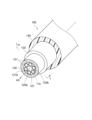
- FIG. 1 is a diagram illustrating the structure of an anti-resonant hollow-core fiber of the present disclosure.
- FIG. 2 is a diagram for explaining the cross-sectional structure of a main portion of the anti-resonant hollow-core fiber of the present disclosure together with the cross-sectional structure of the corresponding main portion of a photonic crystal hollow-core fiber of a comparative example.
- FIG. 3 is a diagram for explaining the calculation of the area ratio in the cross section of the anti-resonant hollow-core fiber of the present disclosure.
- FIG. 4 is a diagram for explaining the drawing step in the manufacturing method of the antiresonant hollow-core fiber of the present disclosure.
- FIG. 5 is a diagram for explaining the gas filling step in the manufacturing method of the anti-resonant hollow-core fiber of the present disclosure.
- FIG. 6 is a table showing the molecular diameter dependence of the diffusion coefficient of various gases that are candidates for the filling gas.
- FIG. 8 is a table showing the calculation results of the penetration time from the start to the completion of gas filling for CF4, one of the gases listed in FIG. 6 , into various glass pipes having different pipe inner diameters D and pipe lengths L of 25,000 m.
- FIG. 9 is a diagram showing the structure of an experimental system for obtaining the calculation results shown in FIGS. 7 and 8, and a graph showing the calculation results.
- FIG. 10 is a graph illustrating the temperature dependence of the penetration time
- the inventors have studied the above-mentioned conventional techniques and found the following problems. That is, the above-mentioned conventional techniques could not avoid the intrusion of gas from the outside into the hollow core fiber, the loss of the gas filled in the holes of the hollow core fiber due to diffusion, or the intrusion of the gas filled in the holes of the hollow core fiber into the glass. Therefore, the above-mentioned conventional techniques had a problem that the transmission loss changes over time due to the refractive index in the holes filled with gas and the reaction between the invaded gas and the glass surface. In addition, the above-mentioned conventional techniques were premised on the use of nonlinear optical effects and optical absorption, and required a huge manufacturing time, so that gas was not actively filled into the long fiber.
- the present disclosure has been made to solve the problems described above, and aims to provide an anti-resonant hollow-core fiber having a structure that enables longer lengths and more stable transmission losses compared to conventional techniques.
- the anti-resonant hollow-core fiber of the present disclosure enables longer lengths and more stable transmission losses compared to conventional techniques.
- An anti-resonant hollow-core fiber includes an outer cladding having a pipe shape and a plurality of inner cladding elements each having a pipe shape.
- the pipe shape of the outer cladding extends along the fiber central axis.
- the inner cladding elements are disposed in the outer cladding so as to surround a space that becomes a core region while being in contact with an inner wall surface of the outer cladding.
- an inner region surrounded by the inner wall surface of the outer cladding, except for a partial region occupied by the inner cladding elements including the inner spaces of the inner cladding elements, is filled with a gas having an optical absorptance lower than H 2 (hydrogen) and a diffusion coefficient lower than Ne (neon) in a wavelength band of 1 ⁇ m or more and 2 ⁇ m or less.
- the hollow optical waveguide region serving as the core region is filled with a gas having an optical absorptance lower than H2 and a diffusion coefficient smaller than Ne in the wavelength band of 1 ⁇ m or more and 2 ⁇ m or less.
- a gas having an optical absorptance lower than H2 and a diffusion coefficient smaller than Ne in the wavelength band of 1 ⁇ m or more and 2 ⁇ m or less suppresses the change in transmission loss over time compared to the conventional technology.
- gas was not actively filled into the long fiber.
- the anti-resonant hollow core fiber of the present disclosure it is easy to secure the gas-filled space serving as the hollow optical waveguide region, and a gas having an optical absorptance lower than H2 and a diffusion coefficient smaller than Ne is selectively filled into the fiber, so that a stable fiber space in which the change in transmission loss over time is suppressed can be obtained.
- the fiber space can be made longer by 1 km or more.
- the effect of suppressing deformation of the fiber due to bending or lateral pressure is also expected.
- the length may be 1 km or more.
- the anti-resonant hollow-core fiber can be made longer.
- the ratio of the total cross-sectional area of the multiple inner cladding elements to the cross-sectional area of the internal region may be 0.55 or more as the area ratio of the cross-section of the anti-resonant hollow core fiber. In this case, sufficient gas filling space is ensured. As a result, it is possible to shorten the gas filling time and to lengthen the anti-resonant hollow core fiber.
- the number of multiple inner cladding elements may be 3 to 6 inclusive. If three or more inner cladding elements are arranged in the outer cladding to surround the core region, an optical confinement effect is achieved. In addition, by limiting the number of inner cladding elements to 6 or less, the degree of freedom in fiber design can be improved to ensure sufficient gas filling space while satisfying the above area ratio.
- the diameter of the inner region may be 80 ⁇ m or more. If the diameter of the inner region is 80 ⁇ m or more, the gas filling time is shortened, and efficient manufacturing is possible.
- the gas filled in the anti-resonant hollow core fiber may include at least one of Ar (argon), Kr (krypton), Xe (xenon), N 2 (nitrogen), O 2 (oxygen), CF 4 (tetrafluoromethane), C 2 F 6 (hexafluoroethane), CCl 2 F 2 (dichlorodifluoromethane), and CClF 3 (chlorotrifluoromethane). That is, the inner region of the outer cladding corresponding to the inner region of the anti-resonant hollow core fiber may be filled with one type of gas such as Ar listed here, or multiple types of gases may coexist in the inner region.
- the transmission loss is stabilized compared to the conventional case.
- different gas composition distributions can be formed along the longitudinal direction of the anti-resonant hollow core fiber, and improvement of transmission characteristics utilizing refractive index changes along the longitudinal direction can be expected.
- the pressure of the gas filled in the anti-resonant hollow-core fiber may be greater than 0.101 MPa and less than 70 MPa at a temperature of 25 degrees Celsius. Stable transmission characteristics can be maintained with suppressed changes in transmission loss over time.
- FIG. 1 is a diagram showing the structure of an antiresonant hollow core fiber of the present disclosure.
- FIG. 2 is a diagram for explaining the cross-sectional structure of the main part of the antiresonant hollow core fiber of the present disclosure together with the cross-sectional structure of the corresponding main part of a photonic crystal hollow core fiber of a comparative example (indicated as "cross-sectional structure" in FIG. 2).
- the upper part of FIG. 2 (indicated as "antiresonant type” in FIG. 2) shows a cross-sectional view of the main part of the antiresonant hollow core fiber along line I-I shown in FIG. 1.
- the lower part of FIG. 2 shows a cross-sectional view of the main part of a photonic crystal hollow core fiber, as a comparative example, corresponding to the cross section along line I-I shown in FIG. 1.
- the anti-resonant hollow core fiber 100 of the present disclosure comprises an outer cladding 120, a plurality of inner cladding elements 121, a jacket layer 130, and a resin coating 140.
- the outer cladding 120 functions as an optical cladding and has a pipe shape extending along the fiber central axis AX.
- the inner region 120b surrounded by the inner wall surface 120a of the outer cladding 120 corresponds to the inner region of the anti-resonant hollow core fiber 100, and the inner region 120b is provided with a plurality of inner cladding elements 121 functioning as a trench layer.
- These inner cladding elements 121 are arranged to surround a space that becomes the core region 110 that functions as a hollow optical waveguide region, with all of the inner cladding elements 121 in contact with the inner wall surface 120a of the outer cladding 120.
- the space that becomes the core region 110 extends along the fiber central axis AX.
- the outer cladding 120 is surrounded by a jacket layer 130 that becomes a physical cladding. Furthermore, a resin coating 140 is provided on the outer periphery of the jacket layer 130.
- the inner region 120b surrounded by the inner wall surface 120a of the outer cladding 120, excluding the partial region occupied by the inner cladding elements 121 including the inner space 121b of the inner cladding elements, is filled with a specific gas.
- this region filled with gas is called a gas-filled region, and the filled gas is called a filling gas.
- This filling gas has a light absorption rate lower than H2 and a diffusion coefficient smaller than Ne in the wavelength band of 1 ⁇ m or more and 2 ⁇ m or less.
- This filling gas is selected from, for example, rare gas, general gas, halogenated carbon, etc.
- the rare gas may be any of Ar, Kr, and Xe.
- the general gas may be any of N2 and O2 .
- the carbon halide may be any one of CF 4 , C 2 F 6 , CCl 2 F 2 and CClF 3 .
- the photonic crystal hollow-core fiber shown in the lower part of Figure 2 as a comparative example has a common cladding 220, in which a large number of air holes 221 are arranged so as to surround a hollow optical waveguide region that becomes the core region 210.
- the large number of air holes 221 are arranged so as to form a periodic structure on the order of wavelength. Light is confined within the core region 210 by the photonic band gap caused by this periodic structure.
- the gas-fillable space of the antiresonant hollow core fiber 100 shown in the upper part of Figure 2 is the gas-filled region described above.
- the gas-fillable space of the photonic crystal hollow core fiber shown in the lower part of Figure 2 is only the core region 210 surrounded by a large number of holes 221 arranged inside the common cladding 220.
- This difference in cross-sectional area manifests itself as a difference in the penetration time from the start to the completion of gas filling, which will be described later.
- Figure 3 is a diagram for explaining the calculation of the area ratio in the cross section of the antiresonant hollow-core fiber 100 of the present disclosure (marked “Area Ratio Calculation” in Figure 3).
- the upper part of Figure 3 (marked “Cross-Section Model” in Figure 3) shows a cross-section model equivalent to the cross section of the antiresonant hollow-core fiber 100 shown in the upper part of Figure 2.
- the lower part of Figure 3 (marked “Enlarged View” in Figure 3) is an enlarged view conceptually showing the actual contact state between the outer cladding 120 and one of the inner cladding elements 121.
- r1 is the radius of the inner region 120b of the outer cladding 120. That is, the distance from the central axis AX to the inner wall surface 120a of the outer cladding 120 is r1.
- r2 is the radius of the inner cladding element 121 from the center 121a to the outer peripheral surface.
- the inner cladding element 121 is embedded in the inner wall surface 120a of the outer cladding 120 as shown in the lower part of FIG. 3. Therefore, in the calculation of the area ratio, r3 is used as a correction value.
- d is the distance between the adjacent inner cladding elements 121.
- ⁇ is the angle between the reference line set on the fiber cross section and the line segment connecting the fiber central axis AX and the center 121a of the inner cladding element 121.
- the correction value r3 of the radius r2 of the inner cladding element 121 is calculated by the formula "r1/(1+1/sin( ⁇ /n))-d/2".
- n is the number of inner cladding elements 121. Therefore, the ratio of the total cross-sectional area of the inner cladding elements 121 to the cross-sectional area of the inner region 120b of the outer cladding 120 (hereinafter referred to as the "area ratio") is given by n x (r3/r1) 2 .
- the radius r1 of the inner region 120b of the outer cladding 120 is fixed at 40 ⁇ m, and the distance d between the inner cladding elements 121 is fixed at 2 ⁇ m.
- the radius of each inner cladding element 121 given by the correction value r3 becomes smaller.
- the area ratio also becomes smaller.
- the correction value r3 of the radius r2 and the radius ratio: r3/r1 are 17.6 ⁇ m and 0.44, respectively, and the area ratio: n ⁇ (r3/r1) 2 is 0.58.
- the inner cladding elements 121 do not function as a trench layer, so three or more inner cladding elements 121 are required.
- the number of inner cladding elements 121 may be 6 or less, and the above area ratio: n ⁇ (r3/r1) 2 may be 0.55 or more.
- the above radii required for calculating the area ratio can be measured by microscopic observation of the end face.
- the number of inner cladding elements 121 may be 3 or more and 6 or less, so the above area ratio may be 0.57 or more and 0.61 or less.
- the above area ratio may be 0.61 or more.
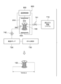
- Figure 4 is a diagram for explaining the drawing process, which corresponds to the first half of the manufacturing method of the antiresonant hollow core fiber 100 of the present disclosure.
- Figure 5 is a diagram for explaining the gas filling process, which corresponds to the second half of the manufacturing method of the antiresonant hollow core fiber 100 of the present disclosure.
- the drawing device shown in FIG. 4 is equipped with a pressure device 300 that applies pressure to the inside of the optical fiber preform 10 to be drawn in order to carry out the first half of the process, a heater 400 that heats one end of the optical fiber preform 10, a resin application device 500 that applies resin to the surface of the hollow glass fiber pulled out from the optical fiber preform 10, a winding device 600 that winds up the fiber intermediate member 150, and a roller 610 that adjusts the traveling direction of the fiber intermediate member 150.
- the optical fiber preform 10 is composed of an outer cladding portion 12 that has a pipe shape and becomes the outer cladding 120 after drawing, a plurality of inner cladding portions 12b that have a pipe shape and become inner cladding elements 121 after drawing, and a jacket portion 13 that becomes the jacket layer 130 after drawing.
- the plurality of inner cladding portions 12b are arranged so as to surround the center of the outer cladding portion 12 while each of them is in contact with the inner wall surface 12a.
- a jacket portion 13 is provided on the outer periphery of the outer cladding 120.
- the end of the optical fiber preform 10 is heated and softened by the heater 400, and the drum of the winding device 600 rotates in the direction indicated by the arrow S, so that a hollow glass fiber is drawn out from the end of the optical fiber preform 10.
- the pressure control gas or air is supplied by the pressurizing device 300 to the internal region of the outer cladding portion 12 and the internal region of each of the multiple inner cladding portions 12b, and these internal regions are in a pressurized state so as not to deform the pipe shape.
- Resin is applied to the surface of the drawn glass fiber by the resin application device 500, and the fiber intermediate member 150 is obtained.
- the internal region of the part after drawing corresponding to the outer cladding 120 and the internal region of the part after drawing corresponding to each of the multiple inner cladding elements 121 are in a hollow state.
- the obtained fiber intermediate member 150 is finally wound up on the drum of the winding device 600 via the roller 610.
- the fiber intermediate member 150 obtained by the drawing device having the above-mentioned structure is set in the device for performing the gas filling process shown in FIG. 5, and the latter half of the process is performed. That is, the device shown in FIG. 5 is equipped with a high-pressure gas supply system 710, a vacuum pump 720, and a gas analyzer 730. One end face of the fiber intermediate member 150 is connected to the high-pressure gas supply system 710 via an on-off valve 741. When the filling gas is supplied from the high-pressure gas supply system 710 to one end face of the fiber intermediate member 150 via the on-off valve 741, the filling gas is supplied to the gas filling area.
- the internal space 121b of the part corresponding to the multiple inner cladding elements 121 is in a vacuum or reduced pressure state, so the filling gas does not enter the part corresponding to these multiple inner cladding elements 121.
- the cross-sectional area of the internal space 121b in the portion corresponding to the multiple inner cladding elements 121 is small, even if gas is filled into the internal space 121b in the portion corresponding to the multiple inner cladding elements 121, the filling of the gas will not be completed within the time it takes to fill the gas filling region with gas.
- a vacuum pump 720 is connected to the other end face of the fiber intermediate member 150 via an on-off valve 742, and the vacuum pump 720 exhausts the residual gas in the internal region of the fiber intermediate member 150, i.e., the region corresponding to the internal region 120b of the outer cladding 120.
- the type of gas exhausted by the vacuum pump 720 is analyzed by a gas analyzer 730. When the gas analyzer 730 detects the filling gas, it can be confirmed that the gas filling is completed and the residual gas has been replaced by the filling gas in the internal region of the fiber intermediate member 150 corresponding to the internal region 120b of the outer cladding 120.
- the gas pressure at the time of sealing is maintained.
- the pressure of the gas filled in the anti-resonant hollow core fiber 100 at the time of sealing is greater than 0.101 MPa and less than 70 MPa at a temperature of 25 degrees Celsius.
- the pressure of the gas being filled can be measured by a pressure gauge provided in the high-pressure gas supply system 710.
- the type and pressure of the gas filled in the anti-resonant hollow-core fiber 100 after filling can be measured by reconnecting the anti-resonant hollow-core fiber 100 to the gas analyzer 730 and the high-pressure gas supply system 710.
- the type and pressure of the gas filled in the anti-resonant hollow-core fiber 100 after filling can also be estimated from the area intensity or peak intensity of the spectrum obtained from spectroscopic measurements such as Raman spectroscopy or stimulated Raman scattering.
- gas filling may be performed with the fiber intermediate member 150 housed in a thermostatic chamber 800 whose interior is maintained at a constant temperature.
- the thermostatic chamber 800 includes a housing 810 that houses the fiber intermediate member 150, a cooling source 820, a heating source 830, a temperature sensor 840, and a temperature control unit 850.
- the temperature control unit 850 controls the cooling source 820 or the heating source 830 while monitoring the internal temperature of the housing 810 with the temperature sensor 840 in order to maintain the internal temperature of the housing 810 at a desired set temperature.
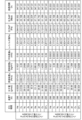
- FIG. 6 is a table showing the molecular diameter dependence of the diffusion coefficient of various gases that are candidates for the filling gas applicable to the anti-resonant hollow-core fiber 100 of the present disclosure.
- the table in FIG. 6 shows the molecular diameter (nm), diffusion coefficient ( cm2 /s), and activation energy (kJ/mol) showing the temperature dependence of the diffusion coefficient for various gases. Note that the diffusion coefficient at a temperature of 25°C is calculated from the known values of the diffusion coefficient and activation energy at a temperature of 1000°C.
- the diffusion coefficients of Ar, Kr, and Xe in rare gases are less than 1 ⁇ 10 ⁇ 20 cm 2 /s, which are all smaller than the diffusion coefficient of Ne, and the light absorption rate is also lower than H 2 in the wavelength range of 1 ⁇ m or more and 2 ⁇ m or less. Therefore, among the rare gas group, Ar, Kr, and Xe are suitable as filling gases for the anti-resonant hollow core fiber 100 of the present disclosure.
- a diffusion coefficient value of less than 1 ⁇ 10 ⁇ 20 cm 2 /s is a value that results in a diffusion distance of 0.1 ⁇ m or less over 15 years.
- He and Ne have large diffusion coefficients and are therefore not suitable as filling gases.
- the diffusion coefficients of N 2 and O 2 are less than 1 ⁇ 10 ⁇ 20 cm 2 /s, which are all smaller than the diffusion coefficient of Ne, and the light absorption rate is also lower than H 2 . Therefore, among the general gases, N 2 and O 2 are suitable for filling gas.
- the diffusion coefficients of H 2 and O 2 are smaller than that of Ne, they are not suitable for filling gas because light absorption occurs in the wavelength band of 1 ⁇ m or more and 2 ⁇ m or less.
- the diffusion coefficients of CF 4 , CCl 2 F 2 , and CClF 3 are less than 1 ⁇ 10 ⁇ 20 cm 2 /s, which are all smaller than the diffusion coefficient of Ne and have a lower light absorption rate than H 2. Therefore, any of the gases listed in the table of FIG. 6 are suitable for filling gas. As examples of other gases, the diffusion coefficients of CH 4 , CO 2 , CO, and C 2 H 4 are also less than 1 ⁇ 10 ⁇ 20 cm 2 /s. However, any of these gases have a higher light absorption rate than H 2 in the wavelength band of 1 ⁇ m or more and 2 ⁇ m or less, so they are not suitable for filling gas.
- C 2 F 6 which is a carbon halide, also has a diffusion coefficient of less than 1 ⁇ 10 ⁇ 20 cm 2 /s and a lower optical absorptivity than H 2 , and is therefore suitable as a filling gas.
- H 2 , He, Ne, and the like have small molecular diameters and diffuse in glass, and therefore may depart in the radial direction of the hollow core fiber. Therefore, these gases are not suitable as filling gases for the anti-resonant hollow core fiber 100 of the present disclosure.
- CH 4 , C 2 H 6 , CO 2 , and the like cause optical absorption due to vibration of C—H bonds and C—O bonds. Therefore, they increase the transmission loss and are not suitable as filling gases.
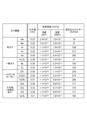
- Fig. 7 is a table showing the calculation results of the penetration time from the start to the completion of gas filling into various glass pipes having different pipe inner diameters D and pipe lengths L of 25,000 m, for several kinds of gases among the various gases listed in Fig. 6.
- the upper part of the table shown in Fig. 7 shows the calculation results of the penetration time from the start to the completion of gas filling into a glass pipe having a pipe inner diameter D of 8.0 x 10 -5 m and a pipe length L of 25,000 m.
- FIG. 7 shows the calculation results of the penetration time from the start to the completion of gas filling into a glass pipe having a pipe inner diameter D of 1.0 x 10 -5 m and a pipe length of 25,000 m.
- FIG. 8 is a table showing the calculation results of the permeation time from the start to the completion of gas filling for various glass pipes having different pipe inner diameters D and a pipe length L of 25,000 m for CF4 among the various gases listed in FIG. 6.
- FIG. 9 is a diagram showing the structure of an experimental system for obtaining the calculation results shown in FIG. 7 and FIG. 8, and a graph showing the calculation results (indicated as "experimental system and calculation results" in FIG. 9). The upper part of FIG. 9 (indicated as "experimental system” in FIG.
- FIG. 9 shows a schematic structure of a glass pipe prepared as an experimental fiber model.
- the middle part of FIG. 9 shows the relationship between the fluid viscosity ⁇ (Pa ⁇ s) and the pressure ⁇ P (MPa) of the gases listed in the upper part of the table shown in FIG. 7.
- the lower part of FIG. 9 shows the relationship between the pipe inner diameter D (m) and the permeation time (h) for CF4 based on the table shown in FIG. 8.
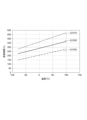
- FIG. 10 is a graph for explaining the temperature dependence of the penetration time for Ar, N 2 , and CF 4 among the gases listed in FIGS.
- a glass pipe with a single pore as shown in the upper part of Figure 9 is assumed as the experimental fiber model.
- This glass pipe has a circular cross section, a pipe inner diameter D, and a pipe length L.
- the pressure loss when a fluid such as a gas is passed through this glass pipe is expressed by the following formula (1).
- the condition of the following formula (2) holds.
- ⁇ is the friction coefficient of the glass pipe against the gas
- L is the pipe length (m)
- D is the pipe inner diameter (m)
- ⁇ is the fluid density (kg/m 3 );
- u is the average flow velocity (m/s);
- ⁇ is the fluid viscosity; and
- Re is the Reynolds number.
- the table shown in FIG . 8 shows the values of the pipe inner diameter D (m), temperature T (K), molecular weight (g/mol), fluid viscosity ⁇ (Pa ⁇ s), fluid density ⁇ (kg/m 3 ), average flow velocity (m/s), Reynolds number Re, pressure ⁇ P (Pa), pressure ⁇ P (MPa), and permeation time (h) for CF 4 as the target gas.
- the graph shown in the lower part of FIG. 9 there is also a correlation between the pipe inner diameter D (m) and the permeation time (h). This tendency can be inferred for other gases.
- the fluid viscosity ⁇ affects the gas filling speed.
- the fluid viscosity ⁇ varies depending on the type of gas and the temperature of the gas. In particular, the effect of temperature is large, and the lower the temperature, the lower the fluid viscosity ⁇ tends to be. Therefore, cooling the fiber intermediate member 150 in FIG. 5 with a thermostatic bath 800 or the like is effective in reducing the permeation time. Such a time dependency of the permeation time is shown in FIG. 10, and the permeation time is reduced by filling the gas at a low temperature regardless of the type of gas.
- the gas to be filled may be one of the gases listed in Fig. 6 etc., which is filled solely in the internal region of the fiber intermediate member 150, or multiple types of gases may coexist in the internal region of the fiber intermediate member 150.
- the line segment G1010 shows the temperature dependence of the permeation time when Ar is selected as the filling gas
- the line segment G1020 shows the temperature dependence of the permeation time when N2 is selected as the filling gas
- the line segment G1030 shows the temperature dependence of the permeation time when CF4 is selected as the filling gas.
- the pipe sample prepared for the measurement has a structure similar to that of the glass pipe shown in the upper part of FIG. 9, the pipe inner diameter D is 8.0 ⁇ 10 ⁇ 5 m, and the pipe length L is 25,000 m.
- the permeation time when the temperature T is 298 K, i.e., 25° C., is adjusted to facilitate comparison.
- the line segment G1010 showing the temperature characteristics of Ar has various parameters, including the fluid viscosity ⁇ , the fluid density ⁇ , the average flow velocity u, the Reynolds number Re, and the pressure ⁇ P, adjusted so that the permeation time when the temperature T is 25° C. is 385 h.
- the line segment G1020 showing the temperature characteristics of N2 has various parameters adjusted, such as the fluid viscosity ⁇ , so that the permeation time when the temperature T is 25° C. is 305 h.
- the line segment G1030 showing the temperature characteristics of CF4 has various parameters adjusted, such as the fluid viscosity, so that the permeation time when the temperature T is 25° C. is 225 h.
- the slope of the line segment G1010 showing the degree of temperature dependency is larger than the remaining line segments G1020 and G1030. In other words, it can be seen that the temperature dependency of Ar is larger than the temperature dependencies of N2 and CF4 .
- the ratio of the total cross-sectional area of the multiple inner cladding elements 121 to the cross-sectional area of the internal region 120b of the outer cladding 120 is set to 0.55 or more as an area ratio. In this way, in the case of the anti-resonant hollow core fiber 100, a sufficient gas-filled space that becomes the hollow optical waveguide region is secured, and it is possible to actually manufacture a fiber having a length of 1 km or more.
- the diameter of the inner region 120b of the outer cladding 120 may be 80 ⁇ m or more. If the diameter of the inner region 120b is 80 ⁇ m or more, the fiber can be efficiently manufactured even if the fiber length is 1 km or more.
- An anti-resonant hollow-core fiber comprising: the anti-resonant hollow-core fiber has a length of 1 km or more; On a cross section of the outer cladding perpendicular to the central axis of the fiber, a remaining region of the inner cladding surrounded by the inner wall surface of the outer cladding, excluding a partial region occupied by the plurality of inner cladding elements, is filled with a gas having an optical absorptance lower than that of H2 and a diffusion coefficient lower than that of Ne in a wavelength band of 1 ⁇ m or more and 2 ⁇ m or less.
- Antiresonant hollow-core fiber On a cross section of the outer cladding perpendicular to the central axis of the fiber, a remaining region of the inner cladding surrounded by the inner wall surface of the outer cladding, excluding a partial region occupied by the plurality of inner cladding elements, is filled with a gas having an optical absorptance lower than that of H2 and a
Landscapes
- Physics & Mathematics (AREA)
- General Physics & Mathematics (AREA)
- Optics & Photonics (AREA)
- Optical Fibers, Optical Fiber Cores, And Optical Fiber Bundles (AREA)
- Manufacture, Treatment Of Glass Fibers (AREA)
Priority Applications (4)
| Application Number | Priority Date | Filing Date | Title |
|---|---|---|---|
| JP2024550026A JPWO2024070658A1 (https=) | 2022-09-30 | 2023-09-12 | |
| US19/114,118 US20260098997A1 (en) | 2022-09-30 | 2023-09-12 | Anti-resonant hollow-core fiber |
| CN202380062829.1A CN119968585A (zh) | 2022-09-30 | 2023-09-12 | 反谐振空芯光纤 |
| EP23871893.6A EP4597179A4 (en) | 2022-09-30 | 2023-09-12 | ANTI-RESONANCE HOLLOW CORE FIBER |
Applications Claiming Priority (2)
| Application Number | Priority Date | Filing Date | Title |
|---|---|---|---|
| JP2022157789 | 2022-09-30 | ||
| JP2022-157789 | 2022-09-30 |
Publications (1)
| Publication Number | Publication Date |
|---|---|
| WO2024070658A1 true WO2024070658A1 (ja) | 2024-04-04 |
Family
ID=90477478
Family Applications (1)
| Application Number | Title | Priority Date | Filing Date |
|---|---|---|---|
| PCT/JP2023/033160 Ceased WO2024070658A1 (ja) | 2022-09-30 | 2023-09-12 | 反共振中空コアファイバ |
Country Status (5)
| Country | Link |
|---|---|
| US (1) | US20260098997A1 (https=) |
| EP (1) | EP4597179A4 (https=) |
| JP (1) | JPWO2024070658A1 (https=) |
| CN (1) | CN119968585A (https=) |
| WO (1) | WO2024070658A1 (https=) |
Citations (2)
| Publication number | Priority date | Publication date | Assignee | Title |
|---|---|---|---|---|
| WO2022048847A1 (en) * | 2020-09-03 | 2022-03-10 | Asml Netherlands B.V. | Hollow-core photonic crystal fiber based broadband radiation generator |
| JP2022157789A (ja) | 2021-03-31 | 2022-10-14 | 本田技研工業株式会社 | 複合動力システム |
Family Cites Families (1)
| Publication number | Priority date | Publication date | Assignee | Title |
|---|---|---|---|---|
| GB202014418D0 (en) * | 2020-09-14 | 2020-10-28 | Univ Southampton | Hollow core optical waveguides and methods for modification thereof |
-
2023
- 2023-09-12 JP JP2024550026A patent/JPWO2024070658A1/ja active Pending
- 2023-09-12 CN CN202380062829.1A patent/CN119968585A/zh active Pending
- 2023-09-12 US US19/114,118 patent/US20260098997A1/en active Pending
- 2023-09-12 WO PCT/JP2023/033160 patent/WO2024070658A1/ja not_active Ceased
- 2023-09-12 EP EP23871893.6A patent/EP4597179A4/en active Pending
Patent Citations (2)
| Publication number | Priority date | Publication date | Assignee | Title |
|---|---|---|---|---|
| WO2022048847A1 (en) * | 2020-09-03 | 2022-03-10 | Asml Netherlands B.V. | Hollow-core photonic crystal fiber based broadband radiation generator |
| JP2022157789A (ja) | 2021-03-31 | 2022-10-14 | 本田技研工業株式会社 | 複合動力システム |
Non-Patent Citations (7)
| Title |
|---|
| GREGORY T. JASION ET AL.: "Fabrication of tubular anti-resonant hollow core fibers: modelling, draw dynamics and process optimization", OPTICS EXPRESS, vol. 27, no. 15, 22 July 2019 (2019-07-22), pages 20567 - 20581, XP055655469, DOI: 10.1364/OE.27.020567 |
| HABIB MD. SELIM; MARKOS CHRISTOS; BANG OLE; BACHE MORTEN: "Generation of multiple VUV dispersive waves using a tapered gas-filled hollow-core anti-resonant fiber", 2017 CONFERENCE ON LASERS AND ELECTRO-OPTICS EUROPE & EUROPEAN QUANTUM ELECTRONICS CONFERENCE (CLEO/EUROPE-EQEC), IEEE, 25 June 2017 (2017-06-25), pages 1 - 1, XP033239470, DOI: 10.1109/CLEOE-EQEC.2017.8086491 * |
| KHOSRAVI R.; HAJATI M.; KACEROVSKA B.; MA P.; LIANG C.; MONFARED YASHAR E.: "Hollow-Core Photonic Crystal Fibers Filled with Noble Gases: He, Ne, Ar, Kr, Xe", 2019 PHOTONICS NORTH (PN), IEEE, 21 May 2019 (2019-05-21), pages 1 - 1, XP033608951, DOI: 10.1109/PN.2019.8819515 * |
| LI WENTONG, CHAN CALVIN CHUN-KIT: "Heterogeneous Gas-filling in Anti-resonant Hollow Core Fibers", 2020 OPTO-ELECTRONICS AND COMMUNICATIONS CONFERENCE (OECC), IEEE, 4 October 2020 (2020-10-04) - 8 October 2020 (2020-10-08), pages 1 - 3, XP093151571, ISBN: 978-1-7281-5445-9, DOI: 10.1109/OECC48412.2020.9273739 * |
| O. H. HECKL ET AL.: "Temporal pulse compression in a xenon-filled Kagome-type hollow-core photonics crystal fiber at high average power", OPTICS EXPRESS, vol. 19, no. 20, 26 September 2011 (2011-09-26), pages 19142 - 19148 |
| See also references of EP4597179A4 |
| ZÜRCH M., SOLLAPUR R., HOFFMANN A., SAUER G., HARTUNG A., KARTASHOV D., SCHMIDT M., SPIELMANN C.: "Octave Broadband Supercontinuum Generation in Gas-Filled Anti-Resonant Hollow-Core Fiber", CONFERENCE ON LASERS AND ELECTRO-OPTICS, OSA, WASHINGTON, D.C., 1 January 2016 (2016-01-01), Washington, D.C. , pages AM4J.2, XP093151576, ISBN: 978-1-943580-11-8, DOI: 10.1364/CLEO_AT.2016.AM4J.2 * |
Also Published As
| Publication number | Publication date |
|---|---|
| CN119968585A (zh) | 2025-05-09 |
| EP4597179A1 (en) | 2025-08-06 |
| US20260098997A1 (en) | 2026-04-09 |
| JPWO2024070658A1 (https=) | 2024-04-04 |
| EP4597179A4 (en) | 2026-01-07 |
Similar Documents
| Publication | Publication Date | Title |
|---|---|---|
| US11947160B2 (en) | Laser system using low-chlorine hollow core optical fiber | |
| JP7789633B2 (ja) | 高温ロード工程による微細構造ファイバの寿命延長および性能改善 | |
| EP1234806B1 (en) | Manufacturing method thereof of an optical fibre | |
| US7450813B2 (en) | Rare earth doped and large effective area optical fibers for fiber lasers and amplifiers | |
| US7526166B2 (en) | High numerical aperture fiber | |
| JP2025000771A (ja) | フォトニック結晶ファイバ、その作製方法、及びスーパーコンティニューム光源 | |
| DK2140294T3 (en) | Optical fiber article to handling of major energy and manufacturing method or use thereof | |
| US20090238215A1 (en) | Method Of Inducing Refractive Index Structures In A Micro-Structured Fiber, A Micro-Structured Fiber And An Article | |
| US7221838B2 (en) | Optical fibers with reduced splice loss and methods for making same | |
| US20090052476A1 (en) | Optical fiber for an optical fiber laser, method for fabricating the same, and optical fiber laser | |
| WO2024070658A1 (ja) | 反共振中空コアファイバ | |
| US20040062499A1 (en) | Method of fabricating an optical fiber with microstructures | |
| US20260022053A1 (en) | Method for processing hollow core optical fibres | |
| JP5329347B2 (ja) | 紫外線伝送用光ファイバ及びその製造方法 | |
| JP3872796B2 (ja) | フォトニッククリスタルファイバの製造方法 | |
| JPWO2024070658A5 (https=) |
Legal Events
| Date | Code | Title | Description |
|---|---|---|---|
| 121 | Ep: the epo has been informed by wipo that ep was designated in this application |
Ref document number: 23871893 Country of ref document: EP Kind code of ref document: A1 |
|
| WWE | Wipo information: entry into national phase |
Ref document number: 2024550026 Country of ref document: JP |
|
| WWE | Wipo information: entry into national phase |
Ref document number: 202380062829.1 Country of ref document: CN |
|
| WWE | Wipo information: entry into national phase |
Ref document number: 2023871893 Country of ref document: EP |
|
| NENP | Non-entry into the national phase |
Ref country code: DE |
|
| ENP | Entry into the national phase |
Ref document number: 2023871893 Country of ref document: EP Effective date: 20250430 |
|
| WWP | Wipo information: published in national office |
Ref document number: 202380062829.1 Country of ref document: CN |
|
| WWP | Wipo information: published in national office |
Ref document number: 2023871893 Country of ref document: EP |