WO2024070658A1 - Antiresonance hollow-core fiber - Google Patents
Antiresonance hollow-core fiber Download PDFInfo
- Publication number
- WO2024070658A1 WO2024070658A1 PCT/JP2023/033160 JP2023033160W WO2024070658A1 WO 2024070658 A1 WO2024070658 A1 WO 2024070658A1 JP 2023033160 W JP2023033160 W JP 2023033160W WO 2024070658 A1 WO2024070658 A1 WO 2024070658A1
- Authority
- WO
- WIPO (PCT)
- Prior art keywords
- gas
- fiber
- core fiber
- region
- hollow
- Prior art date
Links
- 239000000835 fiber Substances 0.000 title claims abstract description 130
- 238000005253 cladding Methods 0.000 claims abstract description 115
- 238000009792 diffusion process Methods 0.000 claims abstract description 29
- 230000003287 optical effect Effects 0.000 claims abstract description 22
- TXEYQDLBPFQVAA-UHFFFAOYSA-N tetrafluoromethane Chemical compound FC(F)(F)F TXEYQDLBPFQVAA-UHFFFAOYSA-N 0.000 claims description 8
- 229910052786 argon Inorganic materials 0.000 claims description 7
- 229910052743 krypton Inorganic materials 0.000 claims description 6
- 229910052724 xenon Inorganic materials 0.000 claims description 6
- AFYPFACVUDMOHA-UHFFFAOYSA-N chlorotrifluoromethane Chemical compound FC(F)(F)Cl AFYPFACVUDMOHA-UHFFFAOYSA-N 0.000 claims description 2
- PXBRQCKWGAHEHS-UHFFFAOYSA-N dichlorodifluoromethane Chemical compound FC(F)(Cl)Cl PXBRQCKWGAHEHS-UHFFFAOYSA-N 0.000 claims description 2
- 235000019404 dichlorodifluoromethane Nutrition 0.000 claims description 2
- WMIYKQLTONQJES-UHFFFAOYSA-N hexafluoroethane Chemical compound FC(F)(F)C(F)(F)F WMIYKQLTONQJES-UHFFFAOYSA-N 0.000 claims description 2
- 238000010521 absorption reaction Methods 0.000 abstract description 4
- 239000007789 gas Substances 0.000 description 148
- 238000004364 calculation method Methods 0.000 description 19
- 239000011521 glass Substances 0.000 description 19
- 239000012530 fluid Substances 0.000 description 17
- 230000005540 biological transmission Effects 0.000 description 13
- 238000010586 diagram Methods 0.000 description 12
- 239000004038 photonic crystal Substances 0.000 description 12
- 230000035515 penetration Effects 0.000 description 10
- 238000004519 manufacturing process Methods 0.000 description 9
- 239000011347 resin Substances 0.000 description 8
- 229920005989 resin Polymers 0.000 description 8
- 239000013307 optical fiber Substances 0.000 description 7
- 238000007796 conventional method Methods 0.000 description 6
- 230000031700 light absorption Effects 0.000 description 6
- 230000000052 comparative effect Effects 0.000 description 5
- 238000001816 cooling Methods 0.000 description 4
- 238000012937 correction Methods 0.000 description 4
- 230000000694 effects Effects 0.000 description 4
- 238000010438 heat treatment Methods 0.000 description 4
- 238000004804 winding Methods 0.000 description 4
- 229910052799 carbon Inorganic materials 0.000 description 3
- 230000008859 change Effects 0.000 description 3
- KYKAJFCTULSVSH-UHFFFAOYSA-N chloro(fluoro)methane Chemical compound F[C]Cl KYKAJFCTULSVSH-UHFFFAOYSA-N 0.000 description 3
- 239000011248 coating agent Substances 0.000 description 3
- 238000000576 coating method Methods 0.000 description 3
- 238000005429 filling process Methods 0.000 description 3
- 239000003365 glass fiber Substances 0.000 description 3
- 229910052734 helium Inorganic materials 0.000 description 3
- 238000005259 measurement Methods 0.000 description 3
- 238000000034 method Methods 0.000 description 3
- 229910052754 neon Inorganic materials 0.000 description 3
- 230000000737 periodic effect Effects 0.000 description 3
- 230000008569 process Effects 0.000 description 3
- XKRFYHLGVUSROY-UHFFFAOYSA-N Argon Chemical compound [Ar] XKRFYHLGVUSROY-UHFFFAOYSA-N 0.000 description 2
- IJGRMHOSHXDMSA-UHFFFAOYSA-N Atomic nitrogen Chemical compound N#N IJGRMHOSHXDMSA-UHFFFAOYSA-N 0.000 description 2
- 238000001069 Raman spectroscopy Methods 0.000 description 2
- 230000004913 activation Effects 0.000 description 2
- -1 carbon halide Chemical class 0.000 description 2
- 238000009826 distribution Methods 0.000 description 2
- 239000000945 filler Substances 0.000 description 2
- 229910052739 hydrogen Inorganic materials 0.000 description 2
- 230000006872 improvement Effects 0.000 description 2
- 239000000203 mixture Substances 0.000 description 2
- 229910052757 nitrogen Inorganic materials 0.000 description 2
- 238000007789 sealing Methods 0.000 description 2
- 239000004338 Dichlorodifluoromethane Substances 0.000 description 1
- UFHFLCQGNIYNRP-UHFFFAOYSA-N Hydrogen Chemical compound [H][H] UFHFLCQGNIYNRP-UHFFFAOYSA-N 0.000 description 1
- QVGXLLKOCUKJST-UHFFFAOYSA-N atomic oxygen Chemical compound [O] QVGXLLKOCUKJST-UHFFFAOYSA-N 0.000 description 1
- 238000005452 bending Methods 0.000 description 1
- 150000001721 carbon Chemical class 0.000 description 1
- 238000006243 chemical reaction Methods 0.000 description 1
- 238000013461 design Methods 0.000 description 1
- 238000005516 engineering process Methods 0.000 description 1
- 239000001257 hydrogen Substances 0.000 description 1
- 238000002347 injection Methods 0.000 description 1
- 239000007924 injection Substances 0.000 description 1
- DNNSSWSSYDEUBZ-UHFFFAOYSA-N krypton atom Chemical compound [Kr] DNNSSWSSYDEUBZ-UHFFFAOYSA-N 0.000 description 1
- 239000000463 material Substances 0.000 description 1
- 238000012986 modification Methods 0.000 description 1
- 230000004048 modification Effects 0.000 description 1
- 238000012544 monitoring process Methods 0.000 description 1
- GKAOGPIIYCISHV-UHFFFAOYSA-N neon atom Chemical compound [Ne] GKAOGPIIYCISHV-UHFFFAOYSA-N 0.000 description 1
- 239000001301 oxygen Substances 0.000 description 1
- 229910052760 oxygen Inorganic materials 0.000 description 1
- 230000002093 peripheral effect Effects 0.000 description 1
- 239000011148 porous material Substances 0.000 description 1
- 238000001228 spectrum Methods 0.000 description 1
- 230000006641 stabilisation Effects 0.000 description 1
- 238000011105 stabilization Methods 0.000 description 1
- FHNFHKCVQCLJFQ-UHFFFAOYSA-N xenon atom Chemical compound [Xe] FHNFHKCVQCLJFQ-UHFFFAOYSA-N 0.000 description 1
Images


Classifications
-
- G—PHYSICS
- G02—OPTICS
- G02B—OPTICAL ELEMENTS, SYSTEMS OR APPARATUS
- G02B6/00—Light guides; Structural details of arrangements comprising light guides and other optical elements, e.g. couplings
- G02B6/02—Optical fibres with cladding with or without a coating
- G02B6/032—Optical fibres with cladding with or without a coating with non solid core or cladding
Definitions
- hollow-core fibers examples include photonic crystal hollow-core fiber and anti-resonant hollow-core fiber.
- Hollow-core fibers are used for measuring gas components through spectroscopic measurement. Hollow-core fibers are manufactured by drawing a base material made of a number of bundled pipes while heating it. The holes in the hollow-core fiber obtained by this manufacturing method contain gas for controlling the pressure during drawing, atmosphere, etc.
- a photonic crystal hollow-core fiber is a hollow-core fiber that controls light confinement by utilizing a photonic band gap, as disclosed in, for example, Non-Patent Document 1.
- a large number of holes are arranged in the cladding of the photonic crystal hollow-core fiber so as to form a periodic structure on the order of wavelength.
- the cross-sectional area of the space that becomes the core region surrounded by the large number of holes is small, ranging from several tens of ⁇ m2 to 100 ⁇ m2 . Therefore, the injection of high-pressure gas into the holes is suppressed.
- the inner region of the outer cladding has a continuous cross-sectional structure along the central axis of the fiber.
- the cross-sectional area is several thousand ⁇ m2 . Therefore, it is possible to significantly reduce the time required to inject gas from the fiber end face, as compared with the above-mentioned photonic crystal hollow-core fiber.
- the anti-resonant hollow core fiber of the present disclosure includes an outer cladding having a pipe shape and a plurality of inner cladding elements each having a pipe shape.
- the pipe shape of the outer cladding extends along the fiber central axis.
- the inner cladding elements are arranged to surround a space that becomes a core region while in contact with an inner wall surface of the outer cladding.
- the inner region surrounded by the inner wall surface of the outer cladding, except for a partial region occupied by the inner cladding elements including the inner space of the inner cladding elements, is filled with a gas having an optical absorptance lower than H2 and a diffusion coefficient lower than Ne in a wavelength band of 1 ⁇ m to 2 ⁇ m.
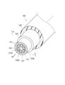
- FIG. 1 is a diagram illustrating the structure of an anti-resonant hollow-core fiber of the present disclosure.
- FIG. 2 is a diagram for explaining the cross-sectional structure of a main portion of the anti-resonant hollow-core fiber of the present disclosure together with the cross-sectional structure of the corresponding main portion of a photonic crystal hollow-core fiber of a comparative example.
- FIG. 3 is a diagram for explaining the calculation of the area ratio in the cross section of the anti-resonant hollow-core fiber of the present disclosure.
- FIG. 4 is a diagram for explaining the drawing step in the manufacturing method of the antiresonant hollow-core fiber of the present disclosure.
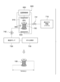
- FIG. 5 is a diagram for explaining the gas filling step in the manufacturing method of the anti-resonant hollow-core fiber of the present disclosure.
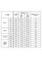
- FIG. 6 is a table showing the molecular diameter dependence of the diffusion coefficient of various gases that are candidates for the filling gas.
- FIG. 8 is a table showing the calculation results of the penetration time from the start to the completion of gas filling for CF4, one of the gases listed in FIG. 6 , into various glass pipes having different pipe inner diameters D and pipe lengths L of 25,000 m.
- FIG. 9 is a diagram showing the structure of an experimental system for obtaining the calculation results shown in FIGS. 7 and 8, and a graph showing the calculation results.
- FIG. 10 is a graph illustrating the temperature dependence of the penetration time
- the inventors have studied the above-mentioned conventional techniques and found the following problems. That is, the above-mentioned conventional techniques could not avoid the intrusion of gas from the outside into the hollow core fiber, the loss of the gas filled in the holes of the hollow core fiber due to diffusion, or the intrusion of the gas filled in the holes of the hollow core fiber into the glass. Therefore, the above-mentioned conventional techniques had a problem that the transmission loss changes over time due to the refractive index in the holes filled with gas and the reaction between the invaded gas and the glass surface. In addition, the above-mentioned conventional techniques were premised on the use of nonlinear optical effects and optical absorption, and required a huge manufacturing time, so that gas was not actively filled into the long fiber.
- the present disclosure has been made to solve the problems described above, and aims to provide an anti-resonant hollow-core fiber having a structure that enables longer lengths and more stable transmission losses compared to conventional techniques.
- the anti-resonant hollow-core fiber of the present disclosure enables longer lengths and more stable transmission losses compared to conventional techniques.
- An anti-resonant hollow-core fiber includes an outer cladding having a pipe shape and a plurality of inner cladding elements each having a pipe shape.
- the pipe shape of the outer cladding extends along the fiber central axis.
- the inner cladding elements are disposed in the outer cladding so as to surround a space that becomes a core region while being in contact with an inner wall surface of the outer cladding.
- an inner region surrounded by the inner wall surface of the outer cladding, except for a partial region occupied by the inner cladding elements including the inner spaces of the inner cladding elements, is filled with a gas having an optical absorptance lower than H 2 (hydrogen) and a diffusion coefficient lower than Ne (neon) in a wavelength band of 1 ⁇ m or more and 2 ⁇ m or less.
- the hollow optical waveguide region serving as the core region is filled with a gas having an optical absorptance lower than H2 and a diffusion coefficient smaller than Ne in the wavelength band of 1 ⁇ m or more and 2 ⁇ m or less.
- a gas having an optical absorptance lower than H2 and a diffusion coefficient smaller than Ne in the wavelength band of 1 ⁇ m or more and 2 ⁇ m or less suppresses the change in transmission loss over time compared to the conventional technology.
- gas was not actively filled into the long fiber.
- the anti-resonant hollow core fiber of the present disclosure it is easy to secure the gas-filled space serving as the hollow optical waveguide region, and a gas having an optical absorptance lower than H2 and a diffusion coefficient smaller than Ne is selectively filled into the fiber, so that a stable fiber space in which the change in transmission loss over time is suppressed can be obtained.
- the fiber space can be made longer by 1 km or more.
- the effect of suppressing deformation of the fiber due to bending or lateral pressure is also expected.
- the length may be 1 km or more.
- the anti-resonant hollow-core fiber can be made longer.
- the ratio of the total cross-sectional area of the multiple inner cladding elements to the cross-sectional area of the internal region may be 0.55 or more as the area ratio of the cross-section of the anti-resonant hollow core fiber. In this case, sufficient gas filling space is ensured. As a result, it is possible to shorten the gas filling time and to lengthen the anti-resonant hollow core fiber.
- the number of multiple inner cladding elements may be 3 to 6 inclusive. If three or more inner cladding elements are arranged in the outer cladding to surround the core region, an optical confinement effect is achieved. In addition, by limiting the number of inner cladding elements to 6 or less, the degree of freedom in fiber design can be improved to ensure sufficient gas filling space while satisfying the above area ratio.
- the diameter of the inner region may be 80 ⁇ m or more. If the diameter of the inner region is 80 ⁇ m or more, the gas filling time is shortened, and efficient manufacturing is possible.
- the gas filled in the anti-resonant hollow core fiber may include at least one of Ar (argon), Kr (krypton), Xe (xenon), N 2 (nitrogen), O 2 (oxygen), CF 4 (tetrafluoromethane), C 2 F 6 (hexafluoroethane), CCl 2 F 2 (dichlorodifluoromethane), and CClF 3 (chlorotrifluoromethane). That is, the inner region of the outer cladding corresponding to the inner region of the anti-resonant hollow core fiber may be filled with one type of gas such as Ar listed here, or multiple types of gases may coexist in the inner region.
- the transmission loss is stabilized compared to the conventional case.
- different gas composition distributions can be formed along the longitudinal direction of the anti-resonant hollow core fiber, and improvement of transmission characteristics utilizing refractive index changes along the longitudinal direction can be expected.
- the pressure of the gas filled in the anti-resonant hollow-core fiber may be greater than 0.101 MPa and less than 70 MPa at a temperature of 25 degrees Celsius. Stable transmission characteristics can be maintained with suppressed changes in transmission loss over time.
- FIG. 1 is a diagram showing the structure of an antiresonant hollow core fiber of the present disclosure.
- FIG. 2 is a diagram for explaining the cross-sectional structure of the main part of the antiresonant hollow core fiber of the present disclosure together with the cross-sectional structure of the corresponding main part of a photonic crystal hollow core fiber of a comparative example (indicated as "cross-sectional structure" in FIG. 2).
- the upper part of FIG. 2 (indicated as "antiresonant type” in FIG. 2) shows a cross-sectional view of the main part of the antiresonant hollow core fiber along line I-I shown in FIG. 1.
- the lower part of FIG. 2 shows a cross-sectional view of the main part of a photonic crystal hollow core fiber, as a comparative example, corresponding to the cross section along line I-I shown in FIG. 1.
- the anti-resonant hollow core fiber 100 of the present disclosure comprises an outer cladding 120, a plurality of inner cladding elements 121, a jacket layer 130, and a resin coating 140.
- the outer cladding 120 functions as an optical cladding and has a pipe shape extending along the fiber central axis AX.
- the inner region 120b surrounded by the inner wall surface 120a of the outer cladding 120 corresponds to the inner region of the anti-resonant hollow core fiber 100, and the inner region 120b is provided with a plurality of inner cladding elements 121 functioning as a trench layer.
- These inner cladding elements 121 are arranged to surround a space that becomes the core region 110 that functions as a hollow optical waveguide region, with all of the inner cladding elements 121 in contact with the inner wall surface 120a of the outer cladding 120.
- the space that becomes the core region 110 extends along the fiber central axis AX.
- the outer cladding 120 is surrounded by a jacket layer 130 that becomes a physical cladding. Furthermore, a resin coating 140 is provided on the outer periphery of the jacket layer 130.
- the inner region 120b surrounded by the inner wall surface 120a of the outer cladding 120, excluding the partial region occupied by the inner cladding elements 121 including the inner space 121b of the inner cladding elements, is filled with a specific gas.
- this region filled with gas is called a gas-filled region, and the filled gas is called a filling gas.
- This filling gas has a light absorption rate lower than H2 and a diffusion coefficient smaller than Ne in the wavelength band of 1 ⁇ m or more and 2 ⁇ m or less.
- This filling gas is selected from, for example, rare gas, general gas, halogenated carbon, etc.
- the rare gas may be any of Ar, Kr, and Xe.
- the general gas may be any of N2 and O2 .
- the carbon halide may be any one of CF 4 , C 2 F 6 , CCl 2 F 2 and CClF 3 .
- the photonic crystal hollow-core fiber shown in the lower part of Figure 2 as a comparative example has a common cladding 220, in which a large number of air holes 221 are arranged so as to surround a hollow optical waveguide region that becomes the core region 210.
- the large number of air holes 221 are arranged so as to form a periodic structure on the order of wavelength. Light is confined within the core region 210 by the photonic band gap caused by this periodic structure.
- the gas-fillable space of the antiresonant hollow core fiber 100 shown in the upper part of Figure 2 is the gas-filled region described above.
- the gas-fillable space of the photonic crystal hollow core fiber shown in the lower part of Figure 2 is only the core region 210 surrounded by a large number of holes 221 arranged inside the common cladding 220.
- This difference in cross-sectional area manifests itself as a difference in the penetration time from the start to the completion of gas filling, which will be described later.
- Figure 3 is a diagram for explaining the calculation of the area ratio in the cross section of the antiresonant hollow-core fiber 100 of the present disclosure (marked “Area Ratio Calculation” in Figure 3).
- the upper part of Figure 3 (marked “Cross-Section Model” in Figure 3) shows a cross-section model equivalent to the cross section of the antiresonant hollow-core fiber 100 shown in the upper part of Figure 2.
- the lower part of Figure 3 (marked “Enlarged View” in Figure 3) is an enlarged view conceptually showing the actual contact state between the outer cladding 120 and one of the inner cladding elements 121.
- r1 is the radius of the inner region 120b of the outer cladding 120. That is, the distance from the central axis AX to the inner wall surface 120a of the outer cladding 120 is r1.
- r2 is the radius of the inner cladding element 121 from the center 121a to the outer peripheral surface.
- the inner cladding element 121 is embedded in the inner wall surface 120a of the outer cladding 120 as shown in the lower part of FIG. 3. Therefore, in the calculation of the area ratio, r3 is used as a correction value.
- d is the distance between the adjacent inner cladding elements 121.
- ⁇ is the angle between the reference line set on the fiber cross section and the line segment connecting the fiber central axis AX and the center 121a of the inner cladding element 121.
- the correction value r3 of the radius r2 of the inner cladding element 121 is calculated by the formula "r1/(1+1/sin( ⁇ /n))-d/2".
- n is the number of inner cladding elements 121. Therefore, the ratio of the total cross-sectional area of the inner cladding elements 121 to the cross-sectional area of the inner region 120b of the outer cladding 120 (hereinafter referred to as the "area ratio") is given by n x (r3/r1) 2 .
- the radius r1 of the inner region 120b of the outer cladding 120 is fixed at 40 ⁇ m, and the distance d between the inner cladding elements 121 is fixed at 2 ⁇ m.
- the radius of each inner cladding element 121 given by the correction value r3 becomes smaller.
- the area ratio also becomes smaller.
- the correction value r3 of the radius r2 and the radius ratio: r3/r1 are 17.6 ⁇ m and 0.44, respectively, and the area ratio: n ⁇ (r3/r1) 2 is 0.58.
- the inner cladding elements 121 do not function as a trench layer, so three or more inner cladding elements 121 are required.
- the number of inner cladding elements 121 may be 6 or less, and the above area ratio: n ⁇ (r3/r1) 2 may be 0.55 or more.
- the above radii required for calculating the area ratio can be measured by microscopic observation of the end face.
- the number of inner cladding elements 121 may be 3 or more and 6 or less, so the above area ratio may be 0.57 or more and 0.61 or less.
- the above area ratio may be 0.61 or more.
- Figure 4 is a diagram for explaining the drawing process, which corresponds to the first half of the manufacturing method of the antiresonant hollow core fiber 100 of the present disclosure.
- Figure 5 is a diagram for explaining the gas filling process, which corresponds to the second half of the manufacturing method of the antiresonant hollow core fiber 100 of the present disclosure.
- the drawing device shown in FIG. 4 is equipped with a pressure device 300 that applies pressure to the inside of the optical fiber preform 10 to be drawn in order to carry out the first half of the process, a heater 400 that heats one end of the optical fiber preform 10, a resin application device 500 that applies resin to the surface of the hollow glass fiber pulled out from the optical fiber preform 10, a winding device 600 that winds up the fiber intermediate member 150, and a roller 610 that adjusts the traveling direction of the fiber intermediate member 150.
- the optical fiber preform 10 is composed of an outer cladding portion 12 that has a pipe shape and becomes the outer cladding 120 after drawing, a plurality of inner cladding portions 12b that have a pipe shape and become inner cladding elements 121 after drawing, and a jacket portion 13 that becomes the jacket layer 130 after drawing.
- the plurality of inner cladding portions 12b are arranged so as to surround the center of the outer cladding portion 12 while each of them is in contact with the inner wall surface 12a.
- a jacket portion 13 is provided on the outer periphery of the outer cladding 120.
- the end of the optical fiber preform 10 is heated and softened by the heater 400, and the drum of the winding device 600 rotates in the direction indicated by the arrow S, so that a hollow glass fiber is drawn out from the end of the optical fiber preform 10.
- the pressure control gas or air is supplied by the pressurizing device 300 to the internal region of the outer cladding portion 12 and the internal region of each of the multiple inner cladding portions 12b, and these internal regions are in a pressurized state so as not to deform the pipe shape.
- Resin is applied to the surface of the drawn glass fiber by the resin application device 500, and the fiber intermediate member 150 is obtained.
- the internal region of the part after drawing corresponding to the outer cladding 120 and the internal region of the part after drawing corresponding to each of the multiple inner cladding elements 121 are in a hollow state.
- the obtained fiber intermediate member 150 is finally wound up on the drum of the winding device 600 via the roller 610.
- the fiber intermediate member 150 obtained by the drawing device having the above-mentioned structure is set in the device for performing the gas filling process shown in FIG. 5, and the latter half of the process is performed. That is, the device shown in FIG. 5 is equipped with a high-pressure gas supply system 710, a vacuum pump 720, and a gas analyzer 730. One end face of the fiber intermediate member 150 is connected to the high-pressure gas supply system 710 via an on-off valve 741. When the filling gas is supplied from the high-pressure gas supply system 710 to one end face of the fiber intermediate member 150 via the on-off valve 741, the filling gas is supplied to the gas filling area.
- the internal space 121b of the part corresponding to the multiple inner cladding elements 121 is in a vacuum or reduced pressure state, so the filling gas does not enter the part corresponding to these multiple inner cladding elements 121.
- the cross-sectional area of the internal space 121b in the portion corresponding to the multiple inner cladding elements 121 is small, even if gas is filled into the internal space 121b in the portion corresponding to the multiple inner cladding elements 121, the filling of the gas will not be completed within the time it takes to fill the gas filling region with gas.
- a vacuum pump 720 is connected to the other end face of the fiber intermediate member 150 via an on-off valve 742, and the vacuum pump 720 exhausts the residual gas in the internal region of the fiber intermediate member 150, i.e., the region corresponding to the internal region 120b of the outer cladding 120.
- the type of gas exhausted by the vacuum pump 720 is analyzed by a gas analyzer 730. When the gas analyzer 730 detects the filling gas, it can be confirmed that the gas filling is completed and the residual gas has been replaced by the filling gas in the internal region of the fiber intermediate member 150 corresponding to the internal region 120b of the outer cladding 120.
- the gas pressure at the time of sealing is maintained.
- the pressure of the gas filled in the anti-resonant hollow core fiber 100 at the time of sealing is greater than 0.101 MPa and less than 70 MPa at a temperature of 25 degrees Celsius.
- the pressure of the gas being filled can be measured by a pressure gauge provided in the high-pressure gas supply system 710.
- the type and pressure of the gas filled in the anti-resonant hollow-core fiber 100 after filling can be measured by reconnecting the anti-resonant hollow-core fiber 100 to the gas analyzer 730 and the high-pressure gas supply system 710.
- the type and pressure of the gas filled in the anti-resonant hollow-core fiber 100 after filling can also be estimated from the area intensity or peak intensity of the spectrum obtained from spectroscopic measurements such as Raman spectroscopy or stimulated Raman scattering.
- gas filling may be performed with the fiber intermediate member 150 housed in a thermostatic chamber 800 whose interior is maintained at a constant temperature.
- the thermostatic chamber 800 includes a housing 810 that houses the fiber intermediate member 150, a cooling source 820, a heating source 830, a temperature sensor 840, and a temperature control unit 850.
- the temperature control unit 850 controls the cooling source 820 or the heating source 830 while monitoring the internal temperature of the housing 810 with the temperature sensor 840 in order to maintain the internal temperature of the housing 810 at a desired set temperature.
- FIG. 6 is a table showing the molecular diameter dependence of the diffusion coefficient of various gases that are candidates for the filling gas applicable to the anti-resonant hollow-core fiber 100 of the present disclosure.
- the table in FIG. 6 shows the molecular diameter (nm), diffusion coefficient ( cm2 /s), and activation energy (kJ/mol) showing the temperature dependence of the diffusion coefficient for various gases. Note that the diffusion coefficient at a temperature of 25°C is calculated from the known values of the diffusion coefficient and activation energy at a temperature of 1000°C.
- the diffusion coefficients of Ar, Kr, and Xe in rare gases are less than 1 ⁇ 10 ⁇ 20 cm 2 /s, which are all smaller than the diffusion coefficient of Ne, and the light absorption rate is also lower than H 2 in the wavelength range of 1 ⁇ m or more and 2 ⁇ m or less. Therefore, among the rare gas group, Ar, Kr, and Xe are suitable as filling gases for the anti-resonant hollow core fiber 100 of the present disclosure.
- a diffusion coefficient value of less than 1 ⁇ 10 ⁇ 20 cm 2 /s is a value that results in a diffusion distance of 0.1 ⁇ m or less over 15 years.
- He and Ne have large diffusion coefficients and are therefore not suitable as filling gases.
- the diffusion coefficients of N 2 and O 2 are less than 1 ⁇ 10 ⁇ 20 cm 2 /s, which are all smaller than the diffusion coefficient of Ne, and the light absorption rate is also lower than H 2 . Therefore, among the general gases, N 2 and O 2 are suitable for filling gas.
- the diffusion coefficients of H 2 and O 2 are smaller than that of Ne, they are not suitable for filling gas because light absorption occurs in the wavelength band of 1 ⁇ m or more and 2 ⁇ m or less.
- the diffusion coefficients of CF 4 , CCl 2 F 2 , and CClF 3 are less than 1 ⁇ 10 ⁇ 20 cm 2 /s, which are all smaller than the diffusion coefficient of Ne and have a lower light absorption rate than H 2. Therefore, any of the gases listed in the table of FIG. 6 are suitable for filling gas. As examples of other gases, the diffusion coefficients of CH 4 , CO 2 , CO, and C 2 H 4 are also less than 1 ⁇ 10 ⁇ 20 cm 2 /s. However, any of these gases have a higher light absorption rate than H 2 in the wavelength band of 1 ⁇ m or more and 2 ⁇ m or less, so they are not suitable for filling gas.
- C 2 F 6 which is a carbon halide, also has a diffusion coefficient of less than 1 ⁇ 10 ⁇ 20 cm 2 /s and a lower optical absorptivity than H 2 , and is therefore suitable as a filling gas.
- H 2 , He, Ne, and the like have small molecular diameters and diffuse in glass, and therefore may depart in the radial direction of the hollow core fiber. Therefore, these gases are not suitable as filling gases for the anti-resonant hollow core fiber 100 of the present disclosure.
- CH 4 , C 2 H 6 , CO 2 , and the like cause optical absorption due to vibration of C—H bonds and C—O bonds. Therefore, they increase the transmission loss and are not suitable as filling gases.
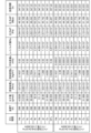
- Fig. 7 is a table showing the calculation results of the penetration time from the start to the completion of gas filling into various glass pipes having different pipe inner diameters D and pipe lengths L of 25,000 m, for several kinds of gases among the various gases listed in Fig. 6.
- the upper part of the table shown in Fig. 7 shows the calculation results of the penetration time from the start to the completion of gas filling into a glass pipe having a pipe inner diameter D of 8.0 x 10 -5 m and a pipe length L of 25,000 m.
- FIG. 7 shows the calculation results of the penetration time from the start to the completion of gas filling into a glass pipe having a pipe inner diameter D of 1.0 x 10 -5 m and a pipe length of 25,000 m.
- FIG. 8 is a table showing the calculation results of the permeation time from the start to the completion of gas filling for various glass pipes having different pipe inner diameters D and a pipe length L of 25,000 m for CF4 among the various gases listed in FIG. 6.
- FIG. 9 is a diagram showing the structure of an experimental system for obtaining the calculation results shown in FIG. 7 and FIG. 8, and a graph showing the calculation results (indicated as "experimental system and calculation results" in FIG. 9). The upper part of FIG. 9 (indicated as "experimental system” in FIG.
- FIG. 9 shows a schematic structure of a glass pipe prepared as an experimental fiber model.
- the middle part of FIG. 9 shows the relationship between the fluid viscosity ⁇ (Pa ⁇ s) and the pressure ⁇ P (MPa) of the gases listed in the upper part of the table shown in FIG. 7.
- the lower part of FIG. 9 shows the relationship between the pipe inner diameter D (m) and the permeation time (h) for CF4 based on the table shown in FIG. 8.
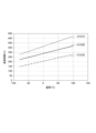
- FIG. 10 is a graph for explaining the temperature dependence of the penetration time for Ar, N 2 , and CF 4 among the gases listed in FIGS.
- a glass pipe with a single pore as shown in the upper part of Figure 9 is assumed as the experimental fiber model.
- This glass pipe has a circular cross section, a pipe inner diameter D, and a pipe length L.
- the pressure loss when a fluid such as a gas is passed through this glass pipe is expressed by the following formula (1).
- the condition of the following formula (2) holds.
- ⁇ is the friction coefficient of the glass pipe against the gas
- L is the pipe length (m)
- D is the pipe inner diameter (m)
- ⁇ is the fluid density (kg/m 3 );
- u is the average flow velocity (m/s);
- ⁇ is the fluid viscosity; and
- Re is the Reynolds number.
- the table shown in FIG . 8 shows the values of the pipe inner diameter D (m), temperature T (K), molecular weight (g/mol), fluid viscosity ⁇ (Pa ⁇ s), fluid density ⁇ (kg/m 3 ), average flow velocity (m/s), Reynolds number Re, pressure ⁇ P (Pa), pressure ⁇ P (MPa), and permeation time (h) for CF 4 as the target gas.
- the graph shown in the lower part of FIG. 9 there is also a correlation between the pipe inner diameter D (m) and the permeation time (h). This tendency can be inferred for other gases.
- the fluid viscosity ⁇ affects the gas filling speed.
- the fluid viscosity ⁇ varies depending on the type of gas and the temperature of the gas. In particular, the effect of temperature is large, and the lower the temperature, the lower the fluid viscosity ⁇ tends to be. Therefore, cooling the fiber intermediate member 150 in FIG. 5 with a thermostatic bath 800 or the like is effective in reducing the permeation time. Such a time dependency of the permeation time is shown in FIG. 10, and the permeation time is reduced by filling the gas at a low temperature regardless of the type of gas.
- the gas to be filled may be one of the gases listed in Fig. 6 etc., which is filled solely in the internal region of the fiber intermediate member 150, or multiple types of gases may coexist in the internal region of the fiber intermediate member 150.
- the line segment G1010 shows the temperature dependence of the permeation time when Ar is selected as the filling gas
- the line segment G1020 shows the temperature dependence of the permeation time when N2 is selected as the filling gas
- the line segment G1030 shows the temperature dependence of the permeation time when CF4 is selected as the filling gas.
- the pipe sample prepared for the measurement has a structure similar to that of the glass pipe shown in the upper part of FIG. 9, the pipe inner diameter D is 8.0 ⁇ 10 ⁇ 5 m, and the pipe length L is 25,000 m.
- the permeation time when the temperature T is 298 K, i.e., 25° C., is adjusted to facilitate comparison.
- the line segment G1010 showing the temperature characteristics of Ar has various parameters, including the fluid viscosity ⁇ , the fluid density ⁇ , the average flow velocity u, the Reynolds number Re, and the pressure ⁇ P, adjusted so that the permeation time when the temperature T is 25° C. is 385 h.
- the line segment G1020 showing the temperature characteristics of N2 has various parameters adjusted, such as the fluid viscosity ⁇ , so that the permeation time when the temperature T is 25° C. is 305 h.
- the line segment G1030 showing the temperature characteristics of CF4 has various parameters adjusted, such as the fluid viscosity, so that the permeation time when the temperature T is 25° C. is 225 h.
- the slope of the line segment G1010 showing the degree of temperature dependency is larger than the remaining line segments G1020 and G1030. In other words, it can be seen that the temperature dependency of Ar is larger than the temperature dependencies of N2 and CF4 .
- the ratio of the total cross-sectional area of the multiple inner cladding elements 121 to the cross-sectional area of the internal region 120b of the outer cladding 120 is set to 0.55 or more as an area ratio. In this way, in the case of the anti-resonant hollow core fiber 100, a sufficient gas-filled space that becomes the hollow optical waveguide region is secured, and it is possible to actually manufacture a fiber having a length of 1 km or more.
- the diameter of the inner region 120b of the outer cladding 120 may be 80 ⁇ m or more. If the diameter of the inner region 120b is 80 ⁇ m or more, the fiber can be efficiently manufactured even if the fiber length is 1 km or more.
- An anti-resonant hollow-core fiber comprising: the anti-resonant hollow-core fiber has a length of 1 km or more; On a cross section of the outer cladding perpendicular to the central axis of the fiber, a remaining region of the inner cladding surrounded by the inner wall surface of the outer cladding, excluding a partial region occupied by the plurality of inner cladding elements, is filled with a gas having an optical absorptance lower than that of H2 and a diffusion coefficient lower than that of Ne in a wavelength band of 1 ⁇ m or more and 2 ⁇ m or less.
- Antiresonant hollow-core fiber On a cross section of the outer cladding perpendicular to the central axis of the fiber, a remaining region of the inner cladding surrounded by the inner wall surface of the outer cladding, excluding a partial region occupied by the plurality of inner cladding elements, is filled with a gas having an optical absorptance lower than that of H2 and a
Landscapes
- Physics & Mathematics (AREA)
- General Physics & Mathematics (AREA)
- Optics & Photonics (AREA)
- Manufacture, Treatment Of Glass Fibers (AREA)
Abstract
An antiresonance hollow-core fiber (100) of the present disclosure is provided with: an outer cladding (120) having a pipe shape extending along a fiber center axis (AX); and a plurality of inner cladding elements (121) that each have a pipe shape and are arranged in an internal region (120b) surrounded by an inner wall surface (120a) of the outer cladding (120), in contact with the inner wall surface (120a) so as to encircle a space forming a core region (110). In a cross section of the internal region (120b), the regions that remain after excluding partial regions occupied by the plurality of inner cladding elements (121) including the internal spaces of the plurality of inner cladding elements (121) are filled with a gas that has a lower optical absorption than H2 in a wavelength band between 1 μm and 2 μm inclusive, and a diffusion coefficient smaller than that of Ne.
Description
本開示は、反共振中空コアファイバに関する。本出願は、2022年9月30日出願の日本出願第2022-157789号に基づく優先権を主張し、前記日本出願に記載された全ての記載内容を援用するものである。
This disclosure relates to an anti-resonant hollow-core fiber. This application claims priority to Japanese Application No. 2022-157789, filed on September 30, 2022, and incorporates by reference all of the contents of said Japanese application.
従来から検討されている中空コアファイバとして、例えば、フォトニック結晶中空コアファイバ(Photonic Cristal Hollow-Core Fiber)および反共振中空コアファイバ(Anti-Resonant Hollow-Core Fiber)が知られている。中空コアファイバは、分光計測によるガス成分測定などへ適用されている。中空コアファイバは、多数のパイプが束ねられた母材を加熱しながら線引きすることで製造される。この製造方法で得られた中空コアファイバの空孔中には、線引き時の圧力制御用ガス、大気等が入っている。
Examples of hollow-core fibers that have been considered include photonic crystal hollow-core fiber and anti-resonant hollow-core fiber. Hollow-core fibers are used for measuring gas components through spectroscopic measurement. Hollow-core fibers are manufactured by drawing a base material made of a number of bundled pipes while heating it. The holes in the hollow-core fiber obtained by this manufacturing method contain gas for controlling the pressure during drawing, atmosphere, etc.
フォトニック結晶中空コアファイバは、例えば非特許文献1に開示されたように、フォトニックバンドギャップを利用して光閉じ込めを制御する中空コアファイバである。フォトニック結晶中空コアファイバのクラッド内には、多数の空孔が波長オーダーの周期構造構成するように配置されている。多数の空孔で取り囲まれたコア領域となる空間の断面積は数十μm2から100μm2と小さい。そのため、該空孔内への高圧ガス注入が抑制されている。
A photonic crystal hollow-core fiber is a hollow-core fiber that controls light confinement by utilizing a photonic band gap, as disclosed in, for example, Non-Patent Document 1. A large number of holes are arranged in the cladding of the photonic crystal hollow-core fiber so as to form a periodic structure on the order of wavelength. The cross-sectional area of the space that becomes the core region surrounded by the large number of holes is small, ranging from several tens of μm2 to 100 μm2 . Therefore, the injection of high-pressure gas into the holes is suppressed.
反共振中空コアファイバでは、例えば特許文献1および非特許文献2に開示されたように、外側クラッドの内部領域がファイバ中心軸に沿って連続した断面構造を有している。その断面積は、数千μm2となる。そのため、ファイバ端面からガスを注入する時間を、上述のフォトニック結晶中空コアファイバと比較して大幅に減少させることが可能になる。
In an anti-resonant hollow-core fiber, as disclosed in, for example, Patent Document 1 and Non-Patent Document 2, the inner region of the outer cladding has a continuous cross-sectional structure along the central axis of the fiber. The cross-sectional area is several thousand μm2 . Therefore, it is possible to significantly reduce the time required to inject gas from the fiber end face, as compared with the above-mentioned photonic crystal hollow-core fiber.
本開示の反共振中空コアファイバは、パイプ形状を有する外側クラッドと、パイプ形状をそれぞれ有する複数の内側クラッド要素と、を備える。外側クラッドのパイプ形状は、ファイバ中心軸に沿って伸びる。複数の内側クラッド要素は、外側クラッドの内壁面に接触した状態でコア領域となる空間を取り囲むようにそれぞれ配置される。また、ファイバ中心軸に直交する反共振中空コアファイバの断面において、外側クラッドの内壁面で囲まれた内部領域のうち、複数の内側クラッド要素の内部空間を含む、複数の内側クラッド要素が占める部分領域を除いた残りの領域には、1μm以上2μm以下の波長帯においてH2よりも低い光吸収率とNeよりも小さい拡散係数とを有するガスが充填されている。
The anti-resonant hollow core fiber of the present disclosure includes an outer cladding having a pipe shape and a plurality of inner cladding elements each having a pipe shape. The pipe shape of the outer cladding extends along the fiber central axis. The inner cladding elements are arranged to surround a space that becomes a core region while in contact with an inner wall surface of the outer cladding. In addition, in a cross section of the anti-resonant hollow core fiber perpendicular to the fiber central axis, the inner region surrounded by the inner wall surface of the outer cladding, except for a partial region occupied by the inner cladding elements including the inner space of the inner cladding elements, is filled with a gas having an optical absorptance lower than H2 and a diffusion coefficient lower than Ne in a wavelength band of 1 μm to 2 μm.
[本開示が解決しようとする課題]
発明者らは、上述の従来技術について検討した結果、以下のような課題を発見した。すなわち、上述の従来技術では、中空コアファイバ内への外部からのガスの侵入、中空コアファイバの空孔に充填されたガスの拡散による消失、または、中空コアファイバの空孔に充填されたガスのガラスへの侵入を回避することができなかった。そのため、上述の従来技術では、ガスが充填された空孔における屈折率や、進入したガスとガラス表面との反応により、伝送損失が経時的に変化するという課題があった。また、上述の従来技術では、非線形光学効果や光吸収を利用することを前提としていたこと、および、膨大な製造時間が必要になることから、長尺ファイバ内への積極的なガス充填は行われていなかった。 [Problem that this disclosure aims to solve]
The inventors have studied the above-mentioned conventional techniques and found the following problems. That is, the above-mentioned conventional techniques could not avoid the intrusion of gas from the outside into the hollow core fiber, the loss of the gas filled in the holes of the hollow core fiber due to diffusion, or the intrusion of the gas filled in the holes of the hollow core fiber into the glass. Therefore, the above-mentioned conventional techniques had a problem that the transmission loss changes over time due to the refractive index in the holes filled with gas and the reaction between the invaded gas and the glass surface. In addition, the above-mentioned conventional techniques were premised on the use of nonlinear optical effects and optical absorption, and required a huge manufacturing time, so that gas was not actively filled into the long fiber.
本開示は、上述のような課題を解決するためになされたものであり、従来技術と比較して長尺化および伝送損失の安定化を可能にするための構造を有する反共振中空コアファイバを提供することを目的としている。
The present disclosure has been made to solve the problems described above, and aims to provide an anti-resonant hollow-core fiber having a structure that enables longer lengths and more stable transmission losses compared to conventional techniques.
[本開示の効果]
本開示の反共振中空コアファイバによれば、従来技術と比較して長尺化および伝送損失の安定化が可能になる。 [Effects of this disclosure]
The anti-resonant hollow-core fiber of the present disclosure enables longer lengths and more stable transmission losses compared to conventional techniques.
本開示の反共振中空コアファイバによれば、従来技術と比較して長尺化および伝送損失の安定化が可能になる。 [Effects of this disclosure]
The anti-resonant hollow-core fiber of the present disclosure enables longer lengths and more stable transmission losses compared to conventional techniques.
[本開示の実施態様の説明]
最初に本開示の実施形態の内容をそれぞれ個別に列挙して説明する。
(1)反共振中空コアファイバは、パイプ形状を有する外側クラッドと、パイプ形状をそれぞれ有する複数の内側クラッド要素と、を備える。外側クラッドのパイプ形状は、ファイバ中心軸に沿って伸びる。複数の内側クラッド要素は、外側クラッドの内壁面に接触した状態で、コア領域となる空間を取り囲むように、外側クラッド内にそれぞれ配置される。また、ファイバ中心軸に直交する反共振中空コアファイバの断面において、外側クラッドの内壁面で囲まれた内部領域のうち、複数の内側クラッド要素の内部空間を含む、複数の内側クラッド要素が占める部分領域を除いた残りの領域には、1μm以上2μm以下の波長帯においてH2(水素)よりも低い光吸収率とNe(ネオン)よりも小さい拡散係数とを有するガスが充填されている。 [Description of the embodiments of the present disclosure]
First, the contents of the embodiments of the present disclosure will be individually listed and described.
(1) An anti-resonant hollow-core fiber includes an outer cladding having a pipe shape and a plurality of inner cladding elements each having a pipe shape. The pipe shape of the outer cladding extends along the fiber central axis. The inner cladding elements are disposed in the outer cladding so as to surround a space that becomes a core region while being in contact with an inner wall surface of the outer cladding. In addition, in a cross section of the anti-resonant hollow-core fiber perpendicular to the fiber central axis, an inner region surrounded by the inner wall surface of the outer cladding, except for a partial region occupied by the inner cladding elements including the inner spaces of the inner cladding elements, is filled with a gas having an optical absorptance lower than H 2 (hydrogen) and a diffusion coefficient lower than Ne (neon) in a wavelength band of 1 μm or more and 2 μm or less.
本開示の反共振中空コアファイバによれば、コア領域となる中空光導波領域に1μm以上かつ2μm以下の波長帯においてH2よりも低い光吸収率とNeよりも小さい拡散係数とを有するガスが充填されている。この構成により、従来技術と比較して伝送損失の経時的変化が抑制される。加えて、非線形光学効果や光吸収を利用する従来の中空コアファイバでは、長尺ファイバ内への積極的なガス充填は行われていなかった。これに対し、本開示の反共振中空コアファイバによれば、上記中空光導波領域となるガス充填空間の確保が容易になるとともにH2よりも低い光吸収率かつNeよりも小さい拡散係数を有するガスが選択的にファイバ内に充填されるため、伝送損失の経時的変化が抑制された安定したファイバ空間が得られる。その結果、ファイバ空間の1km以上の長尺化も可能になる。特に、外側クラッドの内部領域に1気圧以上の圧力をかけてガスを充填することにより、曲げや側圧によるファイバの変形が抑制される効果も期待される。
According to the anti-resonant hollow core fiber of the present disclosure, the hollow optical waveguide region serving as the core region is filled with a gas having an optical absorptance lower than H2 and a diffusion coefficient smaller than Ne in the wavelength band of 1 μm or more and 2 μm or less. This configuration suppresses the change in transmission loss over time compared to the conventional technology. In addition, in conventional hollow core fibers utilizing nonlinear optical effects and optical absorption, gas was not actively filled into the long fiber. In contrast, according to the anti-resonant hollow core fiber of the present disclosure, it is easy to secure the gas-filled space serving as the hollow optical waveguide region, and a gas having an optical absorptance lower than H2 and a diffusion coefficient smaller than Ne is selectively filled into the fiber, so that a stable fiber space in which the change in transmission loss over time is suppressed can be obtained. As a result, the fiber space can be made longer by 1 km or more. In particular, by filling the inner region of the outer cladding with gas by applying a pressure of 1 atmosphere or more, the effect of suppressing deformation of the fiber due to bending or lateral pressure is also expected.
(2)上記(1)において、1km以上の長さを有してもよい。ガスが充填された結果、反共振中空コアファイバの長尺化が可能になる。
(2) In the above (1), the length may be 1 km or more. As a result of being filled with gas, the anti-resonant hollow-core fiber can be made longer.
(3)上記(1)または(2)において、反共振中空コアファイバの断面の面積比として、内部領域の断面積に対する、複数の内側クラッド要素の総断面積の比は、0.55以上であってもよい。この場合、ガス充填空間が十分に確保される。その結果、ガス充填時間の短縮および反共振中空コアファイバの長尺化が可能になる。
(3) In the above (1) or (2), the ratio of the total cross-sectional area of the multiple inner cladding elements to the cross-sectional area of the internal region may be 0.55 or more as the area ratio of the cross-section of the anti-resonant hollow core fiber. In this case, sufficient gas filling space is ensured. As a result, it is possible to shorten the gas filling time and to lengthen the anti-resonant hollow core fiber.
(4)上記(3)において、複数の内側クラッド要素の個数は3個以上6個以下であればよい。外側クラッド内にコア領域を取り囲む3個以上の内側クラッド要素が配置されれば、光閉じ込め効果が発揮される。また、内側クラッド要素の個数を6個以下に制限することにより、上記面積比を満たした状態で十分なガス充填空間を確保するためのファイバ設計の自由度を向上させることができる。
(4) In the above (3), the number of multiple inner cladding elements may be 3 to 6 inclusive. If three or more inner cladding elements are arranged in the outer cladding to surround the core region, an optical confinement effect is achieved. In addition, by limiting the number of inner cladding elements to 6 or less, the degree of freedom in fiber design can be improved to ensure sufficient gas filling space while satisfying the above area ratio.
(5)上記(3)または(4)において、内部領域の直径が80μm以上であってもよい。内部領域の直径が80μm以上であれば、ガスの充填時間が短くなり、効率的に製造可能である。
(5) In the above (3) or (4), the diameter of the inner region may be 80 μm or more. If the diameter of the inner region is 80 μm or more, the gas filling time is shortened, and efficient manufacturing is possible.
(6)上記(1)から上記(5)のいずれかにおいて、反共振中空コアファイバ内に充填されるガスは、Ar(アルゴン)、Kr(クリプトン)、Xe(キセノン)、N2(窒素)、O2(酸素)、CF4(テトラフルオロメタン)、C2F6(ヘキサフルオロエタン)、CCl2F2(ジクロロジフルオロメタン、)、CClF3(クロロトリフルオロメタン)のうち少なくとも1つを含んでもよい。すなわち、反共振中空コアファイバの内部領域に相当する外側クラッドの内部領域には、ここに列挙されたAr等の一種類のガスが充填されてもよく、また、内部領域において複数種類のガスが共存してもよい。いずれのガスによっても、従来と比較して伝送損失の安定化が実現される。特に、外側クラッドの内部領域に複数種類のガスを共存させる構成では、反共振中空コアファイバの長手方向に沿って異なるガスの組成分布が形成でき、長手方向に沿った屈折率変化を利用した伝送特性の改善などが期待できる。
(6) In any of the above (1) to (5), the gas filled in the anti-resonant hollow core fiber may include at least one of Ar (argon), Kr (krypton), Xe (xenon), N 2 (nitrogen), O 2 (oxygen), CF 4 (tetrafluoromethane), C 2 F 6 (hexafluoroethane), CCl 2 F 2 (dichlorodifluoromethane), and CClF 3 (chlorotrifluoromethane). That is, the inner region of the outer cladding corresponding to the inner region of the anti-resonant hollow core fiber may be filled with one type of gas such as Ar listed here, or multiple types of gases may coexist in the inner region. With any gas, the transmission loss is stabilized compared to the conventional case. In particular, in a configuration in which multiple types of gases coexist in the inner region of the outer cladding, different gas composition distributions can be formed along the longitudinal direction of the anti-resonant hollow core fiber, and improvement of transmission characteristics utilizing refractive index changes along the longitudinal direction can be expected.
(7)上記(1)から上記(6)のいずれかにおいて、反共振中空コアファイバ内に充填されるガスの圧力は、摂氏25度の温度で0.101МPaより大きく、かつ70МPaより小さくてもよい。伝送損失の経時的変化が抑制された安定した伝送特性を維持できる。
(7) In any of (1) to (6) above, the pressure of the gas filled in the anti-resonant hollow-core fiber may be greater than 0.101 MPa and less than 70 MPa at a temperature of 25 degrees Celsius. Stable transmission characteristics can be maintained with suppressed changes in transmission loss over time.
[本開示の実施形態の詳細]
本開示の反共振中空コアファイバの具体例を、以下に添付の図面を参照しながら詳細に説明する。なお、本開示は、これら例示に限定されるものではなく、請求の範囲によって示され、また、請求の範囲と均等の意味および範囲内での全ての変更が含まれることが意図されている。また、図面の説明において同一の要素には同一符号を付して重複する説明を省略する。 [Details of the embodiment of the present disclosure]
Specific examples of the anti-resonant hollow-core fiber of the present disclosure will be described in detail below with reference to the accompanying drawings. Note that the present disclosure is not limited to these examples, but is indicated by the claims, and is intended to include all modifications within the meaning and scope equivalent to the claims. In addition, in the description of the drawings, the same elements are given the same reference numerals, and duplicated descriptions are omitted.
図1は、本開示の反共振中空コアファイバの構造を示す図である。また、図2は、本開示の反共振中空コアファイバの主要部分の断面構造を、比較例のフォトニック結晶中空コアファイバの対応する主要部の断面構造とともに説明するための図である(図2中、「断面構造」と記す)。図2の上段(図2中、「反共振型」と記す)には、図1中に示されたI-I線に沿った、反共振中空コアファイバの主要部分の断面図が示されている。図2の下段(図2中、「フォトニック結晶型」と記す)には、比較例として、図1中に示されたI-I線に沿った断面に相当する、フォトニック結晶中空コアファイバの主要部分の断面図が示されている。
FIG. 1 is a diagram showing the structure of an antiresonant hollow core fiber of the present disclosure. FIG. 2 is a diagram for explaining the cross-sectional structure of the main part of the antiresonant hollow core fiber of the present disclosure together with the cross-sectional structure of the corresponding main part of a photonic crystal hollow core fiber of a comparative example (indicated as "cross-sectional structure" in FIG. 2). The upper part of FIG. 2 (indicated as "antiresonant type" in FIG. 2) shows a cross-sectional view of the main part of the antiresonant hollow core fiber along line I-I shown in FIG. 1. The lower part of FIG. 2 (indicated as "photonic crystal type" in FIG. 2) shows a cross-sectional view of the main part of a photonic crystal hollow core fiber, as a comparative example, corresponding to the cross section along line I-I shown in FIG. 1.
図1に示されたように、本開示の反共振中空コアファイバ100は、外側クラッド120、複数の内側クラッド要素121、ジャケット層130、および樹脂被覆140と、を備える。外側クラッド120は、光学クラッドとして機能し、ファイバ中心軸AXに沿って伸びたパイプ形状を有する。外側クラッド120の内壁面120aで囲まれた内部領域120bは、反共振中空コアファイバ100の内部領域に相当し、内部領域120bには、トレンチ層として機能する複数の内側クラッド要素121が設けられている。これら複数の内側クラッド要素121は、いずれの内側クラッド要素121も外側クラッド120の内壁面120aに接触した状態で、中空光導波領域として機能するコア領域110となる空間を取り囲むように配置されている。コア領域110となる空間は、ファイバ中心軸AXに沿って伸びている。外側クラッド120の外周には、物理クラッドとなるジャケット層130が設けられている。さらに、ジャケット層130の外周には、樹脂被覆140が設けられている。
As shown in FIG. 1, the anti-resonant hollow core fiber 100 of the present disclosure comprises an outer cladding 120, a plurality of inner cladding elements 121, a jacket layer 130, and a resin coating 140. The outer cladding 120 functions as an optical cladding and has a pipe shape extending along the fiber central axis AX. The inner region 120b surrounded by the inner wall surface 120a of the outer cladding 120 corresponds to the inner region of the anti-resonant hollow core fiber 100, and the inner region 120b is provided with a plurality of inner cladding elements 121 functioning as a trench layer. These inner cladding elements 121 are arranged to surround a space that becomes the core region 110 that functions as a hollow optical waveguide region, with all of the inner cladding elements 121 in contact with the inner wall surface 120a of the outer cladding 120. The space that becomes the core region 110 extends along the fiber central axis AX. The outer cladding 120 is surrounded by a jacket layer 130 that becomes a physical cladding. Furthermore, a resin coating 140 is provided on the outer periphery of the jacket layer 130.
図2の上段に示されたように、ファイバ中心軸AXに直交する外側クラッド120の断面上、すなわちファイバ中心軸AXに直交する内部領域120bの断面において、外側クラッド120の内壁面120aで囲まれた内部領域120bのうち、複数の内側クラッド要素の内部空間121bを含む、複数の内側クラッド要素121が占める部分領域を除いた残りの領域には、特定のガスが充填されている。以下では、ガスが充填されるこの領域を、ガス充填領域と呼び、充填されるガスを充填ガスと呼ぶ。この充填ガスは、1μm以上かつ2μm以下の波長帯においてH2よりも低い光吸収率とNeよりも小さい拡散係数とを有する。この充填ガスは、例えば、希ガス、一般ガス、ハロゲン化カーボン等から選択される。希ガスでは、Ar、Kr、およびXeのいずれかであればよい。一般ガスでは、N2およびO2のいずれかであればよい。また、ハロゲン化カーボンでは、CF4、C2F6、CCl2F2、CClF3のいずれかであればよい。
As shown in the upper part of FIG. 2, on the cross section of the outer cladding 120 perpendicular to the fiber central axis AX, i.e., in the cross section of the inner region 120b perpendicular to the fiber central axis AX, the inner region 120b surrounded by the inner wall surface 120a of the outer cladding 120, excluding the partial region occupied by the inner cladding elements 121 including the inner space 121b of the inner cladding elements, is filled with a specific gas. Hereinafter, this region filled with gas is called a gas-filled region, and the filled gas is called a filling gas. This filling gas has a light absorption rate lower than H2 and a diffusion coefficient smaller than Ne in the wavelength band of 1 μm or more and 2 μm or less. This filling gas is selected from, for example, rare gas, general gas, halogenated carbon, etc. The rare gas may be any of Ar, Kr, and Xe. The general gas may be any of N2 and O2 . The carbon halide may be any one of CF 4 , C 2 F 6 , CCl 2 F 2 and CClF 3 .
なお、比較例として図2の下段に示されたフォトニック結晶中空コアファイバは、共通クラッド220を備え、この共通クラッド220内には、コア領域210となる中空光導波領域を取り囲むように配置された多数の空孔221が配置されている。ファイバ中心軸AXに直交する共通クラッド220の断面上、すなわちフォトニック結晶中空コアファイバの断面上において、多数の空孔221は、波長オーダーで周期構造を構成するよう配置されている。この周期構造により生じるフォトニックバンドギャップによって光がコア領域210内に閉じ込められる。
The photonic crystal hollow-core fiber shown in the lower part of Figure 2 as a comparative example has a common cladding 220, in which a large number of air holes 221 are arranged so as to surround a hollow optical waveguide region that becomes the core region 210. On a cross section of the common cladding 220 perpendicular to the fiber central axis AX, i.e., on a cross section of the photonic crystal hollow-core fiber, the large number of air holes 221 are arranged so as to form a periodic structure on the order of wavelength. Light is confined within the core region 210 by the photonic band gap caused by this periodic structure.
図2の上段に示された反共振中空コアファイバ100のガス充填可能な空間は、上記のガス充填領域である。一方、図2の下段に示されたフォトニック結晶中空コアファイバのガス充填可能な空間は、共通クラッド220の内部に配置された多数の空孔221で取り囲まれたコア領域210のみである。このように、本開示の反共振中空コアファイバ100と比較例のフォトニック結晶中空コアファイバとでは、ガス充填可能な空間の断面積の差が著しく大きくなっている。このような断面積の差は、後述するガス充填の開始から完了までの浸透時間の差として顕在化する。
The gas-fillable space of the antiresonant hollow core fiber 100 shown in the upper part of Figure 2 is the gas-filled region described above. On the other hand, the gas-fillable space of the photonic crystal hollow core fiber shown in the lower part of Figure 2 is only the core region 210 surrounded by a large number of holes 221 arranged inside the common cladding 220. In this way, there is a significant difference in the cross-sectional area of the gas-fillable space between the antiresonant hollow core fiber 100 of the present disclosure and the photonic crystal hollow core fiber of the comparative example. This difference in cross-sectional area manifests itself as a difference in the penetration time from the start to the completion of gas filling, which will be described later.
図3は、本開示の反共振中空コアファイバ100の断面における面積比の計算を説明するための図である(図3中、「面積比計算」と記す)。図3の上段(図3中、「断面モデル」と記す)には、図2の上段に示された反共振中空コアファイバ100の断面に相当する断面モデルが示されている。図3の下段(図3中、「拡大図」と記す)には、外側クラッド120と内側クラッド要素121の一つとの実際の接触状態を概念的に示すか拡大図である。
Figure 3 is a diagram for explaining the calculation of the area ratio in the cross section of the antiresonant hollow-core fiber 100 of the present disclosure (marked "Area Ratio Calculation" in Figure 3). The upper part of Figure 3 (marked "Cross-Section Model" in Figure 3) shows a cross-section model equivalent to the cross section of the antiresonant hollow-core fiber 100 shown in the upper part of Figure 2. The lower part of Figure 3 (marked "Enlarged View" in Figure 3) is an enlarged view conceptually showing the actual contact state between the outer cladding 120 and one of the inner cladding elements 121.
図3において、r1は、外側クラッド120の内部領域120bの半径である。すなわち、中心軸AXから外側クラッド120の内壁面120aまでの距離がr1である。r2は、中心121aから外周面までの、内側クラッド要素121の半径である。ただし、内側クラッド要素121は、図3の下段に示されたように外側クラッド120の内壁面120aにめり込む。そのため、面積比の計算では、その補正値としてr3が利用される。また、dは、隣接する内側クラッド要素121間の距離である。θは、ファイバ断面上に設定された基準線と、ファイバ中心軸AXと内側クラッド要素121の中心121aを結ぶ線分と、のなす角度である。なお、内側クラッド要素121の半径r2の補正値r3は、式「r1/(1+1/sin(π/n))-d/2」で計算される。nは、内側クラッド要素121の個数である。そのため、外側クラッド120の内部領域120bの断面積に対する内側クラッド要素121の総断面積の比(以下、「面積比」と記す)は、n×(r3/r1)2で与えられる。
In FIG. 3, r1 is the radius of the inner region 120b of the outer cladding 120. That is, the distance from the central axis AX to the inner wall surface 120a of the outer cladding 120 is r1. r2 is the radius of the inner cladding element 121 from the center 121a to the outer peripheral surface. However, the inner cladding element 121 is embedded in the inner wall surface 120a of the outer cladding 120 as shown in the lower part of FIG. 3. Therefore, in the calculation of the area ratio, r3 is used as a correction value. Also, d is the distance between the adjacent inner cladding elements 121. θ is the angle between the reference line set on the fiber cross section and the line segment connecting the fiber central axis AX and the center 121a of the inner cladding element 121. The correction value r3 of the radius r2 of the inner cladding element 121 is calculated by the formula "r1/(1+1/sin(π/n))-d/2". n is the number of inner cladding elements 121. Therefore, the ratio of the total cross-sectional area of the inner cladding elements 121 to the cross-sectional area of the inner region 120b of the outer cladding 120 (hereinafter referred to as the "area ratio") is given by n x (r3/r1) 2 .
具体的には、共通パラメータとして、外側クラッド120の内部領域120bの半径r1を40μm、内側クラッド要素121間の距離dを2μmに固定する。この場合、定性的には、外側クラッド120の内壁面120aに接触する内側クラッド要素121の個数増加に伴い、補正値r3で与えられる各内側クラッド要素121の半径は小さくなる。同様に、個数増加に伴い、面積比も小さくなる。
Specifically, as common parameters, the radius r1 of the inner region 120b of the outer cladding 120 is fixed at 40 μm, and the distance d between the inner cladding elements 121 is fixed at 2 μm. In this case, qualitatively, as the number of inner cladding elements 121 in contact with the inner wall surface 120a of the outer cladding 120 increases, the radius of each inner cladding element 121 given by the correction value r3 becomes smaller. Similarly, as the number increases, the area ratio also becomes smaller.
例えば、内側クラッド要素121の個数の条件がn=3の場合、半径r2の補正値r3および半径比: r3/r1はそれぞれ17.6μmおよび0.44であり、面積比:n×(r3/r1)2は0.58となる。なお、n<3の場合、内側クラッド要素121がトレンチ層として機能しなくなるため、内側クラッド要素121は3個以上必要になる。また、n=4の場合、r3=15.6μmおよびr3/r1=0.39であり、n×(r3/r1)2は0.61となる。n=5の場合、r3=13.8μmおよびr3/r1=0.35であり、n×(r3/r1)2は0.60となる。n=6の場合、r3=12.3μmおよびr3/r1=0.31であり、n×(r3/r1)2は0.57となる。n=7の場合、r3=11.1μmおよびr3/r1=0.28であり、n×(r3/r1)2は0.54となる。さらに、n=8の場合、r3=10.1μmおよびr3/r1=0.25であり、n×(r3/r1)2は0.51となる。なお、n=8の場合およびn=7の場合は、n=6の場合と比較して面積比:n×(r3/r1)2は小さくなっており、隣接する2個の内側クラッド要素121と外側クラッド120の内壁面120aで囲まれた領域の断面積は、小さくなり過ぎてしまう。これらの場合、外側クラッド120の内部領域120b内に高圧注入されるガスと残留ガスの入れ替えが難しくなる。換言すれば、内側クラッド要素121の個数が7個以上の場合、反共振中空コアファイバ内への均一なガス充填が難しくなる。その結果、該反共振中空コアファイバのファイバ中心軸に沿った、伝送損失などの光学特性の安定化が実現できなくなる。そのため、ガス充填のための十分な空間を確保するとともに長手方向に沿って安定した伝送損失などの光学特性を実現するためは、内側クラッド要素121の個数が6個以下であればよく、上記面積比:n×(r3/r1)2は、0.55以上であればよい。面積比を計算するために必要な上記の各半径は、端面の顕微観察により測定できる。また、内側クラッド要素121の個数は、3個以上かつ6個以下であってもよいから、上記面積比は0.57以上かつ0.61以下であってもよい。外側クラッド120の内部領域120bの半径r1が40μmより大きい場合には、上記面積比は0.61以上となることもあり得る。
For example, when the condition for the number of the inner cladding elements 121 is n=3, the correction value r3 of the radius r2 and the radius ratio: r3/r1 are 17.6 μm and 0.44, respectively, and the area ratio: n×(r3/r1) 2 is 0.58. Note that when n<3, the inner cladding elements 121 do not function as a trench layer, so three or more inner cladding elements 121 are required. When n=4, r3=15.6 μm and r3/r1=0.39, and n×(r3/r1) 2 is 0.61. When n=5, r3=13.8 μm and r3/r1=0.35, and n×(r3/r1) 2 is 0.60. When n=6, r3=12.3 μm and r3/r1=0.31, and n×(r3/r1) 2 is 0.57. When n=7, r3=11.1 μm and r3/r1=0.28, and n×(r3/r1) 2 is 0.54. When n=8, r3=10.1 μm and r3/r1=0.25, and n×(r3/r1) 2 is 0.51. When n=8 and n=7, the area ratio: n×(r3/r1) 2 is smaller than when n=6, and the cross-sectional area of the region surrounded by two adjacent inner cladding elements 121 and the inner wall surface 120a of the outer cladding 120 becomes too small. In these cases, it becomes difficult to replace the gas injected at high pressure into the internal region 120b of the outer cladding 120 with the residual gas. In other words, when the number of inner cladding elements 121 is 7 or more, it becomes difficult to uniformly fill the anti-resonant hollow core fiber with gas. As a result, it becomes impossible to realize stabilization of optical characteristics such as transmission loss along the fiber central axis of the anti-resonant hollow-core fiber. Therefore, in order to secure a sufficient space for gas filling and realize optical characteristics such as stable transmission loss along the longitudinal direction, the number of inner cladding elements 121 may be 6 or less, and the above area ratio: n×(r3/r1) 2 may be 0.55 or more. The above radii required for calculating the area ratio can be measured by microscopic observation of the end face. In addition, the number of inner cladding elements 121 may be 3 or more and 6 or less, so the above area ratio may be 0.57 or more and 0.61 or less. When the radius r1 of the inner region 120b of the outer cladding 120 is greater than 40 μm, the above area ratio may be 0.61 or more.
次に、本開示の反共振中空コアファイバ100の製造方法について前半工程と後半工程に分けて説明する。図4は、本開示の反共振中空コアファイバ100の製造方法のうち前半工程に相当する線引き工程を説明するための図である。また、図5は、本開示の反共振中空コアファイバ100の製造方法のうち後半工程に相当するガス充填工程を説明するための図である。
Next, the manufacturing method of the antiresonant hollow core fiber 100 of the present disclosure will be described in two parts, the first half and the second half. Figure 4 is a diagram for explaining the drawing process, which corresponds to the first half of the manufacturing method of the antiresonant hollow core fiber 100 of the present disclosure. Also, Figure 5 is a diagram for explaining the gas filling process, which corresponds to the second half of the manufacturing method of the antiresonant hollow core fiber 100 of the present disclosure.
図4に示された線引き装置は、前半工程を実施するため、線引き対象の光ファイバ母材10の内部を加圧する加圧装置300と、光ファイバ母材10の一端を加熱するヒーター400と、光ファイバ母材10から引き出された中空のガラスファイバの表面に樹脂を塗布する樹脂塗布装置500と、ファイバ中間部材150を巻き取るための巻き取り装置600と、ファイバ中間部材150の進行方向を調整するためのローラー610と、を備える。
The drawing device shown in FIG. 4 is equipped with a pressure device 300 that applies pressure to the inside of the optical fiber preform 10 to be drawn in order to carry out the first half of the process, a heater 400 that heats one end of the optical fiber preform 10, a resin application device 500 that applies resin to the surface of the hollow glass fiber pulled out from the optical fiber preform 10, a winding device 600 that winds up the fiber intermediate member 150, and a roller 610 that adjusts the traveling direction of the fiber intermediate member 150.
光ファイバ母材10は、パイプ形状を有し線引き後に外側クラッド120となる外側クラッド部12と、パイプ形状を有し線引き後に内側クラッド要素121となる複数の内側クラッド部12bと、線引き後にジャケット層130となるジャケット部13と、により構成される。外側クラッド部12の内壁面12aに囲まれた内部領域には、複数の内側クラッド部12bのそれぞれが内壁面12aに接触した状態で外側クラッド部12の中心を取り囲むように配置されている。また、外側クラッド120の外周上にはジャケット部13が設けられている。
The optical fiber preform 10 is composed of an outer cladding portion 12 that has a pipe shape and becomes the outer cladding 120 after drawing, a plurality of inner cladding portions 12b that have a pipe shape and become inner cladding elements 121 after drawing, and a jacket portion 13 that becomes the jacket layer 130 after drawing. In the internal region surrounded by the inner wall surface 12a of the outer cladding portion 12, the plurality of inner cladding portions 12b are arranged so as to surround the center of the outer cladding portion 12 while each of them is in contact with the inner wall surface 12a. In addition, a jacket portion 13 is provided on the outer periphery of the outer cladding 120.
ヒーター400により加熱されて軟化した光ファイバ母材10の一端は、巻き取り装置600のドラムが矢印Sで示された方向に回転することにより、光ファイバ母材10の一端から、中空のガラスファイバが引き出される。その際、外側クラッド部12の内部領域および複数の内側クラッド部12bのそれぞれの内部領域には、加圧装置300により圧力制御用ガスや空気が供給されており、これら内部領域はパイプ形状が変形しないように加圧状態になっている。引き出されたガラスファイバの表面には、樹脂塗布装置500により樹脂が塗布され、ファイバ中間部材150が得られる。このファイバ中間部材150は、外側クラッド120に相当する線引き後の部分の内部領域および複数の内側クラッド要素121のそれぞれに相当する線引き後の部分の内部領域が中空状態になっている。得られたファイバ中間部材150は、最終的に、ローラー610を介して巻き取り装置600のドラムに巻き取られる。
The end of the optical fiber preform 10 is heated and softened by the heater 400, and the drum of the winding device 600 rotates in the direction indicated by the arrow S, so that a hollow glass fiber is drawn out from the end of the optical fiber preform 10. At this time, the pressure control gas or air is supplied by the pressurizing device 300 to the internal region of the outer cladding portion 12 and the internal region of each of the multiple inner cladding portions 12b, and these internal regions are in a pressurized state so as not to deform the pipe shape. Resin is applied to the surface of the drawn glass fiber by the resin application device 500, and the fiber intermediate member 150 is obtained. In this fiber intermediate member 150, the internal region of the part after drawing corresponding to the outer cladding 120 and the internal region of the part after drawing corresponding to each of the multiple inner cladding elements 121 are in a hollow state. The obtained fiber intermediate member 150 is finally wound up on the drum of the winding device 600 via the roller 610.
さらに、上述のような構造を備えた線引き装置により得られたファイバ中間部材150は、図5に示された、ガス充填工程を実施する装置にセットされ、後半工程が実施される。すなわち、図5に示された装置は、高圧ガス供給システム710と、真空ポンプ720と、ガス分析計730と、を備える。ファイバ中間部材150の一方の端面は、開閉弁741を介して高圧ガス供給システム710に接続されている。開閉弁741を介して高圧ガス供給システム710から充填ガスがファイバ中間部材150の一方の端面に供給されると、該充填ガスは、ガス充填領域に、供給される。なお、複数の内側クラッド要素121に相当する部分の内部空間121bは、真空または減圧された状態となっているため、これら複数の内側クラッド要素121に相当する部分には充填ガスは進入していかない。また、複数の内側クラッド要素121に相当する部分の内部空間121bは断面積が小さいため、複数の内側クラッド要素121に相当する部分の内部空間121bにガスを充填しても、ガス充填領域にガスを充填するのにかかる時間内には、ガスの充填は完了しない。
Furthermore, the fiber intermediate member 150 obtained by the drawing device having the above-mentioned structure is set in the device for performing the gas filling process shown in FIG. 5, and the latter half of the process is performed. That is, the device shown in FIG. 5 is equipped with a high-pressure gas supply system 710, a vacuum pump 720, and a gas analyzer 730. One end face of the fiber intermediate member 150 is connected to the high-pressure gas supply system 710 via an on-off valve 741. When the filling gas is supplied from the high-pressure gas supply system 710 to one end face of the fiber intermediate member 150 via the on-off valve 741, the filling gas is supplied to the gas filling area. Note that the internal space 121b of the part corresponding to the multiple inner cladding elements 121 is in a vacuum or reduced pressure state, so the filling gas does not enter the part corresponding to these multiple inner cladding elements 121. In addition, because the cross-sectional area of the internal space 121b in the portion corresponding to the multiple inner cladding elements 121 is small, even if gas is filled into the internal space 121b in the portion corresponding to the multiple inner cladding elements 121, the filling of the gas will not be completed within the time it takes to fill the gas filling region with gas.
ファイバ中間部材150の他方の端面には、開閉弁742を介して真空ポンプ720が接続されており、この真空ポンプ720により、ファイバ中間部材150の内部領域、すなわち外側クラッド120の内部領域120bに相当する領域内の残留ガスが排気される。真空ポンプ720により排気されるガスの種類はガス分析計730により分析される。ガス分析計730により充填ガスが検出された時点で、ガスの充填が完了し、外側クラッド120の内部領域120bに相当するファイバ中間部材150の内部領域において、残留ガスが充填ガスに入れ替えられたことが確認できる。ガスの充填後、反共振中空コアファイバ100の両端部を機密封止すれば、ガスの圧力は封止時の圧力が維持される。封止時の反共振中空コアファイバ100の中に充填されたガスの圧力は、摂氏25度の温度で0.101МPaより大きく、かつ70MPaより小さい。充填中のガスの圧力は、高圧ガス供給システム710に備えられた圧力計により測定できる。充填後の反共振中空コアファイバ100の中に充填されたガスの種類とガスの圧力は、ガス分析計730および高圧ガス供給システム710に反共振中空コアファイバ100を再び接続することで測定できる。また、充填後の反共振中空コアファイバ100の中に充填されたガスの種類とガスの圧力は、ラマン分光法や誘導ラマン散乱等の分光測定から得られたスペクトルの、面積強度やピーク強度から推定することもできる。
A vacuum pump 720 is connected to the other end face of the fiber intermediate member 150 via an on-off valve 742, and the vacuum pump 720 exhausts the residual gas in the internal region of the fiber intermediate member 150, i.e., the region corresponding to the internal region 120b of the outer cladding 120. The type of gas exhausted by the vacuum pump 720 is analyzed by a gas analyzer 730. When the gas analyzer 730 detects the filling gas, it can be confirmed that the gas filling is completed and the residual gas has been replaced by the filling gas in the internal region of the fiber intermediate member 150 corresponding to the internal region 120b of the outer cladding 120. After the gas filling, if both ends of the anti-resonant hollow core fiber 100 are hermetically sealed, the gas pressure at the time of sealing is maintained. The pressure of the gas filled in the anti-resonant hollow core fiber 100 at the time of sealing is greater than 0.101 MPa and less than 70 MPa at a temperature of 25 degrees Celsius. The pressure of the gas being filled can be measured by a pressure gauge provided in the high-pressure gas supply system 710. The type and pressure of the gas filled in the anti-resonant hollow-core fiber 100 after filling can be measured by reconnecting the anti-resonant hollow-core fiber 100 to the gas analyzer 730 and the high-pressure gas supply system 710. In addition, the type and pressure of the gas filled in the anti-resonant hollow-core fiber 100 after filling can also be estimated from the area intensity or peak intensity of the spectrum obtained from spectroscopic measurements such as Raman spectroscopy or stimulated Raman scattering.
なお、ガス充填工程において、内部が一定温度に管理された恒温槽800にファイバ中間部材150を収納した状態でガスの充填が実施されてもよい。恒温槽800は、ファイバ中間部材150を収納する筐体810と、冷却源820と、加熱源830と、温度センサ840と、温度制御部850と、を備える。温度制御部850は、筐体810の内部温度を所望の設定温度に維持するため、温度センサ840により筐体810の内部温度を監視しながら、冷却源820または加熱源830を制御する。
In the gas filling process, gas filling may be performed with the fiber intermediate member 150 housed in a thermostatic chamber 800 whose interior is maintained at a constant temperature. The thermostatic chamber 800 includes a housing 810 that houses the fiber intermediate member 150, a cooling source 820, a heating source 830, a temperature sensor 840, and a temperature control unit 850. The temperature control unit 850 controls the cooling source 820 or the heating source 830 while monitoring the internal temperature of the housing 810 with the temperature sensor 840 in order to maintain the internal temperature of the housing 810 at a desired set temperature.
図6は、本開示の反共振中空コアファイバ100に適用可能な充填ガスの候補となる種々のガスの拡散係数の分子径依存性を示す表である。図6の表には、種々のガスの分子径(nm)、拡散係数(cm2/s)、および拡散係数の温度依存性を示す活性エネルギー(kJ/mol)が示されている。なお、温度25℃での拡散係数は、温度1000℃の拡散係数および活性エネルギーの既知の数値から算出されている。
6 is a table showing the molecular diameter dependence of the diffusion coefficient of various gases that are candidates for the filling gas applicable to the anti-resonant hollow-core fiber 100 of the present disclosure. The table in FIG. 6 shows the molecular diameter (nm), diffusion coefficient ( cm2 /s), and activation energy (kJ/mol) showing the temperature dependence of the diffusion coefficient for various gases. Note that the diffusion coefficient at a temperature of 25°C is calculated from the known values of the diffusion coefficient and activation energy at a temperature of 1000°C.
図6の表から分かるように、分子径が大きくなるほど拡散係数が小さくなる。特に、温度25℃における拡散係数に着目すると、希ガスでは、Ar、Kr、Xeの拡散係数が1×10-20cm2/s未満であり、いずれもNeの拡散係数よりも小さく、光吸収率も1μm以上かつ2μm以下の波長帯においてH2よりも低い。そのため、希ガスのグループのうちAr、Kr、Xeは、本開示の反共振中空コアファイバ100のための充填ガスに適している。なお、1×10-20cm2/s未満の拡散係数の値は、15年間で拡散距離が0.1μm以下となる数値である。He、Neは拡散係数が大きいため、充填ガスには適さない。また、一般ガスでは、N2、O2の拡散係数が1×10-20cm2/s未満であり、いずれもNeの拡散係数よりも小さく、H2よりも光吸収率も低い。そのため、一般ガスのうちN2、O2は、充填ガスに適している。H2、O2の拡散係数はNeの拡散係数よりも小さいが、1μm以上かつ2μm以下の波長帯において光吸収が起こるため、充填ガスには適さない。ハロゲン化カーボンでは、CF4、CCl2F2、CClF3の拡散係数が1×10-20cm2/s未満であり、いずれもNeの拡散係数よりも小さく、H2よりも光吸収率も低い。したがって、図6の表に列挙されたいずれのガスも充填ガスに適している。その他のガスの例として、CH4、CO2、CO、C2H4の拡散係数も1×10-20cm2/s未満である。しかしながら、これらのガスはいずれも1μm以上かつ2μm以下の波長帯においてH2よりも高い光吸収率を有するため、充填ガスには適さない。
As can be seen from the table in FIG. 6, the larger the molecular diameter, the smaller the diffusion coefficient. In particular, when focusing on the diffusion coefficient at a temperature of 25° C., the diffusion coefficients of Ar, Kr, and Xe in rare gases are less than 1×10 −20 cm 2 /s, which are all smaller than the diffusion coefficient of Ne, and the light absorption rate is also lower than H 2 in the wavelength range of 1 μm or more and 2 μm or less. Therefore, among the rare gas group, Ar, Kr, and Xe are suitable as filling gases for the anti-resonant hollow core fiber 100 of the present disclosure. Note that a diffusion coefficient value of less than 1×10 −20 cm 2 /s is a value that results in a diffusion distance of 0.1 μm or less over 15 years. He and Ne have large diffusion coefficients and are therefore not suitable as filling gases. In addition, among general gases, the diffusion coefficients of N 2 and O 2 are less than 1×10 −20 cm 2 /s, which are all smaller than the diffusion coefficient of Ne, and the light absorption rate is also lower than H 2 . Therefore, among the general gases, N 2 and O 2 are suitable for filling gas. Although the diffusion coefficients of H 2 and O 2 are smaller than that of Ne, they are not suitable for filling gas because light absorption occurs in the wavelength band of 1 μm or more and 2 μm or less. Among halogenated carbons, the diffusion coefficients of CF 4 , CCl 2 F 2 , and CClF 3 are less than 1×10 −20 cm 2 /s, which are all smaller than the diffusion coefficient of Ne and have a lower light absorption rate than H 2. Therefore, any of the gases listed in the table of FIG. 6 are suitable for filling gas. As examples of other gases, the diffusion coefficients of CH 4 , CO 2 , CO, and C 2 H 4 are also less than 1×10 −20 cm 2 /s. However, any of these gases have a higher light absorption rate than H 2 in the wavelength band of 1 μm or more and 2 μm or less, so they are not suitable for filling gas.
なお、図6の表には示されていないが、ハロゲン化カーボンとしてC2F6も1×10-20cm2/s未満の拡散係数を有し、かつ、H2よりも低い光吸収率を有するので、充填ガスに適している。また、H2、He、Neなどは、分子径が小さく、ガラス中を拡散するため、中空コアファイバの半径方向に離脱する可能性がある。そのため、これらのガスは、本開示の反共振中空コアファイバ100のための充填ガスには適さない。さらに、CH4、C2H6、CO2などはC-H結合やC-O結合の振動に起因した光吸収が生じる。そのため、伝送損失を増大させるため、充填ガスには適さない。
Although not shown in the table of FIG. 6, C 2 F 6 , which is a carbon halide, also has a diffusion coefficient of less than 1×10 −20 cm 2 /s and a lower optical absorptivity than H 2 , and is therefore suitable as a filling gas. In addition, H 2 , He, Ne, and the like have small molecular diameters and diffuse in glass, and therefore may depart in the radial direction of the hollow core fiber. Therefore, these gases are not suitable as filling gases for the anti-resonant hollow core fiber 100 of the present disclosure. Furthermore, CH 4 , C 2 H 6 , CO 2 , and the like cause optical absorption due to vibration of C—H bonds and C—O bonds. Therefore, they increase the transmission loss and are not suitable as filling gases.
次に、図6に列挙された種々のガスのうち数種類のガスについて、ファイバモデルのパイプ内径と浸透時間の関係についての計算結果を図7から図9を用いて、以下に説明する。図7は、図6に列挙された種々のガスのうち数種類のガスについて、パイプ内径Dが互いに異なりパイプ長Lが25,000mの種々のガラスパイプにガス充填の開始から完了までの浸透時間の計算結果を示す表である。ここで、図7に示された表の上段は、パイプ内径Dが8.0×10-5mでありパイプ長Lが25,000mのガラスパイプに対するガス充填の開始から完了までの浸透時間の計算結果である。図7に示された表の下段は、パイプ内径Dが1.0×10-5mでありパイプ長が25,000mのガラスパイプに対するガス充填の開始から完了までの浸透時間の計算結果である。図8は、図6に列挙された種々のガスのうちCF4について、パイプ内径Dが互いに異なりパイプ長Lが25,000mの種々のガラスパイプに対するガス充填の開始から完了までの浸透時間の計算結果を示す表である。図9は、図7および図8に示された計算結果を得るための実験系の構造を示す図および計算結果を示すグラフである(図9中、「実験系および計算結果」と記す)。図9の上段(図9中、「実験系」と記す)には、実験用ファイバモデルとして用意されるガラスパイプの概略構造が示されている。図9の中段(図9中、「粘度-圧力特性」と記す)には、図7に示された表の上段に列挙されたガスの流体粘度μ(Pa・s)と圧力ΔP(MPa)の関係が示されている。図9の下段(図9中、「パイプ内径-時間特性」と記す)には、図8に示された表に基づいた、CF4についてのパイプ内径D(m)と浸透時間(h)との関係が示されている。さらに、図10は、図7および図8に列挙されたガスのうちAr、N2、およびCF4について、浸透時間の温度依存性を説明するためのグラフである。
Next, the calculation results of the relationship between the pipe inner diameter and the penetration time of several kinds of gases among the various gases listed in Fig. 6 will be described below with reference to Figs. 7 to 9. Fig. 7 is a table showing the calculation results of the penetration time from the start to the completion of gas filling into various glass pipes having different pipe inner diameters D and pipe lengths L of 25,000 m, for several kinds of gases among the various gases listed in Fig. 6. Here, the upper part of the table shown in Fig. 7 shows the calculation results of the penetration time from the start to the completion of gas filling into a glass pipe having a pipe inner diameter D of 8.0 x 10 -5 m and a pipe length L of 25,000 m. The lower part of the table shown in Fig. 7 shows the calculation results of the penetration time from the start to the completion of gas filling into a glass pipe having a pipe inner diameter D of 1.0 x 10 -5 m and a pipe length of 25,000 m. FIG. 8 is a table showing the calculation results of the permeation time from the start to the completion of gas filling for various glass pipes having different pipe inner diameters D and a pipe length L of 25,000 m for CF4 among the various gases listed in FIG. 6. FIG. 9 is a diagram showing the structure of an experimental system for obtaining the calculation results shown in FIG. 7 and FIG. 8, and a graph showing the calculation results (indicated as "experimental system and calculation results" in FIG. 9). The upper part of FIG. 9 (indicated as "experimental system" in FIG. 9) shows a schematic structure of a glass pipe prepared as an experimental fiber model. The middle part of FIG. 9 (indicated as "viscosity-pressure characteristics" in FIG. 9) shows the relationship between the fluid viscosity μ (Pa·s) and the pressure ΔP (MPa) of the gases listed in the upper part of the table shown in FIG. 7. The lower part of FIG. 9 (indicated as "pipe inner diameter-time characteristics" in FIG. 9) shows the relationship between the pipe inner diameter D (m) and the permeation time (h) for CF4 based on the table shown in FIG. 8. Furthermore, FIG. 10 is a graph for explaining the temperature dependence of the penetration time for Ar, N 2 , and CF 4 among the gases listed in FIGS.
なお、浸透時間(h)の計算のため、実験用ファイバモデルとして、図9の上段に示されたような単一の細孔を有するガラスパイプを仮定する。このガラスパイプは、円形断面を有し、パイプ内径Dおよびパイプ長Lを有する。また、このガラスパイプに例えばガスなどの流体を流す際の圧力損失は、以下の式(1)で表される。さらに、流体が層流である場合、以下の式(2)の条件が成り立つ。
In order to calculate the penetration time (h), a glass pipe with a single pore as shown in the upper part of Figure 9 is assumed as the experimental fiber model. This glass pipe has a circular cross section, a pipe inner diameter D, and a pipe length L. Furthermore, the pressure loss when a fluid such as a gas is passed through this glass pipe is expressed by the following formula (1). Furthermore, if the fluid is a laminar flow, the condition of the following formula (2) holds.

ここで、λはガスに対するガラスパイプの摩擦係数である。Lはパイプ長(m)である。Dはパイプ内径(m)である。ρは流体密度(kg/m3)である。uは平均流速(m/s)である。μは流体粘度である。Reはレイノルズ数である。
where λ is the friction coefficient of the glass pipe against the gas; L is the pipe length (m); D is the pipe inner diameter (m); ρ is the fluid density (kg/m 3 ); u is the average flow velocity (m/s); μ is the fluid viscosity; and Re is the Reynolds number.
例えば、パイプ内径Dが8.0×10⁻⁵mであり、パイプ長Lが25,000mのガラスパイプの一方の端面に対して充填ガスが50MPa程度の圧力が与えられた場合、該ガラスパイプの他方の端面まで充填ガスが到達するのに、350h程度で済む。この計算結果が図7の表の上段に示されている。なお、図7の表の上段および下段の双方において、上下段とも計算対象となるガスは、He、H2、N2、Ar、Kr、Xe、air(空気)、O2、およびCF4である。これらのガスについて、温度T(K)、分子量(g/mol)、流体粘度μ(Pa・s)、流体密度ρ(kg/m3)、平均流速(m/s)、レイノルズ数Re、圧力ΔP(Pa)、圧力ΔP(MPa)、および浸透時間(h)の値が示されている。また、図9の中段に示されたグラフからも分かるように、図7の表の上段に列挙されたガスは、流体粘度μ(Pa・s)と圧力ΔP(MPa)の間に相関関係が示されている。
For example, when a pressure of about 50 MPa of the filling gas is applied to one end face of a glass pipe having an inner diameter D of 8.0×10 −5 m and a length L of 25,000 m, it takes about 350 hours for the filling gas to reach the other end face of the glass pipe. The calculation results are shown in the upper part of the table in FIG. 7. In both the upper and lower parts of the table in FIG. 7, the gases that are the subject of calculations in both the upper and lower parts are He, H 2 , N 2 , Ar, Kr, Xe, air, O 2 , and CF 4. For these gases, the values of temperature T (K), molecular weight (g/mol), fluid viscosity μ (Pa·s), fluid density ρ (kg/m 3 ), average flow velocity (m/s), Reynolds number Re, pressure ΔP (Pa), pressure ΔP (MPa), and penetration time (h) are shown. As can also be seen from the graph shown in the middle of FIG. 9, the gases listed in the upper part of the table in FIG. 7 show a correlation between the fluid viscosity μ (Pa·s) and the pressure ΔP (MPa).
一方、パイプ内径Dが1.0×10⁻⁵mでありパイプ長Lが25,000mのガラスパイプの一方の端面に対して充填ガスが50MPaの圧力が与えられた場合、該ガラスパイプの他方の端面まで充填ガスが到達するためには20,000h以上が必要になる。この計算結果が図7の表の下段に示されている。
On the other hand, when a pressure of 50 MPa of the filler gas is applied to one end of a glass pipe having an inner diameter D of 1.0×10 −5 m and a length L of 25,000 m, it takes more than 20,000 hours for the filler gas to reach the other end of the glass pipe. The calculation results are shown in the lower part of the table in FIG.
さらに、図8に示された表には、対象ガスとしてCF4について、パイプ内径D(m)、温度T(K)、分子量(g/mol)、流体粘度μ(Pa・s)、流体密度ρ(kg/m3)、平均流速(m/s)、レイノルズ数Re、圧力ΔP(Pa)、圧力ΔP(MPa)、および浸透時間(h)の値が示されている。図9の下段に示されたグラフから分かるように、パイプ内径D(m)と浸透時間(h)の間にも相関関係がある。この傾向は、他のガスについても推認できる。また、上記式(1)および上記式(2)より、流体粘度μがガス充填速度に影響することも分かる。流体粘度μはガスの種類およびガスの温度により変化する。特に温度の影響は大きく、低温ほど流体粘度μが低くなる傾向にあるため、図5においてファイバ中間部材150を恒温槽800などで冷却することが、浸透時間の削減に効果がある。このような浸透時間の時間依存性が図10に示されており、ガスの種類によらず、低温状態でのガス充填により浸透時間が削減されている。充填されるガスは、図6等で列挙されたガスのうち一種類のガスが単独でファイバ中間部材150の内部領域に充填されてもよく、また、ファイバ中間部材150の内部領域に複数種類のガスが共存してもよい。特に、ファイバ中間部材150の内部領域に複数種類のガスを共存させる構成では、得られる反共振中空コアファイバ100の長手方向に沿って異なるガスの組成分布が形成でき、実質的にコア領域110となるガス充填領域において、該長手方向に沿った屈折率変化を利用した伝送特性の改善などが期待できる。
Furthermore, the table shown in FIG . 8 shows the values of the pipe inner diameter D (m), temperature T (K), molecular weight (g/mol), fluid viscosity μ (Pa·s), fluid density ρ (kg/m 3 ), average flow velocity (m/s), Reynolds number Re, pressure ΔP (Pa), pressure ΔP (MPa), and permeation time (h) for CF 4 as the target gas. As can be seen from the graph shown in the lower part of FIG. 9, there is also a correlation between the pipe inner diameter D (m) and the permeation time (h). This tendency can be inferred for other gases. In addition, from the above formula (1) and formula (2), it can be seen that the fluid viscosity μ affects the gas filling speed. The fluid viscosity μ varies depending on the type of gas and the temperature of the gas. In particular, the effect of temperature is large, and the lower the temperature, the lower the fluid viscosity μ tends to be. Therefore, cooling the fiber intermediate member 150 in FIG. 5 with a thermostatic bath 800 or the like is effective in reducing the permeation time. Such a time dependency of the permeation time is shown in FIG. 10, and the permeation time is reduced by filling the gas at a low temperature regardless of the type of gas. The gas to be filled may be one of the gases listed in Fig. 6 etc., which is filled solely in the internal region of the fiber intermediate member 150, or multiple types of gases may coexist in the internal region of the fiber intermediate member 150. In particular, in a configuration in which multiple types of gases coexist in the internal region of the fiber intermediate member 150, different gas composition distributions can be formed along the longitudinal direction of the obtained anti-resonant hollow-core fiber 100, and in the gas-filled region that is essentially the core region 110, improvement in transmission characteristics can be expected by utilizing the change in refractive index along the longitudinal direction.
なお、図10において、線分G1010は、Arが充填ガスに選択されたときの浸透時間の温度依存性を示し、線分G1020は、N2が充填ガスに選択されたときの浸透時間の温度依存性を示し、線分G1030は、CF4が充填ガスに選択されたときの浸透時間の温度依存性を示す。測定のために用意されたパイプサンプルは、図9の上段に示されたガラスパイプと同様の構造を有し、パイプ内径Dは8.0×10―5mであり、パイプ長Lは25,000mである。また、線分G1010から線分G1030のそれぞれは、比較を容易にするため、温度Tが298Kすなわち25℃のときの浸透時間が調整されている。具体的に、Arの温度特性を示す線分G1010は、温度Tが25℃のときの浸透時間が385hとなるように流体粘度μ、流体密度ρ、平均流速u、レイノルズ数Re、および圧力ΔPの各種パラメータが調整されている。同様に、N2の温度特性を示す線分G1020は、温度Tが25℃のときの浸透時間が305hとなるように流体粘度μ等の各種パラメータが調整されている。さらに、CF4の温度特性を示す線分G1030も、温度Tが25℃のときの浸透時間が225hとなるように流体粘度等の各種パラメータが調整されている。この図10から分かるように、温度依存性の程度を示す線分の傾きは、線分G1010が残りの線分G1020および線分G1030よりも大きいことが分かる。換言すれば、N2およびCF4の温度依存性と比較して、Arの温度依存性がより大きいことが分かる。
In FIG. 10, the line segment G1010 shows the temperature dependence of the permeation time when Ar is selected as the filling gas, the line segment G1020 shows the temperature dependence of the permeation time when N2 is selected as the filling gas, and the line segment G1030 shows the temperature dependence of the permeation time when CF4 is selected as the filling gas. The pipe sample prepared for the measurement has a structure similar to that of the glass pipe shown in the upper part of FIG. 9, the pipe inner diameter D is 8.0×10 −5 m, and the pipe length L is 25,000 m. In addition, in each of the lines G1010 to G1030, the permeation time when the temperature T is 298 K, i.e., 25° C., is adjusted to facilitate comparison. Specifically, the line segment G1010 showing the temperature characteristics of Ar has various parameters, including the fluid viscosity μ, the fluid density ρ, the average flow velocity u, the Reynolds number Re, and the pressure ΔP, adjusted so that the permeation time when the temperature T is 25° C. is 385 h. Similarly, the line segment G1020 showing the temperature characteristics of N2 has various parameters adjusted, such as the fluid viscosity μ, so that the permeation time when the temperature T is 25° C. is 305 h. Furthermore, the line segment G1030 showing the temperature characteristics of CF4 has various parameters adjusted, such as the fluid viscosity, so that the permeation time when the temperature T is 25° C. is 225 h. As can be seen from FIG. 10, the slope of the line segment G1010 showing the degree of temperature dependency is larger than the remaining line segments G1020 and G1030. In other words, it can be seen that the temperature dependency of Ar is larger than the temperature dependencies of N2 and CF4 .
本開示の反共振中空コアファイバ100では、面積比として、外側クラッド120の内部領域120bの断面積に対する、複数の内側クラッド要素121の総断面積の比が、0.55以上に設定されている。このように、反共振中空コアファイバ100の場合、中空光導波領域となるガス充填空間が十分に確保されており、実際に製造可能なファイバ長として1km以上の長尺化が可能になる。
In the anti-resonant hollow core fiber 100 of the present disclosure, the ratio of the total cross-sectional area of the multiple inner cladding elements 121 to the cross-sectional area of the internal region 120b of the outer cladding 120 is set to 0.55 or more as an area ratio. In this way, in the case of the anti-resonant hollow core fiber 100, a sufficient gas-filled space that becomes the hollow optical waveguide region is secured, and it is possible to actually manufacture a fiber having a length of 1 km or more.
さらに、本開示の反共振中空コアファイバ100では、外側クラッド120の内部領域120bの直径が80μm以上であってもよい。内部領域120bの直径が80μm以上であれば、ファイバ長が1km以上であっても、効率的に製造可能である。
Furthermore, in the anti-resonant hollow-core fiber 100 disclosed herein, the diameter of the inner region 120b of the outer cladding 120 may be 80 μm or more. If the diameter of the inner region 120b is 80 μm or more, the fiber can be efficiently manufactured even if the fiber length is 1 km or more.
上述した実施形態の記載から把握されるとおり、本明細書では以下に示す態様の開示を含む。
(付記1)
ファイバ中心軸に沿って伸びたパイプ形状を有する外側クラッドと、
パイプ形状をそれぞれ有し、前記外側クラッドの内壁面に接触した状態でコア領域となる空間を取り囲むようにそれぞれ配置された複数の内側クラッド要素と、
を備えた反共振中空コアファイバであって、
前記反共振中空コアファイバは、1km以上の長さを有し、
前記ファイバ中心軸に直交する前記外側クラッドの断面上において、前記外側クラッドの前記内壁面で囲まれた内部領域のうち、前記複数の内側クラッド要素が占める部分領域を除いた残りの領域に、1μm以上2μm以下の波長帯においてH2よりも低い光吸収率とNeよりも小さい拡散係数とを有するガスが充填されている、
反共振中空コアファイバ。 As will be understood from the description of the above embodiments, this specification includes disclosure of the following aspects.
(Appendix 1)
an outer cladding having a pipe shape extending along a central axis of the fiber;
A plurality of inner cladding elements each having a pipe shape and arranged to surround a space that becomes a core region while being in contact with an inner wall surface of the outer cladding;
1. An anti-resonant hollow-core fiber comprising:
the anti-resonant hollow-core fiber has a length of 1 km or more;
On a cross section of the outer cladding perpendicular to the central axis of the fiber, a remaining region of the inner cladding surrounded by the inner wall surface of the outer cladding, excluding a partial region occupied by the plurality of inner cladding elements, is filled with a gas having an optical absorptance lower than that of H2 and a diffusion coefficient lower than that of Ne in a wavelength band of 1 μm or more and 2 μm or less.
Antiresonant hollow-core fiber.
10…光ファイバ母材
12…外側クラッド部
12a…内壁面
12b…内側クラッド部
13…ジャケット部
100…反共振中空コアファイバ
110…コア領域
120…外側クラッド
120a…内壁面
120b…内部領域
121…内側クラッド要素(部分領域)
121a…中心
121b…内部空間(部分領域)
130…ジャケット層
140…樹脂被覆
150…ファイバ中間部材
210…コア領域
220…共通クラッド
221…空孔
300…加圧装置
400…ヒーター
500…樹脂塗布装置
600…巻き取り装置
610…ローラー
710…高圧ガス供給システム
720…真空ポンプ
730…ガス分析計
741、742…開閉弁
800…恒温槽
810…筐体
820…冷却源
830…加熱源
840…温度センサ
850…温度制御部
AX…ファイバ中心軸
S…矢印。 10...Optical fiber preform 12... Outer cladding portion 12a... Inner wall surface 12b... Inner cladding portion 13... Jacket portion 100... Anti-resonant hollow-core fiber 110... Core region 120... Outer cladding 120a... Inner wall surface 120b... Internal region 121... Inner cladding element (partial region)
121a: center; 121b: internal space (partial region);
130...jacket layer 140...resin coating 150...fiber intermediate member 210...core region 220...common clad 221...hole 300...pressurizing device 400...heater 500...resin application device 600...winding device 610...roller 710...high pressure gas supply system 720...vacuum pump 730... gas analyzer 741, 742...opening/closing valve 800...constant temperature bath 810...housing 820...cooling source 830...heating source 840...temperature sensor 850...temperature control unit AX...fiber center axis S...arrow.
12…外側クラッド部
12a…内壁面
12b…内側クラッド部
13…ジャケット部
100…反共振中空コアファイバ
110…コア領域
120…外側クラッド
120a…内壁面
120b…内部領域
121…内側クラッド要素(部分領域)
121a…中心
121b…内部空間(部分領域)
130…ジャケット層
140…樹脂被覆
150…ファイバ中間部材
210…コア領域
220…共通クラッド
221…空孔
300…加圧装置
400…ヒーター
500…樹脂塗布装置
600…巻き取り装置
610…ローラー
710…高圧ガス供給システム
720…真空ポンプ
730…ガス分析計
741、742…開閉弁
800…恒温槽
810…筐体
820…冷却源
830…加熱源
840…温度センサ
850…温度制御部
AX…ファイバ中心軸
S…矢印。 10...
121a: center; 121b: internal space (partial region);
130...
Claims (7)
- ファイバ中心軸に沿って伸びたパイプ形状を有する外側クラッドと、
前記外側クラッドの内壁面で囲まれた内部領域に、コア領域となる空間を取り囲むように前記内壁面に接触して配置された、パイプ形状を有する複数の内側クラッド要素と、
を備え、
前記ファイバ中心軸に直交する前記内部領域の断面において、前記複数の内側クラッド要素の内部空間を含む、前記複数の内側クラッド要素が占める部分領域を除いた残りの領域に、1μm以上かつ2μm以下の波長帯においてH2よりも低い光吸収率とNeよりも小さい拡散係数とを有するガスが充填されている、
反共振中空コアファイバ。 an outer cladding having a pipe shape extending along a central axis of the fiber;
A plurality of pipe-shaped inner cladding elements are arranged in an internal region surrounded by an inner wall surface of the outer cladding so as to surround a space that becomes a core region and in contact with the inner wall surface of the outer cladding;
Equipped with
In a cross section of the inner region perpendicular to the central axis of the fiber, a remaining region including the internal spaces of the inner cladding elements, excluding a partial region occupied by the inner cladding elements, is filled with a gas having an optical absorptance lower than that of H2 and a diffusion coefficient lower than that of Ne in a wavelength band of 1 μm or more and 2 μm or less.
Antiresonant hollow-core fiber. - 1km以上の長さを有する、
請求項1に記載の反共振中空コアファイバ。 Has a length of 1 km or more,
10. The anti-resonant hollow-core fiber of claim 1. - 前記断面上において、前記内部領域の断面積に対する、前記複数の内側クラッド要素の総断面積の比は、0.55以上である、
請求項1または請求項2に記載の反共振中空コアファイバ。 A ratio of a total cross-sectional area of the inner cladding elements to a cross-sectional area of the internal region on the cross-section is 0.55 or greater.
3. The anti-resonant hollow-core fiber of claim 1 or 2. - 前記複数の内側クラッド要素の個数は、3個以上かつ6個以下である、
請求項3に記載の反共振中空コアファイバ。 the number of the inner cladding elements is 3 or more and 6 or less;
4. The anti-resonant hollow-core fiber of claim 3. - 前記内部領域の直径が80μm以上である、
請求項3または請求項4に記載の反共振中空コアファイバ。 The diameter of the inner region is 80 μm or more.
5. An anti-resonant hollow-core fiber according to claim 3 or claim 4. - 前記ガスは、Ar、Kr、Xe、N2、O2、CF4、C2F6、CCl2F2、CClF3のうち少なくとも1つを含む、
請求項1から請求項5のいずれか一項に記載の反共振中空コアファイバ。 The gas includes at least one of Ar, Kr, Xe, N2 , O2 , CF4 , C2F6 , CCl2F2 , and CClF3 ;
6. An anti-resonant hollow-core fiber according to any one of claims 1 to 5. - 前記ガスの圧力は、摂氏25度の温度で0.101МPaより大きく、かつ70MPaより小さい、
請求項1から請求項6のいずれか一項に記載の反共振中空コアファイバ。 The pressure of the gas is greater than 0.101 MPa and less than 70 MPa at a temperature of 25 degrees Celsius;
7. An anti-resonant hollow-core fiber according to any one of claims 1 to 6.
Applications Claiming Priority (2)
| Application Number | Priority Date | Filing Date | Title |
|---|---|---|---|
| JP2022157789 | 2022-09-30 | ||
| JP2022-157789 | 2022-09-30 |
Publications (1)
| Publication Number | Publication Date |
|---|---|
| WO2024070658A1 true WO2024070658A1 (en) | 2024-04-04 |
Family
ID=90477478
Family Applications (1)
| Application Number | Title | Priority Date | Filing Date |
|---|---|---|---|
| PCT/JP2023/033160 WO2024070658A1 (en) | 2022-09-30 | 2023-09-12 | Antiresonance hollow-core fiber |
Country Status (1)
| Country | Link |
|---|---|
| WO (1) | WO2024070658A1 (en) |
Citations (1)
| Publication number | Priority date | Publication date | Assignee | Title |
|---|---|---|---|---|
| WO2022048847A1 (en) * | 2020-09-03 | 2022-03-10 | Asml Netherlands B.V. | Hollow-core photonic crystal fiber based broadband radiation generator |
-
2023
- 2023-09-12 WO PCT/JP2023/033160 patent/WO2024070658A1/en unknown
Patent Citations (1)
| Publication number | Priority date | Publication date | Assignee | Title |
|---|---|---|---|---|
| WO2022048847A1 (en) * | 2020-09-03 | 2022-03-10 | Asml Netherlands B.V. | Hollow-core photonic crystal fiber based broadband radiation generator |
Non-Patent Citations (4)
| Title |
|---|
| HABIB MD. SELIM; MARKOS CHRISTOS; BANG OLE; BACHE MORTEN: "Generation of multiple VUV dispersive waves using a tapered gas-filled hollow-core anti-resonant fiber", 2017 CONFERENCE ON LASERS AND ELECTRO-OPTICS EUROPE & EUROPEAN QUANTUM ELECTRONICS CONFERENCE (CLEO/EUROPE-EQEC), IEEE, 25 June 2017 (2017-06-25), pages 1 - 1, XP033239470, DOI: 10.1109/CLEOE-EQEC.2017.8086491 * |
| KHOSRAVI R.; HAJATI M.; KACEROVSKA B.; MA P.; LIANG C.; MONFARED YASHAR E.: "Hollow-Core Photonic Crystal Fibers Filled with Noble Gases: He, Ne, Ar, Kr, Xe", 2019 PHOTONICS NORTH (PN), IEEE, 21 May 2019 (2019-05-21), pages 1 - 1, XP033608951, DOI: 10.1109/PN.2019.8819515 * |
| LI WENTONG, CHAN CALVIN CHUN-KIT: "Heterogeneous Gas-filling in Anti-resonant Hollow Core Fibers", 2020 OPTO-ELECTRONICS AND COMMUNICATIONS CONFERENCE (OECC), IEEE, 4 October 2020 (2020-10-04) - 8 October 2020 (2020-10-08), pages 1 - 3, XP093151571, ISBN: 978-1-7281-5445-9, DOI: 10.1109/OECC48412.2020.9273739 * |
| ZÜRCH M., SOLLAPUR R., HOFFMANN A., SAUER G., HARTUNG A., KARTASHOV D., SCHMIDT M., SPIELMANN C.: "Octave Broadband Supercontinuum Generation in Gas-Filled Anti-Resonant Hollow-Core Fiber", CONFERENCE ON LASERS AND ELECTRO-OPTICS, OSA, WASHINGTON, D.C., 1 January 2016 (2016-01-01), Washington, D.C. , pages AM4J.2, XP093151576, ISBN: 978-1-943580-11-8, DOI: 10.1364/CLEO_AT.2016.AM4J.2 * |
Similar Documents
| Publication | Publication Date | Title |
|---|---|---|
| US11573366B2 (en) | Optical fiber with low chlorine concentration improvements relating to loss and its use, method of its production and use thereof | |
| EP1234806B1 (en) | Manufacturing method thereof of an optical fibre | |
| US7450813B2 (en) | Rare earth doped and large effective area optical fibers for fiber lasers and amplifiers | |
| JP2010517112A (en) | Large numerical aperture fiber | |
| JP2021039360A (en) | Photonic crystal fiber, fabrication method thereof, and super continuum light source | |
| US7320232B2 (en) | Apparatus for fabricating holey optical fiber | |
| US20090238215A1 (en) | Method Of Inducing Refractive Index Structures In A Micro-Structured Fiber, A Micro-Structured Fiber And An Article | |
| JP2018533042A (en) | Hollow core fiber and manufacturing method thereof | |
| DK2140294T3 (en) | Optical fiber article to handling of major energy and manufacturing method or use thereof | |
| EP3367161B1 (en) | Lifetime extending and performance improvements of micro-structured fibres via high temperature loading | |
| JP2006018265A (en) | Optical fiber with reduced splice loss, and method for producing the same | |
| JP2008518443A (en) | Double clad rare earth doped single polarization optical fiber with multiple air holes | |
| WO2022053783A1 (en) | Hollow core optical waveguides and methods for modification thereof | |
| WO2024070658A1 (en) | Antiresonance hollow-core fiber | |
| Kumar et al. | Design and analysis of a multilayer cladding large-mode-area optical fibre | |
| US20090052476A1 (en) | Optical fiber for an optical fiber laser, method for fabricating the same, and optical fiber laser | |
| JP4851996B2 (en) | Optical fiber and manufacturing method thereof | |
| US6895155B2 (en) | Method of fabricating an optical fiber with microstructures | |
| JP4106038B2 (en) | Photonic crystal optical fiber manufacturing method | |
| JP3872796B2 (en) | Photonic crystal fiber manufacturing method |
Legal Events
| Date | Code | Title | Description |
|---|---|---|---|
| 121 | Ep: the epo has been informed by wipo that ep was designated in this application |
Ref document number: 23871893 Country of ref document: EP Kind code of ref document: A1 |