WO2024070559A1 - ケース - Google Patents
ケース Download PDFInfo
- Publication number
- WO2024070559A1 WO2024070559A1 PCT/JP2023/032639 JP2023032639W WO2024070559A1 WO 2024070559 A1 WO2024070559 A1 WO 2024070559A1 JP 2023032639 W JP2023032639 W JP 2023032639W WO 2024070559 A1 WO2024070559 A1 WO 2024070559A1
- Authority
- WO
- WIPO (PCT)
- Prior art keywords
- hooking
- case
- wall
- hook portion
- corner
- Prior art date
- Legal status (The legal status is an assumption and is not a legal conclusion. Google has not performed a legal analysis and makes no representation as to the accuracy of the status listed.)
- Ceased
Links
Images









Classifications
-
- A—HUMAN NECESSITIES
- A45—HAND OR TRAVELLING ARTICLES
- A45C—PURSES; LUGGAGE; HAND CARRIED BAGS
- A45C11/00—Receptacles for purposes not provided for in groups A45C1/00-A45C9/00
-
- A—HUMAN NECESSITIES
- A45—HAND OR TRAVELLING ARTICLES
- A45C—PURSES; LUGGAGE; HAND CARRIED BAGS
- A45C5/00—Rigid or semi-rigid luggage
- A45C5/14—Rigid or semi-rigid luggage with built-in rolling means
-
- B—PERFORMING OPERATIONS; TRANSPORTING
- B25—HAND TOOLS; PORTABLE POWER-DRIVEN TOOLS; MANIPULATORS
- B25H—WORKSHOP EQUIPMENT, e.g. FOR MARKING-OUT WORK; STORAGE MEANS FOR WORKSHOPS
- B25H3/00—Storage means or arrangements for workshops facilitating access to, or handling of, work tools or instruments
- B25H3/02—Boxes
Definitions
- the present invention relates to a case capable of storing work equipment, etc.
- Patent Document 1 discloses a case capable of storing power tools, which has a case body that stores the power tools and a lid that engages with the case body. With this case, it is possible to store the power tools inside by opening and closing the lid.
- the object of the present invention is to provide a case with improved workability.
- the case of the present invention has a box-shaped main body having multiple side walls and a bottom wall, and a lid covering an opening on the top surface of the main body, the multiple side walls including a front wall, a rear wall, a right wall, and a left wall, and is equipped with multiple corners connecting adjacent side walls among the multiple side walls, and columnar hooks provided at the corners and extending in a direction intersecting the vertical direction, and the hooks are positioned so as not to overlap the lid when viewed in the vertical direction.
- the present invention can improve the workability of the case.
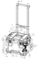
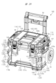
- FIG. 2 is a perspective view showing a structure of a case according to an embodiment of the present invention.
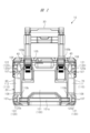
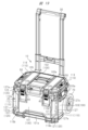
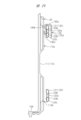
- FIG. 2 is a front view showing the structure of the case shown in FIG. 1 .
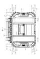
- FIG. 2 is a top view showing the structure of the case shown in FIG. 1 .
- FIG. 2 is a bottom view showing the structure of the case shown in FIG. 1 .
- FIG. 2 is a rear view showing the structure of the case shown in FIG. 1 .
- FIG. 2 is a right side view showing the structure of the case shown in FIG. 1 .
- FIG. 2 is a left side view showing the structure of the case shown in FIG. 1 .
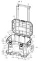
- 2 is a perspective view showing the structure of the case shown in FIG. 1 with a lid portion open.
- FIG. FIG. 1 is a front view showing the structure of the case shown in FIG. 1 .
- FIG. 2 is a top view showing the structure of the case shown in FIG. 1 .
- FIG. 2 is a bottom view showing the structure of the
- FIG. 2 is a partial perspective view showing an attachment structure of a hooking bar (hanging portion) in the case shown in FIG. 1 .
- 2 is a perspective view showing a structure in which a work machine is hooked onto a hooking bar in the case shown in FIG. 1 .
- 11 is a partial top view showing a range in which the work machine can be hung in the structure shown in FIG. 10 in which the work machine is hung.
- FIG. 2 is a perspective view showing a structure in which a hooking plate (rear-mounted hooking portion) is attached to a hooking bar in the case shown in FIG. 1 .
- FIG. 13 is a top view showing a structure in which the hooking plate shown in FIG. 12 is attached.
- FIG. 12 is a front view
- FIG. 12 is a top view
- FIG. 12 is a rear view
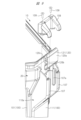
- 13A and 13B are diagrams showing the structure of the hooking bar shown in FIG. 12, in which FIG. FIG. 13 is a cross-sectional view showing a structure in which the hooking plate shown in FIG. 12 is attached.
- 13 is a perspective view showing a structure in which a working machine is hooked onto the hooking plate shown in FIG. 12 .
- FIG. 2 is a perspective view showing a structure in which a front hooking plate (rear-mounted hooking portion) is attached to a hooking bar in the case shown in FIG. 1 .
- 2 is a perspective view showing a structure in which a vertical hooking plate (rear-mounted hooking portion) is attached to a hooking bar in the case shown in FIG. 1 .
- 20 is a perspective view showing a structure in which an external hooking plate (rear-mounted hooking portion) is attached to the vertical hooking plate shown in FIG. 19 .
- FIG. 11 is a perspective view showing a structure of a case according to a first modified example of an embodiment of the present invention.
- FIG. 11 is a perspective view showing a structure of a case according to a first modified example of an embodiment of the present invention.
- FIG. 11 is a perspective view showing a structure of a case according to a second modified example of the embodiment of the present invention.
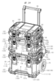
- FIG. 13 is a perspective view showing a stack structure of cases according to a third modified example of an embodiment of the present invention.
- FIG. 13 is a perspective view showing a locked state in the stack structure shown in the third modified example.
- 13 is a perspective view showing a state in which luggage is bound by a rubber band in the stack structure shown in the third modified example.
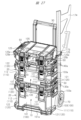
- FIG. FIG. 13 is a perspective view showing a state in which the stack structure shown in the third modified example is mounted on a vehicle.
- FIG. 13 is a perspective view showing a tool insertion state in the stack structure shown in the third modified example.
- FIG. 13 is a perspective view showing a structure of a case according to a fourth modified example of the embodiment of the present invention.
- FIG. 13 is a cross-sectional view showing a structure in which a hooking plate according to a fifth modified example of an embodiment of the present invention is attached.
- the case 10 in this embodiment is a box-shaped container capable of storing, for example, a work machine 60 such as an electric tool and accessories for the work machine 60 inside.
- the structure of the case 10 shown in Figs. 1 to 8 includes a box-shaped main body 20 having a plurality of side walls 100 and a bottom wall 106, and a lid 105 that covers an opening 20a provided on the upper surface of the main body 20.
- the case 10 is a substantially rectangular parallelepiped case 10. Therefore, the main body 20 has four side walls 100.
- the four side walls 100 include a front wall 101, a rear wall 102, a right wall 103, and a left wall 104.
- the bottom wall 106 and the four side walls 100 are each made of a thin plate member.
- the main body 20 consists of a bottom wall 106, a front wall 101, a rear wall 102, a right wall 103, and a left wall 104, and an opening 20a is formed on the top surface.
- the main body 20 is provided with a lid 105 capable of closing the opening 20a on the top surface.
- the lid 105 is provided on the upper end of the rear wall 102 of the main body 20 so as to be freely rotatable by a hinge or the like. Therefore, when an operator stores a work machine 60 (see FIG. 10 described later) or the like inside or removes the work machine 60 or the like from inside, the lid 105 is rotated to the open state as shown in FIG. 8.
- the main body 20 also has corners 110 that connect adjacent side walls 100 of the four side walls 100.
- the main body 20 has the corners 110 including a first corner 111, a second corner 112, a third corner 113, and a fourth corner 114.
- the first corner 111 connects the front wall 101 and the right wall 103
- the second corner 112 connects the front wall 101 and the left wall 104.
- the third corner 113 connects the rear wall 102 and the right wall 103
- the fourth corner 114 connects the rear wall 102 and the left wall 104.
- the case 10 of this embodiment is relatively large, so it is provided with tires that roll when transported so that it can be pulled while being transported. Specifically, as shown in Figs. 4 to 7, it has a right tire 70 that is rotatably mounted along the right wall 103, and a left tire 80 that is rotatably mounted along the left wall 104.
- Each tire has a portion that protrudes rearward from the rear wall 102 as shown in Figs. 6 and 7 so that the main body 20 does not rub against the ground when the case 10 is pulled while being transported. In other words, when an operator transports the case while pulling it, the main body 20 becomes slanted. At that time, a portion of each of the right tire 70 and the left tire 80 protrudes rearward from the rear wall 102, so that the lower part of the rear wall 102 can be prevented from rubbing against the ground.
- the case 10 is provided with a retractable main handle 30 that can be pulled during transportation.
- the main handle 30 is attached to the rear wall 102 and is retractable. Therefore, when pulling it for transportation, etc., the main handle 30 can be pulled out upward.
- the main handle 30 can be stored by shrinking it to a degree that it does not protrude above the lid portion 105.
- the front wall 101 is provided with a front bar 101a.
- the front bar 101a is provided along the left-right direction at the bottom of the front wall 101.
- the front bar 101a is used, for example, when pulling the case 10 mounted on the loading platform 170 (see Fig. 26 described later) of a truck or the like forward.
- a collapsible top handle 105a is attached to the lid 105.
- the top handle 105a is used by lifting the case 10. When not in use, it can be folded down and stored so that it does not protrude from the lid 105.
- a collapsible side handle 103a is attached to the right wall 103.
- a collapsible side handle 104a is also attached to the left wall 104.
- the side handles 103a, 104a are used by lifting the case 10 for carrying or pulling the case 10 out laterally. That is, when carrying a heavy case 10, the handles are grasped on both the left and right sides. Or, when pulling the case 10 out laterally, the handles are grasped and pulled out. When not in use, the handles can be folded down and stored so that they do not protrude from the right wall 103 or the left wall 104.
- the front wall 101 is provided with a latch 40.
- the latch 40 is attached to the right and left sides of the upper end of the front wall 101 so as to open and close in the vertical direction.
- the right and left sides of the front end of the lid 105 are provided with concave engagement parts 105b that can engage with the latch 40. This allows the closed lid 105 to be locked by rotating the latch 40 and fitting it into the engagement part 105b. Furthermore, the lock can be released by rotating the latch 40 downwards and disengaging it from the engagement part 105b, allowing the lid 105 to be opened.
- rotatable connecting hinges 50 are attached to the left and right ends of the lid 105.
- the case 10 is structured so that it can be stacked with other cases of a predetermined shape.
- the connecting hinges 50 can engage with protruding connecting portions 130a, 140a (see Figs. 21 and 22 described below) provided on the bottom wall 106 of the upper case.
- the connecting hinges 50 By fitting the connecting hinges 50 into the connecting portions 130a, 140a, the cases can be fixed together so that the upper case does not move when stacked.
- the case 10 of this embodiment is provided with a hooking bar 120 as a hooking portion at each of the four corners 110.
- the hooking bar 120 is a columnar metal member (bar) extending in a direction intersecting the vertical direction.
- the hooking bar 120 is formed of a metal flat plate-like member as shown in Fig. 9 described later.
- the hooking bar 120 is a metal flat plate-like member formed with a width D1 in the vertical direction larger than a thickness D2 in the thickness direction, and has a flat surface 120a (see Fig. 16). As shown in Fig.
- the hooking bar 120 is a member that can support a working machine 60 or an accessory of the working machine 60 by hooking the hook 60a, for example, in a working machine 60 equipped with a hook 60a or an accessory of the working machine 60.
- the hooking bar 120 is a flat metal member to increase its strength, but to reduce its mass and make it easier to manufacture, it may be made of a different material, such as resin, or may have a different shape, such as a pin with a circular cross section.
- the hooking bar 120 as described above is provided at each of the four corners 110.
- the hooking bar 120 includes a first hooking bar (first hook portion) 121 provided at the first corner 111 and extending in a direction intersecting the vertical direction, and a second hooking bar (second hook portion) 122 provided at the second corner 112 and extending in a direction intersecting the vertical direction.
- the hooking bar 120 includes a third hooking bar (third hook portion) 123 provided at the third corner 113 and extending in a direction intersecting the vertical direction, and a fourth hooking bar (fourth hook portion) 124 provided at the fourth corner 114 and extending in a direction intersecting the vertical direction.
- each hooking bar 120 is positioned so as not to overlap with the lid portion 105 when viewed in the vertical direction. Specifically, the hooking bar 120 is supported at each corner 110 by a rib 107 protruding from the main body portion 20 in FIG. 1. Each hooking bar 120 is supported by the rib 107 so that a gap 90 is formed between the main body portion 20 and the hooking bar 120. As a result, when viewed in the vertical direction of the main body portion 20, the hooking bar 120 is positioned along the surface of the corner portion 110 at a position protruding outward from the outline of the main body portion 20. Since a gap 90 is formed between the main body portion 20 and the hooking bar 120 in this way, a hook 60a of a work machine 60 or the like can be hooked onto the hooking bar 120.
- the hooking bars 120 are provided at the upper portion 110a and the lower portion 110b of the corner portion 110 of the main body portion 20.
- the hooking bars 120 are provided at the upper portion 110a and the lower portion 110b of the first corner portion 111 and the second corner portion 112 facing the front wall 101, respectively, as shown in Figs. 1 and 2.
- the right tire 70 and the left tire 80 are located at the third corner portion 113 and the fourth corner portion 114 facing the rear wall 102, and therefore the hooking bars 120 are provided only at the upper portion 110a.
- the case 10 has hooking bars 120 in six locations.
- the hooking bar 120 is supported by two ribs 107 provided at the corners 110 of the main body 20.
- the two ribs 107 protrude outward from the main body 20 at the corners 110.
- a notch 107a is formed in each of the ribs 107, and the hooking bar 120 is fitted into the notch 107a to be positioned.
- the hooking bar 120 is then fixed to the rib 107 by a piece member 108 that fits into the rib 107.
- the hooking bar 120 is fixed to the rib 107 by screwing the rib 107 and the piece member 108 together with a screw member 109.
- the screw member 109 is hidden by the lid 105 when viewed from above and below when the opening 20a on the top surface of the main body 20 shown in FIG. 8 is closed by the lid 105, as shown in FIG. 3. In other words, when the lid 105 is closed, the screw member 109 is hidden by the lid 105 and cannot be seen even when viewed from above. This improves the appearance of the case 10.
- the hooking bar 120 which is formed into a ring shape from a metal plate-like member, has a reinforcing bar 120b provided inside, so that it has high load-bearing capacity and will not collapse even if a heavy work machine 60 is hooked onto it.
- a hooking bar 120 is provided at the corner 110 of the main body 20, and the hooking bar 120 is disposed at a position where it does not overlap with the lid 105 when viewed in the vertical direction, that is, at a position protruding outward from the outline of the main body 20. Furthermore, since a gap 90 is formed between the main body 20 and the hooking bar 120, as shown in FIG. 11, by hooking the hook 60a on the hooking bar 120, as shown in FIG. 10, the working machine 60 and the accessories of the working machine 60 can be hooked on the hooking bar 120. In addition, since the hooking bar 120 is formed in a flat shape with a vertical width D1 larger than a thickness D2 in the thickness direction (see FIG. 16), the hook 60a is prevented from rotating around the hooking bar 120.
- the hooking bar 120 is provided at the corner 110 of the main body 20 and is arranged at a position protruding from the main body 20.
- the first hooking bar 121 is provided outside the virtual line M1 connecting the right end 101b of the front wall 101 and the front end 103b of the right wall 103 when viewed in the up-down direction.
- the hooking bar 120 can be attached with a hooking plate (rear-attached hooking portion) 125 that bridges and hooks the hooking bars 120 provided at adjacent corners 110 among the multiple corners 110.
- the hooking plate 125 is formed of a long and thin metal plate material, and has a shape that can bridge and hook, for example, the first hooking bar 121 at the first corner 111 and the third hooking bar 123 at the third corner 113.
- the hooking plate 125 is formed by bending a metal plate as shown in Figs.
- hook portions 125b that can be hooked onto the hooking bars 120 are formed on both ends of the plate body 125a. By hooking the hook portions 125b on both ends onto the hooking bars 120, the hooking plate 125 can be attached by bridging the hooking bars 120 provided on the adjacent corners 110.
- the hook portion 125b of the hooking plate 125 includes a U-shaped portion 125c that hooks onto the hooking bar 120, and a return portion (protrusion) 125d that extends downward from the U-shaped portion 125c and protrudes toward the inside of the U-shaped portion 125c to abut against the hooking bar 120. That is, the hook portion 125b includes the U-shaped portion 125c and the return portion 125d.
- the hook portion 125b of the hooking plate 125 is provided with the return portion 125d, so that when the hook portion 125b is fitted from above the hooking bar 120, the hook portion 125b is positioned and the hook portion 125b is prevented from coming off upward.
- FIG. 17 shows a structure in which a working machine 60 is hooked to the hooking plate 125.
- the gap 91 (see FIG. 13) between the plate body 125a of the hooking plate 125 and the main body 20 has, for example, a width D3 of 20 mm and a length D4 of 100 mm.
- the width D3 may be 5 mm or more and 30 mm or less
- the length D4 may be 20 mm or more and 150 mm or less, which makes it possible to hook the working machine 60 to the hooking plate 125 attached to the main body 20.
- the hooking plate 125 can be prevented from twisting outward due to the weight of the working machine 60. In other words, the hooking plate 125 can be prevented from moving upward relative to the hooking bar 120 and falling off.
- the hooking plate 125 has a partition portion 125e that partitions the hooking plate 125 in the extension direction of the hooking plate 125 (the direction along the front-rear direction in the case 10 in Fig. 13) and protrudes toward the main body portion 20 of the case 10 in Fig. 1.
- the partition portion 125e protrudes toward the main body portion 20 and is provided so as to be able to abut against the main body portion 20 when attached to the hooking bar 120 (abutment portion P2).
- the partition portion 125e abuts against the main body portion 20, so that the hooking plate 125 can be prevented from breaking or deforming.
- the partition portion 125e has an insertion hole 125f so that an elongated tool such as a screwdriver 173 can be inserted as shown in Fig. 27.
- partitions 125e are provided at three locations at desired intervals in the extension direction of the plate body 125a of the hooking plate 125. This allows the working machine 60 and its accessories to be hooked separately to the hooking plate 125. For example, when the case 10 in the state shown in FIG. 12 is transported by pulling its main handle 30, the case 10 tilts. At that time, since the working machine 60 and accessories are hooked to the location partitioned by the partitions 125e in the hooking plate 125, even if the case 10 tilts and the hooking plate 125 becomes slanted, it is possible to suppress the working machine 60 and accessories from being biased to one side, and to reduce the working machine 60 and accessories from slipping off.
- the hooking plate 125 is not limited to a long and thin metal plate material, but may be made of resin, and may have a box-shaped storage section to store the working machine 60 and its accessories.
- FIG 18 is a diagram showing a structure in which a front hooking plate (rear-mounted hooking portion) 126 is attached to the hooking bar 120 in the case 10. That is, the front hooking plate 126 is attached by hooking the hook portions 126a at both ends to the hooking bar 120 at the upper portion 110a of the first corner portion 111 on the front side and the hooking bar 120 at the upper portion 110a of the second corner portion 112. This makes it possible to hook and support the work machine 60 and its accessories shown in Figure 17 on the front hooking plate 126 as well.
- the front hooking plate 126 also has partition portions 126b at multiple locations, which can provide the same effect as the partition portion 125e of the hooking plate 125.
- FIG. 19 is a diagram showing a structure in which a vertical hooking plate (rear-mounted hooking portion) 127 is attached to the hooking bar 120 in the case 10. That is, the vertical hooking plate 127 is attached in the vertical direction by hooking the hook portions 127a at both ends to the hooking bar 120 at the upper portion 110a of the first corner portion 111 on the front side and the hooking bar 120 at the lower portion 110b of the first corner portion 111. This allows the vertical hooking plate 127 to support even more working machines 60, and the vertical hooking plate 127 can also be used as a bumper to protect the corner portion 110. In order to increase the strength of the vertical hooking plate 127 when used as a bumper, a cushioned protective member such as an elastic body may be provided on the surface of the vertical hooking plate 127. .
- Figure 20 is a diagram showing a structure in which an external hooking plate (rear-mounted hooking portion) 128 is attached to the vertical hooking plate 127 shown in Figure 19. That is, the external hooking plate 128 is attached in the left-right direction by hooking the hook portions 128a at both ends to the vertical hooking plate 127 attached to the first corner 111 and the vertical hooking plate 127 attached to the second corner 112. This makes it possible to hook and support the work machine 60 and its accessories shown in Figure 17 to the external hooking plate 128 as well.
- an external hooking plate rear-mounted hooking portion
- the case 130 of the first modified example shown in FIG. 21 has a structure with a lower vertical height than the case 10 shown in FIG. 1. Therefore, the case 130 does not have the retractable main handle 30 on the rear wall 102 side and the right tire 70 and left tire 80 provided in the case 10 of FIG. 1.
- the hooking bars 120 are provided at the upper part 110a and the lower part 110b of each of the four corners 110 of the first corner 111, the second corner 112, the third corner 113, and the fourth corner 114. That is, in the case 130, the hooking bars 120 are provided at the upper and lower sides of each of the four corners 110, and a total of eight hooking bars 120 are provided. Therefore, the working machine 60 and its accessories can be hooked to the hooking bars 120 provided at any of the corners 110.
- hooking the hook portion 125b and the hook portion 126a to the hooking bar 120 at the corner 110 it is possible to attach the hooking plate 125 and the front hooking plate 126 to the front wall 101, the rear wall 102, the right wall 103, and the left wall 104, and it is also possible to attach the vertical hooking plate 127 to each corner 110.
- the case 130 also has a protruding connecting portion 130a on its bottom wall 106. This allows it to be stacked on the case 10 shown in FIG. 20.
- the case 140 of the second modified example shown in FIG. 22 has a structure in which the height in the vertical direction is even lower than that of the case 130 shown in FIG. 21. Therefore, the case 140 does not have the retractable main handle 30 on the rear wall 102 side and the right tire 70 and left tire 80 provided on the case 10 in FIG. 1. And, because the height in the vertical direction is low, one hooking bar 120 is provided at each of the four corners 110, the first corner 111, the second corner 112, the third corner 113, and the fourth corner 114. That is, in the case 140, one hooking bar 120 is provided at each of the four corners 110, for a total of four hooking bars 120.
- the hooking bar 120, the hooking plate 125, and the front hooking plate 126 can be hooked and supported with the work machine 60 and its accessories.
- a front handle 140b is provided on the front wall 101 of the case 140.
- the case 140 also has a protruding connecting portion 140a at the bottom of the side wall 100. This allows it to be stacked on top of the case 10 shown in FIG. 20 or the case 130 shown in FIG. 21.
- the third modified example shown in FIG. 23 shows an example of a stack structure.
- Case 10 shown in FIG. 1 is placed in the lowest tier
- case 130 shown in FIG. 21 is stacked in the second tier above that
- case 140 shown in FIG. 22 is stacked in the third tier above that, resulting in a stack structure.
- the lid 105 of each of the cases 10, 130, and 140 is provided with a connecting hinge 50. Furthermore, the lower portion of each side wall 100 of the stacked cases 130 and 140 is provided with a protruding connecting portion 130a, 140a. Therefore, by engaging the connecting portion 130a, 140a of each of the upper cases 130 and 140 with the connecting hinge 50 of each of the lower cases 10, 130, and 140 (fitting the connecting hinge 50 on the lower side into the connecting portion 130a, 140a on the upper side), the cases can be fixed together so that the upper cases 130 and 140 do not move when stacked.
- the working machine 60 and its accessories can be hooked and supported on the hooking bars 120 provided on each of the cases 10, 130, and 140.
- the hooking plates 125 and front hooking plates 126 can be attached to the hooking bars 120 provided on the corners 110 of each of the cases 10, 130, and 140, and the working machine 60 and its accessories can be hooked and supported on these hooking plates 125 and front hooking plates 126.
- a vertical hooking plate 127 can be attached to the cases 10 and 130, thereby increasing the strength of the cases 10 and 130 in the vertical direction.
- the case 10 is placed at the bottom of the stack structure, and the case 10 is provided with a retractable main handle 30 on the rear wall 102 side, a right tire 70, and a left tire 80. Therefore, even with a three-tier stack structure, for example, an operator can transport the cases 10, 130, and 140 by pulling the extended main handle 30.
- the stack structure shown in FIG. 24 is constructed by passing a rope 150 through the hooking bar 120 of each of the cases 10, 130, and 140, and connecting both ends of the rope 150 with a lock 151 such as a padlock.
- the hooking bar 120 has a gap 90 (see FIG. 3) on the lower side between it and the main body 20, so the rope 150 can be passed from the top to the bottom of the hooking bar 120.
- the cases 10, 130, and 140 stacked in three tiers are connected by the rope 150, and the rope 150 is connected with a lock 151, so the theft of the stacked cases 10, 130, and 140 can be prevented.
- the stack structure shown in FIG. 25 shows a structure in which luggage 160 is placed on the top case 140 of the stacked cases 10, 130, 140 and secured to the case 140.
- luggage 160 is placed on the lid 105 of the top case 140, and rubber bands 161 are hooked between the hooking bars 120 of the diagonally arranged cases 140, and luggage 160 is secured to the case 140 by the rubber bands 161 running diagonally.
- This allows an operator to transport the cases 10, 130, 140 and luggage 160 by pulling the main handle 30, with luggage 160 secured to the top case 140 of the three stacked cases 10, 130, 140.
- the stack structure shown in FIG. 26 secures cases 10, 130, and 140 stacked in three tiers to, for example, the bed 170 of a truck, using belts 171.
- belts 171 are fastened to four hooking bars 120 on the top case 140, and these four belts 171 are each connected to hooks 172 on the bed 170.
- the hooking bars 120 are also suitable for belt fastening, and this allows the cases 10, 130, and 140 stacked in three tiers to be transported while firmly secured to the bed 170 of a truck, etc.
- the stack structure shown in FIG. 27 has a hooking plate 125 attached to the hooking bar 120 of the top case 140, and a long object such as a screwdriver 173 or a wide tool such as a ruler 174 can be inserted and supported in the gap 91 (see FIG. 13) between the hooking plate 125 and the main body 20.
- the gap 91 is about 20 mm, which is a suitable size for inserting or hanging tools such as the screwdriver 173 and ruler 174 that are used frequently by workers.
- the fourth modified example shown in FIG. 28 shows a case 180 in which the hooking bars 120 at the first corner 111 and the second corner 112 are provided in three stages, the upper stage, the middle stage, and the lower stage. That is, in the case 180, the hooking bars 120 are provided at the upper stage 110a, the lower stage 110b, and the middle stage 110c between the upper stage 110a and the lower stage 110b at the first corner 111 and the second corner 112. That is, the hooking bars 120 may be provided in two or more stages at the corners 110 of the main body 20.
- the hooking bar 120 may be provided at any corner 110 of the main body 20.
- the fifth modified example shown in FIG. 29 shows a modified shape of the hook portion 190a of the hooking plate 125 attached to the hooking bar 120.
- the hook portion 190a has a U-shaped portion 190b that hooks onto the hooking bar 120, and also has a return portion (protrusion) 190c that extends downward from the U-shaped portion 190b and protrudes toward the inside of the U-shaped portion 190b so as to be able to abut against the hooking bar 120.
- the shape of the return portion 190c of the hook portion 190a is a shape that follows the recess 120c on the inside of the hooking bar 120 and is a shape that abuts against the recess 120c.
- the hook portion 190a is less likely to come off the hooking bar 120, and the hooking plate 125 is less likely to come off the hooking bar 120.
- the stack structure is described as being in a three-tiered state, but the number of tiers of stacked cases may be two, or may be three or more tiers.
- extension direction of the columnar hook portion does not necessarily have to be perpendicular to the vertical direction, as long as it is a direction that intersects with the vertical direction.
- middle part 111... first corner, 112... second corner, 113... third corner, 114... fourth corner, 120... hooking bar (hooking part), 120a... flat surface, 120b... reinforcing bar, 120c... recess, 121... first hooking bar (first hooking part), 122... second hooking bar (second hooking part), 123...
Landscapes
- Engineering & Computer Science (AREA)
- Mechanical Engineering (AREA)
- Fittings On The Vehicle Exterior For Carrying Loads, And Devices For Holding Or Mounting Articles (AREA)
- Packaging Of Machine Parts And Wound Products (AREA)
Abstract
Description
Claims (11)
- 複数の側壁と、底壁と、を有する箱状の本体部と、
前記本体部の上面に設けられる開口を覆う蓋部と、を有し、
前記複数の側壁は、前壁、後壁、右壁及び左壁を含み、
前記複数の側壁のうち隣り合う側壁同士を接続する複数の角部と、
前記角部に設けられ、上下方向と交差する方向に延びる柱状の引掛部と、
を備え、
前記引掛部は、上下方向視において、前記蓋部と重ならない位置に配置される、ケース。 - 前記角部は、
前記前壁と前記右壁とを接続する第1角部と、
前記前壁と前記左壁とを接続する第2角部と、
前記後壁と前記右壁とを接続する第3角部と、
前記後壁と前記左壁とを接続する第4角部と、
を含み、
前記引掛部は、
前記第1角部に設けられ、上下方向と交差する方向に延びる第1引掛部と、
前記第2角部に設けられ、上下方向と交差する方向に延びる第2引掛部と、
前記第3角部に設けられ、上下方向と交差する方向に延びる第3引掛部と、
前記第4角部に設けられ、上下方向と交差する方向に延びる第4引掛部と、
を有する、請求項1に記載のケース。 - 前記第1引掛部は、上下方向視において、前記前壁の右端部と前記右壁の前端部とを結ぶ仮想線よりも外側に設けられる、請求項2に記載のケース。
- 前記引掛部は、前記角部の上部と下部とに設けられる、請求項1に記載のケース。
- 前記引掛部は、前記第1及び第2角部において、それぞれの前記角部の上部と下部とに設けられる、請求項2に記載のケース。
- 前記引掛部は、金属製の平板状部材によって形成される、請求項1に記載のケース。
- 前記引掛部は、前記本体部の複数の前記角部に設けられ、
前記引掛部は、前記複数の角部のうちの隣り合う前記角部に設けられた前記引掛部に橋渡しして引っ掛ける後付引掛部を取り付け可能である、請求項1に記載のケース。 - 前記後付引掛部は、前記引掛部に引っ掛けるU字状部を備えるとともに、前記U字状部から下方に向けて延在し、かつ前記U字状部の内側に向けて突出して前記引掛部に当接可能な突出部を備える、請求項7に記載のケース。
- 前記後壁より後方に突出する部分を有し、前記右壁に沿って回転可能に設けられる右側タイヤと、
前記後壁より後方に突出する部分を有し、前記左壁に沿って回転可能に設けられる左側タイヤと、
を備え、
前記後付引掛部は、前記後付引掛部の延在方向において前記後付引掛部を仕切るとともに、前記本体部に向けて突出する仕切部を有する、請求項7に記載のケース。 - 前記角部に前記本体部の外側に突出するとともに、切欠部を備えるリブが設けられ、
前記引掛部は、前記切欠部に嵌め込まれ、
前記引掛部は、前記リブと嵌合する駒部材によって前記リブに固定される、請求項1に記載のケース。 - 前記引掛部は、前記リブと前記駒部材とがねじ部材によってねじ結合されることで前記リブに固定され、
前記ねじ部材は、前記本体部の上面の開口が前記蓋部によって閉じられた状態の上下方向視において、前記蓋部によって隠される、請求項10に記載のケース。
Priority Applications (2)
| Application Number | Priority Date | Filing Date | Title |
|---|---|---|---|
| CN202380058774.7A CN119677619A (zh) | 2022-09-30 | 2023-09-07 | 壳体 |
| JP2024549960A JPWO2024070559A1 (ja) | 2022-09-30 | 2023-09-07 |
Applications Claiming Priority (2)
| Application Number | Priority Date | Filing Date | Title |
|---|---|---|---|
| JP2022-157972 | 2022-09-30 | ||
| JP2022157972 | 2022-09-30 |
Publications (1)
| Publication Number | Publication Date |
|---|---|
| WO2024070559A1 true WO2024070559A1 (ja) | 2024-04-04 |
Family
ID=90477378
Family Applications (1)
| Application Number | Title | Priority Date | Filing Date |
|---|---|---|---|
| PCT/JP2023/032639 Ceased WO2024070559A1 (ja) | 2022-09-30 | 2023-09-07 | ケース |
Country Status (3)
| Country | Link |
|---|---|
| JP (1) | JPWO2024070559A1 (ja) |
| CN (1) | CN119677619A (ja) |
| WO (1) | WO2024070559A1 (ja) |
Citations (3)
| Publication number | Priority date | Publication date | Assignee | Title |
|---|---|---|---|---|
| JPS4971493U (ja) * | 1972-10-07 | 1974-06-21 | ||
| JPH033188Y2 (ja) * | 1984-07-09 | 1991-01-28 | ||
| JP3191058U (ja) * | 2014-03-26 | 2014-06-05 | グローブライド株式会社 | プライヤ等ホルダ |
-
2023
- 2023-09-07 JP JP2024549960A patent/JPWO2024070559A1/ja active Pending
- 2023-09-07 CN CN202380058774.7A patent/CN119677619A/zh active Pending
- 2023-09-07 WO PCT/JP2023/032639 patent/WO2024070559A1/ja not_active Ceased
Patent Citations (3)
| Publication number | Priority date | Publication date | Assignee | Title |
|---|---|---|---|---|
| JPS4971493U (ja) * | 1972-10-07 | 1974-06-21 | ||
| JPH033188Y2 (ja) * | 1984-07-09 | 1991-01-28 | ||
| JP3191058U (ja) * | 2014-03-26 | 2014-06-05 | グローブライド株式会社 | プライヤ等ホルダ |
Also Published As
| Publication number | Publication date |
|---|---|
| CN119677619A (zh) | 2025-03-21 |
| JPWO2024070559A1 (ja) | 2024-04-04 |
Similar Documents
| Publication | Publication Date | Title |
|---|---|---|
| US11738444B2 (en) | Storage chest with secondary storage compartment | |
| JP2024539496A (ja) | 収納ボックスの連結性を備えたモジュール式収納システム、外部ボックス構成および付属品、ならびに、内部収納および蓋構成 | |
| EP4124586B1 (en) | Electric vehicle battery transportation container | |
| US9399434B2 (en) | Fencing repair and cargo toolbox | |
| US20070039957A1 (en) | Storage containers for vehicles | |
| US8240732B2 (en) | Trailer utility box | |
| US6604897B2 (en) | Vinyl siding transport rack and method of construction | |
| US10793051B2 (en) | Cable for securing cargo in vehicles with a locking tailgate | |
| US20050236788A1 (en) | Combination tool box and dolly | |
| WO2024070559A1 (ja) | ケース | |
| US11986945B2 (en) | Work site lid hanger storage system | |
| US20030085142A1 (en) | Equipment caddy | |
| US20070194071A1 (en) | Configurable vehicle storage system and method of use | |
| JP7426325B2 (ja) | 貨物自動車荷台用システムフロアおよびシステムフロアセット | |
| JP6473678B2 (ja) | 荷室仕切り構造 | |
| JP4567874B2 (ja) | 組立容器 | |
| JP3180160U (ja) | 細長い荷物用通函 | |
| JP2000128160A (ja) | 梱包用コンテナ | |
| KR20090006609U (ko) | 카트형 이동식 인양공기구 보관장치 | |
| US20080099355A1 (en) | Tool Bag Assembly | |
| CN223303328U (zh) | 一种侧进式轻钢包装箱 | |
| KR102038824B1 (ko) | 수납함이 구비된 유리 이송용 파렛트 | |
| ITTO20030143U1 (it) | Contenitore modificato per spedizione marittima | |
| JP4567873B2 (ja) | 組立容器 | |
| JP2025080710A (ja) | 建築現場における工具類携行システム |
Legal Events
| Date | Code | Title | Description |
|---|---|---|---|
| 121 | Ep: the epo has been informed by wipo that ep was designated in this application |
Ref document number: 23871798 Country of ref document: EP Kind code of ref document: A1 |
|
| WWE | Wipo information: entry into national phase |
Ref document number: 202380058774.7 Country of ref document: CN |
|
| WWE | Wipo information: entry into national phase |
Ref document number: 2024549960 Country of ref document: JP |
|
| WWP | Wipo information: published in national office |
Ref document number: 202380058774.7 Country of ref document: CN |
|
| NENP | Non-entry into the national phase |
Ref country code: DE |
|
| 122 | Ep: pct application non-entry in european phase |
Ref document number: 23871798 Country of ref document: EP Kind code of ref document: A1 |