WO2024070546A1 - ダンパ装置 - Google Patents
ダンパ装置 Download PDFInfo
- Publication number
- WO2024070546A1 WO2024070546A1 PCT/JP2023/032547 JP2023032547W WO2024070546A1 WO 2024070546 A1 WO2024070546 A1 WO 2024070546A1 JP 2023032547 W JP2023032547 W JP 2023032547W WO 2024070546 A1 WO2024070546 A1 WO 2024070546A1
- Authority
- WO
- WIPO (PCT)
- Prior art keywords
- friction
- target member
- friction member
- plate
- rotating body
- Prior art date
- Legal status (The legal status is an assumption and is not a legal conclusion. Google has not performed a legal analysis and makes no representation as to the accuracy of the status listed.)
- Ceased
Links
Images





Classifications
-
- F—MECHANICAL ENGINEERING; LIGHTING; HEATING; WEAPONS; BLASTING
- F16—ENGINEERING ELEMENTS AND UNITS; GENERAL MEASURES FOR PRODUCING AND MAINTAINING EFFECTIVE FUNCTIONING OF MACHINES OR INSTALLATIONS; THERMAL INSULATION IN GENERAL
- F16D—COUPLINGS FOR TRANSMITTING ROTATION; CLUTCHES; BRAKES
- F16D7/00—Slip couplings, e.g. slipping on overload, for absorbing shock
- F16D7/02—Slip couplings, e.g. slipping on overload, for absorbing shock of the friction type
-
- F—MECHANICAL ENGINEERING; LIGHTING; HEATING; WEAPONS; BLASTING
- F16—ENGINEERING ELEMENTS AND UNITS; GENERAL MEASURES FOR PRODUCING AND MAINTAINING EFFECTIVE FUNCTIONING OF MACHINES OR INSTALLATIONS; THERMAL INSULATION IN GENERAL
- F16F—SPRINGS; SHOCK-ABSORBERS; MEANS FOR DAMPING VIBRATION
- F16F15/00—Suppression of vibrations in systems; Means or arrangements for avoiding or reducing out-of-balance forces, e.g. due to motion
- F16F15/10—Suppression of vibrations in rotating systems by making use of members moving with the system
- F16F15/12—Suppression of vibrations in rotating systems by making use of members moving with the system using elastic members or friction-damping members, e.g. between a rotating shaft and a gyratory mass mounted thereon
- F16F15/131—Suppression of vibrations in rotating systems by making use of members moving with the system using elastic members or friction-damping members, e.g. between a rotating shaft and a gyratory mass mounted thereon the rotating system comprising two or more gyratory masses
- F16F15/139—Suppression of vibrations in rotating systems by making use of members moving with the system using elastic members or friction-damping members, e.g. between a rotating shaft and a gyratory mass mounted thereon the rotating system comprising two or more gyratory masses characterised by friction-damping means
Definitions
- the technology disclosed in this application relates to a damper device that is disposed between a drive source and a transmission and absorbs torque fluctuations that occur between the drive source and the transmission.
- Patent Document 1 Patent Publication No. 4,581,576
- the damper device disclosed in Patent Document 1 includes a retaining plate that receives power from a drive source and rotates around a central axis, a damper mechanism that rotates around the central axis by engaging with the retaining plate via a friction member or the like, and a hub that rotates around the central axis and is provided with a coil spring sandwiched between the hub and the damper mechanism.
- the friction member that functions as the limiter material is adhered to both sides of a disk (i.e., a holding member that holds the friction member) included in the damper mechanism using an adhesive.
- a disk i.e., a holding member that holds the friction member
- Patent Document 1 it is also known that such a friction member can be fixed to the holding member using caulking or rivets. The entire contents of Patent Document 1 are incorporated herein by reference.
- the technology disclosed in this application provides a damper device in which a friction member serving as a limiter material is fixed to a retaining member using an improved method.
- the damper device may be configured to include a first rotating body that rotates around a rotating shaft when power from a drive source is transmitted to it, a second rotating body that engages with the first rotating body via a friction member and rotates around the rotating shaft when power is transmitted from the first rotating body, a third rotating body that rotates around the rotating shaft relative to the second rotating body, and an elastic mechanism that is arranged between the second rotating body and the third rotating body along the circumferential direction and expands or contracts, a first target member included in the first rotating body and a second target member included in the second rotating body are arranged with the friction member sandwiched between the first target member and the second target member, one of the first target member and the second target member is rotatably provided from a first position where it is rotatable relative to the friction member to a second position where it is fixed relative to the friction member, and the other of the first target member and the second target member is slidably provided on the friction member.
- the technology disclosed in this application makes it possible to provide a damper device in which a friction member serving as a limiter material is fixed to a retaining member using an improved method.
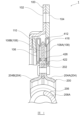
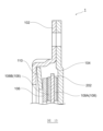
- FIG. 1 is a cross-sectional view that illustrates a schematic configuration of a portion of a damper device according to an embodiment.
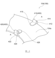
- FIG. 2 is a perspective view that diagrammatically illustrates a configuration of a portion of the first friction plate 104 (second friction plate 106) included in the damper device 1 shown in FIG.
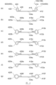
- FIG. 3 is a cross-sectional view showing a schematic configuration of the first friction plate 104 (second friction plate 106) shown in FIG. 2, taken along the line AA.
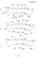
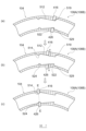
- 4(a) and 4(b) are top views that typically show the configuration of the first friction plate 104 (second friction plate 106) shown in FIG. 2
- FIG. 4(c) is a perspective view that typically shows the configuration of a portion of the first friction plate 104 (second friction plate 106) shown in FIG.
- FIG. 5 is a top view that diagrammatically illustrates a configuration of a portion of the first friction plate 104 (second friction plate 106) illustrated in FIG.
- FIG. 6 is a top view that diagrammatically illustrates the configuration of a portion of the friction member 108 included in the damper device 1 shown in FIG.
- FIG. 7 is a diagram illustrating a schematic diagram of an operation performed between the first friction plate 104 (the second friction plate 106) and the first friction member 108A (the second friction member 108B) included in the damper device shown in FIG.
- FIG. 8 is a cross-sectional view showing a schematic configuration of the first friction plate 104 and the first friction member 108A as viewed from the cross section EE shown in FIG. 7(c).
- FIG. 7 is a diagram illustrating a schematic diagram of an operation performed between the first friction plate 104 (the second friction plate 106) and the first friction member 108A (the second friction member 108B) included in the damper device shown in FIG.
- FIG. 8 is
- FIG. 9 is a top view that diagrammatically illustrates a portion of the configuration included in the damper device 1 shown in FIG.
- FIG. 10 is a perspective view that diagrammatically illustrates a configuration of a portion of the first friction plate 104 (second friction plate 106) illustrated in FIG.
- FIG. 11 is a perspective view showing another example of the first engagement portion 610 and the second engagement portion 620 included in the damper device 1 shown in FIG.
- FIG. 12 is a perspective view showing still another example of the first engagement portion 610 and the second engagement portion 620 included in the damper device 1 shown in FIG.
- FIG. 13 is a top view that diagrammatically illustrates another example of the damper device 1 shown in FIG. FIG.
- FIG. 14 is a perspective view that diagrammatically illustrates a configuration of a portion of the first friction plate 104 (second friction plate 106) illustrated in FIG.
- FIG. 15 is a cross-sectional view that diagrammatically shows another example of the damper device 1 shown in FIG.
- Fig. 1 is a cross-sectional view showing a schematic configuration of a part of a damper device according to an embodiment.
- a damper device 1 can be disposed between a driving source (e.g., an engine or a motor) (not shown) and a transmission (not shown).
- a driving source e.g., an engine or a motor
- a transmission not shown
- the damper device 1 can roughly include a first rotating body 100 that receives driving force from a driving source and rotates around a rotation axis, and a second rotating body 200 that receives power from the first rotating body 100 via a friction member 108 and rotates around the rotation axis.
- the damper device 1 may further include a third rotating body (hub) that rotates around a rotation axis relative to the second rotating body 200.
- This third rotating body (not shown) may be disposed above or below the second rotating body 200 on the paper in FIG. 1.
- the rotation axis (central axis) of this third rotating body may coincide with the rotation axes (central axes) of the first rotating body 100 and the second rotating body.
- the first rotating body 100 may include a retaining plate 102 , a first friction plate (first pressure plate) 104 , a second friction plate (second pressure plate) 106 , a friction member 108 , and a disc spring 110 .
- the retaining plate 102 to which power is transmitted from a driving source (not shown), can have a generally annular shape as a whole.
- the retaining plate 102 can be configured so that the outer circumferential portion abuts against the first friction plate 104 and is fixed by rivets (not shown) or the like, and the portion adjacent to the outer circumferential portion on the radially inward side ensures an accommodation space with a distance between the retaining plate 102 and the first friction plate 104.
- the second friction plate 106, the friction member 108, the disc spring 110, etc. can be accommodated in this accommodation space.
- the first friction plate 104 may have a generally annular shape overall, and may be made of a material such as hot-rolled steel plate (SPH) or stainless steel plate (SUS). As described above, the first friction plate 104 may be fixed to the retaining plate 102 by a rivet or the like (not shown). The first friction plate 104 may abut against the first friction member 108A of the friction members 108 to retain the first friction member 108A. The specific configuration of the first friction plate 104 will be described later.
- SPH hot-rolled steel plate
- SUS stainless steel plate
- the second friction plate 106 may have a generally annular shape as a whole, and may be made of a material such as hot-rolled steel plate (SPH) or stainless steel plate (SUS).
- the second friction plate 106 may be provided facing the first friction plate 104 so as to sandwich the friction members 108 (specifically, the first friction member 108A and the second friction member 108B) between the second friction plate 106 and the first friction plate 104.
- the second friction plate 106 may abut against the second friction member 108B of the friction members 108 to hold the second friction member 108B.
- the specific configuration of the second friction plate 106 will be described later.
- the friction member 108 may include two friction members 108A and 108B, each of which has a generally annular shape.
- Each of the friction members 108A and 108B may be formed from a commonly known material (e.g., cork mold, rubber mold, paper base, glass yarn, semi-metallic, etc.).
- the friction members 108A and 108B may be held by the first friction plate 104 and the second friction plate 106, respectively.
- a lining plate 202 (described later) of the second rotating body 200 may be disposed between these friction members 108A and 108B.
- the coned disc spring 110 can have a generally annular shape overall, and can be made of a material such as stainless steel (SUS).
- the coned disc spring 110 is arranged so that it abuts against the retaining plate 102 near its outer periphery and abuts against the second friction plate 106 near its inner periphery.
- the coned disc spring 110 can bias the second friction plate 106 in a direction toward the first friction plate 104.
- the second rotating body 200 may include a lining plate 202 , a side plate 204 , and an elastic mechanism portion 206 .
- the lining plate 202 may have a generally annular shape overall, and may be formed from a material such as hot-rolled steel plate (SPH) or stainless steel plate (SUS).
- the lining plate 202 may be sandwiched near its outer periphery between the first friction member 108A and the second friction member 108B of the first rotating body 100 described above. This allows the second rotating body 200 including the lining plate 200 to rotate around the rotation axis by engaging with the first rotating body 100 via the friction member 108 and receiving power from the first rotating body 100.
- the lining plate 202 can be fixed to the side plate 204 near its inner periphery by rivets or the like.
- the side plate 204 may include two side plates, namely a first side plate 204A and a second side plate 204B.
- Each side plate 204A, 204B may have a generally annular shape as a whole.
- the side plates 204A, 204B can be fixed to each other at the outer periphery with rivets or the like, with the lining plate 202 sandwiched between them. Also, the side plates 204A, 204B can form storage areas spaced apart from each other at adjacent portions radially inward from the outer periphery. The elastic mechanism 206 and the like can be housed in these storage areas.
- the elastic mechanism 206 can include at least one set of mechanisms including an elastic body (coil spring) 206A and a sheet (not shown) or the like that is disposed on both ends of the elastic body 206 and supports the elastic body 206. Although not shown, such an elastic mechanism 206 can be disposed between the second rotating body 200 (side plate 204 included in the second rotating body) and the third rotating body (hub) along the circumferential direction.
- the third rotating body (hub) (not shown) may be generally annular in shape.
- the third rotating body may include at least one flange portion (not shown) extending radially outward from its central portion.
- the third rotating body receives power from the second rotating body 200 via an elastic mechanism portion 206 arranged circumferentially between the flange portion and the side plate 204 of the second rotating body 200.
- the third rotating body can rotate relatively to the second rotating body around the rotation axis by expanding or contracting the elastic mechanism portion 206.
- the third rotating body is fixed to the input shaft of the transmission (not shown) which is inserted through its center, allowing it to transmit power to the transmission.
- the general operation of the damper device 1 including the above-described configuration is as follows. When power is transmitted from a drive source (not shown) to the holding plate 102, the first rotating body 100 including the holding plate 102 can rotate about a rotation axis.
- the rotational torque transmitted to the lining plate 202 is transmitted to the third rotating body (hub) via the side plate 204 and the elastic mechanism 206. This allows the third rotating body (hub) to rotate while the elastic mechanism 206 expands or contracts according to the fluctuating torque. As the third rotating body (hub) rotates in this manner, power is transmitted to a transmission (not shown).
- the first friction member 108A may be provided rotatably relative to the first friction plate 104. Thereafter, when the damper device 1 is used for the first time, the first friction member 108A may be fixed to the first friction plate 104. Thereby, the first friction member 108A can rotate integrally with the first friction plate 104 thereafter.
- the second friction member 108B can be provided rotatably relative to the second friction plate 106. Thereafter, when the damper device 1 is used for the first time, the second friction member 108B can be fixed to the second friction plate 106. Thereby, the second friction member 108B can rotate integrally with the second friction plate 106 thereafter.
- FIG. 2 is a perspective view showing a schematic configuration of a portion of the first friction plate 104 (second friction plate 106) included in the damper device 1 shown in FIG. 1.
- FIG. 3 is a cross-sectional view showing a schematic configuration of the first friction plate 104 (second friction plate 106) shown in FIG. 2 as seen from the A-A section.
- FIGS. 4(a) and 4(b) are top views showing a schematic configuration of the first friction plate 104 (second friction plate 106) shown in FIG. 2
- FIG. 4(c) is a perspective view showing a schematic configuration of a portion of the first friction plate 104 (second friction plate 106) shown in FIG. 2.
- FIG. 1 is a perspective view showing a schematic configuration of a portion of the first friction plate 104 (second friction plate 106) included in the damper device 1 shown in FIG. 1.
- FIG. 3 is a cross-sectional view showing a schematic configuration of the first friction plate 104 (second friction plate 106) shown in FIG. 2 as seen from the A-A
- FIG. 5 is a top view showing a schematic configuration of a portion of the first friction plate 104 (second friction plate 106) shown in FIG. 2.
- FIG. 6 is a top view showing a schematic configuration of a portion of the friction member 108 included in the damper device 1 shown in FIG. 1.
- the first friction plate 104 and the second friction plate 106 may have substantially the same configuration, except that the first friction plate 104 includes an outer peripheral portion that extends in contact with the retaining plate 102. Therefore, for convenience, the following description focuses only on the first friction plate 104 and the corresponding first friction member 108A, but the configuration of the first friction plate 104 and the corresponding first friction member 108A also applies to the configuration of the second friction plate 106 and the corresponding second friction member 108B.
- First friction plate 104 2 the first friction plate 104 may include at least one set of engagement portions 400.
- the set of engagement portions 400 may include a first engagement portion 410 and a second engagement portion 420.
- the first engagement portion 410 may include a support portion 412 extending from the main surface 104a of the first friction plate 104 in a direction intersecting the main surface 104a (e.g., substantially perpendicularly) and a first protrusion 416 continuously connected to the support portion 412 and protruding radially inward.
- the main surface 104a of the first friction plate may further extend radially outward from the first engagement portion 410 (the main surface 104a thus extended may be fixed to the retaining plate 102 by a rivet or the like as shown in Fig. 1).
- the first friction plate 104 can be made of a material such as hot-rolled steel plate (SPH) or stainless steel plate (SUS), and therefore the support portion 412 and the first protrusion portion 416, which are part of the first friction plate 104, can also be made of a similar material.
- SPH hot-rolled steel plate
- SUS stainless steel plate
- the support portion 412 extends from the main surface 104a in the direction in which the first friction member 108A is disposed.
- the support portion 412 may also include a curved portion 414 having a generally U-shaped cross-sectional shape. When pressed radially outward from the first convex portion 416, the support portion 412 can bias the first convex portion 416 radially inward.
- the first protrusion 416 can be biased radially inward by the support portion 412.
- the first protrusion 416 can have, for example, a semicircular shape at its end.
- the support portion 412 of the first engagement portion 410 may have a configuration that does not include the curved portion 414, as illustrated in FIG. 1.
- Such a first engagement portion 410 can be formed, for example, by using press molding to make cuts in the plate-shaped first friction plate 104 that conform to the shape of the first engagement portion 410, and then bending the cut portions.
- first engagement portion 410 may be formed in the region between the inner and outer circumferences of the first friction plate 104, as illustrated in FIG. 1.
- the second engagement portion 420 may include a configuration similar to that of the above-described first engagement portion 410.
- the second engagement portion 420 which may be formed on or near the inner circumference of the first friction plate 104, may include a support portion 422 extending from the main surface 104a of the first friction plate 104 in a direction intersecting the main surface 104a (e.g., substantially perpendicularly) and a second protrusion 426 continuously connected to the support portion 422 and protruding radially outward.
- the first friction plate 104 can be made of a material such as hot-rolled steel plate (SPH) or stainless steel plate (SUS), and therefore the support portion 422 and the second convex portion 426, which are part of the first friction plate 104, can also be made of a similar material.
- SPH hot-rolled steel plate
- SUS stainless steel plate
- the support portion 422 extends from the main surface 104a in the direction in which the first friction member 108A is disposed.
- the support portion 422 may also include a curved portion 424 having a generally U-shaped cross-sectional shape. When pressed radially inward from the second convex portion 426, the support portion 422 can bias the second convex portion 426 radially outward.
- the second protrusion 426 can be biased radially outward by the support portion 422.
- the second protrusion 426 can have, for example, a semicircular shape at its end.
- the support portion 422 of the second engagement portion 420 may have a configuration that does not include the curved portion 424, as illustrated in FIG. 1.
- Such a second engagement portion 420 can be formed, for example, by using press molding to make cuts in the plate-shaped first friction plate 104 that conform to the shape of the second engagement portion 420, and then bending the cut portions.
- Cross-sectional shape of the engagement portion 400 Fig. 3(a) is a cross-sectional view showing the configuration of the first friction plate 104 (second friction plate 106) shown in Fig. 2 as seen from the A-A cross section.
- the support portion 412 (422) can extend substantially perpendicular to the main surface 104a of the first friction plate 104.
- the support portion 412 (422) can include a curved portion 414 (424) having a substantially U-shaped cross-sectional shape.
- the first convex portion 416 (second convex portion 426) can extend substantially parallel to the main surface 104a.
- FIG. 3(a) is merely one example of the engagement portion 400 provided on the first friction plate 104, etc.
- the engagement portion 400 may also adopt the configurations shown in FIG. 3(b) to FIG. 3(g), for example.
- the first engagement portion 410a can include a support portion 412a extending in a direction intersecting (e.g., substantially perpendicular to) the main surface 104a, and a first protrusion 416a that is continuously connected to the support portion 412a and protrudes radially inward (left side on the paper).
- the first protrusion 416a can be biased radially inward (left side on the paper) by the support portion 412a.
- the second engagement portion 420a can include a support portion 422a that extends in a direction intersecting (e.g., substantially perpendicular to) the main surface 104a, and a second protrusion portion 426a that is continuously connected to the support portion 422a and protrudes radially outward (to the right on the paper).
- the second protrusion portion 426a can be biased radially outward (to the right on the paper) by the support portion 422a.
- the first engagement portion 410b can include a support portion 412b having a cross-sectional shape that combines two arcs and a straight line extending between them, and a first convex portion 416b that is continuously connected to the support portion 412b and protrudes toward the radially inward direction (left side on the paper).
- the first convex portion 416b can be biased toward the radially inward direction (left side on the paper) by the support portion 412b.
- the second engagement portion 420b can include a support portion 422b having a cross-sectional shape that combines two arcs and a straight line extending between them, and a second convex portion 426b that is continuously connected to the support portion 422b and protrudes radially outward (to the right on the paper).
- the second convex portion 426b can be biased radially outward (to the right on the paper) by the support portion 422b.
- the first engagement portion 410c can include a support portion 412c having an overall arc-shaped cross section, and a first protrusion 416c that is continuously connected to the support portion 412c and protrudes radially inward (left side on the page).
- the first protrusion 416c can be biased radially inward (left side on the page) by the support portion 412c.
- the second engagement portion 420c can include a support portion 422c that has an overall arc-shaped cross-sectional shape, and a second protrusion portion 426c that is continuously connected to the support portion 422c and protrudes radially outward (to the right on the paper).
- the second protrusion portion 426c can be biased radially outward (to the right on the paper) by the support portion 422c.
- the first engagement portion 410d can include a support portion 412d having an overall triangular cross-sectional shape, and a first protrusion 416d that is continuously connected to the support portion 412d and protrudes radially inward (left side on the page).
- the first protrusion 416d can be biased radially inward (left side on the page) by the support portion 412d.
- the second engagement portion 420d can include a support portion 422d having an overall triangular cross-sectional shape, and a second convex portion 426d that is continuously connected to the support portion 422d and protrudes radially outward (to the right on the page).
- the second convex portion 426d can be biased radially outward (to the right on the page) by the support portion 422d.
- the first engagement portion 410e can include a support portion 412e having a cross-sectional shape that combines two straight lines and an arc extending between them, and a first convex portion 416e that is continuously connected to the support portion 412e and protrudes toward the radially inward direction (left side on the paper).
- the first convex portion 416e can be biased toward the radially inward direction (left side on the paper) by the support portion 412e.
- the second engagement portion 420e can include a support portion 422e having a cross-sectional shape that combines two straight lines and an arc extending between them, and a second convex portion 426e that is continuously connected to the support portion 422e and protrudes radially outward (to the right on the page).
- the second convex portion 426e can be biased radially outward (to the right on the page) by the support portion 422e.
- the first engagement portion 410f can include a support portion 412f having a generally circular cross-sectional shape as a whole, and a first protrusion portion 416f that is continuously connected to the support portion 412f and protrudes radially inward (left side on the paper).
- the first protrusion portion 416f can be biased radially inward (left side on the paper) by the support portion 412f.
- the second engagement portion 420f can include a support portion 422f having a generally circular cross-sectional shape as a whole, and a second convex portion 426f that is continuously connected to the support portion 422f and protrudes radially outward (to the right on the page).
- the second convex portion 426f can be biased radially outward (to the right on the page) by the support portion 422f.
- FIG. 4(a) is a top view showing the configuration of the first friction plate 104 (second friction plate 106) shown in Fig. 2.
- the configuration shown in Fig. 4(a) is merely one example of the engagement portion 400 provided on the first friction plate 104, etc.
- a relief (notch) 430 adjacent to each engagement portion 400 may be formed on both circumferential sides of the engagement portion 400.
- Figure 4(c) is a perspective view showing the configuration of the first engagement portion 410a (second engagement portion 420a) shown in Figure 3(b).
- the first engagement portion 410a (second engagement portion 420a) can be formed by the method shown in Figure 4(c). Specifically, first, the middle portion of a single elongated plate extending in the longitudinal direction is folded along a first folding line 432 that extends at an angle of approximately 45 degrees to the longitudinal direction. Next, the portion extending from the first folding line 432 to the tip 434 is folded again along a second folding line 436 that extends at an angle of approximately 45 degrees to the first folding line 432.
- first engagement portion 410a (second engagement portion 420a) including a support portion 412a (422a) and a first convex portion 416a (second convex portion 426a) that is continuously connected to the support portion 412a (422a).
- First protrusion 416 and second protrusion 426 of engagement portion 400 5A to 5E are top views showing specific examples of shapes that can be adopted by the first convex portion 416 and the second convex portion 426 shown in FIG.
- the first convex portion 416 and the second convex portion 426 may have an arc shape. As shown in Fig. 5(b), the first convex portion 416 and the second convex portion 426 may have a flat shape. In this case, both circumferential ends of each convex portion may be chamfered. 5C, the first protrusion 416 and the second protrusion 426 may have a substantially triangular shape. In this case, at least one corner of each protrusion may be chamfered.
- the first convex portion 416 and the second convex portion 426 can have a shape including a recess 440 provided in the center and two convex portions 442, 444 provided at both circumferential ends of the recess 440.
- FIG. 5(e) is a top view showing the first engagement portion 410a (second engagement portion 420a) shown in FIG. 3(b) and FIG. 4(c).
- the first friction plate 104 described above may include multiple sets of engaging portions 400, with each set of engaging portions 400 configured as described above.
- the first friction plate 104 may include three sets of engaging portions 400.
- the three sets of engaging portions 400 may be provided such that a line connecting one set of engaging portions 400 to the rotation shaft forms an angle of approximately 120 degrees with a line connecting another adjacent set of engaging portions to the rotation shaft.
- First friction member 108A The first friction member 108A provided opposite the first friction plate 104 may have the configuration shown in FIG. 6(a), for example.
- the first friction member 108A which is generally annular as a whole, may include a set of guide portions 500 at positions corresponding to a set of engagement portions 400 provided on the first friction plate 104.
- the set of guide portions 500 may include a first guide portion 510 and a second guide portion 520.
- the first guide portion 510 may be provided in correspondence with the first engaging portion 410 of the set of engaging portions 400 provided on the first friction plate 104.
- the second guide portion 520 may be provided in correspondence with the second engaging portion 420 of the set of engaging portions 400 provided on the first friction plate 104.
- the first guide portion 510 may include a first sliding surface 512 on the outer periphery of the first friction member 108A that slides the first convex portion 416 (see FIG. 2, etc.), and a first concave portion 514 that is provided adjacent to the first sliding surface 512 and is recessed radially inward (upward and downward on the paper surface) from the first sliding surface 512. Furthermore, the first guide portion 510 may include a first wall surface 519 that is provided adjacent to the first sliding surface 512 and abuts against the first convex portion 416 sliding on the first sliding surface 512 to regulate the sliding of the first convex portion 416.
- the first sliding surface 512 can be positioned radially inward (in the direction of the rotation axis) by a depth r based on the outer periphery of the first friction member 108A.
- the first sliding surface 512 can be positioned radially inward (in the direction of the rotation axis) by a depth smaller than the depth r based on the outer periphery of the first friction member 108A. This allows the first sliding surface 512 to be inclined so that the distance from the rotation axis increases from the one end 516 toward the other end 518.
- the first sliding surface 512 is an element that allows the first friction plate 104 and the first friction member 108A to rotate relative to each other by sliding the first protrusion 416 on this surface (applying this to the second friction member 108B, the first sliding surface 512 is an element that allows the second friction plate 106 and the second friction member 108B to rotate relative to each other by sliding the first protrusion 416 on this surface).
- the first recess 514 holds the first protrusion 416 once engaged (fitted) with the first recess 514, thereby restricting the relative rotation between the first friction plate 104 and the first friction member 108A, i.e., it can be said to be an element that fixes the first friction plate 104 and the first friction member 108A (when this is applied to the second friction member 108B, the first recess 514 holds the first protrusion 416 once engaged (fitted) with the first recess 514, thereby restricting the relative rotation between the second friction plate 106 and the second friction member 108B, i.e., it can be said to be an element that fixes the second friction plate 106 and the second friction member 108B).
- the shape and depth of the first recess 514 can be designed so as to perform such a function.
- the first wall surface 519 can extend in a direction intersecting (e.g., substantially perpendicular to) the first sliding surface 512.
- the first wall surface 519 abuts against the first convex portion 416 sliding on the first sliding surface 512, thereby restricting the first convex portion 416 from sliding further to the right on the paper, and therefore can be said to be an element that restricts the first friction plate 104 from rotating further in the clockwise direction on the paper relative to the first friction member 108A (applying this to the second friction member 108B, the first wall surface 519 abuts against the first convex portion 416 sliding on the first sliding surface 512, thereby restricting the first convex portion 416 from sliding further to the right on the paper, and therefore can be said to be an element that restricts the second friction plate 106 from rotating further in the clockwise direction on the paper relative to the second friction member 108B).
- the second guide portion 520 may include a second sliding surface 522 that slides the second protrusion 426 (see FIG. 2, etc.) on the inner circumference of the first friction member 108A, and a second recess 524 that is provided adjacent to the second sliding surface 522 and recessed radially outward (upper side on the paper) from the second sliding surface 522. Furthermore, the second guide portion 520 may include a second wall surface 529 that is provided adjacent to the second sliding surface 522 and abuts against the second protrusion 426 sliding on the second sliding surface 522 to regulate the sliding of the second protrusion 426.
- the second sliding surface 522 can be positioned at its one end 526 radially outward (in the opposite direction to the rotation axis) by a depth r with respect to the outer periphery of the first friction member 108A.
- the second sliding surface 522 can be positioned at its other end 528 radially outward (in the opposite direction to the rotation axis) by a depth smaller than the depth r with respect to the outer periphery of the first friction member 108A. This allows the second sliding surface 522 to be inclined so as to decrease the distance from the rotation axis from the one end 526 toward the other end 528.
- the second sliding surface 522 can be said to be an element that allows the first friction plate 104 and the first friction member 108A to rotate relatively by sliding the second convex portion 426 on this surface.
- the second recess 524 once engaging (fitting) with the second protrusion 426, restricts the relative rotation of the first friction plate 104 and the first friction member 108A, i.e., it can be said to be an element that fixes the first friction plate 104 and the first friction member 108A.
- the shape and depth of the second recess 524 can be designed so as to perform this function.
- the second wall portion 529 can extend in a direction intersecting (e.g., substantially perpendicular to) the second sliding surface 522.
- the second wall portion 529 abuts against the second convex portion 426 sliding on the second sliding surface 522, thereby restricting the second convex portion 426 from sliding further to the right on the page, and therefore can be said to be an element that restricts the first friction plate 104 from further rotating in the clockwise direction on the page relative to the first friction member 108A.
- FIG. 6(b) shows another example of the first friction member 108A shown in FIG. 6(a).
- the following description focuses on only the differences between FIG. 6(b) and FIG. 6(a).
- the first inclined surface 512a included in the first guiding portion 510a may include a curved surface 512a1 extending while maintaining a constant distance from the rotation axis, and an inclined surface 512a2 inclined so as to increase the distance from the rotation axis along a direction from the curved surface 512a1 toward the first recess 514.
- the second inclined surface 522a included in the second guide portion 520a may include a curved surface 522a1 extending while maintaining a constant distance from the rotation axis, and an inclined surface 522a2 inclined so as to reduce the distance from the rotation axis along a direction from the curved surface 522a1 toward the second recess 524.
- FIG. 6(c) shows yet another example of the first friction member 108A shown in FIG. 6(a). The following description will focus on only the differences between FIG. 6(c) and FIG. 6(a).
- the first guide portion 510b may include a first wall surface 519b provided adjacent to the first inclined surface 512.
- the first wall surface 519b may be inclined so as to increase the distance from the rotation axis in a direction away from the first inclined surface 512.
- the first wall surface 519b presses the first protrusion 416 sliding on this first wall surface 519b radially outward, thereby restricting the first protrusion 416 from sliding further to the right on the page, and therefore can be said to be an element that restricts the first friction plate 104 from further rotating in the clockwise direction on the page relative to the first friction member 108A.
- the second guide portion 520b may include a second wall surface 529b provided adjacent to the second inclined surface 522.
- the second wall surface 529b may be inclined so as to decrease the distance from the rotation axis in a direction away from the second inclined surface 522.
- the second wall surface 529b presses the second protrusion 426 sliding on the second wall surface 529b radially inward, thereby restricting the second protrusion 426 from sliding further to the right on the page, and therefore can be said to be an element that restricts the first friction plate 104 from further rotating in the clockwise direction on the page relative to the first friction member 108A.
- Second friction plate 106 and second friction member 108B may have substantially the same configuration as the first friction plate 104 and the first friction member 108A described above, respectively. Specifically, as is clear from Fig. 1, the second friction plate 106 and the second friction member 108B are in a symmetrical relationship with the first friction plate 104 and the first friction member 108A described above with respect to the lining plate 202, and therefore may have a symmetrical configuration with the first friction plate 104 and the first friction member 108A described above.
- the main surface 104a of the first friction plate can extend further radially outward of the first engagement portion 410, whereas in the second friction plate 106, the main surface of the second friction plate 106 does not extend radially outward of the first engagement portion.
- FIG. 7 is a diagram showing the operation between the first friction plate 104 (second friction plate 106) and the first friction member 108A (second friction member 108B) included in the damper device shown in FIG. 1.
- FIG. 8 is a cross-sectional view showing the configuration of the first friction plate 104 and the first friction member 108A as seen from the E-E cut surface shown in FIG. 7(c).
- the relationship between the first friction plate 104 and the first friction member 108A also applies to the relationship between the second friction plate 106 and the second friction member 108B. Therefore, the following description focuses on the operation performed between the first friction plate 104 and the first friction member 108A.
- Figure 7(a) shows the configuration of the first friction plate 104 and the first friction member 108A in the damper device 1 when shipped from the factory (when unused).
- the first convex portion 416 (second convex portion 426) of the first friction plate 104 can slide on the first sliding surface 512 (second sliding surface 522) of the first friction member 108A.
- the damper device 1 is used (operates) in this state.
- the first convex portion 416 engaged with the first sliding surface 512 is pressed radially outward (upper side on the paper) by the first sliding surface 512 and bent.
- the first convex portion 416 can be biased radially inward (upper side on the paper) by the support portion 412 (see FIG. 2, etc.).
- the second convex portion 426 engaged with the second sliding surface 522 is pressed radially inward (upper side on the paper) by the second sliding surface 522 and bent.
- the second convex portion 426 can be biased radially outward (upper side on the paper) by the support portion 422 (see FIG. 2, etc.).
- the first convex portion 416 can engage with the first concave portion 514, as shown in FIG. 7(c) and FIG. 8. Even in this state, the first convex portion 416 can be biased radially inward (upper or lower side on the paper) by the support portion 412. Similarly, the second convex portion 426 can engage with the second concave portion 524. Even in this state, the second convex portion 426 can be biased radially outward (upper side on the paper) by the support portion 422.
- the first friction plate 104 and the first friction member 108A are formed so that ⁇ > ⁇ is satisfied.
- the first friction plate 104 when the first convex portion 416 (second concave portion 426) slides on the first sliding surface 512 (second sliding surface 522), the first friction plate 104 is in a position (first position) where it can rotate relatively to the first friction member 108A.
- the first convex portion 416 (second concave portion 426) is held in the first concave portion 514 (second concave portion 524), the first friction plate 104 is in a position fixed to the first friction member 108A, that is, the first friction plate 104 is in a position (second position) where it rotates integrally with the first friction member 108A.
- the first convex portion 416 (second convex portion 426) abuts against the first wall surface 519 (second wall surface 529), so that rotation in a direction further away from the second position (detachment from the second position) can be restricted.
- Modifications 5-1 Modifications of the first friction plate 104 (second friction plate 106) and the first friction member 108A (second friction member 108B)
- the first friction plate 104 (second friction plate 106) and the first friction member 108A (second friction member 108B) may have the following configurations instead of or in addition to the configurations described above.
- Fig. 9 is a top view that shows a schematic representation of a portion of the configuration included in the damper device 1 shown in Fig. 1.
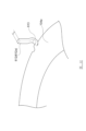
- Fig. 10 is a perspective view that shows a schematic representation of a portion of the configuration of the first friction plate 104 shown in Fig. 9.
- First friction plate 104 and second friction plate 106 The first friction plate 104 and the second friction plate 106 have the same configuration, except that in order to secure an area where the first friction plate 104 is fixed to the holding plate 102 using rivets or the like, the distance between the outer periphery and the inner periphery of the first friction plate 104 is larger than the distance between the outer periphery and the inner periphery of the second friction plate 106. Therefore, the following description will focus on only the first friction plate 104.
- the first friction plate 104 may include at least one set of engagement portions 600.
- the set of engagement portions 600 may include a first engagement portion 610 and a second engagement portion 620.
- the first engagement portion 610 may be disposed on or near the outer periphery of the first friction plate 104
- the second engagement portion 620 may be disposed on or near the inner periphery of the first friction plate 104.
- the first engagement portion 610 and the second engagement portion 620 can both function as, for example, leaf springs.
- the first engagement portion 610 can include a first surface 612 that extends in a direction intersecting (for example, substantially perpendicular) the main surface 104a of the first friction plate 104 and is biased radially inward.
- the second engagement portion 620 can include a second surface 622 that extends in a direction intersecting (for example, substantially perpendicular) the main surface 104a of the first friction plate 104 and is biased radially outward.
- the first engagement portion 610 and the second engagement portion 620 can be formed as, for example, leaf springs.
- the first engagement portion 610 may include a first surface 612 as illustrated in FIG. 10.
- the first surface 612 may be inclined with respect to the circumferential direction as shown in FIG. 10.
- the first surface 612 may be inclined with respect to the circumferential direction such that the distance R1 between one end (the end on the left side of the drawing) 614 and the rotation axis is greater than the distance R2 between the other end (the end on the right side of the drawing) 616 and the rotation axis.
- the width 618 (and thickness) of the first surface 612 may be designed based on the rigidity required for the first surface 612 to perform its function.
- Such a first engagement portion 610 can be formed, for example, by using press molding to make a cut in the plate-shaped first friction plate 104 that conforms to the shape of the first engagement portion 610, and then bending the cut portion.
- the second surface 622 included in the second engagement portion 620 may be provided opposite the first surface 612 included in the first engagement portion 610 (see FIG. 9).
- the second surface 622 may have a symmetrical shape with respect to a circle centered on the rotation axis and passing through a midpoint between the first surface 612 and the second surface 622. Therefore, the second surface 622 may be inclined in the circumferential direction so that the distance between one end (the end opposite one end 614 of the first surface 612) and the rotation axis is smaller than the distance between the other end (the end opposite the other end 616 of the first surface 612) and the rotation axis.
- the second engagement portion 620 may include a configuration similar to that of the first engagement portion 610.
- First friction member 108A and second friction member 108B are symmetrical with respect to the lining plate 202 (see FIG. 1 ), and therefore may include substantially the same configuration. Therefore, the following description will focus on only the first friction member 108A.
- the first friction member 108A which is generally annular as a whole, may include a set of guide portions 700 at positions corresponding to a set of engagement portions 600 provided on the first friction plate 104.
- the set of guide portions 700 may include a first guide portion 710 and a second guide portion 720.
- the first guide portion 710 may include a first inclined surface 712 that extends circumferentially on the outer periphery and slides against the first surface 612.
- the first inclined surface 712 may extend from one end 714 to the other end 716 and may be inclined so as to increase the distance from the axis of rotation along the direction from the one end 714 to the other end 716.
- the second guide portion 720 may include a second inclined surface 722 that extends circumferentially on the inner circumference and slides against the second surface 622.
- the second inclined surface 722 may extend from one end 724 to the other end 726 and may be inclined so as to decrease the distance from the rotation axis in the direction from the one end 724 to the other end 726.
- the first inclined surface 712 extends at an inclination of about 5 to 10 degrees inward along the circumferential direction on the outer periphery of the first friction member 108A.
- the cut-in depth of the first friction member 108A at the terminal position of the first position that is the furthest from the second position is about one-third to one-half of the radial width of this friction member.
- the second inclined surface 722 extends inwardly along the circumferential direction at an incline so as to coincide with a tangent line along the inner circumference of the first friction member 108A.
- the first friction plate 104 when the first friction plate 104 further rotates in the counterclockwise direction on the paper with respect to the first friction member 108A, when the first surface 612 (second surface 622) reaches any region on the first inclined surface 712 (second inclined surface 722) up to the other end 716 (other end 726), the rotational torque with which the first friction plate 104 tries to rotate with respect to the first friction member 108A and the friction coefficient ( ⁇ ) generated between the first surface 612 (second surface 622) and the first inclined surface 712 (second inclined surface 722) are balanced. In this case, the first friction plate 104 cannot rotate relative to the first friction member 108A in either the clockwise or counterclockwise direction. As a result, the first friction plate 104 and the first friction member 108A are fixed to each other and can rotate together thereafter.
- the first engagement portion 610 and the second engagement portion 620, and the first friction plate 104 can be designed so that when the first surface 612 (second surface 622) reaches any region (second region) on the first inclined surface 712 (second inclined surface 722) before reaching the other end 716 (other end 726), the rotational torque with which the first friction plate 104 tries to rotate relative to the first friction member 108A is balanced with the friction coefficient ( ⁇ ) generated between the first surface 612 (second surface 622) and the first inclined surface 712 (second inclined surface 722).
- the first friction plate 104 is in a position (first position) in which it can rotate relative to the first friction member 108A.
- the first friction plate 104 is in a position fixed to the first friction member 108A, that is, the first friction plate 104 is in a position (second position) where it rotates integrally with the first friction member 108A.
- FIG. 11 is a perspective view showing another example of the first engaging portion 610 and the second engaging portion 620 included in the damper device 1 shown in FIG. 9.
- FIG. 12 is a perspective view showing yet another example of the first engaging portion 610 and the second engaging portion 620 included in the damper device 1 shown in FIG. 9.
- the first engagement portion 610 can include a first surface 612a configured to include a width that decreases in a direction away from the main surface 104a of the first friction plate 104.
- the angle ⁇ that each side of the first surface 612a makes with respect to the main surface 104a can be designed based on the rigidity required for the first surface 612a to perform its function.
- the first engagement portion 610 can include a curved portion 613 that is located between the first surface 612 (FIG. 10) or the first surface 612a (FIG. 11) and the main surface 104a and is continuously connected to both.
- the curved portion 613 can include a substantially arc-shaped cross-sectional shape. The radius of this arc can be designed based on the rigidity required for the first surface 612 (FIG. 10) or the first surface 612a (FIG. 11) to perform its function.
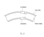
- FIG. 13 is a top view that typically shows another example of the damper device 1 shown in Fig. 9.
- the set of engaging portions 800 may include a first engaging portion 810 and a second engaging portion 820.
- the first engaging portion 810 and the second engaging portion 820 may be formed as a cantilever spring (plate cantilever spring) as illustrated in FIG. 14.
- the first engaging portion 810 formed as a cantilever spring may include a first surface 812. This first surface 812 may perform the same function as the above-described first surface 612 (FIG. 10) or first surface 612a (FIG. 11), etc.
- the cantilever spring 810 illustrated in FIG. 14 causes a twist in the support portion 814 that supports the first surface 812 when the first surface 812 is pressed in a direction radially outward from the first inclined surface 712. This increases the coefficient of friction ( ⁇ ) between the first surface 812 and the first inclined surface 712.
- first friction plate 104 and the second friction plate 106 hold the first friction member 108A and the second friction member, respectively, and the lining plate 202 sandwiched between the first friction member 108A and the second friction member is provided so as to be slidable relative to the first friction member 108A and the second friction member.
- the lining plate 202 holds the first friction member 108A facing it on one side and holds the second friction member 108B facing it on the other side
- the first friction plate 104 is provided so as to be slidable relative to the first friction member 108A
- the second friction plate 106 is provided so as to be slidable relative to the second friction member 108B.
- FIG. 15 is a cross-sectional view that shows a schematic diagram of another example of the damper device 1 shown in FIG. 1.
- the lining plate 202 included in the second rotating body 200 is disposed between the lining plate 202 and the first friction plate 104 included in the first rotating body 100 with the first friction member 108A sandwiched therebetween, and further, the lining plate 202 and the second friction plate 106 included in the first rotating body 100 with the second friction member 108B sandwiched therebetween.
- the first friction plate 104 (second friction plate 106) is not fixed to the first friction member 108A (second friction member 108B) unlike the configuration shown in FIG. 1, but can be provided slidably. Specifically, when the fluctuating torque between the first rotating body 100 (holding plate 102) and the third rotating body (hub) is smaller than a predetermined value (limit torque value), the first friction plate 104 (second friction plate 106) can rotate integrally with the first friction member 108A (second friction member 108B). On the other hand, when the fluctuating torque reaches the predetermined value, the first friction member 108A (second friction member 108B) starts to slip (slide) against the first friction plate 104 (second friction plate 106).
- the lining plate 202 may include a first engagement portion 410, 610, or 810 according to the various embodiments described above on one surface facing the first friction member 108A.
- the lining plate 202 may also include a second engagement portion 420, 620, or 820 according to the various embodiments described above on the other surface facing the second friction member 108B.
- the lining plate 202 can be provided rotatably relative to the first friction member 108A and the second friction member 108B. Thereafter, when the damper device 1 is used for the first time, the lining plate 202 can be fixed to the first friction member 108A and the second friction member 108B. Thereafter, the lining plate 202 can rotate integrally with the first friction member 108A and the second friction member 108B.
- one of the first target member (first friction plate 104, second friction plate 106) included in the first rotating body 100 and the second target member (lining plate 202) included in the second rotating body 200 is rotatably arranged from a first position where it can rotate relatively to the friction member to a second position where it is fixed to the friction member, while the other member is arranged to be slidable relative to the friction member.
- the first friction plate 104 (second friction plate 106) is the target member
- the first friction plate 104 (second friction plate 106) is rotatably arranged from a first position where it is rotatable relative to the first friction member 108A (second friction member 108B) to a second position where it is fixed relative to the first friction member 108A (second friction member 108B), while the lining plate 202 is slidably arranged relative to the first friction member 108A and the second friction member 108B.
- the lining plate 202 When the lining plate 202 is the target member, the lining plate 202 is rotatably mounted from a first position where it is rotatable relative to the first friction member 108A and the second friction member 108B to a second position where it is fixed relative to these friction members, while the first friction plate 104 and the second friction plate 106 are slidably mounted relative to the first friction member 108A and the second friction member 108B, respectively.
- the engagement portion 400 (600, 800) includes “both” of the first engagement portion 410 (610, 810) and the second engagement portion 420 (620, 820), and the guide portion 500 (700) includes “both” of the first guide portion 510 (710) and the second guide portion 520 (720).
- the engagement portion 400 (600, 800) includes “only one” of the first engagement portion 410 (610, 810) and the second engagement portion 420 (620, 820)
- the guide portion 500 (700) includes “only one” of the first guide portion 510 (710) and the second guide portion 520 (720).
- the first engagement portion 410 (610, 810) is used
- the first guide portion 510 (710) is used
- the second engagement portion 420 (620, 820) the second guide portion 520 (720) can be used.
- the first convex portion 416 (second convex portion 426) is described as engaging with the first sliding surface 512 (second sliding surface 522) and the first recess 514 (second recess 524).
- the first surface 612 slides on the first inclined surface 712 (second inclined surface 722).
- the first surface 612 etc. engages with the first sliding surface 512 (second sliding surface 522) and the first recess 514 (second recess 524).
- one of the first target member included in the first rotating body and the second target member included in the second rotating body is rotatably arranged from a first position where it is rotatable relative to the friction member to a second position where it is fixed relative to the friction member, while the other of the first target member and the second target member is slidably arranged relative to the friction member.
- a first convex portion (second convex portion) formed on the one target member abuts against a first sliding surface (second sliding surface) formed on the friction member, and when one target member is in a second position, the first convex portion (second convex portion) can engage with a first recess (second recess) formed on the friction member.
- a first convex portion and a second convex portion can be formed on these plates, and in the process of molding the friction member, a first sliding surface, a second sliding surface, a first recess, and a second recess can be formed on the friction member.
- the first surface (second surface) formed on the one target member abuts against a first region (third region) of the first inclined surface (second inclined surface) formed on the friction member that is closer to the rotation axis
- the first surface (second surface) can abut against a second region (fourth region closer to the rotation axis) of the first inclined surface (second inclined surface) that is farther from the rotation axis than the first region (third region).
- a first surface and a second surface can be formed on these plates, and in the process of molding the friction member, a first inclined surface and a second inclined surface can be formed on the friction member.
- the technology disclosed in this application makes it possible to provide a damper device in which a friction member serving as a limiter material is fixed to a retaining member by an improved method.
- the damper device may include a first rotating body that receives power from a drive source and rotates around a rotating shaft, a second rotating body that engages with the first rotating body via a friction member and receives power from the first rotating body and rotates around the rotating shaft, a third rotating body that rotates around the rotating shaft relatively to the second rotating body, and an elastic mechanism that is arranged between the second rotating body and the third rotating body along a circumferential direction and expands or contracts, a first target member included in the first rotating body and a second target member included in the second rotating body are arranged with the friction member sandwiched between the first target member and the second target member, one of the first target member and the second target member is rotatably provided from a first position rotatable relative to the friction member to a second position fixed relative to the friction member, and the other of the first target member and the second target member is slidably provided on the friction member.
- the damper device can employ the configuration of the first aspect described above, in which "the first rotating body and the friction member are fixed to each other by the first target member rotating to the second position as the one target member, or the second rotating body and the friction member are fixed to each other by the second target member moving to the second position as the one target member.”
- the damper device can adopt the configuration of the first aspect described above, in which "the one target member and the friction member each have a substantially annular shape, the one target member includes a first convex portion on its outer periphery that protrudes radially inward and is biased, the friction member includes a first sliding surface on its outer periphery that slides the first convex portion, and a first recess that is recessed radially inward from the first sliding surface, and when the one target member is in the first position, the first convex portion abuts against the first sliding surface, and when the one target member is in the second position, the first convex portion engages with the first recess.”
- the damper device can adopt a configuration in the first or third aspect described above, in which "the one target member and the friction member each have a substantially annular shape, the one target member includes a second convex portion on its inner circumference that protrudes radially outward and is biased, the friction member includes a second sliding surface on its inner circumference that slides the second convex portion, and a second recess that is recessed radially outward from the second sliding surface, and when the one target member is in the first position, the second convex portion abuts against the second sliding surface, and when the one target member is in the second position, the second convex portion engages with the second recess.”
- the damper device can adopt the configuration of the first aspect described above, in which "the one target member and the friction member each have a substantially annular shape, the one target member includes a first surface at its outer periphery that extends in a direction intersecting with the main surface of the one target member and is biased radially inward, the friction member includes a first inclined surface at its outer periphery that extends at an incline along the circumferential direction and causes the first surface to slide, and when the one target member is in the first position, the first surface abuts against a first region of the first inclined surface that is closer to the rotation axis, and when the one target member is in the second position, the first surface abuts against a second region of the first inclined surface that is farther from the rotation axis than the first region.”
- the damper device may adopt a configuration in the first aspect or the sixth aspect, in which "the one target member and the friction member each have a substantially annular shape, the one target member includes a second surface at its inner circumference that extends in a direction intersecting with the main surface of the one target member and is biased radially outward, the friction member includes a second inclined surface at its inner circumference that extends at an angle along the circumferential direction and slides against the second surface, and when the one target member is in the first position, the second surface abuts against a third region of the second inclined surface that is farther from the rotation axis, and when the one target member is in the second position, the second surface abuts against a fourth region of the second inclined surface that is closer to the rotation axis than the third region.”
- the damper device can employ a configuration in the first or second aspect described above in which "the one target member is restricted from rotating in a direction further away from the second position at the terminal position among the first positions that is the farthest from the second position.”
Landscapes
- Engineering & Computer Science (AREA)
- General Engineering & Computer Science (AREA)
- Mechanical Engineering (AREA)
- Physics & Mathematics (AREA)
- Acoustics & Sound (AREA)
- Aviation & Aerospace Engineering (AREA)
- Mechanical Operated Clutches (AREA)
Abstract
【課題】 リミッタ材としての摩擦部材が向上した手法により保持部材に固定されるダンパ装置を提供すること。 【解決手段】 ダンパ装置は「回転軸の周りに回転する第1回転体(100)と、第1回転体に摩擦部材(108)を介して係合して第1回転体から動力を伝達されて、回転軸の周りに回転する第2回転体(200)と、回転軸の周りに第2回転体に対して相対的に回転する第3回転体と、周方向に沿って第2回転体と第3回転体との間に配置され、伸長又は縮小する弾性機構部(206)と、を含み、第1回転体に含まれる第1対象部材(104,106)及び第2回転体に含まれる第2対象部材(202)が、第1対象部材と第2対象部材との間に摩擦部材を挟んで配置され、第1対象部材及び第2対象部材のうちの一方の対象部材が、摩擦部材に対して相対的に回転可能な第1位置から、摩擦部材に固定される第2位置に、回転可能に設けられる」構成を含む。
Description
本件出願に開示された技術は、駆動源と変速機との間に配置され、駆動源と変速機との間に生じるトルク変動を吸収するダンパ装置に関する。
従来技術に係るダンパ装置として、特許文献1(特許第4581576号公報)に開示されたものが知られている。特許文献1に開示されたダンパ装置は、駆動源からの動力が伝達され中心軸の周りに回転する保持プレートと、この保持プレートに対して摩擦部材等を介して係合することにより中心軸の周りに回転するダンパ機構と、このダンパ機構との間にコイルスプリングを挟んで設けられ中心軸の周りに回転するハブと、を含む。
このようなダンパ装置にあっては、保持プレートとハブとの間の変動トルクが所定値(リミットトルク値)より小さいときには、回転トルクが、保持プレートから摩擦部材等を介してダンパ機構のディスクに伝達される。これにより、駆動力がダンパ機構及びハブを介して変速機の入力軸に伝達される。一方、上記変動トルクが所定値(リミットトルク値)に達すると、摩擦部材が滑り始める(摺動し始める)ことにより、ダンパ機構及びハブには、所定値(リミットトルク値)以上の変動トルクが伝達されなくなる。
ここで、リミッタ材として機能する摩擦部材は、ダンパ機構に含まれるディスク(すなわち、摩擦部材を保持する保持部材)の両面に接着剤を用いて接着される。特許文献1には記載されていないが、このような摩擦部材は、カシメ又はリベットを用いて保持部材に固定され得ることも知られている。なお、特許文献1の全体の内容が引用により本明細書に組み入れられる。
しかしながら、上述した従来技術に係るダンパ装置にあっては、リミッタ材としての摩擦部材を保持部材に固定する際には、そのような固定を行うための専用工程、及び、接着剤又はリベット等の専用部品が必要である。この結果、ダンパ装置を製造するためのコストが高くなるという問題がある。
そこで、本件出願に開示された技術は、リミッタ材としての摩擦部材が向上した手法により保持部材に固定されるダンパ装置を提供する。
一態様に係るダンパ装置は、「駆動源からの動力が伝達され回転軸の周りに回転する第1回転体と、該第1回転体に対して摩擦部材を介して係合して該第1回転体から動力を伝達されることにより、前記回転軸の周りに回転する第2回転体と、前記回転軸の周りに該第2回転体に対して相対的に回転する第3回転体と、周方向に沿って前記第2回転体と前記第3回転体との間に配置され、伸長又は縮小する弾性機構部と、を具備し、前記第1回転体に含まれる第1対象部材及び前記第2回転体に含まれる第2対象部材が、該第1対象部材と該第2対象部材との間に前記摩擦部材を挟んで配置され、該第1対象部材及び該第2対象部材のうちの一方の対象部材が、前記摩擦部材に対して相対的に回転可能な第1位置から、該摩擦部材に対して固定される第2位置に、回転可能に設けられ、前記第1対象部材及び前記第2対象部材のうちの他方の対象部材が、前記摩擦部材に対して摺動可能に設けられる」構成を採用することができる。
本件出願に開示された技術によれば、リミッタ材としての摩擦部材が向上した手法により保持部材に固定されるダンパ装置を提供することができる。
以下、添付図面を参照して様々な実施形態を説明する。なお、図面において共通した構成要素には同一の参照符号が付されている。また、或る図面に表現された構成要素が、説明の便宜上、別の図面においては省略されていることがある点に留意されたい。さらにまた、添付した図面が必ずしも正確な縮尺で記載されている訳ではないということに注意されたい。
1.ダンパ装置の全体的な構成
図1は、一実施形態に係るダンパ装置における一部の構成を模式的に示す断面図である。このようなダンパ装置1は、図示しない駆動源(例えばエンジン又はモーター)と図示しない変速機との間に配置され得る。
図1は、一実施形態に係るダンパ装置における一部の構成を模式的に示す断面図である。このようなダンパ装置1は、図示しない駆動源(例えばエンジン又はモーター)と図示しない変速機との間に配置され得る。
図1に示すように、ダンパ装置1は、大まかにいえば、駆動源からの駆動力が伝達され回転軸の周りに回転する第1回転体100と、第1回転体100から摩擦部材108を介して動力を伝達されることにより、回転軸の周りに回転する第2回転体200と、を含むことができる。
さらに、説明を簡略化するために、図1には示されていないが、ダンパ装置1は、回転軸の周りに第2回転体200に対して相対的に回転する第3回転体(ハブ)を、さらに含むことができる。この図示しない第3回転体は、図1において第2回転体200の紙面上下方に配置され得る。この第3回転体の回転軸(中心軸)が、第1回転体100及び第2回転体の各々の回転軸(中心軸)と一致し得る。
(1)第1回転体100
第1回転体100は、保持プレート102と、第1摩擦プレート(第1プレッシャープレート)104と、第2摩擦プレート(第2プレッシャープレート)106と、摩擦部材108と、皿バネ110と、を含むことができる。
第1回転体100は、保持プレート102と、第1摩擦プレート(第1プレッシャープレート)104と、第2摩擦プレート(第2プレッシャープレート)106と、摩擦部材108と、皿バネ110と、を含むことができる。
図示しない駆動源からの動力が伝達される保持プレート102は、全体として略環状の形状を呈することができる。保持プレート102は、外周部分において第1摩擦プレート104に当接して図示しないリベット等により固定され、外周部分から径方向内側に隣接する部分において、この保持プレート102と第1摩擦プレート104との間に距離を隔てて収容空間を確保するように、構成され得る。この収容空間には、第2摩擦プレート106、摩擦部材108及び皿バネ110等が収容され得る。
第1摩擦プレート104は、全体として略環状の形状を呈することができ、熱間圧延鋼板(SPH)又はステンレス鋼板(SUS)等の材料により形成され得る。第1摩擦プレート104は、上述したとおり、保持プレート102に図示しないリベット等により固定され得る。第1摩擦プレート104は、摩擦部材108のうち第1摩擦部材108Aに当接してこの第1摩擦部材108Aを保持することができる。第1摩擦プレート104の具体的な構成については、後述する。
第2摩擦プレート106は、全体として略環状の形状を呈することができ、熱間圧延鋼板(SPH)又はステンレス鋼板(SUS)等の材料により形成され得る。第2摩擦プレート106は、この第2摩擦プレート106と第1摩擦プレート104との間に、摩擦部材108(具体的には第1摩擦部材108A及び第2摩擦部材108B)等を挟むように、第1摩擦プレート104に対向して設けられ得る。第2摩擦プレート106は、摩擦部材108のうち第2摩擦部材108Bに当接してこの第2摩擦部材108Bを保持することができる。第2摩擦プレート106の具体的な構成については、後述する。
摩擦部材108は、各々が略環状の形状を呈する2つの摩擦部材108A及び108Bを含むことができる。各摩擦部材108A及び108Bは、一般的に知られる材料(例えば、コルクモールド、ゴムモールド、ペーパーベース、ガラスヤーン、セミメタリック等)により形成され得る。上述したように、摩擦部材108A及び108Bは、それぞれ、第1摩擦プレート104及び第2摩擦プレート106により保持され得る。これら摩擦部材108A及び108Bの間には、第2回転体200の後述するライニングプレート202が配置され得る。
皿バネ110は、全体として略環状の形状を呈することができ、例えばステンレス鋼(SUS)等の材料により形成され得る。皿バネ110は、その外周縁付近において保持プレート102に当接し、その内周縁付近において第2摩擦プレート106に当接するように、配置される。皿バネ110は、第2摩擦プレート106を第1摩擦プレート104に向かう方向に付勢することができる。
(2)第2回転体200
第2回転体200は、ライニングプレート202と、サイドプレート204と、弾性機構部206と、を含むことができる。
第2回転体200は、ライニングプレート202と、サイドプレート204と、弾性機構部206と、を含むことができる。
ライニングプレート202は、全体として略環状を呈することができ、例えば、熱間圧延鋼板(SPH)又はステンレス鋼板(SUS)等の材料により形成され得る。ライニングプレート202は、外周縁付近において、上述した第1回転体100の第1摩擦部材108Aと第2摩擦部材108Bとの間に挟まれ得る。これにより、ライニングプレート200を含む第2回転体200は、摩擦部材108を介して第1回転体100に係合して第1回転体100から動力を伝達されることにより、回転軸の周りに回転することができる。
さらに、ライニングプレート202は、内周縁付近において、リベット等によりサイドプレート204に固定され得る。
サイドプレート204は、2つのサイドプレート、すなわち、第1サイドプレート204A及び第2サイドプレート204Bを含むことができる。各サイドプレート204A、204Bは、全体として略環状を呈することができる。
各サイドプレート204A、204Bは、外周部分において、間にライニングプレート202を挟んで、リベット等により相互に固定され得る。また、各サイドプレート204A、204Bは、外周部分から径方向内側に隣接する部分において、相互に距離を隔てて収容領域を形成することができる。この収容領域には、弾性機構部206等が収容され得る。
弾性機構部206は、弾性体(コイルスプリング)206Aと、弾性体206の両端に配置され弾性体206を支持する図示しないシート等と、を含む少なくとも1組の機構を含むことができる。このような弾性機構部206は、図示はされていないが、周方向に沿って、第2回転体200(に含まれるサイドプレート204)と第3回転体(ハブ)との間に配置され得る。
(3)第3回転体
図示しない第3回転体(ハブ)は、全体として略環状を呈し得る。第3回転体は、その中心部分から径方向外側に向かって延びる(図示しない)少なくとも1つのフランジ部分を含むことができる。第3回転体は、このフランジ部分と第2回転体200のサイドプレート204との間に周方向に沿って配置された弾性機構部206を介して、第2回転体200から動力を伝達される。第3回転体は、弾性機構部206を伸長又は縮小させて、回転軸の周りに第2回転体に対して相対的に回転することができる。
図示しない第3回転体(ハブ)は、全体として略環状を呈し得る。第3回転体は、その中心部分から径方向外側に向かって延びる(図示しない)少なくとも1つのフランジ部分を含むことができる。第3回転体は、このフランジ部分と第2回転体200のサイドプレート204との間に周方向に沿って配置された弾性機構部206を介して、第2回転体200から動力を伝達される。第3回転体は、弾性機構部206を伸長又は縮小させて、回転軸の周りに第2回転体に対して相対的に回転することができる。
第3回転体は、その中心部分に挿通させた(図示しない)変速機の入力軸に固定されることにより、変速機に動力を伝達することができる。
2.ダンパ装置1の一般的な動作
上記構成を含むダンパ装置1の一般的な動作は以下のとおりである。
図示しない駆動源からの動力が保持プレート102に伝達されることにより、保持プレート102を含む第1回転体100は、回転軸の周りに回転することができる。
上記構成を含むダンパ装置1の一般的な動作は以下のとおりである。
図示しない駆動源からの動力が保持プレート102に伝達されることにより、保持プレート102を含む第1回転体100は、回転軸の周りに回転することができる。
第1回転体100(保持プレート102)と第3回転体(ハブ)との間の変動トルクが所定値(リミットトルク値)より小さいときには、回転トルクが、第1回転体100から摩擦部材108を介してライニングプレート202に伝達されることにより、第2回転体200が回転することができる。
ライニングプレート202に伝達された回転トルクは、サイドプレート204、弾性機構部206を介して、第3回転体(ハブ)に伝達される。これにより、変動トルクに応じて弾性機構部206が伸張又は縮小しながら、第3回転体(ハブ)は回転することができる。このように第3回転体(ハブ)が回転することにより、動力が図示しない変速機に伝達される。
上記の状態から駆動源の駆動トルクが増加して、第1回転体100(保持プレート102)と第3回転体(ハブ)との間の変動トルクが所定値(リミットトルク値)に達したときには、摩擦部材108がライニングプレート202に対して滑り始める。これにより、第1回転体100から第2回転体200には、所定値(リミットトルク値)以上の変動トルクは伝達されなくなる。
3.ダンパ装置1の具体的な構成
ダンパ装置1が工場出荷時(未使用時)の状態では、第1摩擦部材108Aは、第1摩擦プレート104に対して回転可能に設けられ得る。この後、ダンパ装置1が初めて使用された状態において、第1摩擦部材108Aは、第1摩擦プレート104に対して固定され得る。これにより、以後、第1摩擦部材108Aは、第1摩擦プレート104と一体的に回転することができる。
ダンパ装置1が工場出荷時(未使用時)の状態では、第1摩擦部材108Aは、第1摩擦プレート104に対して回転可能に設けられ得る。この後、ダンパ装置1が初めて使用された状態において、第1摩擦部材108Aは、第1摩擦プレート104に対して固定され得る。これにより、以後、第1摩擦部材108Aは、第1摩擦プレート104と一体的に回転することができる。
同様に、ダンパ装置1が工場出荷時(未使用時)の状態では、第2摩擦部材108Bは、第2摩擦プレート106に対して回転可能に設けられ得る。この後、ダンパ装置1が初めて使用された状態において、第2摩擦部材108Bは、第2摩擦プレート106に対して固定され得る。これにより、以後、第2摩擦部材108Bは、第2摩擦プレート106と一体的に回転することができる。
以下、このような機能を実現するためにダンパ装置1に施された具体的な構成について、図1に加えて、図2~図6を参照して説明する。
図2は、図1に示したダンパ装置1に含まれる第1摩擦プレート104(第2摩擦プレート106)の一部の構成を模式的に示す斜視図である。図3は、図2に示した第1摩擦プレート104(第2摩擦プレート106)の構成をA-A切断面からみて模式的に示す断面図である。図4(a)及び図4(b)は、図2に示した第1摩擦プレート104(第2摩擦プレート106)の構成を模式的に示す上面図であり、図4(c)は、図2に示した第1摩擦プレート104(第2摩擦プレート106)の一部の構成を模式的に示す斜視図である。図5は、図2に示した第1摩擦プレート104(第2摩擦プレート106)の一部の構成を模式的に示す上面図である。図6は、図1に示したダンパ装置1に含まれる摩擦部材108の一部の構成を模式的に示す上面図である。
なお、第1摩擦プレート104と第2摩擦プレート106とは、第1摩擦プレート104が保持プレート102に当接して延びる外周部分を含むという点を除き、略同様の構成を含み得る。したがって、ここでは、便宜上、第1摩擦プレート104及びこれに対応付けて設けられる第1摩擦部材108Aのみに着目して説明するが、このような第1摩擦プレート104及びこれに対応付けて設けられる第1摩擦部材108Aの構成は、第2摩擦プレート106及びこれに対応付けて設けられる第2摩擦部材108Bの構成にも同様に当て嵌まるものである。
3-1.第1摩擦プレート104
図2を参照すると、第1摩擦プレート104は、少なくとも1組の係合部400を含むことができる。1組の係合部400は、第1係合部410及び第2係合部420を含むことができる。
図2を参照すると、第1摩擦プレート104は、少なくとも1組の係合部400を含むことができる。1組の係合部400は、第1係合部410及び第2係合部420を含むことができる。
(1)第1係合部410
第1係合部410は、第1摩擦プレート104の主面104aからこの主面104aに交差する方向に(例えば略垂直に)延びる支持部412と、支持部412に連続的に繋がり径方向内側に向かって突出する第1凸部416と、を含むことができる。なお、図2には、示されていないが、第1係合部410の径方向外側には、第1摩擦プレートの主面104aがさらに延在し得る(このように延在した主面104aが、図1に示すように、リベット等により保持プレート102に固定され得る)。
第1係合部410は、第1摩擦プレート104の主面104aからこの主面104aに交差する方向に(例えば略垂直に)延びる支持部412と、支持部412に連続的に繋がり径方向内側に向かって突出する第1凸部416と、を含むことができる。なお、図2には、示されていないが、第1係合部410の径方向外側には、第1摩擦プレートの主面104aがさらに延在し得る(このように延在した主面104aが、図1に示すように、リベット等により保持プレート102に固定され得る)。
上述したように、第1摩擦プレート104は、熱間圧延鋼板(SPH)又はステンレス鋼板(SUS)等の材料により形成され得ることから、第1摩擦プレート104の一部である、支持部412及び第1凸部416もまた、同様の材料により形成され得る。
支持部412は、主面104aから第1摩擦部材108Aが配置される方向に延びる。支持部412は、略U字状の断面形状を呈する湾曲部414を含むこともできる。支持部412は、第1凸部416から径方向外側に向かって押圧されたときに、第1凸部416を径方向内側に向かって付勢することができる。
第1凸部416は、支持部412によって、径方向内側に向かって付勢され得る。第1凸部416は、その端部において例えば半円形状を呈することができる。
なお、第1係合部410の支持部412は、図1に例示されるように、湾曲部414を欠いた構成を採用することも可能である。
このような第1係合部410は、例えばプレス成形を利用して、板状の第1摩擦プレート104に第1係合部410の形状に沿った切込みを施し、このように切込みを施した部分を折り曲げること等により、形成可能である。
なお、このような第1係合部410は、図1に例示されるように、第1摩擦プレート104の内周と外周との間における領域に形成され得る。
(2)第2係合部420
図2に示すように、第2係合部420は、上述した第1係合部410と同様の構成を含むことができる。具体的には、第1摩擦プレート104の内周又は内周付近に形成され得る第2係合部420は、第1摩擦プレート104の主面104aからこの主面104aに交差する方向に(例えば略垂直に)延びる支持部422と、支持部422に連続的に繋がり径方向外側に向かって突出する第2凸部426と、を含むことができる。
図2に示すように、第2係合部420は、上述した第1係合部410と同様の構成を含むことができる。具体的には、第1摩擦プレート104の内周又は内周付近に形成され得る第2係合部420は、第1摩擦プレート104の主面104aからこの主面104aに交差する方向に(例えば略垂直に)延びる支持部422と、支持部422に連続的に繋がり径方向外側に向かって突出する第2凸部426と、を含むことができる。
上述したように、第1摩擦プレート104は、熱間圧延鋼板(SPH)又はステンレス鋼板(SUS)等の材料により形成され得ることから、第1摩擦プレート104の一部である、支持部422第2凸部426もまた、同様の材料により形成され得る。
支持部422は、主面104aから第1摩擦部材108Aが配置される方向に延びる。支持部422は、略U字状の断面形状を呈する湾曲部424を含むこともできる。支持部422は、第2凸部426から径方向内側に向かって押圧されたときに、第2凸部426を径方向外側に向かって付勢することができる。
第2凸部426は、支持部422によって、径方向外側に向かって付勢され得る。第2凸部426は、その端部において例えば半円形状を呈することができる。
なお、第2係合部420の支持部422は、図1に例示されるように、湾曲部424を欠いた構成を採用することも可能である。
このような第2係合部420は、例えばプレス成形を利用して、板状の第1摩擦プレート104に第2係合部420の形状に沿った切込みを施し、このように切込みを施した部分を折り曲げること等により、形成可能である。
(3)係合部400の断面形状
図3(a)は、図2に示した第1摩擦プレート104(第2摩擦プレート106)のA-A切断面からみた構成を示す断面図である。図3(a)に示すように、支持部412(422)は、第1摩擦プレート104の主面104aに対して略直角に延びることができる。支持部412(422)は、略U字状の断面形状を呈する湾曲部414(424)を含むことができる。第1凸部416(第2凸部426)は、主面104aに対して略平行に延びることができる。
図3(a)は、図2に示した第1摩擦プレート104(第2摩擦プレート106)のA-A切断面からみた構成を示す断面図である。図3(a)に示すように、支持部412(422)は、第1摩擦プレート104の主面104aに対して略直角に延びることができる。支持部412(422)は、略U字状の断面形状を呈する湾曲部414(424)を含むことができる。第1凸部416(第2凸部426)は、主面104aに対して略平行に延びることができる。
図3(a)に示した構成は、第1摩擦プレート104等に設けられる係合部400の単なる一例に過ぎない。係合部400は、例えば図3(b)~図3(g)に示した構成を採用することも可能である。
図3(b)に示すように、第1係合部410aは、主面104aに交差する方向に(例えば略垂直に)延びる支持部412aと、支持部412aに連続的に繋がり径方向内側(紙面上左側)に向かって突出する第1凸部416aと、を含むことができる。第1凸部416aは、支持部412aにより径方向内側(紙面上左側)に向かって付勢され得る。
同様に、第2係合部420aは、主面104aに交差する方向に(例えば略垂直に)延びる支持部422aと、支持部422aに連続的に繋がり径方向外側(紙面上右側)に向かって突出する第2凸部426aと、を含むことができる。第2凸部426aは、支持部422aにより径方向外側(紙面上右側)に向かって付勢され得る。
図3(c)に示すように、第1係合部410bは、2つの円弧とその間に延びる1つの直線とを組み合わせた断面形状を呈する支持部412bと、支持部412bに連続的に繋がり径方向内側(紙面上左側)に向かって突出する第1凸部416bと、を含むことができる。第1凸部416bは、支持部412bにより径方向内側(紙面上左側)に向かって付勢され得る。
同様に、第2係合部420bは、2つの円弧とその間に延びる1つの直線とを組み合わせた断面形状を呈する支持部422bと、支持部422bに連続的に繋がり径方向外側(紙面上右側)に向かって突出する第2凸部426bと、を含むことができる。第2凸部426bは、支持部422bにより径方向外側(紙面上右側)に向かって付勢され得る。
図3(d)に示すように、第1係合部410cは、全体として円弧状の断面形状を呈する支持部412cと、支持部412cに連続的に繋がり径方向内側(紙面上左側)に向かって突出する第1凸部416cと、を含むことができる。第1凸部416cは、支持部412cにより径方向内側(紙面上左側)に向かって付勢され得る。
同様に、第2係合部420cは、全体として円弧状の断面形状を呈する支持部422cと、支持部422cに連続的に繋がり径方向外側(紙面上右側)に向かって突出する第2凸部426cと、を含むことができる。第2凸部426cは、支持部422cにより径方向外側(紙面上右側)に向かって付勢され得る。
図3(e)に示すように、第1係合部410dは、全体として三角形状の断面形状を呈する支持部412dと、支持部412dに連続的に繋がり径方向内側(紙面上左側)に向かって突出する第1凸部416dと、を含むことができる。第1凸部416dは、支持部412dにより径方向内側(紙面上左側)に向かって付勢され得る。
同様に、図3(e)では、図示が省略されているが、第2係合部420dは、全体として三角形状の断面形状を呈する支持部422dと、支持部422dに連続的に繋がり径方向外側(紙面上右側)に向かって突出する第2凸部426dと、を含むことができる。第2凸部426dは、支持部422dにより径方向外側(紙面上右側)に向かって付勢され得る。
図3(f)に示すように、第1係合部410eは、2つの直線とその間に延びる円弧とを組み合わせた断面形状を呈する支持部412eと、支持部412eに連続的に繋がり径方向内側(紙面上左側)に向かって突出する第1凸部416eと、を含むことができる。第1凸部416eは、支持部412eにより径方向内側(紙面上左側)に向かって付勢され得る。
同様に、図3(f)では、図示が省略されているが、第2係合部420eは、2つの直線とその間に延びる円弧とを組み合わせた断面形状を呈する支持部422eと、支持部422eに連続的に繋がり径方向外側(紙面上右側)に向かって突出する第2凸部426eと、を含むことができる。第2凸部426eは、支持部422eにより径方向外側(紙面上右側)に向かって付勢され得る。
図3(g)に示すように、第1係合部410fは、全体として略円状の断面形状を呈する支持部412fと、支持部412fに連続的に繋がり径方向内側(紙面上左側)に向かって突出する第1凸部416fと、を含むことができる。第1凸部416fは、支持部412fにより径方向内側(紙面上左側)に向かって付勢され得る。
同様に、図3(g)では、図示が省略されているが、第2係合部420fは、全体として略円状の断面形状を呈する支持部422fと、支持部422fに連続的に繋がり径方向外側(紙面上右側)に向かって突出する第2凸部426fと、を含むことができる。第2凸部426fは、支持部422fにより径方向外側(紙面上右側)に向かって付勢され得る。
(4)係合部400のその他の構成
図4(a)は、図2に示した第1摩擦プレート104(第2摩擦プレート106)の構成を示す上面図である。図4(a)に示した構成は、第1摩擦プレート104等に設けられる係合部400の単なる一例に過ぎない。図4(b)に示すように、第1摩擦プレート104(第2摩擦プレート106)において、各係合部400の周方向両側には、この係合部400に隣接する逃し(切欠き)430が形成され得る。
図4(a)は、図2に示した第1摩擦プレート104(第2摩擦プレート106)の構成を示す上面図である。図4(a)に示した構成は、第1摩擦プレート104等に設けられる係合部400の単なる一例に過ぎない。図4(b)に示すように、第1摩擦プレート104(第2摩擦プレート106)において、各係合部400の周方向両側には、この係合部400に隣接する逃し(切欠き)430が形成され得る。
図4(c)は、図3(b)に示した第1係合部410a(第2係合部420a)の構成を示す斜視図である。第1係合部410a(第2係合部420a)は、図4(c)に示す手法により形成され得る。具体的には、まず、長手方向に延びる1枚の細長い板の中間部分が、この長手方向に対して略45度の角度を成して延びる第1折り曲げ線432に沿って、折り曲げられる。次に、第1折り曲げ線432から先端434まで延びる部分が、第1折り曲げ線432に対して略45度の角度を成して延びる第2折り曲げ線436に沿って、再度折り曲げられる。これにより、支持部412a(422a)と、支持部412a(422a)に連続的に繋がった第1凸部416a(第2凸部426a)と、を含む第1係合部410a(第2係合部420a)が、形成され得る。
(5)係合部400の第1凸部416及び第2凸部426
図5(a)~図5(e)は、図2に示した第1凸部416及び第2凸部426が採用し得る形状の具体例を示す上面図である。
図5(a)~図5(e)は、図2に示した第1凸部416及び第2凸部426が採用し得る形状の具体例を示す上面図である。
図5(a)に示すように、第1凸部416及び第2凸部426は、円弧状の形状を呈することができる。図5(b)に示すように、第1凸部416及び第2凸部426は、平らな形状を呈することができる。この場合、各凸部の周方向両端には面取りが施され得る。
図5(c)に示すように、第1凸部416及び第2凸部426は、略三角形状の形状を呈することができる。この場合、各凸部の少なくとも1つの角部には面取りが施され得る。
図5(c)に示すように、第1凸部416及び第2凸部426は、略三角形状の形状を呈することができる。この場合、各凸部の少なくとも1つの角部には面取りが施され得る。
図5(d)に示すように、第1凸部416及び第2凸部426は、中央に設けられた凹部440と、凹部440の周方向両端に設けられた2つの凸部442、444と、を含む形状を呈することができる。
図5(e)は、図3(b)及び図4(c)に示した第1係合部410a(第2係合部420a)を示す上面図である。
上述した第1摩擦プレート104は、各組の係合部400が上記のように構成される、複数組の係合部400を含むことができる。例えば、第1摩擦プレート104は、3組の係合部400を含むことができる。この場合、或る1組の係合部400と回転軸とを結ぶ線と、隣接する別の1組の係合部と回転軸とを結ぶ線とが、略120度の角度を成すように、3組の係合部400が設けられ得る。
3-2.第1摩擦部材108A
第1摩擦プレート104に対向して設けられる第1摩擦部材108Aは、例えば図6(a)に示す構成を採用することができる。
第1摩擦プレート104に対向して設けられる第1摩擦部材108Aは、例えば図6(a)に示す構成を採用することができる。
全体として略環状を呈する第1摩擦部材108Aは、第1摩擦プレート104に設けられた1組の係合部400に対応する位置において、1組の案内部500を含むことができる。1組の案内部500は、第1案内部510及び第2案内部520を含むことができる。
第1案内部510は、第1摩擦プレート104に設けられた1組の係合部400のうちの第1係合部410に対応付けて設けられ得る。第2案内部520は、第1摩擦プレート104に設けられた1組の係合部400のうちの第2係合部420に対応付けて設けられ得る。
第1案内部510は、第1摩擦部材108Aの外周において、第1凸部416(図2等参照)を摺動させる第1摺動面512と、第1摺動面512に隣接して設けられ第1摺動面512から径方向内側(紙面上下側)に向かって凹んだ第1凹部514と、を含むことができる。さらに、第1案内部510は、第1摺動面512に隣接して設けられ、第1摺動面512を摺動する第1凸部416に当接して、第1凸部416の摺動を規制する第1壁面519を含むことができる。
第1摺動面512は、その一端516において、第1摩擦部材108Aの外周を基準として深さrだけ径方向内側(回転軸の方向)に位置することができる。第1摺動面512は、その他端518において、第1摩擦部材108Aの外周を基準として深さrより小さい深さだけ径方向内側(回転軸の方向)に位置することができる。これにより、第1摺動面512は、一端516から他端518に向かって、回転軸からの距離を増加させるように傾斜することができる。第1摺動面512は、この面において第1凸部416を摺動させることにより、第1摩擦プレート104と第1摩擦部材108Aとが相対的に回転することを許容する要素であるといえる(これを第2摩擦部材108Bに当て嵌めると、第1摺動面512は、この面において第1凸部416を摺動させることにより、第2摩擦プレート106と第2摩擦部材108Bとが相対的に回転することを許容する要素であるといえる。)
第1凹部514は、一旦この第1凹部514に係合した(嵌合した)第1凸部416を保持することにより、第1摩擦プレート104と第1摩擦部材108Aとが相対的に回転することを規制する、すなわち、第1摩擦プレート104と第1摩擦部材108Aとを固定する要素であるといえる(これを第2摩擦部材108Bに当て嵌めると、第1凹部514は、一旦この第1凹部514に係合した(嵌合した)第1凸部416を保持することにより、第2摩擦プレート106と第2摩擦部材108Bとが相対的に回転することを規制する、すなわち、第2摩擦プレート106と第2摩擦部材108Bとを固定する要素であるといえる)。第1凹部514の形状及び深さ等は、このような機能を果たすことができるように、設計され得る。
第1壁面519は、第1摺動面512に対して交差する方向(例えば略垂直)に延びることができる。第1壁面519は、第1摺動面512を摺動する第1凸部416に当接することにより、第1凸部416が紙面上右側にさらに摺動することを規制し、したがって、第1摩擦プレート104が第1摩擦部材108Aに対して紙面上時計回りの方向にさらに回転することを規制する要素であるといえる(これを第2摩擦部材108Bに当て嵌めると、第1壁面519は、第1摺動面512を摺動する第1凸部416に当接することにより、第1凸部416が紙面上右側にさらに摺動することを規制し、したがって、第2摩擦プレート106が第2摩擦部材108Bに対して紙面上時計回りの方向にさらに回転することを規制する要素であるといえる)。
第2案内部520は、第1摩擦部材108Aの内周において、第2凸部426(図2等参照)を摺動させる第2摺動面522と、第2摺動面522に隣接して設けられ第2摺動面522から径方向外側(紙面上上側)に向かって凹んだ第2凹部524と、を含むことができる。さらに、第2案内部520は、第2摺動面522に隣接して設けられ、第2摺動面522を摺動する第2凸部426に当接して、第2凸部426の摺動を規制する第2壁面529を含むことができる。
第2摺動面522は、その一端526において、第1摩擦部材108Aの外周を基準として深さrだけ径方向外側(回転軸とは反対の方向)に位置することができる。第2摺動面522は、その他端528において、第1摩擦部材108Aの外周を基準として深さrより小さい深さだけ径方向外側(回転軸とは反対の方向)に位置することができる。これにより、第2摺動面522は、一端526から他端528に向かって、回転軸からの距離を減少させるように傾斜することができる。第2摺動面522は、この面において第2凸部426を摺動させることにより、第1摩擦プレート104と第1摩擦部材108Aとが相対的に回転することを許容する要素であるといえる。
第2凹部524は、一旦この第2凹部524に係合した(嵌合した)第2凸部426を保持することにより、第1摩擦プレート104と第1摩擦部材108Aとが相対的に回転することを規制する、すなわち、第1摩擦プレート104と第1摩擦部材108Aとを固定する要素であるといえる。第2凹部524の形状及び深さ等は、このような機能を果たすことができるように、設計され得る。
第2壁部529は、第2摺動面522に対して交差する方向(例えば略垂直)に延びることができる。第2壁部529は、第2摺動面522を摺動する第2凸部426に当接することにより、第2凸部426が紙面上右側にさらに摺動することを規制し、したがって、第1摩擦プレート104が第1摩擦部材108Aに対して紙面上時計回りの方向にさらに回転することを規制する要素であるといえる。
図6(b)は、図6(a)に示した第1摩擦部材108Aの別の例を示す。図6(b)において図6(a)とは異なる点のみに着目して説明する。
第1案内部510aに含まれる第1傾斜面512aは、回転軸からの距離を一定に維持して延びる曲面512a1と、曲面512a1から第1凹部514に向かう方向に沿って回転軸からの距離を増加させるように傾斜する傾斜面512a2と、を含むことができる。
第2案内部520aに含まれる第2傾斜面522aは、回転軸からの距離を一定に維持して延びる曲面522a1と、曲面522a1から第2凹部524に向かう方向に沿って回転軸からの距離を減少させるように傾斜する傾斜面522a2と、を含むことができる。
図6(c)は、図6(a)に示した第1摩擦部材108Aのさらに別の例を示す。図6(c)において図6(a)とは異なる点のみに着目して説明する。
第1案内部510bは、第1傾斜面512に隣接して設けられた第1壁面519bを含むことができる。第1壁面519bは、第1傾斜面512から離れる方向に向かって、回転軸からの距離を増加させるように傾斜することができる。第1壁面519bは、この第1壁面519bを摺動する第1凸部416を径方向外側に向かって押圧することにより、第1凸部416が紙面上右側にさらに摺動することを規制し、したがって、第1摩擦プレート104が第1摩擦部材108Aに対して紙面上時計回りの方向にさらに回転することを規制する要素であるといえる。
第2案内部520bは、第2傾斜面522に隣接して設けられた第2壁面529bを含むことができる。第2壁面529bは、第2傾斜面522から離れる方向に向かって、回転軸からの距離を減少させるように傾斜することができる。第2壁面529bは、この第2壁面529bを摺動する第2凸部426を径方向内側に向かって押圧することにより、第2凸部426が紙面上右側にさらに摺動することを規制し、したがって、第1摩擦プレート104が第1摩擦部材108Aに対して紙面上時計回りの方向にさらに回転することを規制する要素であるといえる。
3-3.第2摩擦プレート106及び第2摩擦部材108B
第2摩擦プレート106及び第2摩擦部材108Bは、それぞれ、上述した第1摩擦プレート104及び第1摩擦部材108Aと略同様の構成を含み得る。具体的には、図1から明らかであるように、第2摩擦プレート106及び第2摩擦部材108Bは、ライニングプレート202を中心として、上述した第1摩擦プレート104及び第1摩擦部材108Aと対称の関係にあることから、上述した第1摩擦プレート104及び第1摩擦部材108Aとは対称の構成を含み得る。
第2摩擦プレート106及び第2摩擦部材108Bは、それぞれ、上述した第1摩擦プレート104及び第1摩擦部材108Aと略同様の構成を含み得る。具体的には、図1から明らかであるように、第2摩擦プレート106及び第2摩擦部材108Bは、ライニングプレート202を中心として、上述した第1摩擦プレート104及び第1摩擦部材108Aと対称の関係にあることから、上述した第1摩擦プレート104及び第1摩擦部材108Aとは対称の構成を含み得る。
但し、図1に示すように、第1摩擦プレート104では、第1係合部410の径方向外側においても第1摩擦プレートの主面104aがさらに延在し得る一方、第2摩擦プレート106では、第1係合部の径方向外側には、第2摩擦プレート106の主面は延在しない。
4.第1摩擦プレート104(第2摩擦プレート106)と第1摩擦部材108A(第2摩擦部材108B)との間で行われる動作
図7は、図1に示したダンパ装置に含まれる第1摩擦プレート104(第2摩擦プレート106)と第1摩擦部材108A(第2摩擦部材108B)との間において行わる動作を模式的に示す図である。図8は、図7(c)に示したE-E切断面からみた第1摩擦プレート104及び第1摩擦部材108Aの構成を模式的に示す断面図である。
上述したように、第1摩擦プレート104と第1摩擦部材108Aとの間の関係は、第2摩擦プレート106と第2摩擦部材108Bとの間の関係にも同様に当て嵌まる。よって、ここでは、第1摩擦プレート104と第1摩擦部材108Aとの間において行われる動作に着目して説明する。
図7(a)は、工場出荷時(未使用時)のダンパ装置1における第1摩擦プレート104及び第1摩擦部材108Aの構成を示す。図7(a)に示すように、工場出荷時の状態にあっては、第1摩擦プレート104の第1凸部416(第2凸部426)は、第1摩擦部材108Aの第1摺動面512(第2摺動面522)を摺動することができる。この状態において、ダンパ装置1が使用される(動作する)場合を考える。
駆動源からの動力が保持プレート102(図1参照)に伝達されることにより、保持プレート102及びこれに固定された第1摩擦プレート104が、図7において、第1摩擦部材108Aに対して、紙面上反時計回りの方向に相対的に回転することができる。
第1摩擦プレート104が第1摩擦部材108Aに対して反時計回りの方向に回転すると、図7(b)に示すように、第1摺動面512に係合している第1凸部416は、第1摺動面512により、径方向外側(紙面上上側)に押圧され撓まされる。これにより、第1凸部416は、支持部412(図2等参照)により、径方向内側(紙面上下側)に付勢され得る。同様に、第2摺動面522に係合している第2凸部426は、第2摺動面522により、径方向内側(紙面上下側)に押圧され撓まされる。これにより、第2凸部426は、支持部422(図2等参照)により、径方向外側(紙面上上側)に付勢され得る。
図7(b)に示した状態から、第1摩擦プレート104が第1摩擦部材108Aに対して反時計回りの方向にさらに回転すると、図7(c)及び図8に示すように、第1凸部416は、第1凹部514に係合することができる。この状態においても、第1凸部416は、支持部412により径方向内側(紙面上下側)に向かって付勢され得る。同様に、第2凸部426は、第2凹部524に係合することができる。この状態においても、第2凸部426は、支持部422により径方向外側(紙面上上側)に向かって付勢され得る。
図7(c)に示した状態では、第1摩擦プレート104が第1摩擦部材108Aに対して反時計回りの方向にさらに回転しても、又は、第1摩擦プレート104が第1摩擦部材108Aに対して時計回りの方向に回転しても、第1凸部416(第2凸部426)は、第1凹部514(第2凹部524)との係合を解消することができず、第1凹部514(第2凹部524)により保持され続ける。したがって、以後、第1摩擦プレート104と第1摩擦部材108Aとは、相互に固定され続けることにより、一体的に回転することができる。
ここで、図8に示すように、第1摩擦部材108Aの厚みをαとし、第1凸部416(第2凸部426)の厚みをβとすると、第1凸部416(第2凸部426)が第1凹部514(第2凹部524)により保持され続けることを確実にするためには、α>βを満たすように、第1摩擦プレート104及び第1摩擦部材108Aが形成されることが好ましい。
なお、図7(a)に示す状態において、仮に、第1摩擦プレート104が、何らかの要因により、第1摩擦部材108Aに対して紙面上時計回りの方向に回転し続けた場合には、第1凸部416(第2凸部426)が、第1壁面519(第2壁面529)に当接することにより、第1摺動面512(第2摺動面522)から離脱することが規制される。これにより、第1摩擦プレート104は、第1摩擦部材108Aと一体的に時計回りの方向に回転することができる。
以上説明した動作によれば、第1凸部416(第2凹部426)が第1摺動面512(第2摺動面522)を摺動しているときには、第1摩擦プレート104は、第1摩擦部材108Aに対して相対的に回転可能な位置(第1位置)にある、ということができる。一方、第1凸部416(第2凹部426)が第1凹部514(第2凹部524)に保持されているときには、第1摩擦プレート104は、第1摩擦部材108Aに対して固定される位置、すなわち、第1摩擦プレート104は、第1摩擦部材108Aと一体的に回転する位置(第2位置)にある、ということができる。
また、第1摩擦プレート104は、第1位置のうち第2位置から最も離れた位置(終端位置)にあるときには、第1凸部416(第2凸部426)が第1壁面519(第2壁面529)に当接するので、第2位置からさらに離れる方向への回転(第2位置から離脱すること)を規制され得る。
5.変形例
5-1.第1摩擦プレート104(第2摩擦プレート106)及び第1摩擦部材108A(第2摩擦部材108B)の変形例
第1摩擦プレート104(第2摩擦プレート106)及び第1摩擦部材108A(第2摩擦部材108B)は、上述した構成に代えて又は加えて、以下の構成を採用することも可能である。
5-1.第1摩擦プレート104(第2摩擦プレート106)及び第1摩擦部材108A(第2摩擦部材108B)の変形例
第1摩擦プレート104(第2摩擦プレート106)及び第1摩擦部材108A(第2摩擦部材108B)は、上述した構成に代えて又は加えて、以下の構成を採用することも可能である。
以下、第1摩擦プレート104(第2摩擦プレート106)及び第1摩擦部材108A(第2摩擦部材108B)の構成のうち上述した構成と異なる点のみに着目して、図9及び図10を参照して説明する。図9は、図1に示したダンパ装置1に含まれる一部の構成を模式的に示す上面図である。図10は、図9に示した第1摩擦プレート104の一部の構成を模式的に示す斜視図である。
(1)第1摩擦プレート104及び第2摩擦プレート106
第1摩擦プレート104及び第2摩擦プレート106は、第1摩擦プレート104が保持プレート102にリベット等を用いて固定される領域を確保するために、第1摩擦プレート104における外周と内周との間の距離が第2摩擦プレート106における外周と内周との間の距離が大きいという点を除き、相互に同様の構成を含む。したがって、以下、第1摩擦プレート104のみに着目して説明する。
第1摩擦プレート104及び第2摩擦プレート106は、第1摩擦プレート104が保持プレート102にリベット等を用いて固定される領域を確保するために、第1摩擦プレート104における外周と内周との間の距離が第2摩擦プレート106における外周と内周との間の距離が大きいという点を除き、相互に同様の構成を含む。したがって、以下、第1摩擦プレート104のみに着目して説明する。
図9を参照すると、第1摩擦プレート104は、少なくとも1組の係合部600を含むことができる。1組の係合部600は、第1係合部610及び第2係合部620を含み得る。第1係合部610は、第1摩擦プレート104の外周又は外周付近に配置され、第2係合部620は、第1摩擦プレート104の内周又は内周付近に配置され得る。
第1係合部610及び第2係合部620は、ともに例えば板バネとして機能することができる。具体的には、第1係合部610は、第1摩擦プレート104の主面104aに対して交差する方向に(例えば略垂直に)延び、径方向内側に向かって付勢された第1面612を含むことができる。第2係合部620は、第1摩擦プレート104の主面104aに対して交差する方向に(例えば略垂直に)延び、径方向外側に向かって付勢された第2面622を含むことができる。これら第1係合部610及び第2係合部620は、例えば板バネとして形成され得る。
一例として、第1係合部610は、図10に例示されるような第1面612を含むことができる。第1面612は、図10に示すように、周方向に対して傾斜することも可能である。例えば、第1面612は、一方の端部(紙面上左側の端部)614と回転軸との間の距離R1が、他方の端部(紙面上右側の端部)616と回転軸との間の距離R2よりも大きくなるように、周方向に対して傾斜することができる。第1面612の幅618(及び厚み)は、この第1面612がその機能を果たすために必要とされる剛性に基づいて設計され得る。
このような第1係合部610は、例えばプレス成形を利用して、板状の第1摩擦プレート104に第1係合部610の形状に沿った切込みを施し、このように切込みを施した部分を折り曲げること等により、形成可能である。
一方、図10には示されていないが、第2係合部620に含まれる第2面622は、第1係合部610に含まれる第1面612に対向して設けられ得る(図9参照)。第2面622は、回転軸を中心として第1面612と第2面622との間の中間位置を通る円を基準に、対称の形状を呈することができる。したがって、第2面622は、一方の端部(第1面612の一方の端部614に対向する端部)と回転軸との間の距離が、他方の端部(第1面612の他方の端部616に対向する端部)と回転軸との間の距離より小さくなるように、周方向に対して傾斜することができる。
その他の点については、第2係合部620は、第1係合部610と同様の構成を含むことができる。
(2)第1摩擦部材108A及び第2摩擦部材108B
第1摩擦部材108A及び第2摩擦部材108Bは、ライニングプレート202を中心として、対称の関係にある(図1参照)ことから、略同様の構成を含み得る。したがって、以下、第1摩擦部材108Aのみに着目して説明する。
第1摩擦部材108A及び第2摩擦部材108Bは、ライニングプレート202を中心として、対称の関係にある(図1参照)ことから、略同様の構成を含み得る。したがって、以下、第1摩擦部材108Aのみに着目して説明する。
図9を参照すると、全体として略環状を呈する第1摩擦部材108Aは、第1摩擦プレート104に設けられた1組の係合部600に対応する位置において、1組の案内部700を含むことができる。1組の案内部700は、第1案内部710及び第2案内部720を含み得る。
第1案内部710は、外周において、周方向に沿って延び、第1面612を摺動させる第1傾斜面712を含むことができる。第1傾斜面712は、一端714から他端716まで延びており、一端714から他端716に向かう方向に沿って回転軸からの距離を増加させるように傾斜することができる。
第2案内部720は、内周において、周方向に沿って延び、第2面622を摺動させる第2傾斜面722を含むことができる。第2傾斜面722は、一端724から他端726まで延びており、一端724から他端726に向かう方向に沿って回転軸からの距離を減少させるように傾斜することができる。
さらに具体的には、第1傾斜面712は、第1摩擦部材108Aの外周において、周方向に沿って内周側へ5度から10度程度傾斜して延びると好適である。その時、第1位置のうち第2位置から最も離れた終端位置(すなわち一端714)における、第1摩擦部材108Aの切れ込み深さは、この摩擦部材の径方向の幅の3分の1から2分の1程度が好適である。
また、第2傾斜面722は、第1摩擦部材108Aの内周において、この摩擦部材の内周円に沿った接線と一致するように、周方向に沿って内周側へ傾斜して延びると好適である。
(3)動作
図9を参照すると、第1面612(第2面622)が、第1傾斜面712(第2傾斜面722)のうち一端714(一端724)に近い領域を摺動している状態においては、第1面612(第2面622)は、第1傾斜面712(第2傾斜面722)から径方向外側(径方向内側)に向かって比較的に弱い力で押圧され得る。
図9を参照すると、第1面612(第2面622)が、第1傾斜面712(第2傾斜面722)のうち一端714(一端724)に近い領域を摺動している状態においては、第1面612(第2面622)は、第1傾斜面712(第2傾斜面722)から径方向外側(径方向内側)に向かって比較的に弱い力で押圧され得る。
この状態から、第1摩擦プレート104が、第1摩擦部材108Aに対して、紙面上反時計回りの方向に回転していくと、第1面612(第2面622)は、第1傾斜面712(第2傾斜面722)から径方向外側(径方向内側)に向かってより大きな力で押圧され得る。
この後、第1摩擦プレート104が、第1摩擦部材108Aに対して、紙面上反時計回りの方向にさらに回転していくと、第1面612(第2面622)は、第1傾斜面712(第2傾斜面722)において他端716(他端726)に至るまでのいずれかの領域に到達したときに、第1摩擦プレート104が第1摩擦部材108Aに対して回転しようとする回転トルクと、第1面612(第2面622)と第1傾斜面712(第2傾斜面722)との間に生ずる摩擦係数(μ)とが、釣り合うことになる。この場合、第1摩擦プレート104は、第1摩擦部材108Aに対して、時計回り方向及び反時計回り方向のいずれの方向にも相対的には回転できなくなる。これにより、第1摩擦プレート104と第1摩擦部材108Aとは、相互に固定され、以後、一体的に回転することができる。
なお、第1係合部610及び第2係合部620、並びに、第1摩擦プレート104は、第1面612(第2面622)が、第1傾斜面712(第2傾斜面722)において他端716(他端726)に至る前までのいずれかの領域(第2領域)に到達したときに、第1摩擦プレート104が第1摩擦部材108Aに対して回転しようとする回転トルクと、第1面612(第2面622)と第1傾斜面712(第2傾斜面722)との間に生ずる摩擦係数(μ)とが、釣り合うように、設計され得る。
以上説明した動作によれば、第1面612(第2面622)が第1傾斜面712(第2傾斜面722)を摺動しているとき、すなわち、第1面612(第2面622)が第1傾斜面712(第2傾斜面722)のうち回転軸に近い第1領域(回転軸から遠い第3領域)に当接しているときには、第1摩擦プレート104は、第1摩擦部材108Aに対して相対的に回転可能な位置(第1位置)にある、ということができる。一方、第1面612(第2面622)が第1傾斜面(第2傾斜面722)を摺動できなくなったとき、すなわち、第1面612(第2面622)が第1傾斜面712(第2傾斜面722)のうち第1領域(第3領域)に比べて回転軸から遠い第2領域(回転軸に近い第4領域)に当接しているときには、第1摩擦プレート104は、第1摩擦部材108Aに対して固定される位置、すなわち、第1摩擦プレート104は、第1摩擦部材108Aと一体的に回転する位置(第2位置)にある、ということができる。
なお、第1係合部610及び第2係合部620は、図10に示した構成の他に、例えば、図11及び図12に例示される構成を採用することも可能である。図11は、図9に示したダンパ装置1に含まれる第1係合部610及び第2係合部620の別の例を示す斜視図である。図12は、図9に示したダンパ装置1に含まれる第1係合部610及び第2係合部620のさらに別の例を示す斜視図である。
図11に示すように、第1係合部610は、第1摩擦プレート104の主面104aから離れる方向に向かって減少する幅を含むように構成された、第1面612aを含むことが可能である。第1面612aの各側面が主面104aに対して成す角度θは、この第1面612aがその機能を果たすために必要とされる剛性に基づいて設計され得る。
図12に示すように、第1係合部610は、第1面612(図10)又は第1面612a(図11)と主面104aとの間に位置し、両者に連続的に繋がる湾曲部613を含むことができる。湾曲部613は、略円弧状の断面形状を含むことが可能である。この円弧の半径は、第1面612(図10)又は第1面612a(図11)がその機能を果たすために必要とされる剛性に基づいて設計され得る。
5-2.第1摩擦プレート104(第2摩擦プレート106)及び第1摩擦部材108A(第2摩擦部材108B)の別の変形例
図9等を参照して上述した係合部600に代えて又は加えて、図13に示す係合部800を用いることも可能である。図13は、図9に示したダンパ装置1の別の例を模式的に示す上面図である。
図9等を参照して上述した係合部600に代えて又は加えて、図13に示す係合部800を用いることも可能である。図13は、図9に示したダンパ装置1の別の例を模式的に示す上面図である。
1組の係合部800は、第1係合部810及び第2係合部820を含み得る。第1係合部810及び第2係合部820は、図14に例示されるような片持ちバネ(板片持ちバネ)として形成され得る。図14に示すように、片持ちバネとして形成された第1係合部810は、第1面812を含むことができる。この第1面812は、上述した第1面612図10)又は第1面612a(図11)等と同様の機能を果たすことができる。
第1摩擦プレート104が第1摩擦部材108Aに対して相対的に回転すると、図14に例示される片持ちバネ810は、その第1面812が第1傾斜面712から径方向外側に向かう方向に押圧されるときに、その第1面812を支持する支持部814に捩じれを生じさせる。これにより、第1面812と第1傾斜面712との間における摩擦係数(μ)を増加させることができる。
5-3.その他
上述した様々な実施形態では、第1摩擦プレート104及び第2摩擦プレート106が、それぞれ、第1摩擦部材108A及び第2摩擦部材を保持し、第1摩擦部材108A及び第2摩擦部材に挟まれたライニングプレート202が、第1摩擦部材108A及び第2摩擦部材に対して摺動可能に設けられる場合について説明した。
上述した様々な実施形態では、第1摩擦プレート104及び第2摩擦プレート106が、それぞれ、第1摩擦部材108A及び第2摩擦部材を保持し、第1摩擦部材108A及び第2摩擦部材に挟まれたライニングプレート202が、第1摩擦部材108A及び第2摩擦部材に対して摺動可能に設けられる場合について説明した。
しかし、別の実施形態では、ライニングプレート202が、一方の面において第1摩擦部材108Aを対向させて保持し、他方の面において第2摩擦部材108Bを対向させて保持し、第1摩擦プレート104が第1摩擦部材108Aに対して摺動可能に設けられ、第2摩擦プレート106が第2摩擦部材108Bに対して摺動可能に設けられる構成を採用することも可能である。
図15は、図1に示したダンパ装置1の別の例を模式的に示す断面図である。図15に示すように、第2回転体200に含まれるライニングプレート202は、このライニングプレート202と第1回転体100に含まれる第1摩擦プレート104との間に、第1摩擦部材108Aを挟んで配置され、さらに、このライニングプレート202と第1回転体100に含まれる第2摩擦プレート106との間に、第2摩擦部材108Bを挟んで配置され得る。
第1摩擦プレート104(第2摩擦プレート106)は、図1に示した構成とは異なり、第1摩擦部材108A(第2摩擦部材108B)に対しては、固定されず、摺動可能に設けられ得る。具体的には、第1回転体100(保持プレート102)と第3回転体(ハブ)との間の変動トルクが所定値(リミットトルク値)より小さいときには、第1摩擦プレート104(第2摩擦プレート106)は、第1摩擦部材108A(第2摩擦部材108B)と一体的に回転することができる。一方、上記変動トルクが上記所定値に達したときには、第1摩擦部材108A(第2摩擦部材108B)は、第1摩擦プレート104(第2摩擦プレート106)に対して滑り(摺動し)始める。
図15には簡略化のために省略されているが、ライニングプレート202は、第1摩擦部材108Aに対向する一方の面において、上述した様々な実施形態に係る第1係合部410、610又は810を含むことができる。また、ライニングプレート202は、第2摩擦部材108Bに対向する他方の面において、上述した様々な実施形態に係る第2係合部420、620又は820を含むことができる。
これにより、ダンパ装置1が工場出荷時(未使用時)の状態では、ライニングプレート202は、第1摩擦部材108A及び第2摩擦部材108Bに対して回転可能に設けられ得る。この後、ダンパ装置1が初めて使用された状態において、ライニングプレート202は、第1摩擦部材108A及び第2摩擦部材108Bに対して固定され得る。以後、ライニングプレート202は、第1摩擦部材108A及び第2摩擦部材108Bと一体的に回転することができる。
図1等に示された構成と、図15に示された構成とは、選択的に用いることが可能である。この場合、第1回転体100に含まれる第1対象部材(第1摩擦プレート104、第2摩擦プレート106)、及び、第2回転体200に含まれる第2対象部材(ライニングプレート202)のうちの一方の対象部材が、摩擦部材に対して相対的に回転可能な第1位置から、摩擦部材に対して固定される第2位置に、回転可能に設けられる一方、他方の部材が、摩擦部材に対して摺動可能に設けられる、ということができる。
具体的には、第1摩擦プレート104(第2摩擦プレート106)が対象部材である場合には、第1摩擦プレート104(第2摩擦プレート106)は、第1摩擦部材108A(第2摩擦部材108B)に対して相対的に回転可能な第1位置から、第1摩擦部材108A(第2摩擦部材108B)に対して固定される第2位置に、回転可能に設けられる一方、ライニングプレート202が第1摩擦部材108A及び第2摩擦部材108Bに対して摺動可能に設けられる。
ライニングプレート202が対象部材である場合には、ライニングプレート202は、第1摩擦部材108A及び第2摩擦部材108Bに対して相対的に回転可能な第1位置から、これらの摩擦部材に対して固定される第2位置に、回転可能に設けられる一方、第1摩擦プレート104及び第2摩擦プレート106が、それぞれ、第1摩擦部材108A及び第2摩擦部材108Bに対して摺動可能に設けられる。
さらにまた、上述した様々な実施形態では、係合部400(600、800)が、第1係合部410(610、810)及び第2係合部420(620、820)の「両方」を含み、案内部500(700)が、第1案内部510(710)及び第2案内部520(720)の「両方」を含む場合について説明した。しかし、別の実施形態では、係合部400(600、800)が、第1係合部410(610、810)及び第2係合部420(620、820)のうちの「一方のみ」を含み、案内部500(700)が、第1案内部510(710)及び第2案内部520(720)のうちの「一方のみ」を含む構成を採用することも可能である。なお、第1係合部410(610、810)が用いられる場合には、第1案内部510(710)が用いられ、第2係合部420(620、820)が用いられる場合には、第2案内部520(720)が用いられ得る。
また、上述した様々な実施形態では、第1凸部416(第2凸部426)が第1摺動面512(第2摺動面522)及び第1凹部514(第2凹部524)に係合する場合について説明した。しかし、別の実施形態では、第1凸部416(第2凸部426)が第1傾斜面712(第2傾斜面722)を摺動する構成を採用することも可能である。
さらに、上述した様々な実施形態では、第1面612(第2面622)が第1傾斜面712(第2傾斜面722)を摺動する場合について説明した。しかし、別の実施形態では、第1面612(第2面622)等が第1摺動面512(第2摺動面522)及び第1凹部514(第2凹部524)に係合する構成を採用することも可能である。
また、本開示の利益を有する当業者により容易に理解されるように、上述した様々な例は、矛盾の生じさせない限りにおいて、相互に様々なパターンで適切に組み合わせて用いられ得る。
以上説明したように、本件出願に開示された技術によれば、第1回転体に含まれる第1対象部材及び第2回転体に含まれる第2対象部材のうちの一方の対象部材が、摩擦部材に対して相対的に回転可能な第1位置から、摩擦部材に対して固定される第2位置に、回転可能に設けられる一方、第1対象部材及び第2対象部材のうちの他方の対象部材が、摩擦部材に対して摺動可能に設けられる。
第1の態様では、一方の対象部材が第1位置にあるときに、一方の対象部材に形成された第1凸部(第2凸部)が摩擦部材に形成された第1摺動面(第2摺動面)に当接し、一方の対象部材が第2位置にあるときに、第1凸部(第2凸部)が摩擦部材に形成された第1凹部(第2凹部)に係合することができる。
第1摩擦プレート及び第2摩擦プレートをプレス成形する工程において、これらのプレートに第1凸部及び第2凸部を形成することができ、摩擦部材を成形する工程において、摩擦部材に、第1摺動面、第2摺動面、第1凹部及び第2凹部を形成することができる。これにより、各ユニット(第1摩擦プレート、第2摩擦プレート、ライニングプレート及び摩擦部材等を含む)を組み付ける工程において、各部材の位置決めを従来に比べてラフに行うことが可能となる(各部材の位置決め精度を従来に比べて大幅に緩和することが可能となる)。さらに、リベットを用いる工程及び接着工程を廃止することにより、ダンパ装置を製造するための原価を低減することができる。
第2の態様では、一方の対象部材が第1位置にあるときに、一方の対象部材に形成された第1面(第2面)が摩擦部材に形成された第1傾斜面(第2傾斜面)のうち回転軸に近い第1領域(第3領域)に当接し、一方の対象部材が第2位置にあるときに、第1面(第2面)が第1傾斜面(第2傾斜面)のうち第1領域(第3領域)に比べて回転軸から遠い第2領域(回転軸に近い第4領域)に当接することができる。
第1摩擦プレート及び第2摩擦プレートをプレス成形する工程において、これらのプレートに第1面及び第2面を形成することができ、摩擦部材を成形する工程において、摩擦部材に、第1傾斜面及び第2傾斜面を形成することができる。これにより、各ユニット(第1摩擦プレート、第2摩擦プレート、ライニングプレート及び摩擦部材等を含む)を組み付ける工程において、各部材の位置決めを従来に比べてラフに行うことが可能となる(各部材の位置決め精度を従来に比べて大幅に緩和することが可能となる)。さらに、リベットを用いる工程及び接着工程を廃止することにより、ダンパ装置を製造するための原価を低減することができる。
したがって、本件出願に開示された技術によれば、リミッタ材としての摩擦部材が向上した手法により保持部材に固定されるダンパ装置を提供することができる。
6.様々な態様
第1の態様に係るダンパ装置は、「駆動源からの動力が伝達され回転軸の周りに回転する第1回転体と、該第1回転体に対して摩擦部材を介して係合して該第1回転体から動力を伝達されることにより、前記回転軸の周りに回転する第2回転体と、前記回転軸の周りに該第2回転体に対して相対的に回転する第3回転体と、周方向に沿って前記第2回転体と前記第3回転体との間に配置され、伸長又は縮小する弾性機構部と、を具備し、前記第1回転体に含まれる第1対象部材及び前記第2回転体に含まれる第2対象部材が、該第1対象部材と該第2対象部材との間に前記摩擦部材を挟んで配置され、該第1対象部材及び該第2対象部材のうちの一方の対象部材が、前記摩擦部材に対して相対的に回転可能な第1位置から、該摩擦部材に対して固定される第2位置に、回転可能に設けられ、前記第1対象部材及び前記第2対象部材のうちの他方の対象部材が、前記摩擦部材に対して摺動可能に設けられる」構成を採用することができる。
第1の態様に係るダンパ装置は、「駆動源からの動力が伝達され回転軸の周りに回転する第1回転体と、該第1回転体に対して摩擦部材を介して係合して該第1回転体から動力を伝達されることにより、前記回転軸の周りに回転する第2回転体と、前記回転軸の周りに該第2回転体に対して相対的に回転する第3回転体と、周方向に沿って前記第2回転体と前記第3回転体との間に配置され、伸長又は縮小する弾性機構部と、を具備し、前記第1回転体に含まれる第1対象部材及び前記第2回転体に含まれる第2対象部材が、該第1対象部材と該第2対象部材との間に前記摩擦部材を挟んで配置され、該第1対象部材及び該第2対象部材のうちの一方の対象部材が、前記摩擦部材に対して相対的に回転可能な第1位置から、該摩擦部材に対して固定される第2位置に、回転可能に設けられ、前記第1対象部材及び前記第2対象部材のうちの他方の対象部材が、前記摩擦部材に対して摺動可能に設けられる」構成を採用することができる。
第2の態様に係るダンパ装置は、上記第1の態様において「前記一方の対象部材として前記第1対象部材が前記第2位置に回転することにより、前記第1回転体と前記摩擦部材とが相互に固定され、又は、前記一方の対象部材として前記第2対象部材が前記第2位置に移動することにより、前記第2回転体と前記摩擦部材とが相互に固定される」構成を採用することができる。
第3の態様に係るダンパ装置は、上記第1の態様において「前記一方の対象部材及び前記摩擦部材が、それぞれ略環状を呈し、前記一方の対象部材が、外周において、径方向内側に向かって突出し付勢された第1凸部を含み、前記摩擦部材が、外周において、前記第1凸部を摺動させる第1摺動面、及び、該第1摺動面から径方向内側に向かって凹んだ第1凹部を含み、前記一方の対象部材が前記第1位置にあるときに、前記第1凸部が前記第1摺動面に当接し、前記一方の対象部材が前記第2位置にあるときに、前記第1凸部が前記第1凹部に係合する」構成を採用することができる。
第4の態様に係るダンパ装置は、上記第1の態様又は上記第3の態様において「前記一方の対象部材及び前記摩擦部材が、それぞれ略環状を呈し、前記一方の対象部材が、内周において、径方向外側に向かって突出し付勢された第2凸部を含み、前記摩擦部材が、内周において、前記第2凸部を摺動させる第2摺動面、及び、該第2摺動面から径方向外側に向かって凹んだ第2凹部を含み、前記一方の対象部材が前記第1位置にあるときに、前記第2凸部が前記第2摺動面に当接し、前記一方の対象部材が前記第2位置にあるときに、前記第2凸部が前記第2凹部に係合する」構成を採用することができる。
第5の態様に係るダンパ装置は、上記第1の態様において「前記一方の対象部材及び前記摩擦部材が、それぞれ略環状を呈し、前記一方の対象部材が、外周において、該一方の対象部材の主面に対して交差する方向に延び、径方向内側に向かって付勢された第1面を含み、前記摩擦部材が、外周において、周方向に沿って傾斜して延び、前記第1面を摺動させる第1傾斜面を含み、前記一方の対象部材が前記第1位置にあるときに、前記第1面が前記第1傾斜面のうち前記回転軸に近い第1領域に当接し、前記一方の対象部材が前記第2位置にあるときに、前記第1面が前記第1傾斜面のうち前記第1領域に比べて前記回転軸から遠い第2領域に当接する」構成を採用することができる。
第6の態様に係るダンパ装置は、上記第1の態様又は上記第6の態様において「前記一方の対象部材及び前記摩擦部材が、それぞれ略環状を呈し、前記一方の対象部材が、内周において、該一方の対象部材の主面に対して交差する方向に延び、径方向外側に向かって付勢された第2面を含み、前記摩擦部材が、内周において、周方向に沿って傾斜して延び、前記第2面を摺動させる第2傾斜面を含み、前記一方の対象部材が前記第1位置にあるときに、前記第2面が前記第2傾斜面のうち前記回転軸から遠い第3領域に当接し、前記一方の対象部材が前記第2位置にあるときに、前記第2面が前記第2傾斜面のうち前記第3領域に比べて前記回転軸に近い第4領域に当接する」構成を採用することができる。
第7の態様に係るダンパ装置は、上記第1の態様又は上記第2の態様において「前記一方の対象部材は、前記第1位置のうち前記第2位置から最も離れた終端位置において、前記第2位置からさらに離れる方向への回転を規制される」構成を採用することができる。
本出願は、「ダンパ装置」と題して2022年9月30日に提出された日本国特許出願第2022-157481に基づいており、この日本国特許出願による優先権の利益を享受する。この日本国特許出願の全体の内容が引用により本明細書に組み入れられる。
1 ダンパ装置
100 第1回転体
102 保持プレート
104 第1摩擦プレート(第1プレッシャープレート)
104a 主面
106 第2摩擦プレート(第2プレッシャープレート)
108 摩擦部材
108A 第1摩擦部材
108B 第2摩擦部材
200 第2回転体
202 ライニングプレート
204 サイドプレート
204A 第1サイドプレート
204B 第2サイドプレート
206 弾性機構部
400、600、800 係合部
410、610、810 第1係合部
416 第1凸部
420、620、820 第2係合部
426 第2凸部
500、700 案内部
510、710 第1案内部
512 第1摺動面
514 第1凹部
520、720 第2案内部
522 第2摺動面
524 第2凹部
612、612a、812 第1面
622 第2面
712 第1傾斜面
722 第2傾斜面
100 第1回転体
102 保持プレート
104 第1摩擦プレート(第1プレッシャープレート)
104a 主面
106 第2摩擦プレート(第2プレッシャープレート)
108 摩擦部材
108A 第1摩擦部材
108B 第2摩擦部材
200 第2回転体
202 ライニングプレート
204 サイドプレート
204A 第1サイドプレート
204B 第2サイドプレート
206 弾性機構部
400、600、800 係合部
410、610、810 第1係合部
416 第1凸部
420、620、820 第2係合部
426 第2凸部
500、700 案内部
510、710 第1案内部
512 第1摺動面
514 第1凹部
520、720 第2案内部
522 第2摺動面
524 第2凹部
612、612a、812 第1面
622 第2面
712 第1傾斜面
722 第2傾斜面
Claims (7)
- 駆動源からの動力が伝達され回転軸の周りに回転する第1回転体と、
該第1回転体に対して摩擦部材を介して係合して該第1回転体から動力を伝達されることにより、前記回転軸の周りに回転する第2回転体と、
前記回転軸の周りに該第2回転体に対して相対的に回転する第3回転体と、
周方向に沿って前記第2回転体と前記第3回転体との間に配置され、伸長又は縮小する弾性機構部と、
を具備し、
前記第1回転体に含まれる第1対象部材及び前記第2回転体に含まれる第2対象部材が、該第1対象部材と該第2対象部材との間に前記摩擦部材を挟んで配置され、
該第1対象部材及び該第2対象部材のうちの一方の対象部材が、前記摩擦部材に対して相対的に回転可能な第1位置から、該摩擦部材に対して固定される第2位置に、回転可能に設けられ、
前記第1対象部材及び前記第2対象部材のうちの他方の対象部材が、前記摩擦部材に対して摺動可能に設けられる、
ことを特徴とするダンパ装置。 - 前記一方の対象部材として前記第1対象部材が前記第2位置に回転することにより、前記第1回転体と前記摩擦部材とが相互に固定され、又は、
前記一方の対象部材として前記第2対象部材が前記第2位置に移動することにより、前記第2回転体と前記摩擦部材とが相互に固定される、請求項1に記載のダンパ装置。 - 前記一方の対象部材及び前記摩擦部材が、それぞれ略環状を呈し、
前記一方の対象部材が、外周において、径方向内側に向かって突出し付勢された第1凸部を含み、
前記摩擦部材が、外周において、前記第1凸部を摺動させる第1摺動面、及び、該第1摺動面から径方向内側に向かって凹んだ第1凹部を含み、
前記一方の対象部材が前記第1位置にあるときに、前記第1凸部が前記第1摺動面に当接し、
前記一方の対象部材が前記第2位置にあるときに、前記第1凸部が前記第1凹部に係合する、請求項1に記載のダンパ装置。 - 前記一方の対象部材及び前記摩擦部材が、それぞれ略環状を呈し、
前記一方の対象部材が、内周において、径方向外側に向かって突出し付勢された第2凸部を含み、
前記摩擦部材が、内周において、前記第2凸部を摺動させる第2摺動面、及び、該第2摺動面から径方向外側に向かって凹んだ第2凹部を含み、
前記一方の対象部材が前記第1位置にあるときに、前記第2凸部が前記第2摺動面に当接し、
前記一方の対象部材が前記第2位置にあるときに、前記第2凸部が前記第2凹部に係合する、請求項1に記載のダンパ装置。 - 前記一方の対象部材及び前記摩擦部材が、それぞれ略環状を呈し、
前記一方の対象部材が、外周において、該一方の対象部材の主面に対して交差する方向に延び、径方向内側に向かって付勢された第1面を含み、
前記摩擦部材が、外周において、周方向に沿って傾斜して延び、前記第1面を摺動させる第1傾斜面を含み、
前記一方の対象部材が前記第1位置にあるときに、前記第1面が前記第1傾斜面のうち前記回転軸に近い第1領域に当接し、
前記一方の対象部材が前記第2位置にあるときに、前記第1面が前記第1傾斜面のうち前記第1領域に比べて前記回転軸から遠い第2領域に当接する、請求項1に記載のダンパ装置。 - 前記一方の対象部材及び前記摩擦部材が、それぞれ略環状を呈し、
前記一方の対象部材が、内周において、該一方の対象部材の主面に対して交差する方向に延び、径方向外側に向かって付勢された第2面を含み、
前記摩擦部材が、内周において、周方向に沿って傾斜して延び、前記第2面を摺動させる第2傾斜面を含み、
前記一方の対象部材が前記第1位置にあるときに、前記第2面が前記第2傾斜面のうち前記回転軸から遠い第3領域に当接し、
前記一方の対象部材が前記第2位置にあるときに、前記第2面が前記第2傾斜面のうち前記第3領域に比べて前記回転軸に近い第4領域に当接する、請求項1に記載のダンパ装置。 - 前記一方の対象部材は、前記第1位置のうち前記第2位置から最も離れた終端位置において、前記第2位置からさらに離れる方向への回転を規制される、請求項1に記載のダンパ装置。
Applications Claiming Priority (2)
| Application Number | Priority Date | Filing Date | Title |
|---|---|---|---|
| JP2022-157481 | 2022-09-30 | ||
| JP2022157481A JP2024051353A (ja) | 2022-09-30 | 2022-09-30 | ダンパ装置 |
Publications (1)
| Publication Number | Publication Date |
|---|---|
| WO2024070546A1 true WO2024070546A1 (ja) | 2024-04-04 |
Family
ID=90477416
Family Applications (1)
| Application Number | Title | Priority Date | Filing Date |
|---|---|---|---|
| PCT/JP2023/032547 Ceased WO2024070546A1 (ja) | 2022-09-30 | 2023-09-06 | ダンパ装置 |
Country Status (2)
| Country | Link |
|---|---|
| JP (1) | JP2024051353A (ja) |
| WO (1) | WO2024070546A1 (ja) |
Citations (3)
| Publication number | Priority date | Publication date | Assignee | Title |
|---|---|---|---|---|
| US4848551A (en) * | 1986-07-19 | 1989-07-18 | Fichtel & Sachs Ag | Torsional vibration damper |
| JP4581576B2 (ja) * | 2003-09-29 | 2010-11-17 | アイシン精機株式会社 | トルク変動吸収装置 |
| WO2016129183A1 (ja) * | 2015-02-10 | 2016-08-18 | 株式会社エクセディ | ダンパーディスク組立体 |
-
2022
- 2022-09-30 JP JP2022157481A patent/JP2024051353A/ja active Pending
-
2023
- 2023-09-06 WO PCT/JP2023/032547 patent/WO2024070546A1/ja not_active Ceased
Patent Citations (3)
| Publication number | Priority date | Publication date | Assignee | Title |
|---|---|---|---|---|
| US4848551A (en) * | 1986-07-19 | 1989-07-18 | Fichtel & Sachs Ag | Torsional vibration damper |
| JP4581576B2 (ja) * | 2003-09-29 | 2010-11-17 | アイシン精機株式会社 | トルク変動吸収装置 |
| WO2016129183A1 (ja) * | 2015-02-10 | 2016-08-18 | 株式会社エクセディ | ダンパーディスク組立体 |
Also Published As
| Publication number | Publication date |
|---|---|
| JP2024051353A (ja) | 2024-04-11 |
Similar Documents
| Publication | Publication Date | Title |
|---|---|---|
| JP4048487B2 (ja) | ダンパ装置およびロックアップクラッチ装置 | |
| JP5694652B2 (ja) | 改良された連結手段を備える流体伝動装置のロックアップクラッチ | |
| JP4978321B2 (ja) | トルク変動吸収装置 | |
| JP5891557B2 (ja) | トルクリミッタ付きダンパ | |
| JP6756129B2 (ja) | ダンパ装置 | |
| JP3904849B2 (ja) | ダンパー機構 | |
| JP7275988B2 (ja) | ダンパ装置 | |
| JP3797814B2 (ja) | ダンパーディスク組立体 | |
| JP2024051353A (ja) | ダンパ装置 | |
| JP7287176B2 (ja) | ダンパ装置 | |
| JP4617845B2 (ja) | クラッチディスク | |
| JP2003278792A (ja) | 捩じれ緩衝ディスク | |
| JP3731236B2 (ja) | トーションダンパ | |
| JP2017161036A (ja) | ダンパ装置 | |
| JP7661921B2 (ja) | ダンパ装置 | |
| JP3777263B2 (ja) | ダンパーディスク組立体 | |
| JP2006090425A (ja) | トルク変動吸収装置 | |
| JP5131369B2 (ja) | トルク変動吸収装置 | |
| JP2016148360A (ja) | ダンパーディスク組立体 | |
| JP2023000515A (ja) | ダンパ装置 | |
| JP3986266B2 (ja) | クラッチディスク組立体 | |
| JP2000205295A (ja) | ダンパ―ディスク組立体 | |
| JP7593006B2 (ja) | ダンパ装置 | |
| US20250224005A1 (en) | Damper device | |
| CN105221654A (zh) | 减震器装置 |
Legal Events
| Date | Code | Title | Description |
|---|---|---|---|
| 121 | Ep: the epo has been informed by wipo that ep was designated in this application |
Ref document number: 23871786 Country of ref document: EP Kind code of ref document: A1 |
|
| NENP | Non-entry into the national phase |
Ref country code: DE |
|
| 122 | Ep: pct application non-entry in european phase |
Ref document number: 23871786 Country of ref document: EP Kind code of ref document: A1 |