WO2024070362A1 - 監視システム、情報処理方法、及び情報処理プログラム - Google Patents
監視システム、情報処理方法、及び情報処理プログラム Download PDFInfo
- Publication number
- WO2024070362A1 WO2024070362A1 PCT/JP2023/030541 JP2023030541W WO2024070362A1 WO 2024070362 A1 WO2024070362 A1 WO 2024070362A1 JP 2023030541 W JP2023030541 W JP 2023030541W WO 2024070362 A1 WO2024070362 A1 WO 2024070362A1
- Authority
- WO
- WIPO (PCT)
- Prior art keywords
- area
- input
- display
- attribute
- attributes
- Prior art date
- Legal status (The legal status is an assumption and is not a legal conclusion. Google has not performed a legal analysis and makes no representation as to the accuracy of the status listed.)
- Ceased
Links
Images



Classifications
-
- G—PHYSICS
- G06—COMPUTING OR CALCULATING; COUNTING
- G06F—ELECTRIC DIGITAL DATA PROCESSING
- G06F3/00—Input arrangements for transferring data to be processed into a form capable of being handled by the computer; Output arrangements for transferring data from processing unit to output unit, e.g. interface arrangements
- G06F3/01—Input arrangements or combined input and output arrangements for interaction between user and computer
- G06F3/048—Interaction techniques based on graphical user interfaces [GUI]
- G06F3/0484—Interaction techniques based on graphical user interfaces [GUI] for the control of specific functions or operations, e.g. selecting or manipulating an object, an image or a displayed text element, setting a parameter value or selecting a range
- G06F3/04847—Interaction techniques to control parameter settings, e.g. interaction with sliders or dials
-
- G—PHYSICS
- G06—COMPUTING OR CALCULATING; COUNTING
- G06F—ELECTRIC DIGITAL DATA PROCESSING
- G06F3/00—Input arrangements for transferring data to be processed into a form capable of being handled by the computer; Output arrangements for transferring data from processing unit to output unit, e.g. interface arrangements
- G06F3/14—Digital output to display device ; Cooperation and interconnection of the display device with other functional units
-
- G—PHYSICS
- G06—COMPUTING OR CALCULATING; COUNTING
- G06Q—INFORMATION AND COMMUNICATION TECHNOLOGY [ICT] SPECIALLY ADAPTED FOR ADMINISTRATIVE, COMMERCIAL, FINANCIAL, MANAGERIAL OR SUPERVISORY PURPOSES; SYSTEMS OR METHODS SPECIALLY ADAPTED FOR ADMINISTRATIVE, COMMERCIAL, FINANCIAL, MANAGERIAL OR SUPERVISORY PURPOSES, NOT OTHERWISE PROVIDED FOR
- G06Q10/00—Administration; Management
- G06Q10/06—Resources, workflows, human or project management; Enterprise or organisation planning; Enterprise or organisation modelling
-
- G—PHYSICS
- G09—EDUCATION; CRYPTOGRAPHY; DISPLAY; ADVERTISING; SEALS
- G09G—ARRANGEMENTS OR CIRCUITS FOR CONTROL OF INDICATING DEVICES USING STATIC MEANS TO PRESENT VARIABLE INFORMATION
- G09G5/00—Control arrangements or circuits for visual indicators common to cathode-ray tube indicators and other visual indicators
-
- G—PHYSICS
- G09—EDUCATION; CRYPTOGRAPHY; DISPLAY; ADVERTISING; SEALS
- G09G—ARRANGEMENTS OR CIRCUITS FOR CONTROL OF INDICATING DEVICES USING STATIC MEANS TO PRESENT VARIABLE INFORMATION
- G09G5/00—Control arrangements or circuits for visual indicators common to cathode-ray tube indicators and other visual indicators
- G09G5/02—Control arrangements or circuits for visual indicators common to cathode-ray tube indicators and other visual indicators characterised by the way in which colour is displayed
-
- G—PHYSICS
- G09—EDUCATION; CRYPTOGRAPHY; DISPLAY; ADVERTISING; SEALS
- G09G—ARRANGEMENTS OR CIRCUITS FOR CONTROL OF INDICATING DEVICES USING STATIC MEANS TO PRESENT VARIABLE INFORMATION
- G09G5/00—Control arrangements or circuits for visual indicators common to cathode-ray tube indicators and other visual indicators
- G09G5/10—Intensity circuits
-
- G—PHYSICS
- G09—EDUCATION; CRYPTOGRAPHY; DISPLAY; ADVERTISING; SEALS
- G09G—ARRANGEMENTS OR CIRCUITS FOR CONTROL OF INDICATING DEVICES USING STATIC MEANS TO PRESENT VARIABLE INFORMATION
- G09G5/00—Control arrangements or circuits for visual indicators common to cathode-ray tube indicators and other visual indicators
- G09G5/14—Display of multiple viewports
-
- G—PHYSICS
- G09—EDUCATION; CRYPTOGRAPHY; DISPLAY; ADVERTISING; SEALS
- G09G—ARRANGEMENTS OR CIRCUITS FOR CONTROL OF INDICATING DEVICES USING STATIC MEANS TO PRESENT VARIABLE INFORMATION
- G09G5/00—Control arrangements or circuits for visual indicators common to cathode-ray tube indicators and other visual indicators
- G09G5/22—Control arrangements or circuits for visual indicators common to cathode-ray tube indicators and other visual indicators characterised by the display of characters or indicia using display control signals derived from coded signals representing the characters or indicia, e.g. with a character-code memory
- G09G5/24—Generation of individual character patterns
-
- G—PHYSICS
- G09—EDUCATION; CRYPTOGRAPHY; DISPLAY; ADVERTISING; SEALS
- G09G—ARRANGEMENTS OR CIRCUITS FOR CONTROL OF INDICATING DEVICES USING STATIC MEANS TO PRESENT VARIABLE INFORMATION
- G09G5/00—Control arrangements or circuits for visual indicators common to cathode-ray tube indicators and other visual indicators
- G09G5/36—Control arrangements or circuits for visual indicators common to cathode-ray tube indicators and other visual indicators characterised by the display of a graphic pattern, e.g. using an all-points-addressable [APA] memory
- G09G5/37—Details of the operation on graphic patterns
-
- G—PHYSICS
- G09—EDUCATION; CRYPTOGRAPHY; DISPLAY; ADVERTISING; SEALS
- G09G—ARRANGEMENTS OR CIRCUITS FOR CONTROL OF INDICATING DEVICES USING STATIC MEANS TO PRESENT VARIABLE INFORMATION
- G09G5/00—Control arrangements or circuits for visual indicators common to cathode-ray tube indicators and other visual indicators
- G09G5/36—Control arrangements or circuits for visual indicators common to cathode-ray tube indicators and other visual indicators characterised by the display of a graphic pattern, e.g. using an all-points-addressable [APA] memory
- G09G5/37—Details of the operation on graphic patterns
- G09G5/373—Details of the operation on graphic patterns for modifying the size of the graphic pattern
-
- G—PHYSICS
- G09—EDUCATION; CRYPTOGRAPHY; DISPLAY; ADVERTISING; SEALS
- G09G—ARRANGEMENTS OR CIRCUITS FOR CONTROL OF INDICATING DEVICES USING STATIC MEANS TO PRESENT VARIABLE INFORMATION
- G09G5/00—Control arrangements or circuits for visual indicators common to cathode-ray tube indicators and other visual indicators
- G09G5/36—Control arrangements or circuits for visual indicators common to cathode-ray tube indicators and other visual indicators characterised by the display of a graphic pattern, e.g. using an all-points-addressable [APA] memory
- G09G5/37—Details of the operation on graphic patterns
- G09G5/377—Details of the operation on graphic patterns for mixing or overlaying two or more graphic patterns
Definitions
- the present invention relates to a monitoring system, an information processing method, and an information processing program.
- Patent Document 1 discloses a technology that displays a monitoring screen (monitoring screen) showing the running status of a transport cart, with color-coded objects corresponding to the equipment, such as the transport cart and the track on which the transport cart runs.
- attributes such as color coding of objects displayed on the monitoring screen are set in advance using a settings screen that is displayed in a window separate from the monitoring screen.
- a settings screen that is displayed in a window separate from the monitoring screen.
- the present invention provides a monitoring system, information processing method, and information processing program that allows the user to easily recognize the display contents of a monitoring screen after setting the attributes of an object displayed on the monitoring screen.
- the monitoring system is a monitoring system that monitors multiple facilities within a building, and has a display control unit that controls the display of a monitoring screen on a display device, the monitoring screen having a first area including multiple objects corresponding to each of the multiple facilities, and a second area including names indicating each of the multiple objects and attributes to be set for each object, and a reception unit that receives input for changing attribute settings in response to an operation on the second area, and the display control unit controls the display of a monitoring screen on the display device in which the objects included in the first area have been changed in response to the input for changing attribute settings.
- An information processing method includes controlling the display on a display device of a monitoring screen having a first area including a plurality of objects corresponding to each of a plurality of pieces of equipment in a building and a second area including names indicating each of the plurality of objects and attributes to be set for the objects, accepting input for changing attribute settings in response to an operation on the second area, and controlling the display on the display device of a monitoring screen in which the objects included in the first area have been changed in response to the input for changing attribute settings.
- An information processing program causes a computer to control the display on a display device of a monitoring screen having a first area including a plurality of objects corresponding to each of a plurality of pieces of equipment in a building and a second area including names indicating each of the plurality of objects and attributes to be set for the objects, accept input for changing attribute settings in response to an operation on the second area, and control the display on the display device of a monitoring screen in which the objects included in the first area have been changed in response to the input for changing attribute settings.
- the user performs operations to change the attributes of an object while checking the display state of the object on the monitoring screen, so that the display contents of the monitoring screen after the settings are made can be easily recognized. This improves user convenience.
- the monitoring system may have a storage unit that stores a combination of a name indicating an object and an attribute set for the object in association with the registered name, and the reception unit may receive an input of the registered name, and the display control unit may obtain the name and attribute corresponding to the registered name received from the storage unit, change the attribute settings corresponding to each of the multiple objects included in the second area, and change the attributes of the object included in the first area in accordance with the change in the attribute settings.
- the attribute settings stored in advance are called up to change the attributes of the object on the monitoring screen, so that the specified settings related to the attributes can be quickly implemented, improving user convenience.
- the reception unit may receive an input of a new registered name for the attributes set for each of the multiple objects included in the second area, and store the combination of the name and the attribute in association with the new registered name received.
- the specified settings related to the attributes by storing the specified settings related to the attributes, the specified settings related to the attributes once set can be called up and reflected, improving user convenience.
- the display control unit may change the attribute of the object included in the first area according to at least one of the attributes of color, shape, size, line thickness, overlapping order, transparency, font, and blinking.
- an operation to change the attribute of the object is performed while checking the display state of the object on the monitoring screen for various attributes of the object, so that the display content of the monitoring screen reflecting the settings of multiple attributes can be easily recognized at once.
- the reception unit may receive an input for changing the boundary position between the first area and the second area on the monitoring screen, and the display control unit may change the size of the first area and the second area in response to the input for changing the boundary position.
- the boundary between the display of the first area including the object and the display of the second area including the setting items of the object's attributes can be changed, so that the second area does not interfere with the display of the first area.
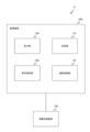
- FIG. 1 is a diagram illustrating an example of the configuration of a monitoring system according to a first embodiment.
- FIG. 2 is a diagram illustrating an example of a hardware configuration of a monitoring device according to the first embodiment.
- FIG. 4 is a diagram showing an example of a monitoring screen according to the first embodiment;
- FIG. 4 is a diagram showing an example of a monitoring screen according to the first embodiment;
- FIG. 4 is a diagram showing an example of a monitoring screen according to the first embodiment;
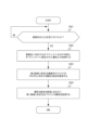
- 5 is a flowchart illustrating an example of a flow of processing by the monitoring device according to the first embodiment.
- FIG. 11 is a diagram illustrating an example of the configuration of a monitoring system according to a second embodiment.
- FIG. 13 is a diagram showing an example of information stored in a storage unit of a monitoring device according to a second embodiment;
- FIG. 11 is a diagram showing an example of a monitoring screen according to the second embodiment;
- FIG. 11 is a diagram showing an example of a monitoring screen according to the second embodiment;
- FIG. 11 is a diagram showing an example of a monitoring screen according to the second embodiment;
- FIG. 11 is a diagram showing an example of a monitoring screen according to the second embodiment;
- 13 is a flowchart showing an example of the flow of a process of calling up a registered name by a monitoring device according to a second embodiment.
- 10 is a flowchart showing an example of the flow of a setting and saving process of attributes and the like by a monitoring device according to a second embodiment.
- FIG. 13 is a diagram showing an example of a monitoring screen according to the third embodiment.
- FIG. 13 is a diagram illustrating an example of the configuration of a monitoring system according to a third embodiment.
- FIG. 13 is a diagram showing an example of a monitoring screen according to the third embodiment.
- FIG. 13 is a diagram showing an example of a monitoring screen according to the third embodiment.
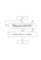
- 13 is a flowchart showing an example of the flow of processing for changing an area size by changing a boundary position performed by a monitoring device according to a third embodiment.
- FIG. 1 is a diagram showing an example of the configuration of a monitoring system according to a first embodiment.
- the monitoring system 1 includes a monitoring device 100 and an information collection device 200.
- the monitoring system 1 is a system that monitors a plurality of facilities in a building.
- the monitoring system 1 that monitors a transport system including a route (track) laid in a building, a cart that runs on the route, points, stations, and facilities that indicate a locked area, etc., will be described as an example.
- a locked area is an area where the entry and passage of a cart is restricted. Note that the monitoring system 1 is not limited to a transport system.
- the monitoring device 100 has a memory unit 110, a communication control unit 120, a reception unit 130, and a display control unit 140.
- the monitoring device 100 is a dedicated terminal for monitoring the equipment including the route and the carts in the transport system, or an information processing device such as a PC (Personal Computer).
- the information collection device 200 collects various information for each of the multiple facilities in the building and transmits it to the monitoring device 100. For example, the information collection device 200 collects information such as whether the route in the transport system is normal, congested, or down, as the status of the route, and transmits it to the monitoring device 100.
- the information collection device 200 also collects information such as the current position of each cart, the presence or absence of a transport command, abnormality, warning, etc., as the status of the carts in the transport system, and transmits it to the monitoring device 100.
- the information collection device 200 may be a controller installed in the transport system that manages each cart and assigns transport commands, or it may be a device that acquires various information from the controller or other devices.
- the information collection device 200 when configured to acquire various information from a controller or other devices, it may be configured as one unit with the monitoring device 100.
- the memory unit 110 stores (temporarily stores) various information about each of the multiple facilities in the building transmitted by the information collection device 200, various data required for processing by each part of the monitoring device 100, etc.
- the communication control unit 120 controls the transmission and reception of various information with the information collection device 200. For example, the communication control unit 120 acquires various information from the information collection device 200 and stores the acquired information in the memory unit 110.
- the display control unit 140 controls the display of a monitoring screen on a display device, the monitoring screen having a first area including a plurality of objects corresponding to each of the plurality of facilities, and a second area including names indicating each of the plurality of objects and attributes to be set for each object.
- the display control unit 140 generates image data representing the monitoring screen, and displays the generated monitoring screen on the display device.
- the display control unit 140 controls the display of a first area including a plurality of objects corresponding to each of the facilities indicating the route, the carts traveling on the route, points, stations, and lock areas, etc., on the display device for the monitoring screen displayed on the display device (output device 15 described later).
- the display control unit 140 controls the display of a second area including names indicating each of the plurality of objects and attributes such as colors to be set for each object, on the display device for the monitoring screen.
- the display control unit 140 controls the display of a monitoring screen including the first area and the second area in one window on the display device.
- the reception unit 130 receives input for changing attribute settings in response to operations on the second area.
- the user of the monitoring device 100 operates a first attribute setting section (e.g., a drop-down list that allows individual color settings, see FIG. 4, etc.) included in the second area to change attributes such as color of each of the multiple objects included in the first area using an input section (input device 14 described below) such as a mouse, keyboard, or touch panel.
- a first attribute setting section e.g., a drop-down list that allows individual color settings, see FIG. 4, etc.
- an input section input device 14 described below
- This causes the reception unit 130 to receive input for changing attribute settings such as color of each of the multiple objects included in the first area in response to operations on the first attribute setting section in the second area.
- the display control unit 140 controls the display of the monitoring screen on the display device in which the objects included in the first area have been changed in response to the input of attribute setting changes. Specifically, the display control unit 140 generates image data of the monitoring screen in which the colors, etc. of each object included in the first area have been changed in response to the input of attribute setting changes such as color by the reception unit 130, and controls the display of the generated monitoring screen on the display device.
- FIG. 2 is a diagram showing an example of the hardware configuration of a monitoring device according to the first embodiment.
- the monitoring device 100 is realized, for example, by a hardware configuration similar to that of a general-purpose computer.
- the monitoring device 100 executes a predetermined program (e.g., an information processing program) to realize a function of controlling the display on a display device of a monitoring screen including a first area and a second area in one window, in which an object included in the first area is changed in response to an operation on the second area.
- a predetermined program e.g., an information processing program
- the monitoring device 100 has a CPU (Central Processing Unit) 11, a ROM (Read Only Memory) 12, a RAM (Random Access Memory) 13, an input device 14, an output device 15, a communication device 16, and a storage device 17.
- the above components are connected by a bus 18.
- the CPU 11 is a processor that executes various processes, and deploys information processing programs stored in the storage device 17 etc. to the RAM 13 and executes them, controls the various components to perform input/output, and performs image processing for display control of the monitoring screen.
- the CPU 11 may be composed of one or more processors.
- the ROM 12 stores a start program that reads a startup program from the storage device 17 to the RAM 13.
- the RAM 13 stores various data as a working area for the CPU 11.
- the input device 14 is, for example, an input device such as a mouse or keyboard, which accepts input information as a signal and outputs it to the CPU 11.
- the output device 15 is, for example, a display device such as an LCD display, which displays and outputs various information based on signals from the CPU 11.
- the communication device 16 transmits and receives information to and from external devices via a network.
- the storage device 17 is, for example, a hard disk drive or flash memory.
- the storage device 17 stores programs (e.g., information processing programs) executed by the monitoring device 100, and an operating system.
- the program executed by the monitoring device 100 (e.g., an information processing program) is provided by being stored in a computer-readable recording medium such as a CD-ROM, flexible disk, CD-R, or DVD as a file in an installable or executable format.
- the program executed by the monitoring device 100 may also be provided by being stored on a computer connected to a network such as the Internet and downloaded via the network.
- the program executed by the monitoring device 100 may also be provided or distributed via a network such as the Internet.
- the program executed by the monitoring device 100 may also be provided by being pre-installed in ROM 12, etc.
- the information processing program includes at least a reception module that functions as the reception unit 130 and a display control module that functions as the display control unit 140.
- the CPU 11 as a processor reads out and executes the information processing program from the storage device 17 or the like, whereby each module is loaded onto the RAM 13, and the CPU 11 functions as the reception unit 130 and the display control unit 140.
- each function may be realized in part or in whole by hardware other than a processor.
- each function may be realized by cloud computing executed via a network.
- FIGS. 3 to 5 are diagrams showing examples of a monitoring screen according to the first embodiment.
- the monitoring screen 500 has a first area 510 including a plurality of objects corresponding to each of a plurality of pieces of equipment in a building, and a second area 520 including names indicating each of the plurality of objects and attributes to be set for each object.
- the first area 510 includes a point 512, a route 513, a station 514, a trolley 515, and a lock area 516 as objects corresponding to each of a plurality of pieces of equipment in the building.
- the first area 510 can be scrolled using scroll bars 511a and 511b.
- the second area 520 includes an adjustment bar 521 that allows the display magnification of each object in the first area 510 to be adjusted by moving the bar, and a text box 522a that allows the display magnification to be adjusted by inputting a numerical value.
- the second area 520 also includes a text box 522b that displays characters included in the first area 510 by inputting a numerical value corresponding to the display magnification.
- "30" is set in the text box 522a
- "40" is set in the text box 522b.
- the display control unit 140 controls so that the characters (or numerical values, etc.) included in the first area 510 are displayed. That is, in the example shown in FIG. 3, the display magnification is set to 30%, but when this display magnification becomes 40% or more, the characters (or numerical values, etc.) included in the first area 510 are displayed.
- the second area 520 also includes a check box 523a that allows the display of the points 512 included in the first area 510 to be switched between visible and invisible, and a check box 523b that allows the display of the route 513 to be switched between visible and invisible.
- the second area 520 includes a check box 523c that allows the display of the stations 514 included in the first area 510 to be switched between visible and invisible, and a check box 523d that allows the display of the trolleys 515 to be switched between visible and invisible.
- the second area 520 includes a check box 523e that allows the display of the lock area 516 included in the first area 510 to be switched between visible and invisible.
- the display control unit 140 controls the display and non-display of each object in the first area 510 according to the check status of the check boxes 523a to 523e in the second area 520.
- the second area 520 also includes a drop-down list 524a that allows the setting of a color, which is one of the attributes of the point 512 included in the first area 510.
- the second area 520 also includes drop-down lists 524b, 524c, and 524d that allow the setting of a color, which is one of the attributes of the route 513 included in the first area 510, for a normal route, a congested route, and a down route, respectively.
- the second area 520 also includes a drop-down list 524e that allows the setting of a color, which is one of the attributes of the station 514 included in the first area 510.
- the second area 520 also includes drop-down lists 524f, 524g, 524h, and 524i that allow the setting of a color, which is one of the attributes of the cart 515 included in the first area 510, for a cart with a transport command, a cart without a transport command, a cart in an abnormal state, and a cart in a warning state, respectively.
- the second area 520 also includes a drop-down list 524j that allows the user to set a color, which is one of the attributes of the lock area 516 included in the first area 510. Below, the drop-down lists 524a to 524j will simply be referred to as "drop-down lists 524" unless otherwise specified.
- an example is taken of changing the color setting of the trolley 515 included in the first area 510 (the trolley 515 without a transport command).
- the user performs an operation to change the setting of the drop-down list 524f using the input device 14 or the like.
- the reception unit 130 receives an input for changing the color setting, which is one of the attributes of the trolley 515 without a transport command, in response to the operation on the drop-down list 524f included in the second area 520.
- the display control unit 140 controls the display on the display device of the monitoring screen 500 in which the color of the trolley 515 included in the first area 510 has been changed in response to the input for changing the color setting of the trolley 515 without a transport command in the reception unit 130.
- step S101 the reception unit 130 judges whether or not an input for changing the attribute setting has been received. Specifically, the reception unit 130 judges whether or not an input for changing the color setting of each object included in the first area 510 has been received depending on whether or not an operation has been performed on each drop-down list 524 included in the second area 520. At this time, if the reception unit 130 accepts an input for changing the attribute setting (step S101: YES), the display control unit 140 controls the display of the monitoring screen 500 in which the object has been changed according to the setting change (step S102).
- the display control unit 140 controls the display of the monitoring screen 500 in which the color of the object included in the first area 510 corresponding to the input for changing the color setting has been changed on the display device.
- the reception unit 130 enters a state of waiting for reception of input for changing the attribute settings.
- the attribute settings included in the second area 520 are reflected in the objects included in the first area 510 on the monitoring screen 500 for monitoring. This allows the user to change the attribute settings while checking the display state of the objects in a single window. Therefore, the monitoring system 1 allows the user to easily recognize the display contents of the monitoring screen 500 after the settings have been made, improving user convenience.
- FIG. 7 is a diagram showing an example of the configuration of a monitoring system according to the second embodiment.
- the monitoring system 1a has a monitoring device 100a and an information collection device 200.
- the monitoring device 100a has a storage unit 110a, a communication control unit 120, a reception unit 130a, and a display control unit 140a.
- the storage unit 110a stores a combination of a name indicating an object corresponding to each of a plurality of pieces of equipment in a building and an attribute set to the object, in association with the registered name.
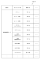
- FIG. 8 is a diagram showing an example of information stored in the storage unit of the monitoring device according to the second embodiment. As shown in FIG. 8, the storage unit 110a stores information on an "object name" indicating the name of an object included in the first area 510 and an "attribute" such as a color set to the object, in association with a "registered name” indicating these registered names.
- the storage unit 110a stores an object name "point” (point 512) and an attribute (e.g., color) "first color” set to the point 512, in association with the registered name "transport volume confirmation mode".
- the transport volume confirmation mode is associated with attributes set for each of the route (normal, congestion, route down), station, cart (no transport command, transport command, abnormal, warning), and locked area.
- the storage unit 110a may also store object names and attributes associated with other registered names. Additionally, the storage unit 110a may associate the same color with different objects.
- the reception unit 130a receives the input of the registered name. Specifically, the user of the monitoring device 100a operates a second attribute setting section (e.g., a drop-down list 525a for simultaneously setting a color based on pre-stored information and a save/set button 525b, see FIG. 10, etc.) included in the second area using the input device 14, etc., to change attributes such as the color of each of the multiple objects included in the first area. As a result, the reception unit 130a receives the input of the registered name included in the information stored in the storage unit 110a in response to the operation on the second attribute setting section in the second area.
- a second attribute setting section e.g., a drop-down list 525a for simultaneously setting a color based on pre-stored information and a save/set button 525b, see FIG. 10, etc.
- the display control unit 140a acquires the name and attributes corresponding to the registered name whose input has been accepted from the storage unit 110a.
- the display control unit 140a then changes the attribute settings corresponding to each of the multiple objects included in the second area, and changes the attributes of the objects included in the first area in accordance with the change in the attribute settings.
- the display control unit 140a acquires the object name and attributes corresponding to the registered name stored in the storage unit 110a based on the registered name whose input has been accepted, in response to the input of the registered name by the reception unit 130a.
- the display control unit 140a then changes the first attribute setting unit (e.g., a drop-down list 524 that allows individual color setting, see FIG.
- the reception unit 130a receives input of a new registration name for the attributes set for each of the multiple objects included in the second area.
- the reception unit 130a then stores the combination of name and attribute in the storage unit 110a in association with the new registration name that has been received.
- the user operates the attribute saving unit (e.g., "Save/Set button 525b" that allows the information of currently set attributes to be saved; see FIG. 12, etc.) and inputs the registration name.
- the reception unit 130a receives input of a new registered name, obtains attribute information set for each object when the input of the new registered name is received, and stores the combination of the object name and attribute in the storage unit 110a in association with the new registered name. In this way, it is possible to change the attributes of each object in response to the process of calling up the registered name, as described above.
- FIGS. 9 to 12 are diagrams showing examples of a monitoring screen according to the second embodiment.
- the second area 520 of the monitoring screen 500 according to the second embodiment includes, in addition to the elements described in the first embodiment, a drop-down list 525a that allows the user to call up a registered name stored in the storage unit 110a, and a save/set button 525b that allows the user to set the attributes of the object corresponding to the called-up registered name.
- the drop-down list 525a is displayed as "New Registration" by default, and at this time, the save/set button 525b acts as a trigger for saving the current attribute settings.
- the user operates the drop-down list 525a included in the second area 520, selects a registered name (here, the registered name "transport volume confirmation mode"), and presses the save/set button 525b.
- This causes the reception unit 130a to accept the input of the registered name "transport volume confirmation mode" selected in the drop-down list 525a.
- the display control unit 140a acquires from the memory unit 110a (see FIG.
- the display control unit 140a generates a monitoring screen 500 in which the attribute settings (the settings of the drop-down list 524) corresponding to each of the multiple objects included in the second area 520 are changed based on the object names and attributes acquired from the storage unit 110a, and controls the display of the generated monitoring screen 500 on the display device.
- attribute e.g., first color to tenth color
- the display control unit 140 also generates a monitoring screen 500 in which the colors of the objects included in the first area 510 (e.g., points 512, routes 513, stations 514, dollies 515, and lock areas 516) are changed in accordance with the change in the attribute settings (the settings of the drop-down list 524) included in the second area 520, and controls the display of the generated monitoring screen 500 on the display device.
- the colors of the objects included in the first area 510 e.g., points 512, routes 513, stations 514, dollies 515, and lock areas 516
- the user operates the drop-down list 524 to set the attribute to be saved. Then, the user performs an operation of pressing the save/set button 525b when the item of the drop-down list 525a included in the second area 520 is "New Registration".
- the reception unit 130a accepts the operation of new registration and notifies the display control unit 140a. Then, in response to the notification of new registration from the reception unit 130a, the display control unit 140a displays an input screen 530 in which a registration name can be input. The user performs an operation to input a new registration name and then save it (an operation to press the save button on the input screen 530).
- the reception unit 130a accepts the input of the new registration name, obtains information on the attributes (e.g., the color set in each drop-down list 524) set for each object in the second area 520 at this time, and stores the combination of the object name and the attribute in the storage unit 110a in association with the new registration name. If the user wishes to cancel input of the registration name on the input screen 530, the user presses the cancel button.
- the attributes e.g., the color set in each drop-down list 524
- FIG. 13 is a flowchart showing an example of the flow of a process for calling up a registered name by a monitoring device according to the second embodiment.
- the reception unit 130a determines whether input of a registered name has been received (step S201). Specifically, the reception unit 130a determines whether input of a registered name has been received depending on whether a registered name has been selected by operating the drop-down list 525a included in the second area 520 and whether the save/set button 525b has been pressed. At this time, if the reception unit 130a has received input of a registered name (step S201: YES), the display control unit 140a acquires the name indicating the object corresponding to the registered name and the attributes set for the object (step S202).
- the display control unit 140a acquires from the storage unit 110a (see FIG. 8) the object name (e.g., point, route (normal, congestion, route down), station, cart (no transport command, transport command, abnormal, warning), locked area) and attribute (e.g., first color to tenth color) corresponding to the registered name (e.g., transport volume confirmation mode, see FIG. 10) input received by the reception unit 130a.
- object name e.g., point, route (normal, congestion, route down), station, cart (no transport command, transport command, abnormal, warning), locked area
- attribute e.g., first color to tenth color
- the display control unit 140a changes the attribute settings corresponding to each of the multiple objects included in the second area (step S203). Specifically, the display control unit 140a generates a monitoring screen 500 in which the attribute settings (settings of the drop-down list 524) included in the second area 520 are changed based on the object names and attributes acquired from the storage unit 110a, and controls the display of the generated monitoring screen 500 on the display device. Next, the display control unit 140a changes the attributes of the objects included in the first area in accordance with the change in the attribute settings (step S204).
- the display control unit 140a generates a monitoring screen 500 in which the colors of the objects included in the first area 510 (e.g., points 512, routes 513, stations 514, dollies 515, and lock areas 516) are changed in accordance with the change in the attribute settings (settings of the drop-down list 524) included in the second area 520, and controls the display of the generated monitoring screen 500 on the display device.
- the accepting unit 130a enters a state of waiting for the input of the registration name to be accepted.
- FIG. 14 is a flowchart showing an example of the flow of attribute setting and saving processing by the monitoring device according to the second embodiment.
- the reception unit 130a judges whether or not input of a new registration name has been accepted (step S301). Specifically, when the item in the drop-down list 525a included in the second area 520 is "New Registration," the user presses the Save/Set button 525b. This causes the reception unit 130a to accept the operation for new registration, and the display control unit 140a displays the input screen 530 that allows the registration name to be entered (see FIG. 12). The reception unit 130a then judges whether or not input of a new registration name has been accepted depending on whether or not an operation to save the input of the new registration name has been performed on the input screen 530.
- the reception unit 130a when the reception unit 130a receives input of a new registration name (step S301: YES), it stores in the storage unit 110a a combination of the name indicating the object and the attributes set for the object in association with the new registration name received (step S302). Specifically, when a new registration name is entered on the input screen 530 and the Save button is pressed, the reception unit 130a receives the input of the new registration name and obtains information on the attributes (e.g., the colors set in each drop-down list 524) set for each object in the second area 520 at this time. The reception unit 130a then stores in the storage unit 110a a combination of the object name and the attributes in association with the new registration name received.
- the attributes e.g., the colors set in each drop-down list 52
- the monitoring system 1a has a storage unit 110a that stores a combination of an object name and attributes set for the object in association with a registered name, and in response to input of a registered name, the attribute settings for the object stored in the storage unit 110a are called up and reflected on the monitoring screen 500, so that the specified settings for the attributes can be implemented quickly, improving user convenience.
- the monitoring system 1a stores the attribute settings currently set for the object together with the registered name in the storage unit 110a, so that the specified settings for the attributes once set can be called up from the storage unit 110a and reflected on the monitoring screen 500, improving user convenience.
- the attributes included in the second area 520 (attributes set for each of the multiple objects) will be described.
- the color set for an object has been described as an example of one of the attributes.
- the attribute is not limited to color.
- the attributes may be shape, size, line thickness, overlapping order, transparency, font, blinking, etc., in addition to color. That is, the display control unit 140b (see FIG. 16) changes the attribute of the object included in the first area 510 according to an attribute indicating at least one of color, shape, size, line thickness, overlapping order, transparency, font, and blinking.
- the monitoring screen 500 includes a third attribute setting section (e.g., selection sections 527a to 527j that enable setting of shape, line thickness, etc.) that indicates an attribute of an object other than color.
- selection section 527a enables setting of the shape (including fill effect) of point 512 included in first area 510.
- Selection sections 527b, 527c, and 527d enable setting of the line thickness (including line type) of route 513 (normal, congestion, route down) included in first area 510.
- Selection section 527e enables setting of the shape (including fill effect) of station 514 included in first area 510.
- Selection units 527f, 527g, 527h, and 527i allow the shape (including fill effect) of the cart 515 (transport command received, transport command not received, abnormal, warning) included in the first area 510 to be set.
- Selection unit 527j allows the shape (including fill effect) of the lock area 516 included in the first area 510 to be set.
- the monitoring screen 500 includes a boundary line 540 indicating the boundary position between the first area 510 and the second area 520. Note that the first area 510 can be scrolled using a scroll bar 526, as described below.
- FIG. 16 is a diagram showing an example of the configuration of a monitoring system according to the third embodiment.
- the monitoring system 1b has a monitoring device 100b and an information collection device 200.
- the monitoring device 100b has a storage unit 110, a communication control unit 120, a reception unit 130b, and a display control unit 140b.
- FIG. 17A and FIG. 17B are diagrams showing examples of monitoring screens according to the third embodiment.
- the reception unit 130b receives an input for changing the boundary position between the first area and the second area on the monitoring screen. Specifically, the user of the monitoring device 100b performs an operation to change the boundary position between the first area 510 and the second area 520 using the input device 14 or the like. For example, the user of the monitoring device 100b performs an operation to move the boundary line 540 as shown by the block arrow using the input device 14 or the like (see FIG. 17A). As a result, the reception unit 130b receives a user operation to move the boundary line 540 on the monitoring screen 500, and notifies the display control unit 140b of movement information such as the amount of movement of the boundary line 540.
- the display control unit 140b changes the size of the first area and the second area in response to the input of the change in the boundary position. Specifically, the display control unit 140b receives movement information of the boundary 540 from the reception unit 130b, generates a monitoring screen 500 in which the sizes of the first area 510 and the second area 520 are changed based on the received movement information of the boundary 540, and controls the display of the generated monitoring screen 500 on the display device (see FIG. 17B). In addition, the display control unit 140b reflects the validity/invalidity of the scroll bar 526 in response to the movement of the boundary 540. That is, the boundary 540 shown in FIG. 17A may be movable only in one direction indicated by the block arrow, and the boundary 540 shown in FIG.
- 17B may be movable in both directions indicated by the block arrow. In other words, a limit may be set on the movement of the boundary 540 from the second area 520 to the first area 510.
- the scroll bar 526 may be always enabled, and there may be no restriction on the movement of the border 540 from the second area 520 to the first area 510.
- the reception unit 130b determines whether or not an input for changing the boundary position between the first area 510 and the second area 520 on the monitoring screen 500 has been received (step S401). Specifically, the reception unit 130b determines whether or not a user operation for moving the boundary line 540 indicating the boundary position between the first area 510 and the second area 520 on the monitoring screen 500 has been received.
- the display control unit 140b changes the size of the first area 510 and the second area 520 (step S402). Specifically, the reception unit 130b receives a user operation to move the boundary line 540 on the monitoring screen 500, and notifies the display control unit 140b of movement information such as the amount of movement of the boundary line 540.
- the display control unit 140b then receives the movement information of the boundary line 540 from the reception unit 130b, generates a monitoring screen 500 in which the sizes of the first area 510 and the second area 520 have been changed based on the received movement information of the boundary line 540, and controls the display of the generated monitoring screen 500 on the display device.
- the reception unit 130b if the reception unit 130b has not received an input to change the boundary position (step S401: NO), the reception unit 130b enters a state of waiting for reception of an input to change the boundary position.
- monitoring system 1b changes the attributes of objects included in first area 510 according to attributes indicating at least one of color, shape, size, line thickness, overlay order, transparency, font, and blinking, so that the user can easily recognize the display contents of monitoring screen 500 reflecting the settings of multiple attributes at a glance. Furthermore, monitoring system 1b changes the sizes of first area 510 and second area 520 according to a change in the position of boundary line 540 between first area 510 and second area 520 on monitoring screen 500, so that second area 520 including setting items for object attributes does not interfere with the display of first area 510 including the object.
- the monitoring device 100 includes, for example, a computer system.
- the monitoring device 100 reads out an information processing program stored in the storage unit 110 or the like, and executes various processes according to the information processing program.
- the information processing program causes the computer to, for example, control the display on a display device of a monitoring screen having a first area including a plurality of objects corresponding to each of a plurality of pieces of equipment in a building, and a second area including names indicating each of the plurality of objects and attributes to be set for each object, accept input of attribute setting changes in response to an operation on the second area, and control the display on the display device of a monitoring screen in which the objects included in the first area have been changed in response to the input of attribute setting changes.
- the information processing program may be provided by being recorded on a computer-readable storage medium.
- a monitoring system for monitoring a plurality of facilities in a building a display control unit that controls display on a display device of a monitoring screen having a first area including a plurality of objects corresponding to each of the plurality of facilities and a second area including names indicating each of the plurality of objects and attributes to be set for each object; a reception unit that receives an input for changing a setting of the attribute in response to an operation on the second area, The display control unit controls the display of the monitoring screen on the display device in which the objects included in the first area have been changed in response to an input of a change to the attribute settings.
- (Supplementary Note 2) A storage unit that stores a combination of a name indicating the object and the attribute set for the object in association with a registered name, The reception unit receives an input of the registration name, The monitoring system described in Appendix 1, wherein the display control unit retrieves from the memory unit the name and the attributes corresponding to the registered name whose input has been accepted, changes the settings of the attributes corresponding to each of the plurality of objects included in the second area, and changes the attributes of the objects included in the first area in accordance with the change in the attribute settings.
- Appendix 3 The monitoring system described in Appendix 2, wherein the reception unit receives input of a new registered name for the attributes set for each of the plurality of objects included in the second area, and stores the combination of the name and the attribute in the memory unit in correspondence with the new registered name whose input has been received.
- Appendix 4 A monitoring system described in any one of Appendix 1 to Appendix 3, wherein the display control unit changes the attributes of the object included in the first area depending on the attributes indicating at least one of color, shape, size, line thickness, overlapping order, transparency, font, and blinking.
- the reception unit receives an input for changing a boundary position between the first area and the second area on the monitoring screen,
- the monitoring system according to any one of claims 1 to 4, wherein the display control unit changes the size of the first area and the second area in response to an input for changing the boundary position.
- Controlling the display of a monitoring screen on a display device the monitoring screen having a first area including a plurality of objects corresponding to each of a plurality of pieces of equipment in a building, and a second area including names indicating each of the plurality of objects and attributes to be set for each of the objects; receiving an input for changing a setting of the attribute in response to an operation on the second area; and controlling display of the monitoring screen on the display device in which the object included in the first area has been changed in response to input of a change to the attribute setting.
- Appendix 7 A computer Controlling the display of a monitoring screen on a display device, the monitoring screen having a first area including a plurality of objects corresponding to each of a plurality of pieces of equipment in a building, and a second area including names indicating each of the plurality of objects and attributes to be set for each of the objects; receiving an input for changing a setting of the attribute in response to an operation on the second area; and controlling, on the display device, a display of the monitoring screen in which the object included in the first area has been changed in response to an input of a change to the attribute setting.
- the monitoring system 1 that monitors a transport system including a route (track) laid inside a building, carts that run on the route, points, stations, lock areas, and other equipment has been described as an example.
- the present invention is not limited to this.
- the present invention can be similarly applied to a stocker/storage system that includes shelves, cranes, ports, and other equipment (constituent units), and a conveyor system that includes arms, shelves, and other equipment (constituent units).
- Monitoring system 100 Monitoring device 110
- Storage unit 120 Communication control unit 130
- Reception unit 140 Wireless Control unit 200
Landscapes
- Engineering & Computer Science (AREA)
- Theoretical Computer Science (AREA)
- Physics & Mathematics (AREA)
- General Physics & Mathematics (AREA)
- Computer Hardware Design (AREA)
- General Engineering & Computer Science (AREA)
- Business, Economics & Management (AREA)
- Human Resources & Organizations (AREA)
- Human Computer Interaction (AREA)
- Strategic Management (AREA)
- Economics (AREA)
- Entrepreneurship & Innovation (AREA)
- Educational Administration (AREA)
- Game Theory and Decision Science (AREA)
- Development Economics (AREA)
- Marketing (AREA)
- Operations Research (AREA)
- Quality & Reliability (AREA)
- Tourism & Hospitality (AREA)
- General Business, Economics & Management (AREA)
- Testing And Monitoring For Control Systems (AREA)
Abstract
【課題】監視画面に表示されるオブジェクトの属性を設定する際に、設定後の監視画面の表示内容を容易に認識させること。 【解決手段】監視システムは、複数の設備のそれぞれに対応する複数のオブジェクトを含む第1領域と、複数のオブジェクトのそれぞれを示す名称及び各オブジェクトに設定する属性を含む第2領域とを有する監視画面の表示装置への表示を制御する表示制御部と、第2領域に対する操作に応じて属性の設定変更の入力を受け付ける受付部と、を有し、表示制御部は、属性の設定変更の入力に応じて、第1領域に含まれるオブジェクトを変更した監視画面の表示装置への表示を制御する。
Description
本発明は、監視システム、情報処理方法、及び情報処理プログラムに関する。
従来、工場内における複数の設備を監視する監視システムが知られている。例えば、特許文献1では、搬送台車の走行状況について、搬送台車や搬送台車が走行する軌道等の設備に対応するオブジェクトを色分けした監視画面(モニタリング画面)を表示する技術が開示されている。
上記のような技術では、監視画面に表示されるオブジェクトの色分け等の属性は、監視画面とは異なるウィンドウで表示される設定画面を用いて予め設定される。かかる場合、ユーザは、設定画面において属性を設定する際、監視画面がどのように表示されるのかが想像しづらく、表示される監視画面がユーザの想定通りにならないおそれがある。そこで、監視画面とは異なるウィンドウで表示される設定画面にプレビュー機能を付加することが考えられるが、構成が複雑になるため好ましくない。
本発明は、監視画面に表示されるオブジェクトの属性を設定する際に、設定後の監視画面の表示内容を容易に認識させることができる監視システム、情報処理方法、及び情報処理プログラムを提供する。
本発明の態様に係る監視システムは、建屋内における複数の設備を監視する監視システムであって、複数の設備のそれぞれに対応する複数のオブジェクトを含む第1領域と、複数のオブジェクトのそれぞれを示す名称及び各オブジェクトに設定する属性を含む第2領域とを有する監視画面の表示装置への表示を制御する表示制御部と、第2領域に対する操作に応じて属性の設定変更の入力を受け付ける受付部と、を有し、表示制御部は、属性の設定変更の入力に応じて、第1領域に含まれるオブジェクトを変更した監視画面の表示装置への表示を制御する。
本発明の態様に係る情報処理方法は、建屋内における複数の設備のそれぞれに対応する複数のオブジェクトを含む第1領域と、複数のオブジェクトのそれぞれを示す名称及びオブジェクトに設定する属性を含む第2領域とを有する監視画面の表示装置への表示を制御することと、第2領域に対する操作に応じて属性の設定変更の入力を受け付けることと、属性の設定変更の入力に応じて、第1領域に含まれるオブジェクトを変更した監視画面の表示装置への表示を制御することと、を含む。
本発明の態様に係る情報処理プログラムは、コンピュータに、建屋内における複数の設備のそれぞれに対応する複数のオブジェクトを含む第1領域と、複数のオブジェクトのそれぞれを示す名称及びオブジェクトに設定する属性を含む第2領域とを有する監視画面の表示装置への表示を制御することと、第2領域に対する操作に応じて属性の設定変更の入力を受け付けることと、属性の設定変更の入力に応じて、第1領域に含まれるオブジェクトを変更した監視画面の表示装置への表示を制御することと、を実行させる。
本発明の態様に係る監視システム、情報処理方法、及び情報処理プログラムによれば、ユーザは、モニタリングの監視画面上でオブジェクトの表示状態を確認しながらオブジェクトの属性を変更させる操作を行うので、設定後の監視画面の表示内容を容易に認識することができる。これにより、ユーザの利便性を向上させることができる。
また、上記態様の監視システムにおいて、オブジェクトを示す名称と、オブジェクトに設定された属性との組み合わせを、登録名に対応付けて記憶する記憶部を有し、受付部が、登録名の入力を受け付け、表示制御部が、入力が受け付けられた登録名に対応する名称と属性とを記憶部から取得し、第2領域に含まれる複数のオブジェクトのそれぞれに対応する属性の設定を変更するとともに、属性の設定の変更に合わせて、第1領域に含まれるオブジェクトの属性を変更してもよい。この態様によれば、予め保存された属性の設定を呼び出して、監視画面のオブジェクトの属性を変更するので、属性に関する所定の設定を迅速に実施することができ、ユーザの利便性を向上させることができる。また、上記態様の監視システムにおいて、受付部が、第2領域に含まれる複数のオブジェクトのそれぞれに設定された属性に対する新規の登録名の入力を受け付け、名称と、属性との組み合わせを、入力を受け付けた新規の登録名に対応付けて記憶部に格納してもよい。この態様によれば、属性に関する所定の設定を記憶させることで、一度設定した属性に関する所定の設定を呼び出して反映させることができ、ユーザの利便性を向上させることができる。また、上記態様の監視システムにおいて、表示制御部が、色、形状、大きさ、線の太さ、重ね合わせ順、透明度、フォント、及び点滅のうち少なくとも1つを示す属性に応じて、第1領域に含まれるオブジェクトの属性を変更してもよい。この態様によれば、オブジェクトに関する種々の属性について、モニタリングの監視画面上でオブジェクトの表示状態を確認しながらオブジェクトの属性を変更させる操作を行うので、複数の属性の設定を反映させた監視画面の表示内容を一度で容易に認識することができる。また、上記態様の監視システムにおいて、受付部が、監視画面上における第1領域と第2領域との境界位置の変更の入力を受け付け、表示制御部が、境界位置の変更の入力に応じて、第1領域と第2領域とのサイズを変更してもよい。この態様によれば、オブジェクトを含む第1領域の表示と、オブジェクトの属性の設定項目を含む第2領域の表示との境界を変更できるので、第2領域を第1領域の表示の妨げにならないようにすることができる。
以下、実施形態について図面を参照して説明する。本発明は、以下で説明する形態に限定されない。図面では、実施形態を説明するために、一部分を拡大、縮小、又は強調して記載する等、縮尺を適宜変更して表現される場合がある。
[第1実施形態]
図1は、第1実施形態に係る監視システムの構成例を示す図である。図1に示すように、監視システム1は、監視装置100と、情報収集装置200とを有する。監視システム1は、建屋内における複数の設備を監視するシステムである。本実施形態では、建屋内に敷設されたルート(軌道)、ルートを走行する台車、ポイント、ステーション、及びロックエリア等を示す設備を含む搬送システムを監視する監視システム1を例に挙げて説明する。ロックエリアとは、台車の進入・通過が規制される領域である。なお、監視システム1は、搬送システムに限定されない。
図1は、第1実施形態に係る監視システムの構成例を示す図である。図1に示すように、監視システム1は、監視装置100と、情報収集装置200とを有する。監視システム1は、建屋内における複数の設備を監視するシステムである。本実施形態では、建屋内に敷設されたルート(軌道)、ルートを走行する台車、ポイント、ステーション、及びロックエリア等を示す設備を含む搬送システムを監視する監視システム1を例に挙げて説明する。ロックエリアとは、台車の進入・通過が規制される領域である。なお、監視システム1は、搬送システムに限定されない。
監視装置100は、記憶部110と、通信制御部120と、受付部130と、表示制御部140とを有する。監視装置100は、搬送システムにおけるルートや台車等を含む設備のモニタリングのための専用端末、又はPC(Personal Computer)等の情報処理装置である。情報収集装置200は、建屋内における複数の設備のそれぞれに対する各種情報を収集し、監視装置100に送信する。例えば、情報収集装置200は、搬送システムにおけるルートの状況として、正常であるか、渋滞しているか、ダウンしているか等の情報を収集し、監視装置100に送信する。また、情報収集装置200は、搬送システムにおける台車の状況として、各台車の現在位置、搬送指令の有無、異常、警告等の情報を収集し、監視装置100に送信する。情報収集装置200は、搬送システムに設置され、各台車を管理し、搬送指令を割り付けるコントローラ等であってもよいし、該コントローラや他の機器から各種情報を取得する装置であってもよい。なお、情報収集装置200は、コントローラや他の機器から各種情報を取得する構成とする場合、監視装置100と一体の構成であってもよい。
記憶部110は、情報収集装置200によって送信された建屋内における複数の設備のそれぞれに対する各種情報や、監視装置100の各部の処理に要する各種データ等を記憶(一時記憶)する。通信制御部120は、情報収集装置200との間における各種情報の送受信を制御する。例えば、通信制御部120は、情報収集装置200から各種情報を取得し、取得した各種情報を記憶部110に格納する。
表示制御部140は、複数の設備のそれぞれに対応する複数のオブジェクトを含む第1領域と、複数のオブジェクトのそれぞれを示す名称及び各オブジェクトに設定する属性を含む第2領域とを有する監視画面の表示装置への表示を制御する。表示制御部140は、監視画面を表す画像データを生成し、生成した監視画面を表示装置に表示させる。具体的には、表示制御部140は、監視装置100の表示装置(後述する出力装置15)に表示される監視画面について、ルート、ルートを走行する台車、ポイント、ステーション、及びロックエリア等を示す設備のそれぞれに対応する複数のオブジェクトを含む第1領域の表示装置への表示を制御する。加えて、表示制御部140は、監視画面について、複数のオブジェクトのそれぞれを示す名称及び各オブジェクトに設定する色等の属性を含む第2領域の表示装置への表示を制御する。表示制御部140は、1のウィンドウ内に第1領域と第2領域とを含む監視画面の表示装置への表示を制御する。
受付部130は、第2領域に対する操作に応じて属性の設定変更の入力を受け付ける。具体的には、監視装置100のユーザは、マウスやキーボード、タッチパネル等の入力部(後述する入力装置14)を用いて、第1領域に含まれる複数のオブジェクトのそれぞれの色等の属性を変更するために、第2領域に含まれる第1属性設定部(例、個別に色を設定可能とするドロップダウンリスト、図4等参照)を操作する。これにより、受付部130は、第2領域での第1属性設定部に対する操作に応じて、第1領域に含まれる複数のオブジェクトのそれぞれの色等の属性の設定変更の入力を受け付ける。
表示制御部140は、属性の設定変更の入力に応じて、第1領域に含まれるオブジェクトを変更した監視画面の表示装置への表示を制御する。具体的には、表示制御部140は、受付部130による色等の属性の設定変更の入力に応じて、第1領域に含まれる各オブジェクトの色等を変更した監視画面の画像データを生成し、生成した監視画面の表示装置への表示を制御する。
図2は、第1実施形態に係る監視装置のハードウェア構成例を示す図である。監視装置100は、例えば、汎用のコンピュータ等と同様のハードウェア構成により実現される。監視装置100は、所定のプログラム(例、情報処理プログラム)を実行することにより、第1領域と第2領域とを1のウィンドウに含む監視画面について、第2領域に対する操作に応じて第1領域に含まれるオブジェクトを変更した監視画面の表示装置への表示を制御する機能を実現する。
監視装置100は、CPU(Central Processing Unit)11と、ROM(Read Only Memory)12と、RAM(Random Access Memory)13と、入力装置14と、出力装置15と、通信装置16と、記憶装置17とを有する。上記各部は、バス18により接続される。CPU11は、各種処理を実行するプロセッサであり、記憶装置17等に記憶された情報処理プログラムをRAM13に展開して実行し、各部を制御して入出力を行ったり、監視画面の表示制御のための画像処理を行ったりする。CPU11は、1又は複数のプロセッサにより構成されてもよい。ROM12は、起動用プログラムを記憶装置17からRAM13に読み出すスタートプログラムを記憶する。RAM13は、CPU11の作業領域として各種データを記憶する。
入力装置14は、例えば、マウスやキーボード等の入力デバイスであり、操作入力された情報を信号として受け付けてCPU11に出力する。出力装置15は、例えば、液晶ディスプレイ等の表示装置であり、CPU11からの信号に基づいて各種情報を表示出力する。通信装置16は、ネットワークを介して外部の装置と情報を送受信する。記憶装置17は、例えば、ハードディスクドライブ又はフラッシュメモリ等である。記憶装置17は、監視装置100で実行されるプログラム(例、情報処理プログラム)、及びオペレーティングシステムを記憶する。
監視装置100で実行されるプログラム(例、情報処理プログラム)は、インストール可能な形式又は実行可能な形式のファイルでCD-ROM、フレキシブルディスク、CD-R、又はDVD等のコンピュータで読み取り可能な記録媒体に記憶されて提供される。また、監視装置100で実行されるプログラムを、インターネット等のネットワークに接続されたコンピュータ上に格納し、ネットワーク経由でダウンロードさせることにより提供する構成としてもよい。また、監視装置100で実行されるプログラムを、インターネット等のネットワーク経由で提供又は配布する構成としてもよい。また、監視装置100で実行されるプログラムを、ROM12等に予め組み込んで提供する構成としてもよい。
情報処理プログラムは、少なくとも、受付部130として機能する受付モジュールと、表示制御部140として機能する表示制御モジュールとを含む。監視装置100は、プロセッサとしてのCPU11が記憶装置17等から情報処理プログラムを読み出して実行することにより、各モジュールがRAM13上にロードされ、CPU11が、受付部130及び表示制御部140として機能する。なお、各機能は、一部又は全てがプロセッサ以外のハードウェアにより実現されてもよい。また、各機能は、ネットワークを経由して実行されるクラウドコンピューティングにより実現されてもよい。
図3~図5は、第1実施形態に係る監視画面の例を示す図である。図3に示すように、監視画面500は、建屋内における複数の設備のそれぞれに対応する複数のオブジェクトを含む第1領域510と、複数のオブジェクトのそれぞれを示す名称及び各オブジェクトに設定する属性を含む第2領域520とを有する。例えば、第1領域510は、建屋内における複数の設備のそれぞれに対応するオブジェクトとして、ポイント512、ルート513、ステーション514、台車515、及びロックエリア516を含む。第1領域510は、スクロールバー511a、511bによりスクロール表示が可能である。
例えば、第2領域520は、第1領域510内の各オブジェクトの表示倍率について、バーの移動により調整可能とする調整バー521と、数値の入力により調整可能とするテキストボックス522aとを含む。また、第2領域520は、第1領域510に含まれる文字について、表示倍率に対応する数値の入力により文字を表示させるテキストボックス522bを含む。図3に示す例では、テキストボックス522aに「30」が設定されており、テキストボックス522bに「40」が設定されている。表示制御部140は、テキストボックス522aに「40」以上の数値が設定された場合に、第1領域510に含まれる文字(又は数値等)を表示するように制御する。すなわち、図3に示す例では、表示倍率を30パーセントとしているが、この表示倍率が40パーセント以上となった場合に、第1領域510に含まれる文字(又は数値等)が表示されることとなる。
また、第2領域520は、第1領域510に含まれるポイント512の表示と非表示とを切り替え可能とするチェックボックス523aと、ルート513の表示と非表示とを切り替え可能とするチェックボックス523bとを含む。加えて、第2領域520は、第1領域510に含まれるステーション514の表示と非表示とを切り替え可能とするチェックボックス523cと、台車515の表示と非表示とを切り替え可能とするチェックボックス523dとを含む。さらに、第2領域520は、第1領域510に含まれるロックエリア516の表示と非表示とを切り替え可能とするチェックボックス523eとを含む。表示制御部140は、第2領域520におけるチェックボックス523a~チェックボックス523eのチェック状況に応じて、第1領域510における各オブジェクトの表示と非表示とを制御する。
また、第2領域520は、第1領域510に含まれるポイント512の属性の一つである色を設定可能とするドロップダウンリスト524aを含む。また、第2領域520は、第1領域510に含まれるルート513の属性の一つである色を、正常であるルート、渋滞しているルート、及びダウンしているルートのそれぞれに設定可能とするドロップダウンリスト524b、524c、524dを含む。また、第2領域520は、第1領域510に含まれるステーション514の属性の一つである色を設定可能とするドロップダウンリスト524eを含む。また、第2領域520は、第1領域510に含まれる台車515の属性の一つである色を、搬送指令がある台車、搬送指令がない台車、異常状態である台車、及び警告状態である台車のそれぞれに設定可能とするドロップダウンリスト524f、524g、524h、524iを含む。また、第2領域520は、第1領域510に含まれるロックエリア516の属性の一つである色を設定可能とするドロップダウンリスト524jを含む。以下では、各ドロップダウンリスト524a~524jについて、特に区別しない場合、単に「ドロップダウンリスト524」と呼ぶ。
ここで、第1領域510に含まれる台車515(搬送指令のない台車515)の色の設定を変更する場合を例に挙げる。図4に示すように、ユーザは、入力装置14等を用いて、ドロップダウンリスト524fの設定を変更する操作を行う。これにより、受付部130は、第2領域520に含まれるドロップダウンリスト524fに対する操作に応じて、搬送指令のない台車515の属性の一つである色の設定変更の入力を受け付ける。これにより、図5に示すように、表示制御部140は、受付部130における搬送指令のない台車515の色の設定変更の入力に応じて、第1領域510に含まれる台車515の色を変更した監視画面500の表示装置への表示を制御する。
図6は、第1実施形態に係る監視装置による処理の流れの例を示すフローチャートである。図6に示すように、受付部130は、属性の設定変更の入力を受け付けたか否かを判定する(ステップS101)。具体的には、受付部130は、第2領域520に含まれる各ドロップダウンリスト524に対する操作の有無に応じて、第1領域510に含まれる各オブジェクトの色の設定を変更する入力を受け付けたか否かを判定する。このとき、受付部130によって属性の設定変更の入力が受け付けられた場合に(ステップS101:YES)、表示制御部140は、設定変更に応じてオブジェクトを変更した監視画面500の表示を制御する(ステップS102)。具体的には、表示制御部140は、ユーザによる入力装置14等を用いたドロップダウンリスト524に対する操作により、受付部130によって色の設定変更の入力が受け付けられた場合に、色の設定変更の入力に対応する第1領域510に含まれるオブジェクトの色を変更した監視画面500の表示装置への表示を制御する。一方、受付部130は、属性の設定変更の入力が受け付けられていない場合に(ステップS101:NO)、属性の設定変更の入力の受け付け待ちの状態となる。
上述したように、監視システム1では、モニタリングのための監視画面500にて、第2領域520に含まれる属性の設定を、第1領域510に含まれるオブジェクトに反映させる。これにより、ユーザは、1つのウィンドウでオブジェクトの表示状態を確認しながら属性の設定を変更することができる。従って、監視システム1は、設定後の監視画面500の表示内容をユーザに容易に認識させ、ユーザの利便性を向上させることができる。
[第2実施形態]
第2実施形態では、上述した実施形態と同様の構成については同一の符号を付し、同様の構成についての詳細な説明を省略する場合がある。
第2実施形態では、上述した実施形態と同様の構成については同一の符号を付し、同様の構成についての詳細な説明を省略する場合がある。
図7は、第2実施形態に係る監視システムの構成例を示す図である。図7に示すように、監視システム1aは、監視装置100aと、情報収集装置200とを有する。監視装置100aは、記憶部110aと、通信制御部120と、受付部130aと、表示制御部140aとを有する。
記憶部110aは、建屋内における複数の設備のそれぞれに対応するオブジェクトを示す名称と、オブジェクトに設定された属性との組み合わせを、登録名に対応付けて記憶する。図8は、第2実施形態に係る監視装置の記憶部に記憶される情報例を示す図である。図8に示すように、記憶部110aは、第1領域510に含まれるオブジェクトの名称を示す「オブジェクト名」と、該オブジェクトに設定される色等の「属性」との情報を、これらの登録名称を示す「登録名」に対応付けて記憶する。例えば、記憶部110aは、登録名「輸送量確認モード」に対応付けて、オブジェクト名「ポイント」(ポイント512)と、該ポイント512に設定される属性(例、色)「第1色」とを記憶する。また、このほか、輸送量確認モードには、ルート(正常、渋滞、ルートダウン)、ステーション、台車(搬送指令なし、搬送指令あり、異常、警告)、及びロックエリアのそれぞれに対して設定される属性が対応付けられる。なお、記憶部110aには、他の登録名についても、オブジェクト名と属性とが対応付けて記憶されてもよい。また、記憶部110aには、異なるオブジェクトで同一の色が対応付けられていてもよい。
受付部130aは、登録名の入力を受け付ける。具体的には、監視装置100aのユーザは、入力装置14等を用いて、第1領域に含まれる複数のオブジェクトのそれぞれの色等の属性を変更するために、第2領域に含まれる第2属性設定部(例、予め記憶された情報をもとに一斉に色を設定するドロップダウンリスト525aや保存/設定ボタン525b等、図10等参照)を操作する。これにより、受付部130aは、第2領域での第2属性設定部に対する操作に応じて、記憶部110aに記憶された情報に含まれる登録名の入力を受け付ける。
表示制御部140aは、入力が受け付けられた登録名に対応する名称と属性とを記憶部110aから取得する。そして、表示制御部140aは、第2領域に含まれる複数のオブジェクトのそれぞれに対応する属性の設定を変更するとともに、属性の設定の変更に合わせて、第1領域に含まれるオブジェクトの属性を変更する。具体的には、表示制御部140aは、受付部130aによる登録名の入力に応じて、入力が受け付けられた登録名をもとに、記憶部110aに記憶された登録名に対応するオブジェクト名と、属性とを取得する。そして、表示制御部140aは、取得したオブジェクト名と属性とをもとに、第2領域に含まれる複数のオブジェクトのそれぞれに対応する第1属性設定部(例、個別に色を設定可能とするドロップダウンリスト524、図9等参照)を変更するとともに、色等の属性の設定の変更に合わせて、第1領域に含まれる各オブジェクトの色等を変更した監視画面を生成し、生成した監視画面の表示装置への表示を制御する。
また、本実施形態では、上記の登録名の呼び出し処理に応じた各オブジェクトの属性の変更のために、登録名、オブジェクト名、及び属性の設定を予め保存することが可能である。以下に、属性等の設定保存処理について説明する。
受付部130aは、第2領域に含まれる複数のオブジェクトのそれぞれに設定された属性に対する新規の登録名の入力を受け付ける。そして、受付部130aは、名称と、属性との組み合わせを、入力を受け付けた新規の登録名に対応付けて記憶部110aに格納する。具体的には、ユーザは、第2領域において、複数のオブジェクトのそれぞれに現在設定されている色等の属性を保存するために、属性保存部(例、現在設定されている属性の情報を保存可能とする「保存/設定ボタン525b」、図12等参照)を操作し、登録名の入力を行う。
そして、受付部130aは、新規の登録名の入力を受け付け、新規の登録名の入力を受け付けたときに各オブジェクトに設定されている属性の情報を取得し、オブジェクト名と、属性との組み合わせを、新規の登録名に対応付けて記憶部110aに格納する。これらにより、上記のように、登録名の呼び出し処理に応じた各オブジェクトの属性の変更を実現することができる。
図9~図12は、第2実施形態に係る監視画面の例を示す図である。図9に示すように、第2実施形態に係る監視画面500の第2領域520は、第1実施形態で説明した要素に加えて、記憶部110aに記憶された登録名の呼び出しを可能とするドロップダウンリスト525aと、呼び出した登録名に対応するオブジェクトの属性の設定の実行を可能とする保存/設定ボタン525bとを含む。また、ドロップダウンリスト525aはデフォルトでは「新規登録」と表示されており、このとき、保存/設定ボタン525bは現在の属性の設定を保存するトリガとしての役割を担う。
図10及び図11を用いて、登録名の呼び出し処理の例を説明する。図10に示すように、ユーザは、第2領域520に含まれるドロップダウンリスト525aを操作し、登録名(ここでは、登録名「輸送量確認モード」)を選択して、保存/設定ボタン525bを押下する操作を行う。これにより、受付部130aは、ドロップダウンリスト525aにおいて選択された登録名「輸送量確認モード」の入力を受け付ける。そして、表示制御部140aは、受付部130aにより入力が受け付けられた登録名「輸送量確認モード」に対応するオブジェクト名(例、ポイント、ルート(正常、渋滞、ルートダウン)、ステーション、台車(搬送指令なし、搬送指令あり、異常、警告)、ロックエリア)と属性(例、第1色~第10色)とを記憶部110a(図8参照)から取得する。続いて、図11に示すように、表示制御部140aは、記憶部110aから取得したオブジェクト名と属性とをもとに、第2領域520に含まれる複数のオブジェクトのそれぞれに対応する属性の設定(ドロップダウンリスト524の設定)を変更した監視画面500を生成し、生成した監視画面500の表示装置への表示を制御する。また、表示制御部140は、第2領域520に含まれる属性の設定(ドロップダウンリスト524の設定)の変更に合わせて、第1領域510に含まれるオブジェクト(例、ポイント512、ルート513、ステーション514、台車515、ロックエリア516)の色を変更した監視画面500を生成し、生成した監視画面500の表示装置への表示を制御する。
図12を用いて、属性等の設定保存処理の例を説明する。図12に示すように、ユーザは、ドロップダウンリスト524を操作し、保存させたい属性の設定とする。そして、ユーザは、第2領域520に含まれるドロップダウンリスト525aの項目が「新規登録」である状態において、保存/設定ボタン525bを押下する操作を行う。これにより、受付部130aは、新規登録する操作を受け付け、表示制御部140aに通知する。そして、表示制御部140aは、受付部130aからの新規登録の通知に応じて、登録名を入力可能とする入力画面530を表示する。ユーザは、新規の登録名を入力したうえで保存させる操作(入力画面530の保存ボタンを押下する操作)を行う。これにより、受付部130aは、新規の登録名の入力を受け付け、このときに第2領域520において各オブジェクトに設定されている属性(例、各ドロップダウンリスト524に設定されている色)の情報を取得し、オブジェクト名と、属性との組み合わせを、新規の登録名に対応付けて記憶部110aに格納する。なお、ユーザは、入力画面530において登録名の入力を中止する場合、キャンセルボタンを押下する操作を行う。
図13は、第2実施形態に係る監視装置による登録名の呼び出し処理の流れの例を示すフローチャートである。図13に示すように、受付部130aは、登録名の入力を受け付けたか否かを判定する(ステップS201)。具体的には、受付部130aは、第2領域520に含まれるドロップダウンリスト525aに対する操作により登録名が選択され、保存/設定ボタン525bの押下操作の有無に応じて、登録名の入力を受け付けたか否かを判定する。このとき、受付部130aによって登録名の入力が受け付けられた場合に(ステップS201:YES)、表示制御部140aは、登録名に対応するオブジェクトを示す名称とオブジェクトに設定された属性とを取得する(ステップS202)。具体的には、表示制御部140aは、受付部130aにより入力が受け付けられた登録名(例、輸送量確認モード、図10参照)に対応するオブジェクト名(例、ポイント、ルート(正常、渋滞、ルートダウン)、ステーション、台車(搬送指令なし、搬送指令あり、異常、警告)、ロックエリア)と属性(例、第1色~第10色)とを記憶部110a(図8参照)から取得する。
そして、表示制御部140aは、第2領域に含まれる複数のオブジェクトのそれぞれに対応する属性の設定を変更する(ステップS203)。具体的には、表示制御部140aは、記憶部110aから取得したオブジェクト名と属性とをもとに、第2領域520に含まれる属性の設定(ドロップダウンリスト524の設定)を変更した監視画面500を生成し、生成した監視画面500の表示装置への表示を制御する。続いて、表示制御部140aは、属性の設定の変更に合わせて、第1領域に含まれるオブジェクトの属性を変更する(ステップS204)。具体的には、表示制御部140aは、第2領域520に含まれる属性の設定(ドロップダウンリスト524の設定)の変更に合わせて、第1領域510に含まれるオブジェクト(例、ポイント512、ルート513、ステーション514、台車515、ロックエリア516)の色を変更した監視画面500を生成し、生成した監視画面500の表示装置への表示を制御する。一方、受付部130aは、登録名の入力を受け付けられていない場合に(ステップS201:NO)、登録名の入力の受け付け待ちの状態となる。
図14は、第2実施形態に係る監視装置による属性等の設定保存処理の流れの例を示すフローチャートである。図14に示すように、受付部130aは、新規の登録名の入力を受け付けたか否かを判定する(ステップS301)。具体的には、ユーザは、第2領域520に含まれるドロップダウンリスト525aの項目が「新規登録」である状態において、保存/設定ボタン525bを押下する操作を行う。これにより、受付部130aによって新規登録のための操作が受け付けられ、表示制御部140aは、登録名を入力可能とする入力画面530を表示する(図12参照)。そして、受付部130aは、入力画面530にて、新規の登録名の入力を保存する操作の有無に応じて、新規の登録名の入力を受け付けたか否かを判定する。
このとき、受付部130aは、新規の登録名の入力を受け付けた場合に(ステップS301:YES)、オブジェクトを示す名称と、オブジェクトに設定された属性との組み合わせを、入力を受け付けた新規の登録名に対応付けて記憶部110aに格納する(ステップS302)。具体的には、受付部130aは、入力画面530にて、新規の登録名が入力されたうえで保存ボタンが押下されると、新規の登録名の入力を受け付けて、このときに第2領域520において各オブジェクトに設定されている属性(例、各ドロップダウンリスト524に設定されている色)の情報を取得する。そして、受付部130aは、オブジェクト名と、属性との組み合わせを、入力を受け付けた新規の登録名に対応付けて記憶部110aに格納する。
上述したように、監視システム1aは、オブジェクト名とオブジェクトに設定された属性との組み合わせを、登録名に対応付けて記憶する記憶部110aを有し、登録名の入力に応じて、記憶部110aに記憶されたオブジェクトに対する属性の設定を呼び出して監視画面500に反映するので、属性に関する所定の設定を迅速に実施することができ、ユーザの利便性を向上させることができる。また、監視システム1aは、オブジェクトに現在設定されている属性の設定を登録名とともに記憶部110aに格納するので、一度設定した属性に関する所定の設定を記憶部110aから呼び出して監視画面500に反映させることができ、ユーザの利便性を向上させることができる。
[第3実施形態]
第3実施形態では、上述した実施形態と同様の構成については同一の符号を付し、同様の構成についての詳細な説明を省略する場合がある。
第3実施形態では、上述した実施形態と同様の構成については同一の符号を付し、同様の構成についての詳細な説明を省略する場合がある。
まず、第3実施形態を説明する前に、第2領域520に含まれる属性(複数のオブジェクトのそれぞれに設定する属性)について説明する。上記実施形態では、属性の一つとしてオブジェクトに設定する色を例に挙げて説明した。属性は、色に限られない。例えば、属性としては、色のほかにも、形状、大きさ、線の太さ、重ね合わせ順、透明度、フォント、及び点滅等であってもよい。すなわち、表示制御部140b(図16参照)は、色、形状、大きさ、線の太さ、重ね合わせ順、透明度、フォント、及び点滅のうち少なくとも1つを示す属性に応じて、第1領域510に含まれるオブジェクトの属性を変更する。
図15は、第3実施形態に係る監視画面の例を示す図である。図15に示すように、監視画面500は、第1実施形態で説明した要素に加えて、色とは異なるオブジェクトの属性を示す第3属性設定部(例、形状や線の太さ等を設定可能とする選択部527a~527j)を含む。例えば、選択部527aは、第1領域510に含まれるポイント512の形状(塗りつぶし効果を含む)を設定可能とする。選択部527b、選択部527c、及び選択部527dは、第1領域510に含まれるルート513(正常、渋滞、ルートダウン)の線の太さ(線の種類を含む)を設定可能とする。選択部527eは、第1領域510に含まれるステーション514の形状(塗りつぶし効果を含む)を設定可能とする。選択部527f、選択部527g、選択部527h、及び選択部527iは、第1領域510に含まれる台車515(搬送指令あり、搬送指令なし、異常、警告)の形状(塗りつぶし効果を含む)を設定可能とする。選択部527jは、第1領域510に含まれるロックエリア516の形状(塗りつぶし効果を含む)を設定可能とする。また、監視画面500は、第1領域510と第2領域520との境界位置を示す境界線540を含む。なお、第1領域510は、後述するように、スクロールバー526によりスクロール表示が可能である。
図16は、第3実施形態に係る監視システムの構成例を示す図である。図16に示すように、監視システム1bは、監視装置100bと、情報収集装置200とを有する。監視装置100bは、記憶部110と、通信制御部120と、受付部130bと、表示制御部140bとを有する。なお、図16の説明では、図17A及び図17Bを適宜用いて説明する。図17A及び図17Bは、第3実施形態に係る監視画面の例を示す図である。
受付部130bは、監視画面上における第1領域と第2領域との境界位置の変更の入力を受け付ける。具体的には、監視装置100bのユーザは、入力装置14等を用いて、第1領域510と第2領域520との境界位置を変更する操作を行う。例えば、監視装置100bのユーザは、入力装置14等を用いて、境界線540をブロック矢印で示すように移動させる操作を行う(図17A参照)。これにより、受付部130bは、監視画面500上における境界線540を移動させるユーザ操作を受け付け、境界線540の移動量等の移動情報を表示制御部140bに通知する。
表示制御部140bは、境界位置の変更の入力に応じて、第1領域と第2領域とのサイズを変更する。具体的には、表示制御部140bは、受付部130bから境界線540の移動情報を受け付け、受け付けた境界線540の移動情報等をもとに、第1領域510と第2領域520とのサイズを変更した監視画面500を生成し、生成した監視画面500の表示装置への表示を制御する(図17B参照)。また、表示制御部140bは、境界線540の移動に応じてスクロールバー526の有効・無効を反映する。すなわち、図17Aに示す境界線540については、ブロック矢印に示す一方向にのみ移動可能としてもよく、図17Bに示す境界線540については、ブロック矢印に示す両方向に移動可能としてもよい。換言すると、第2領域520から第1領域510の方向への境界線540の移動に制限を設けてもよい。なお、スクロールバー526については常時有効のままとしてもよく、第2領域520から第1領域510の方向への境界線540の移動に制限を設けなくてもよい。
図18は、第3実施形態に係る監視装置による境界位置の変更による領域サイズの変更処理の流れの例を示すフローチャートである。図18に示すように、受付部130bは、監視画面500上における第1領域510と第2領域520との境界位置の変更の入力を受け付けたか否かを判定する(ステップS401)。具体的には、受付部130bは、監視画面500上における第1領域510と第2領域520との境界位置を示す境界線540を移動させるユーザ操作を受け付けたか否かを判定する。このとき、受付部130bによって監視画面500上における第1領域510と第2領域520との境界位置の変更の入力が受け付けられた場合に(ステップS401:YES)、表示制御部140bは、第1領域510と第2領域520とのサイズを変更する(ステップS402)。具体的には、受付部130bは、監視画面500上における境界線540を移動させるユーザ操作を受け付け、境界線540の移動量等の移動情報を表示制御部140bに通知する。そして、表示制御部140bは、受付部130bからの境界線540の移動情報を受け付け、受け付けた境界線540の移動情報等をもとに、第1領域510と第2領域520とのサイズを変更した監視画面500を生成し、生成した監視画面500の表示装置への表示を制御する。一方、受付部130bは、境界位置の変更の入力を受け付けていない場合に(ステップS401:NO)、境界位置の変更の入力の受け付け待ちの状態となる。
上述したように、監視システム1bは、色、形状、大きさ、線の太さ、重ね合わせ順、透明度、フォント、及び点滅のうち少なくとも1つを示す属性に応じて、第1領域510に含まれるオブジェクトの属性を変更するので、複数の属性の設定を反映させた監視画面500の表示内容をユーザに一度で容易に認識させることができる。また、監視システム1bは、監視画面500上における第1領域510と第2領域520との境界線540の位置の変更に応じて、第1領域510と第2領域520とのサイズを変更するので、オブジェクトの属性の設定項目を含む第2領域520を、オブジェクトを含む第1領域510の表示の妨げにならないようにすることができる。
上述の実施形態において、監視装置100は、例えばコンピュータシステムを含む。監視装置100は、記憶部110等に記憶されている情報処理プログラムを読み出し、この情報処理プログラムに従って各種の処理を実行する。この情報処理プログラムは、例えば、コンピュータに、建屋内における複数の設備のそれぞれに対応する複数のオブジェクトを含む第1領域と、複数のオブジェクトのそれぞれを示す名称及び各オブジェクトに設定する属性を含む第2領域とを有する監視画面の表示装置への表示を制御することと、第2領域に対する操作に応じて属性の設定変更の入力を受け付けることと、属性の設定変更の入力に応じて、第1領域に含まれるオブジェクトを変更した監視画面の表示装置への表示を制御することとを実行させる。この情報処理プログラムは、コンピュータ読み取り可能な記憶媒体に記録されて提供されてもよい。
なお、上記実施形態の説明に関して、さらに以下の付記を開示する。
(付記1)建屋内における複数の設備を監視する監視システムであって、
前記複数の設備のそれぞれに対応する複数のオブジェクトを含む第1領域と、前記複数のオブジェクトのそれぞれを示す名称及び各オブジェクトに設定する属性を含む第2領域とを有する監視画面の表示装置への表示を制御する表示制御部と、
前記第2領域に対する操作に応じて前記属性の設定変更の入力を受け付ける受付部と、を有し、
前記表示制御部は、前記属性の設定変更の入力に応じて、前記第1領域に含まれる前記オブジェクトを変更した前記監視画面の前記表示装置への表示を制御する、監視システム。
(付記2)前記オブジェクトを示す名称と、前記オブジェクトに設定された前記属性との組み合わせを、登録名に対応付けて記憶する記憶部を有し、
前記受付部は、前記登録名の入力を受け付け、
前記表示制御部は、入力が受け付けられた前記登録名に対応する前記名称と前記属性とを前記記憶部から取得し、前記第2領域に含まれる前記複数のオブジェクトのそれぞれに対応する前記属性の設定を変更するとともに、前記属性の設定の変更に合わせて、前記第1領域に含まれる前記オブジェクトの属性を変更する、付記1に記載の監視システム。
(付記3)前記受付部は、前記第2領域に含まれる前記複数のオブジェクトのそれぞれに設定された前記属性に対する新規の前記登録名の入力を受け付け、前記名称と、前記属性との組み合わせを、入力を受け付けた新規の前記登録名に対応付けて前記記憶部に格納する、付記2に記載の監視システム。
(付記4)前記表示制御部は、色、形状、大きさ、線の太さ、重ね合わせ順、透明度、フォント、及び点滅のうち少なくとも1つを示す前記属性に応じて、前記第1領域に含まれる前記オブジェクトの属性を変更する、付記1から付記3のいずれか一項に記載の監視システム。
(付記5)前記受付部は、前記監視画面上における前記第1領域と前記第2領域との境界位置の変更の入力を受け付け、
前記表示制御部は、前記境界位置の変更の入力に応じて、前記第1領域と前記第2領域とのサイズを変更する、付記1から付記4のいずれか一項に記載の監視システム。
(付記6)建屋内における複数の設備のそれぞれに対応する複数のオブジェクトを含む第1領域と、前記複数のオブジェクトのそれぞれを示す名称及び各オブジェクトに設定する属性を含む第2領域とを有する監視画面の表示装置への表示を制御することと、
前記第2領域に対する操作に応じて前記属性の設定変更の入力を受け付けることと、
前記属性の設定変更の入力に応じて、前記第1領域に含まれる前記オブジェクトを変更した前記監視画面の前記表示装置への表示を制御することと、を含む情報処理方法。
(付記7)コンピュータに、
建屋内における複数の設備のそれぞれに対応する複数のオブジェクトを含む第1領域と、前記複数のオブジェクトのそれぞれを示す名称及び各オブジェクトに設定する属性を含む第2領域とを有する監視画面の表示装置への表示を制御することと、
前記第2領域に対する操作に応じて前記属性の設定変更の入力を受け付けることと、
前記属性の設定変更の入力に応じて、前記第1領域に含まれる前記オブジェクトを変更した前記監視画面の前記表示装置への表示を制御することと、を実行させる情報処理プログラム。
(付記1)建屋内における複数の設備を監視する監視システムであって、
前記複数の設備のそれぞれに対応する複数のオブジェクトを含む第1領域と、前記複数のオブジェクトのそれぞれを示す名称及び各オブジェクトに設定する属性を含む第2領域とを有する監視画面の表示装置への表示を制御する表示制御部と、
前記第2領域に対する操作に応じて前記属性の設定変更の入力を受け付ける受付部と、を有し、
前記表示制御部は、前記属性の設定変更の入力に応じて、前記第1領域に含まれる前記オブジェクトを変更した前記監視画面の前記表示装置への表示を制御する、監視システム。
(付記2)前記オブジェクトを示す名称と、前記オブジェクトに設定された前記属性との組み合わせを、登録名に対応付けて記憶する記憶部を有し、
前記受付部は、前記登録名の入力を受け付け、
前記表示制御部は、入力が受け付けられた前記登録名に対応する前記名称と前記属性とを前記記憶部から取得し、前記第2領域に含まれる前記複数のオブジェクトのそれぞれに対応する前記属性の設定を変更するとともに、前記属性の設定の変更に合わせて、前記第1領域に含まれる前記オブジェクトの属性を変更する、付記1に記載の監視システム。
(付記3)前記受付部は、前記第2領域に含まれる前記複数のオブジェクトのそれぞれに設定された前記属性に対する新規の前記登録名の入力を受け付け、前記名称と、前記属性との組み合わせを、入力を受け付けた新規の前記登録名に対応付けて前記記憶部に格納する、付記2に記載の監視システム。
(付記4)前記表示制御部は、色、形状、大きさ、線の太さ、重ね合わせ順、透明度、フォント、及び点滅のうち少なくとも1つを示す前記属性に応じて、前記第1領域に含まれる前記オブジェクトの属性を変更する、付記1から付記3のいずれか一項に記載の監視システム。
(付記5)前記受付部は、前記監視画面上における前記第1領域と前記第2領域との境界位置の変更の入力を受け付け、
前記表示制御部は、前記境界位置の変更の入力に応じて、前記第1領域と前記第2領域とのサイズを変更する、付記1から付記4のいずれか一項に記載の監視システム。
(付記6)建屋内における複数の設備のそれぞれに対応する複数のオブジェクトを含む第1領域と、前記複数のオブジェクトのそれぞれを示す名称及び各オブジェクトに設定する属性を含む第2領域とを有する監視画面の表示装置への表示を制御することと、
前記第2領域に対する操作に応じて前記属性の設定変更の入力を受け付けることと、
前記属性の設定変更の入力に応じて、前記第1領域に含まれる前記オブジェクトを変更した前記監視画面の前記表示装置への表示を制御することと、を含む情報処理方法。
(付記7)コンピュータに、
建屋内における複数の設備のそれぞれに対応する複数のオブジェクトを含む第1領域と、前記複数のオブジェクトのそれぞれを示す名称及び各オブジェクトに設定する属性を含む第2領域とを有する監視画面の表示装置への表示を制御することと、
前記第2領域に対する操作に応じて前記属性の設定変更の入力を受け付けることと、
前記属性の設定変更の入力に応じて、前記第1領域に含まれる前記オブジェクトを変更した前記監視画面の前記表示装置への表示を制御することと、を実行させる情報処理プログラム。
以上、本発明の実施形態について説明したが、本発明の技術的範囲は、上述した実施形態に限定されない。上述した実施形態に、多様な変更又は改良を加えることが可能であることは当業者において明らかである。また、そのような変更又は改良を加えた形態も本発明の技術的範囲に含まれる。上述した実施形態等で説明した要件の1つ以上は、省略されることがある。また、上述した実施形態等で説明した要件は、適宜組み合わせることができる。また、本実施形態において示した各処理の実行順序は、前の処理の出力を後の処理で用いるものでない限り、任意の順序で実現可能である。また、上述した実施形態における動作に関して、便宜上「まず」、「次に」、「続いて」等を用いて説明したとしても、この順序で実施することが必須ではない。また、法令で許容される限りにおいて、日本特許出願である特願2022-159061、及び上述した実施形態等で引用した全ての文献の開示を援用して本文の記載の一部とする。
上記実施形態では、建屋内に敷設されたルート(軌道)、ルートを走行する台車、ポイント、ステーション、及びロックエリア等を示す設備を含む搬送システムを監視する監視システム1を例に挙げて説明した。本発明はこれに限られない。例えば、設備(構成ユニット)として棚やクレーン、ポート等を含むストッカ・保管システムや、設備(構成ユニット)としてアームや棚等を含むコンベアシステムにも同様に適用することができる。
1・・・監視システム
100・・・監視装置
110・・・記憶部
120・・・通信制御部
130・・・受付部
140・・・表示制御部
200・・・情報収集装置
100・・・監視装置
110・・・記憶部
120・・・通信制御部
130・・・受付部
140・・・表示制御部
200・・・情報収集装置
Claims (8)
- 建屋内における複数の設備を監視する監視システムであって、
前記複数の設備のそれぞれに対応する複数のオブジェクトを含む第1領域と、前記複数のオブジェクトのそれぞれを示す名称及び各オブジェクトに設定する属性を含む第2領域とを有する監視画面の表示装置への表示を制御する表示制御部と、
前記第2領域に対する操作に応じて前記属性の設定変更の入力を受け付ける受付部と、を有し、
前記表示制御部は、前記属性の設定変更の入力に応じて、前記第1領域に含まれる前記オブジェクトを変更した前記監視画面の前記表示装置への表示を制御する、監視システム。 - 前記オブジェクトを示す名称と、前記オブジェクトに設定された前記属性との組み合わせを、登録名に対応付けて記憶する記憶部を有し、
前記受付部は、前記登録名の入力を受け付け、
前記表示制御部は、入力が受け付けられた前記登録名に対応する前記名称と前記属性とを前記記憶部から取得し、前記第2領域に含まれる前記複数のオブジェクトのそれぞれに対応する前記属性の設定を変更するとともに、前記属性の設定の変更に合わせて、前記第1領域に含まれる前記オブジェクトの属性を変更する、請求項1に記載の監視システム。 - 前記受付部は、前記第2領域に含まれる前記複数のオブジェクトのそれぞれに設定された前記属性に対する新規の前記登録名の入力を受け付け、前記名称と、前記属性との組み合わせを、入力を受け付けた新規の前記登録名に対応付けて前記記憶部に格納する、請求項2に記載の監視システム。
- 前記表示制御部は、色、形状、大きさ、線の太さ、重ね合わせ順、透明度、フォント、及び点滅のうち少なくとも1つを示す前記属性に応じて、前記第1領域に含まれる前記オブジェクトの属性を変更する、請求項1から請求項3のいずれか一項に記載の監視システム。
- 前記受付部は、前記監視画面上における前記第1領域と前記第2領域との境界位置の変更の入力を受け付け、
前記表示制御部は、前記境界位置の変更の入力に応じて、前記第1領域と前記第2領域とのサイズを変更する、請求項1から請求項3のいずれか一項に記載の監視システム。 - 前記受付部は、前記監視画面上における前記第1領域と前記第2領域との境界位置の変更の入力を受け付け、
前記表示制御部は、前記境界位置の変更の入力に応じて、前記第1領域と前記第2領域とのサイズを変更する、請求項4に記載の監視システム。 - 建屋内における複数の設備のそれぞれに対応する複数のオブジェクトを含む第1領域と、前記複数のオブジェクトのそれぞれを示す名称及び各オブジェクトに設定する属性を含む第2領域とを有する監視画面の表示装置への表示を制御することと、
前記第2領域に対する操作に応じて前記属性の設定変更の入力を受け付けることと、
前記属性の設定変更の入力に応じて、前記第1領域に含まれる前記オブジェクトを変更した前記監視画面の前記表示装置への表示を制御することと、を含む情報処理方法。 - コンピュータに、
建屋内における複数の設備のそれぞれに対応する複数のオブジェクトを含む第1領域と、前記複数のオブジェクトのそれぞれを示す名称及び各オブジェクトに設定する属性を含む第2領域とを有する監視画面の表示装置への表示を制御することと、
前記第2領域に対する操作に応じて前記属性の設定変更の入力を受け付けることと、
前記属性の設定変更の入力に応じて、前記第1領域に含まれる前記オブジェクトを変更した前記監視画面の前記表示装置への表示を制御することと、を実行させる情報処理プログラム。
Applications Claiming Priority (2)
| Application Number | Priority Date | Filing Date | Title |
|---|---|---|---|
| JP2022159061 | 2022-09-30 | ||
| JP2022-159061 | 2022-09-30 |
Publications (1)
| Publication Number | Publication Date |
|---|---|
| WO2024070362A1 true WO2024070362A1 (ja) | 2024-04-04 |
Family
ID=90477007
Family Applications (1)
| Application Number | Title | Priority Date | Filing Date |
|---|---|---|---|
| PCT/JP2023/030541 Ceased WO2024070362A1 (ja) | 2022-09-30 | 2023-08-24 | 監視システム、情報処理方法、及び情報処理プログラム |
Country Status (2)
| Country | Link |
|---|---|
| TW (1) | TW202416071A (ja) |
| WO (1) | WO2024070362A1 (ja) |
Citations (2)
| Publication number | Priority date | Publication date | Assignee | Title |
|---|---|---|---|---|
| JP2015087778A (ja) * | 2013-10-28 | 2015-05-07 | 三菱電機株式会社 | プラント監視装置 |
| JP2019091426A (ja) * | 2017-10-02 | 2019-06-13 | フィッシャー−ローズマウント システムズ,インコーポレイテッド | プロセス制御プラント内のグラフィックディスプレイ構成設計を容易にするためのシステム及び方法 |
-
2023
- 2023-08-24 WO PCT/JP2023/030541 patent/WO2024070362A1/ja not_active Ceased
- 2023-09-20 TW TW112135798A patent/TW202416071A/zh unknown
Patent Citations (2)
| Publication number | Priority date | Publication date | Assignee | Title |
|---|---|---|---|---|
| JP2015087778A (ja) * | 2013-10-28 | 2015-05-07 | 三菱電機株式会社 | プラント監視装置 |
| JP2019091426A (ja) * | 2017-10-02 | 2019-06-13 | フィッシャー−ローズマウント システムズ,インコーポレイテッド | プロセス制御プラント内のグラフィックディスプレイ構成設計を容易にするためのシステム及び方法 |
Also Published As
| Publication number | Publication date |
|---|---|
| TW202416071A (zh) | 2024-04-16 |
Similar Documents
| Publication | Publication Date | Title |
|---|---|---|
| US10275112B2 (en) | Computer readable medium, relay device and information processing device | |
| CN112577510A (zh) | 应用于车辆的展示信息的方法、装置、设备和存储介质 | |
| US20090019133A1 (en) | System, method and computer program for updating a web page in a web browser | |
| US9727852B2 (en) | Control device, control system, and control method of a control device | |
| JP2018041317A (ja) | 選択対象を提示するためのシステム、方法、及びプログラム | |
| WO2024070362A1 (ja) | 監視システム、情報処理方法、及び情報処理プログラム | |
| JP5532544B2 (ja) | 情報出力装置およびプログラム | |
| US20140151160A1 (en) | Elevator system fixtures and server for controlling the fixtures | |
| JP5759340B2 (ja) | 監視制御Webシステム | |
| KR20160023754A (ko) | 분할 화면 표시 방법 및 장치 | |
| JP2015164078A (ja) | Webアプリケーションサーバ、監視端末および監視制御方法 | |
| WO2015103256A1 (en) | Moving content based on pointer cursor movements | |
| WO2021171376A1 (ja) | 表示制御装置および表示端末 | |
| KR20180130474A (ko) | 상황에 따른 화면 간 상호 연동을 위한 방법 및 시스템 | |
| JPH10208148A (ja) | 店舗システムにおける作業指示方法とそのシステム | |
| US12423049B2 (en) | Companion devices as productivity tools | |
| US20250294102A1 (en) | Maintenance assistance method, information processing apparatus, and medium | |
| JP5083850B1 (ja) | 情報提供システム、情報提供サーバ、情報提供方法および情報提供プログラム | |
| JP7845546B1 (ja) | エレベーターシステム | |
| JP6862985B2 (ja) | 作業指示システム | |
| CN113361388A (zh) | 图像数据修正方法、装置、电子设备及自动驾驶车辆 | |
| KR20210126257A (ko) | 수요를 고려한 차량의 이동 경로 선택 방법 | |
| JPH06251082A (ja) | ハイパーメディアシステム | |
| US20230412421A1 (en) | System including a communication bus for data transmission and method for operating a communication bus | |
| JP3798238B2 (ja) | 制御用表示装置、および、そのプログラムが記録された記録媒体 |
Legal Events
| Date | Code | Title | Description |
|---|---|---|---|
| 121 | Ep: the epo has been informed by wipo that ep was designated in this application |
Ref document number: 23871603 Country of ref document: EP Kind code of ref document: A1 |
|
| NENP | Non-entry into the national phase |
Ref country code: DE |
|
| 122 | Ep: pct application non-entry in european phase |
Ref document number: 23871603 Country of ref document: EP Kind code of ref document: A1 |
|
| NENP | Non-entry into the national phase |
Ref country code: JP |