WO2024070330A1 - コネクタ - Google Patents
コネクタ Download PDFInfo
- Publication number
- WO2024070330A1 WO2024070330A1 PCT/JP2023/030044 JP2023030044W WO2024070330A1 WO 2024070330 A1 WO2024070330 A1 WO 2024070330A1 JP 2023030044 W JP2023030044 W JP 2023030044W WO 2024070330 A1 WO2024070330 A1 WO 2024070330A1
- Authority
- WO
- WIPO (PCT)
- Prior art keywords
- wall portion
- peripheral wall
- housing
- displacement
- inner contact
- Prior art date
- Legal status (The legal status is an assumption and is not a legal conclusion. Google has not performed a legal analysis and makes no representation as to the accuracy of the status listed.)
- Ceased
Links
Images




Classifications
-
- H—ELECTRICITY
- H01—ELECTRIC ELEMENTS
- H01R—ELECTRICALLY-CONDUCTIVE CONNECTIONS; STRUCTURAL ASSOCIATIONS OF A PLURALITY OF MUTUALLY-INSULATED ELECTRICAL CONNECTING ELEMENTS; COUPLING DEVICES; CURRENT COLLECTORS
- H01R13/00—Details of coupling devices of the kinds covered by groups H01R12/70 or H01R24/00 - H01R33/00
- H01R13/40—Securing contact members in or to a base or case; Insulating of contact members
- H01R13/42—Securing in a demountable manner
- H01R13/422—Securing in resilient one-piece base or case, e.g. by friction; One-piece base or case formed with resilient locking means
- H01R13/4223—Securing in resilient one-piece base or case, e.g. by friction; One-piece base or case formed with resilient locking means comprising integral flexible contact retaining fingers
-
- H—ELECTRICITY
- H01—ELECTRIC ELEMENTS
- H01R—ELECTRICALLY-CONDUCTIVE CONNECTIONS; STRUCTURAL ASSOCIATIONS OF A PLURALITY OF MUTUALLY-INSULATED ELECTRICAL CONNECTING ELEMENTS; COUPLING DEVICES; CURRENT COLLECTORS
- H01R13/00—Details of coupling devices of the kinds covered by groups H01R12/70 or H01R24/00 - H01R33/00
- H01R13/40—Securing contact members in or to a base or case; Insulating of contact members
- H01R13/42—Securing in a demountable manner
- H01R13/436—Securing a plurality of contact members by one locking piece or operation
- H01R13/4364—Insertion of locking piece from the front
-
- H—ELECTRICITY
- H01—ELECTRIC ELEMENTS
- H01R—ELECTRICALLY-CONDUCTIVE CONNECTIONS; STRUCTURAL ASSOCIATIONS OF A PLURALITY OF MUTUALLY-INSULATED ELECTRICAL CONNECTING ELEMENTS; COUPLING DEVICES; CURRENT COLLECTORS
- H01R13/00—Details of coupling devices of the kinds covered by groups H01R12/70 or H01R24/00 - H01R33/00
- H01R13/64—Means for preventing incorrect coupling
Definitions
- This disclosure relates to connectors.
- Patent Document 1 discloses a configuration in which a front retainer is attached to the front end of a female housing.
- the lance is elastically displaced by the terminal fitting.
- the elastically deformed lance prevents the front retainer from moving to the full locking position.
- the front retainer interferes with the elastically deformed lance, the resistance to movement of the front retainer toward the full locking position increases, and the movement of the front retainer stops before it reaches the full locking position, making it possible to detect the half-inserted state of the terminal fitting.
- the front holder in Patent Document 2 can also detect the half-insertion of the terminal fitting.
- the front retainer of Patent Document 1 is provided with a protrusion (combined locking protrusion 40L) that protrudes inward from the inner peripheral surface of the peripheral wall.
- a protrusion combined locking protrusion 40L
- the resistance to movement of the front retainer toward the main locking position increases, and the operator operating the front retainer may recognize that the front retainer is interfering with the lance, but may mistakenly determine that the terminal fitting is in a partially inserted state.
- the front retainer of Patent Document 1 is provided with a protrusion that protrudes outward from the outer peripheral surface of the peripheral wall.
- a deflection space is provided in the portion connected to the peripheral wall on the outer edge side of the front wall.
- the protrusion contacts the hood portion, even if the portion where the protrusion is provided (hereinafter also referred to as the outer wall portion) elastically deforms into the deflection space, the protrusion is arranged circumferentially unrelated to the deflection space, so the outer wall portion cannot elastically deform in a balanced manner, and there is a concern that the outer wall portion may become distorted and elastically deform.
- the present disclosure therefore aims to provide a connector that can improve the reliability of detecting the half-inserted state of the terminal fittings and maintain shape stability when assembling the front retainer.
- the connector of the present disclosure comprises: A terminal fitting, a housing for accommodating the terminal fitting; a front retainer that is attached to the housing and that retains the terminal fitting; Equipped with the front retainer has a front wall portion disposed on a front side of the housing, and a peripheral wall portion extending rearward from an outer edge of the front wall portion and surrounding an outer peripheral surface of the housing, The outer circumferential surface of the peripheral wall portion is surrounded by a hood portion of a mating housing, the peripheral wall portion has an outer contact portion that contacts the inner peripheral surface of the hood portion as a part of an outer peripheral surface of the peripheral wall portion, and an inner contact portion that contacts the outer peripheral surface of the housing as a part of an inner peripheral surface, the front retainer has a displacement allowing portion that allows elastic displacement of the peripheral wall portion in an inward and outward direction, In the circumferential direction of the peripheral wall portion, the inner contact portions are disposed on both sides of the displacement allowing portion, and the outer contact portions are disposed between a pair of the inner contact portions
- This disclosure makes it possible to improve the reliability of detecting the half-inserted state of the terminal fitting and maintain shape stability when assembling the front retainer.
- FIG. 1 is an exploded perspective view of a connector according to a first embodiment.
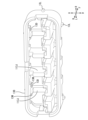
- FIG. 2 is a perspective view of the first housing as viewed from the front lower side.
- FIG. 3 is a front view of the second housing.
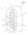
- FIG. 4 is a perspective view of the front retainer as viewed from the front lower side.
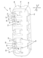
- FIG. 5 is a perspective view of the front retainer as viewed from above and rearward.
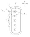
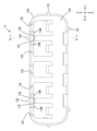
- FIG. 6 is a front view of the front retainer.
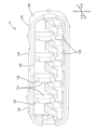
- FIG. 7 is a cross-sectional view taken along line AA in FIG.
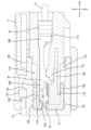
- FIG. 8 is a cross-sectional side view of the connector in a mated state.
- FIG. 9 is an enlarged front view of a main portion of the first housing to which the front retainer is attached.
- FIG. 10 is an enlarged front sectional view of the essential parts in the state where the hood portion is fitted.
- FIG. 11 is a perspective view of a front retainer according to another embodiment, as viewed from the lower rear side
- the connector of the present disclosure comprises: (1) A terminal fitting, a housing that accommodates the terminal fitting, and a front retainer that is attached to the housing and engages the terminal fitting.
- the front retainer has a front wall portion disposed on the front side of the housing, and a peripheral wall portion that extends rearward from the outer edge of the front wall portion and surrounds the outer peripheral surface of the housing.
- the outer peripheral surface of the peripheral wall portion is surrounded by a hood portion of a mating housing.
- the peripheral wall portion has an outer contact portion that contacts the inner peripheral surface of the hood portion as a part of the outer peripheral surface of the peripheral wall portion, and an inner contact portion that contacts the outer peripheral surface of the housing as a part of the inner peripheral surface.
- the front retainer has a displacement allowing portion that allows elastic displacement of the peripheral wall portion in the inward and outward directions. In the circumferential direction of the peripheral wall portion, the inner contact portion is disposed on both sides of the displacement allowing portion, and the outer contact portion is disposed between a pair of inner contact portions.
- the peripheral wall portion corresponding to the formation portions of the outer contact portion and the inner contact portion in the peripheral wall portion can be elastically displaced in the inward and outward directions via the displacement allowing portion, so that when the front retainer is attached to the housing, the inner contact portion does not come into strong contact with the housing. Furthermore, the presence of the displacement allowance portion can reduce resistance to movement, making it possible to prevent the front retainer from being stopped accidentally mid-movement.
- one displacement-allowing portion is sandwiched in the circumferential direction between a pair of inner contact portions, and the outer contact portion is disposed at a position corresponding to the circumferential center of the pair of inner contact portions.
- the outer contact portion protrudes outward from the outer peripheral surface of the peripheral wall portion, and the inner contact portion protrudes inward from the inner peripheral surface of the peripheral wall portion.
- the displacement-permitting portion is a recess formed in a portion of the front wall portion that is connected to the peripheral wall portion on the outer edge side. This configuration makes it easier for a portion of the peripheral wall portion to elastically deform inward and outward directions.
- a pair of inner contact portions sandwich a displacement-permitting portion
- the peripheral wall portion has slit portions formed in paired positions sandwiching the pair of inner contact portions.
- the connector 10 of the first embodiment includes a first housing 11 that is a housing that can be fitted to each other, a second housing 12 that is a mating housing, a front retainer 13, and female terminal fittings 30 that are terminal fittings.
- the front side is the side where the second housing 12 fits with the first housing 11.
- the front side of the second housing 12 is the side where the first housing 11 fits with.
- the first housing 11 is made of synthetic resin.
- the first housing 11 is configured as a female housing capable of accommodating the female terminal fittings 30 from the rear.
- the first housing 11 has a housing body 11A that is flat in the left-right direction (width direction) and a cylindrical surrounding wall portion 11B that surrounds the outer periphery of the housing body 11A.
- a plurality of cavities 11C are formed in the housing body 11A and aligned in the left-right direction.
- a lance 11E extending forward in a cantilever shape is provided on the inner surface of each cavity 11C (see FIG. 8).
- grooves 11F are formed between adjacent cavities 11C. Partition walls 13J of the front retainer 13, which will be described later, are inserted from the front into these grooves 11F.
- the surrounding wall portion 11B When viewed from the front (the side where the first housing 11 fits into the second housing 12), the surrounding wall portion 11B has a rectangular cylindrical shape with an upper wall, a lower wall, a left wall, and a right wall on the top, bottom, left, and right sides.
- a lock arm 11K is provided in the center of the left-right direction of the upper wall of the surrounding wall portion 11B.
- a connecting portion 11G extending inward is provided at the rear end portion of the surrounding wall portion 11B. The connecting portion 11G is connected to the outer peripheral surface of the housing main body 11A.
- a fitting space 11D is formed between the surrounding wall portion 11B and the housing main body 11A, into which the second housing 12 described below can be fitted.
- a female terminal fitting 30 is inserted into each cavity 11C from the rear.
- the female terminal fitting 30 is made of a conductive metal. As shown in FIG. 1, the female terminal fitting 30 is connected to the end of the electric wire 31, and has a square cylindrical box portion 30A at the front. A tab 32A of a male terminal fitting 32 described later is inserted and connected to the box portion 30A (see FIG. 8). The female terminal fitting 30 is prevented from falling out of the cavity 11C by a lance 11E being engaged with the rear end of the box portion 30A (see FIG. 8).
- a rubber plug 33 is fitted to the electric wire 31. The rubber plug 33 is held by the barrel portion 30B of the female terminal fitting 30 and adheres to the inner surface of the rear portion of the cavity 11C, sealing the cavity 11C liquid-tight (see FIG. 8).
- the second housing 12 is made of synthetic resin.
- the second housing 12 is configured as a male housing to which the male terminal fittings 32 can be attached.
- the second housing 12 has a terminal holding portion 12A that holds the male terminal fittings 32, and a hood portion 12B that extends forward from the outer periphery of the terminal holding portion 12A in a rectangular tubular shape.
- a plurality of tabs 32A of the male terminal fittings 32 that penetrate the terminal holding portion 12A in the front-rear direction are arranged to protrude within the hood portion 12B.
- a lock portion 12C that protrudes upward is provided at the center in the left-right direction of the upper wall of the hood portion 12B.
- the front retainer 13 is made of synthetic resin and is attached to the housing body 11A from the front (see FIG. 8). When the front retainer 13 is attached to the housing body 11A, it retains the female terminal fittings 30 and detects whether the female terminal fittings 30 are partially inserted.
- the front retainer 13 has a front wall portion 13A and a peripheral wall portion 13B that extends rearward from the outer edge of the front wall portion 13A in a cylindrical shape.
- the front wall portion 13A is disposed on the front side of the housing main body 11A and is disposed so as to cover the lower part of the front surface (the surface facing forward) of the housing main body 11A from the front (see Figure 8).
- the peripheral wall portion 13B is disposed so as to surround the outer peripheral surface of the front surface of the housing main body 11A (see Figure 8).
- the front wall portion 13A has a plurality of window holes 13C formed therethrough corresponding to each of the cavities 11C. By inserting the front end portion of the housing body 11A into these window holes 13C, the front surface of the housing body 11A and the front surface of the front wall portion 13A are aligned flush with each other (see FIG. 8).
- the front retainer 13 is provided with a plurality of detection portions 13H. These detection portions 13H are aligned in the left-right direction and extend rearward from the rear surface of the front wall portion 13A. When the front retainer 13 is properly attached to the housing main body 11A, the detection portions 13H are arranged so as to follow the underside of the front end portion of the lance 11E (see FIG. 8). In this way, the detection portions 13H restrict the lance 11E from bending downward, and prevent the female terminal fittings 30 arranged in the cavity 11C from falling out of the housing main body 11A. The detection portions 13H are provided in correspondence with each of the lances 11E.
- the front retainer 13 is provided with a plurality of partition walls 13J. The partition walls 13J are flat and arranged so as to separate adjacent window holes 13C with their thickness direction facing left-right.
- two recesses 13D are provided on the front surface of the front wall portion 13A of the front retainer 13. These recesses 13D are connected to the peripheral wall portion 13B on the outer edge side of the front wall portion 13A, and are arranged at the upper ends of the partition walls 13J located on both sides in the left-right direction. These recesses 13D vertically divide the front end of the peripheral wall portion 13B and the front end of the partition wall 13J, and vertically divide the front end of the peripheral wall portion 13B and the front wall portion 13A (see FIG. 7).
- the portion of the peripheral wall portion 13B corresponding to the arrangement position of the recesses 13D (hereinafter also referred to as the displacement portion 13K) to be elastically deformed in the vertical direction (inward and outward directions).
- the inward and outward directions are directions that intersect with the front-rear direction and correspond to the direction connecting the inside and outside of the peripheral wall portion 13B, i.e., the plate thickness direction of the peripheral wall portion 13B.
- the recess 13D is a displacement-permitting portion 13F that allows elastic displacement of the displacement portion 13K of the peripheral wall portion 13B in the inward and outward directions.
- the upper wall of the peripheral wall portion 13B of the front retainer 13 has a plurality of slit portions 13E recessed rearward from the front end. These slit portions 13E are arranged corresponding to each window hole 13C. Of the plurality of slit portions 13E, the two slit portions 13E located at the adjacent left end and the two slit portions 13E located at the adjacent right end form a pair with a recess 13D (displacement-permitting portion 13F) between them in the circumferential direction (see Figure 4).
- the peripheral wall portion 13B has a plurality of outer contact portions 13G, 13L and a plurality of inner contact portions 13M.
- the outer contact portions 13G, 13L are provided on the outer peripheral surface of the peripheral wall portion 13B and protrude outward. These outer contact portions 13G, 13L contact the inner peripheral surface of the hood portion 12B as part of the outer peripheral surface of the peripheral wall portion 13B (see Figure 10).
- Two outer contact portions 13G are provided on the upper wall of the peripheral wall portion 13B, two outer contact portions 13L are provided on the lower wall of the peripheral wall portion 13B, and one outer contact portion 13L is provided on each of the left and right walls of the peripheral wall portion 13B.
- outer contact portions 13G, 13L are formed to extend in the front-rear direction (see Figure 7).
- Each outer contact portion 13G provided on the upper wall of the peripheral wall portion 13B is located above the partition wall 13J and above the recess 13D.
- the outer contact portion 13G is disposed within the formation range of one recess 13D (displacement-permitting portion 13F).
- the four inner contact portions 13M are disposed on the inner circumferential surface of the upper wall of the peripheral wall portion 13B and protrude downward (inward) from the inner circumferential surface of the peripheral wall portion 13B. These inner contact portions 13M are formed to extend in the front-rear direction (see FIG. 7). The lower ends of the inner contact portions 13M are formed in a plane parallel to the inner circumferential surface of the peripheral wall portion 13B. Of the inner contact portions 13M, the two inner contact portions 13M on the left side are disposed so as to sandwich the partition wall 13J and the recess 13D at the left end from the left-right direction.
- the two inner contact portions 13M on the right side are disposed so as to sandwich the partition wall 13J and the recess 13D at the right end from the left-right direction.
- the inner contact portions 13M are disposed on both sides of the recess 13D (displacement-allowing portion 13F).
- the outer contact portion 13G provided on the upper wall of the peripheral wall portion 13B is disposed at a position corresponding to the circumferential center of the peripheral wall portion 13B between a pair of inner contact portions 13M that sandwich the recess 13D (displacement-allowing portion 13F) in the circumferential direction of the peripheral wall portion 13B.
- the outer contact portion 13G provided on the upper wall of the peripheral wall portion 13B is disposed between a pair of inner contact portions 13M that sandwich the recess 13D (displacement-allowing portion 13F) in the circumferential direction of the peripheral wall portion 13B.
- the slit portions 13E With respect to the circumferential direction of the peripheral wall portion 13B, the slit portions 13E, excluding the slit portion 13E in the left-right center, form a pair with a pair of inner contact portions 13M sandwiching the recess 13D (displacement-allowing portion 13F) in the circumferential direction of the peripheral wall portion 13B therebetween.
- each inner contact portion 13M contacts the upper end face (outer peripheral face) of the housing main body 11A as part of the inner peripheral face of the peripheral wall portion 13B and is pressed upward by the housing main body 11A.
- peripheral wall portion 13B (displacement portion 13K) at the portion where the inner contact portion 13M is located elastically deforms outward in the inward/outward direction (upward in the vertical direction). This prevents the inner contact portion 13M from contacting the upper end face (outer peripheral face) of the housing main body 11A too strongly.
- the detection portion 13H of the front retainer 13 is positioned so as to follow the underside of the front end portion of the lance 11E. This allows the detection portion 13H to restrict the lance 11E from bending downward, and holds the female terminal fittings 30 arranged in the cavity 11C in a non-removable state.
- partition walls 13J are inserted from the front into each groove portion 11F of the housing body 11A.
- the second housing 12 is attached from the front to the first housing 11 to which the female terminal fittings 30 and the front retainer 13 are attached. At this time, the second housing 12 is adjusted so that the hood portion 12B faces the housing body 11A and the lock portion 12C faces the lock arm 11K.
- each of the outer contact portions 13G, 13L comes into contact with the inner circumferential surface of the hood portion 12B as part of the peripheral wall portion 13B.
- the outer contact portion 13G provided on the upper wall of the peripheral wall portion 13B is pressed downward by the upper wall of the hood portion 12B as shown in FIG. 10 and is slightly crushed.
- the inner contact portion 13M is also slightly crushed.
- the peripheral wall portion 13B at the portion where the outer contact portion 13G provided on the upper wall of the peripheral wall portion 13B is arranged is elastically deformed inward in the inward-outward direction (downward in the up-down direction). Therefore, the peripheral wall portion 13B (displacement portion 13K) between the two slit portions 13E that sandwich the recess 13D is bent upward on both sides in the circumferential direction and downward in the central portion in the circumferential direction. This allows the front retainer 13 to prevent the inner contact portion 13M from contacting the outer peripheral surface of the housing main body 11A excessively strongly, while preventing the outer contact portion 13G from contacting the inner peripheral surface of the hood portion 12B excessively strongly.
- the hood portion 12B is inserted into the fitting space 11D of the first housing 11 from the front of the first housing 11.
- the locking portion 12C engages with the locking arm 11K of the first housing 11.
- the tab 32A of the male terminal fittings 32 is inserted into the box portion 30A from the front of the female terminal fittings 30.
- the hood portion 12B of the second housing 12 is fitted so as to surround the outer peripheral surface of the peripheral wall portion 13B of the front retainer 13.
- the housing body 11A and the front retainer 13 are accommodated within the hood portion 12B of the second housing 12.
- the connector 10 of the present disclosure includes a female terminal fitting 30, a first housing 11 that accommodates the female terminal fitting 30, and a front retainer 13 that is attached to a housing body 11A of the first housing 11 and engages the female terminal fitting 30.
- the front retainer 13 has a front wall portion 13A disposed on the front side of the housing body 11A of the first housing 11, and a peripheral wall portion 13B that extends rearward from the outer edge of the front wall portion 13A and surrounds the outer peripheral surface of the housing body 11A.
- the outer peripheral surface of the peripheral wall portion 13B is surrounded by a hood portion 12B of the second housing 12.
- the peripheral wall portion 13B has an outer contact portion 13G that contacts the inner peripheral surface of the hood portion 12B as a part of the outer peripheral surface of the peripheral wall portion 13B, and an inner contact portion 13M that contacts the outer peripheral surface of the housing body 11A as a part of the inner peripheral surface.
- the front retainer 13 has a displacement allowance portion 13F that allows elastic displacement in the inward and outward directions of the peripheral wall portion 13B.
- the inner contact portions 13M are disposed on both sides of one of the displacement allowance portions 13F, and the outer contact portions 13G are disposed outside between the pair of inner contact portions 13M (within the circumferential formation range of one of the displacement allowance portions 13F).
- the peripheral wall portion 13B corresponding to the portion where the outer contact portion 13G and the inner contact portion 13M are formed can be elastically displaced in the vertical direction (inward and outward directions) via the displacement allowance portion 13F, so that when the front retainer 13 is attached to the first housing 11, the inner contact portion 13M can be prevented from contacting the housing main body 11A excessively strongly. Furthermore, the presence of the displacement allowance portion 13F can reduce resistance to movement, preventing the front retainer 13 from being stopped accidentally mid-movement.
- one displacement-allowing portion 13F is sandwiched in the circumferential direction between a pair of inner contact portions 13M located at both ends of the recess 13D, and the outer contact portion 13G is disposed at a position corresponding to the circumferential center of the pair of inner contact portions 13M.
- the peripheral wall portion 13B (displacement portion 13K) corresponding to the portion of the peripheral wall portion 13B where the outer contact portion 13G and the inner contact portion 13M are formed can be deflected without bias in the circumferential direction.
- the outer contact portion 13G is shaped to protrude outward from the outer circumferential surface of the peripheral wall portion 13B
- the inner contact portion 13M is shaped to protrude inward from the inner circumferential surface of the peripheral wall portion 13B.
- the displacement-permitting portion 13F is a recess 13D formed by recessing rearward in a portion of the outer edge side of the front wall portion 13A that is connected to the peripheral wall portion 13B.
- This configuration allows the front end portion (part) of the peripheral wall portion 13B to be easily elastically deformed in the up-down direction (inward-outward direction).
- the outer contact portion 13G and the inner contact portion 13M, along with the front end portion of the peripheral wall portion 13B, are also easily elastically deformed in the up-down direction (inward-outward direction).
- a pair of inner contact portions 13M sandwich a displacement-permitting portion 13F
- the peripheral wall portion 13B has a slit portion 13E formed in a paired position sandwiching the pair of inner contact portions 13M.
- the shape of a portion of the peripheral wall portion 13B (displacement portion 13K) at the location where the outer contact portion 13G and the inner contact portion 13M are located can be made into a cantilever shape extending forward, making it easier for the front end portion (displacement portion 13K) of the peripheral wall portion 13B to elastically deform in the up-down direction (inward-outward direction).
- the rear side of the partition wall 113J where the recess 13D is located may be cut out. This configuration allows the peripheral wall portion 13B at the location where the recess 13D is located to be easily flexible.
- the outer and inner contact portions of the front retainer may be formed flush with the outer and inner peripheral surfaces of the peripheral wall portion, with a convex portion protruding inward from the inner peripheral surface of the hood portion contacting the outer contact portion, and a protrusion protruding outward from the outer peripheral surface of the housing body contacting the inner contact portion.
- the slits may be provided in the left wall, right wall, and bottom wall of the peripheral wall, and the recesses may be provided in the front wall at locations that are connected to the left wall, right wall, and bottom wall.
- the male terminal fittings may be attached to the first housing.
- multiple outer contact portions may be provided between a pair of inner contact portions.
- the outer contact portion may be formed at a position away from the circumferential center as long as it is within the range between the pair of inner contact portions.
- multiple sets of inner contact portions may be provided for one recess.
- the recess may be recessed forward into the rear surface of the front wall.
- Connector 11 First housing 11A: Housing body (housing) 11B: surrounding wall portion 11C: cavity 11D: fitting space 11E: lance 11F: groove portion 11G: connecting portion 11K: lock arm 12: second housing (mating housing) 12A: Terminal holding portion 12B: Hood portion 12C: Lock portion 13: Front retainer 13A: Front wall portion 13B: Peripheral wall portion 13C: Window hole 13D: Recess (13F: Displacement allowance portion) 13E: Slit portion 13G, 13L: Outer contact portion 13H: Detection portion 13J, 113J: Partition wall 13K: Displacement portion 13M: Inner contact portion 30: Female terminal metal fitting (terminal metal fitting) 30A: Box portion 30B: Barrel portion 31: Electric wire 32: Male terminal fitting 32A: Tab 33: Rubber stopper
Landscapes
- Connector Housings Or Holding Contact Members (AREA)
- Details Of Connecting Devices For Male And Female Coupling (AREA)
Abstract
Description
端子金具と、
前記端子金具を収容するハウジングと、
前記ハウジングに装着され、前記端子金具を係止するフロントリテーナと、
を備え、
前記フロントリテーナは、前記ハウジングの前面側に配置される前壁部と、前記前壁部の外縁から後向きに延びて前記ハウジングの外周面を包囲する周壁部を有し、
前記周壁部の外周面は、相手側ハウジングのフード部によって包囲され、
前記周壁部は、前記フード部の内周面に対し前記周壁部の外周面の一部として接触する外側接触部と、前記ハウジングの外周面に対し内周面の一部として接触する内側接触部と、を有し、
前記フロントリテーナは、前記周壁部の内外方向の弾性変位を許容する変位許容部を有し、
前記周壁部の周方向に関し、前記内側接触部は、前記変位許容部を挟んだ両側に配置され、前記外側接触部は、一対の前記内側接触部の間に配置される。
最初に本開示の実施態様を列記して説明する。
本開示のコネクタは、
(1)端子金具と、端子金具を収容するハウジングと、ハウジングに装着され、端子金具を係止するフロントリテーナと、を備えている。フロントリテーナは、ハウジングの前面側に配置される前壁部と、前壁部の外縁から後向きに延びてハウジングの外周面を包囲する周壁部を有している。周壁部の外周面は、相手側ハウジングのフード部によって包囲される。周壁部は、フード部の内周面に対し周壁部の外周面の一部として接触する外側接触部と、ハウジングの外周面に対し内周面の一部として接触する内側接触部と、を有している。フロントリテーナは、周壁部の内外方向の弾性変位を許容する変位許容部を有している。周壁部の周方向に関し、内側接触部は、変位許容部を挟んだ両側に配置され、外側接触部は、一対の内側接触部の間に配置される。この構成によれば、周壁部における外側接触部及び内側接触部の形成部位に対応する周壁部が変位許容部を介して内外方向に弾性変位できるので、フロントリテーナをハウジングに装着する際に、ハウジングに対して内側接触部が強く接触しないようにすることができる。また、変位許容部があることで移動抵抗を減らすことができ、誤ってフロントリテーナを移動途中で停止させることを防止できる。
本開示を具体化したコネクタ10を、図1から図10を参照して説明する。図中、「前側」、「後側」、「上側」、「下側」、「右側」、及び「左側」は、それぞれ「F」、「B」、「U」、「D」、「R」、及び「L」で表される。本実施形態1では、左右方向は、幅方向に相当する。図1に示すように、実施形態1のコネクタ10は、互いに嵌合可能なハウジングである第1ハウジング11、及び相手側ハウジングである第2ハウジング12と、フロントリテーナ13と、端子金具である雌端子金具30と、を備えている。前側は、第1ハウジング11に対して第2ハウジング12が嵌合する側である。また、第2ハウジング12における前側は、第1ハウジング11が嵌合する側である。
第1ハウジング11は、合成樹脂製である。第1ハウジング11は、後方から雌端子金具30を収容可能な雌ハウジングとして構成される。図2に示すように、第1ハウジング11は、左右方向(幅方向)に扁平なハウジング本体11Aと、ハウジング本体11Aの外周を包囲する筒状の包囲壁部11Bと、を有している。ハウジング本体11A内には、複数のキャビティ11Cが左右方向に並んで形成されている。各キャビティ11Cの内面には、前向きに片持ち状に延びるランス11Eが設けられている(図8参照)。
第2ハウジング12は、合成樹脂製である。第2ハウジング12は、雄端子金具32を装着可能な雄ハウジングとして構成される。図3に示すように、第2ハウジング12は、雄端子金具32を保持する端子保持部12Aと、端子保持部12Aの外周縁から前向きに角筒状をなして延びるフード部12Bと、を有している。フード部12B内には、端子保持部12Aを前後方向に貫通した雄端子金具32のタブ32Aが複数突出して配置されている。フード部12Bの上壁の左右方向中央部には、上向きに突出するロック部12Cが設けられている。
フロントリテーナ13は、合成樹脂製である。フロントリテーナ13は、ハウジング本体11Aに対して前方から取り付けられる(図8参照)。フロントリテーナ13は、ハウジング本体11Aに装着されることによって、雌端子金具30を係止し、且つ雌端子金具30の半挿入状態を検知する機能を発揮する。
図8に示すように、キャビティ11Cに後方から雌端子金具30を挿入し、雌端子金具30をキャビティ11Cの正規位置に配置すると、ランス11Eの前端が雌端子金具30の箱部30Aの後端に後方から対向する。
本開示のコネクタ10は、雌端子金具30と、雌端子金具30を収容する第1ハウジング11と、第1ハウジング11のハウジング本体11Aに装着され、雌端子金具30を係止するフロントリテーナ13と、を備えている。フロントリテーナ13は、第1ハウジング11のハウジング本体11Aの前面側に配置される前壁部13Aと、前壁部13Aの外縁から後向きに延びてハウジング本体11Aの外周面を包囲する周壁部13Bを有している。周壁部13Bの外周面は、第2ハウジング12のフード部12Bによって包囲される。周壁部13Bは、フード部12Bの内周面に対し周壁部13Bの外周面の一部として接触する外側接触部13Gと、ハウジング本体11Aの外周面に対し内周面の一部として接触する内側接触部13Mと、を有している。フロントリテーナ13は、周壁部13Bの内外方向の弾性変位を許容する変位許容部13Fを有している。周壁部13Bの周方向に関し、内側接触部13Mは、一つの変位許容部13Fを挟んだ両側に配置され、外側接触部13Gは、一対の内側接触部13Mの間(一つの変位許容部13Fの周方向の形成範囲内)の外側に配置される。
本開示は、上記記述及び図面によって説明した実施形態1に限定されるものではない。本発明には、請求の範囲と均等の意味及び請求の範囲内でのすべての変更が含まれ、下記のような実施形態も含まれることが意図される。
11…第1ハウジング
11A…ハウジング本体(ハウジング)
11B…包囲壁部
11C…キャビティ
11D…嵌合空間
11E…ランス
11F…溝部
11G…繋ぎ部
11K…ロックアーム
12…第2ハウジング(相手側ハウジング)
12A…端子保持部
12B…フード部
12C…ロック部
13…フロントリテーナ
13A…前壁部
13B…周壁部
13C…窓孔
13D…凹部(13F…変位許容部)
13E…スリット部
13G,13L…外側接触部
13H…検知部
13J,113J…仕切り壁
13K…変位部
13M…内側接触部
30…雌端子金具(端子金具)
30A…箱部
30B…バレル部
31…電線
32…雄端子金具
32A…タブ
33…ゴム栓
Claims (5)
- 端子金具と、
前記端子金具を収容するハウジングと、
前記ハウジングに装着され、前記端子金具を係止するフロントリテーナと、
を備え、
前記フロントリテーナは、前記ハウジングの前面側に配置される前壁部と、前記前壁部の外縁から後向きに延びて前記ハウジングの外周面を包囲する周壁部を有し、
前記周壁部の外周面は、相手側ハウジングのフード部によって包囲され、
前記周壁部は、前記フード部の内周面に対し前記周壁部の外周面の一部として接触する外側接触部と、前記ハウジングの外周面に対し内周面の一部として接触する内側接触部と、を有し、
前記フロントリテーナは、前記周壁部の内外方向の弾性変位を許容する変位許容部を有し、
前記周壁部の周方向に関し、前記内側接触部は、前記変位許容部を挟んだ両側に配置され、前記外側接触部は、一対の前記内側接触部の間に配置される、コネクタ。 - 一つの前記変位許容部は、一対の前記内側接触部によって前記周方向に挟まれ、
前記外側接触部は、一対の前記内側接触部の前記周方向中央部と対応する位置に配置される、請求項1に記載のコネクタ。 - 前記外側接触部は、前記周壁部の外周面に外向きに突出する形状であり、
前記内側接触部は、前記周壁部の内周面に内向きに突出する形状である、請求項1又は請求項2に記載のコネクタ。 - 前記変位許容部は、前記前壁部の外縁側における前記周壁部に連なる部位に形成された凹部である、請求項1又は請求項2に記載のコネクタ。
- 前記周方向に関し、一対の前記内側接触部が前記変位許容部を挟み、
前記周壁部は、一対の前記内側接触部を間に挟んで対をなす位置にスリット部を有している、請求項4に記載のコネクタ。
Priority Applications (2)
| Application Number | Priority Date | Filing Date | Title |
|---|---|---|---|
| US19/113,425 US20260094990A1 (en) | 2022-09-29 | 2023-08-21 | Connector |
| CN202380065055.8A CN119895669A (zh) | 2022-09-29 | 2023-08-21 | 连接器 |
Applications Claiming Priority (2)
| Application Number | Priority Date | Filing Date | Title |
|---|---|---|---|
| JP2022-156736 | 2022-09-29 | ||
| JP2022156736A JP2024050106A (ja) | 2022-09-29 | 2022-09-29 | コネクタ |
Publications (1)
| Publication Number | Publication Date |
|---|---|
| WO2024070330A1 true WO2024070330A1 (ja) | 2024-04-04 |
Family
ID=90477314
Family Applications (1)
| Application Number | Title | Priority Date | Filing Date |
|---|---|---|---|
| PCT/JP2023/030044 Ceased WO2024070330A1 (ja) | 2022-09-29 | 2023-08-21 | コネクタ |
Country Status (4)
| Country | Link |
|---|---|
| US (1) | US20260094990A1 (ja) |
| JP (1) | JP2024050106A (ja) |
| CN (1) | CN119895669A (ja) |
| WO (1) | WO2024070330A1 (ja) |
Citations (7)
| Publication number | Priority date | Publication date | Assignee | Title |
|---|---|---|---|---|
| JP2000286003A (ja) * | 1999-03-29 | 2000-10-13 | Sumitomo Wiring Syst Ltd | コネクタ |
| JP2002203630A (ja) * | 2000-12-28 | 2002-07-19 | Sumitomo Wiring Syst Ltd | コネクタ |
| US20050245124A1 (en) * | 2004-04-28 | 2005-11-03 | Sumitomo Wiring Systems, Ltd. | Connector |
| JP2010277763A (ja) * | 2009-05-27 | 2010-12-09 | Yazaki Corp | コネクタ及びコネクタ組立方法 |
| JP2014093222A (ja) * | 2012-11-05 | 2014-05-19 | Sumitomo Wiring Syst Ltd | コネクタ |
| JP2014093221A (ja) * | 2012-11-05 | 2014-05-19 | Sumitomo Wiring Syst Ltd | コネクタ |
| JP2014123446A (ja) * | 2012-12-20 | 2014-07-03 | Sumitomo Wiring Syst Ltd | コネクタ |
Family Cites Families (3)
| Publication number | Priority date | Publication date | Assignee | Title |
|---|---|---|---|---|
| JP4258146B2 (ja) * | 2001-09-26 | 2009-04-30 | 住友電装株式会社 | コネクタ |
| JP2014203633A (ja) * | 2013-04-04 | 2014-10-27 | 住友電装株式会社 | コネクタ |
| JP7414635B2 (ja) * | 2020-05-07 | 2024-01-16 | 日本航空電子工業株式会社 | コネクタ組立体 |
-
2022
- 2022-09-29 JP JP2022156736A patent/JP2024050106A/ja active Pending
-
2023
- 2023-08-21 CN CN202380065055.8A patent/CN119895669A/zh active Pending
- 2023-08-21 US US19/113,425 patent/US20260094990A1/en active Pending
- 2023-08-21 WO PCT/JP2023/030044 patent/WO2024070330A1/ja not_active Ceased
Patent Citations (7)
| Publication number | Priority date | Publication date | Assignee | Title |
|---|---|---|---|---|
| JP2000286003A (ja) * | 1999-03-29 | 2000-10-13 | Sumitomo Wiring Syst Ltd | コネクタ |
| JP2002203630A (ja) * | 2000-12-28 | 2002-07-19 | Sumitomo Wiring Syst Ltd | コネクタ |
| US20050245124A1 (en) * | 2004-04-28 | 2005-11-03 | Sumitomo Wiring Systems, Ltd. | Connector |
| JP2010277763A (ja) * | 2009-05-27 | 2010-12-09 | Yazaki Corp | コネクタ及びコネクタ組立方法 |
| JP2014093222A (ja) * | 2012-11-05 | 2014-05-19 | Sumitomo Wiring Syst Ltd | コネクタ |
| JP2014093221A (ja) * | 2012-11-05 | 2014-05-19 | Sumitomo Wiring Syst Ltd | コネクタ |
| JP2014123446A (ja) * | 2012-12-20 | 2014-07-03 | Sumitomo Wiring Syst Ltd | コネクタ |
Also Published As
| Publication number | Publication date |
|---|---|
| CN119895669A (zh) | 2025-04-25 |
| US20260094990A1 (en) | 2026-04-02 |
| JP2024050106A (ja) | 2024-04-10 |
Similar Documents
| Publication | Publication Date | Title |
|---|---|---|
| CN110416770B (zh) | 电路基板用电连接器 | |
| JP5637023B2 (ja) | ダミー栓 | |
| JP6879649B2 (ja) | シールド端子及びシールドコネクタ | |
| EP2568540A1 (en) | Electrical connector | |
| US9640905B2 (en) | Connector | |
| US10944198B2 (en) | Connector | |
| CN112821116B (zh) | 连接器 | |
| US20250132517A1 (en) | Connector | |
| US9991634B2 (en) | Connector | |
| JP5775335B2 (ja) | 突き当てコネクタ | |
| JP5556568B2 (ja) | コネクタ | |
| JP7666317B2 (ja) | コネクタ | |
| JP2024050106A (ja) | コネクタ | |
| US12347959B2 (en) | Connector | |
| CN112909608A (zh) | 端子零件 | |
| JP7460959B2 (ja) | シールドコネクタ | |
| JP7592374B2 (ja) | 固定構造 | |
| JP7626736B2 (ja) | 誤嵌合防止コネクタ | |
| JP7469175B2 (ja) | コネクタ | |
| JP2024036001A (ja) | コネクタ | |
| EP3902067B1 (en) | Electrical connecteur | |
| JP3468365B2 (ja) | 雌型コネクタ | |
| CN114284776B (zh) | 连接器 | |
| WO2022176580A1 (ja) | コネクタ | |
| JP2025067288A (ja) | 端子金具 |
Legal Events
| Date | Code | Title | Description |
|---|---|---|---|
| 121 | Ep: the epo has been informed by wipo that ep was designated in this application |
Ref document number: 23871571 Country of ref document: EP Kind code of ref document: A1 |
|
| WWE | Wipo information: entry into national phase |
Ref document number: 202380065055.8 Country of ref document: CN |
|
| WWP | Wipo information: published in national office |
Ref document number: 202380065055.8 Country of ref document: CN |
|
| NENP | Non-entry into the national phase |
Ref country code: DE |
|
| 122 | Ep: pct application non-entry in european phase |
Ref document number: 23871571 Country of ref document: EP Kind code of ref document: A1 |